

Page 1

Installation
Instructions
Experience In Motion
Dual Pressurized Seals
Dual RO, RO-TT, PTO, PT, RO-PTT,
BRO, BRT, MRO, MRT, and other
component seals
1 Equipment Check
1.1 Follow plant safety regulations prior to equipment disassembly:
1.1.1 Wear designated personal safety equipment
1.1.2 Isolate equipment and relieve any pressure in the system
1.1.3 Lock out equipment driver and valves
1.1.4 Consult plant Safety Data Sheet (SDS) files for hazardous material regulations
1.2 Disassemble equipment in accordance with the equipment manufacturer’s instructions
to allow access to seal installation area.
1.3 Remove existing sealing arrangement (mechanical seal or otherwise).
Clean seal chamber and shaft thoroughly.
1.4 Inspect surfaces under gaskets to ensure they are free from pits or scratches. Break all sharp
corners on shaft steps, threads, reliefs, shoulders, key ways, etc. over which gasket(s) must
pass and/or seal against.
1.5 Check shaft or sleeve OD, seal chamber bore, seal chamber depth, gland pilot, stud diameter,
stud bolt pattern and distance to first obstruction to ensure they are dimensionally the same
as shown in the seal assembly drawing.
1.6 Check seal assembly drawings for any modifications (reworks) to be made to the equipment
for mechanical seal installation and act accordingly.
1.7 The equipment must be earthed to prevent sparks due to static electricity discharge.
Page 2
2
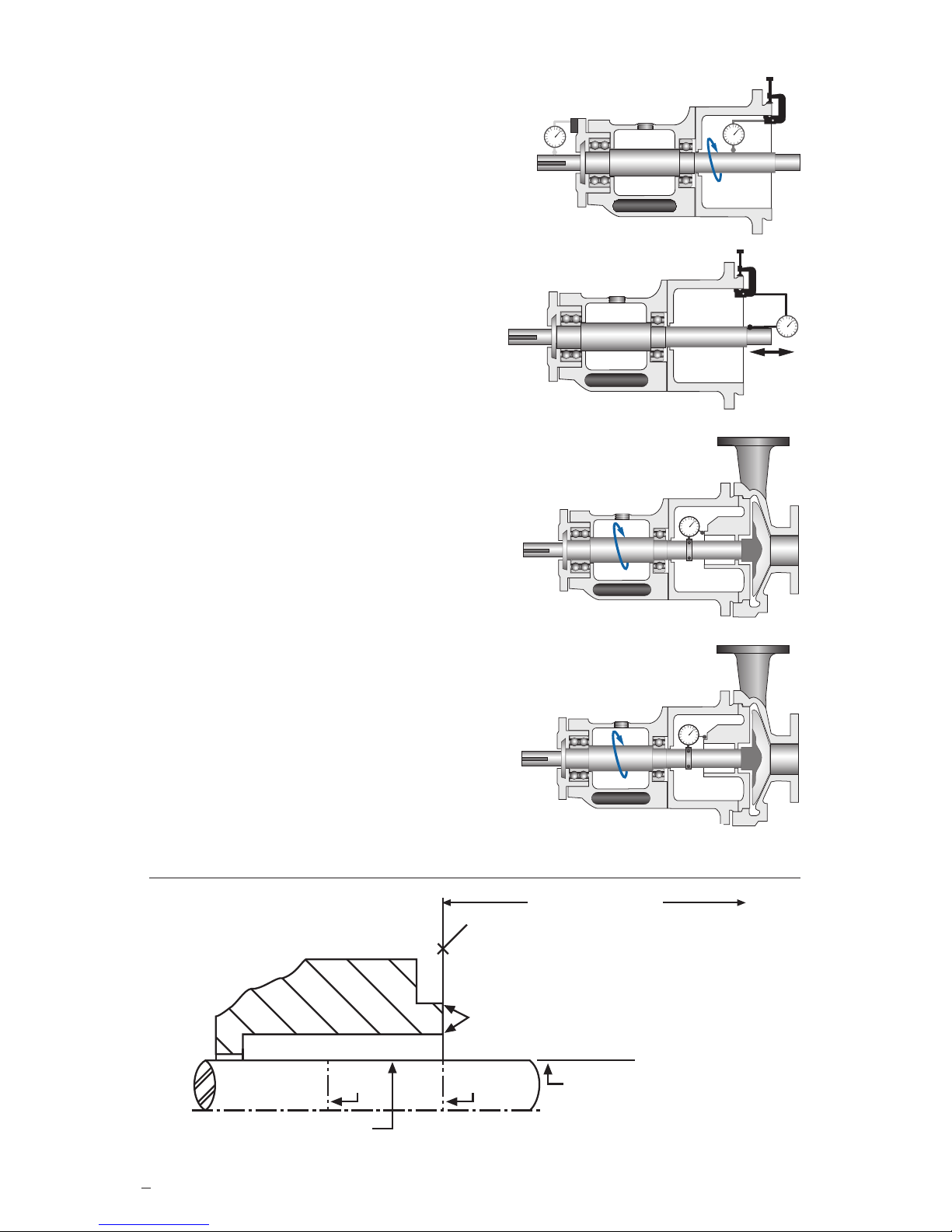
Shaft runout should be checked against the equipment manufacturer‘s specifications.
Generally, should not exceed 0.05 mm (0.002 inch) TIR (Total Indicator Reading)
at any point along the shaft for ball or roller type bearings.
For sleeve type bearings, refer to manufacturer instructions.
If the equipment is not completely dismantled, verify runout
near seal location.
The above values apply to shaft speeds in the range from
1000 to 3600 RPM. For values above and below, consult your
Flowserve representative. See Figure 1.
Shaft endplay should not exceed 0.25 mm (0.010 inch) TIR,
regardless of thrust bearing type. See Figure 2.
Radial bearing play at seal chamber face should be checked
against the equipment manufacturer’s specifications. Generally
0.05 - 0.10 mm (0.002 - 0.004 inch) will be applicable for ball o
r
roller type bearings. For sleeve or journal type bearings, values
will generally be in the order of 0.10 - 0.15 mm (0.004 - 0.006 inch).
If equipment is found outside the general range, contact the
equipment manufacturer and your Flowserve representative
to verify the equipment’s suitability for the seal.
Seal chamber squareness to the shaft centerline should
be within 0.0005 mm/mm (0.0005 inch/inch) of seal
chamber bore TIR.
Note: make sure that shaft endplay does not affect
the reading. Verify the smoothness of the seal
chamber face for a good gasket joint. See Figure 3.
Concentricity of the shaft to the seal chamber bore or gland
pilot register should be within 0.025 mm per 25 mm shaft
diameter (0.001 inch per 1 inch shaft diameter)
to a maximum of 0.125 mm (0.005 inch) TIR.
See Figure 4.
Figure 4
Figure 3
Figure 1
Figure 2
To first obstruction
Seal housing face to have a surface finish
of 1.6 μm (63 μinch) R
a
finish or better
Scribe
Mark A
Shaft or sleeve OD
+0.000 mm (+0.000 inch)
-0.050 mm (-0.002 inch)
+0.000 mm (+0.000 inch) API 610/682
-0.025 mm (-0.001 inch) DIN/ISO
Scribe
Mark B
Seal housing bore to have 3.2 μm
(125
μ
inch)
Ra finish or better
ANSI
Sleeve or shaft finish to be
0.8 μm (32 μinch) R
a
or better.
Gland pilot can be at either
of these register locations.
Surface finish requirements
Figure 5
Page 3

3
Dual Seal Installation
2 Single End Suction Vertical Split Case and Vertical In-Line Pumps
(1 seal chamber)
2.1 Scribe Mark A on the shaft or sleeve at the face of the seal housing, Figure 5. Refer to the
assembly drawing provided with the seal for the seal setting dimensions. Scribe Mark B,
Figure 5, at this dimension from Scribe Mark A. (See Section 4 for ball drive designs).
2.2 Lubricate one of the two stationary face mounting O-rings or Duraflex rings with the silicone
lubricate provided with the seal and nest this O-ring in the gland cavity. Press the outer
stationary face into the gland with the sealing surface orientated toward the inboard side of
the gland. Use hand pressure only. Position the gland over the shaft or sleeve with the
stationary face sealing surface orientated toward the seal chamber (stuffing box). Place the
gland as close to the bearing bracket as possible. Do not bump the stationary face against the
shaft as it may chip, crack, or break.
2.2 Lubricate the shaft or sleeve with the silicone lubricant provided.
2.3 Install the rotating seal assembly on the shaft or sleeve:
• Outer rotating face with rotating face gasket O-ring, V-ring, or Duraflon wedge.
• Seal assembly.
• Inner rotating face with rotating face gasket O-ring, V-ring, or Duraflon wedge.
The rotating face sealing surfaces should be facing away from the springs and toward the
stationary faces. Be sure that the seal drive pins engage the drive slots in the rotating faces.
The RO, PTO, and similar designs have buttoned seal assemblies that can most easily be
installed on the shaft or sleeve as a unit with the rotating face gasket O-rings in place in the
bore of the rotating faces. The BRO, MRO, and similar designs are generally larger in diameter
and the rotating seal parts are most easily installed as individual components.
Handle Duraflon V-rings, wedge rings, Durafite, and Duraflex with extreme care. Duraflon
V-rings must be assembled individually and not pushed on the shaft or sleeve while they are
part of the rotating face or rotating seal assembly. Avoid nicking or pinching either lip of the
V-ring. Use both V-rings, they work together to form an effective seal.
Position the rotating seal assembly in its final axial position with the indicated position of the
seal drive lined up with Scribe Mark B. Tighten the seal drive set screws firmly and evenly.
2.4 Lubricate the seal chamber bore with the lubricant provided. The seal chamber is usually the
stuffing box contained in the pump back plate.
2.5 Lubricate the other stationary face gasket O-ring and place it on the back shoulder of the
inner stationary face. Slide the inner stationary face with the O-ring into position at the bottom
of the chamber. The rubbing or sealing surface of the inner stationary face should face out,
away from the impeller.
2.6 Wipe the seal faces clean with alcohol. Seal faces should not be lubricated but should be left
clean and dry.
2.7 Install the seal chamber (pump back-plate) and assemble the pump. Position the gland
to the face of the seal housing. Be sure the gland pilot is properly engaged. Tighten the gland
stud nuts evenly, cross stagger the adjustment of the nuts. Follow the equipment manufacturer's
recommendations for gland stud nut torque. In the absence of recommendations, gland nuts
should only be torqued to establish a leak tight seal at the gasket. Proper gland bolt adjustment
is especially important with a clamp style stationary face where excessive torque may damage
the face.
2.8 See Section 5, Operational Recommendations, before starting pump.
Page 4

3 Double Suction and Multistage Horizontal Split Case Pumps
(2 seal chambers)
Note: The parting gasket between the upper and lower sections of the pump casing must be flush
with the seal chamber bore and face or leakage will occur past the O-rings and gaskets.
3.1 Scribe Mark A on the shaft or sleeve at the face of the seal housing, Figure 5. Refer to the
assembly drawing provided with the seal for the seal collar dimension setting shown in a box .
Scribe Mark B, Figure 5, at this dimension from Scribe Mark A. (See Section 4 for ball drive
designs).
3.2 Lubricate the seal chamber bore with the lubricant provided. The seal chambers are usually
the stuffing boxes, located near the bearing brackets.
3.3 Lubricate one of the stationary face mountings and place it on the back shoulder of the inner
stationary face. Slide the inner stationary face with the O-ring into position at the bottom of the
chamber. The rubbing or sealing surface of the inner stationary face should face out, away from
the pump impeller.
3.4 Wipe the seal faces clean with alcohol. Seal faces should not be lubricated but should be left
clean and dry.
3.5 Lubricate the shaft or sleeve and rotating gasket O-ring with the silicone lubricant provided.
3.6 Install the rotating seal assembly on the shaft or sleeve:
• Inner rotating face with rotating face gasket O-ring, V-ring, or Duraflon wedge.
• Seal assembly.
• Outer rotating face with rotating face gasket O-ring, V-ring, or Duraflon wedge.
The rotating face sealing or rubbing surfaces should be facing away from the springs and
toward the stationary face. Be sure that the seal drive ring drive pins engage the drive slots in
the seal rings.
The RO, PTO, and similar designs have unitized seal assemblies, they can most easily be
installed on the shaft or sleeve as a unit with the rotating face gasket O-rings in place in the
bore of the rotating face. The BRO, MRO, and similar designs are generally larger in diameter
and the rotating seal parts are most easily installed as individual components.
Handle Duraflon V-rings, wedge rings, Durafite, and Duraflex with extreme care. Duraflon
V-rings must be assembled individually and not pushed on the shaft or sleeve while they are
part of the rotating face or rotating seal assembly. Avoid nicking or pinching either lip of the
V-ring. Use both V-rings, they work together to form an effective seal.
Position the rotating seal assembly in its final axial position with the indicated position of the
seal drive lined up with Scribe Mark B. Tighten the seal drive set screws firmly and evenly.
3.7 Lubricate the other stationary face gasket O-ring or Duraflex ring with the silicone lubricate
provided and nest this O-ring in the gland cavity. Press the outer stationary face into the
gland with the sealing surface orientated toward the inboard side of the gland. Use hand
pressure only.
3.8 Position the gland over the shaft or sleeve with the stationary face sealing surface orientated
toward the seal chamber (stuffing box) and the gland or stationary pilot properly engaged.
Do not bump the stationary face against the shaft as it may chip, crack, or break. Tighten the
gland stud nuts evenly, cross stagger the adjustment of the nuts. Follow the equipment
manufacturer's recommendations for gland stud nut torque. In the absence of recommendations,
gland nuts should only be torqued to establish a leak tight seal at the gasket. Proper gland bolt
adjustment is especially important with clamp style stationary faces where excessive torque
may damage the face.
4
Page 5
5
3.9 Reassemble the pump.
3.10 See Section 5, Operational Recommendations, before starting pump.
4 Ball Drive Seal Designs
The drive ball replaces the set screws in the seal drive and provides the following features:
• It compensates for axial shaft adjustment to reset the impeller
• It compensates for axial shaft movement due to thermal expansion or mechanical
loading of the equipment.
• It provides for positive seal drive without the use of seal setting dimensions.
4.1 Follow the instructions in Section 2 or 3, Scribe Mark A or B are unnecessary.
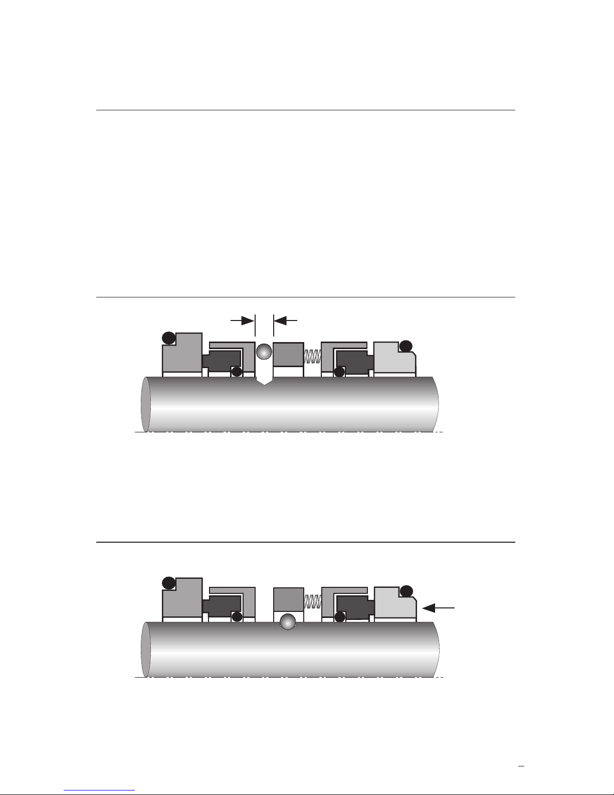
4.2 Slide the rotating seal assembly down the shaft or sleeve until the predrilled indentation in the
shaft or sleeve is directly under the spring gap. Insert the ball into the predrilled indentation.
See Figure 6.
Figure 6
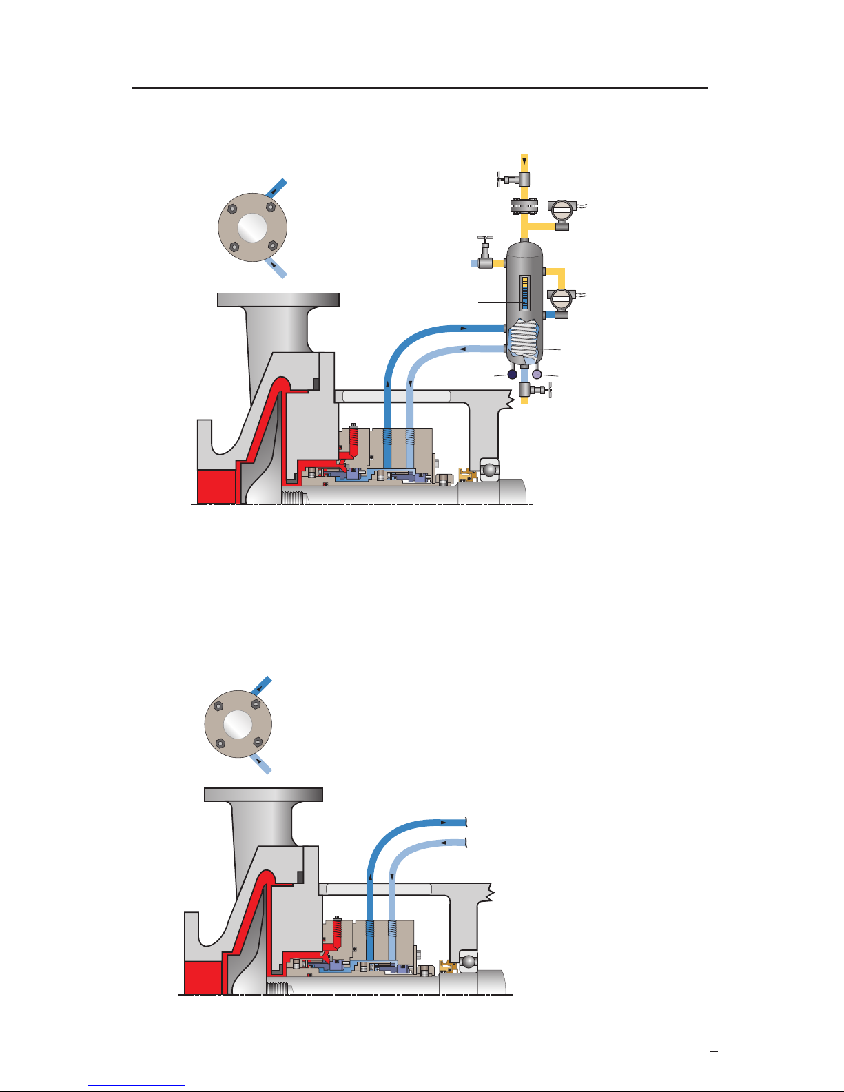
Figure 7
4.3 Slide the rotating seal assembly forward to confine the ball in the seal drive slot. See
Figure 7.
4.4 Complete the seal and pump assembly as instructed in Sections 2 and 3.
Page 6

6
5 Operational Recommendations
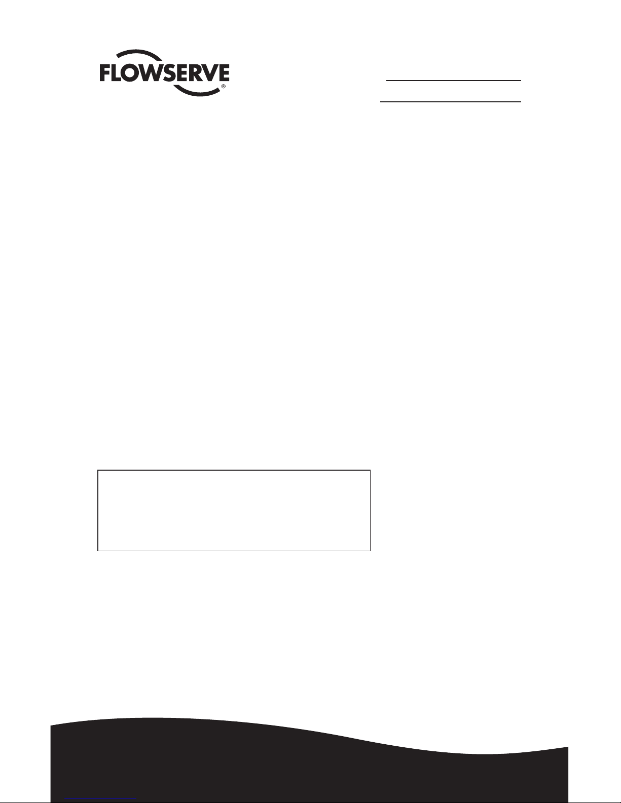
See Figure 8 for a suggested sealing fluid supply system for Dual Pressurized Seal designs.
For other systems using Supply Tanks or Circulators refer to the tank or circulator instructions
or contact Flowserve.
5.1 The Dual Pressurized Seal requires a constant supply of a clean barrier fluid. Whenever the
equipment is in operation circulate clean barrier fluid from a reliable external source between
the seals in the seal chamber. Always start up the barrier fluid supply system before starting
the equipment. Maintain the fluid pressure between the seals at least 103 kPa (15 psig) greater
than the maximum pressure of the pumped product acting on the inner seal. Figure 8 shows
Plan 53 with a pressurized supply tank and Plan 54 with an external support system.
Do not exceed the pressure-velocity (P-V) limits of the seal, see the pressure-velocity curves
for this seal.
5.2 Do not start up the equipment dry. Vent air from the casing of the pump and the seal chamber
before startup.
5.3 If the seal runs hot or squeals, check the seal housing dimensions to ensure that the seal is not
over-compressed and inspect the barrier fluid supply system. Do not allow the equipment to
run for any extended time if the seal gets hot or squeals.
For special problems encountered during installation, contact your nearest Flowserve Representative
or Authorized Distributor.
The images of parts shown in these instructions may differ visually from the actual
parts due to manufacturing processes that do not affect the part function or quality.
6 Repair
This product is a precision sealing device. The design and dimension tolerances are critical to seal
performance. Only parts supplied by Flowserve should be used to repair a seal. To order replacement
parts, refer to the part code and B/M number. A spare backup seal should be stocked to reduce repair
time.
When seals are returned to Flowserve for repair, decontaminate the seal assembly and include an
order marked "Repair or Replace." A signed certificate of decontamination must be attached.
A Safety Data Sheet (SDS) must be enclosed for any product that came in contact with the seal.
The seal assembly will be inspected and, if repairable, it will be rebuilt, tested, and returned.
Page 7
7
Recommended Barrier Supply System for Dual Pressurized Seals
Figure 8
Plan 53A
outlet
inlet
pressure source,
normally open
pressure
transmitter
level
transmitter
cooling coils
cooling in
drain,
normally
closed
cooling out
reservoir
liquid fill,
normally closed
level indicator
seal
end view
orifice
outlet
inlet
from / to external
pressurized barrier circulating system
seal
end view
Plan 54
Page 8
FIS106eng REV 09/2018 Printed in USA
flowserve.com
To find your local Flowserve representative
and find out more about Flowserve Corporation,
visit www.flowserve.com
Flowserve Corporation has established industry leadership in the design and manufacture of its products.
When properly selected, this Flowserve product is designed to perform its intended function safely during its
useful life. However, the purchaser or user of Flowserve products should be aware that Flowserve products
might be used in numerous applications under a wide variety of industrial service conditions. Although
Flowserve can provide general guidelines, it cannot provide specific data and warnings for all possible
applications. The purchaser/user must therefore assume the ultimate responsibility for the proper sizing
and selection, installation, operation, and maintenance of Flowserve products. The purchaser/user should
read and understand the Installation Instructions included with the product, and train its employees and
contractors in the safe use of Flowserve products in connection with the specific application.
While the information and specifications contained in this literature are believed to be accurate, they are
supplied for informative purposes only and should not be considered certified or as a guarantee of satisfactory
results by reliance thereon. Nothing contained herein is to be construed as a warranty or guarantee, express
or implied, regarding any matter with respect to this product. Because Flowserve is continually improving and
upgrading its product design, the specifications, dimensions and information contained herein are subject to
change without notice. Should any question arise concerning these provisions, the purchaser/user should
contact Flowserve Corporation at any one of its worldwide operations or offices.
© 2017 Flowserve Corporation
USA and Canada
Kalamazoo, Michigan USA
Telephone: 1 269 381 2650
Telefax: 1 269 382 8726
Europe, Middle East, Africa
Etten-Leur, the Netherlands
Telephone: 31 765 028 200
Telefax: 31 765 028 487
Asia Pacific
Singapore
Telephone: 65 6544 6800
Telefax: 65 6214 0541
Latin America
Mexico City
Telephone: 52 55 5567 7170
Telefax: 52 55 5567 4224
TO REORDER REFER TO
B/M #
F.O
.
 Loading...