

Page 1
Installation
Experience In Motion
Instructions
BW Seals
General Service
Balanced Pusher Seal
Q, QB, QBQ, QBS, QBU, QBQ LZ
®
Q, QB Series
Page 2
1 Equipment Check
1.1 Follow plant safety regulations:
• lock out motor and valves.
• wear designated personal safety equipment.
• relieve any pressure in system.
• consult plant MSDS les for hazardous material regulations.
1.2 Adjust the bearings, coupling, and impeller so that the shaft is in its operating
axial position. This shaft position must be used to check all seal setting (SS)
dimensions during installation. Disassemble equipment to allow access to seal
installation area.
1.3 Remove all burrs, nicks or scratches, and sharp edges from the shaft and sleeve
including sharp edges of keyways and threads. Replace worn shaft or sleeve. Make
sure the seal housing bore, face, and sealing uid ush taps are clean and free of
burrs and sharp edges that might damage gasket.
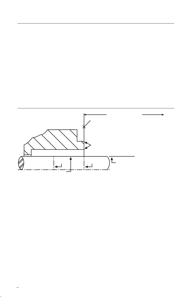
Seal Chamber Requirements Figure 1
To first obstruction
Face of seal housing to be square to the
axis of the shaft to within 0.0005 mm/mm
(0.0005 inch/inch) of seal chamber bore TIR
and have a 1.6 μm (63 μinch) R finish or better
Gland pilot can be at either of these
register locations, concentric to within
0.125 mm (0.005 inch) of shaft or
Seal housing bore to have 3.2 μm
(125
μ
inch) R finish or better
a
Scribe
Mark B
Sleeve or shaft finish to be
0.8 μm (32 μinch) R or better
• Bearings must be in good condition
• Maximum lateral or axial movement of shaft (end play) = 0.25 mm (0.010 inch) TIR
• Maximum shaft runout at face of seal housing = 0.05 mm (0.002 inch) TIR
• Maximum dynamic shaft deflection at seal housing = 0.05 mm (0.002 inch) TIR
a
sleeve OD TIR
Scribe
Mark A
Shaft or sleeve OD
+0.000 mm (+0.000 inch)
-0.050 mm (-0.002 inch)
+0.000 mm (+0.000 inch) API 610/682
-0.025 mm (-0.001 inch) DIN/ISO
a
ANSI
1.4 Check requirements for shaft, sleeve, and seal housing. See Figure 1.
1.5 Check assembly drawing included with the seal for equipment dimensions,
seal design, materials of construction, and piping connections.
1.6 Check shaft or sleeve OD, box depth, box bore, and distance to the rst
obstruction to ensure that they are dimensionally the same as shown on the
seal assembly drawing.
1.7 Check gland pilot and bolt holes to ensure they are adaptable to the equipment
and are the same as shown on the assembly drawing.
1.8 Handle all seal parts with care, they are manufactured to precise tolerances.
The seal faces are of special importance. These two sealing faces are lapped at
to within two light bands (23.2 millionths of an inch).
Keep the seal faces perfectly clean at all times.
The images of parts shown in these instructions may differ visually from the actual
2
parts due to manufacturing processes that do not affect the part function or quality.
Page 3
2 Assembly of Seal Components
2.1 Prepare rotating assembly for installation. The rotating assembly is comprised of
the spring holder, springs, retaining ring, set screws, rotating face and rotating face
gasket. Examine all parts - clean with alcohol or acetone as needed.
Caution: Consult material safety data sheets for proper handling of alcohol or acetone.
2.1.1 Install the set screws into the spring holder.
Caution: Set screws must not protrude into spring holder’s bore.
2.1.2 Install the springs in the spring pockets of the spring holder.
2.1.3 Align the retaining ring with the drive keys, compress the springs and rotate
the retaining ring so that the notches are no longer aligned with drive keys
to retain springs. Check springs to make sure none are bent over.
2.1.4 Install the rotating face gasket in the recess of the rear of the rotating face.
Lubricate the inside diameter of the rotating face gasket with silicone base
grease only, unless otherwise specied on seal drawing.
2.1.5 Press down rotating face gasket making sure it is retained in the groove
provided.
2.1.6 Install the rotating face in the spring holder with the slots in the face
aligning with the keys.
2.2 The rotating assembly can now be installed on the shaft or sleeve. Use caution
not to dislodge rotating face gasket. See Figure 2.
Installed Seal Assembly on Shaft or Customer’s Sleeve Figure 2
SS
SS
3 Seal Setting for Seal on Shaft or Customer’s Sleeve
For proper seal installation, you must obtain the correct seal assembly drawing for your
application.
3.1 Inspect pump shaft. Clean and remove any burrs, nicks, scratches, etc. which could
cause damage to gaskets when assembling seal.
3.2 Secure the seal assembly in place at its correct seal setting position (SS) by
tightening the rotating assembly set screws. See Figure 2. Refer to the seal
assembly drawing for correct seal setting dimension.
3
Page 4

3.3 O-ring Mounted Stationary Face
3.3.1 Assemble seat gasket to stationary face (lubricate gasket with silicone base
grease only, unless otherwise specied on seal drawing) and install in gland.
Caution: If anti-rotation pin is used, make sure stationary face is properly seated.
Do not get grease on running face.
3.3.2 Install gland gasket - Use silicone grease if necessary to retain gasket.
3.4 Clamped Stationary Face
3.4.1 Install at gasket into gland.
3.4.2 Install stationary face into gland.
3.4.3 Install second at gasket to stationary face.
Note: If two gasket materials are supplied, install PTFE gasket at this location.
Use silicone grease to retain gasket if necessary.
Do not get grease on running face.
3.5 Using lint free tissue, clean stationary and rotating face mating surfaces.
Alcohol or acetone can be used as a cleaning agent to assure clean, lm free,
dry faces. Any other materials may cause premature seal failure.
Caution: Consult material safety data sheets for proper handling of alcohol or acetone.
3.6 Assemble gland to seal chamber face. See Figure 2.
Caution: During gland assembly over shaft, be sure stationary face is not damaged.
Secure bolts attaching gland to housing.
Note: Even torque is required on all gland bolts to assure proper seal operation.
Tighten gland stud nuts evenly, cross stagger the adjustment of the nuts. Follow the
equipment manufacturer’s recommendation for gland stud nut torque. In the absence
of recommendations, gland stud nuts should only be torqued to establish a leak tight
seal at the gasket. Proper land bolt adjustment is especially important with clamp
style inserts where torque may damage the insert. In this case, gland stud nuts
should be torqued to a maximum of 13.5 N-m (10 ft-lbs).
4 Hook Sleeve Mount
For proper seal installation, you must obtain the correct seal assembly drawing
for your application.
4.1 Inspect pump shaft. Clean and remove any burrs, nicks, scratches, etc.
which could cause damage to gaskets when assembling seal.
4.2 Assemble shaft sleeve and at gasket to pump shaft and seat in accordance
with pump manufacturer’s specications. Inspect for and remove any burrs.
Seal Setting on Hook Sleeve Figure 3
SS
4
Page 5

4.3 Verify seal setting (SS) reference dimension on the seal drawing. This is the
dimension from the seal chamber face to a machined step or locator on the shaft.
See Figure 3.
4.4 If shaft sleeve has no locating shoulder, blue sleeve and scribe line for location of
spring holder as shown on seal assembly drawing.
4.5 Slide rotating assembly onto shaft sleeve, locating in accordance with the seal
assembly drawing. Use caution not to dislodge rotating face gasket.
4.6 Tighten seal assembly set screws to shaft sleeve ensuring seal assembly is
retained at proper seal setting location as noted on seal assembly drawing.
4.7 O-ring mounted Stationary Face
4.7.1 Assemble seat gasket to stationary face (lubricate gasket with silicone base
grease only) and install in gland.
Caution: If anti-rotation pin is used make sure stationary face is properly seated.
Do not get grease on running face.
4.7.2 Install gland gasket, use silicon grease if necessary to retain gasket.
4.8 Clamped Stationary Face
4.8.1 Install at gasket into inner gland.
4.8.2 Install stationary face into gland.
4.8.3 Install second at gasket to stationary face.
Note: If two gasket materials are supplied, install PTFE gasket at this location.
Use silicone grease to retain gasket if necessary.
Do not get grease on running face.
4.9 Using lint free tissue, clean stationary and rotating face mating surfaces. Alcohol
or acetone can be used as a cleaning agent to assure clean, lm free, dry faces. Any
other materials may cause premature seal failure.
Caution: Consult material safety data sheet for proper handling of alcohol or acetone.
4.10 Assemble gland to seal chamber face. See Figure 4.
Caution: During gland assembly over shaft and sleeve, be sure stationary face is not
damaged. Secure bolts attaching gland to housing.
Note: Even torque is required on all gland bolts to assure proper seal operation.
Tighten gland stud nuts evenly, cross stagger the adjustment of the nuts. Follow the
equipment manufacturer’s recommendation for gland stud nut torque. In the absence
of recommendations, gland stud nuts should only be torqued to establish a leak tight
seal at the gasket. Proper land bolt adjustment is especially important with clamp
style inserts where torque may damage the insert. In this case, gland stud nuts
should be torqued to a maximum of 13.5 N-m (10 ft-lbs).
Installed Seal Assembly on Hook Sleeve Figure 4
5
Page 6

5 Cartridge Mount
5.1 For proper seal installation you must have current seal assembly drawing
for your application.
5.2 Inspect pump shaft. Clean and remove any burrs, nicks, scratches, etc.,
which could cause damage to gaskets when installing cartridge seal.
5.3 Carefully install the seal onto the shaft and locate against the face of the seal
chamber. Take care not to impact the seal cartridge as damage to internal
components can occur.
5.4 Orient ports on the seal cartridge as shown on the seal assembly drawing.
5.5 Evenly torque gland bolts/nuts to prevent uneven gland pressure against the
seal chamber.
5.6 Adjust bearings, coupling, and impeller so that the shaft is in its nal operating position.
5.7 Determine the type of setting device used by the seal design and follow the
appropriate instructions.
Type 1 - none
Type 2 - setting plates
Type 3 - setting blocks
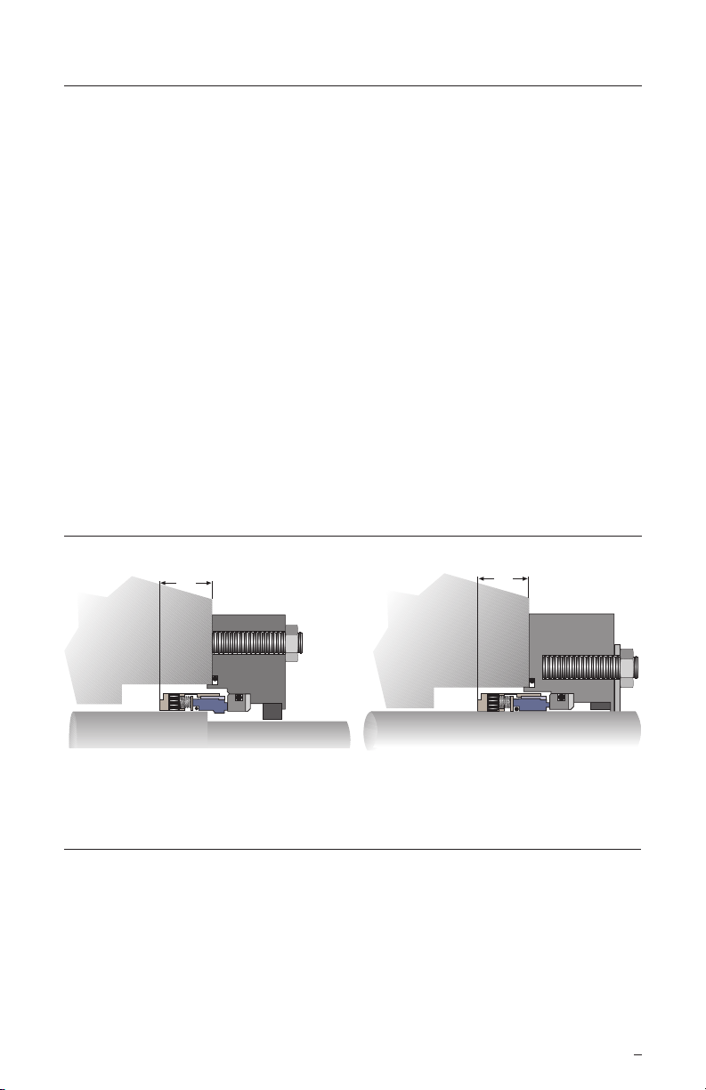
Type 1 (none) Figure 5
SS Gap
(from assembly drawing)
• Determine proper seal setting (SS) gap specied on seal assembly drawing.
• Adjust sleeve drive collar position relative to gland to establish proper gap.
• Tighten drive collar set screws.
Type 2 (setting plates) Figure 6
Setting Plate Bolt
Setting Plate
Set Screws
• Tighten drive collar set screws to shaft.
• Loosen setting plate attachment bolts and rotate or slide setting plates clear
of drive collar.
• Retighten setting plate attachment bolts.
6
Page 7

Type 3 (setting blocks) Figure 7
Setting Block
• Tighten drive collar set screws to shaft.
• Loosen and remove setting blocks.
6 Piping Instructions
Do not start up the equipment dry. Vent air from the casing of the pump and the seal
chamber before startup.
Refer to assembly drawing for mechanical seal piping instructions.
Note: For special problems encountered during installation, contact your nearest
Flowserve Sales and Service Representative or Authorized Distributor.
7 Repair
This product is a precision sealing device. The design and dimension tolerances are critical
to seal performance. Only parts supplied by Flowserve should be used to repair a seal. To
order replacement parts, refer to the part code and B/M number. A spare backup seal should
be stocked to reduce repair time.
When seals are returned to Flowserve for repair, decontaminate the seal assembly and
include an order marked "Repair or Replace." A signed certicate of decontamination
must be attached. A Material Safety Data Sheet (MSDS) must be enclosed for any
product that came in contact with the seal. The seal assembly will be inspected and,
if repairable, it will be rebuilt, tested, and returned.
7
Page 8

TO REORDER REFER TO
flowserve.com
B/M #
F. O .
FIS135eng REV 07/13 Printed in USA
To find your local Flowserve representative
and find out more about Flowserve Corporation,
visit www.flowserve.com
Flowserve Corporation has established industry leadership in the design and manufacture of its products. When
properly selected, this Flowserve product is designed to perform its intended function safely during its useful life.
However, the purchaser or user of Flowserve products should be aware that Flowserve products might be used
in numerous applications under a wide variety of industrial service conditions. Although Flowserve can provide
general guidelines, it cannot provide specific data and warnings for all possible applications. The purchaser/user
must therefore assume the ultimate responsibility for the proper sizing and selection, installation, operation, and
maintenance of Flowserve products. The purchaser/user should read and understand the Installation Instructions
included with the product, and train its employees and contractors in the safe use of Flowserve products in connection
with the specific application.
While the information and specifications contained in this literature are believed to be accurate, they are supplied for
informative purposes only and should not be considered certified or as a guarantee of satisfactory results by reliance
thereon. Nothing contained herein is to be construed as a warranty or guarantee, express or implied, regarding any
matter with respect to this product. Because Flowserve is continually improving and upgrading its product design,
the specifications, dimensions and information contained herein are subject to change without notice. Should any
question arise concerning these provisions, the purchaser/user should contact Flowserve Corporation at any one of
its worldwide operations or offices.
© 2013 Flowserve Corporation
USA and Canada
Kalamazoo, Michigan USA
Telephone: 1 269 381 2650
Telefax: 1 269 382 8726
Europe, Middle East, Africa
Roosendaal, the Netherlands
Telephone: 31 165 581400
Telefax: 31 165 554590
Asia Pacific
Singapore
Telephone: 65 6544 6800
Telefax: 65 6214 0541
Latin America
Mexico City
Telephone: 52 55 5567 7170
Telefax: 52 55 5567 4224
 Loading...