

Page 1

USER INSTRUCTIONS
®
Worthington
centrifugal pumps
Vertical QLQ and QLQC
Installation
Operation
multiple stage, double suction, vertical wet pit and canned
centrifugal pumps
PCN=87900027 – 06/14 (E ) Original instructions
Maintenance
These instructions must be read prior to installing,
operating, using and maintaining this equipment.
Page 2

QLQ, QLQC USER INSTRUCTIONS ENGLISH 87900027 – 06/14
CONTENTS:
PAGE
1 INTRODUCTION AND SAFETY ........................... 4
1.1 General ........................................... ................ 4
1.2 CE marking and approvals .............................. 4
1.3 Disclaimer ....................................................... 4
1.4 Copyright ........................................................ . 4
1.5 Duty conditions............................ .................... 4
1.6 Safety .............................................................. 5
1.7 Nameplate and safety labels ........................... 8
1.8 Specific machine performance .................... .... 8
1.9 Noise level ........................ ............................... 9
2 TRANSPORT AND STORAGE ........................... 10
2.1 Consignment receipt and unpacking ............ 10
2.2 Handling ........................................................ 10
2.3 Lifting ............................................................. 10
2.4 Storage ................................................ .......... 12
2.5 Recycling and end of product life .................. 14
3 PUMP DESCRIPTION ......................................... 15
3.1 Configurations ............................................... 15
3.2 Nomenclature ................................................ 15
3.3 Design of major parts .................................... 16
3.4 Performance and operating limits ................. 18
6 MAINTENANCE ................................................... 42
6.1 Maintenance schedule ...................................42
6.2 Spare parts ....................................................44
6.4 Tools required ................................................44
6.5 Fastener torque .............................................44
6.6 Setting impeller clearance .............................45
6.7 Disassembly ..................................................45
6.8 Examination of parts .......................... ... .... .... .46
6.9 Reassemble procedure .................................50
7 FAULTS; CAUSES AND REMEDIES ................... 52
8 PARTS LIST AND DRAWINGS ............................ 54
PAGE
4 INSTALLATION .................................................... 19
4.1 Location ......... ................................................ 19
4.2 Part assemblies............................................. 23
4.3 Foundation .................................................... 23
4.4 Grouting ........................................................ 25
4.5 Initial alignment ............................................. 26
4.6 Piping ............................................................ 28
4.7 Electrical connections ................................. .. 30
4.8 Protection systems ........................................ 30
5 COMMISSIONING, STARTUP, OPERATION AND
SHUTDOWN ................................... ......................... 32
5.1 Pre-commissioning procedure ...................... 32
5.2 Pump Lubricants ........................................... 32
5.3 Lubrication of thrust bearing ......................... 33
5.4 Impeller adjustment ....................................... 34
5.5 Direction of rotation ....................................... 36
5.6 Guarding ....................................................... 36
5.7 Priming and auxiliary supplies ............ .... .... .. 36
5.8 Starting the pump .......................................... 36
5.9 Running or operation .................................... 39
5.10 Stopping and shutdown .............................. 40
5.11 Hydraulic, mechanical and electrical duty ... 40
Page 2 of 61
Page 3

QLQ, QLQC USER INSTRUCTIONS ENGLISH 87900027 – 06/14
INDEX:
PAGE
Alignment (4.5) .................................................. ...... 25
Assembly (6.9) ......................................................... 49
ATEX marking (1.6.4.2) ............................................. 7
CE marking and approvals (1.2) ................................ 4
Clearances (6.6) ................................................ ...... 44
Commissioning and operation (5) ............................ 31
Compliance, ATEX (1.6.4.1) ...................................... 6
Configurations (3.1) ........................................... ...... 15
Copyright (1.4) ........................................................... 4
Design of major parts (3.3) ...................................... 16
Direction of rotation (5.5) ......................................... 35
Disassembly (6.7) ............................... ..................... 44
Disclaimer (1.3) .......................................................... 4
Dismantling (see 6.7, Disassembly) ........................ 44
Drawings (8) .................... .... .... ... .... .... .... ....... .... .... .. 55
Duty conditions (1.5) .................................................. 4
Electrical connections (4.7) ....................... .............. 29
End of product life (2.5) ........................................... 14
Examination of parts (6.8) ....................................... 45
Fastener torques (6.5) ............................................. 43
Faults; causes and remedies (7) ............................. 51
General assembly drawings (8.1) ............................ 53
Grouting (4.4) ............................................. .............. 25
Guarding (5.6) .................................................... ...... 35
Handling (2.2) .......................................................... 10
Hydraulic, mechanical and electrical duty (5.10) ..... 39
Impeller clearance (6.6) ........................................... 44
Inspection (see 6.1, Maintenance schedule) ........... 41
Installation (4) .......................................................... 19
Lifting (2.3) ............................................................... 10
Location (4.1) ........................................................... 19
Lubrication, thrust bearings (5.3) ............................. 33
Lubrication, pump (see 5.2, Pump lubricants) ......... 31
Maintenance (6) ....................................................... 41
Maintenance schedule (6.1) .................................... 41
Name nomenclature (3.2) ........................................ 15
Nameplate (1.7.1) ................................... ... .... .... .... ... . 8
Operating limits (3.4) ....... .... .... ... .... .... ....... .... .... .... .. 18
Ordering spare parts (6.2.1) .................................... 43
Part assemblies (4.2) ............................................... 23
Parts lists (8) ............................................................ 53
Performance (3.4) .................................................... 18
Piping (4.6) .............. ................................................ 27
Pre-commissioning (5.1) .......................................... 31
Protection systems (4.8) .......................................... 30
Priming and auxiliary supplies (5.7) ......................... 35
Reassembly (see 6.9, Assembly) ............................ 49
Receipt and unpacking (2.1) .................................... 10
Recommended oil lubricants (5.2.2) ........................ 31
Recommended spares (6.3) .................................... 43
Recycling (2.5) ......................................................... 14
Replacement parts (see 6.2 and 6.3) ...................... 43
Running and operation (5.9) .................................... 38
PAGE
Safety action (1.6.3) ................................................... 5
Safety labels (1.7.2) ... ................................................ 8
Safety markings (1.6.1) .............................................. 5
Safety, protection systems ....................................... 30
Sectional drawings (8) .............................................. 53
Sound level (see 1.9, Noise level) .............................. 8
Spare parts (6.2) ................... .... ....... .... .... .... ... .... .... . 43
Specific machine performance (1.8) .......................... 8
Starting the pump (5.8) ............................................ 35
Stop/start frequency (5.8.8) ...................................... 38
Stopping and shutdown (5.10) ................................. 39
Storage, pump (2.4) ................................................. 12
Storage, spare parts (6.2.2) ..................................... 43
Supplementary manuals or info, contacts ................ 60
Tools required (6.4) .................................................. 43
Torques for fasteners (6.5) ....................................... 43
Trouble-shooting (see 7) .......................................... 51
Vibration (5.8.7) ........................................................ 38
Page 3 of 61
Page 4

QLQ, QLQC USER INSTRUCTIONS ENGLISH 87900027 – 06/14
1 INTRODUCTION AND SAFETY
1.1 General
These instructions must always be kept
close to the product's operating location or
directly with the product.
Flowserve products are designed, developed and
manufactured with state-of-the-art technologies in
modern facilities. The unit is produced with great care
and commitment to continuous quality control,
utilizing sophisticated quality techniques and safety
requirements.
Flowserve is committed to continuous quality
improvement and being at service for any further
information about the product in its installation and
operation or about its support products, repair and
diagnostic services.
These instructions are intended to facilitate
familiarization with the product and its permitted use.
Operating the product in compliance with these
instructions is important to help ensure reliability in
service and avoid risks. The instructions may not take
into account local regulations; ensure such
regulations are observed by all, including those
installing the product. Always coordinate repair
activity with operations personnel, and follow all plant
safety requirements and applicable safety and health
laws and regulations.
These instructions must be read prior to
installing, operating, using and maintaining the
equipment in any region worldwide. The
equipment must not be put into service until all
the conditions relating to safety noted in the
instructions, have been met. Failure to follow and
apply the present user instructions is considered
to be misuse. Personal injury, product damage,
delay or failure caused by misuse are not covered
by the Flowserve warranty.
1.2 CE marking and approvals
It is a legal requirement that machinery and equipment
put into service within certain regions of the world shall
conform with the applicable CE Marking Directives
covering Machinery and, where applicable, Low Voltage
Equipment, Electromagnetic Compatibility (EMC),
Pressure Equipment Directive (PED) and Equipment for
Potentially Explosive Atmospheres (ATEX).
Where applicable the Directives and any additional
Approvals cover important safety aspects relating to
machinery and equipment and the satisfactory provision
of technical documents and safety instructions. Where
applicable this document incorporates information
relevant to these Directives and Approvals.
To confirm the Approvals applying and if the product is
CE marked, check the serial number plate markings
and the Certification. (See section 9, Certification.)
1.3 Disclaimer
Information in these User Instructions is believed to
be complete and reliable. However, in spite of all
the efforts of Flowserve Corporation to provide
comprehensive instructions, good engineering and
safety practice should always be used..
Flowserve manufactures products to exacting
International Quality Management System Standards as
certified and audited by external Quality Assurance
organizations. Genuine parts and accessories have
been designed, tested and incorporated into the
products to help ensure their continued product quality
and performance in use. As Flowserve cannot test
parts and accessories sourced from other vendors the
incorrect incorporation of such parts and accessories
may adversely affect the performance and safety
features of the products. The failure to properly select,
install or use authorized Flowserve parts and
accessories is considered to be misuse. Damage or
failure caused by misuse is not covered by the
Flowserve warranty. In addition, any modification of
Flowserve products or removal of original components
may impair the safety of these products in their use.
1.4 Copyright
All rights reserved. No part of these instructions may
be reproduced, stored in a retrieval system or
transmitted in any form or by any means without prior
permission of Flowserve.
1.5 Duty conditions
This product has been selected to meet the
specifications of your purchaser order. The
acknowledgement of these conditions has been sent
separately to the Purchaser. A copy should be kept
with these instructions.
The product must not be operated beyond
the parameters specified for the application. If
there is any doubt as to the suitability of the
product for the application intended, contact
Flowserve for advice, quoting the serial number.
If the conditions of service on your purchase order
are going to be changed (for example liquid pumped,
temperature or duty) it is requested that the user
Page 4 of 61
Page 5

QLQ, QLQC USER INSTRUCTIONS ENGLISH 87900027 – 06/14
seeks the written agreement of Flowserve before
start up.
1.6 Safety
1.6.1 Summary of safety markings
These User Instructions contain specific safety
markings where non-observance of an instruction would
cause hazards. The spec ific safety m arkings are:
This symbol indicates electrical safety
instructions where non-compliance will involve a high
risk to personal safety or the loss of life.
This symbol indicates safety instructions where
non-compliance would affect personal safety and
could result in loss of life.
This symbol indica te s “ha zar do us an d to xic fluid ”
safety instructions where non-compliance would affect
personal safe ty and could result in loss of life.
This symbol indicates safety
instructions where non-compliance will involve some
risk to safe operation and personal safety and would
damage the equipment or property.
This symbol indicates explosive atmosphere
zone marking according to ATEX. It is used in safety
instructions where non-compliance in the hazardous
area would cause the risk of an explosion.
This symbol is used in safety instructions to
remind not to rub non-metallic surfaces with a dry
cloth; ensure the cloth is damp. It is used in safety
instructions where non-compliance in the hazardous
area would cause the risk of an explosion.
This sign is not a safety symbol but indicates
an important ins t ructi on i n t he as sem bly pr oce ss.
1.6.2 Personnel qualification and training
All personnel involved in the operation, installation,
inspection and maintenance of the unit must be
qualified to carry out the work involved. If the
personnel in question do not already possess the
necessary knowledge and skill, appropriate training
and instruction must be provided. If required the
operator may commission the manufacturer/supplier
to provide applicable training.
Always coordinate repair activity with operatio ns and
health and safety personnel, and follow all plant
safety requirements and applicable safety and health
laws and regulations.
1.6.3 Safety action
This is a summary of conditions and actions to
prevent injury to personnel and damage to the
environment and to equipment. For products
used in potentially explosive atmospheres
section 1.6.4 also applies.
PREVENT EXCESSIVE EXTERNAL
PIPE LOAD
Do not use pump as a support for piping. Do not
mount expansion joints, unless allowed by Flowserve
in writing, so that their force, d ue to in tern al pressure,
acts on the pump flange.
ENSURE CORRECT LUBRICATION
(See section 5, Commissioning, startup, operation
and shutdown.)
START THE PUMP WITH OUTLET
V ALVE PARTL Y OPENED
(Unless otherwise instructed at a specific point in the
User Instructions.)
This is recommended to minimize the risk of
overloading and damaging the pump motor at full or
zero flow. Pumps may be started with the valve
further open only on installations where this situation
cannot occur. The pump outlet control valve may
need to be adjusted to comply with the duty following
the run-up process. (See section 5, Commissioning
startup, operation and shutdown.)
NEVER RUN THE PUMP DRY
INLET VALVES TO BE FULLY OPEN
WHEN PUMP IS RUNNING
Running the pump at zero flow or below the
recommended minimum flow continuously will cause
damage to the seal.
DO NOT RUN THE PUMP AT
ABNORMALLY HIGH OR LOW FLOW RATES
Operating at a flow rate higher than normal or at a
flow rate with no backpressure on the pump may
overload the motor and cause cavitation. Low flow
rates may cause a reduction in pump/bearing life,
overheating of the pump, instability, and cavitation/
vibration.
NEVER DO MAINTENANCE WORK
WHEN THE UNIT IS CONNECTED TO POWER
HAZARDOUS LIQUIDS
When the pump is handling hazardous liquids care
must be taken to avoid exposure to the liquid by
appropriate siting of the pump, limiting personnel
Page 5 of 61
Page 6

QLQ, QLQC USER INSTRUCTIONS ENGLISH 87900027 – 06/14
access and by operator training. If the liquid is
flammable and /or explosive, strict safety procedures
must be applied.
Gland packing must not be used when pump ing
hazardous liquids.
DRAIN THE PUMP AND ISOLATE PIPEWORK
BEFORE DISMANTLING THE PUMP
The appropriate safety precautions should be taken
where the pumped liquids are hazardo u s .
FLUORO-ELASTOMERS (When fitted.)
When a pump has experienced temperatures over
250 ºC (482 ºF), partial decomposition of fluoroelastomers (example: Viton) will occur. In this
condition, these are extremely dangerous and skin
contact must be avoided.
HANDLING COMPONENTS
Many precision parts have sharp corners and the
wearing of appropriate safety gloves and equipment
is required when handling these components. To lift
heavy pieces above 25 kg (55 lb.) use a crane
appropriate for the mass and in accordance with
current local regulations.
GUARDS MUST NOT BE REMOVED WHILE
THE PUMP IS OPERATI ONAL
The unit must not be operated unless coupling guard
is in place. Failure to observe this warning could
result in injury to operating personnel.
THERMAL SHOCK
Rapid changes in the temperature of the liquid within
the pump can cause thermal shock that can result in
damage or breakage of components and should be
avoided.
APPL YING HEAT TO REMOVE IMPELLER
There may be occasions when the impeller has
become difficult to remove due to products that are
corrosive in nature.
If you elect to use heat to remove the impeller, it must
be applied with great care and before app lying heat,
ensure any residual hazardous liquid trapped
between the impeller and pump shaft is thoroughly
drained out through the impeller keyway to prevent
an explosion or emission of toxic vapor.
Impeller design varies and so are the heat, applying
location and the duration of heat application. Contact
nearest Flowserve Service Center for help.
HOT (and cold) PARTS
If hot or freezing components or auxiliary heating
supplies can present a danger to operators and
persons entering the immediate area action m ust be
taken to avoid accidental contact. If complete
protection is not possible, the machine access must
be limited to maintenance staff only, with clear visual
warnings and indicators to those entering the
immediate area. Note: bearing housings must not be
insulated and drive motors and bearings may be hot.
If the temperature is greater than 80 °C (175 °F) or
below -5 °C (20 °F) in a restricted zone, or
exceeds local regulations, action as above shall
be taken.
1.6.4 Products used in potentially explosive
atmospheres
The following instructions for pumps and pump units
when installed in potentially explosive atmospheres
must be followed to help ensure explosion protection.
For ATEX both electrical and non-electrical
equipment must meet the requirements of European
Directive 94/9/EC. Always observe the regional legal
Ex requirements eg Ex electrical items outside the EU
may be required certified to other than ATEX eg IECEx,
UL.
Measures are required to:
Avoid excess temperature
Prevent build up of explosive mixtures
Prevent the generation of sparks
Prevent leakages
Maintain the pump to avoid hazard
1.6.4.1 Scope of compliance
Use equipment only in the zone for which it is
appropriate. Always check that the driver, drive coupling
assembly, seal and pump equipment are suitably rated
and/or certified for the classification of the specific
atmosphere in which they are to be installed.
Where Flowserve has supplied only the bare shaft
pump, the Ex rating applies only to the pump.
The party responsible for assembling the ATEX pump
set shall select the coupling , driver and any additional
equipment, with the necessary CE
Certificate/Declaration of Conformity establishing it is
suitable for the area in which it is to be installed.
The output from a variable frequency drive (VFD) can
cause additional heating affects in the motor and the
ATEX Certification for the motor shall state that it
covers the situation where electrical supply is from
the VFD. This particular requirement still applies even
if the VFD is in a safe area.
Page 6 of 61
Page 7

QLQ, QLQC USER INSTRUCTIONS ENGLISH 87900027 – 06/14
1.6.4.2 Marking
An example of ATEX equipment marking is shown
below. The actual classification of the pump will be
engraved on the nameplate.
II 2 GD c IIC 135 ºC (T4)
Equipment Group
I = Mining
II = Non-mining
Category
2 or M2 = High level protection
3 = normal level of protection
Gas and/or Dust
G = Gas; D= Dust
c = Constructional safety
(in accordance with En13463-5)
Gas group
IIA – Propane (typical)
IIB – Ethylene (typical)
IIC – Hydrogen (typical)
Maximum surface temperature (Temperature Class)
(See section 1.6.4.3.)
1.6.4.3 Avoiding excessive surface temperatures
ENSURE THE EQUIPMENT TEMPERATURE
CLASS IS SUITABLE FOR THE HAZARD ZONE
Pumps have a temperature class as stated in the Ex
rating on the nameplate.
These are based on a maximum ambient of 40 °C
(104 °F); refer to Flowserve for higher ambient
temperatures.
The surface temperature on the pump is influenced
by the liquid handled. The maximum permissible
liquid temperature depends on the ATEX temperature
class and must not exceed the values in the table that
follows.
Temperature
class to
EN13463-1
T6
T5
T4
T3
T2
T1
*The table only takes the ATEX temperature class into consideration. Pump
design or material, as well as component design or material, may further
limit the maximum working temperature of the liquid.
Maximum surface
temperature permitted
85 °C (185 °F)
100 °C (212 °F)
135 °C (275 °F)
200 °C (392 °F)
300 °C (572 °F)
450 °C (842 °F)
Temperature limit of
liquid handled
Consult Flowserve
Consult Flowserve
115 °C (239 °F) *
180 °C (356 °F) *
275 °C (527 °F) *
400 °C (752 °F) *
The temperature rise at the seals and bearings due to
the minimum permitted flow rate is taken into account
in the temperatures stated.
The responsibility for compliance with the
specified maximum liqu id temperature is with the
plant operator.
Temperature classification “Tx” is used
when the liquid temperature varies and when the
pump is required to be used in differently classified
potentially explosive atmospheres. In this case the
user is responsible for ensuring that the pump
surface temperature does not exceed that permitted
in its actual installed location.
If an explosive atmosphere exists during the
installation, do not attempt to check the direction of
rotation by starting the pump unfilled. Even a short
run time may give a high temperature resulting from
contact between rotating and stationary components.
Where there is any risk of the pump being run against
a closed valve generating high liquid and casing
external surface temperatures, users shall fit an
external surface temperature protection device.
Avoid mechanical, hydraulic or electrical overload by
using motor overload trips, temperature monitor or a
power monitor. Make routine vibration
measurements. In dirty or dusty environments,
regular checks shall be made and dirt removed from
areas around close clearances, bearing housings and
motors.
1.6.4.4 Preventing the build up of explosive
mixtures
ENSURE THE PUMP IS PROPERLY FILLED
AND VENTED AND DOES NOT RUN DRY
Ensure the pump and relevant suction and discharge
pipeline system is completely filled with liquid at all
times during the pump operation, so that an explosive
atmosphere is prevented. In addition, it is essential to
make sure that seal chambers, auxiliary shaft seal
systems and any heating and cooling systems are
properly filled.
If the operation of the system cannot avoid this
condition, user shall fit an appropriate dry run
protection device (eg. liquid detection or a power
monitor).
To avoid potential hazards from fugitive emissions of
vapor or gas to the atm osphere the surr ounding area
shall be well ventilated.
Page 7 of 61
Page 8

QLQ, QLQC USER INSTRUCTIONS ENGLISH 87900027 – 06/14
1.6.4.5 Preventing sparks
To prevent a potential hazard from mechanical
contact, the coupling guard must be non-sparking
and anti-static for Category 2.
To avoid the potential hazard from random induced
current generating a spark, the baseplate shall be
properly grounded.
Avoid electrostatic charge: do not rub non-metallic
surfaces with a dry cloth; ensure cloth is damp.
For ATEX the coupling must be selected to comply
with 94/9/EC and correct alignment must be
maintained.
1.6.4.6 Preventing leakage
The pump shall only be used to h andle liquids
for which it has been approved to have the correct
corrosion resistance.
Avoid entrapment of liquid in the pump and
associated piping due to closing of suction and
discharge valves, which could cause dangerous
excessive pressures to occur if there is heat input to
the liquid. This can occur if the pump is stationary or
running.
Bursting of liquid containing parts due to freezing
must be avoided by draining or protecting the pump
and auxiliary systems.
Where there is the potential hazard of a loss of a seal
barrier fluid or external flush, the fluid shall be
monitored.
If leakage of liquid to atmosphere can result in a
hazard, users shall install a liquid detection device.
1.6.4.7 Maintenance to avoid the hazard
It is recommended that a maintenance plan and
schedule is adopted. See section 6.
1.7 Nameplate and safety labels
1.7.1 Nameplate
For details of nameplate, see the Declaration of
Conformity.
1.7.2 Safety labels
CORRECT MAINTENANCE IS REQUIRED TO
AVOID POTENTIAL HAZARDS WHICH GIVE A
RISK OF EXPLOSION
The responsibility for compliance with
maintenance instructions is with the plant
operator.
To avoid potential explosion hazards during
maintenance, the tools, cleaning and painting
materials used must not give rise to sparking or
adversely affect the ambient conditions. Where there
is a risk from such tools or materials, maintenance
must be conducted in a safe area.
Page 8 of 61
1.8 Specific machine performance
For performance parameters see section 1.5, Duty
conditions. Pump performance data are summarized
on pump data sheet which is included in proper
section of “Job User’s Instruct ion”.
Page 9

QLQ, QLQC USER INSTRUCTIONS ENGLISH 87900027 – 06/14
1.9 Noise level
When pump noise level exceeds 85 dBA attention
must be given to prevailing Health and Safety
Legislation, to limit the exposure of plant operating
personnel to the noise. The usual approach is to
control exposure time to the noise or to enclose the
machine to reduce emitted sound. You may have
already specified a limiting noise level when the
equipment was ordered, however if no noise
requirements were defined then machines above a
certain power level will exceed 80 dBA. In such
situations consideration must be given to the fitting of
an acoustic enclosure to meet local regulations.
Pump noise level is dependent on a number of
factors - the type of motor fitted, the operating
conditions, pipework design and acoustic
characteristics of the building.
Typical sound pressure levels measured in dB and
A-weighted are shown in the table in section 1.9.1.
The figures are indicative only; they are subjected to
a +3 dB tolerance and cannot be guaranteed.
The dBA values are based on the noisiest ungeared
electric motors that are likely to be encountered. The
third column table shows Sound Pressure levels at 1
m (3.3 ft.) from the directly driven pump, for "free field
over a reflecting plane".
If a pump unit only has been purchased, for fitting
with your own driver, then the "pump only" noise
levels should be combined with the level for the driver
obtained from the supplier. Consult a Noise
Specialist for the combined calculation.
If the motor is driven by an inverter, it may show an
increase in noise level at some speeds.
1.9.1 Typical vertical motor noise data (Hollow
and solid shafts)
Motor
Frame
Size.
NEMA
180
210
250
280
320
360
400
440
449
5000
5800
6800
8000
RPM
3600 70.0 78.0
1800 60.0 68.0
1200 & slower 55.0 63.0
3600 70.0 78.2
1800 60.0 68.2
1200 & slower 55.0 63.2
3600 75.0 83.4
1800 70.0 78.4
1200 & slower 60.0 68.4
3600 75.0 83.8
1800 70.0 78.8
1200 & slower 60.0 68.8
3600 75.0 84.0
1800 65.0 74.0
1200 & slower 65.0 74.0
3600 75.0 84.2
1800 65.0 74.2
1200 & slower 65.0 74.2
3600 80.0 89.5
1800 70.0 79.5
1200 & slower 65.0 74.5
3600 80.0 90.0
1800 70.0 80.0
1200 & slower 70.0 80.0
1800 85.0 97.8
1200 & slower 80.0 92.8
3600 90.0 102.8
1800 85.0 97.8
1200 & slower 80.0 92.8
3600 90.0 103.7
1800 90.0 103.7
1200 & slower 80.0 93.7
1800 90.0 103.9
1200 & slower 85.0 98.8
1800 90.0 104.7
1200 & slower 85.0 99.7
Sound
Pressure
(dBA )
Sound
Power
(dBA )
For units driven by equipment other than
electric motors or units contained within enclosures,
see the accompanying information sheets and
manuals.
Page 9 of 61
Page 10

QLQ, QLQC USER INSTRUCTIONS ENGLISH 87900027 – 06/14
2 TRANSPORT AND STORAGE
2.1 Consignment receipt and unpacking
Immediately after receipt of the equipment, it must be
checked against the delivery and shipping documents
for its completeness and that there has been no
damage in transportation.
Any shortage and or damage must be reported
immediately to Flowserve Pump Division and
received in writing within one month of receipt of the
equipment. Later claims cannot be accepted.
Check any crate, boxes and wrappings for any
accessories or spare parts that may be packed
separately with the equipment or attached to
sidewalls of the box or equipment.
Each product has a unique serial number. Check that
this number corresponds with that advised and
always quote this number in correspondence as well
as when ordering spare parts or further accessories.
2.2 Handling
Boxes, crates, pallets or cartons may be unloaded
using forklift vehicles or slings dependent on their
size and construction.
2.3 Lifting
For pumps supplied with two piece head shaft or solid
shaft drivers, proceed with the lifting as explained in
2.3.1.
Flowserve will not supply eyebolts neither fixed nor
separately with the pump. It is the responsibility of the
installer to arrange appropriate hardware that can
handle the weights and results in safe and successfu l
installation.
2.3.1 Lifting of fabricated discharge heads with
or without the pump
If the pump is supplied with a fabricated discharge
head use the 4 points method of lifting as shown in the
details provided below or 2 points method using a
lifting beam. This method is applicable to the lifting of
the discharge head with or without the pump
assembled.
For pump supplied with motor stand already
assembled on the discharge head, the motor stand
lifting points shall not be used for lifting. Lift the pump
using a lifting beam and two of the four discharge
head lifting points.
Example: Lifting of discharge head
To avoid distortion, the pump unit
should be lifted by using lifting equipment certified to
local standards.
The pumps are generally very heavy
therefore, size/shape factors will have to be
considered before attempting to lift them. It is strongly
recommended to attempt lifting from a safe distance
to prevent any injury or loss of life. Consulting with
experts is recommended.
A crane must be used for all pump sets and
components in excess of 25 kg (55 lb.). Fully trained
personnel must carry out lifting, in accordance with
local regulations. If you are not sure about the driver
and pump weights contact Flowserve for information.
Pump heads may be shipped with the seal
housing installed. For ease of assembly and to
prevent damage, we recommend removing the
housing before putting the head on the pump.
For pumps supplied with hollow shaft drivers and
one-piece head shaft, attach head shaft to the
lineshaft with a coupling and tighten first.
Page 10 of 61
Page 11

QLQ, QLQC USER INSTRUCTIONS ENGLISH 87900027 – 06/14
2.3.2 Lifting of bowl assembly only
Clamp the bowl assembly and center the lifting hook
for lifting and lowering the assembly into the
sump/suction barrel.
a) Lower the bowl assembly until the clamp
extensions rest on the foundation (use
appropriate supports).
b) Build the very first section of the column piping,
and lower the entire assembly to assemble the
next column section.
c) Continue to build until it is ready for discharge
head assembly.
d) Install the discharge head.
e) Assemble the motor.
Example: Lifting of bowl assembly
2.3.3 Lifting of the motor stand only
Motor stand shall be lifted using the four lifting points
foreseen on the motor stand itself.
The four motor stand lifting points shall not be
used for the lift of the assembled pump.
Example: Lifting of motor stand
2.3.4 Lifting of suction barrel
Suction barrel (also referred as ‘Can’) is always
supplied separately and has to be installed into the
sump first. Install eyebolts on the flange of the suction
barrel and attach slings and straps to bring the
suction barrel to a vertical position. Move the barrel
for installation. Provide hand support to prevent the
suction barrel from swaying during movement.
Page 11 of 61
Page 12

QLQ, QLQC USER INSTRUCTIONS ENGLISH 87900027 – 06/14
Example: Lifting of suction barrel
SUCTION BARREL (CAN)
2.3.5 Lifting of fully assembled pumps
If the pump is fully assembled, it has to be adequately
strapped and supported at least two places before it
can be lifted from the shipping crate and moved to
the installation site. See details shown. Same rules
are applicable when the pump is pulled out from the
sump and moved to another locatio n.
Examples shown here are for
illustration only. See section 2.3 1~2.3.4 for specific
lifting instructions based on design variations. The
pumps vary in weight, length and physical
appearances from the types shown here. Therefore,
before lifting is attempted, exercise caution to pr event
any injuries or loss of life.
2.4 Storage
Store the pump in a clean, dry location
away from vibration. Leave piping connection covers
in place to keep dirt and other foreign material out of
pump casing. Turn the pump at frequent intervals
(refer to section 2.4.1.2) to prevent brinelling of the
bearings and the seal faces, if fitted, from sticking.
Electric Motors (Pump Driver) should not be stored in
damp places without special protection (Refer to
Motor manufacturers instructions).
The pump may be stored as above for up to 6
months.
Page 12 of 61
Page 13

QLQ, QLQC USER INSTRUCTIONS ENGLISH 87900027 – 06/14
2.4.1 Long term storage
During extended periods of storage prior to
installation, precautions must be taken to protect the
pump from deterioration. The various parts of the
pump are protected prior to shipment by applying
varying grades of preservative to the parts. However,
during shipment and handling the preservatives are
subjected to conditions that can cause their removal.
Also, during extended periods of time the
preservatives may deteriorate. The listed procedures
(2.4.1.1 to 2.4.1.5) should be followed to prevent
deterioration of the pump during the extended
storage period. These procedures may also be
supplemented by the experience of the person(s)
performing the tasks.
2.4.1.1 Inspection upon arrival
When the pump is received it should be inspected for
damage or other signs of rough handling. If any
damage is found it should be reported to the carrier
immediately. Inspect the preservative coating on
various parts. If necessary, renew preservative in
areas where it has been rubbed or scraped.
Inspect all painted surfaces. If necessary, touch up
the areas where paint has been chipped or scraped.
Inspect all covers over pump openings and piping
connections. If covers or seals for the covers are
damaged or loose, they are to be removed, and a
visual inspection made of the accessible interior
areas for accumulation of foreign materials or water.
If necessary, clean and preserve the interior parts as
noted above to restore the parts to the "as shipped"
condition. Install or replace covers and fasten
securely.
2.4.1.2 Storage
component parts should be stored indoors where
they will be protected from the elements. In no case
should any pump element be subjected to exte nded
periods of submergence or wetting prior to start up. If
it is not possible to store the pump and its
components indoors, precautions must be taken to
protect them from the elements. Regardless of
whether storage is indoors or outside, the storage
area should be vibration free. All boxes marked for
indoor storage should be stored indoors. When
stored outdoors the pump and its components should
be protected from dirt, dust, rain, snow, or other
unfavorable conditions by heavy plastic sheets,
canvas, waterproof burlap or other suitable coverings.
All equipment must be placed upon skids or blocks to
prevent contact with the ground and surface
contaminants. Equipment must be adequately
supported to prevent distortion and bending.
If at all possible, the pump and its
The pump shaft should be rotated, in the direction of
rotation, at least 1 and 1/4 turn monthly during the
storage period and any other period s of s tandby.
When selecting a storage area the following should
be taken into consideration.
a) The deterioration of the equipment will be
proportionate to the class of stor age provided.
b) The expenses involved in restoring the
equipment at time of installation will be
proportionate to the class of stor age provided.
2.4.1.3 Inspection and maintenance
The stored equipment has to be placed on a periodic
inspection schedule by the purchaser.
The responsibility for setting up an inspection
schedule rests with the purchaser and will be
dependent upon the class of storage provided. It
would be expected initially, inspection would occur
weekly, then depending upon the inspection reports
being favorable or unfavorable, inspection would
continue weekly, monthly, or quarterly, as may be
determined.
Each inspection should consist of a general surface
inspection to assure that:
a) Pump supports are firmly in place.
b) Pump covers over openings are firmly in place.
c) Pump coverings, plastic or tarps are firmly in
place. Any holes or tears must be repaired to
prevent entrance of dirt or water.
d) Pump covers are periodically removed from
openings and interior accessible areas inspected.
If surface rusting has occurred, clean or coat with
preservative.
e) If rusting occurs on exterior surfaces clean and
repaint or coat with preservative.
f) Check individually wrapped parts for signs of
deterioration. If necessary, renew preservative
and wrapping.
Six months prior to the scheduled installation date, a
FLOWSERVE representative is to be employed to
conduct an inspection. This inspection may include,
not necessarily in its entirety and not limited to the
following:
a) An inspection of all periodic inspection records as
kept on file by the purchaser, and all inspection
reports that have been compiled during the
storage period.
b) An inspection of the storage area to determine
the "as stored" condition of the equipment prior to
any protection covers being removed.
c) An inspection of the equipment with protective
covers and flange covers removed.
Page 13 of 61
Page 14

QLQ, QLQC USER INSTRUCTIONS ENGLISH 87900027 – 06/14
d) Depending upon the length of time the equipment
was stored, the type of storage provided (i.e.
Indoor: heated, unheated, ground floor, concrete
floor. Outdoors: under roof, no roof, waterproof
coverings, on concrete, on ground) and as a
result of the inspection of (a),( b) & (c) above the
FLOWSERVE representative may require a
partial or complete dismantling of the equip m ent.
e) Dismantling may necessitate restoration of
painted or preserved surfaces, and, or
replacement of gaskets, "O" rings, packing and
bearings.
f) All costs involved during inspection, dismantling,
restoration, replacement of parts and reassembly
will have to the accounted to the purchaser. All
necessary labour, tools and cranes will be
supplied by the purchaser.
Upon completion of the inspection the FLOWSERVE
representative shall submit a report to the purchaser,
and to the Manager of Customer Service, stating in
detail the results of the inspection.
One month prior to installation of the equipment, a
FLOWSERVE representative is to be employed to
conduct a final inspection. This inspection will be
made to assure that the requirements of the six
months inspection report were satisfactorily
completed and that the equipment is ready for
installation.
Upon completion of this inspection the FLOWSERVE
representative shall submit a final report to the
purchaser, and to the Manager of Customer Service,
advising the results of the final inspection.
All costs involved in conducting the final inspection
will have to the accounted to the purchaser.
Prior to and during start up, any requireme nts for the
services of an FLOWSERVE representative will
revert back to the original contract agreement for
equipment purchased, with revised costing.
2.4.1.4 Delay in th e startup
Startup of the pumps, after installation on the plant,
should be executed within two months as a
maximum.
In case, for any reason, the period between
installation and startup should exceed the two
months, the following precautions must be taken:
a) If acid descaling are foreseen on the plant, the
pump must be by-passed during these
operations, or, otherwise, shall be fully
disassembled, washed with basic solution, dried
and reassembled. All these operations shall be
executed by Flowserve personnel or under
Flowserve supervision.
b) It is advisable, for a long term permanence on the
plant before startup, that blind flanges are
interposed between the pump nozzles and the
relevant pipe, to avoid the possibility that foreign
material can be introduced into the pump. In case
such flange s not installed, it is advisable that the
inner parts of the pumps is carefully inspected
(by disassembling, if necessary) to verify the
absence of foreign material before the startup.
c) During the period between installation and
startup the same maintenance checks described
in point 2.4.1.3 shall be carried out.
2.4.1.5 Painting and preservation
Paints and preservatives used are either
FLOWSERVE standard or 'special' as required by the
contract specification. Refer to FLOWSERVE for the
description of paints and preservatives used on this
order if needed.
2.4.1.6 Associated equipment
Motors, Turbines, Gears, etc., being supplied by
FLOWSERVE.
Generally rotors of associated equipment should be
blocked to relieve bearing loads. Storage should be
indoors and dry. See the specific manufacturers
storage requirements.
2.5 Recycling and end of product life
At the end of the service life of the product or its
parts, the relevant materials and parts should be
recycled or disposed using an environmentally
acceptable method and in accordance with local
regulations. If the product contains substances which
are harmful to the environment, these should be
removed and disposed in accordance with current
local regulations. This also includes the liquids
and/or gases that may be used in the "seal system"
or other utilities.
Make sure that hazardous substances are
disposed of safely and that the correct personal
protective equipment is used. The safety
specifications must be in accordance with the
current local regulations at all times.
Page 14 of 61
Page 15

QLQ, QLQC USER INSTRUCTIONS ENGLISH 87900027 – 06/14
3 PUMP DESCRIPTION
Should questions arise concerning the pump,
Flowserve pump division will require the complete
serial number to be of assistance. The serial number
is stamped on a metal nameplate affixed to the
discharge head assembly. The driver will have a
separate nameplate attached to it. If you are
requesting information on the driver, please provide
both the driver serial number and the pump serial
number to Flowserve representative.
3.1 Configurations
QLQs, are engineered pumps as:
(a) Wet pit (sump) type
(b) Double casing (can) type pumps.
Most pumps are built with customer specific features
and for applications such as water pumpin g stations,
storm water service, industrial, O & G, power
applications. The pumps vary in size, impeller types
and length, whether it is an open shaft or enclosed
shaft designs and type of discharge head used.
3.1.1 Wet Pit (sump) Type QLQ
3.1.2 Suction barrel (Can) QLQC
3.2 Nomenclature
The pump size/ serial number will be engraved on the
nameplate typically as below: The nameplate is
attached to the discharge head assembly.
3.2.1 Bowl assembly nomenclature
12 QLQ 18 / 45 / 4
Nominal Bowl Discharge
flange inches
Bowl Model QLQ
First Stage Impeller
Nominal Dia. – inches
Additional Stages Model
Total Number of Stages
Page 15 of 61
Page 16

QLQ, QLQC USER INSTRUCTIONS ENGLISH 87900027 – 06/14
The typical nomenclature above is the general guide
to the QLQ configuration description. Identify the
actual pump size and serial number from the pump
nameplate. The driver will have a separate nameplate
attached it.
3.3 Design of major parts
3.3.1 Case assembly
Case assembly is designed to operate completely
submerged in the liquid. It consists of suction bells,
first and additional stages bowls, impellers and pump
shaft.
The suction bells serve as the input- ports to the first
stage impeller. Internal vanes support the housing of
the suction bell bearing.
The first stage casing is made of lower and upper
bell-mouth with bearing, double volute and discharge
branches with bearing. Twin volute is made efficiently
to convert to pressure the velocity added to the liquid
by the impeller.
Additional stage casings are diffuser type.
3.3.2 Impellers
QLQs are supplied with enclosed, double suction fist
stage impeller types, while additional stages impellers
are single suction. Impellers are low, medium and
high capacity type designed for maximum coverage
of all QLQ applications. Impellers are cast and
machined to match each order and to provide
required surface finish to achieve hydraulic
characteristics. Impellers are dynamically balanced
and held in position on the shaft by key and locking
nut.
3.3.3 Column assembly
The column assembly con sists of column pipe, which
connects the bowl assembly to the discharge head
and carries the pumped fluid to the discharge head.
Houses and supports the shaft and may contain
bearings. Typical column assemblies are flanged, with
integrated bearing support.
The column supports shaft assembly, that is either
a) Open lineshaft construction utilizing the fluid being
pumped to lubricate the lineshaft bearings.
or
b) Enclosed lineshaft construction has an enclosing
tube around the lineshaft and utilizes oil or other
clean fluid to lubricate the lineshaft bearings.
The shafts are key coupled with thrust stud design or
clamp ring design.
The column shaft is usually divided in more sections
to facilitate the assembly during installation and
maintenance.
See sectional drawings supplied with the pump for
exact column assembly details as per the order. The
size and configuration vary depending upon the
specific order requirements and application criteria
3.3.4 Suction strainers
Wet Pit (sump) QLQs can also be fitted with strainers
to prevent foreign particles from entering the pump.
The type of strainers and the mesh size depends on
the application. An example is shown below.
Strainers are usually fastened directly to the suction
bells .
3.3.5 Suction Can
Suction can is designed to allow the impeller to have
the proper level of NPSH to run properly, when the
available NPSH is insufficient at ground level.
It's connected with the Suction Head, and can be
directly installed on the foundations or through a
separate foundation plate,
According to the specification, it can be designed to
withstand the maximum Suction Pressure or to
withstand the Maximum Allowable Working Pressure.
Consult the dedicated pump document for more
details on it.
3.3.6 Discharge Head Assembly
The discharge head supports the driver and bowl
assembly as well as supplying a discharge connection
in most cases. A shaft sealing arrangement is located
in the discharge head to seal the shaft at its exit from
the liquid chamber. The shaft seal will usually be
either a mechanical seal assembly or packing seal
with an open lineshaft or a tube-packing box with an
enclosed lineshaft.
If the pump is required to have its own thrust bearing ,
it is installed in the discharge head has the pump
thrust bearing integrated.
The different types of discharge heads can be
summarized in two types.
Page 16 of 61
Page 17

QLQ, QLQC USER INSTRUCTIONS ENGLISH 87900027 – 06/14
3.3.6.1 Head for Wet pit (sump) pumps
The head has the suction nozzle and the thrust
bearing (if installed in the pump) integrated.
The head is fixed to the ground by means of a
foundation plate or by fou ndation beams on which the
head is placed.
3.3.6.2 Head for double casing (can) pumps
The head has the suction nozzle, the discharge
nozzle, the thrust bearing (if installed on the pump)
integrated. The head is connected to the suction
barrel (can) through a flange; the head can have
provisions to be fixed directly to the ground or to be
fixed on a separate foundation plate.
For special layouts the suction nozzle can be placed
below the mounting level (refer to the dedicated
General Arrangement drawing for reference).
3.3.7 Motor Stool
The motor stool is a fabricated steel structure
designed to maintain the proper alignment between
pump and electric motor.
It can be integrated with the pump head or it can be a
separate piece fixed upon the suction head.
3.3.8 Drivers
A variety of drivers may be used, however, electric
motors are most common. For the purposes of this
manual, all types of drivers can be grouped into two
categories.
a) Hollo w shaft drivers: where the head shaft extends
through a tube in the center of the rotor and is
connected to the driver by a clutch assembly at the top
of the driver.
b) Solid shaft drivers: where the rotor shaft is solid
and projects below the driver-mounting base. This type
driver requires an adjustable coupling for connecting to
the pump.
3.3.9 Stuffing box
QLQs are fitted with stuffing boxes which are
adequate for the pump working pressure. Stuffing
boxes may fit a mechanical or packing seal.
3.3.10 Mechanical shaft seal
QLQs can be fitted with single or double mechanical
seal. Depending on the services specified, the
mechanical seal has different plan to provide the
proper flushing to the faces trough appropriate piping
either installed on the pump or to be provided and
mounted when the pump is installed.
3.3.11 Thrust Bearing (if installed)
The pump shall be equipped with a thrust bearing
installed in the suction head (alternatively, the thrust
bearing of the driver can be designed to withstand the
thrusts of the pump).
The thrust bearing is designed to withstand the axial
loads (static weights of rotors and hydraulic loads)
occurring throughout the pump operating range.
The thrust bearings can be ball type, roller type or
tilting pad.
The bearings are housed in a fabricated steel support
directly mounted on the upper side of the discharge
head.
Lubrication of the thrust bearings is provided by oil
bath.
As standard option, an oil sight glass in installed
outside the bearing house to check oil level and
refilling.
3.3.12 Flexible coupling with spacer (if installed)
If the pump is equipped with thrust bearing, the pump
shaft is joined to the driver shaft with a flexible
coupling with spacer.
The flexible coupling allow the transmission of the
torque to the pump, but not the axial loads.
3.3.13 Rigid Coupling with spacer between
mechanical seal and bearing support (if installed)
If the pump is equipped with mechanical seal and
thrust bearing, a rigid coupling with spacer is placed
between the thrust bearing and the mechanical seal.
By the removal of the coupling hub and the spacer
only the removal of the mechanical seal is without the
Page 17 of 61
Page 18

QLQ, QLQC USER INSTRUCTIONS ENGLISH 87900027 – 06/14
need to dismantle the thrust bearing, simplifying the
maintenance operations.
3.3.14 Rigid coupling between motor and pump
(if installed)
If the pump is not equipped with the thrust bearing, a
rigid coupling provides the torque and the axial load
transmission between pum p and driver.
3.3.15 Accessories
Accessories (instrumentation, special flushing plans)
may be fitted when specified by the customer.
3.4 Performance and operating limits
This product has been selected to meet the
specifications of your purchase order, see section
1.5.
These pumps are furnished for a particular service
condition. Changes in the hydraulic system may
affect the pump's performance adversely. This is
especially true if the changes reduce the pressur e at
the suction flange or if the liquid temperature is
increased. In case of doubt, contact the nearest
FLOWSERVE office.
3.4.1 Operating limits
Pumped liquid temperature
limits*
Maximum ambient
temperature*
Maximum pump speed refer to the nameplate
-45 ºC (-50 ºF) to +205 ºC (400
ºF)
Up to +55 ºC (130 ºF)
*Subject to written agreement from Flowserve.
Special designs and materials may be available for
pumps operating above and below these specified
limits. Contact Flowserve for upgrade options
available for your specific application.
Page 18 of 61
Page 19

QLQ, QLQC USER INSTRUCTIONS ENGLISH 87900027 – 06/14
4 INSTALLATION
Equipment operated in hazardous locations
must comply with the relevant explosion protection
regulations. See section 1.6.4, products used in
potentially explosive atmospheres.
Six months prior to the scheduled installation date, a
Flowserve Pump Division representative is to be
employed to conduct an inspection of the equipment
and the facility. If any deterioration of equipment is
noticed, the Flowserve Pump Division representative
may require a partial or complete dismantling of the
equipment including restoration and replacement of
some components.
4.1 Location
The pump should be located to allow room for
access, ventilation, maintenance and inspection with
ample headroom for lifting and should be as close as
practicable to the supply of liquid to be pumped.
4.1.1 General installation check-list
The following checks should be made before starting
actual installation.
a) Make sure that motor nameplate ratings and the
power supply system match correctly.
b) Check the sump depth and pump length match-
up.
c) Check the liquid level in the sump.
d) Check the installation equipment to be sure that
it will safely handle the pump weight and size.
e) Check all pump connections (bolts, nuts etc.) for
any shipping and handling related problems.
Apply thread lubricant sparingly to
male shaft threads only at the time of making up
shaft connection. Excess lubricant should be
avoided.
4.1.2 General installation instructions
As standard option the pumps are shipped with the
suction bowl, column and suction head fully
assembled and the suction barrel (if is supplied)
shipped separately.
4.1.2.1 Lifting
See lifting methods in section 2.3.
4.1.2.2 Equipment and tools required for
installation of a fully assembled pump
a) Mobile crane capable of hoisting and lowering the
entire weight of the pump and motor.
b)
Cable sling for attaching to the pump and motor
lifting eyes.
c)
Ordinary hand tools: Pipe wrenches, end
wrenches, socket set, screwdrivers, Allen
wrenches, wire brush, scraper and fine emery
cloth.
d)
Thread sealing compound designed for type of
connection and light machinery oil.
The single most common cause of pump
vibration is from a bent shaft. Shafting is straightened
to stringent tolerances prior to shipping and great
care must be exercised in its handling.
Always support shafting in at least three places when
lifting or installing.
Always support shafting in at least
three places when lifting or installing. No installation
should be attempted without adequate equipment
necessary for a successful installation.
On hollow shaft drivers, check the clutch size
against the shaft size, which must go through the
clutch
On solid shaft drivers, check the motor shaft size
against the coupling bore size
Page 19 of 61
Parts and accessories may be placed
inside shipping containers, or attached to skids in
individual packages.
Inspect all containers, crates and skids for attached
parts before discarding.
Lifting heavy objects is dangerous. Use of
appropriate tools and procedures is must.
4.1.2.3 Uncrating and cleaning of a fully
assembled pump
a) Clean the parts of all dirt, packing material and
other foreign matter.
b) Clean all machined surfaces. Remove any rust
spots found on the machined surfaces with fine
emery cloth.
Page 20

QLQ, QLQC USER INSTRUCTIONS ENGLISH 87900027 – 06/14
c) Clean all threaded connections and any accessory
equipment.
d) Kerosene is recommended as the best solvent for
rust preventive applied by Flowserve, however any
coal tar distillate may be used as a solvent.
Be sure that all traces of rust
preventive are removed from the discharge (and
suction) flanges, the exposed shafting and all coupling
surfaces.
Sump and piping should be thoroughly
cleaned of all loose debris before startin g ins ta llat ion .
4.1.3 Installation of pump with the suction barrel
(also referred as ‘can’)
If the pump includes a suction barrel (can), follow the
procedure as listed below. (See lifting instructions in
section 2.3)
4.1.3.1 Pump equipped with separate foundation
plate
a) Install and level the foundation plate as first.
Refer to section 4.3 for foundation, grouting and
foundation bolts.
b) Install the suction barrel, level and fix it to the
foundation plate.
c) Install the complete pump into the suction barrel.
d) Fix the suction head to the suction barrel
tightening the bolts.
e) If pump is equipped with thrust bearing and
mechanical seal, refer to special instruction
described in section 4.1.6.
f) Install the motor stool (if separate from suction
head).
4.1.3.2 Pump equipped without separate
foundation plate
a) Install the suction barrel first and grout the
mounting flange and bolts directly to the
foundation. Refer to section 4.3 for foundation,
grouting and foundation bolts.
b) Install the complete pump into the suction barrel.
c) Fix the suction head to the suction barrel
tightening the bolts.
d) If pump is equipped with thrust bearing and
mechanical seal, refer to special instruction
described in section 4.1.6.
e) Install the motor stool.
f) Install the driver and fix it on the motor stool
flange following the instructions in section 4.1.8.
g) Follow the alignment procedure as per Section
4.5.
4.1.4 Installation of pump in wet pit (sump)
See sections 4.3.1~4.3.2 for pump leveling details.
Position lifting equipment so it will center over the
foundation opening.
Refer to section 2.3.1 for handling instruction
4.1.4.1 Pump equipped with foundation plate
a) Install and level the foundation plate as first.
Refer to section 4.3 for foundation, grouting and
foundation bolts.
b) Lift the pump to a vertical position. Check that the
strainers, if present, are correctly installed and
secured.
c) Position pump over sump. Align the discharge of
the pump with external pip ing then lower onto the
base.
d) If pump is equipped with thrust bearing and
mechanical seal, refer to special instruction
described in section 4.1.6.
e) Install the motor stool (if it's a separate piece) and
fix it to the discharge he ad.
4.1.4.2 Pump equipped with support beams
a) Install and level the supporting plates to support
the beams as first. Refer to section 4.3 for
foundation, grouting and foundation bolts.
b) Place the supporting beams near the well or pit
border, leaving the opening full accessible.
c) Lift the pump to a vertical position. If a strainer is
used, attach it to the bowl assembly.
d) Position pump over sump or suction barrel. Align
the discharge of the pump with external piping
then lower onto the well.
e) Keeping the pump suspended, place the support
beams in their position across the well and fix
them to the supporting plates.
f) Lower the pump, and fix the suction head to the
supporting beams.
g) If pump is equipped with thrust bearing and
mechanical seal, refer to special instruction
described in section 4.1.6.
h) Install the motor stool (if it's a separate piece) and
fix it to the discharge he ad.
Provide to install grids to close the
open spaces between the support beams and the pit
opening
Leaving unprotected and open room could cause
dangerous injuries to operators and accidental fall
down of materials/objects into the pit, with risk of
damages of the pump.
Page 20 of 61
Page 21

QLQ, QLQC USER INSTRUCTIONS ENGLISH 87900027 – 06/14
4.1.5 Installation of pumps that are shipped
unassembled
If the pump has been shipped unassembled, refer to
dedicated special instruction for pump installation
included in the IOM book, or ask for Flowserve
support/ supervision for a correct installation. General
guidelines for pump assembly are provided in Section
6.9 of this manual.
Parts and accessories may be placed
inside shipping containers or attached to skids in
individual packages. Inspect all containers, crates
and skids for attached parts before discarding.
If headroom permits, it is recommended
that the pump is assembled in horizontal position and
lowered as one complete unit into the sump or can
4.1.5.1 Uncrating and cleaning of unassembled
pump
a) Clean the parts of any dirt, packing material and
other foreign matter.
b) Flush the pump inside and outside with clean
water.
c) Clean all machined surfaces.
d) Remove any rust spots found on the machined
surfaces with fine emery cloth.
e) Clean all threaded connections and any accessory
equipment.
f) Kerosene is recommended as the best solvent for
rust preventive applied by Flowserve, however any
coal tar distillate may be used as a solvent.
Be sure that all traces of rust
preventive are removed from the discharge (and
suction) flanges, the exposed shafting and all coupling
surfaces.
Lineshaft when shipped separately
should be left in the crate to avoid damage or loss of
straightness.
4.1.6 Special Instruction for installation of pumps
with thrust bearing and mechanical seal
The pumps with both mechanical seal and thrust
bearing have two separate spacers (rigid and flexible)
and require special instruction for alignment and rotor
axial positioning (see also sections 4.5.3.3~4.5.3.4).
Once the suction head is fixed with the bearing
support assembled, proceed as follow:
a) Place the spacer of the rigid coupling without
fixing it with the bolts.
b) Align the two hubs of the rigid coupling located
on the top of the pump shaft and below the thrust
bearing support by measuring with a dial
indicator the displacement between the rigid
coupling upper hub and the external machined
surface of the stuffing box. Alignment tolerances
are: 0.050 mm (0.002 in.) TIR
c) Do not tighten the rigid coupling bolts.
d) If not already done, install the flexible coupling
hubs on the motor shaft and the thrust bearing
shaft.
e) Lift the motor by proper equipment and carefully
place it on the motor stool.
f) Check the Distance Between Shaft Ends (DBSE)
between the hubs of the flexible coupling, and
compare it with the value stated on the GA
drawing.
g) By turning the regulating nut on the top of the
bearing support, regulate the DBSE in
accordance with the value stated on the general
arrangement drawing.
h) Proceed with alignment of the flexible coupling
hubs in the same way as described above.
i) Once aligned, install the flexible coupling spacer,
referring to the manufacturer instruction, and fix it
by tightening the bolts.
j) Not having fixed the rigid coupling spacer, the
rotor is placed in its lower position. By turning the
regulating nut on the rigid coupling regulate the
position of the rotor as to have 4÷5mm (0.16÷0.2
in) between the upper coupling hub and the rigid
coupling spacer.
k) Fix at this stage the bolts of the rigid spacer. By
tightening them, the rotor will be lifted in its
correct position.
4.1.7 Installation of drivers
Drivers will come with either hollow shaft or
solid shaft as specified on the orde r/contract.
Choose the correct installation procedure from the
following paragraphs and the driver manufacturing
instructions.
Reverse rotation with the pump shaft
connected can cause extensive damage to the pump.
Always check rotation before connecting driver to
pump.
Page 21 of 61
Page 22

QLQ, QLQC USER INSTRUCTIONS ENGLISH 87900027 – 06/14
4.1.7.1 Installation of solid shaft driver
When lowering the motor and driver
half of coupling onto pump, do not let pump half of
the coupling touch the driver half of the coupling.
If the pump is not equipped with a
thrust bearing, double check on pump and motor
documentation that the thrust generated by the pump
can be withstood by the driver bearing. Running the
pump with a driver that cannot withstand the load
generated may cause severe damage to the driver.
Refer also to section 4.1.6 if the pump is equipped
with mechanical seal and thrust bearing.
Before bumping motor make sure coupling halves are
not touching and that the driver can rotate freely,
without rotating the pump.
Driver half coupling must be in proper position so the
circular key will not come out.
a) Install the driven half of the pump coupling on
pump top shaft. Hub is shrink fitted.
b) Install the driver half of motor coupling on motor
shaft. Hub is shrink fitted.
c) Clean driver mounting flange on discharge head
and check for burrs or nicks on the register and
mounting face. Oil lightly.
d) Center motor over pump and rotate to align
mounting holes.
Electric motors - Rotate junction box into desired
position.
Gear Drives - Rotate input shaft into desired
position.
e) Lower driver carefully into place making certain
that the female register on the dr iver mates over
the male register on the pump.
f) If rigid coupling is provided, install coupling
spacer, if any, without inserting the coupling bolts
g) Align the coupling hubs, as described in section
4.5.
h) Remove sling from motor and remove hoisting
equipment.
i) Check driver manufacturer's instructions for
special instructions including lubrication
instructions and follow all "startup" instructions.
j) Electric drivers should be checked for rotation at
this time. Make electrical connections "bump"
motor (momentarily start, then stop) to check
rotation. DRIVER MUST ROTATE
COUNTERCLOCKWISE when looking down at
top end of motor.
In case you realize that the driver
has a wrong rotating direction , contact
immediately Flowserve representative or Motor
manufacturer to get the proper corrective action to
be done. Improper attempt to change motor
rotation might result in motor damages or improper
driver function.
k) See impeller adjustment instructions (section 5.4)
and alignment instruction (section 4.5) before
bolting the pump and driver half of the coupling
together.
4.1.7.2 Installation of hollow shaft driver
a) Clean driver mounting flange on discharge head
and check for burrs or nicks on the register and
mounting face. Oil lightly.
b) Remove driver clutch.
c) See (j) regarding installation of motor guide
bushing, if required.
d) Lift driver and clean mounting flange, checking for
burrs and nicks.
e) Center motor over pump and rotate to align
mounting holes.
Electric motors - rotate junction box into desired
position.
Gear Drives - rotate input shaft into desired
position.
f) Lower carefully into place making certain that the
female register on the driver mates over the male
register on the pump.
g) Bolt driver to discharge head.
h) Check the driver manufacturer's instruction
manual for special instructions including lubrication
instructions and follow all "startup" directions.
Electric motors should be checked for rotation at
this time. Make certain the driver clutch has be en
removed. Make electrical connections and "bump"
motor (momentarily start, then stop) to check
rotation. DRIVER MUST ROTATE
COUNTERCLOCKWISE when looking down at
top end of motor.
In case you realize that the driver
has a wrong rotating direction, contact
immediately Flowserve representative or Motor
manufacturer to get the proper corrective action to
be done. Improper attempt to change motor
rotation might result in motor damages or improper
driver function.
i) Some motors will be supplied with a "lower guide
bushing" or "steady bushing" which is installed at
the bottom of the motor to stabilize the shaft at this
point. Some moto r m a nuf acturers mount this g uid e
bushing before shipping while others will ship the
guide bushing with instructions for field mounting.
Page 22 of 61
Page 23
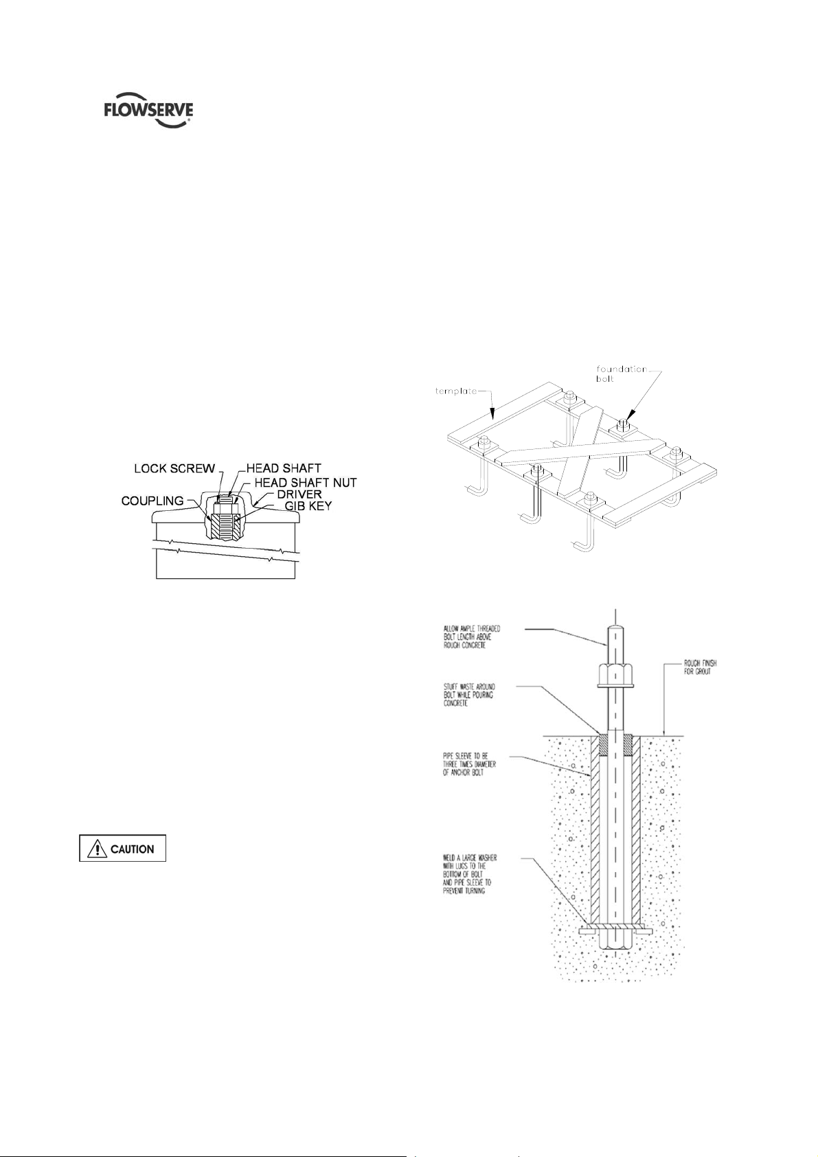
QLQ, QLQC USER INSTRUCTIONS ENGLISH 87900027 – 06/14
Check the packing slip to see if a guide bushing is
required, if so, determine if the bushing is already
mounted or not and proceed accordingly. Refer to
motor instruction manual.
j) Carefully install drive clutc h on driver making sure
that it fits down properly.
k) Clean threads on top of head shaft and head shaft
nut. Lubricate male threads lightly. Install head
shaft.
l) Install gib key in clutch and shaft. This must be a
sliding fit and may require filing and dr essing. Do
not force.
m) Thread adjusting nut down on shaft until it bears
against clutch. (Threads on 43 mm (1.68 in.) and
larger head shaft adjusting nuts are left-handed
and all others are right handed). Do not thread nut
further at this time. See impeller adjusting
instructions in section 5.3.
The most satisfactory foundations are made of
reinforced concrete. These should be poured well in
advance of the installation to allow sufficient time for
drying and curing.
The General Arrangement Drawing (In Job’s User
Instruction) will furnish overall outline of pump
foundation plate, anchor bolt locations, size of bolts,
etc. in order to provide proper shape to the primary
concrete. Anchor bolts can be positioned or by a
special template (not supplied by FLOWSERVE see
figure 4.2) or by the foundation itself if proper pockets
have been provided in primary concrete.
Figure 4.1
4.2 Part assemblies
Motors may be supplied separately from the pumps.
It is the responsibility of the installer to ensure that
the motor is assembled to the pump and aligned as
detailed in section 4.5. Discharge head column piping
and the pump assembly are supplied either
separately or as fully assembled depending upon the
pump size and weight. If the parts are shipped
separately, it is the customer’s responsibility to install
and align the pump with driver to the satisfaction of
Flowserve’s installation instructions.
4.3 Foundation
There are many methods of installing
pump units to their foundations. The correct method
depends on the size of the pump unit, its location and
noise vibration limitations. Non-compliance with the
provision of correct foundation and installation may
lead to failure of the pump and, as such, would be
outside the terms of the warranty.
The foundation should be sufficiently rigid and
substantial to prevent any pump vibration and to
permanently support the baseplate at all points.
Template for Hanging Foundation Bolts
Figure 4.2
Figure 4.3
Page 23 of 61
Page 24

QLQ, QLQC USER INSTRUCTIONS ENGLISH 87900027 – 06/14
Figure 4.3 illustrates an alternative foundation bolt
arrangement which can be used in lieu of standard
foundation bolts. Notice the large washer with lugs at
the bottom. It should be welded to the bolt and pipe
sleeve to prevent turning.
Allow a little more than the specified threaded bolt
length above the rail of the foundation plate. The
excess can always be cut off if it is not needed.
A rough finish top surface is best when applying
grout.
4.3.1 Leveling of pumps with suction barrel
4.3.1.1 Pumps equipped with foundation plate
Figure 4.4
The soleplate is installed on the foundation and
aligned with the anchor bolts. Level the soleplate
with the help of a machinist’s level to within 0.25 mm
per m (0.0035 in. per ft.). Grout the plate. Cu re and
allow grout to set for 72~80 hours. Tighten the nuts
Lower the suction barrel into the pit and level again
with respect to the soleplate to within 0.25 mm per m
(0.0035 in. per ft.). The pump is now lowered into the
suction barrel and installed.
4.3.1.2 Pumps equipped without foundation plate
DISCHARGE
HEAD FLANGE
CONCRETE
FOUNDATI ON
Figure 4.5
The suction barrel is first lowered into the pit and
aligned with the anchor bolts. The suction barrel flange
is leveled by using a master level or a precision
machinist’s level. Levels should be taken on the
equipment mounting surfaces. The suction barrel
flange mounting surface needs to be leveled to within
0.25 mm per m (0.0035 in. per ft.) using shims and
grouted. Allow the grout to set for at least 72~80 hours
before the pump is installed. Check the barrel
mounting surface level after the grout is set and then
proceed with the pump installation. Lower the pump
assembly into the pit and align the discharge head
flange bolt holes to the anchor bolts.
4.3.2 Leveling of pumps in wet pit (sump)
4.3.2.1 Pump equipped with support beams
Some pumps are mounted on two beams supporting
the suction head. The beams are fixed through bolts
to plates, that need to be grouted, that act as
soleplate.
Page 24 of 61
Figure 4.6
Page 25

QLQ, QLQC USER INSTRUCTIONS ENGLISH 87900027 – 06/14
The two plates are installed on the foundation and
aligned with the anchor bolts. Level the plates with
the help of a machinist’s level to within 0.25 mm per
m (0.0035 in. per ft.). Grout the foundation plates.
Allow the grout to set for at least 72~80 hours before
the pump is installed Tighten the nuts.
Proceed according the procedure described in
section 4.1.4.2.
4.3.2.2 Pump equipped with foundation plate
DISCHARGE
HEAD FLANGE
SOLE
CONCRETE
FOUNDATION
Figure 4.7
PLATE
Some pumps are mounted on a sepa ra t e plate kn ow n
as soleplate. In such cases, the level shall be set with
a master level or a precision machinist’s level. The
mounting surface needs to be leveled to within 0.25
mm per m (0.0035 in. per ft.) using shims and
grouted.
Accurate shimming and grouting of the soleplate is
very important. Record the leveling data for future
reference. Grout the soleplate an d allow to set at least
72~80 hours (cure as required) before the pump is
lowered into the pit. Align the discharge head bolt
holes with the anchor bolts. torque the nuts to the
required level.
4.3.2.3 Pump equipped without foundation plate
HEAD FLANGE
Some wet pit pumps are installed directly by using
the flange that comes as an integral part of the
discharge head. The pump is lowered into the pit and
aligned with the anchor bolts.
The mounting flange is shimmed to achieve required
level by using a precision machinist’s level. The
pump is to be leveled to within 0.25 mm per m
(0.0035 in. per ft.). The data to be recorded for future
reference. Anchor bolt nuts are tightened sufficient
enough to hold down the pump in place.
Grout is poured and allowed to set for at least 72 ~80
hours (cure as required) before any further work is
done on the pump.
If leveling nuts are used to level the
base, they must be backed off a s far as possible prior
to grouting.
Always shim near foundation bolts and then back off
the leveling nuts. Now tighten the foundation bolts. If
done otherwise ther e is a risk of signific antly lowering
the structural natural frequency that could result in
separation of the base from the grout.
Directly mounted pumps are not user
friendly for service. Re-installation of these pumps
requires re-leveling and re-grouting.
4.4 Grouting
Where applicable, grout in the foundation bolts.
After adding pipe work connections and re-checking
the coupling alignment, the mounting plate/soleplate
should then be grouted in accordance with good
engineering practice. If in a ny doubt, please contact
Flowserve service center for advice.
Grouting provides solid contact between the pump
unit and foundation that prevents lateral movement of
running equipment and dampens resonant vibrations.
CONCRETE
Figure 4.8
Foundation bolts should only be fully
tightened after the grout has been cured.
Page 25 of 61
Page 26

QLQ, QLQC USER INSTRUCTIONS ENGLISH 87900027 – 06/14
4.5 Initial alignment
4.5.1 Thermal expansion
The pump and motor will normally
have to be aligned at ambient temperature and
should be corrected to allow for thermal expansion at
operating temperature. In pump installations involving
high liquid temperatures, the unit should be run at the
actual operating temperature, shut down and the
alignment checked immediately.
4.5.2 Preparation before alignment
To ensure proper alignment the following items are
very important.
a) All machined mating surfaces (such as the
mating flanges of pump and motor) must be
clean and free of burrs and nicks.
b) Exterior strain must not be transmitted to the
pump. The most common cause of trouble is
forcing the piping to mate with the pump. It is
recommended that flexible connectors be installed
in the piping adjacent to the pump.
c) All threads should be checked for damage and
repaired if necessary. Lubricate all threaded
connections with a suitable thread lubricant (an
anti-galling compound).
4.5.3 Alignment methods
Ensure pump and driver are isolated
electrically and the half couplings are disconnected.
The alignment MUST be checked.
Although the pump will have been aligned at the
factory it is most likely that this alignment will have
been disturbed during transportation or handling.
If necessary, align the motor to the pump, not the
pump to the motor.
4.5.3.1 Shaft./Coupling alignment
Shaft alignment must be correct for
successful operation. Rapid wear, noise, vibration
and actual damage to the equipment may be
caused by shaft misalignment. The shafts must
be aligned within the limits given within this
section.
Adjustment to correct the alignment in one
direction may alter the alignment in another direction.
Always check in all directions after making any
adjustment.
Coupled equipment must be aligned to minimize
unnecessary stresses in shafts, bearings and
coupling. Flexible couplings will not compensate for
appreciable misalignment. Foundation settling,
thermal expansion or nozzle loads resulting in
baseplate/foundation deflection and vibration during
operation may require the full coupling misalignment
capability.
4.5.3.2 Types of misalignment
There are two types of shaft misalignment: angular
and offset. Therefore, two sets of measurements and
corrections are required. Both types of misalignment
can occur in horizontal and vertical planes and are
present in most applications.
a) Angular misalignment
In angular misalignment, the center line of the shafts
intersect, but are not on the same axis.
The motor assembly has to be adjusted in
the horizontal direction to line up the dr iver and shaft
centers. Alignment screws are provided to lock the
motor assembly in its final aligned position.
See section 5.3.2.1 for final coupling alignment for
solid shaft.
Check the direction of pump rotation
before the coupling is fully connected. The power
supply to the driver to be connected only after the
final alignment is complete.
Page 26 of 61
Figure 4.9
b) Offset misalignment
In offset misalignment, the shaft center lines are
parallel but do not intersect.
Figure 4.10 – offset misalignment
Page 27

QLQ, QLQC USER INSTRUCTIONS ENGLISH 87900027 – 06/14
Figure 4.11 – combination of offset and angular misalignment
4.5.3.3 Alignment of flex coupling
For flexible couplings with narrow flanges use a dial
indicator as shown in figure 4.12 to check both
parallel and angular alignment.
For detailed alignment procedure refer to API RP686.
Figure 4.12
Maximum permissible misalignment at working
temperature:
Parallel 0.05 mm (0.002 in.) TIR
Angular 0.05mm/100mm (0.0005In/In)
4.5.3.4 Alignment of rigid coupling
Place the indicator of the machined surface of the
stuffing box.
If the pump is equipped with a packing seal, a 2halved ring is provided to be inserted in the stuffing
box to keep the shaft centered in the correct position
Figure 4.13
Maximum permissible misalignment at working
temperature:
Parallel 0.05 mm (0.002 in.) TIR
Angular 0.05mm/100mm (0.0005In/In)
a) Pumps with thick flanged non-spacer couplings
can be aligned by using a straight-edge across
the outside diameters of the coupling hubs and
measuring the gap between the machined fac es
using feeler gauges, measuring wedge or
calipers.
b) When the electric motor has sleeve bearings, it is
necessary to ensure that the motor is aligned to
run on its magnetic centerline.
c) Refer also to section 4.1.6 for alignment of
pumps with both mechanical seal and thrust
bearing.
Refer to the motor User Instructions for details.
A button (screwed into one of the shaft ends) is
normally fitted between the motor and pump shaft
ends to fix the axial position.
If the motor does not run in its
magnetic center the resultant additional axial force
may overload the pump thrust bearing.
If the pump is handling hot liquid, the alignment must
be rechecked in warm condition of the unit. The
alignment of the unit shall be checked again after 200
service hours.
Page 27 of 61
Page 28

QLQ, QLQC USER INSTRUCTIONS ENGLISH 87900027 – 06/14
Complete piping as below and see sections up
to and including section 5, “Commissioning, startup,
operation and shutdown” before connecting driver
and checking actual rotation.
Once the alignment has been completed,
proceed dowelling the motor stand to the discharge
head.
4.6 Piping
Never use the pump as a support for
piping.
Protective covers are fitted to the pipe
connections to prevent foreign particles or objects
entering the pump during transportation and
installation. Ensure that these covers are removed
from the pump before connecting pipes.
4.6.1 General
These units are furnished for a particular service
condition. Changes in the hydraulic system may
affect performance adversely. This is especially true if
the changes reduce the pressure at the suction or if
the liquid temperature is increased. In case of doubt
contact FLOWSERVE.
Discharge and suction (if installed) piping should be
of ample size, be installed in direct runs, and have a
minimum of bends. Double bends must be avoided in
suction line and a straight run of pipe, equ al 8 to 10
times the pipe diameter is desired directly upstream
of the suction nozzle.
In order to minimize friction losses and hydraulic
noise in the pipework it is good practice to choose
pipework that is one or two sizes larger than the
pump suction and discharge. Typically main pipework
velocities should not exceed 2 m/s (6 ft./sec) suction
and 3 m/s (9 ft./sec) on the discharge.
Provision must be made to support piping
external to the pump to prevent excessive nozzle
loads, maintain pump/driver alignment and avoid pipe
induced vibrations.
Take into account the available NPSH which mu st be
higher than the required NPSH of the pump.
Maximum forces and moments allowed on the pump
flanges vary with the pump size and type. The
maximum allowable values allowed are stated in the
General Arrangement Drawing provided in the
Instruction Manual Book.
To minimize these forces and moments that may, if
excessive, cause misalignment, hot bearings, worn
couplings, vibration and the possible failure of the
pump casing, the following points should be strictly
followed:
Prevent excessive external pipe load
Never draw piping into place by applying force to
pump flange connections
Do not mount expansion joints so that their force,
due to internal pressure, acts on the pump flange
Ensure piping and fittings are flushed
before use.
Ensure piping for hazardous liquids is arranged
to allow pump flushing before removal of the pump.
4.6.2 Suction piping (if applicable)
a) The inlet pipe should be one or two size s larger
than the pump inlet bore and pipe bends should
be as large radius as possible.
b) Keep the suction pipe free of all air pockets.
(Vent is required).
c) Pipework reducers should have a maximum total
angle of divergence of 15 degrees.
d) The piping should be inclined up towards the
pump inlet with eccentric reducers incorporated
to prevent air locks.
e) Flow should enter the pump suction with uniform
flow, to minimize noise and wear.
f) Except if con siderable foreign matter is expected
strainers are not recommended in inlet piping.
Inlet strainers, when used, should have a net
“free area” (see section 4.6.2.1).
4.6.2.1 Suction strainer
In a new installation, great care should be taken to
prevent dirt, scale, welding beads and other items
from entering the pump, as it is particularly important
to protect the numerous close running fits from
abrasive matter present in new piping.
The suction system should be thoroughly flushed
before installing the suction strainer and making up
suction piping to the pump.
The suction strainer should be installed between 5 to
20 pipe diameters upstream from the pump suction
flange.
The open area of the strainer should
have a minimum of a 3 to 1 ratio to the area of the
pump suction.
Page 28 of 61
Page 29

QLQ, QLQC USER INSTRUCTIONS ENGLISH 87900027 – 06/14
4.6.4.1 Drains
Normal pump leaks and gland leakage are to be
drained through a separate piping arrangement or
back into the suction/sump.
Ensure proper drain in case of hazardous,
flammable or toxic pumped fluid.
4.6.4.2 Pumps fitted with gland packing
Figure 4.14
Cone Type Strainer
The Flowserve recommendation for suction strainers
consists of a conical shaped steel plate. The plate
has 1.6 mm (1/16 in.) perforations and is of sufficient
size and thickness for the required flow. See Figure
above.
Other type of strainers may be used as long as they
conform to the requirements stated above.
The pump is shipped without packing in the stuffing
box. A complete set of packing is shipped in a
separate box attached to the pump crate.
Properly packed stuffing box is a must for efficient
pump operation. Proceed as follow:
a) Clean out the stuffing box.
b) Install three rings of packing at the bottom of the
stuffing box.
c) Insert the lantern ring.
d) Continue adding the required n umber of packing
rings, in accordance with cross section drawing
Pressure gauges should be installed on both sides of
the screen so that the pressure drop across the
screen can be measured.
When the unit is being started, the gauges on each
side of the screen should be carefully watched. An
increase in the differential pressure between the two
gauges indicates that the screen is becoming clogged
with dirt and scale. At this point, the pump should be
shut down, and the screen cleaned and/or replaced.
box at a time, making sure it is properly seated.
e) Stagger the joints of succeeding rings. When the
Install one ring of stuffing box packing in the
last ring is in place, assemble the gland and pull
up the nuts evenly until snug. Then back off the
nuts and re-tighten finger tight.
The stream of leakage following pump startup
can be controlled by taking up the gland nuts. It is
suggested that this is done slowly, one flat at a
time until satisfactorily leakage or lubrication has
A spool piece should be installed in
suction line so that the suction strainer may be
been obtained.
installed and removed with a pressure gauge
between the strainer and pump.
4.6.3 Discharge piping
a) Install a check valve and a gate valve in the
discharge pipe of the pump. When the pump is
stopped, the check valve will protect the pump
against excessive pressure and will prevent the
pump from running backward. The check valve
should be installed between the gate valve and
the pump nozzle in order to permit its inspection.
Never throttle pump on suction side and never
place a valve directly on the pump inlet nozzle.
b) Pip ework reducers should have a maximum total
angle of divergence of 15 degrees.
Take into account the available NPSH that must be
higher than the required NPSH of the pump.
4.6.4 Auxiliary piping
tightened to the point where leakage from the packing
is stopped. A small amount of leakage is required for
lubrication of the packing. Tightening the packing until
stopping the leakage flow from the packing will result
in burning of the packing, scored shaft sleeve and
possible rotor seizure.
4.6.4.3 Pumps fitted with mechanical seals
QLQs pumps can be equipped with single or double
cartridge mechanical seal.
In relation to the different condition of services, type
of fluid and pressures, different seal flushing plans
can be provided.
Refer to the dedicated General Arrangement drawing
included in the Instruction Manual Book to see the
type of flushing plan installed.
Against the dedicated documents, check that the
flushing plan is correctly assembled and secured.
Packing gland must never be
Page 29 of 61
Page 30

QLQ, QLQC USER INSTRUCTIONS ENGLISH 87900027 – 06/14
Connect all the external connections (external
flushing or gas piping, electrical supply and wiring of
instrument (if any) according to what specified in
Section 4.8.
See section 5.4 for Direction of
rotation before connecting motor to the power supply.
If external flushing is needed, ensure
that the external flushing is open and reach the
mechanical seal before starting the pu m p.
4.6.4.4 Other piping
Refer to the pump general arrangement drawing for
location of the auxiliary piping terminal points, such
as packing and bearings washing and hypochlorite
flushing.
4.6.5 Final checks
After connecting the piping to the pump, rotate the
shaft several times by hand to ensure no pipe strain.
If pipe strain exists, correct piping.
4.7 Electrical connections
Electrical connections must be made
by a qualified Electrician in accordance with relevant
local, national and international regulations.
It is important to be aware of the EUROPEAN
DIRECTIVE on potentially explosive areas where
compliance with IEC60079-14 is an additional
requirement for making electrical connections.
It is important to be aware of th e EUROPEAN
DIRECTIVE on electromagnetic compatibility when
wiring and installing the equipment on site. Attention
must be paid to ensure that the techniques used
during wiring/installation do not increase
electromagnetic emissions or decrease the
electromagnetic immunity of the equipment, wiring or
any connected devices. If in any doubt contact
Flowserve for advice.
The motor must be wired in
accordance with the motor manufacturer's
instructions (normally supplied within the terminal
box) including any temperature, ground leakage,
current and other protective devices as appropriate.
The identification nameplate should be checked to
ensure the power supply is appropriate.
A device to provide emergency stopping must
be fitted to the system.
If not supplied pre-wired to the pump unit, the
controller/starter electrical details will also be supplied
within the controller/starter.
For electrical details on pump sets with controllers
see the separate wiring diagram sent along with the
pump. If no such document is found, please call
Flowserve and request for prints.
Page 30 of 61
Page 31

QLQ, QLQC USER INSTRUCTIONS ENGLISH 87900027 – 06/14
4.8 Protection systems
The following protection systems are
recommended particularly if the pump is installed in a
potentially explosive area or is handling a hazardous
liquid. If in doubt, consult Flowserve.
If there is any possibility of the system allowing the
pump to run against a closed valve or below
minimum continuous safe flow a protection device
should be installed to ensure the temperature of the
liquid does not rise to an unsafe level.
If there are any circumstances in which the system
can allow the pump to run dry, or start up empty, a
power monitor should be fitted to stop the pump or
prevent it from being started. This is particularly
relevant if the pump is handling a flammable liquid.
If leakage of product from the pump or its associated
sealing system can cause a hazard it is
recommended that an appropriate leakage detection
system is installed.
To prevent excessive surface temperatures at the
bearings, it is recommended that temperature an d/or
vibration monitoring is done on a regular basis.
Page 31 of 61
Page 32

QLQ, QLQC USER INSTRUCTIONS ENGLISH 87900027 – 06/14
5 COMMISSIONING, STARTUP,
OPERA TION AND SHUTDOWN
These operations must be carried out
by fully qualified personnel. Turn off power supply for
safety while pump commissioning is in progress.
5.1 Pre-commissioning procedure
The gland is to be filled with grease and flush supply
to be in place. Flush piping to be checked for leaks.
Mechanical seals to be checked for leaks, flush flow
and pressure.
a) Pumps with the enclosing tubes and oil-lubed
bearings must be filled with the proper lubricant to
avoid running dry and to guarantee acceptable
performance of the pump. A separate oil tank is
attached to the pump (see detail in section 5.2.2).
b) For can pumps check all vent connections for
complete filling of the pump. The venting procedure
can take from 10 minutes up to 2 hours, depending
on the kind of fluid (except cryogenic servic e).
c) Check the direction of rotation of the pump
(Coupling spacer dismantled). Should be counter
clockwise when viewed from the driver end.
d) The pump rotor and the shaft seal must be in
correct axial position.
e) Check the readiness of all auxiliary systems (seal
sys., lubrication system etc.,) for sta rtup.
f) All pipe work in clu di n g the internal and the auxiliary
pipe work must be connected correctly and must
be absolutely tight. Check the tightness of all
connections of the auxiliar y pipe wor k. The suc tion
valve must be open, the discharge valve shall be
closed or partially open as required.
g) Turn the pump by hand, if required with the help of
a lever, to check the free rotation of the rotor. The
rotor must turn uniformly and noiselessly. Some
resistance may be felt due to the friction in the
bearings and seals.
h) Check the readiness of the driver for startup. Refer
to the manual for the driver to be sure that all
precautions are in place to energize the motor.
5.2 Pump Lubricants
Re-checking the motor lubrication should
be in accordance with the motor manufacturer’s user
instructions supplied separately with the pump.
5.2.1 Open lineshaft lubrication
Open lineshaft bearings are lubricated by the pumped
fluid on short-coupled units less than 15 m (50 ft.) long
and will usually not require pre or post-lubrication.
Care is to be taken to ensure that the gland or seal is
supplied with the required flush flow.
All open lineshaft pumps where the static water level is
more than 15 m (50 ft.) below the discharge head
should be adequately pre-lubricated before starting the
pump.
Pre-lubrication shall be provided either by pumped
fluid (through a special piping fitted on the discharge
head, to be connected to the discharge piping) or by
clean external source (water or oil) fro m au xiliar y lin es
or dedicated tank.
Refer to the specific description on the dedicated
documents of the pump.
It is the responsibility of the User to install a
reliable pre- lube system to achieve the pump prelubrication. Flowserve will not supply these types of
systems or accessories with the pump, unless
otherwise agreed.
5.2.2 Enclosed shaft lubrication
QLQs with the enclosed shafting are lubricated by a
dedicated oil supply system or injection lubricated by
extraneous liquid; usually clean water to meet the
application requirements.
On water pumps, the suction bearing on the bowl
assembly should be repacked when required. Pumps
that pump hydrocarbons or have carbon, rubber,
epoxy or Teflon suction bearings do not have the
suction bearings packed. If the pump will be started
after a longer storage period, the bearings sho uld be
first flushed and cleaned by using a suitable cleaning
agent. It is not necessary to remove the oil spr ayed
for short or long-term storage as this will mix up
thoroughly with the lubrication oil.
5.2.2.1 Oil lubricated pumps
The lubricating oil must be available and should be
allowed to run into the enclosing tube in sufficient
quantity to thoroughly lubricate all lineshaft bearings.
The gravity flow system is the most commonly utilized
system for oil.
The oil reservoir (example shown in detail below)
must be kept filled with a good quality light turbine oil
(about 30 cSt) at the operating temperature and
adjusted to feed a minimum of 3 drops per minute per
30 m (100 ft.) of column length, bu t not to exceed 5
drops per minute.
Page 32 of 61
Page 33

QLQ, QLQC USER INSTRUCTIONS ENGLISH 87900027 – 06/14
Food grade lubricant oils
Oil Manufacturer Trade name of the oil
Exxon Company Exxon-DTE-FM32
Mobil Oil Company Mobile DTE-FM- Grade- 32
Shell Oil Company Cassida HF 32
If none of the above oils are available, equivalent
turbine oil (food or non-food gr ades as required) with
5.2.2.1.1 Pre-lubrication of oil lubricated pumps
As a general rule, the oil must be allowed to flow by
gravity at least 45 minutes before the pump is started
for the first time or in case the pump was turned off
for a longer duration. Adequate care should be taken
to make sure that the flow is available and is
consistent for subsequent startups.
5.2.2.1.2 Enclosed shaft lubricants
The following oils are recommended for enclosed
lineshaft bearing lubrication under normal operating
the matching properties has to be selected. Oils with a
viscosity range of 30 cSt (mm
2
(mm
/sec) at 40 C (100 F) with a minimum viscos ity
2
/sec) to 37 cSt
index of 90 are recommended.
5.2.2.1.3 Oil level
The correct oil level is in the middle of the oil sight
glass and shall be checked when the pump is not in
operation. Periodically check if the lubricating oil is
mixed with any condensed water. Careful opening of
the oil drain during a stop of the pump will show any
water.
conditions. See following tables.
Oil used for enclosed shaft lubrication should only be
of high quality turbine grade. The viscosity of the oil
at working temperature must be at least 30 cSt
2
/sec).
(mm
The pour point of the oil must be in accordance with
the lowest expected temperature of the bearing
housing during a stop of the pump.
due to circulation of the oil through the bearings.
result in higher bearing temperatures resulting in poor
lubrication.
5.2.2.2 Injection lubricated pumps
Enclosed lineshaft bearings are lubricated by
After the initial start the level will decrease
If the oil level is higher than specified, it could
extraneous liquid (usually clean water), which is fed
It is recommended that detergent type
oils not be used.
to the tension nut either by gravity flow, or by a
pressure injection system.
Non-food grade lubricant oils
Oil Manufacturer Trade name of the oil
Conoco Inc. Conoco Diamond Class Turbine
oil ISO -32
Exxon Company Teresstic- GT 32
Mobil Oil Company Mobile DTE-797- Gr ad e-32
Shell Oil Compa ny Tellus-32, Tellus-37 or Turbo Oil
T -32
Chevron Lubricants Chevron Turbine Oil TR-32
BP Energol HL-C 32
Texaco, Inc. Texaco Regal (R&O)- 32
installation. Injection pressure and quantity of liquid
will vary. Normally 0.45-0.90 m
0.7-1.4 bar (10-20 psi) over maximum pump
discharge pressure of clean liquid is required.
5.2.2.2.1 Pre-lubrication of injection lubricated pumps
As a general rule, the liquid flow is to be started at
least 15~20 minutes before the pump is started for
the first time or in the event of pump not being in use
for longer duration.
The injected lubricant flow is never stopped for short’
off’ periods. Adequate care should be taken to make
Injection systems are designed for each
3
/h (2-4 USgpm) at
sure that the flow is available and consistent
oils not be used.
Page 33 of 61
It is recommended that detergent type
Page 34

QLQ, QLQC USER INSTRUCTIONS ENGLISH 87900027 – 06/14
5.3 Lubrication of thrust bearing
If the thrust bearing is installed in the pump, it must
be supplied properly with lubricant oil.
5.3.1 Grade of Oil
Oil for lubricating ball or roller should be a high
quality, well refined mineral oil preferably of the
turbine type. Vegetable or animal oils should not be
used as they tend to become rancid and will
eventually corrode the bearing surface.
Oil should conform to specification ISO VG46. The
following suppliers grade are suitable.
Oil Manufacturer Trade name of the oil
AGIP OTE 46
BP Oil Ltd Energol THB 46 or CS 46
CASTROL Perfecto T46
CHEVRON DC Turbine Oil 46
ESSO Teresso 46 or Nuto H46
GULF Harmony 46
MOBIL DTE Light
SHELL Turbo T46
TEXACO Regal Oil R&O 46
5.3.2 Oil Filling
a) Dr ain the bearing bracket and flush it with a light
oil. Install the constant level oiler.
b) Make sure the oiler is set at proper level.
c) Fill the bottle through the stem, replace and allo w
oil to flow into reservoir. It may be necessary to
fill the bottle several times before the oil ceases
to run into the reservoir, indicating that the oil is
up to the proper level.
d) Refill the bottle to maintain this level.
Never fill the reservoir through the air
vent opening.
5.3.3 Constant Level Oil Control
The constant level oil control maintains a constant
level of oil in the reservoir. The control feeds only
enough oil to maintain the required level. It operates
on the liquid seal principle, feeding only when the
level in the reservoir is low enough to break the liquid
seal at the end of the shank, thus permitting air to
enter the bottle. It will cease to feed when there is
sufficient oil in the reservoir to cover the hole in the
end of the shank.
Constant level oiler
5.3.4 Bearing Oil Temperature
Circulation of the oil in the reservoir is achieved by
centrifugation. It is recommended that the lubricating
oil is kept between 38°C and 75°C (100°F-167°F),
preferably above 49°C (120 °F).
The bearing oil temperature without cooling may rise
to 82°C (180 °F).
5.3.5 Oil Change
Operating conditions and severity of service will
determine the interval between oil changes. In
general higher oil temperature will require more
frequent oil change. If the bearings maintain their
normal temperature and there has been no
contamination of the oil, the interval between
changes may be prolonged.
Generally the oil should be changed every six
months. If the bearing temperature increases, check
immediately improper lubrication or a faulty bearing.
5.4 Impeller adjustment
Proper impeller adjustment is needed to place the
impeller inside the bowl assembly in the best position
to maximize performance. If the impeller position i s not
fitted, a reduction in performa nces shall occur , and , in
the worst cases, impeller and casing damages by the
contact between casing and impeller.
5.4.1 Impeller adjustment of a pump with solid
shaft driver
During pump assembly in factory, the pump shaft is
axially positioned by the adjusting nut so that the
impeller is centered in the correct position.
Check after the installation and regulate the position
of the impeller, even if the pump has been installed
completely assembled.
Page 34 of 61
Page 35

QLQ, QLQC USER INSTRUCTIONS ENGLISH 87900027 – 06/14
a) With the pump completely installed, proceed
installing the hubs of the rigid coupling (thrust
bearing side and pump side ).
b) Lift the pump rotor till its upper position and
record the vertical distance from a reference
point.
c) Release the rotor to its lower position, and record
again the position form the same reference point
d) The pump rotor shall have an axial run of
5÷10mm (0.2÷0.4 inches). If the recorded run is
different form this range, re- check the installation
and pump assembly.
e) By rotating the screwed collar installed on the
pump coupling hub, position the rotor at the
middle of the run (half the value from the top and
the bottom measured).
f) Proceed aligning the hubs according to section
5.3.2.
The position of the regulating nut is located
on the rigid coupling. If the rigid coupling is not
installed, the impeller adjustment shall be done
through the regulating nut placed at the top of the
bearing house. Refer to the dedicated Cross
Sectional drawing supplied with the IOM book to
identify where the adjusting impeller nut is located.
5.4.2 Impeller adjustment for a hollow shaft
driver
Impeller adjustment when using hollow shaft drivers is
as follows. The driver canop y will ha ve to be r emoved
before beginning.
a) Install headshaft if not already in place.
b) Install driver clutch in accordance with the driver
instruction manual and bolt into place.
c) Check shaft position. Lower shaft until there is a
definite feel of metal contacting metal. This
indicates the impellers are "on bottom" and in the
correct starting position for impeller adjustment.
d) Thread headshaft nut down (right hand threads)
except 43 mm (1.7 in.) and larger sizes that are
having left hand threads, until impellers are just
raised off their seat and the shaft will rotate freely.
e) Check a separate document that is supplied with
the pump that provides recommended impeller
setting and running clearance information.
Detail showing head shaft and lock screw arrang ement
If at any time during the life of this pump the
pumping conditions or total pump length changes,
contact the factory for recalculation of the impeller
setting.
f) Tighten the adjusting nut to match impeller setting
recommended by Flowserve.
g) Using the ca p screw provided, bolt the headshaft
nut down & lock using lock screw to the motor
coupling. See the details of head shaft and lock
screw arrangement under item (h) below.
Always lock headshaft nut by
tightening the lock screw before starting driver.
Failure to do so could result in damage to th e pump
and driver.
h) If a mechanical seal is used, adjust the
mechanical seal at this time.
Shafts elongate due to the hydraulic thrust
of the pump and the impellers must be compensated
for this elongation. Shaft elongation varies for each
model depending upon the size, shaft length, shaft
diameter, impeller weight, number of stages. Please
see the documentation supplied along with the pump
for exact impeller setting value matched for the
specific pump that you have purchased.
Page 35 of 61
Page 36

QLQ, QLQC USER INSTRUCTIONS ENGLISH 87900027 – 06/14
5.5 Direction of rotation
Ensure the pump is given the same
rotation as the pump direction arrow fit on bearing
housing. In any case the direction of rotation must be
checked with the pump disconnected.
To avoid dry running the pump must either be filled
with liquid or have the flexible coupling disconnected
before driver is switched on.
If maintenance work has been carried
out to the site's electricity supply, the direction of
rotation should be re-checked as above in case the
supply phasing has been altered.
5.6 Guarding
Guarding is supplied fitted to the pump set by
captive fasteners. If this has been removed or
disturbed ensure that all the protective guards around
the pump coupling and exposed parts of the shaft are
securely fixed.
Machinery to be protected at all times by Flowserve
provided safety guards or per applicable local or
national standard. Compliance is mandatory for som e
regions of the world and in explosive environm ents .
5.7 Priming and auxiliary supplies
Ensure electrical, hydraulic,
pneumatic, sealant and lubrication systems (as
applicable) are connected and operational.
Ensure the inlet pipe and pump casing
are completely full of liquid before starting continuous
duty.
(For Wet Pit application) Ensure that
the pump has the required Minimum Submergence
according to the value stated on the dedicated
General Arrangement Drawing.
5.8 Starting the pump
Ensure flushing and/or cooling/
heating liquid supplies are turned ON before
starting the pump.
a) CLOSE the outlet valve (or partially open in s ome
cases).
b) OPEN all inlet valve.
c) For wet pit application check that the liquid le vels
are correct; for can pumps, ensure that the can is
filled with liquid before starting the pump
d) Ensure all vent connections are closed
before starting.
e) Check the motor connections.
Do not run the pump with the outlet
valve closed for a period longer than 30 seconds.
5.8.1 Pre-starting checks
Before starting the pump the following checks should
be made.
b) Rotate the pump shaft by hand to make sure the
pump rotates freely and the impellers are
correctly positioned.
c) Has the electric motor been properly lubricated in
accordance with the instructions furnished with
the driver?
d) Has the electric motor been checked for proper
rotation? If not, the pump must be disconnected
from the driver at the coupling before checking.
The electric motor must rotate counter-clockwise
when looking down on the top of the driver.
e) Check all connections to the driver and control.
Do not overfill the grease cavity. Over greasing
can lead to failure of the thrust bearing.
f) Check that all piping connections are tight.
g) Check all foundation bolts for tightness.
h) Check all bolting connections for tightness
(coupling bolts, mechanical seal gland bolts,
driver bolts etc.).
i) Make sure the mechanical seal is properly
adjusted and locked into place. Ensure that all
seal spacers are in the running position prior to
operation.
j) All guards must be secured in position prior to
pump startup to prevent possible contact with
rotating parts.
To ensure proper alignment three items are very
important during installation an d the y are:
All machined mating surfaces (such as the
mating faces of the pump and motor) must be
clean and free from burrs and nick s.
These surfaces should be cleaned thoroughly
with a scraper, wire brush and emery cloth if
necessary and all nicks or burrs removed with a
fine file.
Exterior strain must not be transmitted to the
pump. The most common cause of trouble in
this respect is forcing the piping to mate with the
pump. It is recommended that flexible
connectors be installed in the piping adjacent to
the pump.
Page 36 of 61
Page 37

QLQ, QLQC USER INSTRUCTIONS ENGLISH 87900027 – 06/14
All threads should be checked for damage and
repaired if necessary. If filing is necessary,
remove the part from the pump if possible, or
arrange to catch all the filings so they do not fall
onto other parts of the pump. Clean all threads
with a wire brush and approved cleaning solvent,
ends of shafts must be cleaned and any burrs
removed since alignment depends on the shaft
ends butting squarely. Lubricate all threaded
connections with a suitable approved thread
lubricant (an approved anti-galling compound
should be used on stainless mating threads).
k) On pumps equipped with mechanical seals, clean
fluid should be put into the seal chamber. With
pumps under suction pressure, this can be
accomplished by bleeding all air and vapor out of
the seal chamber and allowing the fluid to enter.
With pumps not under suction pressure, the seal
chamber should be flushed liberally with clean fluid
to provide initial lubrication. Make sure the
mechanical seal is properly adjusted and locked
into place. Insure that all seal spacers are
removed prior to operation.
l) On pumps equipped with thrust bearing in the
pump, ensure that the thrust bearing support is
filled with the correct level of oil, by checking the
level through the sight g lass. If the thrust bearing
has the cooling water installed, check that the
flush if cooling water is turned on before starting
the pump.
m) If provided, check that the external flushing of the
mechanical seal is turned on.
5.8.1.1 Typical safety guards
GUARDS
INS T A L L E D
A screen guard is furnished with all pumps
having a two-piece headshaft or an adjustable
flanged coupling. This screen must be secured in
place prior to pump startup to prevent possible
contact with rotating parts. Typical arrangement is
shown in section 5.8.1.1.
5.8.2 Stuffing box adjustment (if installed)
On the initial starting it is very important that the
packing not be tightened excessively. New packing
must be run in properly to prevent da ma ge to the sh aft
and shortening of the packing life.
The stuffing box must be allowed to leak for proper
operation. The proper amount of leakage can be
determined by checking the temperature of the
leakage, this should be cool or just lukewarm - NOT
HOT - usually 40 to 60 drops per minute will be
adequate.
When adjusting the packing gland, bring both nuts
down evenly and in small steps until the leakage is
reduced as required. The nuts should only be
tightened about one half turn at a time at 20 to 30
minute intervals to allow the packing to "run-in".
Under proper operation, a packing set will last a long
time. Occasionally a new ring of packing will need to
be added to keep the box full.
Page 37 of 61
Page 38

QLQ, QLQC USER INSTRUCTIONS ENGLISH 87900027 – 06/14
After adding two or three rings of packing, or when
proper adjustment cannot be achieved, the stuffing
box should be cleaned completely of all old packing
and re-packed.
5.8.3 Open shaft lubrication before startup
Open lineshaft bearings are lubricated by the pumped
fluid on short-coupled units less than 15 m (50 ft.)
long and usually do not require pre- or postlubrication. All open lineshaft pumps where the static
water level is more than 15 m (50 ft.) below the
discharge head should be adequately pre-lubricated
before startup.
5.8.4 Enclosed shaft lubrication before start up
Enclosed lineshaft bearings are lubricated by an
extraneous liquid (usually oil or clean water).
The oil reservoir must be kept filled with a good
quality of light turbine oil (about 30 cSt (mm
2
/sec) at
operating temperature) and adjusted to feed 3
drops/minute for every 30 m (100 ft.) of column.
Injection systems are designed for each installation.
Injection pressure and quantity of lubricating liquid
will vary. Usually 0.45 to 0.90 m
3
/h (2 to 4 gpm) at
0.7 to 0.14 bar (10 to 20 psi) over maximum pump
discharge pressure of clean liquid is required.
For recommended oils for enclosed lineshaft bearing
lubrication under normal operating conditions, please
see tables 5.2.3.1 and 5.2.3.2. If none of the above
oils are available, oil with the following specifications
should be obtained. Turbine type oil with rust and
oxidation inhibitors added, viscosity 30 cSt (mm
to 37 cSt (mm
2
/sec) at 37.8 C (100 F) with a
2
/sec)
minimum viscosity index of 90.
In the case of product-lubricated
bearings, the source of product supply should be
checked against the order. There may be
requirements for an external clean supply, particular
supply pressure or the commencement of lubrication
supply before pump startup.
5.8.5 Initial Starting
a) If the discharge line has a valve in it, it should be
partially open for initial starting. The discharge
valve is intended to add sufficient system
resistance to the pump. Failure to maintain pump
flow rates within the limits of the pump and motor
could result in severe damage.
b) Start pre-lubrication liquid flow on pump if
required.
c) Start flushing of mechanical seal through external
sources, if required.
d) Start the pump and observe the operation. If
there is any difficulty, excess noise or vibration,
stop the pump immediately and refer to the
Trouble Shooting Chart (section 7.0) to determine
the probable cause.
Observe extreme caution
when venting and or draining hazardous liquids.
Wear protective clothing in the presence of caustic,
corrosive, volatile, flammable or hot liquids. Do not
breath toxic vapors. Do not allo w sparking, flames or
hot surfaces in the vicinity of the equipment.
Ensure that the unit is vented of all trapped vapor
Open the discharge valve as desired to operate
the unit at its design conditions
Check complete pump and driver for leaks, loose
connections, or improper operation
If possible, the pump should be left running for
approximately one half hour on the initial startup, this
will allow the bearings, packing or seals, and other
parts to "run-in" and reduce the possibility of trouble
on future starts.
If abrasives or debris are present,
upon startup, the pump should be allowed to run until
the pumpage is clean. Stopping the pump when
handling large amounts of abrasives (as is
sometimes present on initial starting) may lock the
pump and cause more damage than the pump is
allowed to continue operation.
Every effort should be made to keep abrasives out of
lines, sump, etc. so that abrasives will not enter the
pump.
In the case of product lubricated
bearings the source of product supply should be
checked against the order. There may be
requirements for an external clean supply, particular
supply pressure or the commencement of lubrication
supply before pump startup.
5.8.6 Frequency of lubrication
The characteristics of the installation and severity of
service will determine the frequency of lubrication.
Lubricant and pump/motor bearing temperature
analysis is useful in optimizing lubricant change
intervals.
Page 38 of 61
Page 39

QLQ, QLQC USER INSTRUCTIONS ENGLISH 87900027 – 06/14
The motor bearing temperature limitations should be
considered for its lubrication requirements. Refer to
the driver manufacturer’s user instructions supplied
with the pump. If documents are not found contact
Flowserve.
For thrust bearing lubrication, please refer to Section
5.3 of this manual.
Never mix greases containing different
bases, thickeners or additives.
5.8.7 Normal vibration levels, alarm and trip
Pumps generally fall under classification of rigid
support machines within the International Rotating
Machinery standard and maximum vibration levels
are based on those standards.
Vibration shall be recorded placing the
accelerometers on the thrust bearing house. If the
pump is not equipped with thrust bearing, vibration
shall be taken placing the accelerometers on the
flange joining the pump head and the driver.
Here below you can find the sketch indicating the
measurement points, according to API 610 standard.
To compare the vibration levels during the
pump life and with the recorded level during factory
acceptance test, the points of measurement shall be
kept according to the sketch below.
Measuring vibration levels in other points will make
the level not comparable.
Alarm and trip values for installed
pumps should be based on the actual meas urements
(N) taken on the pump in a fully commissioned (new)
condition. Measuring vibration at regular intervals
and recording will help to track any deterioration in
pump or operating conditions.
5.8.7.1 Typical allowable field vibration values
According to Flowserve experience, the following
values can be taken as a guideline to set the
alarm/trip of the pumps.
Up to 7 mm/s RMS (0.275 in/sec RMS): vibration
level acceptable
Between 11 and 12 mm/s RMS (0.43-0.47 in/sec
RMS) the pump must be trip
These values are referred to the
measurement taken according to API requirements
(see above). Measurement taken on the motor
bearings ( DE or NDE) will result in higher values.
5.8.8 Motor start/stop frequency
Even though motors ar e normal ly suitab le for a t least
two consecutive starts, it is recommended to restart
only after coasting to rest between starts (minimum of
15 minutes gap), with the motor initially at ambient
temperature. If more frequent starting is necessary,
refer to driver manufacturer’s instructions or contact
Flowserve with details.
The number of motor start and stops
in any given time affects motor life.
starts in any given time, please refer to the driver’s
user instructions before the pump is put into
operation.
If the motor is expected to experience multi
5.9 Running or operation
5.9.1 Venting the pump
Make sure that the pump is vented to enable
all trapped air to escape, taking due care with the
hazardous or hot liquids. Under normal conditions
after the pump is fully vented and primed, it should be
unnecessary to re-vent the pump.
Page 39 of 61
Page 40

QLQ, QLQC USER INSTRUCTIONS ENGLISH 87900027 – 06/14
5.9.2 Pumps fitted with packed glands
If the pump has a packed gland, there must b e some
leakage from the gland. Gland nuts should initially be
finger-tight only. Leakage should take place soon
after the stuffing box is pressurized.
The gland must be adjusted evenly to give
visible leakage and concentric alignment of the gland
ring to avoid excess temperature. If no leakage takes
place, the packing will begin to overheat.
If overheating takes place, the pump should be
stopped and allowed to cool before being re-started.
When the pump is re-started, check to ensure
leakage is taking place at the packing gl and .
If hot liquids are being pumped it may be necessary
to loosen the gland nuts to achieve leakage.
The pump should be run for 30 minutes with steady
leakage and the gland nuts tightened by 10 degrees
at a time until leakage is reduced to an acceptable
level, normally a minimum of 40-60 drops per minute
is required.
Care must be taken when adjusting the gland
on an operating pump. Safety gloves are essential.
Loose clothing must not be worn to avoid being
caught by the pump shaft. Shaft guards must be
replaced after the gland adjustment is complete.
Never run gland packing dry, even for
a short time.
5.9.3 Pumps fitted with mechanical seal
Mechanical seals require no adjus tm ent.
Before pumping dirty liquids, it is advisable, if
possible, to run in the pump mechanical seal using
clean liquid to safeguard the seal face.
External flush or quench should be
started before the pump is run and allowed to flow for
a period after the pump has stopped.
Never run a mechanical seal dry, even
for a short time.
5.9.4 Pump and motor bearing temperature
If the pumps are working in a potentially
explosive atmosphere, temperature or vibration
monitoring at the bearings is recommended.
If pump bearing temperatures (such as thrust
bearings) are to be monitored it is essential that a
benchmark temperature is recorded at the
commissioning stage and after the bearing
temperature has stabilized. Typical alarm set:
set the alarm at 80 °C (180 °F) and the trip at 90
°C (194 °F) for high ambient temperature and/or
hot service
When the bearing temperature sensor is provided:
set the alarm at 95 °C (200 °F) and the trip at 105
°C (220 °F)
It is important, particularly with grease lubrication, to
keep a close watch on the bearing temperatures.
After startup the temperature rise should be gra dual,
reaching a maximum after approximately 1.5 to 2
hours. This temperature should then remain constant
or marginally reduce with time.
5.10 Stopping and shutdown
a) Stop the driver.
b) Close the discharge valve.
c) Switch off flushing and/or cooling/heating liquid
supplies at a time appropriate to the process.
For prolonged shutdowns and
especially when ambient temperatures are likely to
drop below freezing point, the pump and any cooling
and flushing arrangements must be drained or
otherwise protected.
5.11 Hydraulic, mechanical and electrical
duty
This product has been supplied to meet the
performance specifications of your purchase order,
however it is understood that during the life of the
product these may change. The notes on
subsections below may help the user decide how to
evaluate the implications of any change. If in doubt
contact your nearest Flowserve office.
Page 40 of 61
Page 41

QLQ, QLQC USER INSTRUCTIONS ENGLISH 87900027 – 06/14
5.11.1 Changing the pump speed
Changing pump speed effects flow, total head, power
absorbed, NPSH
, noise and vibration. Flow varies in
R
direct proportion to pump speed. Head varies as
speed ratio squared. Power varies as speed ratio
cubed. If increasing speed it is important therefore to
ensure the maximum pump working pressure is not
exceeded, the driver is not overloaded,
NPSH
>NPSHR, and that noise and vibration are
A
within local requirements and regulations.
5.11.2 Net Positive Suction Head (NPSH)
Any liquid, hot or cold, must be pushed into the
impeller of the pump by absolute pressure, such as
the atmospheric or vessel pressure from which the
pump takes its suction.
The head in feet of liquid necessary to push the
required flow into the pump is called Net Positive
Suction Head. This value, more commonly called
NPSH, is measured above the vapor pressure of the
liquid at the pumping temperature.
There are two kinds of NPSH: the NPSH
is the head
R
required by the pump to cover the losses in the pump
suction - that is shown on the pump characteristic
curve. The second, NPSH
, is the head available in
A
the system, taking into account friction loss in suction
piping, valves, fittings etc. In all cases the NPSH
,
A
measured above vapor pressure, must exceed the
NPSH
in order to push the liquid into the pump.
R
Failure to have this will result in both bad
performance and mechanical damage to the pump,
and in certain cases actual pump failure.
If any change in NPSH
margin over NPSH
is not significantly eroded. Refer
R
is proposed, ensure its
A
to the pump performance curve to determine exact
requirements particularly if flow has changed. If in
doubt please consult your nearest Flowserve office
for advice and details of the minimum allowable
margin for your application.
5.11.3 Minimum Continuous Stable Flow
The Minimum Continuous Stable Flow for the pump is
stated on the Data sheet.
5.11.4 Minimum flow control
In all cases, it is the customer's responsibility to
supply a system and/or control which assures that
any pump within a system is not operated below its
minimum flow condition.
In many cases, this is not a problem because the
system is operating within its own flow range to
assure product delivery. A simple high pressure
alarm, shut down and/or bypass control can be used .
However, in systems where product demand has high
swings or where more than 100% capacity units are
desired to support a product system, additional care
must be taken.
5.11.5 Thermal control
A thermal control of the unit can be provided by
thermal sensors which read direct or "related to" fluid
temperatures and respond accordingly by opening
additional flow paths until the given unit reestablishes the acceptable temperature rise, and sets
off alarms if not achieved within reasonable/normal
time periods. (High limit could actually shut down
unit).
5.11.6 Pressure and/or Flow Control
Pressure and/or flow sensors can be used to hold the
unit at higher flows by opening additional flow paths
once a "high pressure limit" or " low flow limit" was
indicated. Upon system reaching increased flow a
"low pressure limit" or "high flow limit" setting would
close the bypass flow path. Care must be taken to
allow for signal spread to avoid cyclic conditions.
5.11.7 Operating at Reduced Capacity
Damage to pump may result from
prolonged operations at capacities less than MCSF
as stated in Data Sheet.
5.11.8 Minimum Submergence (Wet pit
applications)
In wet pit (sump) applications, the minimum
submergence is the minimum liquid level that shall be
granted above the upper suction bell to prevent
vortex formation.
The value depends on the pump sizes and the flow,
and it's indicated in the General Arrangement
drawing provided in the IOM book.
Operating the pump with a liquid le vel upon the upper
suction bell lower than the requirements may cause
vortex formation inside the pump, with high vibration,
noise, bad performances, mechanical damages to th e
pump, and in certain cases actual pump failure.
Page 41 of 61
Page 42

QLQ, QLQC USER INSTRUCTIONS ENGLISH 87900027 – 06/14
6 MAINTENANCE
It is the plant operator's responsibility to ensure
that all maintenance, inspection and assembly work
is carried out by authorized and qualified personnel
who have adequately familiarized themselves with
the subject matter by studying this manual in detail.
(See also section 1.6).
Any work on the machine must be performed when it
is at a standstill. It is imperative that the procedure
for shutting down the machine is followed, as
described in section 5.10.
On completion of work all guards and safety devices
must be re-installed and made operative again.
Before restarting the machine, the relevant
instructions listed in section 5, Commissioning,
startup, operation and shut down must be observed.
Oil and grease leaks may make the
ground slippery. Machine maintenance must
always begin and finish by cleaning the ground
and the exterior of the machine.
If platforms, stairs and guardrails are required for
maintenance, they must be placed for easy access to
areas where maintenance and inspection are to be
carried out. The positioning of these accessories
must not limit access or hinder the lifting of th e pa rt to
be serviced.
When air or compressed inert gas is
used in the maintenance process, the operator and
anyone in the vicinity must be careful and have the
appropriate protection.
Do not spray air or compressed inert gas on skin
Do not direct an air or gas jet towards other
people
Never use air or compressed inert gas to clean
clothes
Before working on the pump, take measures to
prevent an uncontrolled start. Put a warning board
on the starting device with the words: "Machine
under repair: do not start".
With electric drive equipment, lock the main switch
open and withdraw any fuses. Put a warning board
on the fuse box or main switch with the words:
"Machine under repair: do not connect".
Before attempting any inspection or
repair on the pump, the driver controls must be in the
"off" position, locked and tagged to prevent injury to
personnel performing service on the pump.
Before attempting to disassemble pump, pump
must be isolated from system, by closing suction and
discharge system valves, drained of liquid and
cooled, if pump is handling hot liquid.
Never clean equipment with inflammable solvents or
carbon tetrachloride. Protect yourself against toxic
fumes when using cleaning agents.
6.1 Maintenance schedule
It is recommended that a maintenance plan
and schedule be adopted, in line with these User
Instructions. It should include the following:
a) Any auxiliary systems installed must be
monitored, if necessary, to ensure they function
correctly.
b) Gland packings must be adjusted correctly to
give visible leakage and concentric alignment of
the gland follower to prevent excessive
temperature of the packing or follower.
c) Check for any leaks from gaskets and seals.
Proper functioning of the shaft seal must be
checked on a regular basis.
d) Check bearing lubricant level, and ensure oil
changes on regular basis, according to section
5.3.5 of this manual.
e) Check that the duty condition is in the safe
operating range for the pump.
f) Check vibration, noise level and surface
temperature at the bearings to confirm
satisfactory operation.
g) Check that the dirt and dust is removed from
areas around close clearances, bearing housings
and motors.
h) Check coupling alignment and re-align if
necessary.
Our specialist service personnel can help with
preventative maintenance records and provide
condition monitoring for temperature and vibration to
identify the onset of potential problems.
If any problems are found the following sequence of
actions should take place:
a) Refer to section 7, Faults; causes and remedies,
for fault diagnosis.
b) Ensure equipment complies with the
recommendations in this manual.
c) Contact Flowserve if the problem persists.
Page 42 of 61
Page 43

QLQ, QLQC USER INSTRUCTIONS ENGLISH 87900027 – 06/14
A periodic inspection is recommended as the best
means of preventing breakdown and keeping
maintenance costs to a minimum.
Variation from initial performance is
probably an indication of changing system conditions,
wear, or impending breakdown of unit.
6.1.1 Routine inspection (daily/weekly)
Routine inspection schedule should
be developed and inspection log be maintained. T he
following checks should be made and appropriate
action taken to remedy any deviations.
a) Check discharge pressure for proper operation
b) Check operating behavior. Ensure that noise,
vibration and bearing temperatures are within the
allowable limits.
c) Check motor current /driver power.
d) Check that there are no abnormal fluid or
lubricant leaks (static and dynamic seals) and
that any sealant systems (if fitted) are full and
operating normally.
e) Check the shaft seal leaks and make sure that it
is within the acceptable limits.
f) Check the level and condition of oil lubricant. On
grease lubricated pumps, check the running
hours since last recharge of grease or complete
grease change.
g) Check any auxiliary supplies e.g. heating/cooling,
if fitted, are functioning correctly.
6.1.2 Periodic inspection (monthly)
a) Check for lubricant contamination whether
bearing oil, or seal oil (if applicable) by sample
analysis.
b) Check all paint or protective coatings.
c) Check all power/instrument cable glands for
tightness.
Refer to the manuals of any associated
equipment for periodic checks needed.
6.1.3 Periodic inspection (six monthly)
a) Check foundation bolts for
security of attachment, corrosion. Check gro uting
for looseness, cracking or general distress.
b) Change lubricants.
c) Check calibration of instruments.
d) The coupling should be checked for correct
alignment and worn driving elements.
Refer to the manuals of any associated
equipment for periodic checks needed.
6.1.4 Periodic inspections (yearly)
a) Check foundation fixing, bolting, grouting for
looseness, cracking or general distress.
b) Check unit alignment against previous
inspections.
c) Check calibration of instruments.
6.1.5 Periodic Inspection (3 yearly)
a) Check internal condition of pump and all ancillary
pipework for corrosion/erosion.
b) Check internal pump components for wear.
6.1.6 Re-lubrication
Lubricant and bearing temperature analysis can be
useful in optimizing lubricant change intervals. In
general however, the following is recommended.
6.1.6.1 Oil lubrication
Maintaining the correct oil level is very
important.
If the pump is supplied with a constant level oiler the
oil level will be automatically maintained and as long
as oil is visible in the glass bottle there is no need to
refill. If however a sight glass has been fitted then
regular checks should be made to ensure the level is
maintained at the center of the glass window.
Refer to section 5.3.1 for oil grade recommendations,
section 5.3.2 for methods of oil fill, section 5.3.4 for
temperature limits.
6.1.6.2 Mechanical seal s
No adjustment is possible. When leakage reaches an
unacceptable level the seal will need replacement.
6.1.6.3 Driver lubrication
Refer to driver manufacturer’s User
Instructions supplied with the pump.
6.1.7 Impeller re-adjustment
Ordinarily, impellers will not require re-adjustment if
properly set at initial installation.
All adjustments of the impellers will
change the seal setting, therefore, the seal must be
loosened from the shaft until the adjustment is
completed and then reset.
Page 43 of 61
Page 44

QLQ, QLQC USER INSTRUCTIONS ENGLISH 87900027 – 06/14
6.1.8 Maintenance of the stuffing box
6.1.8.1 General
Maintenance of the stuffing box will consi st of greas ing
the box when required, tightening the packing gland
occasionally as the leakage becomes excessive, and
installing new packing rings or sets as required.
6.1.8.2 Greasing the stuffing box
Under ordinary operation, once-a-month greasing of
the stuffing box will be adequate. A high quality
industrial grade # 2 grease is recommended; see the
table below for typical brands and types.
Manufacturer Grease types
Exxon Unirex N2
BP Energrease LS2
Mobil Mobilux 2
Shell Alvania No.2
Texaco Multitak 20
Esso Beacon 2
6.2 Spare parts
6.2.1 Ordering of spares
Flowserve keep records of all pumps that have been
supplied. When ordering spares the following
information should be quoted:
1) Pump serial number
2) Pump size
3) Part name – (a)
4) Part number – (a)
5) Number of parts required
(a) taken from the cross section drawing stored into
the job user instruction book and only in case not
available see at section 8.
The pump size and serial number are shown on the
pump nameplate.
To ensure continued satisfactory operation,
replacement parts to the original design specification
should be obtained from Flowserve.
Any change to the original design specification
(modification or use of a non-genuine part) will
invalidate the pump’s safety certification.
6.2.2 Storage of spares
Spares should be stored in a clean dry area away
from vibration. Inspection and re-treatment of
metallic surfaces (if necessary) with preservative is
recommended at 6 monthly intervals.
6.3 Recommended spares and
consumables
A list of spares and consumables are generally
included along with this User Instructions and other
documents that you have received along with the
pump and is made specifically to your order. In the
event that the list is not found, please contact
Flowserve with pump type and order no.
6.4 T oo ls required
Standard tools needed to maintain this pump are
follows.
Open ended spanners / wrenches (standard size
range)
Socket spanners / wrenches (standard size
range)
Allen keys/wrenches
Standard range of screw drivers
Soft mallet
For drive collet pumps:
Collet driver
Sand collar (if not provided on the unit)
Tie down bolt
Other tools may be required depending on
the accessories/ special parts used per contract.
Flowserve in general is not obligated to ship the tools
with any pump shipped.
6.5 Fastener torque
Torque values shown are for standard
fasteners lubricated with high stress lubricant such as
graphite-oil, moly-disulphite, white lead, etc.
Page 44 of 61
Page 45

QLQ, QLQC USER INSTRUCTIONS ENGLISH 87900027 – 06/14
6.5.1 Pump main bolting and general application
bolting
Thread size (inch) Torque Nm - (lbf ft.)
3/8" 23.5 (17.3)
1/2" 59 (43.5)
5/8" 118 (87)
3/4" 225.5 (166)
7/8" 363 (268)
1" 520 (383.5)
1.1/8" 696 (513.5)
1.1/4" 1049 (774)
Material: A193 Gr B7
Nitronic 50
Material: A193 Gr B8M
1.3/8" 1304 (962)
1.1/2" 1638 (1208)
Thread size (inch) Torque Nm - (lbf ft.)
3/8" 17.6 (13)
1/2" 44.5 (32.5)
5/8" 88.5 (65.3)
3/4" 167 (123)
7/8" 275 (203)
1" 392 (289)
1.1/8" 520 (383.5)
1.1/4" 785 (579)
1.3/8" 981 (723.5)
1.1/2" 1226 (904)
6.6 Setting impeller clearance
Please see section 5.4 for specific instructions on
impeller adjustment.
6.7 Disassembly
Refer to section 1.6, Safety, before
dismantling the pump.
Before dismantling the pump make sure that the
power supply is turned off. Pump controls are in
off position, locked and tagged.
Ensure genuine Flowserve replacem ent parts are
available on hand.
Refer to sectional drawings for part numbers and
identification.
Contact Flowserve for repair/disassembly/ re work
instructions as each order is different and are
made specific to the requirements.
disassembly that there is no risk of explosion due to
Please take precaution during
the nature of the materials/tools/equipment/method
used. Wherever chemical and hazardous materials
are involved, proper safety rules have to be fo llowed
to prevent any dangers to human lives or livestock.
Contact Flowserve for guidance, or local regulatory
agency for specific safety information.
6.7.1 Pump dismantling instructions
See the dedicated Sectional Drawing referred to the
specific pump to identify the components and the
codes.
Care must be exercised in the dismantling
operation to prevent damages to internal parts of the
pump. Lay out all parts in the same order in which
they are removed for convenience at assembly
Protect all machined faces against metal-to-metal
contact and corrosion.
a) Switch off, lock and tag motor circuit breakers.
Disconnect all cables/wires and cooling water
pipe connections to the driver (if provided).
b) Switch off, isolate and tag all instrumentation and
monitoring equipment ( if installed).
c) Close pump suction valve. If discharge valve has
not already been closed, this must be done prior
to dismantling.
d) Close pump suction vent
e) Remove pump coupling guards.
f) If the pump has a thrust bearing separate from
the driver, drain bearing house of oil and remove
the oiler.
g) Disconnect and remove all auxiliary piping lines.
h) Remove the coupling bolts between pump and
motor coupling hubs.
i) Remove bolts that secure motor to motor stool.
j) Attach a sling to motor lifting eyes and lift motor
vertically until driver coupling clears motor stool.
k) Provide a suitable support and lower the motor
on it.
l) If the motor stool is not integrated with the
discharge head, loosen the bolts fixing the motor
stool to the discharge head, and remove it, if
there's no thrust bearing on it.
If the thrust bearing is placed on the motor stool,
remove the motor stool after the removal of the
thrust bearing.
m) Remove bolts and withdraw coupling spacer.
n) Remove pump coupling hub, using a puller
and/or applying heat if necessary. Remove the
coupling key.
o) If the pump is equipped with mechanical seal,
loosen mechanical seal drive collar set Screws.
Insert first locking tabs into shaft sleeve groove.
If the pump is equipped with packing seal, loose
seal packing.
Page 45 of 61
Page 46

QLQ, QLQC USER INSTRUCTIONS ENGLISH 87900027 – 06/14
p) If a rigid coupling is installed between the thrust
bearing and the sealing device, remove bolting of
the coupling spacer. Turn rotor adjusting nut
enough to remove rigid coupling spacer. Remove
the spacer.
q) Turn rotor adjusting nut until rotor rest on bottom
suction case.
r) Disconnect suction piping (if present on the
pump) and the discharge piping.
s) Lifting of short set pumps:
Refer back to section 2.3.
Remove bolts that secure pumps to support
beam or foundation
Attach a sling to pump lifting hooks and the
lift the pump vertically
If present, unbolt and move aside pump
support beams
Draw the entire pumping unit out of the
foundation opening
Position pump horizontally on suitable
supports for disassembly in a safe and clean
area
Refer to the following dismantling instruction
t) Lifting of deep set pumps:
Remove bolts that secure pumps to support
beam or foundation
If installed, remove the rigid coupling spacer
If installed, remove the thrust bearing
assembly with the motor stool
Remove the coupling hubs
Remove stuffing box and Mechanical seal (or
packing seal) completely. Protect the shaft
against damage while lifting the discharge
head
Lift the pump just enough to access the first
column pipe flange connection. Refer back to
section 2.3.4
Support the entire pump just below the first
column pipe joint
Disconnect the discharge head and lift. Refer
back to section 2.3.1
Now lift the pump again by using column pipe
flange and disconnect the first section of
column piping
Remove shaft couplings and repeat the
process until all column piping is
disassembled
Last step is to lift and remove the bowl
assembly. Refer back to section 2.3.2
6.7.2 Pump dismantling instructions
If the pump has dismantled fully assembled, proceed
as follow:
a) If installed, unbolt and remove complete thrust
bearing assembly . At this point if it's desirable to
dismantle the bearing assembly, proceed as
follow:
Remove rotor adjusting nut and key
Remove thrust bearing fan security grid and
cooling fan
Remove thrust bearing cover deflector.
Unscrew grub screws first.
Unbolt and remove cover form thrust bearing
housing
Remove spring and shaft guide sleeve
complete with line bearing, locking nut and
thrust bearing
Unscrew locking nut and pull out thrust
bearing
Pull out line bearing
b) If not done previously, remove bolts that secure
motor stool to pump head. Remove motor stool.
c) Remove the pump rigid coupling hub from the
pump shaft and its key.
If a mechanical seal is installed, remove the
mechanical seal cartridge.
For details on the dismantling of the
mechanical seal cartridge refer to the seal
manufacturer manual.
If the pump is equipped with packing seal,
remove the packing rings.
d) Remove the stuffing box.
e) Disconnect pump head from top column pipe.
f) Slip pump head off top shaft.
g) Disconnect top column pipe and remove it from
top shaft.
h) Disconnect top shaft from lineshaft proceeding as
follow:
Remove shaft coupling retaining spirolox ring
Slide shaft coupling back and remove split
collar
i) Repeat above steps to disconnect all
intermediate column pipes and shafting until case
assembly is reached
6.7.3 Hydraulic section dismantling instructions
Disassembly the case assembly as follow:
a) Disconnect lower suction case
b) Withdraw form casing pump shaft with impeller.
c) Remove impeller locking nut
d) Remove impeller and key
Page 46 of 61
Page 47

QLQ, QLQC USER INSTRUCTIONS ENGLISH 87900027 – 06/14
6.8 Examination of parts
Used parts must be inspected before
assembly to ensure the pump will subsequently run
properly. In particular, fault diagnosis is essential to
enhance pump and plant reliability.
Before proceeding with assembly, thoroughly clean
all bolts, nuts, threaded connections and mating
faces. Clean up any burrs with a file or emery cloth.
It should be remembered that when the parts in new
or good condition with metal seats are assembled in
contact with dirt or worn parts, the new parts a re very
likely to wear out rapidly.
Cleanliness and proper lubrication are
required to guarantee ease of re-assembly and
proper pump operation.
6.8.1 Maintenance of wear rings
Refer to the dedicated sectional drawing to check if
the wear rings are installed or not.
Check the clearances between static and rotating
parts and compare them with the value stated in
section 6.8.1.3.
When the original clearance has doubled, the new
wear rings should be installed to obtain correct
tolerances.
6.8.1.1 Impeller wear ring
Impeller wear rings are pressed into place and held
by set screws. To remove these rings for replacement
it is necessary to remove the recessed screws and
pry off the rings using wedges of some other suitable
device. Care must be exercised to make sure that the
impeller is not damaged during this operation.
Preferably remove rings by mechanical turning.
To fit new wearing rings, place rings in an industrial
oven and heat to 120°C (250 °F). Slip the heated
rings over the impeller seat and press home,
ensuring they are firmly seated before cooling.
The impeller wear ring bore is relieved at
one edge. Ensure that the ring is installed on the
impeller so that the chamfered edge is sitting against
the impeller.
Do not tighten set screws excessively,
as this will distort the wearing ring. Lock set screws
by prick punching.
6.8.1.2 Casing wear ring
New casing wear rings must be shrunk by freezing
then installed in casing. Chill rings to -20°C (-4 °F).
Fit and secure with a locking pin.
Generally, it's recommended that the rings should be
renewed or overhauled when the original clearance
has doubled. This will be dependent upon the
required pump performance. For operating
clearances at wearing rings see following section
6.8.1.3.
On double ring units, renewal of the clearance can be
accomplished by re-boring the stationary ring to a
slightly larger diameter and replacing the impeller ring
with an oversize ring. The next repair should be made
by turning down the impeller ring and by replacing the
stationary ring with an undersized ring. By alterna tely
renewing or re-machining the two rings, each ring can
be used two or more times.
6.8.1.3 Minimum diameter clearances
Minimum diameter clearance
Wear ring
Nominal
diameter
Cast Iron /
12% Cr Steel
API standard
Bronze
Wear ring
316 SS steel
Carbon steel
mm mm mm
76.2 ÷ 88.8 0.36 0.49
88.9 ÷ 126.9 0.40 0.53
127 ÷ 152.3 0.43 0.56
152.4 ÷ 177.7 0.46 0.59
177.8 ÷ 203.1 0.48 0.60
203.2 ÷ 228.5 0.50 0.63
228.6 ÷ 253.9 0.53 0.66
254 ÷ 279.3 0.56 0.69
279.4 ÷ 304.7 0.59 0.72
304.8 ÷ 330.1 0.61 0.74
330.2 ÷ 355.5 0.64 0.77
355.6 ÷ 380.9 0.66 0.79
381 ÷ 406.3 0.69 0.82
406.4 ÷ 431.7 0.71 0.84
431.8 ÷ 457.1 0.74 0.87
457.2 ÷ 482.5 0.76 0.89
Wear ring
Nominal
diameter
Minimum diameter clearance
API standard
Wear ring
Page 47 of 61
Page 48

QLQ, QLQC USER INSTRUCTIONS ENGLISH 87900027 – 06/14
Cast Iron /
Bronze
12% Cr Steel
316 SS steel
Carbon steel
in in In
3 ÷ 3.49 0.0141 0.0193
3.5 ÷ 4.99 0.0157 0.0209
5 ÷ 5.99 0.0169 0.0220
6 ÷ 6.99 0.0181 0.0232
7 ÷ 7.99 0.0189 0.0236
8 ÷ 8.99 0.0197 0.0248
9 ÷ 9.99 0.0209 0.0260
10 ÷ 10.99 0.0220 0.0279
11 ÷ 11.99 0.0232 0.0283
12 ÷ 12.99 0.0240 0.0291
13 ÷ 13.99 0.0252 0.0303
14 ÷ 14.99 0.0260 0.0311
15 ÷ 15.99 0.0272 0.0323
16 ÷ 16.99 0.0279 0.0331
17 ÷ 17.99 0.0291 0.0342
18 ÷ 18.99 0.0299 0.0350
6.8.2 Maintenance of shaft./s and shaft sleeves
When the pump is dismantled, all shafting should be
examined carefully for corrosion, wear and distortion.
The impeller hub fit on the lower shaft should be
checked for rusting or pitting. All keyways should be
checked for tight key fit since a loose fit subjects the
shafting to shock loading.
Replace a shaft that is bent or distorted. If the shaft
shows wear at the impeller hub or a sleeve location, it
may be possible to rebuilt it by metal spraying or
plating and regrinding. This repair should only be
carried out by trained and competent personnel. After
a shaft has been repaired, check it for possible run-
out. Recheck it after complete assembly of the rotor.
All shaft sleeves should be checked for wear prior to
reassemble of the pump. Any sleeve indicating wear
should be replaced.
Shaft sleeve on intermediate shafting are shrunk in
position to match the bearing bushings.
Remove worn sleeves by mechanical turning.
To fit new sleeves, place sleeves in an industrial oven
and heat at 120°C (250°F).Slide the heated sleeves
onto the shaft in position.
Check the shafts for straightness, pitting and wear.
Remove all burrs or nicks. Shaft damage is usually
best corrected by replacing the shaft.
The detail below shows the recommen ded method for
checking shaft straightness.
DIAL INDICATOR
ROLLERS
SHAFT
6.8.3 Maintenance of shaft guide bushings
Check all bearings for total clearance over the shaft.
It is recommended that all bearings indicating visual
wear be replaced. In addition, any bearings whose
running clearance exceeds "As New" tolerances by
more than 50% should be replaced.
"As new " diametrical clearance are 0.2 ÷ 0.3 mm
(0.008÷0.012 in).
Worn bearings can cause pump vibration and can
result in damage to the wearing rings and mechanical
seal.
Bearing bushings are pressed in their seats. Remove
worn bushings by mechanical turning. To fit the new
bushings use a suitable press.
Rubber bearings should always be replace d
when servicing a pump.
6.8.4 Maintenance of thrust bearing (if provided)
Anti- friction bearings are shrunk on the shaft guide
sleeve. A pulling device must be used to remove
them. The pulling jaws or fingers must be located
behind the shoulder of the inner race.
Unless extreme care is used when
removing an anti-friction bearing, the bearing may be
damaged and therefore no longer usable.
Check always the bearing immediately after removal
for any imperfections or any play between the races.
It is recommended that new bearings are used for
replacement of removed bearings since it happens
very often that the damages caused by removal
cannot be detected until the pump is put into
operation.
Page 48 of 61
Page 49

QLQ, QLQC USER INSTRUCTIONS ENGLISH 87900027 – 06/14
When mounting anti-friction bearings on the pump
shaft guide sleeve it has to be remembered that the
satisfactory operation of anti-friction bearings requires
that the inner is firmly held on the sleeve so that it
cannot turn on the sleeve.
Heat the bearing to expand the inner race and shrink
it on the sleeve.
Place the bearing on a shelf in a temperature
controlled oven, A temperature of 80°C (175°F) for
one half hour should be sufficient.
Care must be taken to keep the bearing clean and
uncontaminated.
Check the position of the bearing on the sleeve with a
feeler gage to make sure it is pressing firmly against
the shoulder.
In case the pump is equipped with tilting
pads bearings, please refer to dedicated instruction
provided with the specific pump documentation or
refer to the nearest Flowserve center for advice.
6.8.5 Maintenance of the bearing house (if
provided)
Thoroughly flush and clean the oil passages. Remove
all scale and deposit in the water circulation coil (if
installed) by chemical treatment when necessary.
6.8.6 Maintenance of bowl assembly
When repairing a bowl assembly that has
been in service for several years, the physical
condition or strength of all parts such as cap screws,
bowls and bowl threads must be carefully checked.
When attempting to rework any part,
extreme care must be taken to maintain alignment of
mating parts and ensure “as new” tolerances.
The inspection, disassembly of bowl assembly
requires expertise and tools to perform the job
correctly. It is recommended to seek the services of
Flowserve trained technicians to inspect and repair
bowl assemblies.
6.8.6.1 Maintenance of casing
The casing waterways should be kept clean and clear
of rust.
New O-rings shall be installed whenever the pump is
disassembled.
6.8.6.2 Maintenance of impeller
Clear all passageways and check for signs of
damage from abrasion or corrosion. Replace an
impeller that shows signs of excessive wear.
Slightly eroded parts can be repaired by welding.
Dynamically balance impellers after any machine or
repair work
6.8.7 Maintenance of seals
6.8.7.1 Replacing packing (when provided)
A good grade of graphite braided asbestos free
packing shall be used. Do not under any
circumstances use flax packing in the pump, as rapid
wear of the sleeve may result.
Inspect shaft or sleeve for score marks or rough spot s.
Be sure by-pass holes (if supplied) are not plugged.
Repair or replace badly worn shaft or sleeve.
The following procedure shall be followed in repacking
the stuffing box.
1. Loosen the stuffing box gland.
2. Remove the old packing with a packing puller and
clean the stuffing box.
3. Make sure the packing to be used is of correct
type and size. Measure stuffing box to determine
proper length of packing. Packing should be cut
long enough (approximately 1.5 mm longer than
measured) to endure that the OD of the packing
rings hugs the stuffing box rather than the sleeve.
4. Oil inside and outside of replacem ent rings lightly
and Insert each ring of packing separately,
pushing it as far as possib le into the stuffing box
and seating it firmly. Stagger the rings so that the
joints are 90° or 180° apart.
5. After inserting the required number of rings of
packing, the seal cage can be inserted. It is
important to make sure it is located directly under
the sealing connection and that the insertion of
successive rings will not displace it.
6. Continue adding more rings of packing. Wh en the
required number of packing rings has been
inserted, install the gland and tighten the gland
nuts by hand; then back of f the nuts until the gland
is loose. In tightening the gland the nuts should be
brought up uniformly so that the glan d will not be
cocked and so that the packing is subject to
uniform pressure.
Page 49 of 61
Page 50

QLQ, QLQC USER INSTRUCTIONS ENGLISH 87900027 – 06/14
7. New packing has to be run-in. It is good practice to
start the pump with the stuffing box gland quite
loose. After the pump has been running for
approximately 10 to 15 minutes, gradually tighten
the stuffing box gland until leakage is reduced to a
constant drip. Package that is too tight in the box
will cause undue friction, creating heat which will
glaze the packing and possibly score the shaft
sleeves. Packing must remain soft and pliable.
It may be impossible to add the last
ring of packing in the stuffing box and still insert the
gland. When this occasion arises, omit the last ring of
packing and tighten the gland. Con tinue to tighten the
gland at periodic intervals (daily), allowing for proper
leakage, until the packing has seated itself well
enough to allow the final ring to be inserted.
Should the new packing cause
excessive heating during "run-in", flush the shaft and
packing box area with cold water or shut the pump
down and allow to cool.
For all repair instructions please call
Flowserve representative or customer service with
the order no. and unit details for specific repair
instruction literature.
All repair work to be carried out by trained and
authorized personnel only. Flowserve’s written
permission may be required for any
disassembly/repair of the pump that is still under
warranty.
To ensure continued satisfactory operation,
replacement parts to the original design specification
should be obtained from Flowserve.
6.8.7.2 Maintenance of mechanical seals (when
installed)
Refer to the seal manufacturer manual for
specific instructions.
6.8.8 Maintenance of driver
Refer to the driver manufacturer manual for
specific instructions.
6.8.9 Maintenance of coupling and gearbox
Refer to the coupling or gear manufacturer
manual for specific instructions.
6.8.10 Maintenance of flushing systems,
accessories and instruments ( if provided)
Refer to the specific manufacturer manual for
instructions.
6.9 Reassemble procedure
To assemble the pump, reverse the dismantling
procedure previously described.
Refer to the dedicated cross sectional drawing to
identify the different parts.
The pump that has been purchased may
have order specific assembly and parts
configurations. Refer to the dedicated documentation
or to Flowserve personnel for information.
It is recommended to call for trained Flowserve
technicians for all your assembly needs.
Refer to seal manufacturer’s instructions for
disassembly and re-assembly of mechanical seals.
Please take precaution during
assembly process such that there is no risk of
explosion due to the nature of the
materials/tools/equipment/methods used. Wherever
chemicals and hazardous materials are involved,
proper safety rules must be followed to prevent any
dangers to human lives or livestock. Refer to
applicable local regulatory agency requirements for
specific safety information.
If headroom permits, it is recommended that the
pump be assembled in a horizontal position and be
lowered as one complete unit into the foundation
opening.
6.9.1 Casing assembly
a) Install key and impeller on pump shaft.
b) Install impeller locking nut.
c) If pump casing is split in two parts , assembly the
upper part of the casing and the upper suction
bell.
d) Install rotor into casing.
e) Install lower suction case.
6.9.2 Shafting and columns
a) Slide coupling on column shaft, displacing it far
enough to permit insertion of the key and th e slit
collars.
b) Bring column shaft end in contact with lower shaft
end face and align them provisionally.
c) Install the key and the split collars.
Page 50 of 61
Page 51

QLQ, QLQC USER INSTRUCTIONS ENGLISH 87900027 – 06/14
d) Slide back coupling and install the retaining ring.
e) Fit the O-ring in place, install and bolt column to
its correspondent flange.
f) Repeat above steps to install the complete
shafting and all columns.
6.9.3 Pump completion
a) Fit O-ring in place, install and bolt discharge head
to top column.
b) Fi t O-ring in place, install and bolt stuffing box to
discharge head.
c) If the pump is provided with packing seal,
assemble packing. If the pump is provided with
mechanical seal, install mechanical seal cartridge
and bolt seal end plate in position.
At this stage do not lock
mechanical seal sleeve to pump shaft and do not
remove locking tabs.
d) If rigid coupling is provided, install rigid coupling
key, half coupling, coupling nut and coupling nut
screws. Align the coupling hubs with a max
tolerance of 0.025 mm (0.001 in).
e) If provided, install rigid coupling spacer.
f) Push pump shaft until rotor rests on lower suction
case.
g) Install motor stool.
h) If provided, install complete thrust bearing
assembly with rigid half coupling in place. Bolt
rigid coupling spacer. If no rigid coupling is
provided, install the bearing house directly on the
shaft.
i) If flexible coupling is provided, install flexible
coupling key and pump half coupling. Pre-heat
coupling hub to approx. 150 °C (300°F).
6.9.4 Pump re-installation
a) Lift pump vertically and lower it down into
foundation opening. Refer back to section 2.3.
b) Secure pumps discharge head to foundation
plate or discharge beams, whichever is provided.
c) For pump in can, secure pump discharge head to
can flange.
d) Bolt pump nozzle(s) to discharge ( and suction- in
case of pump in can) piping.
e) Set the driver as described under Chapter 4 of
this manual.
f) Check driver/driven shaft alignment and
assemble the coupling between the two shafts.
g) Position pump shaft axially acting on adjusting
nut so that space between coupling halves is as
specified on pump elevation drawing.
h) Screw adjusting nut locking screws.
i) If the pump id provided with mechanical seal,
lock mechanical seal sleeve to pump shaft and
remove locking tabs.
j) Replace all auxiliary piping, systems,
instrumentation and pipe plugs.
k) If the pump has a thrust bearing in the pump,
install oilier and fill thrust bearing house to correct
oil level (refer to section 5.3).
l) Install coupling guards.
m) Refer to Chapter 5 for commissioning and
starting procedure.
Page 51 of 61
Page 52

QLQ, QLQC USER INSTRUCTIONS ENGLISH 87900027 – 06/14
A
f
y
7 FAULTS; CAUSES AND REMEDIES
FAULT SYMPTOM
Pump overheats and seizes
Pump will not run
Pump vibrates or is noisy
Mechanical seal has short life
Mechanical seal leaks excess ively
Pump requires excessive power
Motor Overloaded
Insufficient pressure developed
Insufficient capacity delivered
Pump runs but does not deliver liquid
Pump not submerged. Check requirements/liquid level. Vent and/or prime.
B. MECHANICAL PROBLEMS
Impeller not adjusted or loose on shaft. See PART/2-Section A7 for proper impeller adjustment.
Suction lift too high or level too low. Check NPSHa>NPSHr, proper submergence, losses at
Insufficient margin between suction
pressure and vapor pressure.
Excessive amount of air or gas in liquid. Check and purge pipes and system.
Line check valve backward/stuck. Reverse chuck valve /free the valve.
Unit running backwards. See start up instruction. Check motor phase/wiring
Air or vapor pocket in suction line. Check suction line design for vapor pockets.
Air leaks into suction line. Check suction pipe is airtight.
Intake strainer or impeller plugged or pump
in mud or sand.
Inlet of suction pipe insufficientl
submerged.
Speed too low. Consult Flowserve.
Speed too high. Consult Flowserve.
Total head of s ystem higher than differential
head of pump.
Total system head is lower than pump
design head.
Specific gravity of liquid different from
design.
Viscosity of liquid differs from the designed.
Operation at very low capacity. Measure. Check minimum permitted. Consult Flowserve.
Operation at high capacity. Measure value and check maximum permitted. Consult
Misalignment due to pipe strain. Check the flange connections and eliminate strains using
Improperly designed foundation./Loose
fasteners.
Shaft bent. Check shaft run outs. Consult Flowserve.
Rotating part rubbing on stationary part. Check. Consult Flowserve, if necessary.
Bearings worn. Replace bearings.
POSSIBLE CAUSES POSSIBLE REMEDIES
. SYSTEM PROBLEMS
strainers/fittings.
Start and stop several times or use line pressure i
available to back flush or pull pump to clean.
Check out system design.
Check system losses or consult Flowserve.
Check and consult Flowserve.
Check the pump design for the type of liquid to be
handled. Consult Flowserve.
Flowserve.
elastic couplings or a method permitted.
Check setting of base plate. Tighten, adjust, grout base as
required. Check fasteners and torque.
Page 52 of 61
Page 53

QLQ, QLQC USER INSTRUCTIONS ENGLISH 87900027 – 06/14
f
r
f
f
FAULT SYMPTOM
Pump overheats and seizes
Pump will not run
Pump vibrates or is noisy
Mechanical seal has short life
Mechanical seal leaks excess ively
Pump requires excessive power
Motor Overloaded
Insufficient pressure developed
Insufficient capacity delivered
Pump runs but does not deliver liquid
C. MOTOR/ELECTRICAL PROBLEMS
Wearing ring surfaces worn. Replace worn wear ring/surfaces.
Impeller damaged or eroded. Replace. or consult Flowserve for an upgrade.
Leakage under sleeve due to joint failure. Replace joint and check for damage.
Shaft sleeve worn, scored, or running of
center.
Mechanical seal improperly installed. Check alignment of faces/damaged parts/assembly
Incorrect type of mechanical seal. Consult Flowserve.
Shaft running off center because of worn
bearings or misalignment.
Impeller out of balance resulting in
vibration.
Solids/Abrasive particles in liquid pumped.
Internal misalignment of parts preventing
seal ring and seat from mating properly.
Mechanical seal was run dry. Check mechanical seal/flush supply/pump and repair.
Internal misalignment due to imprope
repairs causing impeller to rub.
Excessive thrust caused by a mechanical
failure inside the pump.
Excessive grease in ball bearings. Check method of re-greasing.
Lack of lubrication for bearings. Check hours run since last change of lubricant, the
Improper installation of bearings (damage
during assembly, incorrect assembly, wrong
type of bearing etc.).
Damaged bearings due to contamination. Check contamination source and replace bearings.
Wrong direction of rotation. Reverse 2 phases at motor terminal box.
Motor Protector open. Check nameplate for voltage and current rating.
Line voltage not correct/faulty control
box/wiring/low voltage.
Blown fuse/breaker open/dead motor/short
or loose connection.
Motor running on 2 phases only. Check supply and fuses.
Motor running too slow. Check motor terminal box connections and voltage.
POSSIBLE CAUSES POSSIBLE REMEDIES
Check and renew defective parts.
Check misalignment and correct if necessary. If alignment
satisfactory check bearings for excessive wear.
Check. Consult Flowserve for problem resolution ideas.
Check method of assembly, possible damage or state o
cleanliness during assembly. Check and consult
Flowserve, if necessary.
Check wear condition of impeller, its clearances and liquid
passages.
schedule and its basis.
Check method of assembly, possible damage or state o
cleanliness during assembly and type of bearing used.
Remedy and consult Flowserve, if necessary.
Replace faulty motor protectors.
Check wiring diagram.
Check/repair or replace fuses/breakers.
Page 53 of 61
Page 54

QLQ, QLQC USER INSTRUCTIONS ENGLISH 87900027 – 06/14
8 PART S LIST AND DRAWINGS
8.1 Cross section:
Please refer to the dedicated Cross sectional drawing issued with the P.O., as to iden tify the differen t parts and
features of the pump bought.
The construction features of the pump vary depending on the specific pumped fluid, specifications applied.
8.1.1 Standard Cross section and Part List for Oil compliant to API 610 specification
8.1.1.1 Wet pit application with thrust bearing
Page 54 of 61
Page 55

QLQ, QLQC USER INSTRUCTIONS ENGLISH 87900027 – 06/14
8.1.1.2 Wet pit application without thrust bearing
Page 55 of 61
Page 56

QLQ, QLQC USER INSTRUCTIONS ENGLISH 87900027 – 06/14
8.1.1.3 Application in can with thrust bearing
Page 56 of 61
Page 57

QLQ, QLQC USER INSTRUCTIONS ENGLISH 87900027 – 06/14
8.1.1.4 Application in can without thrust bearing
Page 57 of 61
Page 58

QLQ, QLQC USER INSTRUCTIONS ENGLISH 87900027 – 06/14
8.1.1.5 Thrust bearing details
Fig.1 - Thrust Bearing with ball bearings and without cooling
Fig.2 - Thrust Bearing with ball bearings and fan cooling
Page 58 of 61
Page 59

QLQ, QLQC USER INSTRUCTIONS ENGLISH 87900027 – 06/14
Fig.3 - Thrust Bearing with ball bearings and liquid cooling
Fig.4 - Thrust Bearing with roller / ball bearings and liquid cooling
Page 59 of 61
Page 60

QLQ, QLQC USER INSTRUCTIONS ENGLISH 87900027 – 06/14
NOTES:
---------------------------------------------------------------------------------------------------------------------------------------------------
---------------------------------------------------------------------------------------------------------------------------------------------------
---------------------------------------------------------------------------------------------------------------------------------------------------
---------------------------------------------------------------------------------------------------------------------------------------------------
---------------------------------------------------------------------------------------------------------------------------------------------------
---------------------------------------------------------------------------------------------------------------------------------------------------
---------------------------------------------------------------------------------------------------------------------------------------------------
---------------------------------------------------------------------------------------------------------------------------------------------------
---------------------------------------------------------------------------------------------------------------------------------------------------
---------------------------------------------------------------------------------------------------------------------------------------------------
---------------------------------------------------------------------------------------------------------------------------------------------------
---------------------------------------------------------------------------------------------------------------------------------------------------
---------------------------------------------------------------------------------------------------------------------------------------------------
---------------------------------------------------------------------------------------------------------------------------------------------------
---------------------------------------------------------------------------------------------------------------------------------------------------
---------------------------------------------------------------------------------------------------------------------------------------------------
---------------------------------------------------------------------------------------------------------------------------------------------------
---------------------------------------------------------------------------------------------------------------------------------------------------
---------------------------------------------------------------------------------------------------------------------------------------------------
---------------------------------------------------------------------------------------------------------------------------------------------------
---------------------------------------------------------------------------------------------------------------------------------------------------
---------------------------------------------------------------------------------------------------------------------------------------------------
---------------------------------------------------------------------------------------------------------------------------------------------------
---------------------------------------------------------------------------------------------------------------------------------------------------
---------------------------------------------------------------------------------------------------------------------------------------------------
---------------------------------------------------------------------------------------------------------------------------------------------------
---------------------------------------------------------------------------------------------------------------------------------------------------
Page 60 of 61
Page 61

QLQ, QLQC USER INSTRUCTIONS ENGLISH 87900027 – 06/14
Your Flowserve factory contacts:
Service & Warranty
Flowserve - Italy
Worthington S.r.l.
Via Rossini 90/92
PO box 178
20832 Desio (MB) - Italy
Phone: +39 0362 6121
Fax: +39 0362 628882
+39 0362 620750
Spare parts & Repair
Flowserve Flow Solutions Group - Italy
Worthington S.r.l.
S.S. Sannitica, 87 – Km 19
81025 Marcianise (CE) - Italy
Phone: +39 0823 634111
Fax: +39 0823 821747
+39 0823 634218
Local Flowserve factory representatives:
To find your local Flowserve representative please
use the Sales Support Locator System found at
www.flowserve.com
FLOWSERVE REGIONAL
SALES OFFICES:
USA and Canada
Flowserve Corporation
Pump
5215 North O’Connor Blvd.,
Suite 2300
Irving, Texas 75039-5421 USA
Telephone 1 972 443 6500
Fax 1 972 443 6800
Europe, Middle East, Africa
Worthing S.r.L.
Flowserve Corporation
Via Rossini 90/92
20832 Desio (Milan) Italy
Telephone 39 0362 6121
Fax 39 0362 303396
Latin America and Caribbean
Flowserve Corporation
6840 Wynnwood Lane
Houston, Texas 77008 USA
Telephone 1 713 803 4434
Fax 1 713 803 4497
Asia Pacific
Flowserve Pte. Ltd
10 Tuas Loop
Singapore 637345
Telephone 65 6771 0600
Fax 65 6779 4607
 Loading...