

Page 1
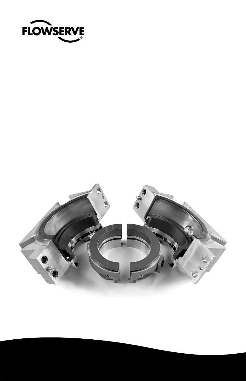
Supplementary PSS II and III
For Goulds 3410 Pumps
Installation
Instructions
Experience In Motion
Page 2

Installation of a PSS II and III on a Goulds 3410 Pump can be simplified
by following the supplemental instructions below. These instructions
should be used in conjunction with the standard PSS II and III Installation
Instructions.
1. After making the appropriate checks and prior to installing the seal,
remove the slingers on the 3410 S and L models (reference Table 1).
If a labyrinth is used on the bearing frame, the seal will not fit. Check
the minimum distance required for PSS II and III installation in Table 1.
Table 1
Pump Model 3410 S 3410 M 3410 L 3410 XL
Sleeve Diameter 1.750" 2.125" 2.750" 3.000"
and Seal Size
Must Slinger Be Yes No Yes No
Removed?
Must Centering Yes Yes Yes No
Devices Be Removed?
1
Bolt Size and Length
Recommended long long long long
Number of Bolts 2 2 2 2
Distance from Stuffing 2.38" 2.69" 2.55" 2.94"
Box to Slinger
Distance from Stuffing 2.54" 2.74" 2.70" 3.09"
Box to Bearing Frame*
Distance from Stuffing - 2.44" 2.18" -
Box to Labyrinth
Minimum Distance 2.40" 2.62" 2.62" 2.62"
Required For
PSS II and III Installation* *
*This is an approximate dimension which varies from pump to pump.
**Assumes that the centering devices are removed.
/2" x 2"
1
/2" x 21/4"1/2" x 21/4"1/2" x 21/4"
2. If there is no drain hole in the bottom of the cradle, drill one.
3. Install the seal drive, rotating face, and stationary face per the
standard instructions. Reference FIS145eng, PSS II Installation
Instructions and FIS175eng, PSS III Installation Instructions.
4. Prior to gland installation, remove the gland centering devices from
seals being installed in the 3410 S, M, and L models (reference Table 1).
© Copyright 2005 Flowserve Corporation
2
Page 3

Bearing Housing Bolts
Figure 1
Figure 2
5. Assemble the gland
halves around the
seal but do not yet bolt
the gland to the pump.
6. Remove the bolts
holding the bearing
housing, Figure 1.
7. Install both gland
bolts. Install the lower
bolt by rotating the
bearing housing 90
degrees for easier
access. See Figure 2.
Tighten the bolts
evenly with the gland
visually centered. Use
a crow foot-wrench to
tighten the lower bolt.
See Figures 3 and 4.
Draw the bolts up
evenly. Finger tight
plus one half turn is
usually adequate.
Figure 3
Figure 4
8. Reinstall the bearing
housing bolts and
complete the PSS II
or III installation per
the standard installation instructions.
3
Page 4

TO REORDER REFER TO
B/M #
.
F.O
USA and Canada
Flowserve Corporation
Flow Solutions
Kalamazoo, Michigan USA
Telephone: 1 269 381 2650
Telefax: 1 269 382 8726
FIS146eng REV 06-05 Printed in USA
To find your local Flowserve representative
and find out more about Flowserve Corporation,
visit www.flowserve.com
Flowserve Corporation has established industry leadership in the design and manufacture of its products. When properly
selected, this Flowserve product is designed to perform its intended function safely during its useful life. However, the
purchaser or user of Flowserve products should be aware that Flowserve products might be used in numerous applications
under a wide variety of industrial service conditions. Although Flowserve can provide general guidelines, it cannot
provide specific data and warnings for all possible applications. The purchaser/user must therefore assume the ultimate
responsibility for the proper sizing and selection, installation, operation, and maintenance of Flowserve products. The
purchaser/user should read and understand the Installation Instructions included with the product, and train its employees
and contractors in the safe use of Flowserve products in connection with the specific application.
While the information and specifications contained in this literature are believed to be accurate, they are supplied for informative
purposes only and should not be considered certified or as a guarantee of satisfactory results by reliance thereon. Nothing
contained herein is to be construed as a warranty or guarantee, express or implied, regarding any matter with respect to this
product. Because Flowserve is continually improving and upgrading its product design, the specifications, dimensions and
information contained herein are subject to change without notice. Should any question arise concerning these provisions, the
purchaser/user should contact Flowserve Corporation at any one of its worldwide operations or offices.
flowserve.com
Europe, Middle East, Africa
Flowserve Corporation
Flow Solutions
Roosendaal, The Netherlands
Telephone: 31 165 581400
Telefax: 31 165 552622
Asia Pacific
Flowserve Corporation
Flow Solutions
Singapore
Telephone: 65 684 65100
Telefax: 65 674 71963
Latin America
Flowserve Corporation
Flow Solutions
Mexico City
Telephone: 52 55 5567 7170
Telefax: 52 55 5567 4224
 Loading...