

Flowserve Limitorque MX-40, Limitorque MX-140, Limitorque MX-150, Limitorque MX-10, Limitorque MX-05 User Instructions
...Page 1

USER INSTRUCTIONS
Swanson Flo | 800-288-7926 | www.swansonflo.com
Limitorque MX
Electronic Actuator
FCD LMENIM2314-00 – 07/08
Maintenance
and Spare Parts
Experience In Motion
Page 2

Swanson Flo | 800-288-7926 | www.swansonflo.com
Page 3

Limitorque MX Maintenance and Spare Parts FCD LMENIM2314-00 – 07/08
Swanson Flo | 800-288-7926 | www.swansonflo.com
Contents
1 Introduction 1
1.1 Premise 1
1.2 Procedure Emphasis 1
1.3 Important Notes and Warning Statements 1
1.4 Reference Documents 2
2 MX Actuator Subassembly 3
2.1 MX Actuator Subassembly Components 4
2.1.1 Product Description 4
2.1.2 Storage 4
2.1.3 Unit Weights 5
2.2 Product Identification 5
2.2.1 Initial Inspection and Recording Suggestions 5
2.3 Maintenance 6
2.3.1 Recommended Maintenance 6
2.3.2 Unit Lubrication 6
2.3.3 O-Ring and Lubrication 8
2.4 Subassembly Removal and Remounting Procedures 8
2.5 How to Order Replacement Subassemblies 9
2.5.1 Replacement Parts 9
2.5.2 Return Procedure 9
3 Remove Actuator from Mounting Adapter 11
3.1 Actuator Removal with Type B1/B4/B4E Base (Torque) 11
3.1.1 Removal (Type B1/B4/B4E Base) 11
3.1.2 Remounting (Type B1/B4/B4E Base) 12
3.2 Actuator Removal with Type A1/A1E Base (Thrust) 14
3.2.1 Removal (Type A1/A1E Base) Actuator Removal Separate from Thrust Base 14
3.2.2 Remounting (Type A1/A1E Base) Actuator Remounting Separate from Thrust Base 15
3.2.3 Removal (Type A1/A1E Base) Actuator and Thrust Base as a Unit 17
3.2.4 Remounting (Type A1/A1E Base) Actuator and Thrust Base as a Unit 18
4 Mechanical Assemblies 19
4.1 Motor 19
4.1.1 Removal 20
4.1.2 Remounting 21
4.1.3 Removal and mounting of MX-140 motor (40 RPM and greater) 22
4.1.4 Remounting 23
4.1.5 Mounting of MX-150 motor 23
4.2 Declutch 25
4.2.1 Removal 27
4.2.2 Remounting 29
4.3 Top-Mounted Handwheel (MX-05, -10, -20, and -40) 32
4.3.1 Removal 33
4.3.2 Remounting 33
4.4 Side-Mounted Handwheel Without Spur Gear Attachment (MX-10, -20, -85, -140, and -150) 35
4.4.1 Side-Mounted Handwheel Without Spur Gear Attachment (MX-85, -140, and -150) 36
4.4.2 Removal of Side-Mounted Handwheel (MX-10, -20, -85, -140, and -150) 37
4.4.3 Removal 37
4.4.4 Remounting 39
i
flowserve.com
Page 4

Limitorque MX Maintenance and Spare Parts FCD LMENIM2314-00 – 07/08
Swanson Flo | 800-288-7926 | www.swansonflo.com
4.5 Side-Mounted Handwheel With Spur Gear Attachment (MX-40, -85, -140, and -150) 40
4.5.1 MX-85, -140, and -150 Handwheel with SGA 41
4.5.2 Removal of Handwheel 42
4.5.3 Removal 42
4.5.4 Remounting 45
4.6 Converting Top-Mounted Handwheel to Side-Mounted Handwheel (MX-10, -20, and -40) 50
4.6.1 Removing Top-Mounted Handwheel 50
4.6.2 Installing Side-Mounted Handwheel 51
4.7 Thrust Base Type A1/A1E 53
4.7.1 Removal 56
4.7.2 Remounting 56
4.8 Torque Base Type B1 57
4.8.1 Removal 58
4.8.2 Remounting 58
4.9 Baseplate Type B4 59
4.9.1 Removal 60
4.9.2 Remounting 62
4.10 Worm Shaft 63
4.10.1 Removal 64
4.10.2 Remounting 65
4.11 Drive Sleeve (MX-05 and -10) 67
4.11.1 Removal 68
4.11.2 Remounting 69
4.12 Drive Sleeve (MX-20, -40, -85, -140, and -150) 70
4.12.1 Removal 71
4.12.2 Remounting 73
4.12.3 MX-85, -140, and -150 Optional Drive Sleeve and Baseplate Removal 74
4.12.4 MX-85, -140, and -150 Optional Drive Sleeve and Baseplate Remounting 76
4.13 Handwheel Adapter (MX-05) 77
4.13.1 Removal 78
4.13.2 Remounting 79
4.14 Handwheel Adapter (MX-10, -20 and -40)/Handwheel Worm Gear (MX-10, -20, -40, -85, -140, and -150) 81
4.14.1 Removal 83
4.14.2 Remounting 84
4.15 Clutch and Clutch Ring Components (MX-20, -40, -85, -140, and -150) 87
4.15.1 Removal 88
4.15.2 Remounting 89
5 Electronic Assemblies 93
5.1 Control Panel (CP) 93
5.2 Control Module 94
5.2.1 Removal 95
5.2.2 Remounting 98
5.2.3 Fuse Replacement 101
5.2.4 Control Module Return Options 102
5.2.5 EPROM Care and Replacement 102
ii
Page 5

Limitorque MX Maintenance and Spare Parts FCD LMENIM2314-00 – 07/08
Swanson Flo | 800-288-7926 | www.swansonflo.com
5.3 Installation and Removal of SMT Controls
(most units supplied after September 2003 and before September 2007) 105
5.3.1 Installation 105
5.3.2 Removal 108
5.3.3 Fuse Replacement 108
5.3.4 Control Module Return Options 108
5.4 Mounting of SMT Controls with 54-point terminal block and four LED configuration
(some units supplied from December 2006 with majority after September 2007) 109
5.4.1 Installation 109
5.4.2 Removal 110
5.5 Mounting of Standard and Optional Controls with 54-point terminal block and four LED configuration 111
5.5.1 Installation 111
5.5.2 Removal 114
5.6 Adding Electronic Options to Your MX Actuator(Most Supplied After September 2007) 114
5.7 Restoring Power to Actuator with New Control Module 115
5.8 Terminal Block (prior to March 2007) 115
5.8.1 Removal 116
5.8.2 Remounting 118
5.9 MX Terminal Block (Supplied With Most Actuators Since March 2007) 120
5.9.1 Terminal Block Shield Installation 120
5.10 Control Module-Contactor Assembly (Not required for most actuators shipped after September 2007.
Please see Section 5.4 for power board installation with contactor.) 121
5.10.1 Removal 122
5.10.2 Remounting 123
5.11 Replacing 19 Amp Reverser on the MX-140 and -150 (Not for most actuators shipped after September 2007) 125
5.12 19 Amp Power Assembly for Units Shipped After September 2007 128
5.13 Encoder (Through hole and surface mount technology, most units prior to September 2007) 129
5.13.1 Removal 130
5.13.2 Remounting 132
5.14 Encoder Drive Cartridge (Most units prior to September 2007) 133
5.14.1 Removal 134
5.14.2 Remounting 135
5.15 Removal and Replacement of MX Encoder (Supplied With Most Actuators Since September 2007) 136
5.15.1 Removal 137
5.15.2 Remounting 137
5.16 Encoder Drive Cartridge (Supplied With Most Actuators Since September 2007) 138
5.16.1 Removal 139
5.16.2 Remounting 140
5.17 Motor Lead Harness (MX-85, -140, and -150) 141
5.17.1 Removal 141
5.17.2 Remounting 142
5.18 Solid State Motor Reverser Upgrade Instructions (Most units prior to September 2007) 143
5.18.1 Disassembly Procedure 144
5.18.2 Assembly Procedure 145
5.19 Mounting of SSMR (Solid State Motor Reverser) in units shipped after February 2008 147
5.20 Complete Conversion to SMT Controls 149
iii
flowserve.com
Page 6

Limitorque MX Maintenance and Spare Parts FCD LMENIM2314-00 – 07/08
Swanson Flo | 800-288-7926 | www.swansonflo.com
6 Spare and Replacement Parts 150
6.1 Guidelines for Recommended Spare Parts 150
6.1.1 Wear Components 150
6.1.2 Bearings, O-rings, and Seals 150
6.1.3 Critical Components 151
6.2 Recommended Spare Parts for MX Actuators 151
6.2.1 Commissioning and Startup 151
6.2.2 Short-Term Duty 151
6.2.3 Long-Term Duty 151
6.2.4 Severe Duty 152
6.3 Other Concerns 152
7 Regulatory Information 154
7.1 Declaration of Conformity 154
Figures
Figure 2.1 – Typical MX Actuator 3
Figure 2.2 – MX Nameplate 5
Figure 2.3 – Oil Fill/Plug Locations (MX-05 through -40) 7
Figure 2.4 – Oil Fill and Drain Locations (MX-85, -140, and -150) 7
Figure 4.1 – Motor (MX-05, -10, -20, and -40) 19
Figure 4.3 – Motor, Support Plate and Adapter (MX-150) 24
Figure 4.4 – Declutch (MX-05 and -10) 25
Figure 4.5 – Declutch (MX-20 and -40) 26
Figure 4.6 – Declutch (MX-85, -140, and -150) 27
Figure 4.7 – Top-Mounted Handwheel (MX-05, -10, -20, and -40) 32
Figure 4.8 – Side-Mounted Handwheel (MX-10 and -20) 35
Figure 4.9 – Side-Mounted Handwheel (MX-85, -140, and -150) 36
Figure 4.10 – Side-Mounted Handwheel with SGA (MX-40) 40
Figure 4.11 – Side-Mounted Handwheel With SGA (MX-85, -140, and -150) 41
Figure 4.12 – Type A1 Thrust Base (MX-05, -10, -20, and -40) 53
Figure 4.13 – Type A1 Thrust Base (MX-85) - F16 Flange 54
Figure 4.14 – Type A1 Thrust Base (MX-85, -140, and -150) - F25 Flange 55
Figure 4.15 – Type B1 Torque Base (MX-05, -10, -20, and -40) 57
Figure 4.16 – Type B4 Baseplate (MX-05, -10, -20, and -40) 59
Figure 4.17 – Type B4 Baseplate (MX-85, -140, and -150) 60
Figure 4.18 – Worm Shaft (MX-05, -10, -20, and -40) 63
Figure 4.19 – Drive Sleeve (MX-05 and -10) 67
Figure 4.20 – MX-20 and -40 Drive Sleeve 70
Figure 4.21 – MX-85, -140, and -150 10:1 and 13:1 ratios 71
Figure 4.22 – Handwheel Adapter (MX-05) 77
iv
Figure 4.23 – Handwheel (MX-05) 77
Figure 4.24 – Handwheel Adapter Assembly 81
Figure 4.25 – Handwheel Worm Gear Assembly 82
Figure 4.26 – MX-20 and -40 Clutch and Ring Components 87
Figure 4.27 – MX-85, -140, and -150 Clutch and Ring Components 87
Page 7

Limitorque MX Maintenance and Spare Parts FCD LMENIM2314-00 – 07/08
Swanson Flo | 800-288-7926 | www.swansonflo.com
Figure 4.28 – MX-85, -140, and -150 Clutch Ring 90
Figure 5.1 – Control Panel 93
Figure 5.2 – Control Module 94
Figure 5.3 – Location of Fuses and Voltage Jumper 101
Figure 5.4 – LCS Board 102
Figure 5.5 – Main CPU Board 102
Figure 5.6 – Power Board 103
Figure 5.7 – DDC Board 103
Figure 5.8 – Location of Fuses and Voltage Jumper 108
Figure 5.9 – SMT Controls with four LEDs 109
Figure 5.10 – Option Board Assembly 113
Figure 5.11 – Restoring Power to Actuator with New Control Module 115
Figure 5.12 – Terminal Block 116
Figure 5.13 – Terminal Block 120
Figure 5.14 – Terminal Block Shield 120
Figure 5.15 – Control Module - Contactor Assembly and Wiring Diagrams 121
Figure 5.15 – (continued) 122
Figure 5.16 – Encoder 130
Figure 5.17 – Encoder Drive Cartridge 133
Figure 5.18 – Encoder 136
Figure 5.19 – Encoder Drive Cartridge 138
Figure 5.20 – Motor Lead Assembly 141
Figure 5.21 – Cutaway View of SSMR Controls Area 143
Figure 5.22 – Disassembly Procedure 144
Figure 5.23 – Solid State Reverser and Fuse Block Assembly Installation 145
Figure 5.24 – Control module reinstallation 146
Figure 5.25 – SSMR (Solid State Motor Reverser) 148
Tables
Table 2.1 – MX Actuator Subassembly Components 4
Table 2.2 – Unit weights 5
Table 2.3 – MX-05 and -10 Oil Capacities when using Oil Fill/Plug Ports 8
Table 4.1 – Motor Parts List 19
Table 4.2 – Motor Parts List 22
Figure 4.2 – Motor and Adapter (MX-140) 22
Table 4.3 – Motor Parts List 23
Table 4.4 – Declutch Parts List (MX-05 and -10) 25
Table 4.5 – Declutch Parts List (MX-20 and -40) 26
Table 4.6 – Declutch Parts List (MX-85, -140, and -150) 27
Table 4.7 – Top-Mounted Handwheel Parts List (MX-05, -10, -20, and -40) 32
Table 4.8 – Side-Mounted Handwheel Parts List (MX-10 and -20) 35
Table 4.9 – Side-Mounted Handwheel without Spur Gear Attachment Parts List (MX-85, -140, and -150) 36
Table 4.10 – Side-Mounted Handwheel Parts List (MX-40) 40
Table 4.11 – Side-Mounted Handwheel Parts List (MX-85, -140, and -150) 41
Table 4.12 – Type A1 Thrust Base Parts List (MX-05, 10, -20, and -40) 53
v
flowserve.com
Page 8

Limitorque MX Maintenance and Spare Parts FCD LMENIM2314-00 – 07/08
Swanson Flo | 800-288-7926 | www.swansonflo.com
Table 4.13 – Type A1 Thrust Base Parts List (MX-85) 54
Table 4.14 – Type A1 Thrust Base Parts List (MX-85, -140, and -150) - F25 Flange 55
Table 4.15 – Type B1 Torque Base Parts List (MX-05, -10, -20, and -40) 57
Table 4.16 – Type B4 Baseplate Parts List 59
Table 4.17 – Worm Shaft Parts List 63
Table 4.18 – Drive Sleeve Parts List (MX-05 and -10) 67
Table 4.19 – Drive Sleeve Parts List (MX-20, -40, -85, -140, and -150) 70
Table 4.20 – Handwheel Adapter Parts List (MX-05) 77
Table 4.21 – Handwheel Adapter Assembly Parts List 81
Table 4.22 – Handwheel Worm Gear Assembly Parts List 82
Table 4.23 – Clutch and Clutch Ring Components Parts List 87
Table 4.24 – Clutch Ring Assembly Parts List 90
Table 5.1 – Control Panel Parts List 93
Table 5.2 – Control Module Parts List 94
Table 5.3 - Voltage Jumper Positions 109
Table 5.4 - Control Board Connectors 112
Table 5.5 - Screw Part Numbers 113
Table 5.5 – Terminal Block Parts List 115
Table 5.7 – Terminal Block Parts List 120
Table 5.8 – Control Module-Contactor Assembly Parts List 121
Table 5.9 – 19 Amp Power Assembly 128
Table 5.10 – Encoder Parts List 129
Table 5.11 – Encoder Drive Sleeve Speed (RPM) 130
Table 5.12 – Encoder Drive Cartridge Parts List 133
Table 5.13 – Encoder Drive Cartridge Drive Sleeve Speed 133
Table 5.14 – Encoder Parts List 136
Table 5.15 – Encoder Drive Sleeve Speed (RPM) 136
Table 5.16 – Encoder Drive Cartridge Parts List 138
Table 5.17 – SSMR Upgrade Kit Parts List 143
Table 5.18 – SSMR Motor Fuse Table 145
Table 5.19 - SSMR Parts List 147
vi
Page 9

1
Swanson Flo | 800-288-7926 | www.swansonflo.com
Limitorque MX Maintenance and Spare Parts FCD LMENIM2314-00 – 07/08
Introduction
1.1 Premise
The Flowserve Limitorque MX actuator components are separated into subassembly groupings. This
manual covers the removal and remounting procedures for each subassembly group. Use these instructions when disassembly is required for service, maintenance, or parts replacement.
1.2 Procedure Emphasis
Please refer to the following methods used to emphasize text throughout this manual. Safety warnings,
cautions, and notes present material that is important to user safety. Be sure to read any safety notices
you see, as they could prevent equipment damage, personal injury, or even death to you or a co-worker.
Safety notices are presented in this manual in three forms:
WARNING: Refers to personal safety. Alerts the user to potential danger. Failure to follow
c
warning notices could result in personal injury or death.
CAUTION: Directs the user’s attention to general precautions that, if not followed, could result in
a
personal injury and/or equipment damage.
NOTE: Highlights information critical to the user’s understanding of the procedure.
Bold text stresses attention to the details of the procedure.
1.3 Important Notes and Warning Statements
Please read this Maintenance and Spare Parts Manual carefully and completely before attempting to
store or perform maintenance on your MX valve actuator. Further installation, setup, and operation
instructions are available in the Installation and Operation manual (LMENIM2306) located in the actuator
terminal compartment at shipment.
1
flowserve.com
Page 10

Limitorque MX Maintenance and Spare Parts FCD LMENIM2314-00 – 07/08
Swanson Flo | 800-288-7926 | www.swansonflo.com
WARNING: Be aware of electrical hazards within the actuator and high-pressure hazards of
c
the attached valve or other actuated device when installing or performing maintenance on
your MX actuator. Failure to observe these precautions could result in serious bodily injury,
damage to the equipment, or operational difficulty.
WARNING: Do not manually operate actuator with devices other than installed handwheel
c
and declutch lever. Using additive force devices (cheater bars, wheel wrenches, pipe
wrenches, or other devices of this nature) on the actuator handwheel or declutch lever may
cause serious personal injury and/or damage to the actuator or valve.
1.4 Reference Documents
• Protection, Control and Monitoring features of MX Electric Actuators (Bulletin LMENTB2300)
• MX Control, Performance and Value in Multi-turn Electric Valve Actuators (Bulletin LMENBR2302)
• MX Installation Manual (Bulletin LMENIM2306)
The latest revisions to these documents are available on-line from Flowserve Limitorque’s website,
www.flowserve.com or at www.limitorque.com
2
Page 11

2
1
3
4
14
9
10
13
8
7
6
5
2
11
Swanson Flo | 800-288-7926 | www.swansonflo.com
Limitorque MX Maintenance and Spare Parts FCD LMENIM2314-00 – 07/08
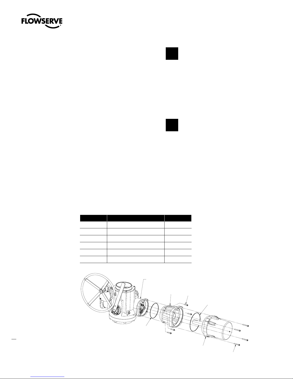
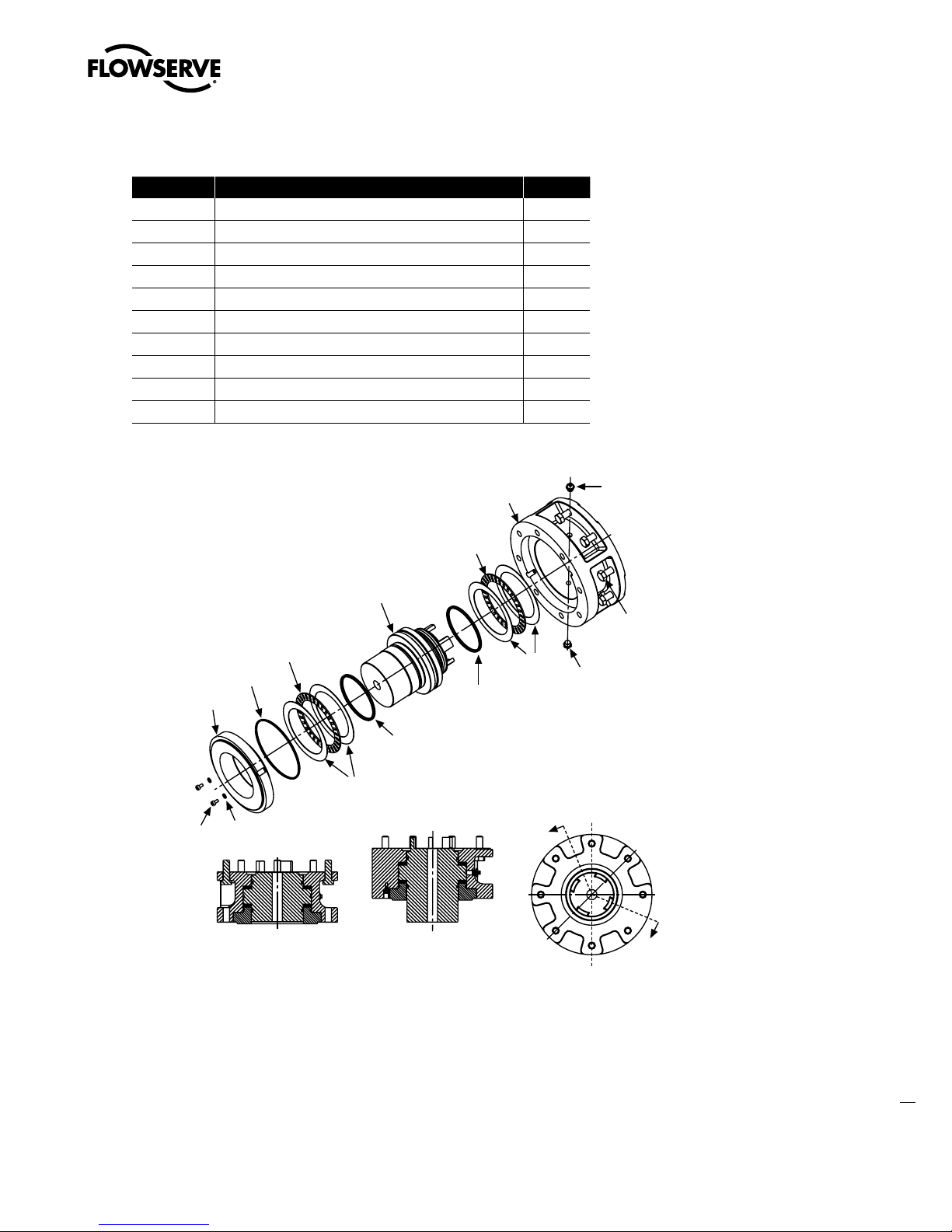
MX Actuator Subassembly
Figure 2.1 – Typical MX Actuator
NOTE: MX-05 with B4 base shown
3
flowserve.com
Page 12

Limitorque MX Maintenance and Spare Parts FCD LMENIM2314-00 – 07/08
Swanson Flo | 800-288-7926 | www.swansonflo.com
2.1 MX Actuator Subassembly Components
Table 2.1 – MX Actuator Subassembly Components
No. Description
1
Top-mounted handwheel
2
Drive sleeve
3
Worm shaft
4
Motor
5
Declutch lever
6
Encoder
7
Control panel (CP)
8
Control module
9
Optional bases
Thrust base type
• A1 = Standard thrust base
• A1E = Extended-reach thrust base
10
Baseplate-type B4 with stem nut options type:
• B4 = stem nut with variable bore and key
• B4E = extended-reach stem nut with variable bore and key
• BL = splined stem nut (SAE or Involute)
11
Handwheel adapter/handwheel worm gear
12
Side-mounted handwheel (not shown, but available for the MX-10, -20,-85, -140, and -150)
13
Encoder drive cartridge
14
Terminal block
2.1.1 Product Description
Your MX actuator controls the opening and closing travel of valves and other actuated devices. OPEN
and CLOSED limits are protected by an absolute encoder that provides optical sensing of valve position
and measures valve position in both motor and handwheel operation. No battery or backup power
supply is required. Output torque is derived from motor speed, temperature, and voltage. If the preset
torque is exceeded, the motor shuts off. As a result of this reliable and advanced protection technology,
all valve and other actuated devices are protected from potential damage from overload, improper
seating, and foreign obstructions.
A range of control and network options is available and can be easily added to the control capabilities
already available on a standard actuator. Contact your local Limitorque distributor or Limitorque sales
office for further information.
2.1.2 Storage
Storage Recommendations
Your MX actuator is double-sealed and weatherproof as shipped, providing all compartment covers and
cable entry plugs are left intact. Actuators should be stored in a clean, dry, protected warehouse until
4
ready for installation. If actuators must be stored outdoors, they should be stored off the ground, high
enough to prevent being immersed in water or buried in snow.
Page 13
Limitorque MX Maintenance and Spare Parts FCD LMENIM2314-00 – 07/08
Swanson Flo | 800-288-7926 | www.swansonflo.com
If your unit incorporates a rising stem application, it may be shipped with a plastic cap over the drive
sleeve. If so, install a pipe plug or protective stem cover to protect the drive sleeve from possible
corrosion.
Preferred Storage Orientation
Your MX actuator should be stored with the motor and terminal compartment in the horizontal position
to obtain optimum service life.
2.1.3 Unit Weights
Table 2.2 – Unit weights
Unit lb. kg
MX-05 52 24
MX-10 65 29
MX-20 109 49
MX-40 133 60
MX-85 259 117
MX-140 300 136
MX-150 410 186
NOTE: Weights include stem nut and lubricant.
2.2 Product Identification
2.2.1 Initial Inspection and Recording Suggestions
Upon receipt of the actuator, several steps should be initially followed to ensure condition of equipment
and to establish proper record keeping.
1. After removing the actuator from the shipping carton or skid, thoroughly examine it for any physical
damage which may have occurred during shipment. If you note any damage, immediately report the
damage to the transport company and call Limitorque for further assistance.
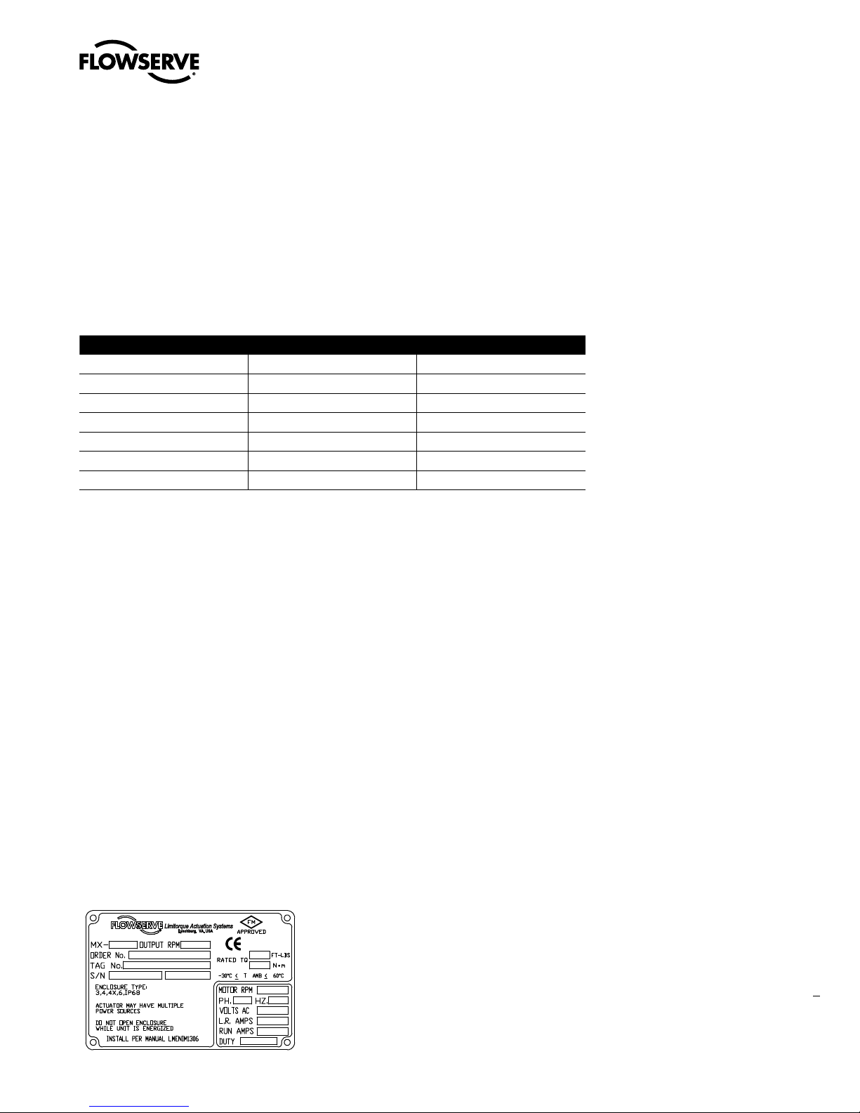
2. A nameplate with important information is attached to each actuator. Record the following information for use when you need to contact Limitorque with any questions about your actuator:
• Unit type/size
• Flowserve Limitorque order number
• Serial number
Figure 2.2 – MX Nameplate
5
flowserve.com
Page 14

Limitorque MX Maintenance and Spare Parts FCD LMENIM2314-00 – 07/08
Swanson Flo | 800-288-7926 | www.swansonflo.com
2.3 Maintenance
2.3.1 Recommended Maintenance
Under normal operating conditions, the MX is a maintenance-free actuator. Therefore, for normal
applications, no formal actuator maintenance is required although visual inspection for oil leakage and
excessive noise is recommended every 1 million drive sleeve turns or every 3000 cycles. When conditions are severe due to frequent operation or high temperatures, inspect the oil level and oil quality more
often. Replace any seals that permit oil leakage or water ingress. When installing pipe plugs, use PTFE
tape or paste to achieve a proper seal.
2.3.2 Unit Lubrication
Check for proper oil level every 1 million drive sleeve turns (reference Installation and Operation Manual
- Diagnostics Section to learn how to view drive sleeve turns data). Change oil every 6000 unit cycles or
if water or other foreign material is found during oil inspection.
Oil Level Inspection and Fill Criteria
(Reference Table 2.3 for oil capacities when mounted in varying positions)
• Actuator viewed in upright position (top-mounted handwheel up)
Oil level should be approximately 1 inch (25.4 mm) below the outer surface of the housing at the oil fill
port.
NOTE: Do not overfill with oil because oil will expand during actuator operation. Actuators are shipped
with an oil volume suitable for any mounting position. When checking the factory-supplied oil level,
excess oil may drain from the highest oil fill port due to the various mounting orientations of each
application.
• Actuator viewed in side-mounted position (terminal compartment up). Oil level should be up to the
bottom of the oil fill plug.
• Actuator viewed in all other positions than described previously should have the oil capacities
maintained. Fill through the highest oil fill port until the oil is at a level that will contact the bottom of
the pipe plug when installed in oil fill port.
6
Page 15

Figure 2.3 – Oil Fill/Plug Locations (MX-05 through -40)
t.9UPQNPVOUFE
IBOEXIFFMPJMDIFDLPJMmMM
t.9TJEFNPVOUFE
IBOEXIFFMPJMDIFDLPJMmMM
t0JMESBJOBMMVOJUT
t.9UPQNPVOUFE
IBOEXIFFMPJMDIFDLPJMmMM
t.9TJEFNPVOUFE
IBOEXIFFMPJMDIFDLPJMmMM
0JM1MVH
0JM1MVH
0JM1MVH
0JM1MVH
0JM1MVH
0JM1MVH
Swanson Flo | 800-288-7926 | www.swansonflo.com
Limitorque MX Maintenance and Spare Parts FCD LMENIM2314-00 – 07/08
Figure 2.4 – Oil Fill and Drain Locations (MX-85, -140, and -150)
Lubrication Data
• Oil Specifications: MX actuators are oil-filled using Mobil SHC-632, which is a synthetic oil suitable for
ambient temperatures of -22°F to 250°F (-30°C to 120°C). For extreme low temperature conditions,
alternative lubricants are available - consult factory for further information.
Table 2.3 – MX-05 and -10 Oil Capacities when using Oil Fill/Plug Ports
Nominal Oil Capacities oz. liters
MX-05
MX-10
MX-20
Top-mounted handwheel with handwheel up 38 1.1
Top-mounted handwheel with terminal compartment up 47 1.4
Side-mounted handwheel with terminal compartment up 43 1.3
10 0.3
16 .05
7
flowserve.com
Page 16

Limitorque MX Maintenance and Spare Parts FCD LMENIM2314-00 – 07/08
Swanson Flo | 800-288-7926 | www.swansonflo.com
MX-40
Top and side-mounted handwheel with handwheel up 40 1.2
Top-mounted handwheel with terminal compartment up 53 1.6
Side-mounted handwheel with terminal compartment up 53 1.6
MX-85, -140, and -150
All Configurations 192 5.7
2.3.3 O-Ring and Lubrication
O-rings and seals should be replaced any time an actuator is disassembled. Lubricate with a substance
that is compatible with Buna N seals.
2.4 Subassembly Removal
and Remounting Procedures
This manual divides each MX actuator subassembly into a Removal and Remounting procedure. Use
the following procedures to remove subassemblies for inspection, repair or replacement. Some subassemblies require prior subassembly removal before allowing the desired subassembly removal. Note
the First Remove instructions at the beginning of each subassembly removal procedure. Remove these
subassemblies first, and then remove the desired subassembly according to the instructions. Once
removed, evaluate subassembly components to determine requirement for a new subassembly. If a new
subassembly is required, see Section 2.5. Once components have been identified and replaced, remount
following the appropriate Remounting procedures.
2.5 How to Order Replacement Subassemblies
2.5.1 Replacement Parts
Replacement parts are sold in modular subassemblies; therefore, when part replacement is required,
order parts at the subassembly levels as shown in this manual. Parts may be ordered from your local
Limitorque representative (see www.flowserve.com) or direct from the factory:
Telephone: 1-434-528-4400
Fax: 1-434-845-9736
8
Page 17

Limitorque MX Maintenance and Spare Parts FCD LMENIM2314-00 – 07/08
Swanson Flo | 800-288-7926 | www.swansonflo.com
Please have the following information, found on the actuator nameplate, available to help us facilitate
your order:
• Unit type/size
• Limitorque order number
• Serial number
2.5.2 Return Procedure
When parts are identified for warranty or other component replacement, a Return Material Authorization
(RMA) must be obtained from Flowserve. Contact factory for a RMA number (see contact information in
section 2.5.1). All returned parts must be accompanied by documentation with the following information
to obtain credit for returned goods:
• Return Material Authorization (RMA)
• Unit type/size
• Flowserve Limitorque order number
• Serial number
Return parts to the address listed below:
Limitorque Actuation Systems
5114 Woodall Road
Lynchburg, VA 24502
9
flowserve.com
Page 18

This page is intentionally blank.
Swanson Flo | 800-288-7926 | www.swansonflo.com
Limitorque MX Maintenance and Spare Parts FCD LMENIM2314-00 – 07/08
10
Page 19

Limitorque MX Maintenance and Spare Parts FCD LMENIM2314-00 – 07/08
Swanson Flo | 800-288-7926 | www.swansonflo.com
Remove Actuator
3
from Mounting Adapter
3.1 Actuator Removal with Type B1/B4/B4E Base (Torque)
3.1.1 Removal (Type B1/B4/B4E Base)
STEP 1
WARNING: Hazardous Voltage! Turn off all power sources to actuator before
c
removing actuator from mounting plate. Power sources may include main power or
control power. If necessary, disconnect incoming power leads L1, L2, L3, and control
wiring from the terminal block.
Remove the bolts that secure the actuator
to the mounting adapter. If type B1 or B4E
base is used in addition to the standard type
B4 or B4E baseplate, you may leave the B1
base attached to the mounting adapter and
remove the actuator only. Or if required, you
may remove the bolts that mount type B1 base
to mounting adapter. This will allow actuator
removal along with optional B1 base.
1
11
flowserve.com
Page 20

Limitorque MX Maintenance and Spare Parts FCD LMENIM2314-00 – 07/08
Swanson Flo | 800-288-7926 | www.swansonflo.com
STEP 2
WARNING: Potential high-pressure vessel! Before disassembling your actuator,
c
ensure that the valve or other actuated device is isolated and is not under pressure.
Lift actuator from mounting adapter.
2
3.1.2 Remounting (Type B1/B4/B4E Base)
STEP 3
Ensure stem nut (#1-22) is secured inside
actuator drive sleeve with retaining ring
(#1-23). Lower the actuator onto the mating
component, making sure to align stem nut key
and keyway with mating component.
STEP 4
Ensure that the actuator and mounting adapter
flange mating holes are aligned correctly.
3
1-22
1-23
4
12
Page 21

Limitorque MX Maintenance and Spare Parts FCD LMENIM2314-00 – 07/08
Swanson Flo | 800-288-7926 | www.swansonflo.com
STEP 5
WARNING: Hazardous Voltage! Turn off all power sources before rewiring incoming
c
power leads L1, L2, L3, and control wiring in the terminal block.
Secure the actuator to the mounting adapter
with mounting bolts.
STEP 6
5
Reconnect incoming power leads L1, L2, L3, and control wiring to the terminal block. Restore
power source when ready for operation.
13
flowserve.com
Page 22

Limitorque MX Maintenance and Spare Parts FCD LMENIM2314-00 – 07/08
Swanson Flo | 800-288-7926 | www.swansonflo.com
3.2 Actuator Removal with Type A1/A1E
Base (Thrust)
NOTE: Two procedure options are available for removing the actuator and thrust base:
1. Remove actuator from thrust base, leaving thrust base mounted to mounting flange or removing
thrust base separately.
2. Remove actuator and thrust base as a unit from mounting flange.
3.2.1 Removal (Type A1/A1E Base)
Actuator Removal Separate from Thrust Base
STEP 1
WARNING: Hazardous Voltage! Turn off all power sources to actuator before
c
removing actuator from mounting plate. Power sources may include main power or
control power. If necessary, disconnect incoming power leads L1, L2, L3, and control
wiring from the terminal block.
Remove the bolts (#10-10) that secure the
actuator to the thrust base assembly (#10).
STEP 2
WARNING: Potential high-pressure vessel! Before disassembling your actuator,
c
ensure that the valve or other actuated device is isolated and is not under pressure.
Lift actuator from thrust base assembly (#10).
1
10-10
10
2
14
10
Page 23

Limitorque MX Maintenance and Spare Parts FCD LMENIM2314-00 – 07/08
Swanson Flo | 800-288-7926 | www.swansonflo.com
STEP 3
WARNING: Potential for actuated device to change position! The thrust base will
c
maintain position only if non-backdriving thread lead is used. Ensure proper thread
lead is used in your application before allowing thrust base to be used for maintaining position when actuator is removed.
Thrust base removal (if required)
The valve position will be maintained if a
locking thread lead is used on the valve stem.
If thrust base removal is required, use the
following removal procedure.
Remove the bolts that secure the thrust base
to the mounting adapter.
3
STEP 4
4
Rotate the thrust base (#10) until it feeds off
the threaded stem.
3.2.2 Remounting (Type A1/A1E Base)
Actuator Remounting Separate from Thrust Base
STEP 5
5
Thrust base remounting (if required)
Ensure the thrust base stem nut has the two
lugs positioned upward to engage with the
drive sleeve slots when actuator is reinstalled
onto thrust base. Thread thrust base back
onto mounting adapter.
10
15
flowserve.com
Page 24

Limitorque MX Maintenance and Spare Parts FCD LMENIM2314-00 – 07/08
Swanson Flo | 800-288-7926 | www.swansonflo.com
STEP 6
Secure thrust base to mounting adapter with
mounting bolts.
STEP 7
Actuator remounting
Lower the actuator onto the thrust base,
making sure thrust nut lugs align and properly
engage with drive sleeve slots.
6
7
STEP 8
8
Install bolts (#10-10) to secure the actuator to
the thrust base assembly (#10).
STEP 9
WARNING: Hazardous Voltage! Turn off all power sources before rewiring incoming
c
power leads L1, L2, L3, and control wiring in the terminal block.
Reconnect incoming power leads L1, L2, L3, and control wiring to the terminal block. Restore
power source when ready for operation.
16
Page 25

Limitorque MX Maintenance and Spare Parts FCD LMENIM2314-00 – 07/08
Swanson Flo | 800-288-7926 | www.swansonflo.com
3.2.3 Removal (Type A1/A1E Base)
Actuator and Thrust Base as a Unit
STEP 1
WARNING: Hazardous Voltage! Turn off all power sources to actuator before
c
removing actuator from mounting plate. Power sources may include main power or
control power. If necessary, disconnect incoming power leads L1, L2, L3, and control
wiring from the terminal block.
Actuator and thrust base removal
Remove the bolts that secure the actuator and
thrust base (#10) to the mounting adapter.
1
STEP 2
WARNING: Potential high-pressure vessel! Before disassembling your actuator,
c
ensure that the valve or other actuated device is isolated and is not under pressure.
Declutch the actuator to manual mode.
2
STEP 3
3
Rotate the handwheel until the actuator lifts
off the threaded stem.
17
flowserve.com
Page 26

Limitorque MX Maintenance and Spare Parts FCD LMENIM2314-00 – 07/08
Swanson Flo | 800-288-7926 | www.swansonflo.com
3.2.4 Remounting (Type A1/A1E Base)
Actuator and Thrust Base as a Unit
STEP 4
4
Actuator and thrust base remounting
Declutch the actuator to manual mode. Lift
actuator up to the threaded stem and carefully
align threads with thrust base threaded stem
nut.
STEP 5
5
Rotate the handwheel to lower the actuator
along the threaded stem and onto the
mounting adapter plate.
18
STEP 6
6
Install the mounting bolts to secure the
actuator and thrust base (#10) to the
mounting adapter.
STEP 7
WARNING: Hazardous Voltage! Turn off all power sources before rewiring incoming
c
power leads L1, L2, L3, and control wiring in the terminal block.
Reconnect incoming power leads L1, L2, L3, and control wiring to the terminal block. Restore
power source when ready for operation.
Page 27

4
A
A
4- 1
4- 2
4- 3
4- 4
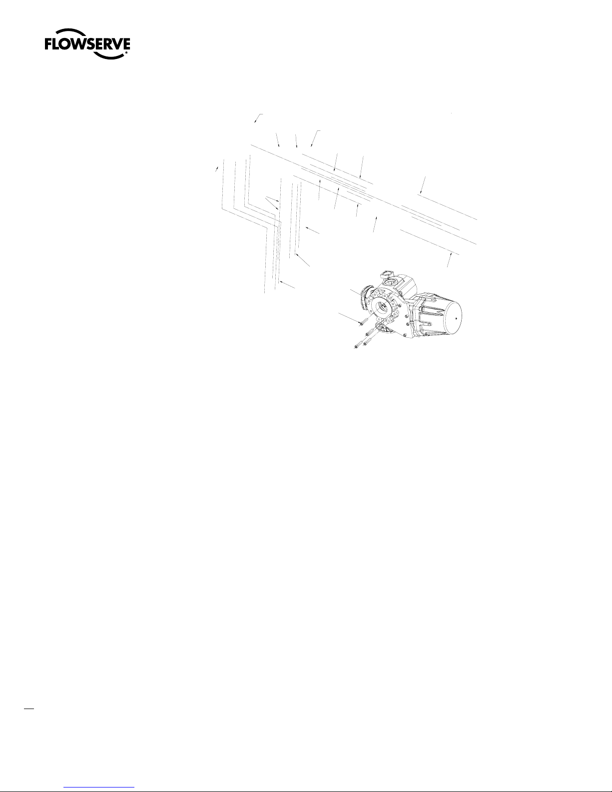
Motor
leads
4- 8
4- 9
A ssembly must have
rotation of rotor as shown.
Phase connections are:
T1-Phase 'A '
T2-Phase 'B '
T3-Phase 'C '
View A-A
Swanson Flo | 800-288-7926 | www.swansonflo.com
Limitorque MX Maintenance and Spare Parts FCD LMENIM2314-00 – 07/08
Mechanical Assemblies
4.1 Motor
NOTE: Proper motor testing is required when replacing motor. Consult your Limitorque representative
or the Limitorque factory to replace with correct motor.
Table 4.1 – Motor Parts List
Part Number Description Qty.
4-1 Motor cover 1
4-2 Stator 1
4-3 Rotor assembly 1
4-4 Bearing 1
4-8 Bearing preload spring 1
4-9 Setscrew 1
Figure 4.1 – Motor (MX-05, -10, -20, and -40)
flowserve.com
19
Page 28

Limitorque MX Maintenance and Spare Parts FCD LMENIM2314-00 – 07/08
Swanson Flo | 800-288-7926 | www.swansonflo.com
4.1.1 Removal
STEP 1
WARNING: Hazardous Voltage! Turn off all power sources to actuator before removing
c
motor assembly. Power sources may include main power or control power.
Using an M6 hex key, remove the four M8
screws (#1-14) that mount the motor assembly
to the MX-05 through MX-40 actuator.
MX-85 requires an M8 hex key and uses an
M10 screw.
1
1-14
STEP 2
CAUTION: The rotor is not connected to the motor housing; when removing the motor,
a
ensure the rotor is carefully removed and not dropped from the motor housing.
Withdraw the complete motor (subassembly
#4), including the rotor (#4-3), until the wiring
harness is accessible. Note the O-ring (#1-15)
on the spigot/pilot of the motor assembly;
replace at remounting.
STEP 3
2
1-15
3
Disconnect the motor power plug from the
motor power socket connector.
4-3
20
Page 29

Limitorque MX Maintenance and Spare Parts FCD LMENIM2314-00 – 07/08
Swanson Flo | 800-288-7926 | www.swansonflo.com
4.1.2 Remounting
STEP 4
WARNING: Hazardous Voltage! Turn off all power sources to actuator before removing
c
motor assembly. Power sources may include main power or control power.
Lightly lubricate the O-ring (#1-15) that
is installed around the motor spigot/pilot
(subassembly #4).
4
1-15
STEP 5
Hold the motor assembly (housing/stator/rotor)
close to the actuator housing and reconnect the
motor power plug to the motor power socket
connector.
STEP 6
Coil the spiral-wrapped motor power wiring
inside the motor cavity and around the motor
bearing housing to ensure that it does not
come into contact with the rotor shaft.
MX-05 through -40 motor wiring will wrap
around about 360°. MX-85/140/150 motor
wiring will wrap around about 180°.
5
6
Motor Power
Socket
Connector
Motor Power
Plug
21
flowserve.com
Page 30
Limitorque MX Maintenance and Spare Parts FCD LMENIM2314-00 – 07/08
MAIN UNIT ASSEMBLY
4-8
1-14
4-10
1-15
4-7
4-9
Swanson Flo | 800-288-7926 | www.swansonflo.com
STEP 7
Push the rotor shaft onto the protruding
worm shaft, aligning the rotor shaft slots with
the worm shaft pin. Slide the motor housing
spigot/pilot into the actuator housing.
STEP 8
Fit the four screws (#1-14) into the motor
subassembly mounting holes and tighten.
7
8
1-14
4.1.3 Removal and mounting of MX-140 motor
(40 RPM and greater)
Table 4.2 – Motor Parts List
Part Number Description Qty.
1-14 Socket head cap screw 4
1-15 O-ring 1
4-7 Motor 1
4-8 Adapter, motor 1
4-9 Socket head cap screw 4
4-10 O-ring 1
Figure 4.2 – Motor and Adapter (MX-140)
22
Page 31

Limitorque MX Maintenance and Spare Parts FCD LMENIM2314-00 – 07/08
Swanson Flo | 800-288-7926 | www.swansonflo.com
STEP 1
Remove the four (4) socket head cap screws (#4-9) from the motor. Exercise caution as the motor is
heavy and the motor leads may be compromised during disassembly.
STEP 2
Remove the motor leads plug from the motor contactor seal assembly.
STEP 3
Remove the four (4) socket head cap screws (#1-15) from the motor adapter. Ensure the motor leads
have been previously disconnected.
4.1.4 Remounting
Follow steps in Section 4.1.3 in reverse order. Ensure O-rings were not damaged in disassembly. If
necessary, replace.
4.1.5 Mounting of MX-150 motor
The assembly of the MX-150 motor is a two-phase process. Phase 1 includes the mounting of the
motor support plate (#4-17), motor adapter (#4-8), and selection of a quantity of shims required to
offset any gap between the motor support plate and the motor support. Phase two includes removal
of the motor support plate, reinstallation with the shims in place and final tightening of all mounting
screws.
Table 4.3 – Motor Parts List
Part Number Description Qty.
1-15 O-ring 1
4-7 Motor 1
4-8 Motor adapter 1
4-9 Socket head cap screws 4
4-10 O-ring 1
4-11 Sheilded ball bearing 1
4-13 Plate, wiring sheild 1
4-14 Socket head cap screws 3
4-15 Socket head cap screws 4
4-16 Pipe plug 6
4-17 Plate, motor support 1
4-18 Shims AS REQ’D
4-19 Socket head cap screws 4
4-20 Socket head cap screws 4
23
flowserve.com
Page 32
Limitorque MX Maintenance and Spare Parts FCD LMENIM2314-00 – 07/08
UNIT HOUSING
1-15
4-8
4-13
4-15
4-7
4-9
4-16
4-10
4-14
4-11
4-18
4-17
4-19
4-20
4-20
UNIT BASEPLATE
UNIT BASEPLATE
MOUNT ADAPTER (PC-4-8) TO UNIT HOUSING
BEFORE MOUNTING MOTOR (PC-4-7)
Swanson Flo | 800-288-7926 | www.swansonflo.com
Figure 4.3 – Motor, Support Plate and Adapter (MX-150)
STEP 1
Install support plate (4-17) to unit base plate using socket head cap screws (#4-20).
STEP 2
Place the lead seal connector through the slot in the adapter (#4-8). Install the adapter loosely to unit
housing using screws (#4-15). Rotate adapter until gap is uniform with plate (#4-17). Tighten screws
(#4-15).
STEP 3
Measure gap and select the shim (#4-18) total thickness to be at least the gap plus up to .1mm (.004
inch). Shims are .1mm (.004 inch) each.
STEP 4
Remove plate (#4-17), install shims (#4-18), reinstall plate to base of unit, tighten screws (#4-20). Then
install and tighten screws (#4-19) with shims in place.
NOTES:
1. Pipe plugs (#4-16) must be installed with tape or pipe sealant over the four (4) mounting screws
(#4-15) and the two (2) jacking tap holes.
2. When mounting motor (#4-7) leads must be placed behind plate (#4-13).
24
Page 33
Limitorque MX Maintenance and Spare Parts FCD LMENIM2314-00 – 07/08
Swanson Flo | 800-288-7926 | www.swansonflo.com
3. Take care not to damage either the O.D. on adapter to I.D on housing and the O.D. on motor to I.D. on
adapter to protect flame path for hazardous certifications.
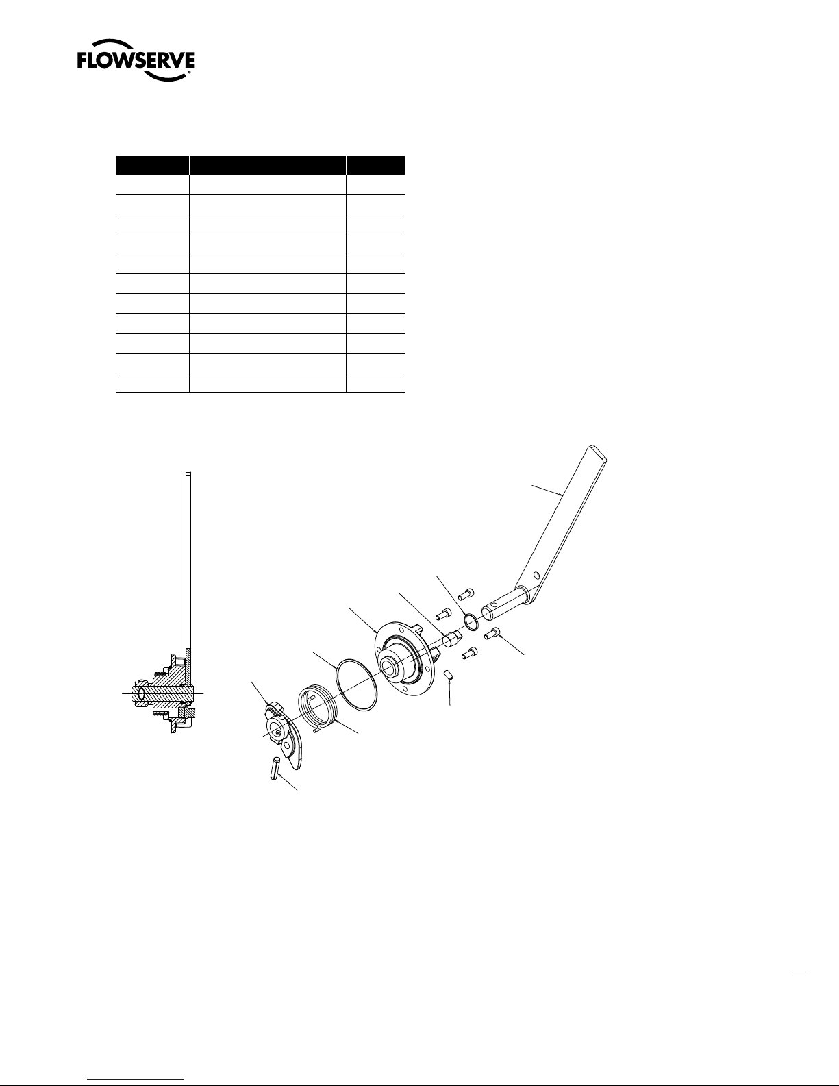
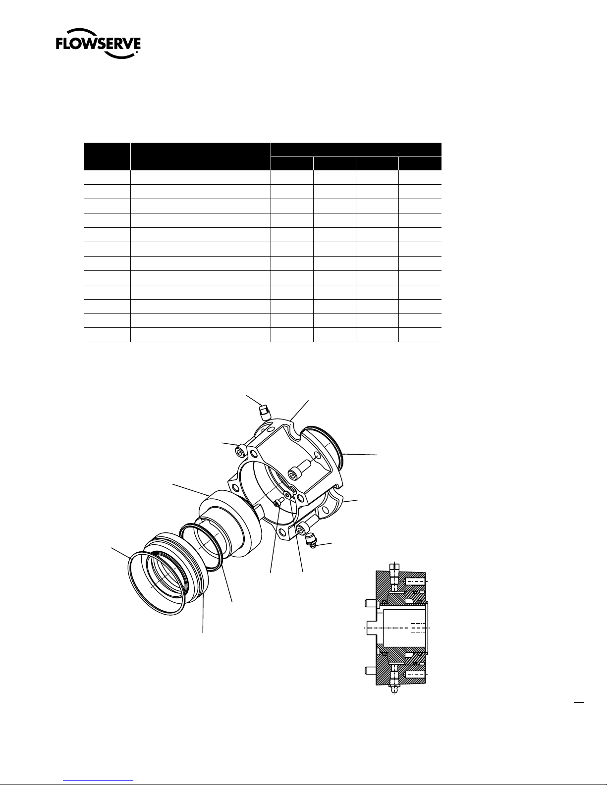
4.2 Declutch
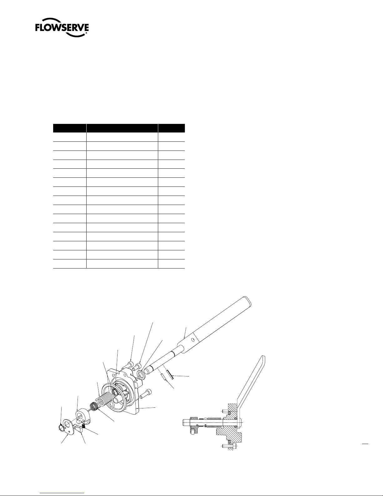
Table 4.4 – Declutch Parts List (MX-05 and -10)
Part Number Description Qty.
5-1 Declutch cover 1
5-2 Declutch shaft 1
5-3 Declutch cam 1
5-4 Declutch spring 1
5-5 Cam spring 1
5-6 Declutch latch 1
5-7 Latch spring 1
5-8 Cam plate 1
5-9 Retaining ring 2
5-10 Socket head cap screw 1
5-11 O-ring 1
5-12 Socket head cap screw 2
5-13 Dowel pin 1
5-14 Roll pin 1
5-15 O-ring 1
Figure 4.4 – Declutch (MX-05 and -10)
25
flowserve.com
Page 34

Limitorque MX Maintenance and Spare Parts FCD LMENIM2314-00 – 07/08
PC. NO. 5-5
Spring,
Declutch
cam
PC. NO. 5- 4
Spring, Declutch shaft
5- 2
5-14
5-13
5-12
5-10
5-11
5- 1
5-15
5- 9
5- 4
5- 5
5- 7
5- 6
5-16
5- 9
5- 3
Swanson Flo | 800-288-7926 | www.swansonflo.com
Table 4.5 – Declutch Parts List (MX-20 and -40)
Part Number Description Qty.
5-1 Declutch cover 1
5-2 Declutch shaft 1
5-3 Declutch cam 1
5-4 Declutch spring 1
5-5 Cam spring 1
5-6 Declutch latch 1
5-7 Latch spring 1
5-8 Cam plate 1
5-9 Retaining ring 2
5-10 Socket head cap screw 1
5-11 O-ring 1
5-12 Socket head cap screw 2
5-13 Dowel pin 1
5-14 Roll pin 1
5-15 O-ring 1
5-16 Dowel pin 1
Figure 4.5 – Declutch (MX-20 and -40)
26
Page 35
Limitorque MX Maintenance and Spare Parts FCD LMENIM2314-00 – 07/08
Swanson Flo | 800-288-7926 | www.swansonflo.com
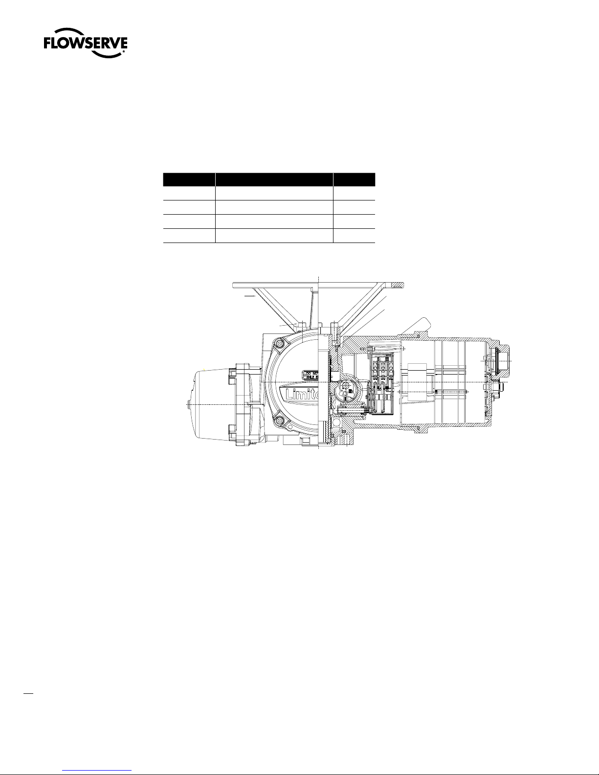
Table 4.6 – Declutch Parts List (MX-85, -140, and -150)
Part Number Description Qty.
5-1 Declutch cover 1
5-2 Declutch shaft 1
5-3 Declutch cam 1
5-4 Declutch spring 1
5-9 Retaining ring 2
5-10 Socket head set screw 1
5-11 O-ring 1
5-12 Socket head set screw 2
5-13 Spiral pin 1
5-15 O-ring 1
5-16 Pipe plug 1
Figure 4.6 – Declutch (MX-85, -140, and -150)
4.2.1 Removal
NOTE: The MX-05, -10, -85, -140, and -150 declutch assembly may be removed and remounted without
other subassembly removal.
NOTE: The MX-20 and -40 declutch assembly may be removed without other subassembly removal, but
remounting requires removing the following subassemblies:
1. Handwheel (Subassembly #13)
2. Handwheel adapter (Subassembly #12)
3. Clutch and clutch ring (Subassembly #16)
27
flowserve.com
Page 36

Limitorque MX Maintenance and Spare Parts FCD LMENIM2314-00 – 07/08
X
Swanson Flo | 800-288-7926 | www.swansonflo.com
STEP 1
WARNING: Potential to operate while dangerous mechanical parts are exposed during
c
subassembly removal. To prevent injury, turn off all power sources to actuator before
removing side-mounted and top-mounted handwheel assembly. Power sources may
include main power or control power.
NOTE: Oil removal is not necessary on MX-05, -10, -85, -140, and -150 if actuator is mounted with
declutch lever up.
Drain oil from actuator using the lowest of three
plugs in your application mounting orientation.
STEP 2
WARNING: Potential to operate while dangerous mechanical parts are exposed during
c
subassembly removal. To prevent injury, turn off all power sources to actuator before
removing declutch assembly. Power sources may include main power or control power.
Using a 5 mm (MX-05 and -10) or 6 mm
(MX-20, -40, -85, -140, and -150) hex key,
remove the two M6 (MX-05 and -10) screws
(#5-12), M8 (MX-20 and -40) or the four M8
(MX-85, -140, and -150) screws that retain the
declutch assembly cover (#5-1) on the actuator
housing.
1
2
Oil Plug Drains
5-12
5-1
28
Page 37

STEP 3
Swanson Flo | 800-288-7926 | www.swansonflo.com
Withdraw the complete declutch assembly,
slightly twisting if necessary, to remove. Note
the O-ring (#5-15) with the declutch assembly
cover (#5-1). Replace at remounting.
Picture 3a is typical MX-05 through -40. Picture
3b is typical MX-85/140/150.
Limitorque MX Maintenance and Spare Parts FCD LMENIM2314-00 – 07/08
3a
5-15
3b
4.2.2 Remounting
STEP 4
(MX-20 and -40 only) Remove the following
subassemblies before remounting the declutch
assembly. (See corresponding referenced
sections for removal information.)
1. Handwheel (subassembly #13). (See
Section 4.3.1.)
2. Handwheel adapter (subassembly #12).
(See Section 4.13.1.)
3. Clutch and clutch ring (subassembly #16).
(See Section 4.15.1.)
Lightly lubricate the O-ring (#5-15) and fit it to
the inner race of the declutch cover (#5-1).
4
5-15
29
flowserve.com
Page 38

Limitorque MX Maintenance and Spare Parts FCD LMENIM2314-00 – 07/08
Swanson Flo | 800-288-7926 | www.swansonflo.com
STEP 5
CAUTION: (MX-20 and -40 only) To create proper mating between the cam latch (#5-6)
a
and the shoulder on the worm gear, ensure cam latch is positioned below the worm gear
shoulder (see Picture 5a).
TIP: (MX-20 and -40 only) - Picture 5a shows
proper alignment between the cam latch (#5-6)
and the shoulder on the worm gear.
TIP: (MX-20 and -40 only) - Picture 5b shows
improper alignment between the cam latch
(#5-6) and the shoulder on the worm gear.
Improper alignment could cause the cam latch
to be broken off by the worm gear lug.
TIP: (MX-85, -140, and -150 only) - Picture 5c
shows proper alignment between the cam and
the clutch ring roller.
Fit the complete declutch assembly into the
actuator housing, slightly twisting if necessary,
to remount into actuator. See picture 5d.
5a
Cam Latch and
Worm Gear
Shoulder Proper
Alignment
5b
Cam latch and
worm gear shoulder
improper alignment
30
5c
5d
Page 39

Limitorque MX Maintenance and Spare Parts FCD LMENIM2314-00 – 07/08
Swanson Flo | 800-288-7926 | www.swansonflo.com
STEP 6 (MX-85, -140, AND -150 ONLY)
Set screw adjustment. Install drive sleeve, baseplate, clutching and handwheel worm gear components. Assure the clutch lugs are fully engaged to the motor worm gear lugs before the adjustment.
With declutch lever resting on cap pad (not the set screw) place declutch cap assembly (1-4) into
housing without mounting screws. Rotate cap assembly clockwise until declutch cam is resisted
by the roller, clutch ring and clutch combination. Holding the declutch lever, rotate the set screw
clockwise through declutch cap, (this will rotate the cap counterclockwise) until the cap mounting
holes are inline with the taps in the housing. Install declutch assembly mounting screws. Then
rotate set screw counterclockwise ¼ turn, plus or minus
STEP 7
Fit the two M6 (MX-05 and -10) screws
(#5-12), M8 (MX-20 and -40) screws to retain
the declutch assembly cover (#5-1) on the
housing. Tighten using a 5 mm (MX-05 and
-10) or 6 mm (MX-20, -40 and -85) hex key.
Picture 7a shows the two screws for the MX-20
and -40. Picture 7b shows the four screws for
the MX-85.
1
⁄8 turn. Adjustment is complete.
7a
See picture 7a for MX-05, -10, -20 and -40. See
picture 7b for MX-85, -140, and -150.
STEP 8 (MX-20 AND -40 ONLY)
Remount the following subassemblies after remounting the declutch assembly.
(See corresponding referenced sections for remounting information.)
1. Handwheel (subassembly #13). (See Section 4.3.2.)
2. Handwheel adapter (subassembly #12). (See Section 4.4.2, 4.4.3, and 4.5.3.)
3. Clutch and clutch ring (subassembly #16). (See Section 4.15.2.)
7b
31
flowserve.com
Page 40
Limitorque MX Maintenance and Spare Parts FCD LMENIM2314-00 – 07/08
1-9 (MX-05 only) Handwheel spacer (1)
1-10 Wave spring (1)
1-8 Handwheel (1)
1-11 Socket head cap screw (4)
Swanson Flo | 800-288-7926 | www.swansonflo.com
4.3 Top-Mounted Handwheel
(MX-05, -10, -20, and -40)
Table 4.7 – Top-Mounted Handwheel Parts List (MX-05, -10,
-20, and -40)
Part Number Description Qty.
1-8 Handwheel 1
1-9 Handwheel Spacer (MX-05 only) 1
1-10 Wave Spring 1
1-11 Socket head cap screw 4
Figure 4.7 – Top-Mounted Handwheel (MX-05, -10, -20, and -40)
32
WARNING: Do not manually operate the actuator with devices other than the installed
c
handwheel and declutch lever. Using force beyond the ratings of the actuator and/or additive
forces such as cheater bars, wheel wrenches, pipe wrenches, or other devices on the actuator
handwheel or declutch lever may cause serious personal injury and/or damage to the actuator
and valve.
Page 41

Limitorque MX Maintenance and Spare Parts FCD LMENIM2314-00 – 07/08
Swanson Flo | 800-288-7926 | www.swansonflo.com
4.3.1 Removal
STEP 1
WARNING: Potential to operate while dangerous mechanical parts are exposed during
c
subassembly removal. To prevent injury, turn off all power sources to actuator before
removing top-mounted handwheel assembly. Power sources may include main power
or control power.
Using a 6 mm (MX-05 and -10) hex key or
8 mm (MX-20 and -40) hex key, remove the
four screws (#1-11) that secure the handwheel
(#1-8) to the handwheel adapter assembly
(#1-1).
1
STEP 2
Lift the handwheel (#1-8) off the handwheel
adapter (#1-1).
4.3.2 Remounting
STEP 3
Install handwheel (#1-8) onto handwheel
adapter assembly (#1-1).
1-8
11-1
2
3
1-1
1-8
33
flowserve.com
Page 42

Limitorque MX Maintenance and Spare Parts FCD LMENIM2314-00 – 07/08
Swanson Flo | 800-288-7926 | www.swansonflo.com
STEP 4
Align the handwheel slots with the mounting
holes. Fit the four screws (#1-11) in handwheel
mounting holes and tighten.
4
34
Page 43

Limitorque MX Maintenance and Spare Parts FCD LMENIM2314-00 – 07/08
Swanson Flo | 800-288-7926 | www.swansonflo.com
4.4 Side-Mounted Handwheel Without Spur Gear
Attachment (MX-10, -20, -85, -140, and -150)
Table 4.8 – Side-Mounted Handwheel Parts List (MX-10 and -20)
Part Number Description Qty.
13-1 Handwheel wormshaft 1
13-2 Handwheel worm cap 1
13-3 Ball bearing 1
13-4 Quad ring 1
13-5 Seal retainer 1
13-6 O-ring 1
13-7 Roll pin 1
13-8 Ball bearing 1
13-9 Socket head cap screw 2 (MX-10), 4 (MX-20)
13-10 Side-Mounted handwheel 1
Figure 4.8 – Side-Mounted Handwheel (MX-10 and -20)
WARNING: Do not manually operate the actuator with devices other than the installed
c
handwheel and declutch lever. Using force beyond the ratings of the actuator and/or additive
forces such as cheater bars, wheel wrenches, pipe wrenches, or other devices on the actuator
handwheel or declutch lever may cause serious personal injury and/or damage to the actuator
and valve.
35
flowserve.com
Page 44

Limitorque MX Maintenance and Spare Parts FCD LMENIM2314-00 – 07/08
4&$5*0/""
Swanson Flo | 800-288-7926 | www.swansonflo.com
4.4.1 Side-Mounted Handwheel Without Spur Gear Attachment
(MX-85, -140, and -150)
Table 4.9 – Side-Mounted Handwheel without Spur Gear
Attachment Parts List (MX-85, -140, and -150)
Part Number Description Qty.
13-1 Handwheel wormshaft 1
13-2 Handwheel worm cap 1
13-3 Ball bearing 1
13-4 Quad ring 1
13-5 Roll pin 1
13-6 O-ring 1
13-7 Key 1
13-8 Needle bearing 1
13-9 Socket head cap screw 4
13-10 Side-Mounted handwheel 1
13-18 Socket head set screw 1
WARNING: Do not manually
c
operate the actuator with
devices other than the installed
handwheel and declutch lever.
Using force beyond the ratings
of the actuator and/or additive
forces such as cheater bars,
wheel wrenches, pipe wrenches,
or other devices on the actuator
handwheel or declutch lever may
cause serious personal injury
and/or damage to the actuator
and valve.
Figure 4.9 – Side-Mounted Handwheel (MX-85, -140, and -150)
36
Page 45

Limitorque MX Maintenance and Spare Parts FCD LMENIM2314-00 – 07/08
Swanson Flo | 800-288-7926 | www.swansonflo.com
4.4.2 Removal of Side-Mounted Handwheel
(MX-10, -20, -85, -140, and -150)
NOTES: The MX-10 and -20 handwheel is
mounted with a roll pin (13-7). If removal of the
handwheel from the worm shaft is necessary,
remove the handwheel and worm shaft
assembly from unit before removing roll pin.
Removing the roll pin before disassembly of
worm shaft will damage the ball bearing (13-3).
The MX-85, -140, and -150 handwheel is
mounted with a key (13-7) and a set screw
(13-18). See pictures a and b.
a
b
4.4.3 Removal
STEP 1
WARNING: Potential to operate while dangerous mechanical parts are exposed during
c
subassembly removal. To prevent injury, turn off all power sources to actuator before
removing side-mounted handwheel assembly. Power sources may include main power
or control power.
Drain oil from actuator using the lowest of three
plugs in your application mounting orientation.
NOTE: Oil removal is not necessary if the
actuator is mounted on valve or other device
with the drive sleeve in a vertical position.
1
Oil Plug Drains
37
flowserve.com
Page 46

Limitorque MX Maintenance and Spare Parts FCD LMENIM2314-00 – 07/08
Swanson Flo | 800-288-7926 | www.swansonflo.com
STEP 2 (MX-10 AND -20)
CAUTION: Be aware of inner bearing (#13-8) when removing the side-mounted hand-
a
wheel. It may stay in the actuator housing or come out with the side-mounted handwheel
assembly. Ensure it is inserted back in actuator housing before remounting side-mounted
handwheel assembly.
TIP: (MX-85, -140, and -150 only) Needle bearing (#13-8) is pressed into housing.
Using a 6 mm hex key, remove the M8 screws
(#13-9) from the handwheel worm shaft cap
(#13-2).
2
13-9
13-2
STEP 3
Rotate the handwheel assembly clockwise
(CW) to withdraw the complete subassembly
(#13) from the actuator housing.
3
38
Page 47

4.4.4 Remounting
Swanson Flo | 800-288-7926 | www.swansonflo.com
STEP 4
Check that bearing (#13-8) is correctly in place
in the actuator housing.
The MX-10 and -20 is a slip fit (4a).
The MX-85, -140, and -150 is a press fit (4b).
Limitorque MX Maintenance and Spare Parts FCD LMENIM2314-00 – 07/08
4a
13-8
4b
STEP 5
Insert the complete subassembly into the
actuator housing, rotating counterclockwise
(CCW) to properly mesh the gearing. Ensure
the end of the worm shaft is seated in the inner
bearing (#13-8).
STEP 6
Position the worm shaft cap (#13-2) back on
the actuator housing. Using a 6 mm hex key, fit
the (#13-9) screws onto the worm shaft cap to
secure side-mounted assembly to the actuator
housing.
5
6
39
flowserve.com
Page 48

Limitorque MX Maintenance and Spare Parts FCD LMENIM2314-00 – 07/08
Swanson Flo | 800-288-7926 | www.swansonflo.com
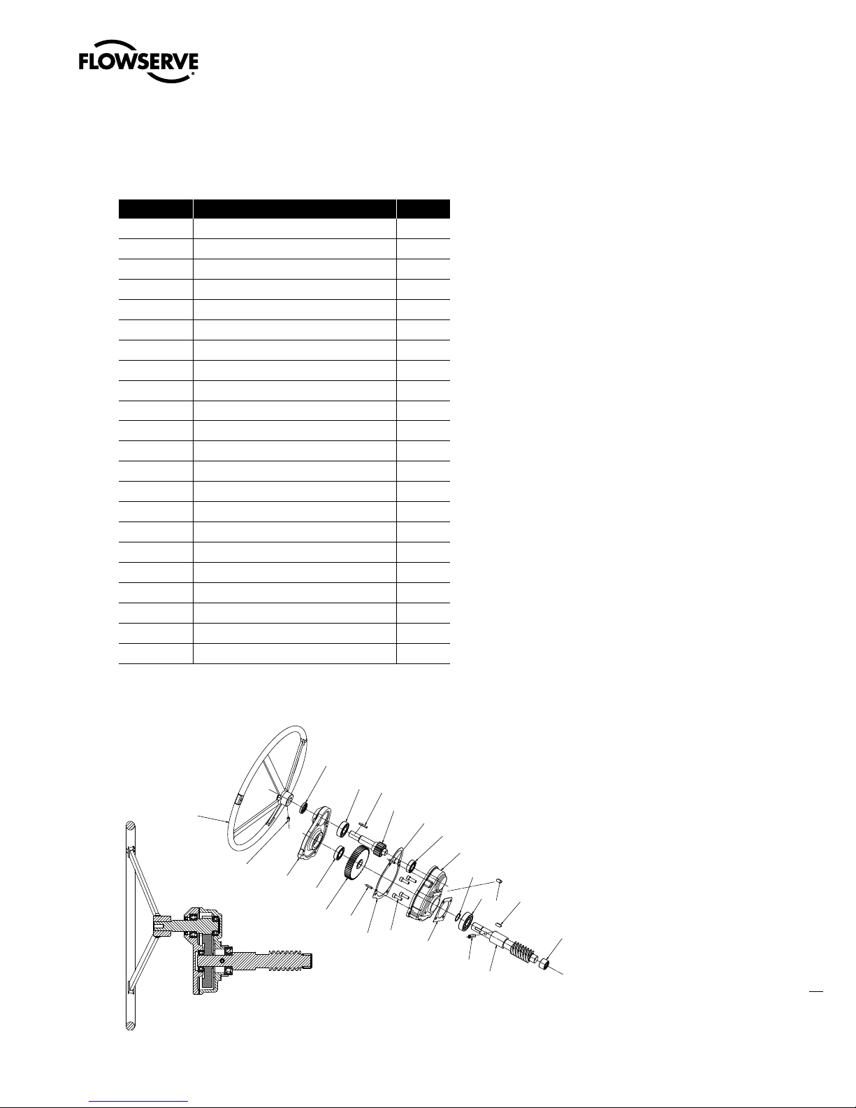
4.5 Side-Mounted Handwheel With Spur Gear
Attachment (MX-40, -85, -140, and -150)
Table 4.10 – Side-Mounted Handwheel Parts List (MX-40)
Part Number Description Qty.
13-1 Handwheel worm shaft 1
13-2 Spur adapter plate 1
13-3 Ball bearing 1
13-6 O-ring 1
13-7 Roll pin 1
13-8 Ball bearing 1
13-9 Socket head cap screw M8x25 4
13-10 Side-Mounted handwheel 1
13-11 Needle bearing 3
13-12 Handwheel input gear 1
13-13 Spur adapter cap 1
13-14 Handwheel input pinion 1
13-15 Quad ring 1
13-16 O-ring spacer 1
13-17 Dowel pin 1
13-18 Roll pin 1
13-19 O-ring 1
13-20 Socket head cap screw M8x20 4
WARNING: Do not manu-
c
ally operate the actuator
with devices other than
the installed handwheel
and declutch lever. Using
force beyond the ratings
of the actuator and/
or additive forces such
as cheater bars, wheel
wrenches, pipe wrenches,
or other devices on the
actuator handwheel or
declutch lever may cause
serious personal injury
and/or damage to the
actuator and valve.
40
Figure 4.10 – Side-Mounted Handwheel with SGA (MX-40)
Page 49
Limitorque MX Maintenance and Spare Parts FCD LMENIM2314-00 – 07/08
13-10
13-18
13-17
13-19
13-9
13-6
13-5
13-1
13-8
13-24
13-24
13-3
13-28
13-2
13-17
13-14
13-7
13-23
13-15
13-11
13-12
13-22
13-13
Swanson Flo | 800-288-7926 | www.swansonflo.com
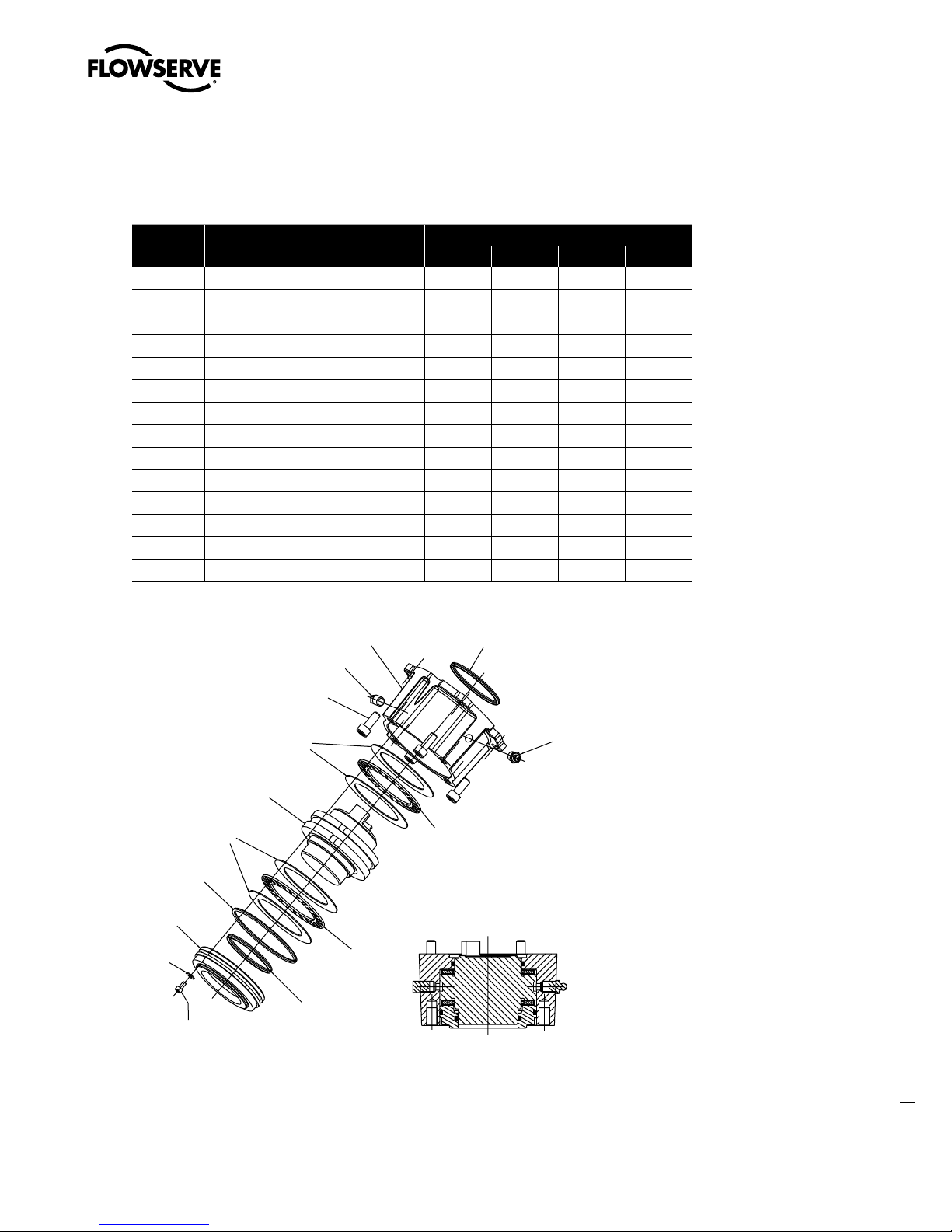
4.5.1 MX-85, -140, and -150 Handwheel with SGA
Table 4.11 – Side-Mounted Handwheel Parts List (MX-85, -140,
and -150)
Part Number Description Qty.
13-1 Handwheel worm shaft 1
13-2 Spur adapter plate 1
13-3 Ball bearing 1
13-5 Spiral pin 1
13-6 Gasket 1
13-7 Key 1
13-8 Needle bearing 1
13-9 Socket head cap screw M8x25 4
13-10 Side-Mounted handwheel 1
13-11 Ball bearing 1
13-12 Handwheel input gear 1
13-13 Spur adapter cap 1
13-14 Handwheel input pinion 1
13-15 Oil seal 1
13-17 Dowel pin 1
13-18 Set screw 1
13-19 Gasket 1
13-20 Socket head cap screw M8x20 4
13-22 Ball bearing 1
13-23 Ball bearing 1
13-24 Key 2
13-28 Retaining ring 1
WARNING: Do not manually
c
operate the actuator w/ devices
other than the installed handwheel and declutch lever. Using
force beyond the ratings of the
actuator and/or additive forces
such as cheater bars, wheel
wrenches, pipe wrenches, or
other devices on the actuator
handwheel or declutch lever
may cause serious personal
injury and/or damage to the
actuator and valve.
Figure 4.11 – Side-Mounted Handwheel With SGA (MX-85, -140, and -150)
41
flowserve.com
Page 50

Limitorque MX Maintenance and Spare Parts FCD LMENIM2314-00 – 07/08
Swanson Flo | 800-288-7926 | www.swansonflo.com
4.5.2 Removal of Handwheel
NOTES: The MX-40 handwheel is mounted with
a roll pin (#13-7). If removal of the handwheel
from the worm shaft is necessary, remove the
handwheel and worm shaft assembly from unit
before removing roll pin. Removing the roll pin
before disassembly of worm shaft will damage
the ball bearing (#13-3).
The MX-85, -140, and -150 handwheel is
mounted with a key (#13-7) and a set screw
(#13-18). See pictures a and b.
a
b
42
STEP 4
Remove the four M6 screws (#13-9) from the worm shaft plate (#13-2).
4.5.3 Removal
STEP 1
WARNING: Potential to operate while dangerous mechanical parts are exposed during
c
subassembly removal. To prevent injury, turn off all power sources to actuator before
removing side-mounted handwheel assembly. Power sources may include main power
or control power.
NOTE: Oil removal is not necessary if the actuator is mounted on valve or other device with the
drive sleeve in a vertical position.
Drain oil from actuator using the lowest of three
plugs in your application orientation.
1
Oil Plug Drains
Page 51

Limitorque MX Maintenance and Spare Parts FCD LMENIM2314-00 – 07/08
Swanson Flo | 800-288-7926 | www.swansonflo.com
STEP 2
CAUTION: Be aware of inner bearing (#13-8) when removing the side-mounted hand-
a
wheel. It may stay in the actuator housing or come out with the side-mounted handwheel
assembly. Ensure it is inserted back in actuator housing before remounting side-mounted
handwheel assembly.
Remove the four screws (#13-20) from the
handwheel spur gear cap (#13-13).
2
13-20
STEP 3
Remove handwheel spur gear cap assembly.
Note when assembly is removed, the spur gear
(#13-12) is loose in spur gear cap. Remove
spur gear.
3a
13-12
MX-40
3b
13-12
MX-85/140/150
43
flowserve.com
Page 52

Limitorque MX Maintenance and Spare Parts FCD LMENIM2314-00 – 07/08
Swanson Flo | 800-288-7926 | www.swansonflo.com
STEP 4
Remove the four M6 screws (#13-9) from the
worm shaft plate (#13-2).
4a
13-9
13-2
MX-40
4b
STEP 5
Removing worm shaft assembly.
MX-40: Remove adapter plate and worm
assembly together (5a).
MX-85/140/150: Remove adapter plate, then
remove worm assembly (5b).
NOTE: When removing the side-mounted
handwheel, the inner bearing (#13-8) should
remain in place in the housing.
Rotate the handwheel assembly clockwise
(CW) to withdraw the complete worm shaft
plate subassembly.
MX-85/140/150
5a
MX-40
5b
44
MX-85/140/150
Page 53

STEP 6
Swanson Flo | 800-288-7926 | www.swansonflo.com
If needed, remove the handwheel worm gear
assembly (#12-1). (See Section 4.14.1 for
removal procedure.)
4.5.4 Remounting
STEP 7
Check that bearing (#13-8) is correctly in place
in the actuator housing.
MX-40 is slip fit in housing (7a).
Limitorque MX Maintenance and Spare Parts FCD LMENIM2314-00 – 07/08
6
Handwheel Worm Gear Adapter (12-1)
7a
MX-85 is press fit in housing (7b).
STEP 8
If previously removed, install handwheel worm
gear assembly (#12-1). (See Section 4.14.2 for
remounting procedure.)
13-8
7b
8
Handwheel Worm Gear Adapter (12-1)
45
flowserve.com
Page 54

Limitorque MX Maintenance and Spare Parts FCD LMENIM2314-00 – 07/08
Swanson Flo | 800-288-7926 | www.swansonflo.com
STEP 9
Ensure O-ring (MX-40) (#13-6) is in place on
worm shaft plate.
MX-40, -85, -140, and -150: Insert worm
shaft assembly into actuator housing. Rotate
assembly in counterclockwise (CCW) direction
to properly mate with handwheel worm gear
assembly (#12-1)(9b).
9a
13-6
9b
13-2
STEP 10A - MX-40
Secure with four M8 screws (#13-9) to secure
the adapter plate (#13-2).
10a
13-9
13-2
46
Page 55

STEP 10A AND B - MX-85, -140, AND -150
Swanson Flo | 800-288-7926 | www.swansonflo.com
Ensure gasket (#13-6) is placed on adapter
(#13-2) and install adapter to housing and
secure with four M8 screws (#13-9).
Limitorque MX Maintenance and Spare Parts FCD LMENIM2314-00 – 07/08
10b
10c
47
flowserve.com
Page 56

Limitorque MX Maintenance and Spare Parts FCD LMENIM2314-00 – 07/08
Swanson Flo | 800-288-7926 | www.swansonflo.com
STEP 11
MX-40 (11a)
Fit gear (#13-12) onto end of worm shaft
(#13-1). Ensure gear slot is fitted into pin
(#13-7).
11a
13-1
13-7
MX-85, -140, and -150 (11b and 11c)
Fit gear (#13-12) onto end of worm shaft.
Ensure both keys (#13-24) are in place in worm
shaft.
13-12
11b
13-24
11c
13-12
48
Page 57

STEP 12A - MX-40
Swanson Flo | 800-288-7926 | www.swansonflo.com
Ensure O-ring (#13-19) is in place on worm
shaft plate (#13-2).
STEP 12B - MX-85, -140, AND -150
Ensure gasket (#13-19) is in place on adapter
(#13-2).
Limitorque MX Maintenance and Spare Parts FCD LMENIM2314-00 – 07/08
12a
13-19
13-2
12b
STEP 13A - MX-40
Check that quad ring (#13-15), spacer (#13-16)
and needle bearing (#13-11) are correctly
placed in plate (#13-2) and cap (#13-13).
Install handwheel spur cap assembly, secure
with screws (#13-20).
STEP 13B - MX-85, -140, AND -150
Check that seal (#13-15), and ball bearings
(#13-11, 13-22, and 13-23) are correctly placed
in adapter (#13-2) and cap (#13-13).
Install handwheel spur cap assembly. Secure
with screws (#13-20). Remount handwheel
(#13-10) if removed with key (#13-7) and set
screw (#13-18).
13a
13b
49
flowserve.com
Page 58

Limitorque MX Maintenance and Spare Parts FCD LMENIM2314-00 – 07/08
Swanson Flo | 800-288-7926 | www.swansonflo.com
4.6 Converting Top-Mounted Handwheel
to Side-Mounted Handwheel
(MX-10, -20, and -40)
4.6.1 Removing Top-Mounted Handwheel
WARNING: Do not manually operate the actuator with devices other than the installed
c
handwheel and declutch lever. Using force beyond the ratings of the actuator and/or additive
forces such as cheater bars, wheel wrenches, pipe wrenches, or other devices on the actuator
handwheel or declutch lever may cause serious personal injury and/or damage to the actuator
and valve.
STEP 1
WARNING: Potential to operate while dangerous mechanical parts are exposed during
c
subassembly removal. To prevent injury, turn off all power sources to actuator before
removing side-mounted and top-mounted handwheel assembly. Power sources may
include main power or control power.
Drain oil from actuator using the lowest of three
plugs in your application mounting orientation.
NOTE: Oil removal is not necessary if actuator
is mounted on valve or other device with the
drive sleeve in a vertical position.
NOTE: MX-10 shown.
1
Oil Plug
Drains
50
Page 59

STEP 2
Swanson Flo | 800-288-7926 | www.swansonflo.com
Remove top-mounted handwheel assembly
(#1) and handwheel adapter assembly (#12-1)
using disassembly instructions detailed in
Sections 4.3.1 and 4.13.1 respectively.
Limitorque MX Maintenance and Spare Parts FCD LMENIM2314-00 – 07/08
2a
2b
12
STEP 3
Using a 6 mm hex key, remove the M8 screws
(#13-9) from the handwheel worm shaft cap
(#13-2).
3
13-9
4.6.2 Installing Side-Mounted Handwheel
STEP 4
Install bearing (#13-8) from side-mounted
handwheel adapter kit into the actuator
housing.
MX-10, -20 and -40: the bearing is a slip fit into
the housing.
MX-85, -140, and -150: the bearing is a press
fit into the housing.
4
13-2
13-8
51
flowserve.com
Page 60

Limitorque MX Maintenance and Spare Parts FCD LMENIM2314-00 – 07/08
Swanson Flo | 800-288-7926 | www.swansonflo.com
STEP 5
Replace the handwheel adapter (#12-5) with
the handwheel worm gear (#12-1) that is
included in the side-mounted handwheel
adapter kit.
STEP 6 (MX-20 AND -40 ONLY)
Place the O-ring (#12-4) around the handwheel
adapter; pressing the O-ring into the slot
between the handwheel worm gear adapter
assembly (#12-1) and the actuator housing
(approximately every 15° to 30° until O-ring
seats into slot).
5
12
6
12-4
STEP 7
Place the retainer plate (#1-32) on the top of
the actuator housing. Align the mounting taps
and secure with screws (#1-33).
STEP 8
Complete the remounting procedure for side-mounted handwheel assembly #13A (MX-10 and -20)
or #13B (MX-40) as detailed in Section 4.4.3 or Section 4.5.3.
7
1-32
52
Page 61
Limitorque MX Maintenance and Spare Parts FCD LMENIM2314-00 – 07/08
10-2
10-15
10-13
10-3
10-6
10-7
10-16
10-12
10-12
10-13
10-10
10-1
10-8
10-11
10-17
MX-40 gasket
and quad ring
not shown
10-14
Swanson Flo | 800-288-7926 | www.swansonflo.com
4.7 Thrust Base Type A1/A1E
Table 4.12 – Type A1 Thrust Base Parts List (MX-05, 10, -20, and -40)
Part No. Description
10-1 Thrust base housing 1 1 1 1
10-2 Thrust pilot (Threaded on MX-40) 1 1 1 1
10-3 Thrust nut (A1 or A1E) 1 1 1 1
10-6 Socket head cap screw 1 1 1 N/A
10-7 Washer 1 1 1 N/A
10-8 Pipe plug 1 1 N/A N/A
10-10 Socket head cap screw 4 4 4 4
10-11 Grease fitting 1 1 1 1
10-12 Thrust bearing 2 2 2 2
10-13 Thrust washer 4 4 4 4
10-14 Quad ring 1 1 1 N/A
10-15 O-ring 1 1 1 1
10-16 Quad ring 1 1 1 1
10-17 Gasket N/A N/A N/A 1
(MX-05) (MX-10) (MX-20) (MX-40)
Quantity
Figure 4.12 – Type A1 Thrust Base (MX-05, -10, -20, and -40)
CAUTION: The MX-05 through -40 A1/A1E thrust base contains lubrication. Ensure that a
a
quality Lithium-based lubricant is used when reassembling the thrust base.
53
flowserve.com
Page 62

Limitorque MX Maintenance and Spare Parts FCD LMENIM2314-00 – 07/08
10-17
10-2
10-13
10-12
10-14
10-3
10-14
10-12
10-10
10-1
10-13
10-11
10-15
SECTION A-A
VIEW SHOWN WITH
STANDARD NUT
SECTION A-A
VIEW SHOWN WITH
EXTENDED NUT
Swanson Flo | 800-288-7926 | www.swansonflo.com
Table 4.13 – Type A1 Thrust Base Parts List (MX-85)
Part Number Description Qty.
10-1 Thrust base housing 1
10-2 Thrust base mounting flange 1
10-3 Thrust nut (A1 or A1E) 1
10-10 Socket head cap screw 4
10-11 Grease fitting 1
10-12 Thrust bearing 2
10-13 Thrust washer 4
10-14 Quad ring 2
10-15 O-ring 1
10-17 Socket head cap screw 6
Figure 4.13 – Type A1 Thrust Base (MX-85) - F16 Flange
54
Page 63
Limitorque MX Maintenance and Spare Parts FCD LMENIM2314-00 – 07/08
4PDLFU
IFBEDBQ
TDSFXT
)PVTJOH
5ISVTU
CFBSJOH
2VBESJOH
5ISVTUOVU
5ISVTU
XBTIFS
5ISVTU
CFBSJOH
0SJOH
4PDLFUIFBE
DBQTDSFXT
8BTIFS
5ISVTU
QJMPU
1JQFQMVH
1JQFQMVH
4FDUJPO""
7JFXTIPXOXJUI
TUBOEBSEOVU
4FDUJPO##
7JFXTIPXOXJUI
FYUFOEFEOVU
"
#
#
"
2VBESJOH
5ISVTU
XBTIFS
Swanson Flo | 800-288-7926 | www.swansonflo.com
Table 4.14 – Type A1 Thrust Base Parts List (MX-85, -140, and -150) - F25 Flange
Part Number Description Qty.
10-1 Thrust Base Housing 1
10-2 Thrust Base Plate 1
10-3 Thrust Nut 1
10-10 Socket Head Cap Screws 4
10-11 Pipe Plug 1
10-12 Thrust Bearing 2
10-13 Thrust Washer 4
10-14 Quad Ring 2
10-15 O-ring 1
10-17 Socket Head Cap Screws 6
Figure 4.14 – Type A1 Thrust Base (MX-85, -140, and -150) - F25 Flange
55
flowserve.com
Page 64

Limitorque MX Maintenance and Spare Parts FCD LMENIM2314-00 – 07/08
Swanson Flo | 800-288-7926 | www.swansonflo.com
4.7.1 Removal
First Remove
1. Remove actuator from mounting adapter.
STEP 1
WARNING: Potential to operate while dangerous mechanical parts are exposed during
c
subassembly removal. To prevent injury, turn off all power sources to actuator before
removing thrust base assembly. Power sources may include main power or control
power.
Remove the four screws (#10-10) and pull the
thrust base assembly off the actuator.
1
4.7.2 Remounting
STEP 2
Secure the thrust base with the four screws
(#10-10).
2
56
Page 65
Limitorque MX Maintenance and Spare Parts FCD LMENIM2314-00 – 07/08
10-1
10-2
10-3
10-14
10-14 (MX-05 & 10)
10-16 (MX-20 & 40)
10-15
10-11
10-8
10-6
10-7
10-10
10-17 (MX-40 only)
gasket not shown
Swanson Flo | 800-288-7926 | www.swansonflo.com
4.8 Torque Base Type B1
Table 4.15 – Type B1 Torque Base Parts List (MX-05, -10, -20, and -40)
Part
Number
10-1 Torque housing 1 1 1 1
10-2 Torque/thrust pilot 1 1 1 1
10-3 Torque nut (B1) 1 1 1 1
10-6 Socket head cap screw 1 1 1 N/A
10-7 Washer 1 1 1 N/A
10-8 Pipe plug 2 2 N/A N/A
10-10 Socket head cap screw 4 4 4 4
10-11 Grease fitting 1 1 1 1
10-14 O-ring 2 2 1 N/A
10-15 O-ring 1 1 1 1
10-16 O-ring N/A N/A 1 1
10-17 Gasket N/A N/A N/A 1
Description
MX-05 MX-10 MX-20 MX-40
Quantity
Figure 4.15 – Type B1 Torque Base (MX-05, -10, -20, and -40)
57
flowserve.com
Page 66

Limitorque MX Maintenance and Spare Parts FCD LMENIM2314-00 – 07/08
Swanson Flo | 800-288-7926 | www.swansonflo.com
4.8.1 Removal
First Remove
1. Remove actuator from mounting adapter.
STEP 1
WARNING: Potential to operate while dangerous mechanical parts are exposed during
c
subassembly removal. To prevent injury, turn off all power sources to actuator before
removing torque base assembly. Power sources may include main power or control
power.
Remove the four screws (#10-1) and pull the
torque base assembly off the actuator.
1
4.8.2 Remounting
STEP 2
Secure the torque base with the four screws
(#10-1).
2
58
Page 67
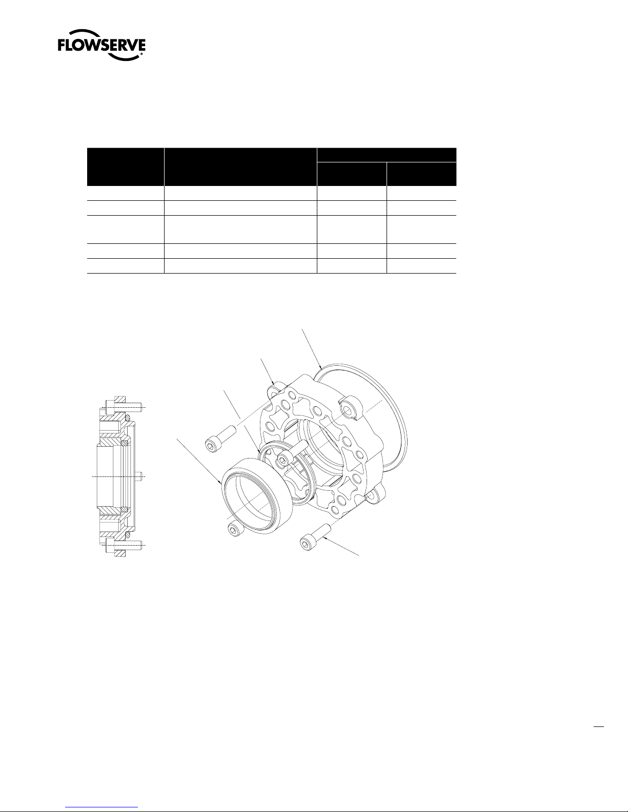
Limitorque MX Maintenance and Spare Parts FCD LMENIM2314-00 – 07/08
Swanson Flo | 800-288-7926 | www.swansonflo.com
4.9 Baseplate Type B4
Table 4.16 – Type B4 Baseplate Parts List
Part Number Description
11-1 Baseplate 1 1
11-2 Pilot 1 N/A
11-3 Seal
(85/140/150)
11-4 O-ring 1 1
11-5 Socket head cap screw 4 8
Figure 4.16 – Type B4 Baseplate (MX-05, -10, -20, and -40)
Quad ring 1 1
MX-05, -10, -20
and -40
Quantity
MX-85/140/150
59
flowserve.com
Page 68
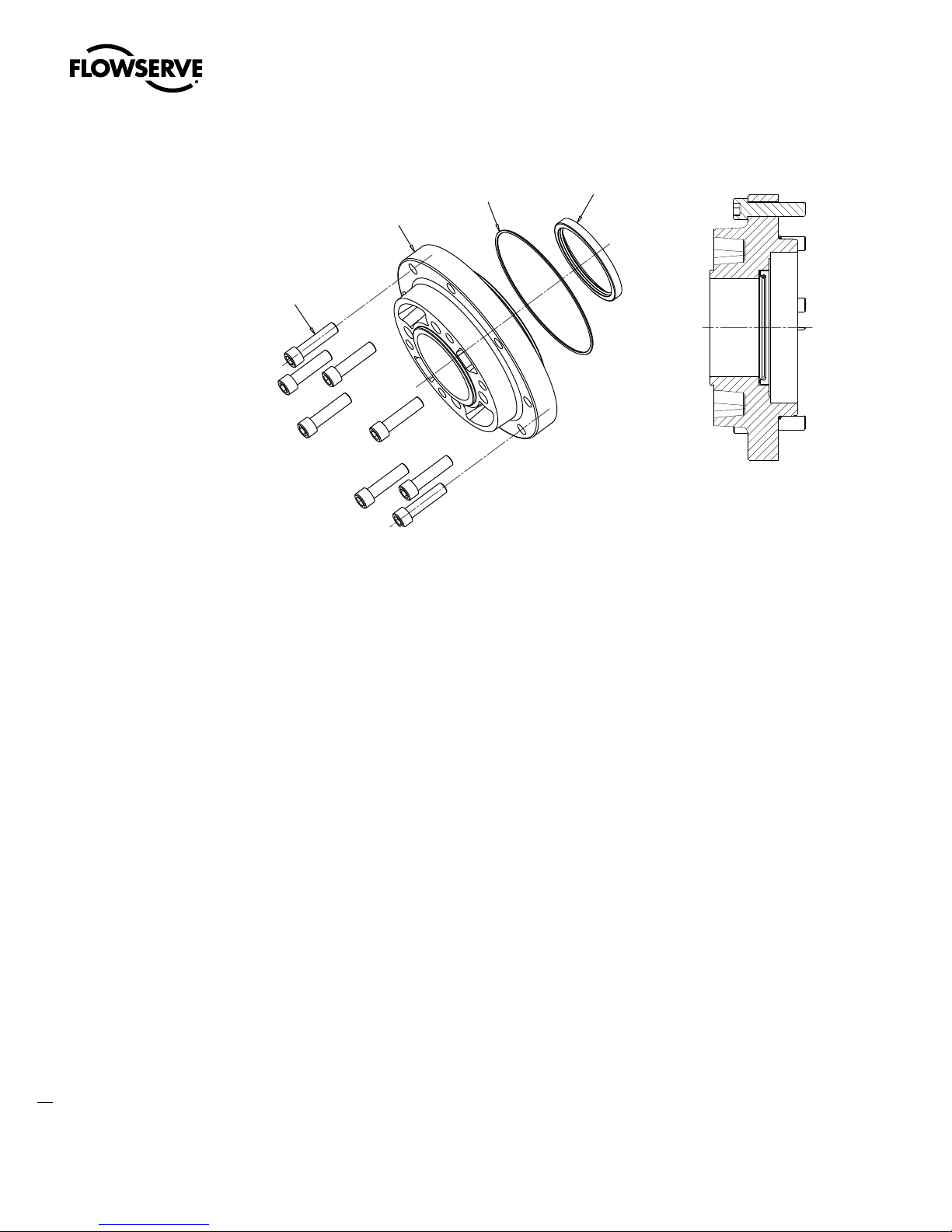
Limitorque MX Maintenance and Spare Parts FCD LMENIM2314-00 – 07/08
11-5
11-4
11-1
11-3
Swanson Flo | 800-288-7926 | www.swansonflo.com
Figure 4.17 – Type B4 Baseplate (MX-85, -140, and -150)
Stem Nuts (B4, B4E, and BL): Various stem nuts are used with the B4 baseplate:
1. B4 stem nut with variable bore and key
2. B4E stem nut for extended reach and variable bore and key
3. BL stem nut (6 or 36 splines)
The B4 stem nut is secured by a snap ring and the B4E and BL stem nuts are secured by a spiral-wound
ring. Reference the MX Installation Manual, LMENIM2306 for more information about stem nut options.
4.9.1 Removal
First Remove
1. Remove actuator from mounting adapter.
2. Drain oil.
3. Remove thrust base (subassembly #10) if fitted.
4. Remove stem nut.
60
Page 69

Limitorque MX Maintenance and Spare Parts FCD LMENIM2314-00 – 07/08
Swanson Flo | 800-288-7926 | www.swansonflo.com
STEP 1
WARNING: Potential to operate while dangerous mechanical parts are exposed during
c
subassembly removal. To prevent injury, turn off all power sources to actuator before
removing base plate assembly. Power sources may include main power or control
power.
Using a hex key, remove the four or eight
screws (#11-5).
1
11-5
STEP 2
WARNING: MX-85, -140, and -150. If handwheel worm gear assembly has previously
c
been removed, the drive sleeve assembly may slip and fall out of housing. Hold drive
sleeve assembly in from opposite end. See Section 4.12.1 and 4.12.2 for optional
removal and remounting.
Pull the baseplate (#11-1) off the drive sleeve.
2a
11-1
2b
61
flowserve.com
Page 70

Limitorque MX Maintenance and Spare Parts FCD LMENIM2314-00 – 07/08
Swanson Flo | 800-288-7926 | www.swansonflo.com
4.9.2 Remounting
STEP 3
CAUTION: To ensure actuator is fully secured on mounting plate, ensure baseplate (#11-1)
a
is tightened with the following torque values on mounting screws (#11-5):
MX-05 and -10 = 12 ft-lb (16 N m)
MX-20 and -40 = 24 ft-lb (32 N m)
MX-85, -140, and -150 = 90 ft-lb (114 N m)
Lightly lubricate the outside of the drive sleeve,
the quad ring or seal (#11-3), and O-ring
(#11-4) before remounting baseplate.
3
11-3
11-4
STEP 4
NOTE: (MX-20 only) Match outer bosses of baseplate with outer bosses of actuator housing before
mounting baseplate assembly.
NOTE: (MX-85, -140, and -150) Match mounting holes in baseplate to housing taps. Baseplate and
housing has one hole/tap that is not equally spaced.
Carefully push the baseplate assembly onto the
end of the drive sleeve, ensuring that the quad
ring or seal (#11-3) is not damaged. Align the
mounting holes and secure the baseplate with
the screws (#11-5).
4
62
Page 71
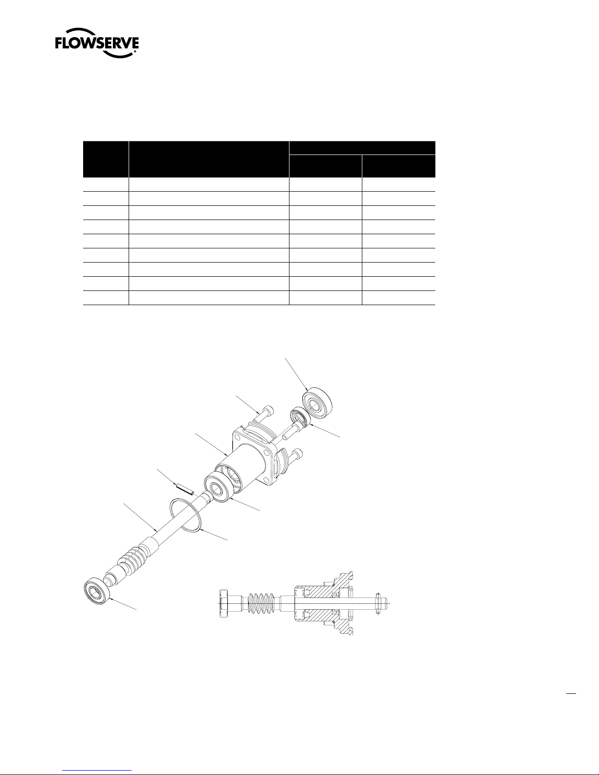
Limitorque MX Maintenance and Spare Parts FCD LMENIM2314-00 – 07/08
.9
.9
Swanson Flo | 800-288-7926 | www.swansonflo.com
4.10 Worm Shaft
Table 4.17 – Worm Shaft Parts List
Part
Number
3-1 Worm 1 1
3-2 Worm shaft cap 1 1
3-3 Ball bearing 1 1
3-4 Ball bearing 1 2
3-5 Ball bearing 1 N/A
3-6 Oil seal 1 1
3-7 O-ring 1 1
3-8 Pin 1 2
3-9 Socket head cap screw 4 4
Description
MX-05, -10, -20
and -40
Quantity
MX-85, -140, and
-150
Figure 4.18 – Worm Shaft (MX-05, -10, -20, and -40)
63
flowserve.com
Page 72

Limitorque MX Maintenance and Spare Parts FCD LMENIM2314-00 – 07/08
Swanson Flo | 800-288-7926 | www.swansonflo.com
4.10.1 Removal
First Remove
1. Remove actuator from mounting adapter.
2. Drain oil.
3. Remove motor (subassembly #4). (See Section 4.1.1.)
STEP 1
WARNING: Potential to operate while dangerous mechanical parts are exposed during
c
subassembly removal. To prevent injury, turn off all power sources to actuator before
removing worm shaft assembly. Power sources may include main power or control
power.
Remove the four screws (#3-9) that secure the
worm shaft cap (#3-2) to the actuator housing.
1
3-2
3-9
STEP 2
NOTE: The inboard bearing (#3-5 for MX-05, -20, -85, -140, and -150), at the end of the worm
shaft (#3-1) should remain in the actuator housing. If it falls out while removing the worm shaft
assembly, ensure it is replaced during remounting process.
Withdraw the complete worm shaft assembly
from the actuator housing, turning/rotating it
if necessary to free the worm from the worm
gear. Note the O-ring (#3-7) that is on the worm
shaft assembly. Replace at remounting.
2
3-1
3-7
(located
behind
flange)
64
Page 73

Limitorque MX Maintenance and Spare Parts FCD LMENIM2314-00 – 07/08
Swanson Flo | 800-288-7926 | www.swansonflo.com
4.10.2 Remounting
STEP 3
Check that the bearing (#3-5) is seated firmly in
the actuator housing.
STEP 4
NOTE: Lightly lubricate the O-ring (#3-7) before remounting worm shaft (subassembly #3).
Lightly lubricate the O-ring (#3-7) on the worm
shaft (subassembly #3). Push the complete
worm shaft assembly into the actuator housing
until the worm contacts the worm gear. Turn
the worm so it engages the worm gear and
continue rotating until the end of the worm
shaft is isolated in the inboard bearing (#3-4).
3
4a
3-7
MX-85, -140, AND -150 ONLY
Be sure the motor wiring harness is pushed
in, then rotate worm shaft cap (#3-2) around
so that tab is holding wiring harness in place.
See Section 5.11 for motor wiring harness
installation.
4b
Motor
wiring
harness
65
flowserve.com
Page 74

Limitorque MX Maintenance and Spare Parts FCD LMENIM2314-00 – 07/08
Swanson Flo | 800-288-7926 | www.swansonflo.com
STEP 5
Using a hex key, fit the four M6, M8, or M10
screws (#3-9) into the worm shaft cap (#3-2)
mounting holes and tighten.
5a
5b
3-9
3-2
66
Page 75

Limitorque MX Maintenance and Spare Parts FCD LMENIM2314-00 – 07/08
Swanson Flo | 800-288-7926 | www.swansonflo.com
4.11 Drive Sleeve (MX-05 and -10)
Table 4.18 – Drive Sleeve Parts List (MX-05 and -10)
Part Number Description Qty.
2-1 Drive sleeve 1
2-2 Worm gear 1
2-3 Encoder drive gear 1
2-4 Ball bearing 1
2-5 Retaining ring 1
2-6 Drive sleeve key 1
2-7 Clutch 1
2-8 Clutch spring 1
2-9 Retaining ring 1
Figure 4.19 – Drive Sleeve (MX-05 and -10)
67
flowserve.com
Page 76

Limitorque MX Maintenance and Spare Parts FCD LMENIM2314-00 – 07/08
Swanson Flo | 800-288-7926 | www.swansonflo.com
4.11.1 Removal
First Remove
1. Remove actuator from mounting adapter.
2. Drain oil.
3. Remove thrust base (subassembly #10) - if fitted.
4. Remove motor (subassembly #4). (See Section 4.1.1.)
5. Remove worm shaft (subassembly #3). (See Section 4.10.1.)
6. Remove base plate (subassembly #11). (See Section 4.9.1.)
STEP 1
WARNING: Potential to operate while dangerous mechanical parts are exposed during
c
subassembly removal. To prevent injury, turn off all power sources to actuator before
removing drive sleeve assembly. Power sources may include main power or control
power.
Once all other subassemblies are removed,
pull out the drive sleeve assembly (#2) until
the lower bearing (#2-4) is released from
the actuator housing. Remove drive sleeve
assembly from actuator.
1
2-4
68
Page 77

Limitorque MX Maintenance and Spare Parts FCD LMENIM2314-00 – 07/08
Lubricate
Lubricate
Swanson Flo | 800-288-7926 | www.swansonflo.com
4.11.2 Remounting
STEP 2
CAUTION: The drive sleeve surface serves as an oil-sealing surface. Use caution not to
a
scratch the drive sleeve while completing removal and remounting.
Lightly lubricate the top and bottom of the drive
sleeve assembly as shown.
2
STEP 3
Insert the drive sleeve assembly into the
actuator housing base until the lower bearing
(#2-4) is fully engaged in the housing (seated
on actuator shoulder). If the bearing is a tight
fit, gently tap the bottom of drive sleeve (#2-1)
with a mallet to properly seat.
STEP 4
Remount all removed subassemblies according to their remounting instructions in the following
order:
1. Base plate (subassembly #11). (See Section 4.9.2.)
2. Worm shaft (subassembly #3). (See Section 4.10.2.)
3. Motor (subassembly #4). (See Section 4.1.2.)
4. Thrust base (subassembly #10) - if fitted. (See Section 4.7.2.)
3
2-4
69
flowserve.com
Page 78

Limitorque MX Maintenance and Spare Parts FCD LMENIM2314-00 – 07/08
Swanson Flo | 800-288-7926 | www.swansonflo.com
4.12 Drive Sleeve (MX-20, -40, -85, -140, and -150)
Table 4.19 – Drive Sleeve Parts List (MX-20, -40, -85, -140, and -150)
Quantity
Part
Number
2-1 Drive sleeve 1 1 1
2-2 Worm gear 1 1 1
2-3 Encoder drive gear 1 1 1
2-4 Ball bearing 1 1 1
2-5 Retaining ring 1 N/A N/A
2-6 Drive sleeve key 1 1 1
2-7 Spacer N/A N/A 3
2-8 Ball bearing N/A N/A 2
2-9 Retaining Ring N/A N/A 1
Description
MX-20 and -40
MX-85, -140, and
-150
MX-85, -140, and
-150
10:1 and 13:1
Ratio
Figure 4.20 – MX-20 and -40 Drive Sleeve
70
Page 79

Limitorque MX Maintenance and Spare Parts FCD LMENIM2314-00 – 07/08
Swanson Flo | 800-288-7926 | www.swansonflo.com
Figure 4.21 – MX-85, -140, and -150 10:1 and 13:1 ratios
4.12.1 Removal
First Remove
1. Remove actuator from mounting adapter.
2. Drain oil.
3. Remove thrust base (subassembly #10) - if fitted. (See Section 4.8.1.)
4. Remove motor (subassembly #4). (See Section 4.1.1.)
5. Remove worm shaft (subassembly #3). (See Section 4.10.1.)
6. Remove top-mounted handwheel (#1-8) or side-mounted handwheel (subassembly #16). (See
7. Remove handwheel adapter (subassembly #12). (See Section 4.14.1.)
8. Remove clutch and clutch ring (subassembly #16). (See Section 4.15.1.)
9. Remove handwheel declutch (subassembly #5). (See Section 4.2.1.)
10. Remove base plate (subassembly #11). (See Section 4.9.1 or Section 4.12.1 for MX-85, -140, and -150)
Section 4.3.1 or 4.4.2.)
71
flowserve.com
Page 80

Limitorque MX Maintenance and Spare Parts FCD LMENIM2314-00 – 07/08
Swanson Flo | 800-288-7926 | www.swansonflo.com
WARNING: (MX-85, -140, and -150) The drive sleeve assembly may slip and fall out of
c
housing when removing baseplate assembly. Hold the drive sleeve assembly in from
opposite end when removing baseplate assembly. See optional drive sleeve and baseplate
removal Section 4.12.3 and 4.12.4.
STEP 1
WARNING: Potential to operate while dangerous mechanical parts are exposed during
c
subassembly removal. To prevent injury, turn off all power sources to actuator before
removing drive sleeve assembly. Power sources may include main power or control
power.
Once all other subassemblies are removed,
pull out the drive sleeve assembly (#2) until
the lower bearing (#2-4) is released from
the actuator housing. Remove drive sleeve
assembly from actuator.
1
2-4
MX-85, -140, and -150: Optional drive sleeve
and baseplate removal instructions.
STEP 2 (VIEWED FROM BASEPLATE SIDE OF ACTUATOR)
CAUTION: (MX-20 and -40) The drive sleeve surface serves as an oil sealing surface. Use
a
caution not to scratch the drive sleeve while completing removal and remounting.
TIP: To avoid interference between drive
sleeve assembly and encoder drive cartridge
(subassembly #14), turn flat on worm gear to
be parallel and on same side as encoder bevel
gear.
2
Worm
Gear Flat
Encoder
Drive
Cartridge
(14)
72
Page 81

Limitorque MX Maintenance and Spare Parts FCD LMENIM2314-00 – 07/08
Lubricate areas between
lines
Swanson Flo | 800-288-7926 | www.swansonflo.com
STEP 3 (VIEWED FROM TOP-MOUNTED HANDWHEEL SIDE OF ACTUATOR)
CAUTION: (MX-20 and -40 only) When
a
removing or remounting drive sleeve
assembly, take precaution not to bump
drive sleeve assembly against encoder
drive cartridge (subassembly #14).
3
Worm
Gear
Flat
TIP: Worm gear flat turned parallel with
encoder drive cartridge (subassembly #14) to
permit drive sleeve assembly removal.
Encoder
Drive
Cartridge
(14)
4.12.2 Remounting
STEP 4
NOTE: Before remounting drive sleeve assembly, ensure that bearing (#3-5) is in place in the
actuator housing. (Refer to motor subassembly #3 Step 1 for details.)
Lightly lubricate the top and bottom of the drive
sleeve assembly as shown.
4
STEP 5
CAUTION: (MX-20 and -40 only) When removing or remounting drive sleeve assembly,
a
take precaution not to bump drive sleeve assembly against encoder drive cartridge
(subassembly #14).
Push the drive sleeve assembly into the base
of the actuator housing until the lower bearing
(#2-4) is fully engaged in the housing up to
the shoulder. If the bearing is a tight fit, gently
tap the bottom of the drive sleeve (#2-1) with a
mallet to properly seat.
MX-85, -140, and -150: See Section 4.12.4
for optional remounting of drive sleeve and
baseplate.
5
2-4
2-1
73
flowserve.com
Page 82

Limitorque MX Maintenance and Spare Parts FCD LMENIM2314-00 – 07/08
Swanson Flo | 800-288-7926 | www.swansonflo.com
4.12.3 MX-85, -140, and -150 Optional Drive Sleeve
and Baseplate Removal
First Remove
1. Remove actuator from mounting adapter.
2. Drain oil.
3. Remove thrust base (subassembly #10) - if fitted. (See Section 4.8.1.)
4. Remove motor (subassembly #4). (See Section 4.1.1.)
5. Remove worm shaft (subassembly #3). (See Section 4.10.1.)
6. Remove top-mounted handwheel (#1-8) or side-mounted handwheel (subassembly #16).
(See Section 4.3.1 or 4.4.2.)
7. Remove handwheel adapter (subassembly #12). (See Section 4.14.1.)
8. Remove clutch and clutch ring (subassembly #16). (See Section 4.15.1.)
9. Remove handwheel declutch (subassembly #5). (See Section 4.2.1.)
STEP 1
Lay actuator on its side with the drive sleeve
horizontal. Using a hex key, remove seven of
the baseplate screws (#11-5).
STEP 2
Lay actuator on a table or suitable structure
with one of the screws (#11-5) hanging over
the edge. Remove screw. If needed, rotate
actuator around and remove all other screws.
1
2
74
Page 83

STEP 3
Swanson Flo | 800-288-7926 | www.swansonflo.com
With help, lift housing straight up and off
baseplate and drive sleeve assemblies.
STEP 4
Using the encoder gear (#2-3), lift drive sleeve
assembly out of the baseplate assembly. Turn
the drive sleeve assembly over (lugs of drive
sleeve up) and set down on table.
NOTE: The drive sleeve assembly is not held
together and will fall apart if set down on a lug
end of drive sleeve.
Limitorque MX Maintenance and Spare Parts FCD LMENIM2314-00 – 07/08
3
4a
2-3
4b
Lugs
2-3
75
flowserve.com
Page 84

Limitorque MX Maintenance and Spare Parts FCD LMENIM2314-00 – 07/08
Swanson Flo | 800-288-7926 | www.swansonflo.com
4.12.4 MX-85, -140, and -150 Optional Drive Sleeve
and Baseplate Remounting
STEP 1
Assemble drive sleeve assembly with drive sleeve lying on opposite end of lugs. Place worm gear
(#2-2), key (#2-6) and encoder drive gear (#2-3) onto the drive sleeve (#2-1). Place the ball bearing
(#2-4) into the baseplate assembly. See picture 4b in Section 4.12.3.
Lightly lubricate the bottom of the drive sleeve (#2-1) and the baseplate seal (#11-3).
Lift the drive sleeve assembly up, and holding the encoder drive gear (#2-2), turn the drive sleeve
over and place into the baseplate assembly. See picture 4a in Section 4.12.3.
STEP 2
With help, lift housing and place over the drive sleeve and baseplate assemblies. Match up the
mounting holes in the baseplate and housing. With the actuator sitting on the baseplate, slide the
unit over to the edge and mount one or two of the baseplate screws (#11-5). Turn unit over on its
side with the drive sleeve horizontal and secure the baseplate with the rest of the mounting screws.
NOTE: The drive sleeve is held in from the top by the handwheel worm gear. Without the handwheel
worm gear, the drive sleeve may slip out of position. Push the drive sleeve back into position from
the handwheel worm gear end. See pictures 3, 2, and 1, in that order, from Section 4.12.1.
STEP 3
Remount all removed subassemblies according to their remounting instructions in the following
order:
1. Base plate (subassembly #11). (See Section 4.9.2.)
2. Worm shaft (subassembly #3). (See Section 4.10.2.)
3. Handwheel declutch (subassembly #5). (See Section 4.2.2.)
4. Clutch and clutch ring (subassembly #16). (See Section 4.15.2.)
5. Handwheel adapter (subassembly #12). (See Section 4.14.2.)
6. Top-mounted handwheel (subassembly #1-8) or side-mounted handwheel (subassembly #13).
(See Section 4.3.2 or 4.4.3.)
7. Motor (subassembly #4). (See Section 4.1.2.)
8. Thrust base (subassembly #10) - if fitted. (See Section 4.8.2.)
76
Page 85
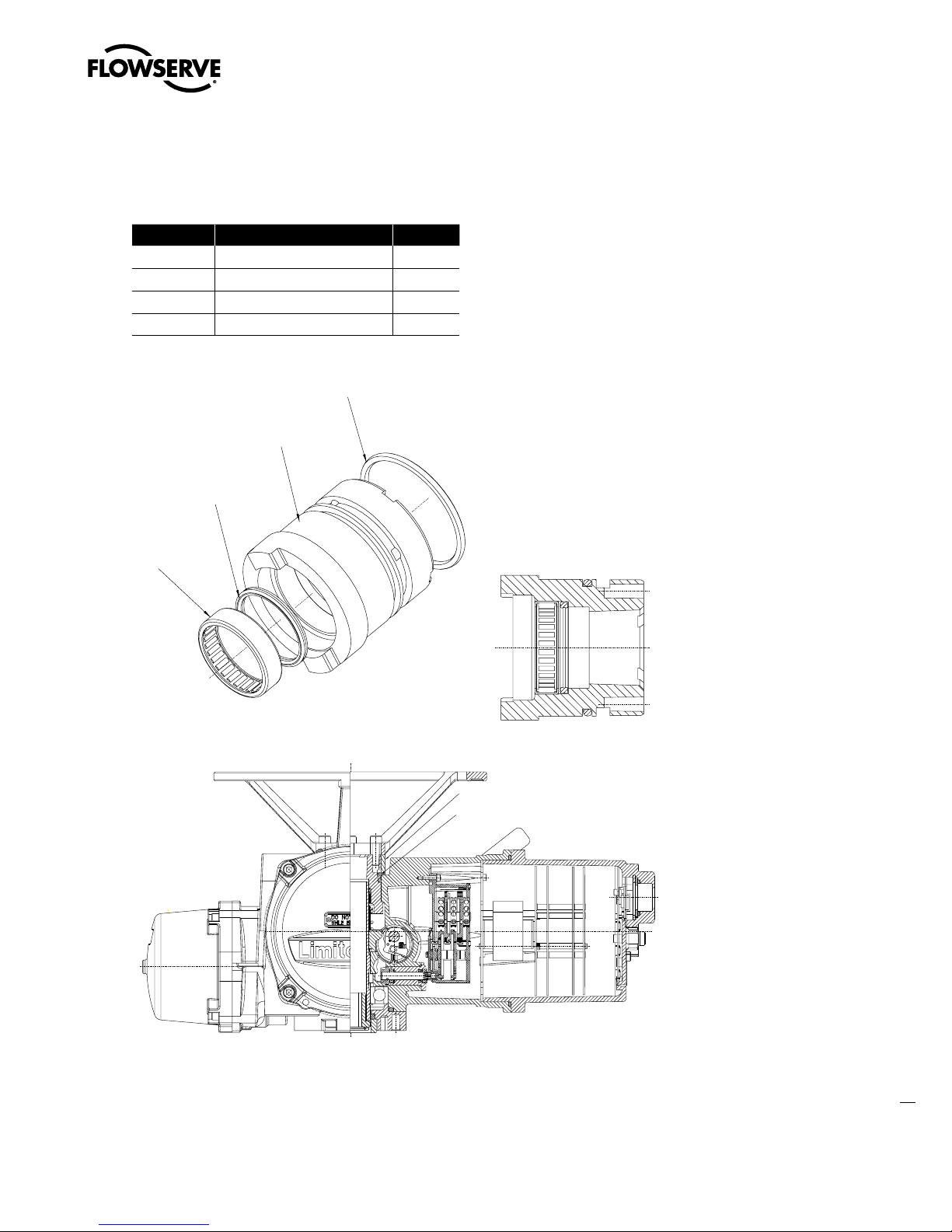
Limitorque MX Maintenance and Spare Parts FCD LMENIM2314-00 – 07/08
.9POMZ)BOEXIFFM4QBDFS
8BWF4QSJOH
Swanson Flo | 800-288-7926 | www.swansonflo.com
4.13 Handwheel Adapter (MX-05)
Table 4.20 – Handwheel Adapter Parts List (MX-05)
Part Number Description Qty.
12-1 Handwheel adapter 1
12-2 Needle bearing 1
12-3 Quad ring 1
12-4 O-ring 1
Figure 4.22 – Handwheel Adapter (MX-05)
Figure 4.23 – Handwheel (MX-05)
77
flowserve.com
Page 86

Limitorque MX Maintenance and Spare Parts FCD LMENIM2314-00 – 07/08
Swanson Flo | 800-288-7926 | www.swansonflo.com
4.13.1 Removal
First Remove
1. Remove actuator from mounting adapter.
2. Drain oil.
3. Remove top-mounted handwheel (#1-8). (See Section 4.3.1.)
4. Remove motor (subassembly #4). (See Section 4.1.1.)
5. Remove worm shaft (subassembly #3). (See Section 4.10.1.)
6. Remove base plate (subassembly #11). (See Section 4.9.1.)
7. Remove drive sleeve (subassembly #2). (See Section 4.11.1.)
STEP 1
WARNING: Potential to operate while dangerous mechanical parts are exposed during
c
subassembly removal. To prevent injury, turn off all power sources to actuator before
removing handwheel adapter assembly. Power sources may include main power or
control power.
Remove handwheel spacer (#1-9).
STEP 2
Unwind wave spring (#1-10) and remove.
1
1-9
2
1-10
78
Page 87

Limitorque MX Maintenance and Spare Parts FCD LMENIM2314-00 – 07/08
Swanson Flo | 800-288-7926 | www.swansonflo.com
STEP 3
NOTE: The handwheel adapter for the MX-05 is removed and introduced from the base of the
actuator housing.
Push adapter assembly (#12) from the top
of the actuator out through the bottom of the
actuator housing.
3
Handwheel
Adapter
Assembly 12
4.13.2 Remounting
STEP 4
NOTE: Lightly lubricate quad rings/O-rings before remounting subassemblies.
With handwheel screw taps facing toward the
nameplate side of the actuator, slide handwheel
adapter assembly (#12) into the actuator housing’s drive sleeve bore. Use hammer handle
or similar device to push handwheel adapter
assembly against shoulder inside actuator
housing.
STEP 5
Once handwheel adapter assembly is installed
in actuator housing, wind wave spring (#1-10)
into groove on the handwheel adapter.
4
5
Handwheel
Adapter
Screw Taps
1-10
79
flowserve.com
Page 88

Limitorque MX Maintenance and Spare Parts FCD LMENIM2314-00 – 07/08
Swanson Flo | 800-288-7926 | www.swansonflo.com
STEP 6
Slide handwheel spacer (#1-9) over handwheel
adapter assembly, ensuring wave spring
(#1-10) is seated in groove of the handwheel
spacer.
STEP 7
Remount all removed subassemblies according to the remounting instructions in the following
order:
1. Drive sleeve (subassembly #2). (See Section 4.11.2.)
2. Base plate (subassembly. #11). (See Section 4.9.2.)
6
1-10
1-9
3. Worm shaft (subassembly. #3). (See Section 4.10.2.)
4. Motor (subassembly #4). (See Section 4.1.2.)
5. Top-mounted handwheel (#1-8). (See Section 4.3.2.)
NOTE: After completing handwheel assembly procedure, turn handwheel enough to ensure
wave spring is not pinched between actuator housing and handwheel spacer. If it is pinched,
remove handwheel (#1-8) and handwheel spacer (#1-9) to reseat the wave spring (#1-10) into
the grove on the handwheel spacer. Install handwheel.
6. Add oil.
80
Page 89
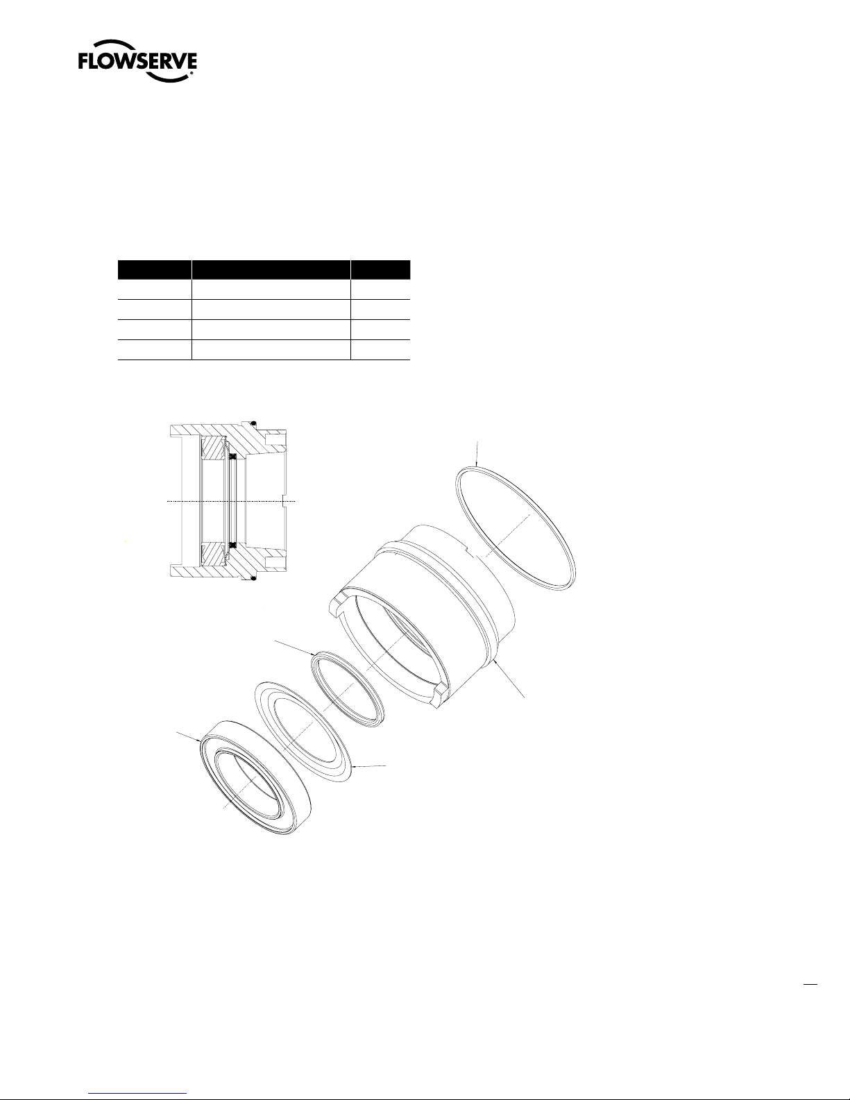
Limitorque MX Maintenance and Spare Parts FCD LMENIM2314-00 – 07/08
6OJRVFUP.9IBOEXIFFM
BEBQUFSPOMZSFUBJOTRVBESJOH
Swanson Flo | 800-288-7926 | www.swansonflo.com
4.14 Handwheel Adapter (MX-10, -20 and -40)/
Handwheel Worm Gear (MX-10, -20, -40, -85,
-140, and -150)
Table 4.21 – Handwheel Adapter Assembly Parts List
Part Number Description Qty.
12-1 Handwheel adapter 1
12-2 Ball bearing 1
12-3 Quad ring 1
12-4 O-ring 1
Figure 4.24 – Handwheel Adapter Assembly
81
flowserve.com
Page 90

Limitorque MX Maintenance and Spare Parts FCD LMENIM2314-00 – 07/08
Swanson Flo | 800-288-7926 | www.swansonflo.com
Table 4.22 – Handwheel Worm Gear Assembly Parts List
Part Number Description Qty.
12-1 Handwheel worm gear 1
12-2 Ball bearing 1
12-3 Quad ring 1
12-4 O-ring 1
12-5 Handwheel adapter 1
Figure 4.25 – Handwheel Worm Gear Assembly
82
Page 91

Limitorque MX Maintenance and Spare Parts FCD LMENIM2314-00 – 07/08
Handwheel Worm Gear
Adapter (12-1)
Handwheel Adapter
(12-5)
Swanson Flo | 800-288-7926 | www.swansonflo.com
4.14.1 Removal
First Remove
1. Top-mounted handwheel (#1-8) or side-mounted handwheel (subassembly #13). (See Section
4.3.1 or 4.4.2.)
NOTE: Before removing handwheel and handwheel adapter assembly, turn handwheel
approximately 45° to permit declutch lever to fully engage therefore making handwheel assembly
easy to remove.
The handwheel adapter assembly and the
handwheel worm gear assembly procedures
are interchangeable. The parts within the
assembly are the same with exception to the
handwheel adapter (#12-1) and the handwheel
worm gear adapter (#12-1). The handwheel
adapter assembly is used when the handwheel
is top-mounted. The handwheel worm gear
assembly is used when the handwheel is
side-mounted.
STEP 1
WARNING: Potential to operate while dangerous mechanical parts are exposed during
c
subassembly removal. To prevent injury, turn off all power sources to actuator before
removing handwheel adapter assembly. Power sources may include main power or
control power.
Remove the four screws (#1-33) from the
retainer plate (#1-32).
1
1-33
1-32
83
flowserve.com
Page 92

Limitorque MX Maintenance and Spare Parts FCD LMENIM2314-00 – 07/08
Swanson Flo | 800-288-7926 | www.swansonflo.com
STEP 2
Lift off the retainer plate (#1-32).
STEP 3
Pull the handwheel adapter assembly (#12) out
of the actuator housing.
2
3
STEP 4 (MX-10 ONLY)
Lift out wave spring (#1-10) from the actuator
housing.
4.14.2 Remounting
STEP 5 (MX-10 ONLY)
Insert the wave spring (#1-10) onto the
shoulder of the actuator housing.
12
4
1-10
5
1-10
84
Page 93

Limitorque MX Maintenance and Spare Parts FCD LMENIM2314-00 – 07/08
Swanson Flo | 800-288-7926 | www.swansonflo.com
STEP 6
NOTE: Lightly lubricate quad rings/O-rings before remounting subassemblies.
Fit the handwheel adapter assembly (#12) into
the top of the actuator housing. Slowly rotate
the assembly as it approaches its lower position in the actuator; this will allow the quad ring
(#12-3) to ease over the end of the drive sleeve
avoiding damage to the quad ring.
STEP 7 (MX-20 AND -40 ONLY)
Place the O-ring (#12-4) around handwheel
adapter, pressing the O-ring into the slot
between the handwheel adapter assembly (#12)
and the actuator housing (approximately every
15° to 30°) until the O-ring seats into slot.
Quad Ring (12-3)
6
Located Inside
Handwheel Adapter
12
7
12-4
85
flowserve.com
Page 94

Limitorque MX Maintenance and Spare Parts FCD LMENIM2314-00 – 07/08
Swanson Flo | 800-288-7926 | www.swansonflo.com
STEP 8
NOTE: Retainer plate (#1-32) may sit slightly above actuator housing until screws are retightened.
WARNING: The MX-10 through -150 require precaution to prevent damage to the
c
declutch latch. This applies while installing the handwheel adapter/gear assembly
(#1-35), retainer plate (#1-32) and screws (#1-33). If the unit is in the clutched position
(handwheel operation) during assembly, a lug-to-lug condition can result between the
clutch and the handwheel adapter/gear. In this situation the latch will be compressed
and damaged when the plate screws are tightened.
Assure the clutch lugs are fully engaged to the
bronze gear lugs before installing the handwheel adapter/gear assembly. The latch must
be rotated down and not holding the clutch
off the bronze worm gear. When installing the
handwheel adapter/gear, ensure these lugs fall
between the clutch lugs. This position will allow
the handwheel adapter/gear lugs to be fully
engaged to the clutch lugs. The final step is to
install the retaining plate and socket head cap
screws.
8
1-32
Place the retainer plate (#1-32) on the top of
the actuator housing. Align the mounting taps,
and secure with screws (#1-33).
STEP 9 (MX-10, -20 AND -40)
Install handwheel (#1-8) onto handwheel
adapter assembly (#12), align the handwheel
with screw holes and tighten the four socket
head cap screws (#1-11).
or
Install side-mounted handwheel (subassembly
#13) according to remounting instructions
detailed in Section 4.4.3.
9
1-8
86
Page 95

Limitorque MX Maintenance and Spare Parts FCD LMENIM2314-00 – 07/08
%SJWF4MFFWF
"TTFNCMZ
%SJWF4MFFWF
"TTFNCMZ
)PVTJOH
#BTFQMBUF
"TTFNCMZ
Swanson Flo | 800-288-7926 | www.swansonflo.com
4.15 Clutch and Clutch Ring Components
(MX-20, -40, -85, -140, and -150)
Table 4.23 – Clutch and Clutch Ring Components Parts List
Part Number Description Qty.
1-38 Clutch 1
1-37 Clutch ring 1
1-39 Clutch spring 1
1-40 Spring spacer 1
Figure 4.26 – MX-20 and -40 Clutch
and Ring Components
Figure 4.27 – MX-85, -140, and -150 Clutch
and Ring Components
87
flowserve.com
Page 96

Limitorque MX Maintenance and Spare Parts FCD LMENIM2314-00 – 07/08
Swanson Flo | 800-288-7926 | www.swansonflo.com
4.15.1 Removal
First Remove
1. Drain oil.
2. Remove top-mounted handwheel (#1-8) or side-mounted handwheel (subassembly #13). (See
Section 4.3.1, Section 4.4.2, or Section 4.5.2.)
3. Remove handwheel adapter (subassembly #12). (See Section 4.14.1.)
STEP 1
WARNING: Potential to operate while dangerous mechanical parts are exposed during
c
subassembly removal. To prevent injury, turn off all power sources to actuator before
removing clutch and clutch ring components. Power sources may include main power or
control power.
Remove spring spacer (#1-40).
1
88
STEP 2
Remove clutch spring (#1-39) that is positioned over the drive sleeve assembly (#2).
STEP 3
Remove clutch (#1-38).
1-40
2
1-39
2
3
1-38
Page 97

Limitorque MX Maintenance and Spare Parts FCD LMENIM2314-00 – 07/08
Swanson Flo | 800-288-7926 | www.swansonflo.com
STEP 4
Remove clutch ring (#1-37).
MX-85, -140, and -150 (removing clutch ring
assembly):
While pulling up on clutch ring end with socket
head cap screw (#15-9), rotate latch 90° and
slide clutch ring over drive sleeve and out of
housing.
4
4.15.2 Remounting
WARNING: Potential to operate while dangerous mechanical parts are exposed during
c
subassembly removal. To prevent injury, turn off all power sources to actuator before
removing clutch and clutch ring components. Power sources may include main power or
control power.
1-37
STEP 5A (MX-20 AND -40 ONLY)
Remounting clutch ring
Fit the clutch ring (#1-37) over the drive sleeve
with the tangs (forked protrusion) facing down.
Seat tangs over declutch cam (see pictures 5a
and 5a1 at right). See warning note in Section
4.14.2, Step 8.
5a
5a1
Declutch Cam
Clutch
Tangs on
Clutch
Ring
(1-37)
Tangs
89
flowserve.com
Page 98
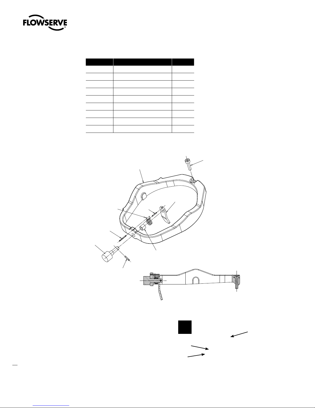
Limitorque MX Maintenance and Spare Parts FCD LMENIM2314-00 – 07/08
Swanson Flo | 800-288-7926 | www.swansonflo.com
Table 4.24 – Clutch Ring Assembly Parts List
Part Number Description Qty.
15-1 Clutch ring 1
15-2 Roller 1
15-3 Roll pin 1
15-4 Spacer 1
15-5 Latch spring 1
15-6 Roll pin 1
15-7 Latch 1
15-8 Roll pin 1
15-9 Socket head cap screw 1
Figure 4.28 – MX-85, -140, and -150 Clutch Ring
STEP 5B (MX-85, -140, AND -150 ONLY)
90
5b
15-2
15-9
15-7
Page 99

STEP 5B, C, D (MX-85, -140, AND -150)
Swanson Flo | 800-288-7926 | www.swansonflo.com
CONTINUED
Fit the clutch ring (#1-37) over the drive sleeve.
With the roller (#15-2) down and holding
the latch (#15-7) 90° from free position. See
picture 5c.
NOTE: The clutch ring socket head cap screw
(#15-9) must fit into hole in housing to keep
ring from rotating. See picture 5d. See warning
Note in Section 4.14.2, Step 8.
Limitorque MX Maintenance and Spare Parts FCD LMENIM2314-00 – 07/08
5c
STEP 6
Slide clutch (#1-38) over drive sleeve assembly.
STEP 7
Slide spring (#1-39) over drive sleeve
assembly.
5d
6
7
Housing
Hole for
Clutch Ring
Screw for
AntiRotation of
Clutch Ring
Assembly
1-38
1-39
91
flowserve.com
Page 100

Limitorque MX Maintenance and Spare Parts FCD LMENIM2314-00 – 07/08
Swanson Flo | 800-288-7926 | www.swansonflo.com
STEP 8
Slide spring spacer (#1-40) over drive sleeve
assembly.
STEP 9
Remount removed subassemblies according to their remounting instructions in the following order:
1. Handwheel adapter assembly (subassembly #12). See Section 4.14.2.
2. Top-mounted handwheel (#1-8) or side-mounted handwheel (subassembly #13). See Section
4.3.2 or Section 4.4.3 (MX-20), or Section 4.5.3 (MX-40).
8
1-40
92
 Loading...