

Page 1

The Pulsair III is a digital positioner designed primarily for
controlling adjustable valves. The positioner can be used with single
or double action 39 series actuators.
The Pulsair III Watertight Positioner (L93W) can be equipped with
modules for feedback, limit switches, sensors, and a pressure
gauge block.
The Pulsair III Hazardous Location Positioner (4L93Z) does not
allow for switch/sensor options. However, the feedback (4–20 mA
output) option is included as standard.
For the L93W, modules can be factory assembled before delivery or
fitted later.
The modules for feedback (4–20 mA output) and limit
switches/sensors can contain the following:
Feedback (4–20 mA output) and/or one of the following functions:
• Two mechanical switches (code M2)
• Two proximity (reed) switches (code R2)
• Two Namur sensors (code P2)
Storage Instructions
PULSAIR III positioners are precision instruments which should be
stored and handled accordingly to avoid problems or damage.
Electro-pneumatic positioners contain electronic components which
can be damaged by exposure to excessive water. Appropriate
precautions should be taken to protect units while in storage.
Warehouse Storage
Stored in original shipping containers, units should be stored in an
environmentally controlled area, i.e., clean, cool (15–26°C, 60–80°F)
and dry, out of direct sunlight or weather exposure.
Field Storage
NOTE: Once the air supply to the positioner is connected and turned
on, internal air bleed will prevent the ingress of moisture and protect
the unit from corrosion. It is recommended that the air supply be
left on at all times.
• If units are installed immediately, turn, and leave on,
the air supply.
• If positioners must be stored outdoors, tighten all
covers which may have loosened in shipment and
make sure all open enclosure points are sealed.
Positioners should be wrapped and sealed, air and watertight with
desiccant inside the plastic, units should be securely covered with an
opaque cover and not exposed to direct sunlight, rain or snow.
Units should have all ports sealed and be protected from direct
exposure to weather. For long term storage (>1 month) or overseas
shipment, units should be protected with plastic and desiccant.
Potential Damage to Mechanism
When units are stored in hot, humid climates, the daily
heating/cooling cycle will cause air to expand/contract and be drawn
in and out of the positioner housing. Dependent on the local
temperature variations, humidity, dew points and time in storage,
condensation could occur and accumulate inside causing erratic
operation or failure due to water and corrosion. The potential for
condensation damage is especially high in southern climates and
aggravated if units are exposed to direct sunlight.
For further assistance, please contact you nearest Worcester
distributor.
Worcester Controls
19860-C
Series 93 PULSAIR III
Digital Electronic Positioner
Installation, Operation and Maintenance Instructions
Page 2

2 Series 93 PULSAIR III Digital Electronic Positioner Installation, Operation and Maintenance 19860-C
Flow Control Division
Worcester Controls
Installation
If Positioner is not already mounted to the 39 Series Actuator, mount
per part 1:
1. Attaching the Positioner to the 39 Series Actuator
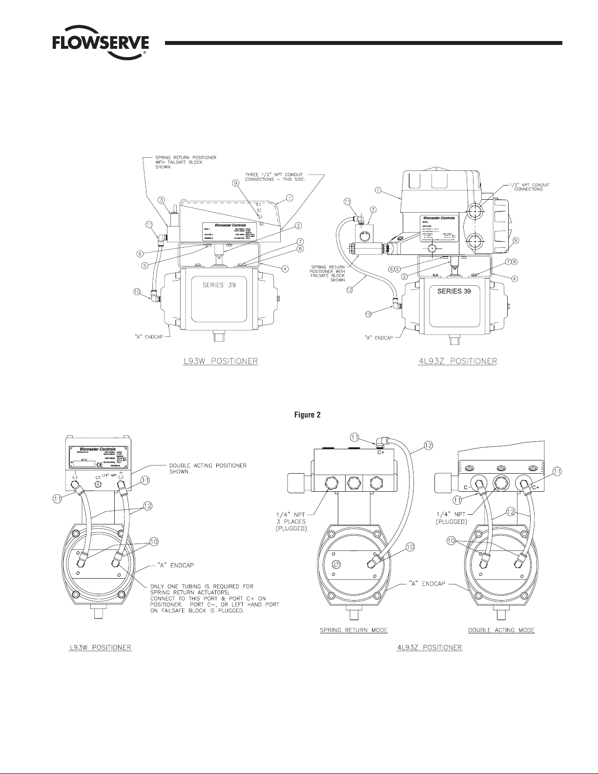
(refer to Figure 1)
Remove positioner (1) from the box. Coupling (spindle adapter)
(2), and failsafe block (3) (used with spring return only) are
loose inside the box.
Insert the round end of the coupling (2) into the bottom of the
positioner making sure that the spline seats properly, and that
the coupling is firmly seated in the positioner shaft. There is a
spring loaded ring on the coupling which must fit into a groove
inside the positioner shaft.
Install the mounting bracket (4) onto the bottom of the
positioner using four M6 X 12 mm screws (5) and lock washers
(6) included in the bracket kit. Align the bracket with the
positioner.
Rotate the coupling to align the coupling tang with the slot in
the output shaft on top of the actuator. Attach the
positioner/bracket/ coupling assembly to the actuator using
four M5 x 12 mm screws (7) and lock washers (8). The air
inlet porting on the positioner must be on the same end as the
“A” endcap (air inlet end) of the actuator.
Using an indelible marker, mark the 39 actuator model number
and output torque (as found on 39 actuator nameplate) on the
white mylar label supplied with the positioner and attach it to the
side of the actuator opposite the nameplate side.
2. If not already attached, attach the Failsafe Block to the Positioner
(for spring return only)
Refer to figure 1.
Install three O-rings (for L93W only) into the failsafe block (3).
Mount the failsafe block (3) to the end of the positioner (1) with
the ‘C+’ port to the right using the two screws provided with the
L93W, or three each of fittings and bushings and six grommets
with the 4L93Z.
3. Air Connections (Refer to Figures 1 and 2)
IMPORTANT: Use industrial air (or other non-flammable gas), Which
must be dry and oil free. See PULSAIR III Technical Reference
Manual (Part No. 19990) for other air supply requirements and
technical data.
Series 93 PULSAIR III mounting kits contain two elbow fittings
for actuator, two elbow and two straight fittings for positioner,
and one length of
1
/
4
" O.D. tubing. The length of tubing will be cut
to suit the assembly.
Note: Pipe thread sealant may be used on the threads of the fittings
(do not allow thread sealant to contaminate the internal air passages
of the positioner). Fluoropolymer tape thread sealant should not be
used.
If not already plumbed, plumb the Positioner to the Actuator
Connect the elbow air fitting(s) (10) to the actuator “A” end cap.
Connect
1
/
4" NPT straight or elbow air fitting(s) (11) into the
positioner.
For spring return, use ‘C+’ port on the failsafe block, and make
sure that there is a plug in the unidentified port on the failsafe
block (far left position).
For double acting actuator, use the ‘C+’ and ‘C-’ ports on the
positioner. Note that no failsafe block is necessary.
Cut the tubing (12) provided to as short a length as possible that
will still reach comfortably from the positioner to the actuator.
Connect the tube(s) to their respective actuator and positioner
port fittings.
4. Connect 80 psig Supply Air to Positioner (Refer to Figure 2)
Remove plastic plug from the positioner (or failsafe block) port
‘S’ and discard.
Connect an air supply line to the
1
/
4" NPT ‘S’ port.
5. Installation of M2, R2, or P2 Switch/Sensor and/or 4-20 mA
Output Options (for L93W Positioner only)
1. If not already installed, install optional switches/sensors
and/or 4–20 mA output into the positioner (if applicable):
2. The option kit includes a circuit board with switches
mounted, two mounting screws, and a cam assembly with
two mounting screws installed.
3. Refer to the PULSAIR III Technical Reference Manual (Part
No. 19990) for assembly illustrations.
4. Remove the outside positioner cover.
5. Remove the plastic, yellow and black, position indicator. The
indicator is a press fit and can be removed by prying up
using fingers or small screwdrivers.
6. Remove the two inside cover attachment screws located at
the terminal strip end of the inside positioner cover.
7. Carefully lift the inside cover to clear the yellow push button
switches, and slide the inside cover towards the terminal
strip to remove. The inside cover has a lip which is under
the clear filter cover.
8. Install the circuit board over the positioning shaft, and align
the board socket with the twelve pins on the positioner
motherboard. Press firmly to seat the contacts.
9. Install the two mounting screws to hold the circuit board to
the positioner motherboard.
ACTUATOR SIZE PORT THREAD (NPT)
10–20
1
/
8"
25–42
1
/
4"
Page 3
19860-C Series 93 PULSAIR III Digital Electronic Positioner Installation, Operation and Maintenance 3
Flow Control Division
Worcester Controls
Figure 1
! !"#
$
% &'( ) % &
% '( ) %
*
Figure 2
C+
-
C
C+
Page 4

4 Series 93 PULSAIR III Digital Electronic Positioner Installation, Operation and Maintenance 19860-C
Flow Control Division
Worcester Controls
10. Install the cam assembly with the lobes oriented towards the
terminal strip end of the positioner, over the positioner shaft.
Move the switch contact arms (M2 mechanical switches
only) aside so that the cam assembly can sit all the way
down on the shaft.
NOTE: Cam assembly does not have to be installed, if switches are
not going to be used and only the 4–20 mA output is to be utilized.
CAUTION: For m2 mechanical switches, Do not force the CAM
assembly down without moving the contact arms, as damage to
the limit switch may result.
11. Rotate the cam assembly to line up the cam assembly
attachment screws and tighten the screws finger tight. You
should still be able
to move the cams for alignment before final tightening of the
attachment screws.
6. Electrical Connections
See wiring diagram (9) on inside of cover (refer to Figure 1 for
wiring label location) or Figure 3 below.
a WARNING: In a hazardous environment where there is a risk of
explosion, electrical connections must comply with the relevant
regulations.
Remove the positioner cover (if not already done) for connecting
signal source and for optional board wiring. NOTE: For 4L93Z
units there are separate covers for programming and electrical
connections.
Connect a 4–20 mA signal source to terminal locations 1
(positive lead) and 2 (negative lead).
Adjust the signal source to between 8 and 20 mA.
For 4–20 mA output module option
(for L93W & 4L93Z Positioners)
Connect a 10-28 volt DC source to terminal locations 11
(positive) and 12 (negative return from load).
For M2 Limit or R2 proximity switch option
(for L93W Positioner only)
M2- Connect 125 VAC- 3 amp maximum, or 30 VDC - 2 amp
maximum wiring to terminal locations as follows:
R2 - Connect 125 VAC or 30 VDC - 250 mA maximum wring to
terminal locations as follows:
Terminal Locations:
3 Clockwise switch, normally open - Switch #1
4 Clockwise switch, normally closed - Switch #1
5 Clockwise switch, common - Switch #1
6 Counter-Clockwise switch, normally open - Switch #2
7 Counter-Clockwise switch, normally closed - Switch #2
8 Counter-Clockwise switch, common - Switch #2
For P2 Namur Sensor Option
(for L93W Positioner only)
Connect appropriate Namur amplifier (rated for 5–25 VDC
output) wiring to terminal locations as follows:
Terminal Locations:
3 Clockwise Sensor, negative - Sensor #1
4 Clockwise Sensor, positive - Sensor #1
6 Counter-Clockwise Sensor, negative - Sensor #2
7 Counter-Clockwise Sensor, positive - Sensor #2
For open collector alarm output
Connect 8–28 VDC wiring to terminal location 13 (positive) and
14 (negative).
Menus and Pushbuttons
The positioner is controlled using the five pushbuttons and the
display, which are accessible when the positioner cover is removed.
For normal functioning, the display shows the current position value.
Press the ESC button for two seconds to display the main menu.
Figure 3
Page 5

19860-C Series 93 PULSAIR III Digital Electronic Positioner Installation, Operation and Maintenance 5
Flow Control Division
Worcester Controls
Use the UP and DOWN pushbuttons to browse through the main
menu and the sub-menus.
The main menu is divided up into a basic menu, and a full menu.
Other functions:
ESC - Exit the menu without making any changes (as long as any
changes have not been confirmed with OK).
FUNC - To select function and change parameters.
OK - To confirm selection or change of parameters.
MENU INDICATOR - Displays the location of the current menu
row in the menu.
IN SERVICE - The positioner is following the input signal. This is
the normal status when the positioner is working.
OUT OF SERVICE - The positioner is not following the input
signal. Critical parameters can be changed.
MANUAL- The positioner can be adjusted manually using the
push buttons.
UNPROTECTED- Most of the parameters can be changed when
the positioner is in the ‘Unprotected’ mode. However, critical
parameters are locked when the positioner is in the ‘In Service’
mode.
MENU STATUS INDICATORS - On the left side of the display there
are indicators that mean the following:
Top Left (on and flashing) - OUT OF SERVICE
Middle Left (on and flashing) - MANUAL MODE
Bottom Left (on) - UNPROTECTED MODE
Calibration
The following steps are used to calibrate the unit for verification of
installation. Specific programming and advanced features are
explained in the Technical Reference Manual (Part No. 19990).
1. Apply 80 psig air to the supply ‘S’ port of the positioner.
2. Set the input signal source to 10–12 milliamps.
3. Look at the display- it should read “BASIC MENU” over
“CALIBRATE”
4. Momentarily depress the pushbuttons in the following sequence
to begin the auto-calibration routine.
FUNC, FUNC, OK, OK, OK, OK, OK
5. At this point, the positioner will begin it’s auto-calibration
routine.
Note: If the display reads ‘increase C+ damper’, there is too much air
volume flowing to the actuator (speed is too high). Adjust the
damper by turning the C+ damper screw clockwise
1
/
2 turn and press
the ‘ok’ button. Refer to the inside electrical cover for location of the
C+ damper screw. Adjust until the unit performs the auto-calibration
routine without getting the ‘increase C+ damper’ message.
6. For double acting actuators, both the ‘C+’ and ‘C-’ damper
screws may need adjusting. Follow the display instructions
accordingly.
7. At the end of the auto-calibration routine, press and hold the OK
pushbutton for three seconds to place the unit back to ‘IN
SERVICE’.
8. If an internal leak is detected during the auto-calibration
routine, the display will show ‘AIR LEAK DETECTED’. The next
screen will show ‘ESC=ABORT’ and ‘OK=GO ON’. Press the ESC
to stop the calibration routine or OK to allow you to continue
the calibration and ignore the leak.
9. When the unit is back ‘IN SERVICE’, the positioner should
respond to the 4–20 mA input signal with 4 mA= Full CW and 20
mA=Full CCW positions.
4–20 mA Output Option Calibration
Attach a current meter (4–20 mA range) in line with the positive
meter lead connected to terminal strip position 12, the negative
meter lead connects to the negative power supply (10–28 volts DC)
lead, and the positive power supply lead connects to terminal strip
position 11.
1. Turn on the ammeter and power supply.
2. Press and hold the ESC pushbutton for three seconds to get the
display back to the root menu. Display should show ‘BASIC
MENU’ over ‘MAN/AUTO’.
3. Press the DOWN button twice and display should read ‘BASIC
MENU’ over ‘SHIFT MENU’.
4. Press the FUNC button once and display should read ‘Full menu’
over ‘no’.
5. Press the DOWN button and display should read ‘Full menu’
over ‘yes’.
6. Press the OK button and display should read ‘FULL MENU’ over
‘SHIFT MENU’.
7. Press the DOWN button four (4) times and display should read
‘FULL MENU’ over ‘TUNING’.
8. Press the FUNC button and the display should read ‘TUNING’
over ‘Close time’.
9. Press the DOWN button three (3) times and display should read
‘TUNING’ over ‘Expert’.
10. Press the FUNC button once and the display should read ‘Expert’
over ‘togglestep’.
11. Press the DOWN button three (3) times and the display should
read ‘Expert’ over ‘Ref Cal’.
12. Press the FUNC button once and the display should read ‘Ref
Cal’ over ‘Set point’.
13. Press the DOWN button four (4) times and the display should
read ‘Ref Cal’ over ‘Transm’.
Page 6

6 Series 93 PULSAIR III Digital Electronic Positioner Installation, Operation and Maintenance 19860-C
Flow Control Division
Worcester Controls
14. Press the FUNC button once and the display should read
‘Transm’ over ‘Transm low’.
15. Press the FUNC button once and display should read ‘Transm
low’ over ‘LO=4.0 mA’.
16. Press the UP or DOWN button as necessary to adjust the output
signal to read 4.0 mA, or as close to 4.0 as is possible.
17. Press the OK button to accept the setting. The display should
read ‘Transm low’ over ‘UPDATED’ for a brief moment.
18. Press ESC and display should read ‘Transm’ over ‘Transm low’.
19. Press DOWN once and display should read ‘transm’ over
‘Transm hi’.
20. Press FUNC button once and the display should read ‘Transm hi’
over ‘HI=20.0 mA’.
21. Press the UP or DOWN button as necessary to adjust the output
signal to read 20.0 mA, or as close to 20.0 as is possible.
22. Press the OK button to accept the setting. The display should
read ‘Transm hi’ over ‘UPDATED’ for a brief moment.
23. Press the ESC button for 2-3 seconds and the display will return
to the ‘FULL MENU’ over ‘MAN/AUTO’ screen.
24. Disconnect the calibration ammeter from terminal positions 11
and 12, and attach your readout leads to terminal position 11
(positive) and 12 (negative).
Limit (M2) and Proximity (R2) Switch Cam Adjustment
(for L93W Positioner only)
1. Connect an ohmmeter to terminal position 3 (switch 1 normally open) and terminal position 5 (switch 1 - common).
2. Input a 4.2 mA signal so that the positioner is in the clockwise
position.
3. Using a screwdriver or similar tool, use the notch on the lower
cam and rotate the cam counter-clockwise away from the
switch and then clockwise until switch 1 closes. The ohmmeter
indication changes from infinite to a low reading that indicates
continuity through the switch.
4. Input a 19.8 mA signal so that the positioner is in the counterclockwise position.
5. Connect the ohmmeter leads to terminal position 6 (switch 2 normally open), and terminal position 8 (switch 2 - common).
6. Using a screwdriver or similar tool, use the notch on the upper
cam and rotate the cam clockwise away from the switch, and
then counter-clockwise as necessary until switch 2 closes. The
ohmmeter indication changes from infinite to a low reading that
indicates continuity through the switch.
7. Tighten the 2 mounting screws on the cam assembly to lock the
cam positions in place.
8. Adjust the input signal to 15 mA, and return to 20 mA to verify
that the cam contacts or trips the switch, and the ohm reading
changes from infinite to a low reading.
9. Remove the ohmmeter leads from terminal positions 6 and 8,
and attach them to terminal positions 3 and 5.
10. Adjust the input signal to 4 mA and verify that the cam contacts
or trips the switch and the ohm reading changes from infinite to
a low reading.
11. If the ohm reading does not change, and continues to show an
infinite reading, loosen the cam assembly mounting screws and
adjust the cam as necessary.
12. Repeat the adjustment and set procedure until you can supply a
4 mA and a 20 mA signal and have the switches close.
Namur Sensor (P2) Cam Adjustment (for L93W Positioner only)
Refer to diagram below:
1. Connect a milliammeter positive lead to terminal position 3
(sensor 1 - negative), and a 24 VDC power supply positive lead
to terminal position 4 (sensor 1 - positive). Connect the
millammeter negative lead to the 24 VDC power supply negative
terminal.
2. Input a 4.2 mA signal so that the positioner is in the clockwise
position.
3. Using a screwdriver or similar tool, use the notch on the lower
cam and rotate the cam counter-clockwise away from the sensor
Page 7

19860-C Series 93 PULSAIR III Digital Electronic Positioner Installation, Operation and Maintenance 7
Flow Control Division
Worcester Controls
and then clockwise until sensor 1 trips. The milliammeter
indication changes from ≥ 3 mA to a ≤ 1 mA reading.
4. Tighten the two mounting scrrews to 15 mA, and return to 20
mA to verify that the cam trips the sensor, and the milliammeter
reading changes from a ≥ 3 mA to a ≤ 1 mA.
5. Remove the milliammeter and power supply leads from termianl
positions 6 and 7, and attach them to termianl positions 3 and 4.
6. Adjust the input signal to 4 mA and verify that the cam trips the
sensor and the milliammeter reading changes from a ≥ 3 mA to
a ≤ 1 mA reading.
7. If the milliammeter reading does not change, and continues to
show an ≥ 3 mA reading, loosen the cam assembly mounting
screws and adjust the cam as necessary.
8. Repeat the adjustment and set procedure until you can supply a
4 mA or a 20 mA signal and have the appropriate sensor trip.
Operation and Maintenance
Refer to Technical Reference Manual (Part No. 19990) for detailed
operation and maintenance information.
Page 8

Flow Control Division
Worcester Controls
Flowserve Corporation has established industry leadership in the design and manufacture of its products. When properly selected, this Flowserve product is designed to perform its intended function
safely during its useful life. However, the purchaser or user of Flowserve products should be aware that Flowserve products might be used in numerous applications under a wide variety of industrial
service conditions. Although Flowserve can (and often does) provide general guidelines, it cannot provide specific data and warnings for all possible applications. The purchaser/user must therefore
assume the ultimate responsibility for the proper sizing and selection, installation, operation, and maintenance of Flowserve products. The purchaser/user should read and understand the Installation
Operation Maintenance (IOM) instructions included with the product, and train its employees and contractors in the safe use of Flowserve products in connection with the specific application.
While the information and specifications contained in this literature are believed to be accurate, they are supplied for informative purposes only and should not be considered certified or as a guarantee of
satisfactory results by reliance thereon. Nothing contained herein is to be construed as a warranty or guarantee, express or implied, regarding any matter with respect to this product. Because Flowserve
is continually improving and upgrading its product design, the specifications, dimensions and information contained herein are subject to change without notice. Should any question arise concerning
these provisions, the purchaser/user should contact Flowserve Corporation at any one of its worldwide operations or offices.
For more information about Flowserve Corporation, contact www.flowserve.com or call USA 1-800-225-6989.
FLOWSERVE CORPORATION
FLOW CONTROL DIVISION
1978 Foreman Drive
Cookeville, Tennessee 38501 USA
Phone: 931 432 4021
Facsimile: 931 432 3105
www.flowserve.com
© 2003 Flowserve Corporation, Irving, Texas, USA. Flowserve and Worcester Controls are registered trademarks of Flowserve Corporation. 19860-C 8/03 Printed in USA
 Loading...