

Page 1

Worcester Controls
07334-F
Modular Accessory System (Series 90)
Installation, Operation and Maintenance Instructions
I. INTRODUCTION . . . . . . . . . . . . . . . . . . . . . . . . . . . . . . . . . . . . . . . . . . . . . . . . . . . . . . . . . . . . . . . . . . . . . . . . . . . . . . . . . . .2
II. INSTALLATION . . . . . . . . . . . . . . . . . . . . . . . . . . . . . . . . . . . . . . . . . . . . . . . . . . . . . . . . . . . . . . . . . . . . . . . . . . . . . . . . . . .3
A. Mounting . . . . . . . . . . . . . . . . . . . . . . . . . . . . . . . . . . . . . . . . . . . . . . . . . . . . . . . . . . . . . . . . . . . . . . . . . . . . . . . .3
B. Air Connections . . . . . . . . . . . . . . . . . . . . . . . . . . . . . . . . . . . . . . . . . . . . . . . . . . . . . . . . . . . . . . . . . . . . . . . . . . .4
III. ASSEMBLY . . . . . . . . . . . . . . . . . . . . . . . . . . . . . . . . . . . . . . . . . . . . . . . . . . . . . . . . . . . . . . . . . . . . . . . . . . . . . . . . . . . . . .5
A. Housing Assembly . . . . . . . . . . . . . . . . . . . . . . . . . . . . . . . . . . . . . . . . . . . . . . . . . . . . . . . . . . . . . . . . . . . . . . . .5
1. Cover . . . . . . . . . . . . . . . . . . . . . . . . . . . . . . . . . . . . . . . . . . . . . . . . . . . . . . . . . . . . . . . . . . . . . . . . . . . . . . .5
2. Base . . . . . . . . . . . . . . . . . . . . . . . . . . . . . . . . . . . . . . . . . . . . . . . . . . . . . . . . . . . . . . . . . . . . . . . . . . . . . . . .5
3. Troubleshooting . . . . . . . . . . . . . . . . . . . . . . . . . . . . . . . . . . . . . . . . . . . . . . . . . . . . . . . . . . . . . . . . . . . . . . .7
NOTE: Installation instructions pertaining to specific options, which may or may not be combined with this Installation,
Operation, and Maintenance Manual, depending on which options are being used, are as follows:
Solenoid Block Options – Part number 18460
Switch Options – Part number 18472
Feedback Options – Part number 18430
Positioner/Controller Options – Part Number 18478
Heater Option – Part Number 09258
Page 2

2 Modular Accessory System (Series 90) 07334-F
I. INTRODUCTION
The MODULAR ACCESSORY SYSTEM SERIES 90 (OR 90 M.A.S.) is
designed to provide a wide choice of valve position feedback and
pneumatic valve actuator control functions. Applications range from
simple end-of-travel limit switch indication to automated control using
feedback from a system parameter sensor (temperature, flow rate,
etc.). Maximum ambient temperature is 110°F for models with
solenoid and 160°F for models with electronics and no solenoid.
The concept behind the unit is flexibility, allowing the user to
customize a M.A.S. for a particular application. For this reason, only
individual installation instruction sheets pertaining to the specific
options being used are combined with this Installation, Operation
and Maintenance Manual. Please note – this unit is a complex
device and not all options can be accommodated simultaneously. A
table summarizing the available options follows. Note that the
presence of the POSITIONER or CONTROLLER options changes the
list of available options. Certain options also require the addition of
a second terminal block which will be provided in the M.A.S. unit or
kit when required.
a WARNING: The series 90 M.A.S. is an electromechanical device
subject to normal wear and tear. Its life is dependent upon
application and environmental conditions. Breather/Drain fittings
are recommended for humid environments when moisture may
condense inside the sealed M.A.S. housing.
CAUTION: Flowserve recommends that all product that must be
stored prior to installation be stored indoors, in an environment
suitable for human occupancy. Do not store product in areas where
exposure to relative humidity above 85%, acid or alkali fumes,
radiation above normal background, ultraviolet light, or
temperature above 120°F or blow 40°F may occur. Do not store
within 50 feet of any source of ozone.
M.A.S. MODEL: The M.A.S. product code per the appropriate options is
marked on the name plate as the M.A.S. model
number, with the exception of the voltage rating (if
any) and product revision level (R#). Voltage rating and
R# are marked in separate locations on the nameplate.
The Product Code is Composed of:
Size . . . . . . . . . . . . . . . . Size of actuator (10, 15, 20, etc.) to which
the M.A.S. will be mounted. Will be blank if
unknown.
Product Options . . . . . . See below.
Product Series . . . . . . . . 90
Action . . . . . . . . . . . . . . blank – if no solenoid
S – single-acting solenoid
D – double-acting solenoid
Direction . . . . . . . . . . . . blank – if standard
R – if reverse-acting
Switch Options . . . . . . . See below.
Circuit Board . . . . . . . . . P – Positioner
C – Controller
Blank if none
Input Signal . . . . . . . . . 1 – 1-5 mA
(If P or C is used) 4 – 4-20 mA
10 – 10-50 mA
13 – 0-135 ohms
1K – 0-1000 ohms
Setpoint . . . . . . . . . . . . . 4 – 4-20 mA
(If Controller) K – 0-1000 ohms
Custom Product No. . . . P, T, C, or similar number
(If special)
Product Code Examples: 20 H 90 D M2 C 4 K
10 90 S P6 T3293
Flow Control Division
Worcester Controls
Available Options
Non-Positioner/Controller Units Positioner/Controller Units
Order Codes and Descriptions Order Codes and Descriptions
B – Breather/Drain Fitting
H – Heater
D – Dual-Feedback Potentiometer
P – Single-Feedback Potentiometer
4 – 4 to 20 Milliamp Feedback
S – Single-Acting Solenoid Block
(One Three-Way Solenoid)
D – Double-Acting Solenoid Block
(One Four-Way Solenoid)
M2 – 2 SPDT Mechanical Switches
M4– 4 SPDT Mechanical Switches
D2 – 2 DPDT Mechanical Switches
P6 – 2 AC Proximity Switches
P8 – 2 DC Proximity Switches
120A – 120 Volt AC Solenoid
12D – 12 Volt DC Solenoid
24D – 24 Volt DC Solenoid
B – Breather/Drain Fitting
H - Heater
P – Single-Feedback Potentiometer
4 – 4 to 20 Milliamp Feedback
S – Single-Acting Solenoid Block
(Two Three-Way Solenoids)
D – Double-Acting Solenoid Block
(Two Three-Way Solenoids)
M2 – 2 SPDT Mechanical Switches
P6 – 2 AC Proximity Switches
P8 – 2 DC Proximity Switches
120A – 120 Volt AC Solenoids
12D – 12 Volt DC Solenoids
24D – 24 Volt DC Solenoids
P – Positioner Circuit Board
(Various Input Signal Options)
C – Controller Circuit Board
(Various Input Signal and Set Point Options)
Page 3
II. INSTALLATION
A. Mounting Instructions
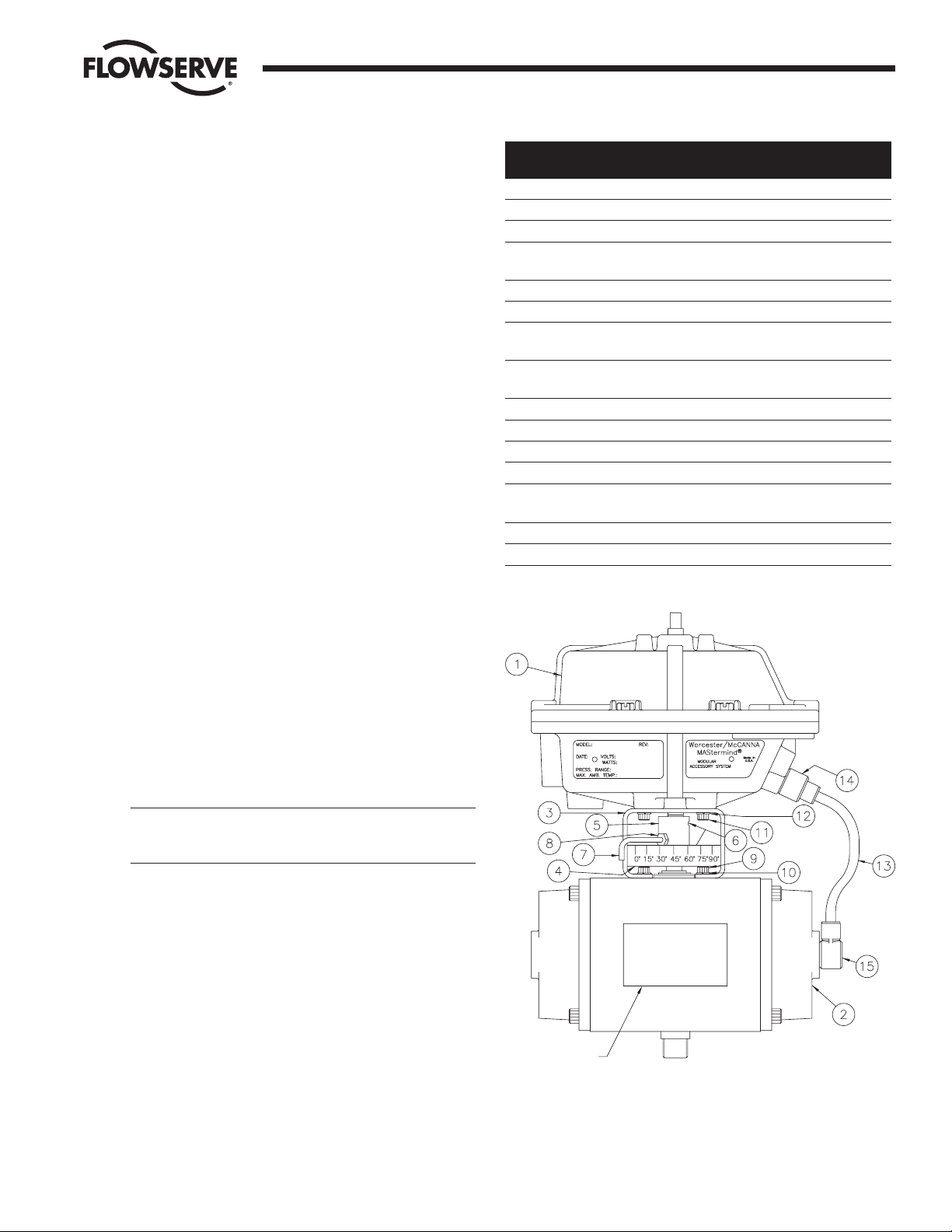
1. Refer to Figure 1. The series 90 is designed to be mounted
in-line with the major axis of the actuator. The air connections
for the series 90 should be on the same end as the air
connections for the actuator. The standard 39 actuator has its
air connections on the right-hand end cap (with the exception
of the line 0539 which has its air connections on the back) as
you face the actuator nameplate. The Series 90 nameplate will
be on the same side as the actuator nameplate.
2. If the actuator is double-acting, rotate the actuator shaft to its
clockwise position. Spring-return actuators will be in this
position already.
3. Place the mounting bracket on the actuator. Brackets to be
used with Series 90 positioner or controller packages may
have an optional indicating scale. This scale can be oriented
on either side of the actuator (depending on customer’s
preference), but normally will be located on the same side as
the actuator nameplate. Secure the mounting bracket with the
four (4) screws and lockwashers supplied in the kit.
4. Place the coupling over the actuator shaft. (Note: For the 05
and 1039 actuators only, shallow slot is placed over the
actuator shaft). Sizes 10-40 couplings have four (4) threaded
holes; two are ¹₄-20 thread for set screws and the other two
are #10-32 (located 45 degrees off the center line of the
coupling). The two #10-32 threaded holes must be on the
same side as the indicator scale (if any) on the bracket. The
size 05 coupling has two (2) ¹₄-20 threaded holes for set
screws only. DO NOT tighten the set screws at this time.
5. If the mounting kit is for a positioner or controller, an optional
indicating arm and locknut for the coupling may be provided.
If so, install this arm into the coupling and secure with the
locknut. The arm will point down and extend outside the
indicating scale mounted on the bracket.
CAUTION: The actuator is in its clockwise position (per step
#2). The indicating arm must be installed to allow rotation
of the actuator shaft in the counter-clockwise direction.
6. Place the Series 90 unit on the bracket while inserting the
shaft into the coupling slot. Be certain the holes in the bracket
and 90 housing are aligned and secure with the four (4) #1032 socket head screws and lockwashers provided.
7. The coupling set screws can be tightened after the actuator
has been cycled 90 degrees.
Item
No. Qty Description
1 1 Series 90 – M.A.S.
2 1 Series 39 Actuator
3 1 Mounting Bracket
4 1 Indicating Scale – Optional
(Positioner/Controller Only)
5 2 Coupling
6 2 Set Screw
7 1 Indicating Arm – Optional
(Positioner/Controller Only)
8 1 Locking Unit – Optional
(Positioner/Controller Only)
9 4 Actuator Mounting Screw
10 4 Actuator Mounting Lockwasher
11 4 M.A.S. Mounting Screw
12 4 M.A.S. Mounting Lockwasher
13 1 ¹₄" O.D. X 31" Tubing
(Cut by User)
14 2 Straight Screw
15 2 Elbow Fitting
07334-F Modular Accessory System (Series 90) 3
Flow Control Division
Worcester Controls
Figure 1
Nameplate
Page 4

4 Modular Accessory System (Series 90) 07334-F
B. Air Connections
1. Series 90 mounting kits contain two (2) elbow “quick”
fittings, two (2) straight “quick” fittings, and one (1) length of
¹⁄₄" O.D. tubing. Single-acting or spring-return assembles will
use one elbow and one straight fitting. Double-acting
assemblies will use two elbow and two straight fittings. The
length of tubing will be cut to suit the assembly (one piece for
spring-return, two pieces for double-acting).
2. Refer to Figure 2. Assemble the elbow fitting(s) to the
actuator. Pipe thread sealant may be used on the threads (do
not allow thread sealant to contaminate the internal air
passages of the M.A.S.). Fluoropolymer tape thread sealant
should not be used.
Actuator Size Port Thread (NPT)
05 – 20 ¹⁄₈"
25 – 40 ¹⁄₄"
3. Refer to Figure 3. Assemble the straight fitting(s) to the
Series 90 housing as shown in Figure 3. The thread sizes are
labeled for reference in the figure. Pipe sealant may be used
on the threads (do not allow thread sealant to contaminate the
internal air passages of the M.A.S.). Fluoropolymer tape
thread sealant should not be used.
4. Cut the tubing provided to as short a length as possible that
will still reach comfortably from the Series 90 unit to the
actuator. On double-acting versions, the tubes run parallel to
each other and do not cross. The operation of the actuator
can be reversed by reversing the location of the tubes at the
actuator. Connect the tubes to their respective actuator and
series 90 ports (ref. Figures 2, 3 and 4).
5. Refer to Figure 4 for a diagram of the Series 90 air
connections in each of its four (4) configurations.
a. Connect the supply air for the actuator (80 psi
nominal/100 psi maximum) to the location labeled
“SUPPLY” in the appropriate sketch.
b. Locations labeled “VENT” may be fitted with a porous
muffler (or other fitting if desired) to reduce exhaust noise.
Air must be allowed to flow freely from these ports. “VENT”
locations must not be plugged under any circumstances.
c. Ports labeled “NOT USED” must remain plugged with the
stainless steel pipe plugs provided.
Flow Control Division
Worcester Controls
Figure 2 – Actuator Fitting Locations Figure 3 – M.A.S. Fitting Locations
Figure 4 – Air Connections for All M.A.S. Configurations
Page 5

07334-F Modular Accessory System (Series 90) 5
III. ASSEMBLY
A. Housing Assembly
The housing consists of the base, cover, shaft, baseplate, and
associated hardware. The housing is assembled as received from
Flowserve. For ease of maintenance, assembly instructions will be
provided here.
1. Cover
CAUTION: Use care to avoid damaging the machined flange
surface of the cover.
a. Apply a light coat of Cindal 2321 lubricant (or other
bearing grease) to the shaft hole.
b. Assemble the captive type cover screws through the
flange holes. The screws must be turned through approx.
¹⁄₄" of thread until they reach the clearance diameter and
remain loose in the cover. Use caution to avoid crossthreading these screws. Refer to Figure 5.
c. Check to see that the shaft seal has been installed as
shown in Figure 6.
CAUTION: When assembling cover to base, be sure
wires are away from any rotating parts and are not
pinched between cover and base flanges.
Relubricate the shaft hole anytime cover is removed
and replaced.
To avoid damaging the cover hole finish and binding the
shaft to cover, check the top of the shaft for burrs or
impact damage before installing or removing cover.
2. Base
CAUTION: Use care to avoid damaging the machined flange
surface of the base.
a. Check to see that the shaft seal and bearing have been
installed as shown in Figure 6.
b. Apply a light coat of bearing lubricant to the shaft hole.
c. Insert the shaft through the shaft hole in the base from
the inside. The shaft fits through this hole with minimal
clearance — care must be taken to avoid damaging the
bearing surfaces or causing the shaft to gall.
d. Place one of the nylon thrust washers onto the shaft end
protruding outside the base. Assemble one of the snap
rings to the shaft in the groove below this thrust washer
(rounded side towards thrust washer – see detail).
e. Place a second nylon thrust washer over the shaft and
into place against the shaft boss on the inside of the
base. Secure the shaft in place with a second snap ring in
the groove adjacent to the second thrust washer (rounded
side towards thrust washer – see detail).
f. Place the third snap ring into the upper groove as shown
in Figure 6.
g. If the base is machined to accept a Breather/Drain fitting
as shown in Figure 7, then the boss on the bottom of the
base near the electrical conduit connection bosses will be
tapped with ³₈" NPT threads. If this boss is tapped, the
Breather/Drain fitting must be installed. The use of
fluoropolymer tape or other thread sealant is
recommended prior to installing this fitting into the boss.
h. Plug the ³₄" NPT conduit connection on the end of the
base temporarily with the threaded plastic plug provided.
This plug will be removed and discarded when the unit is
installed.
i. Plug the (4) ¹₄" NPT and (1) ¹₈" NPT air connection ports
with the stainless steel pipe plugs provided. Thread
sealant is not recommended prior to installing these
plugs. The residue left by a thread sealing compound
could foul the solenoid valve air passages. If a solenoid
valve option is to be installed in the unit, some of these
plugs will not be used – refer to the Solenoid Block
Installation Instructions to determine which plugs can be
left out.
IMPORTANT: If no solenoid is to be used, all of the ports
must be plugged. Refer to Figure 7.
j. The M.A.S. uses a standard O-ring to achieve both
Watertight (TYPE 4) and Explosion-proof – (TYPE 7)
ratings. Refer to Figure 8.
Flow Control Division
Worcester Controls
Figure 5
Figure 6
Page 6

6 Modular Accessory System (Series 90) 07334-F
k. Refer to Figure 9. The baseplate contains one factory-
assembled terminal strip located in the “primary” (side)
location on the baseplate. A second terminal strip is
required with some M.A.S. options, outlined below. The
extra terminal strip will be provided with the appropriate
options. Attach it to the baseplate with four #4 x ³₈" selftapping screws provided in the “secondary” (end)
location.
l. Assemble the baseplate into the base using the four
#6 – 32 screws provided. Use care when tightening these
screws as the baseplate is plastic and could be damaged
if over-tightened.
If options such as Switches, Potentiometer kit, etc. are to
be installed, they can be assembled to the baseplate prior
to installing baseplate into base.
CAUTION: Avoid contacting baseplate with solvents –
damage may result.
Options Requiring
Second Terminal Strip *
Feedback Potentiometers – P, D, 4
Switches – M4, D2
Positioner – All
Controller – All
* Included with option or kit if required.
m. The base is provided with an alignment pin pressed into
the flange that will allow the cover to be assembled in
only one orientation (See Figures 9 and10). Be certain the
cover is correctly positioned prior to tightening bolts, or
damage may result.
n. M.A.S. options are supplied with wiring diagrams that
should be affixed to the inside of the cover as shown in
Figure 10. Note the orientation of the terminal strips on
the wiring diagrams and their location in the cover.
Flow Control Division
Worcester Controls
Figure 7
Figure 8
Figure 10
Figure 9
Page 7

07334-F Modular Accessory System (Series 90) 7
3. Troubleshooting
Problem Possible Cause Solution
Shaft binds Cover not Loosen cover screws
centered and allow cover to
center on shaft.
Retighten cover screws.
Inadequate Remove cover and
lubrication lubricate shaft hole with
bearing grease, such as
Cindol 2321. If excessive
wear or galling is
present, shaft and
affected part of housing.
Flow Control Division
Worcester Controls
Page 8

Flow Control Division
Worcester Controls
Flowserve Corporation has established industry leadership in the design and manufacture of its products. When properly selected, this Flowserve product is designed to perform its intended function
safely during its useful life. However, the purchaser or user of Flowserve products should be aware that Flowserve products might be used in numerous applications under a wide variety of industrial
service conditions. Although Flowserve can (and often does) provide general guidelines, it cannot provide specific data and warnings for all possible applications. The purchaser/user must therefore
assume the ultimate responsibility for the proper sizing and selection, installation, operation, and maintenance of Flowserve products. The purchaser/user should read and understand the Installation
Operation Maintenance (IOM) instructions included with the product, and train its employees and contractors in the safe use of Flowserve products in connection with the specific application.
While the information and specifications contained in this literature are believed to be accurate, they are supplied for informative purposes only and should not be considered certified or as a guarantee of
satisfactory results by reliance thereon. Nothing contained herein is to be construed as a warranty or guarantee, express or implied, regarding any matter with respect to this product. Because Flowserve
is continually improving and upgrading its product design, the specifications, dimensions and information contained herein are subject to change without notice. Should any question arise concerning
these provisions, the purchaser/user should contact Flowserve Corporation at any one of its worldwide operations or offices.
For more information about Flowserve Corporation, contact www.flowserve.com or call USA 1-800-225-6989.
FLOWSERVE CORPORATION
FLOW CONTROL DIVISION
1978 Foreman Drive
Cookeville, Tennessee 38501 USA
Phone: 931 432 4021
Facsimile: 931 432 3105
www.flowserve.com
© 2003 Flowserve Corporation, Irving, Texas, USA. Flowserve and Worcester Controls are registered trademarks of Flowserve Corporation. 07334-F 9/03 Printed in USA
 Loading...