

Overview
ITEM
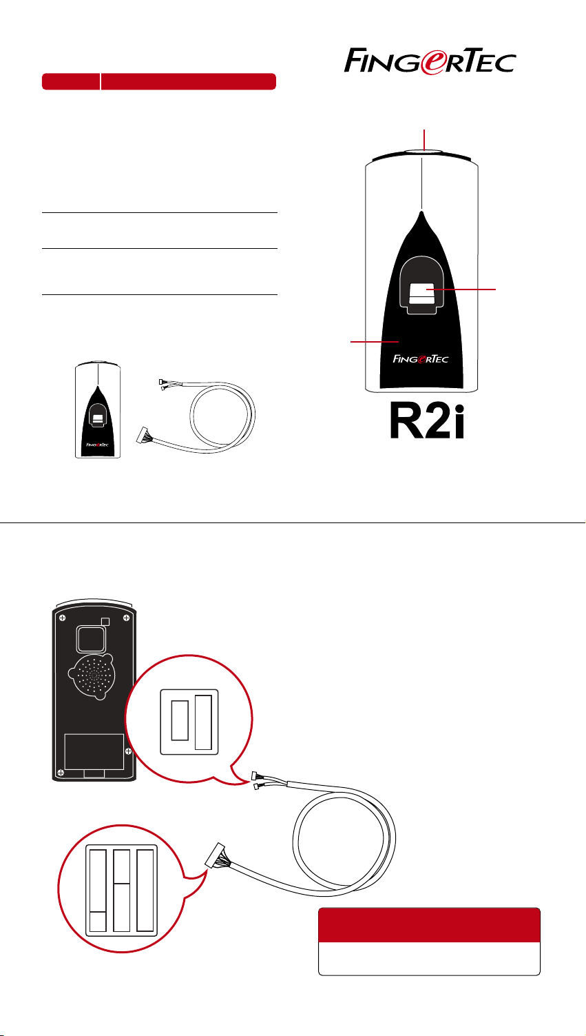
Led Light
Indicator
Fingerprint
Scanner
Card
Induction
Area
WHAT IS IT FOR
Indica ting use rs with the s tatus of terminal an d status of veri fication.
Blue l ight
Terminal is powered on and on standby
to accept fingerprint or card input.
Green light
User i s verified successfull y.
Red li ght
User verification f ailed. Ter minal requests
user t o try again.
Captur ing user ’s fingerprint an d the d ata
will be s ent to master terminal for verification .
Reading and capturing details of cards
and the data will be sent to master terminal for verificatio n. (RFID (Default), MIFARE or HI D)
Led Light Indicator
Fingerprint
Scanner
Package
R2i
FingerTec R2i RS232-USB connection wire
Connection To Master Terminal
.
.
.
.
.
.
.
.
.
.
.
Card
Induction
Area
R2i
Fingerprint & Card Capturing Terminal
USER GUIDE
Precaution Before Installation
The master terminal has to have 11-pin connec tion
port as shown in the photo. FingerTec master terminals that are not having this 11-pin connection port
could not support FingerTec R2i.
Turn off the power of the entire system before initiating the installation of FingerTec R2i to the master
terminal.
FingerTec R2i obtains power from the master terminal, no additional power supply is required for FingerTec R2i.
Back o f R2i Connection Port of R2 i
.
.
.
.
.
.
.
.
.
.
.
.
.
Connec tion Port o f Master Termin al
.
.
.
.
.
.
.
.
.
.
.
.
.
.
.
.
.
.
.
.
.
.
.
FingerTec R2i can only work with
FingerTec R2.
Installation Guide please refer to
http:/ /info.f inge rtec .com /r2i -3
Contact support@fingertec.com for any
technical assistance
w w w . f i n g e r t e c . c o m
 Loading...