


Ingressus IV
Controllers
Centralization of Access Control Devices Made Easy
Installer Guide

CONTENTS
1 • INTRODUCTION 3
The Overview of Hardware 5
The Overview of Installation & Communications 7
• Installations with door lock system
• Connection with PC/Server
• To install Ingressus
2 • TECHNICAL SPECIFICATIONS 9
3 • BEFORE INSTALLATION 10
The Power Supply 10
The Door Locks System 10
The Slave Terminals 12
•
Wiegand Reader
• RS485 Reader
4 • INSTALLATION INSTRUCTIONS & DIAGRAMS 13
Power-up Ingressus 13
Connecting to Wiegand Reader
• k-Kadex, i-Kadex 14
Connecting to RS485 Reader • R2c 15
Connecting to Door Lock System via Wet Contact 17
Connecting to Door Lock System via Dry Contact 18
Connecting to AUX Components 18
Configuration of DIP Switch 19
5 • LED LIGHT INDICATOR 22

3
DIAGRAM I
Slave Reader Credentials Sample Model Connection to Ingressus
RS 485 Fingerprint, card ID R2c RS 485 port
Wiegand Card ID, password i-Kadex, k-Kadex Wiegand port
DIAGRAM II
Controller Door Lock Qty
Ingressus I 2 sets for 1 door
Ingressus II 4 sets for 2 door
Ingress IV 8 sets for 4 door
1 • INTRODUCTION
The FingerTec Ingressus door access controller comes in 3 versions, Ingres-
sus 1 (1 door version), Ingressus II (2 door version) and Ingressus IV (4 door
version). Ingressus provides a computerized central control access control
system to secure the environment. Ingressus can store fingerprints, pass-
word and card ID of every user. It justifies accessibilities of every user ac-
cording to the data/settings configured in it.
The Ingressus connects with slave readers to build a complete access con-
trol system to guard entry-exit of a premise. The slave readers can be either
RS485 readers (reader to capture fingerprints and card ID from users) or Wi-
egand readers (reader to capture card ID and password from users). RS485
reader connects to Ingressus via RS485 network (multi-drop), for example
R2c. Ingressus I supports 2 units of RS485 Reader, while the Ingressus II can
support 4 units. The RS485 network of RS485 Reader shall link to the RS485
port of the Ingressus. Ingressus I supports 2 units of Wiegand Reader while
Ingressus II supports up to 4 units. Each Wiegand Reader, for example i-Ka-
dex and k-Kadex, connects to the Wiegand port of Ingressus (max 4 ports,
Wiegand 1, 2, 3 and 4).
Ingressus I supports up to 2 sets of door locks (1 door); Ingressus II supports
up to 4 sets of door locks (2 doors) and Ingressus IV supports up to 8 sets of
door locks (4 doors).

4
Ingressus can support 2 types of door lock output, either wet contact
or dry contact. For wet contact, Ingressus can output power to the door
lock system. You can supply additional power supply this is suitable with
the door lock system to Ingressus the maximum is 12VDC 3A. For dry
contact, Ingressus outputs relay signal to door lock system. You must
install an independent power supply to the door lock system. Ingres-
sus will only output relay signal to the door lock system to unlock/lock
it. Dry contact is a more secure installation because door lock systems
have their own power supply, it remains working even though Ingressus
is powered down.
Ingressus II and IV can support AUX input and output. You can install
sensors/detectors for example smoke detector as AUX input and alarm
as AUX output. When the smoke sensor triggers, Ingressus will trigger
the alarm to alert all users. You can configure in Ingress software to un-
lock all doors in case of fire or smoke detected. See the technical specifi-
cations to learn the kinds of AUX input/output available.
The Ingressus comes with its management software, Ingress. Ingress
stores a copy of user information and entry-exit records in PC/server.
An administrator can always update user information and restriction of
access to every Ingressus. An administrator can preview and print useful
reports to check entry-exit of each user. Ingress also works as a monitor-
ing station for all connected Ingressus to enhance security levels of the
environment.
Ingressus provides 2 types of communications to Ingress. You can link
up multiple units of Ingressus by using RS485 network or using TCP/IP
(LAN) to a single Ingress. With Ingress, you can now have all entry-exit
control of all users on a server for easy management.
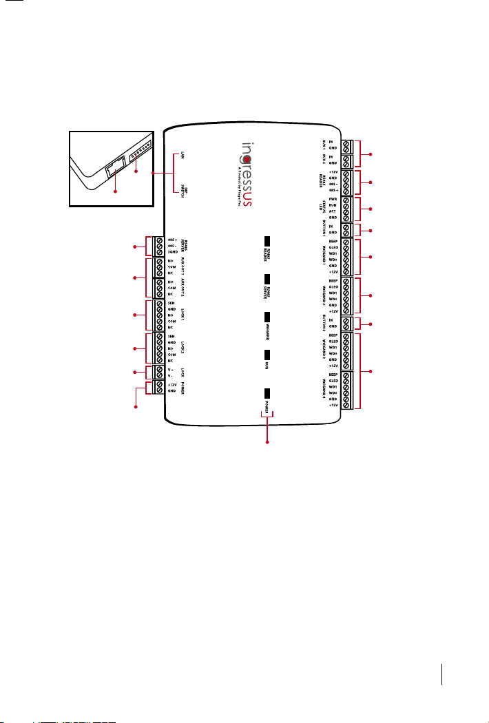
5
* These ports are available in Ingressus II.
LED light indicators
TCP/IP Ports
DIP
switch
RS485 connection
to PC/server
AUX output ports
(max 2 ports)*
Power input to
Ingressus
(Max 12V 3A)
Door lock system
output (door 1)
Door lock system
output (door 2)*
Power input for
door lock system
(Max 12V 3A)
AUX input ports
(Max 2 ports)*
RS485 reader
input ports
Status LED output
ports
Push release button
input ports (Door 1)
26-bit Wiegand
input ports
(Wiegand reader 1)
26-bit Wiegand
input ports
(Wiegand reader 2)
26-bit Wiegand
input ports
(Wiegand reader
3 & 4)*
Push release
button input
ports (Door 2)*
THE OVERVIEW OF HARDWARE
• Ingressus I & II
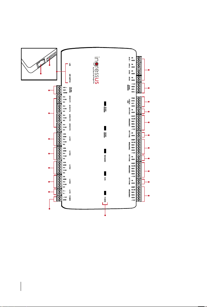
6
LED light indicators
TCP/IP Ports
DIP
switch
RS485 connection
to PC/server
AUX output ports
(max 4 ports)
Power input to
Ingressus
(Max12V 3A)
Door lock system
output (door 1)
Door lock system
output (door 4)
Power input for
door lock system
(Max 12V 3A)
AUX input ports
(Max 4 ports)
RS485 reader
input ports
Status LED output
ports
Push release button
input ports (Door 1)
26-bit Wiegand
input ports
(Wiegand reader 1)
26-bit Wiegand
input port
(Wiegand Reader 3)
26-bit Wiegand
input ports
(Wiegand reader 4)
Push release
button input ports
(Door 4)
Door lock system
output (door 3)
Door lock system
output (door 2)
Push release
button input ports
(Door 3)
26-bit Wiegand
input ports
(Wiegand reader 2)
Push release
button input ports
(Door 2)
• Ingressus IV
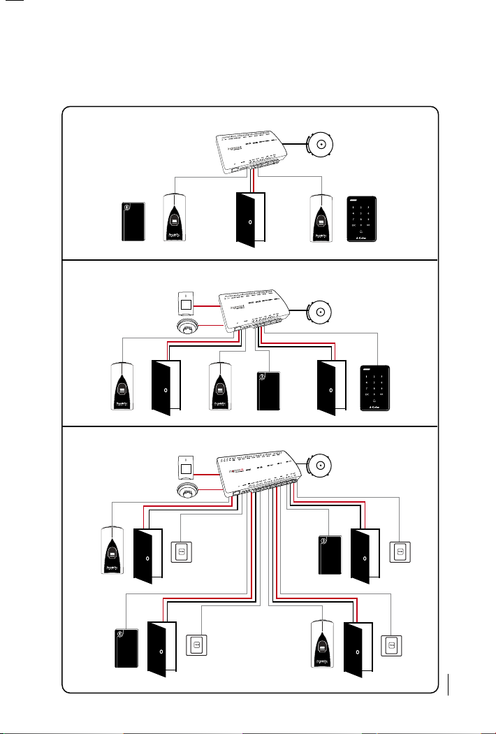
7
THE OVERVIEW OF INSTALLATION & COMMUNICATIONS
The installations with door lock system
• Ingressus I
• Ingressus II
• Ingressus IV
Aux. Relay
Output
Aux. Digital
Output
Aux. Relay
Output
Electric Lock Door Sensor
Aux. Relay
Output
i-Kadex or R2c R2c or k-Kadex
i-Kadex
R2c
R2c
Electric Lock Door Sensor E lectric Lock Door Sensor
R2c R2c
i-Kadex
R2c R2c i-Kadex k-Kadex
Aux. Digital
Output
Electric
Lock
Door
Sensor
Electric
Lock
Door
Sensor
R2c
Push
Button
Push
Button
i-Kadex
R2c i-Kadex
Electric
Lock
Door
Sensor
Push
Button
i-Kadex
i-Kadex
Electric
Lock
Door
Sensor
R2c
Push
Button
R2c
8
WALL
Aluminium frame
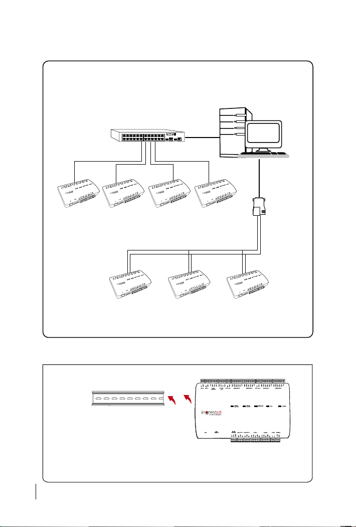
To install Ingressus
1. Install an aluminium frame to a wall or an enclosure.
2. Hook the Ingressus to the aluminium frame.
• TCP/IP - Requires a switch/network hub
• RS485 – Requires a converter
Switch
TCP/IP
TCP/IP
TCP/IP
TCP/IP
Server
RS232/485
Converter
Ingressus Ingressus Ingress us Ingressus
Ingressus Ingressus Ingressus
485+ 485
_
485+ 485
_
485+ 485
_
The connection with PC/Server
 Loading...