


Simple Card Reader for Door Access & Time Attendance System
User Guide

CONTENTS
3 CHAPTER 1 • GETTING STARTED
Viewing the User Guide in the Internet
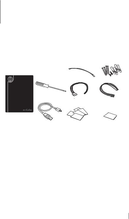
Included Accessories
Included Printed Materials
Activating m-Kadex
Registering m-Kadex
4-5 CHAPTER 2 • BASICS
Introduction to m-Kadex m-Kadex Overview Security Features
Restarting and Resetting m-Kadex
6-13 CHAPTER 3 • CONNECTION – SYNCING M-KADEX
Installation Guide Communication Diagrams
Description of Available Connections Ingress Online Activation Installation and Setup of Ingress Connecting Terminals to Ingress Using USB to Download/Upload Data Communication Key
To Download Attendance Logs Only
To Download User Data and Attendance Logs into USB Flash Disk To Upload User Data from USB Flash Disk to m-Kadex
14-15 CHAPTER 4 • MANAGING USER
Enrolling Administrator Card Registration of Administrator Card Enrolling User Cards
Verifying Card for Attendance or Access Deleting User Card
Deleting Attendance Logs in m-Kadex
Resetting to Default Factory Settings using Administrator Card Resetting to Default Factory Settings without Administrator Card
16 CHAPTER 5 • OTHER RESOURCES
1 • GETTING STARTED
Viewing the User Guide in the Internet
The User Guide is available in the package when you purchase FingerTec m-Kadex. The user guide is also published online at fingertec.com and user.fingertec.com. Choose the language you prefer to view the User Guide.
Included Accessories
|
Power Supply Cable |
A Packet of Bolts |
|
Screwdriver
Door Accessories |
RS232/RS485/ |
Cable |
Wiegand Output Cable |
m-Kadex terminal
USB Extension |
RFID Card (5 pieces) |
MIFARE Card (1 pieces) |
|
*for m-Kadex RFID |
*for m-Kadex MIFARE |
Included Printed Materials
•FingerTec Comprehensive DVD
•Quick Start Guide
•User Enrollment Template Form
•Warranty Card
Activating m-Kadex
Connect all the cables correctly at their specific points and turn on the power supply. M-Kadex terminal does not have its on/off button.
Registering m-Kadex
Make sure that you register your m-Kadex’s warranty with us at www.fingertec.com/ ver2/english/e_main.html#
 CONTENTS 3

2 • BASICS
Introduction to m-Kadex
m-Kadex is a simpler version of Kadex. The terminal is designed without any keypads or LCD. m-Kadex functions similarly like Kadex but management of the terminals have to be done from the software. The m-Kadex can enrol new cards and delete cards at the terminal only if the administrator card is available. Absence of administrator card would not allow any operations to be carried out at the terminal.
m-Kadex Overview
LED
Card
Induction
Area
Item
LED
USB Port
Reset button
Reset
What Is It For
Indicating status of terminal and result of verification
Green – Terminal is in standby mode, terminal has verified card successfully
Red – Terminal has failed to verify card
|
|
Card Induction Area |
Area to read card |
|
|
|
|
|
|
USB Port |
Connecting USB extension for data download into a USB flash disk |
|
|
|
(pen drive) |
|
|
|
|
|
|
Reset button |
Restarting the terminal |
4 |
|
|
|
|
CONTENTS |
|
|
|
|
||
|
|
|
|

Security Features
Security features help protecting the information from m-Kadex from being accessed by unauthorized individual(s).
ADMINISTRATOR CARD
Registration of an administrator card to the system is important to control access into m-Kadex. After registration of the administration card is done, nobody can do enrollment, deletion or reset on m-Kadex without the administration card.
TAMPER SWITCH
m-Kadex comes with a tamper switch located at the rear of the terminal. During installation, the tamper switch is compressed against a wall. Any attempt to dismantle m-Kadex will trigger alarm
Restarting and Resetting m-Kadex
If something isn’t working right, try to restart or reset m-Kadex.
RESTARTING m-Kadex
Use a thin probe to push the reset button hidden at the bottom of the terminal. The terminal will restart by itself and all the memory is retained during this operation.
RESETTING TO DEFAULT FACTORY SETTINGS BY
ADMINISTRATOR CARD
Green LED blinks > Wave Administrator card 5 times at the induction area > The terminal beeps 3 times > Red LED blinks > Wave Administrator card 1 time at the induction area to confirm > Green LED blinks > The terminal beeps continuously for 7 seconds > Green LED blinks
Remarks: All contents of the terminal will be deleted including the contents in administrator card. The IP address of the terminal returns to default 192.168.1.201 after this process. The Terminal ID returns to 1 after this process.
RESETTING TO DEFAULT FACTORY SETTINGS WITHOUT ADMINISTRATOR CARD
Green LED blinks > Detach terminal from a wall > Release security button > Wait for 35 seconds > Push and release the security button 3 times > Terminal would emit a long beep and it will start the terminal
Remarks: All contents of the terminal will be deleted including the contents in administrator card. The IP address of terminal returns to default 192.168.1.201 after this process. The Terminal ID returns to 1 after this process.
 CONTENTS 5

3 • CONNECTION – SYNCING M-KADEX
Installation Guide NOTE The installation guides is for installer reference only
Communication Diagrams
At the rear of every terminal, there are connections available for power, communication and door access. Refer to the following diagrams for the terminals you require.
ACCESS CONNECTION PORT
|
|
|
AL- |
|
|
|
|
AL+ |
|
|
|
|
|
|
|
|
|
NC |
|
|
|
|
|
|
|
|
|
COM |
|
For NC |
|
|
||
NO |
||||
or NO |
|
|||
door |
|
|
|
|
BUT |
||||
lock |
|
|||
system |
|
|
||
GND |
||||
|
|
|
||
|
|
|
|
|
|
|
|
SES |
|
|
|
|
|
|
|
|
|
BELL+ |
|
|
|
|
|
|
|
|
|
BELL- |
|
POWER SUPPLY
PORT
GND
+12V
DC12V
Power Supply
TCP/IP PORT |
RJ45-1 |
|
(Ethernet Connection) |
||
|
||
|
RJ45-2 |
|
- |
RJ45-3 |
|
TCP/IP |
||
|
||
|
RJ45-6 |
J7 |
|
J2 |
|
|
||
|
|
|
||||
|
|
|
||||
AL- |
|
RJ45-1 |
|
|
||
AL+ |
|
RJ45-2 |
|
|
||
NC |
|
RJ45-3 |
|
|
||
COM |
|
RJ45-6 |
|
|
||
NO |
|
J12 |
|
|
||
BUT |
|
WDO |
|
|
||
GND |
|
WD1 |
|
|
||
SES |
|
GND |
|
|
||
BELL+ |
|
RXD |
|
|
||
BELL- |
|
TXD |
|
|
||
GND +12V |
|
|
|
|||
|
GND |
|
|
|||
J1 |
|
|
|
|||
|
485A |
|
|
|||
|
|
|
V3.6 - 09032 |
|||
|
|
|
|
|
||
|
|
|
485B |
|
|
J7 |
|
|
|
|
|||
|
|
|
|
|
|
AL- |
|
|
|
|
|
|
AL+ |
|
|
|
|
|
|
NC |
|
|
|
|
|
|
COM |
|
|
|
|
|
|
NO |
|
|
|
|
|
|
BUT |
|
|
|
|
|
|
GND |
|
|
|
|
|
|
SES |
|
|
|
|
|
|
BELL+ |
|
|
|
|
|
|
BELL- |
|
|
|
|
|
|
GND +12V |
|
|
|
|
|
|
J1 |
|
|
|
|
|
|
|
Back of Terminal
J2
RJ45-1
RJ45-2
RJ45-3
RJ45-6
J12
WDO
WD1
GND
RXD
TXD
GND
485A |
V3.6 - 09032 |
485B |
|
RS232/RS485/WIEGAND CONNECTION PORT
|
WD0 |
|
Wiegand Output |
WD1 |
|
|
GND |
3rd party controller |
|
with 26 bits wiegand |
|
|
|
input |
|
RXD |
|
RS232 |
TXD |
|
|
GND |
RS232 |
|
cable |
|
RS485 |
485A |
|
|
|
485B
1. RS485 Single Connection |
|
485A |
RX+ |
485B |
RX- |
|
RS232/RS485 Data |
|
Converter |
2. RS485 Network Connection |
|
485A |
|
485B |
RX+ |
485A |
RX- |
485B |
RS232/RS485 Data |
Converter |
|
6 
 CONTENTS
 Loading...