


supp ort@ fing erte c.com
3
3
Face Recognition System for
Door Access & Time Attendance
User Guide

CONTENTS
3-4 CHAPTER 1 •
GETTING STARTED
Viewing the User Guide on the Internet
Included Accessories
Included Printed Materials
Installation Tips
Activating Terminal
Registering Warranty
59 CHAPTER 2 • BASICS
Introduction
Overview
The Display of LCD Panel
Main Menu
Touch Keypad
Keyboard
Date/Time
Voice Control
Security Features
Cleaning
Restarting and Resetting
1015 CHAPTER 3 • CONNECTION
SYNCING TERMINALS
Installation
Mount on Wall
Communication Diagrams
Description of Available Connections
Ingress Online Activation
Installation and Setup of Ingress
Connecting Terminals to Ingress
Using USB to Download/Upload Data
Communication Key
1618 CHAPTER 4 •
MANAGING USER
Enrolling Users
Voice/Message
Face Verification
Adding User Information
Deleting User
Access Level/Privilege
1922 CHAPTER 5 • SYSTEM
General Settings
Display Settings
Face Settings
Log Settings
Update
System Information
2324 CHAPTER 6 • DATA
Deleting Transaction Logs
Deleting All Data
25 CHAPTER 7 • USB
Understanding the Need for USB Flash Disk
Type of USB
Downloading Attendance Logs
Downloading User Data
Uploading User Data from USB to Terminal
Uploading User Photo
26 CHAPTER 8 • SHORTCUT KEY
Shortcut Keys in Short
Configuring Shortcut Keys
27 CHAPTER 9 • AUTO TEST
Who should do the Auto Test?
Is the Screen OK?
Checking the Voice Message
Checking the Infrared Camera
Is the Time Accurate?
28 CHAPTER 10 • CALIBRATION
Calibrating Screen Sensitivity to Default Level
29 CHAPTER 11 • BELL
Definition of Schedule Bell
Inserting Day and Time to Trigger Schedule Bell
Determining the Ring Type of Schedule Bell
Adjusting Volume of the Bell
Repetition
State
3032 CHAPTER 12 • ACCESS
Most Commonly Used Access Features
Door Access by Time Control
Individual Access Option
3334 TROUBLESHOOTING
1 • GETTING STARTED
Viewing the User Guide on the Internet
The User Guide is available in the package when you purchase the product.
The User Guide is also published online at http://www.fingertec.com and
http://user.fingertec.com
Choose the language you prefer to view the User Guide in.
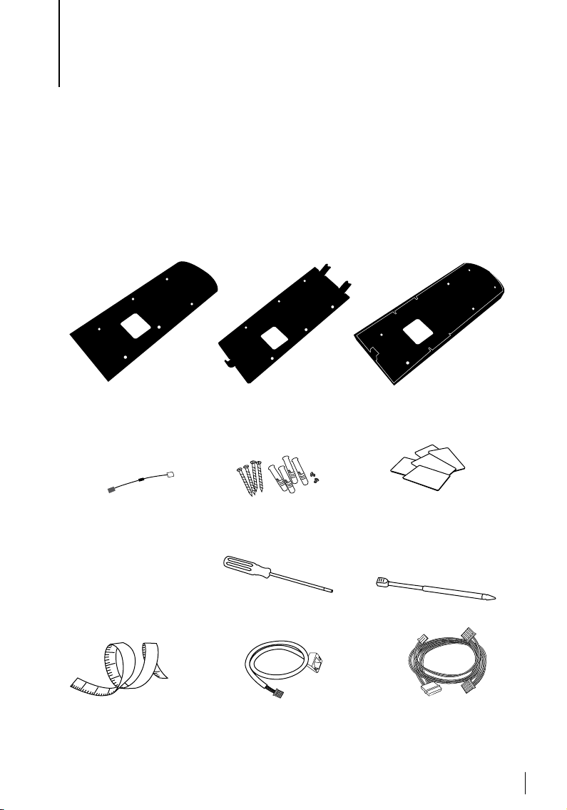
Included Accessories
Rubber Cushion
Place this plate on a wall to
position the terminal firmly
on smooth sur faces, the plate
also acts as current absorber.
Diode
For installation of door lock
system, allowing electrical
current to pass through it in
one direction only; can be
thought of as a check valve.
Diode is not required for installation with AdapTec AC.
1
0
1
1
1
2
3
2
5
1
2
Measurement Tape
Measuring installation
height to achieve optimum
performance for terminal.
Metal Back Plate
Secure this plate on top of the
rubber cushion and hang the
terminal on top of it.
A Packet of Bolts
Use the bolts to mount the back
plate of terminal on the wall.
Screwdriver
T10 screwdriver to open the
back plate of terminal for installation.
Ethernet Converter Cable
To connect the CAT5 to the
terminal and another end to
the LAN connection.
Plastic Back Plate
Use this plate to conceal wires
for a cleaner installation.
RFID Cards (5 pcs)
FingerTec provides extra cards
for RFID (5pcs) and for Mifare
Card, ever y package comes
with only 1 sample card.
Stylus
For easy navigation on touch
screen LCD panel.
Connection Wires
To connect the wires to door
lock, doorbell, RS232 and
RS485, if required.
3
Included Printed Materials
• FingerTec Comprehensive DVD
• Quick Start Guide
• Pamphlet
• User Enrollment Template Form
• Warranty Card
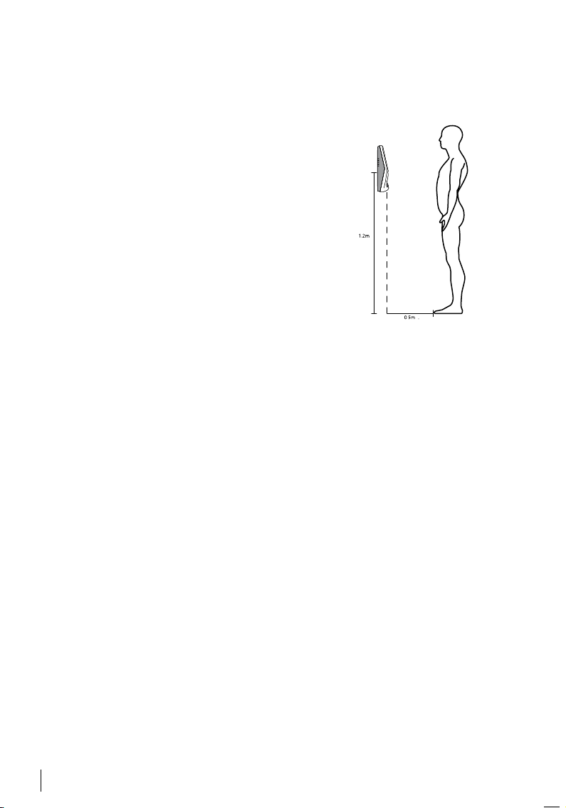
Installation Tips
Best installation location for Face ID 3:
1. Avoid from facing strong sunlight.
2. Must be at least 2 meters away from any strong
light source e.g. ceiling fluorescent light
3. The height must be at least 1.2m from the ground
level to the Face ID 3 camera.
ACTIVATING TERMINAL
Every FingerTec access control model comes bundled with a unique license key.
To start using the terminal with Ingress, you must connect the terminal to Ingress
and perform online activation. Ingress reads the serial number of your terminal
and sends it for verification at the FingerTec server via Internet.
In case you do not have an Internet connection, you would need to do offline
activation. Please send the serial number and models of your terminals to your
local resellers or support@fingertec.com to request for a product key and activation key.
Registering Warranty
Make sure that you register your Face ID 3 warranty with us at
http://www.fingertec.com/ver2/english/e_main.html#
4
2 • BASICS
Introduction
Introducing Face ID 3, the new facial recognition technology product combined
with card technology. Face ID 3 can identify an identity in split seconds without any
contact or hassle. It only requires a user to look at the machine to get verified.
Face ID 3 is loaded with a powerful microprocessor that can process facial authenti
cation method for accurate personal identification and for collection of precise data
for time attendance and door access. In addition, the Face ID 3 terminal accepts card
verification as an added security measure. If you are looking for a contactless, hassle
free biometrics product, choose Face ID 3. With one look you are good to go!
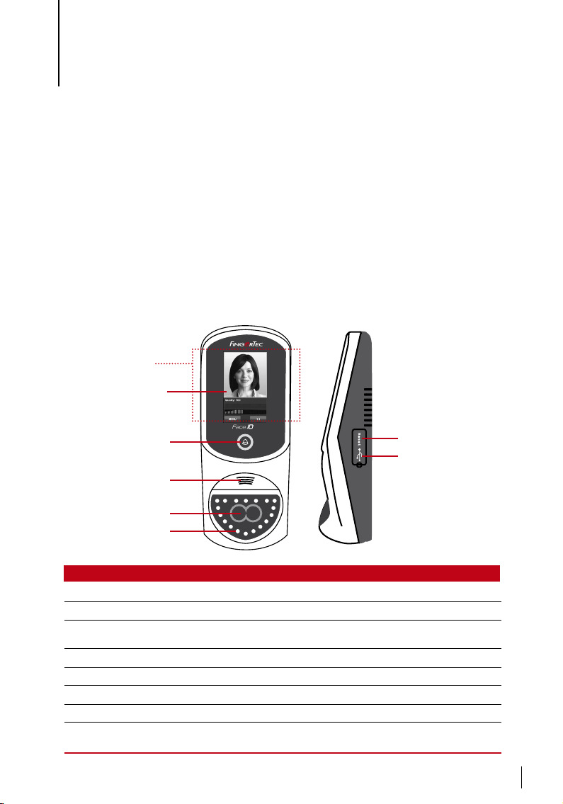
Overview
-
Card induction area
Touch screen LCD
LED indicator and
door bell button
Speaker
Twin face camera
Infrared lights
Item Function
Card induction area Read the card information based on the card system of Face ID 3.
Touch Screen LCD Touch to access the Face ID 3 system to do configuration.
LED Light Indicator Indicate the status of reader. Green indicates standby mode or verifi-
Door Bell button Press to ring the external door bell.
Speaker Emit instructions from Face ID 3.
Twin Face Camera Capture face images in a few directions.
Reset button To restart the machine.
USB Port Connect the USB extension provided here to download/upload data
cation is successful. Red indicates problem or verification has failed.
from/to Face ID 3.
suppo rt@fi ngert ec.com
3
Restart button
USB port
5
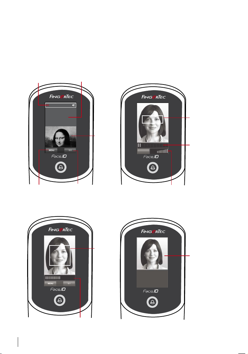
The Display of LCD Panel
Take a closer look at the touch screen LCD panel for some basic and important
information. Press moderately on the LCD when input commands to maintain a
longer lifespan of the terminal. Clean the camera area with a microfiber cloth to
maintain the performance of face scanning.
STANDBY MODE ENROLLMENT MODE
Date/Day
Check-In
sup por
13-11-01
1 6 : 5 3
t@f inge
Thursday
rte c.c om
/4 7
Time
sup por t@f inge rte c.c om
Displays image
of user captured
during enrollment.
Terminal is
in standby
mode,
ready for
scanning.
3
Exit
159
3
Position your eye
to appear in this
area.
Progress bar
to indicate
progress of
facial enrollment.
Menu button to access
into the system.
Tap to view
the keypad.
Status bar to indicate the quality of
the captured image; the higher the
number, the better the image.
VERIFICATION MODE SUCCESSFUL VERIFICATION MODE
sup por t@f inge rte c.c om
Display
image of
user during
enrollment.
Adjust your
position so
142
3
Status bar to indicate the quality of
the captured image; the higher the
number, the better the image.
your face
appears in
this area.
6
sup por t@f inge rte c.c om
User ID: 3
Name:
[16 : 55] Verified.
3
The system
will display
your photo,
user ID and
name after
verifying your
identity.
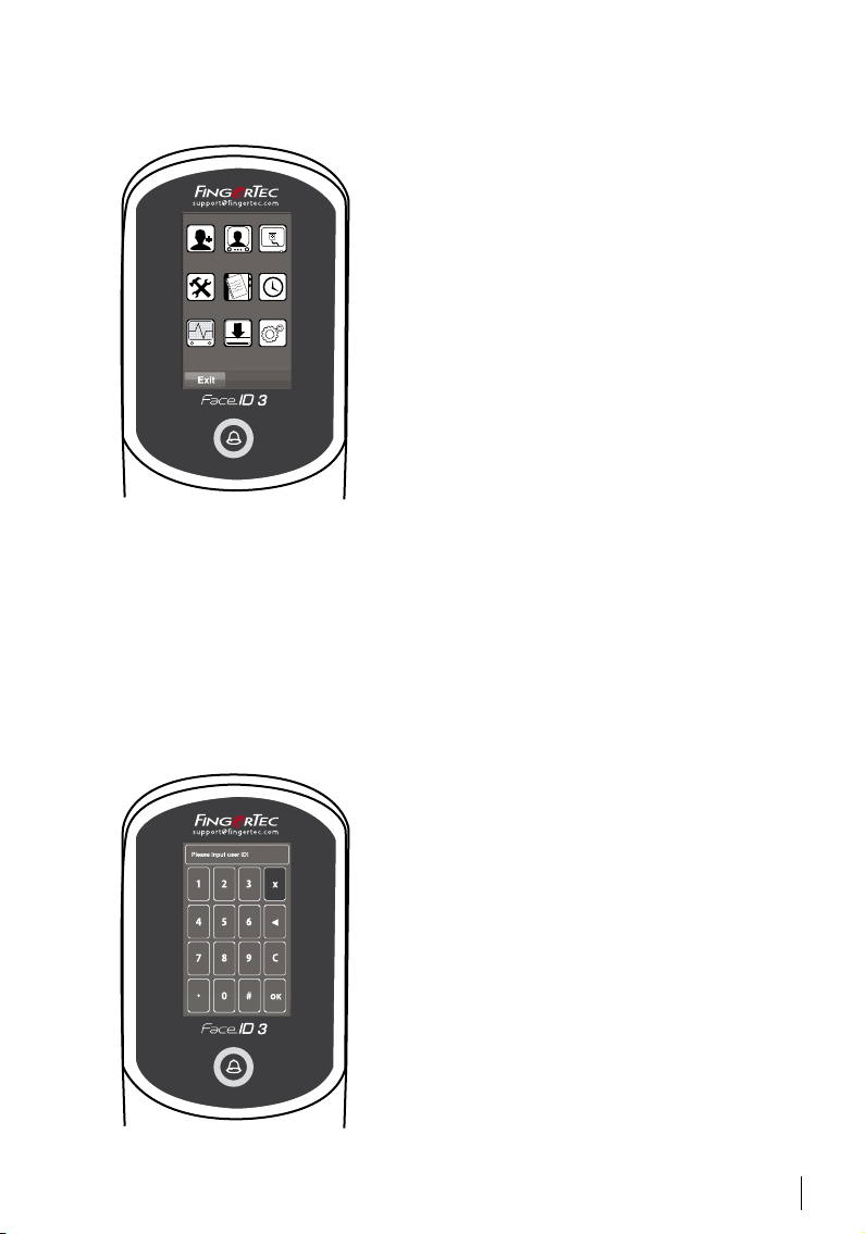
Main Menu
New User
Add new user to the Face ID 3.
User
Enroll, edit, delete, and insert user information from
User icon. The Face ID 3 allows storage of 200 facial
New User User Connection
System Data Date/Time
Auto Test USB Sys Info
Auto Test
Run tests on the Face ID 3 to diagnose the terminal on various aspects.
USB
Transfer data to and from the Face ID 3 using a USB flash disk.
Sys Info
Show basic information of the Face ID 3 and its storage status.
images.
Connection
Setup the Face ID 3 communication with computer
through LAN, RS232 and RS485. Set communication
with a computer for a secure data transfer.
System
Configure the settings of the Face ID 3 including attendance and update settings.
Data
Check user attendance and transaction logs that are
available in the Face ID 3 and perform housekeeping
of the terminal.
Date/Time
Shortcut to set date/time into the Face ID 3.
Touch Keypad
Press 1:1 to view the touch keypad. You can input information into the Face ID 3 through the touch keypad.
It contains numbers from 0-9, face verification mode (1
to 1 or 1 to many), password verification mode, Cancel,
and Backspace buttons.
7
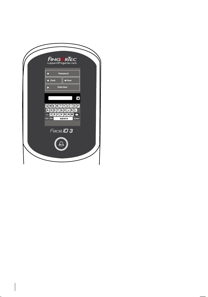
Keyboard
Use the onscreen QWERTY keyboard to type in alphabet and number input into
the Face ID 3.
Type Upper Case
Tap the arrow pointing up on the left
corner of the keyboard to change the
lowercase to upper case.
Type Number
Tap the 123 key to change the keyboard to display numbers.
Return
Tap Enter to return. Tap X on the keyboard top right corner when you are
done using the onscreen keyboard.
Date/Time
The Face ID 3 displays date and time at the home screen. Choose a date and time
format based on your preference. Press Menu > Date/Time > Select value > Save.
You can select the time format to be either the 12-hour format or the 24-hour format.
Voice Control
Voice Control lets you control the level of volume emitted by the Face ID 3.
Turn On/Off – The Face ID 3 lets you to turn on/off the voice based on your prefer
ence.Press Menu > System > General > Voice Prompts > On/Off >Save.
ADJUST VOLUME
The default volume of the Face ID 3 voice is Mid (medium). To sustain the performance of the speaker in the Face ID 3, the volume is recommended to remain at Mid
value. To adjust the volume Press Menu > System > General > Volume > Select Low
| Mid |High
8
-

Security Features
Security features help protect the information in the Face ID 3 from being accessed by others.
ADMIN AFFIRM
Register an administrator into the system by enrolling a face or password to a
user ID. Press Menu > Add User > Privilege: Administrator > Choose enrollment
method > Save.
After enrolling an administrator, the main menu can only be accessed by administrator.
TAMPER SWITCH
The Face ID 3 comes with a tamper switch located at the rear of the terminal. During installation, the tamper switch is compressed against the back plate. Any attempt to dismantle the Face ID 3 will trigger the internal alarm and the LCD panel
will display “System Broken” to notify users.
Cleaning
Please turn off the terminal before cleaning it.
CLEAN TOUCH PANEL
Use a microfiber cloth to clean the Face ID 3. Do not use any liquids, household
cleaners, aerosol spray, solvents, alcohol, ammonia and abrasive solutions to
clean the touch screen panel of the Face ID 3 because it could damage the
panel.
Restarting and Resetting
If something isn’t working right, try restarting or resetting the Face ID 3.
RESTARTING THE TERMINAL
Open the USB port cover to look for the Restart button use a pin, press the button once to restart the terminal.
RESETTING THE TERMINAL
Go to Menu > Data and click on Restore to Factory Settings. Press Yes to confirm.
Resetting of the Face ID 3 will cause all your settings to return to the original
factory settings.
9
3 • CONNECTION – SYNCING TERMINALS
Installation
FingerTec terminals offer several connections for power and communications. To install the Face ID 3, follow the instructions below.
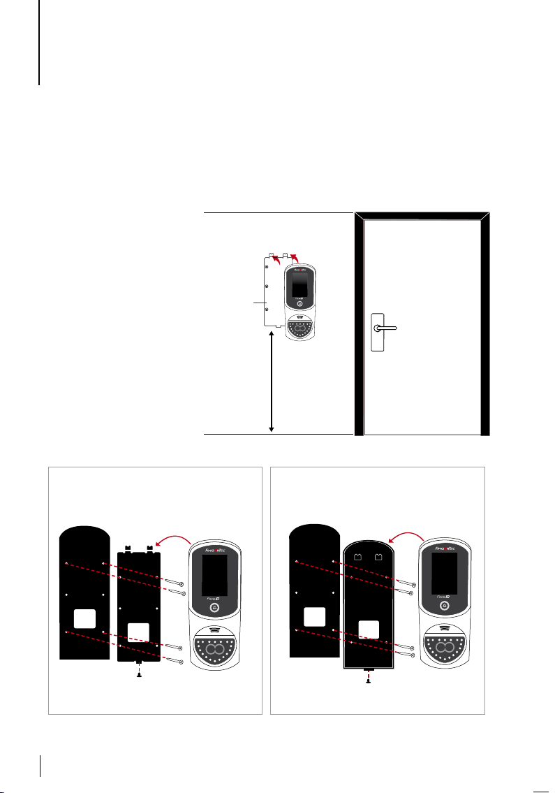
Mount On Wall
Attach the back plate
on to the wall securely
and attach the terminal on to the back
plate when mounting
it on the wall.
FingerTec provides
two kinds of wall
plates with the Face
ID 3. Choose either
one that suits to your
installation requirement.
Back Plate
4 feet / 1.2 meter
(recommended)
rt@fingertec. com
suppo
3
OPTION A OPTION B
Installation using Metal Backplate Installation using Plastic Backplate
support@ fingertec .com
Rubber Cushion
Metal Backplate
10
3
Termin al
Rubber Cushion
Plasti c Backplate
support@ fingertec .com
3
Termin al
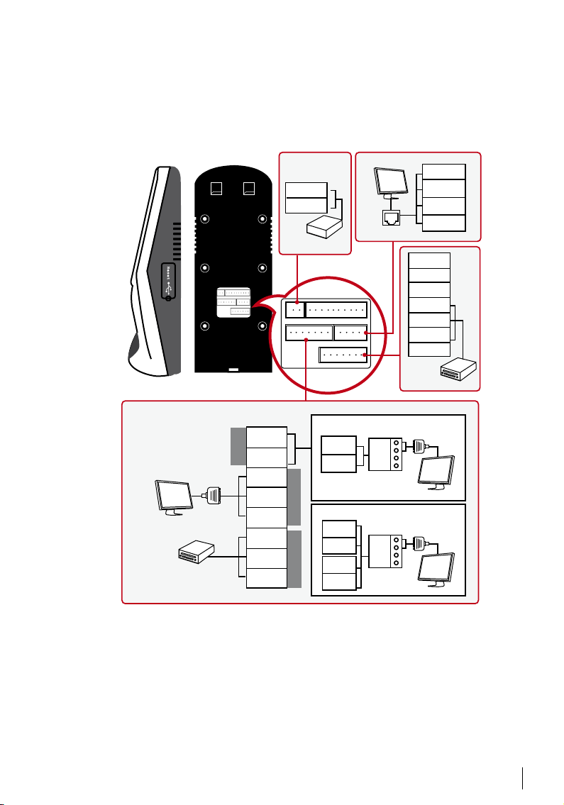
Communication Diagrams
Connection points for power and communication are available at the back of the
terminal. Refer to the following diagrams for the correct installations.
RS232/RS485 SERIAL PORT
RS232
cable
3rd par ty control ler
with 26 bits wieg and
input
485+
485-
TCP/IP PORT
TCP/IP
RX+
RX-
RS232/R S485
Data Co nverter
RJ45-1
RJ45-2
RJ45-3
RJ45-6
BEEP
GLED
RLED
INWD0
INWD1
GND
+12V
3rd par ty
control ler
with 26 bits
wiegand output
POWER
SUPPLY (A)
GND
+12V
DC12V 3A
Power Supply
1. RS48 5 Single C onnection
485-
RS485
485+
GND
TXD
RXD
GND
WD1
WD2
2. RS48 5 Network Connection
485+
485-
485+
Wiegand OUT RS23 2
485-
RX+
RX-
RS232/R S485
Data Co nverter
11
 Loading...