


F24

Appr. nr. B98.01 A - CE 0063 AT 4967
FERROLI F24
INSTALLATION, SERVICE AND USER
INSTRUCTIONS
G.C. NO: 47-267-31
3544015/0 - 07/2002
Gas Combination Boiler for Central Heating
and Hot Water Production, Wall Mounted,
Copper Heat Exchanger, Fan Assisted,
Room Sealed,
Electronic Flame Ignition and Control

FERROLI F24
2
CE MARK
CE mark documents that the Ferroli gas appliances comply with the requirement contained in
European directives applicable to them.
In particular, the appliances comply with the following CEE directives and the technical specifi cations
provided from them:
• Gas appliances directive 90/396
• Effi ciencies directive 92/42
• Low tension directive 73/23 (modifi ed from the 93/68)
• Electromagnetic compatibility directive 89/396 (modifi ed from the 93/68)
IMPORTANT
Your "benchmark" Installation, Commissioning and Service Record Log Book will be enclosed
in your customer information pack.
"This record must be completed and left with the end user"
"All CORGI Registered Installers carry a CORGI ID card and have a registration number. Both
should be recorded in your central heating log book. You can check to the CORGI register
by calling CORGI on 01256 372300".
Ferroli is a member of the Benchmark initiative and fully supports the aims of the programme. Benchmark
has been introduced to improve the standards of installation and commissioning of central heating
systems in the UK and to encourage the regular servicing of all central heating systems to ensure safety
and effi ciency. Please see installation and servicing guidelines.
INDE
1. DESCRIPTION........................................................................................................................................ 3
2. TECHNICAL AND DIMENSIONAL CHARACTERISTICS........................................................................................4
3. INSTALLATION DETAILS........................................................................................................................................9
4. COMMISSIONING AND TESTING.......................................................................................................................26
5. ADJUSTMENT AND GAS CONVERSION............................................................................................................27
6. MAINTENANCE AND CLEANING ......................................................................................................................29
7. REPLACEMENT OF PARTS...................................................................................................................................31
8. FAULT FINDING ...................................................................................................................................................36
9. ELECTRICAL AND FUNCTIONAL SCHEME........................................................................................................43
10. USER INSTRUCTIONS........................................................................................................................................45

FERROLI F24
3
1. DESCRIPTION
1.01 Introduction
The Ferroli F24 is defi ned as a “room sealed” combination boiler, all air required for combustion is taken from
outside the room in which it is installed. It is a new high performance gas fi red heat generator for central heating and
domestic hot water production. A special feature of this boiler is its built-in electronic fl ame ignition and control unit
making burner operation completely automatic and safe. The main components are as follows:
• Copper heat exchanger consisting of three fi nned tubes specifi cally shaped for high effi ciency.
• There are three copper coils inserted in the three heating circuit tubes. These represent the domestic
hot water heat exchang er. Their shape and high exchange surface area enable the full output of the
boiler to be absorbed.
• Ceramic fi bre insulated combustion chamber
• 12 stainless steel bladed burners specifi cally designed for this boiler.
• Fan for discharge of combustion products and intake of combustion air.
• Differential air pressure switch. For safety reasons, this ensures the burner ignites only when the fan is functioning
correctly.
• Hermetically sealed compartment made from corrosion-resistant steel enclosing the above components.
• Combination gas safety valve with modulator, complete with pressure stabiliser.
• Flowmeter giving the domestic hot water circuit precedence over the central heating circuit.
• Pressure relief valve for the central heating circuit set to open at 3 bar.
• Built-in Expansion vessel.
• Variable speed pump.
• Central heating fl ow temperature adjustment thermostat.
• Domestic hot water fl ow temperature adjustment thermostat.
• Central heating limit thermostat.
• Overheat safety thermostat.
• Electronic control unit for automatic fl ame ignition and control.
• Central heating low water pressure cut off switch.
• Domestic hot water fl ow temperature sensor.
• Central heating fl ow temperature sensor.
1.02 Instructions and regulations
Assembly, installation, fi rst start up and maintenance must be carried out by competent persons only, in accordance
with all current technical regulations and directives.
C.O.S.H.H.
Materials used in the manufacture of this appliance are non hazardous and no special precautions are
required when servicing.
Related Documents
This appliance must be installed strictly in accordance with these instructions.
The Gas Safety Regulations (Installations & Use) 1996.
The Local Building Regulations.
The Building Regulations.
The Buildings Standards (Scotland - Consolidated) Regulations.
British Standards Codes of Practice:
B.S. 7593 1992 TREATMENT OF WATER IN DOMESTIC HOT WATER CENTRAL HEATING SYSTEMS
B.S. 5546 1990 INSTALLATION OF HOT WATER SUPPLIES FOR DOMESTIC PURPOSES
B.S. 5440 Part 1 2000 FLUES
B.S. 5440 Part 2 1989 AIR SUPPLY
B.S. 5449 1990 FORCED CIRCULATION HOT WATER SYSTEMS
B.S. 6798 1987 INSTALLATION OF GAS FIRED HOT WATER BOILERS
B.S. 6891 1989 GAS INSTALLATIONS
B.S. 7671 1992 IEE WIRING REGULATIONS
B.S. 4814 1990 SPECIFICATION FOR EXPANSION VESSELS
B.S. 5482 1994 INSTALLATION OF LPG
Model Water Bye Laws
For Northern Ireland the rules in force apply

FERROLI F24
4
Fig. 1
Top view
Distance between connections
178
190 270
Bottom view
272
760
249
98
609536 60 95
460
100
727
114
160100 25 150 25
84
80
80
12070 120 150
110
5
3
4
2
1
2. TECHNICAL AND DIMENSIONAL CHARACTERISTICS
2.01 Technical information
Ferroli F24 boilers are central heating and domestic hot water heat generators and are produced as
standard to function with natural gas or Liquid Petrolium Gas converted appliances.
Key
1 - 3/4" central heating fl ow outlet
2 - 1/2" domestic hot water fl ow outlet
3 - 3/4 “ gas inlet
4 - 1/2" domestic hot water inlet
5 - 3/4" central heating return inlet
6 - Pressure relief outlet

FERROLI F24
5
N.B. - The gas pressures at the burner and gas fl ows during the central heating phase given in the table refer
to nominal boiler output. To reduce this output (where necessary), gas pressure must be reduced until the
required output level is reached (see fi gures 4 and 5).
During domestic hot water production, gas pressures to the burner must correspond to the maximum
output given in table for the type of gas.
Gas pressure must be adjusted during maximum draw-off of domestic hot water.
• Maximum working temperature for central heating fl ow: 85°C
• Maximum temperature of domestic hot water: 55°C, adjustable between 40°C and 55°C.
• Minimum domestic cold water pressure required for 95% heat input:
- Flow restrictor fi tted (standard) - 1,2 bar;
- Flow restrictor removed - 0,5 bar
MODEL
Heat output Heat input
Domestic hot
water output
Boiler water
contents
Domestic hot
water contents
kW kW kW kW kW Litres Litres
Ferroli F24
23,8 9,7 25,8 11,5 23,8 1,5 0,8
MODEL
Connections Expansion vessel
Max. working
pressure
central
heating
circuit
Max.
working
pressure hot
water circuit
12345Capacity
Pre-pressurising
value
Ø Ø Ø Ø Ø Litres bar bar bar
Ferroli F24
3/4” 1/2”
3/4”
1/2” 3/4” 7 1 3 6
MODEL
Main injectors (mm)
Gas flow rates to main burners
for central heating
Gas valve
Ø1/2
G20 - NG G31 -LPG G20 - NG G31 -LPG
ØØ m
3
/h kg/h
Ferroli F24
12x1,30 12x0,77 2,73 2,00 H. V K4105G
MODEL
Gas supply pressures
working
Gas pressure at main burner for central heating
Safety valve
G20 G31
G20 G31
min. m min. m
mbar mbar mbar mbar mbar mbar bar
Ferroli F24
20 37 2,5 11,8 7,8 36,0
MODEL
Domestic hot
water production
with ∆t 30 °C
Domestic hot
water production
with ∆t 35 °C
Max. working
pressure domestic
hot water
Protection
level
Weight
G20 G31
l/min. l/min. mbar mbar kg
Ferroli F24
11,3 9,7 11,8 36,0 IP44 38
Technical Data

FERROLI F24
6
2.03 Boiler water fl ow diagram
OUT
IN
MIN
AIR
IN
AIR
IN
FLUE
OUT
C.H.
OUT
D.H.W.
OUT
GASIND.H.W.
IN
C.H.
IN
Fig. 3
2.02 Boiler main components
Key
5 Room sealed compartment
7 Gas inlet
8 Domestic hot water outlet
9 Domestic hot water inlet
10 Central heating fl ow outlet
11 Central heating return inlet
14 Safety valve
16 Fan
19 Combustion chamber
20 Burner assembly
21 Main injector
22 Burner
26 Combustion chamber insulation
27 Copper heat exchanger for central heating and
domestic hot water
28 Flue collector from heat exchanger
32 Central heating pump
34 Central heating fl ow temperature sensor
36 Automatic air vent valve
42 Domestic hot water fl ow
temperature sensor
Fig. 2
43
16
27
50
19
49
28
5
20
21
26
132
90
91
818222
56
IN
OUT
MIN
RESET
OFF
ON
0
5
1
2
3
4
6
bar
98 63 157 145
°C
°C
62
10 8 784 85 44
136
32
36
114
34
14 42 9 11
43 Air pressure switch
44 Gas valve
49 Safety overheat thermostat
50 Central heating fl ow limit thermostat
56 Expansion vessel
62 Time clock
63 Central heating temperature adjustment
81 Ignition electrode
82 Sensor electrode
84 Primary gas valve solenoid
85 Secondary gas valve solenoid
90* Flue sampling point
91* Air sampling point
98 On/Off/Reset switch
114 Low water pressure cut off switch
132 Flue gas defl ector
136 Flow meter
145 Central heating pressure gauge
157 Domestic hot water temperature adjustment
* For use with fl ue gas analysis equipment

FERROLI F24
7
2.04 Central heating adjustment (not normally required)
To adjust boiler heat input (thus also regulating heat output to the central heating water) simply adjust the main
burner via the electronic control board (fi g. 4 and 5 and see paragraph 5.04 page 29).
The diagrams indicate the variation in heat output to the water as burner working pressure is varied.
Adjusting boiler output to the actual requirements of the central heating system will minimise boiler
cycling thus saving fuel, varying the output has virtually no effect on the efficiency and combustion
characteristics of the boiler.
Diagram of pressures
and outputs with Natural gas
Fig. 4
Fig. 5
Diagram of pressures and outputs
with LPG (Propane)
2
3
4
5
6
7
8
9
10
11
12
13
10 11 12 13 14 15 16 17 18 19 20 21 22 23 24
8 9 10 11 12 13 14 15 16 17 18 19 20 21
kW
kcal/h
x 1000
mbar
14
kW
kcal/h
X 1000
m
b
ar
18 19 20 21 22 23
5
10
15
20
25
30
35
9 1011121314151617
91011121314 18192015 16 178
2.05 Domestic hot water variability characteristics
The temperature of the domestic hot water can
be varied from 40 to 55°C by adjusting the boiler
potentiometer.
Diagram of domestic hot water production
0 345678910111213141516
39
40
45
50
55
60
65
7
8
9
10
11
12
13
14
15
16
17
18
19
20
21
Temperature of domestic hot water intake 15°C
Flow of domestic hot water l/min
Temperature of domestic hot water supply °C
Boiler output exchanged kcal/1000
Fig. 6
FERROLI F24
8
Fig. 8
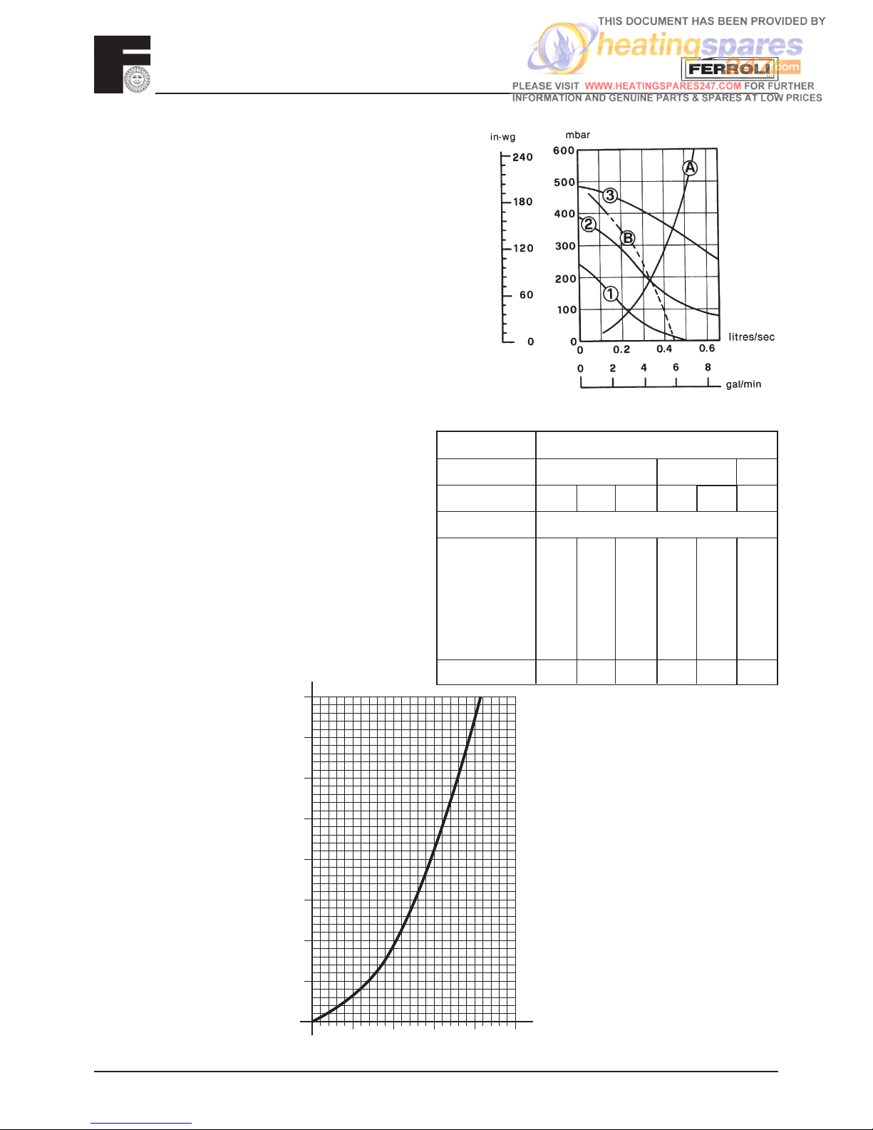
Pressure loss diagram
SIZING OF ADDITIONAL EXPANSION VESSELS:
Deduct from the value given in the table the 8 litre
vessel supplied.
Note:
1. Fill C.H. installation to min. 1.5 bar.
2. Expansion vessel must be fi tted to central heating
return pipe.
3. The standard 7 litre expansion vessel is charged
to 1 bar.
4. The additional expansion vessel should be charged
to 1 bar.
SAFETY VALVE
SETTING (bar)
VESSEL CHARGE
PRESSURE (bar)
INITIAL SYSTEM
PRESSURE (bar)
TOTAL WATER
CONTENT of SYSTEM
3.0
0.5 1.0 1.5
1.0 1.5 2.0 1.5 2.0 2.0
EXPANSION VESSEL VOLUME (litres)
LITRES
25 3.5 6.5 13.7 4.7 10.3 8.3
50 7.0 12.9 27.5 9.5 20.6 16.5
75 10.5 19.4 41.3 14.2 30.9 24.8
100 14.0 25.9 55.1 19.0 41.2 33.1
125 17.5 32.4 68.9 23.7 51.5 41.3
150 21.0 38.8 82.6 28.5 61.8 49.6
175 24.5 45.3 96.4 33.2 72.1 57.9
200 28.0 51.8 110.2 38.0 82.4 66.2
0.140 0.259 0.551 0.190 0.412 0.33
For syst. volumes other than
those given above, mult. the syst.
volume by the factor across
m |h
3
Q
8
7
6
5
4
3
2
1
0
0.5 1.5 2.512
H
mbar x 100
2.06 Pump characteristics
The pump head available for circulating the water is given
in fi g. 7.
N.B. - The pump is factory set at position 3. The pump is a
Grundfos type 15-50 UPS series.
Grundfos Pump per formance graph
Note - Minimum fl ow through boiler heat exchanger at any
time should not fall below 6 litres per minute.
If the total volume of water in the system exceeds 40 litres
an additional expansion vessel must be fi tted to the central
heating return pipe.
Fig. 7
1 2 3 Speed settings
A Boilers pressure drop
B Available pump head C.H.

FERROLI F24
9
3. INSTALLATION DETAILS
Gas Safety (Installation & Use) Regulations: 1996
In the interest of safety, it is the law that all gas appliances are installed by a competent person in accordance
with the above Regulations, Building Regulations/Building Standards Scotland, Codes of Practice, current I.E.E.
Regulations and the byelaws of the Local Water Undertaking. Failure to comply with the Regulations may lead to
prosecution; it is your responsibility to ensure that the law is complied with.
N.B. For Northern Ireland the rules in force apply.
Important - If the boiler is to be fi tted in a timber framed building it should be fi tted in accordance with the Institute of
Gas Engineers document IGE/UP/7. If in doubt advice should be sought from the Local Supplier.
Location of Boiler
The installation of the Ferroli F24 must be on a suitable non-combustible load bearing wall which will provide
an adequate fi xing for the boiler mounting bracket assembly. The location should be in an area where
the water pipes will not be subjected to frost conditions. In siting the combination boiler the following
limitations must be observed:
The combination boiler may be installed in any room or internal space, although particular attention is drawn
to the requirements of the current I.E.E. wiring regulations and in Scotland the electrical provisions of the
building regulations applicable in Scotland, with respect to the installation of the combination boiler in a room
or internal space containing a bath or shower.
Where a room sealed appliance is installed in a room containing a bath or shower any electrical switch
or appliance control utilising mains electricity must be situated so that it cannot be touched by a person
using the bath or shower.
Air Supply
The room or compartment in which the boiler is installed does not require a purpose provided vent when
using the standard concentric fl ue.
Flue System
The boiler allows the fl ue outlet to be taken from the rear of the boiler, from either side or vertically.
A standard fl ue length of 0.75 metres is provided. Alternative lengths of two or three metres can be supplied
(equivalent to wall thicknesses of up to 565, 1815 and 2815mm for rear fl ues, deduct 91mm plus distance from side
wall for side outlet fl ues). It is absolutely essential, to ensure that products of combustion discharging from the
terminal cannot re-enter the building, or enter any adjacent building, through ventilations, windows, doors,
natural air infi ltration or forced ventilation/air conditioning.
Gas Supply
If necessary the local Gas supplier should be consulted, at the installation planning stage, in order to establish
the availability of an adequate supply of gas.
An existing service pipe must not be used without prior consultation with the Local Gas supplier.
A gas meter can only be connected by the Local Gas supplier, or by a Local Gas suppliers Contractor.
Installation pipes should be fi tted in accordance with BS6891-1988.
Appliance inlet working pressure must be 20mbar MINIMUM, for NG and 37 mbar minimum for LPG.
Pipework from the meter to the combination boiler must be of an adequate size.
The boiler requires 2.73m3/h of natural gas, and 2,00 kg/h of LPG.
Do not use pipes of a smaller size than the combination boiler inlet gas connection.
The complete installation must be tested for gas soundness and purged as described in BS6981-1988. All pipework
must be adequately supported. An isolating gas valve is provid ed and should be fi tted on the boiler gas inlet.
Please wait 10 minutes when lighting from cold befor e checking gas rate. Gas pressures should be checked after
the boiler has operated for 10 minutes to reach thermal equilibrium.
Water System
Note - the boiler is designed for sealed systems only and must NOT be used on open vented systems.

FERROLI F24
10
Fig. 9
Central Heating
Detailed recommendations are given in BS6798, BS5449, BS6700 and CP342 Part 2. Pipework not forming part of
the useful heating surface should be insulated to prevent any heat losses or possible freezing (i.e. in roof spaces
or ventilated underfl oor spaces). Drain taps should be positioned at the lowest point of the system in accessible
locations to permit the whole system to be drained down. The drain taps should be in accordance with
BS2879. Copper tubing to BS2871, Part 1 is recommended for water carrying pipework. Pipework in
horizontal runs should have a gradient where possible to facilitate the removal of air. Ensure that the
boiler heat exchanger is not a natural point for air collection. A typical heating system with domestic
hot water circuit is illustrated in fi g. 9.
Important - If thermostatic radiator vales are fi tted a bypass must be fi tted to ensure a minimum fl ow rate through
the boiler of 6 l/min. The bypass should be fi tted as far as possible from the boiler.
Make Up Water
Provision must be made for replacing water lost from the sealed system. Reference should be made to BS6798,
for methods of fi lling and making up sealed systems. There must be no direct connection between the boiler's
central heating system and the mains water supply. The use of mains water to charge and pressurise the system
directly, is conditional upon the Local Water Byelaws. Again any such connection must be disconnected after use.
A typical temporary fi lling loop is shown in fi g. 10.
Domestic Hot Water
Always fi t a scale reducer in "hard water areas" (18 clarke degrees or over)". A 15mm copper connection point
on the boiler for attaching to the main supply is provided. The maximum domestic water pressure for the
inlet supply is 10 bar (145 P.S.I.). If the cold mains supply exceeds 5 bar (72 P.S.I.), a water governor
or pressure reducing valve must be fi tted by the installer into the mains supply in an inconspicuous but
accessible position preferable between 3 and 5 metres (10-16ft) before the appliance. Such a valve must
be approved by the Water Research Council.
Attention - is drawn to the Model Water Byelaws.
Fittings manufactured from duplex (alpha-beta) brass are
not acceptable for underground use and certain water
undertakings will not accept their use above ground.
Ensure all pipework is adequately supported
NOTE: A bypass that will ensure a minimum fl ow rate of
6 l/min. at all all time must be fi tted as far as possible
from the boiler if thermostatic radiator valves are fi tted
thoughout.
Gas
Cold water
Additional expansion
vessel C.H.
Filling
point C.H.
Bypass
Fig. 10
Key
1. Filling point C.H.
2. Temporary connection
3. Cold water supply

FERROLI F24
11
CLEARANCES:
* 600mm minimum clearance for servicing
access
Top clearance only applies to 100Ø concentric
fl ue system
460 5 min.5 min.
100 min.900
200 min.
272 50 mm
600* min.
760
Fig. 11
Terminal Position
Fig. 12
P
D, E
Q
Q
l
B
C
A
G
F
L
J
H
H
K
N
N
MM
Q
Directly below an opening, air brick, (0-7 kW)
opening windows, etc. (>7-14 kW)
(>14-32 kW)
(>32-70 kW)
Above an opening, air brick, (0-7 kW)
opening windows, etc. (>7-14 kW)
(>14-32 kW)
(>32-70 kW)
Horizontally to an opening, air brick, (0-7 kW)
opening windows, etc. (>7-14 kW)
(>14-32 kW)
(>32-70 kW)
Below gutters, soil pipes or drain pipes
Below eaves
Below balconies or car port roof
From a vertical drain pipe or soil pipe
From an internal or external corner
Above ground roof or balcony level
From a surface facing the terminal
(also see 6.1.2)
From a terminal facing the terminal
From an opening in the car port ( e.g. door,
window) into the dwelling
Vertically from a terminal on the same wall
Horizontally from a terminal on the same wall
From the wall on which the terminal is mounted
From a vertical structure on the roof
Above intersection with roof
Dimensions Terminal position
(kW input expressed in net)
Balanced flues room
sealed
Open flues
Natural
draught
Natural
draught
Fanned
draught
Fanned
draught
A
a
300 mm
600 mm
1500 mm
2000 mm
300 mm Not allowed 300 mm
B
a
300 mm
300 mm
300 mm
600 mm
300 mm Not allowed 300 mm
C
a
300 mm
400 mm
600 mm
600 mm
300 mm Not allowed 300 mm
D 300 mm 75 mm Not allowed 75 mm
E 300 mm 200 mm Not allowed 200 mm
F 600 mm 200 mm Not allowed 200 mm
G 300 mm 150 mmbNot allowed 150 mm
H 600 mm 300 mm Not allowed 200 mm
I 300 mm 300 mm Not allowed 300 mm
J 600 mm 600 mm N/A 600 mm
K 600 mm 1200 mm N/A 1200 mm
L 1200 mm 1200 mm N/A 1200 mm
M 1500 mm 1500 mm N/A 1500 mm
N 300 mm 300 mm N/A 300 mm
O N/A N/A N/A 50 mm
P N/A N/A See Table 2
and Fig. 6b
N/A
Q N/A N/A See Table 2
and Fig. 4
150 mm
NOTE N/A = Not applicable
a
In addition, the terminal should not be nearer than 150 mm (fanned draucht) or 300 mm (natural draught) to an opening in the building fabric formed for the purpose of accommodating
a built-in element such as a window frame, (see Figure C2). Separation distances are linked to the rated heat inputs as shown.
b
This dimension may be reduced to 75 mm for appliances of up to 5 kW heat input.
Minimum dimensions of fl ue terminal positions
FERROLI F24
12
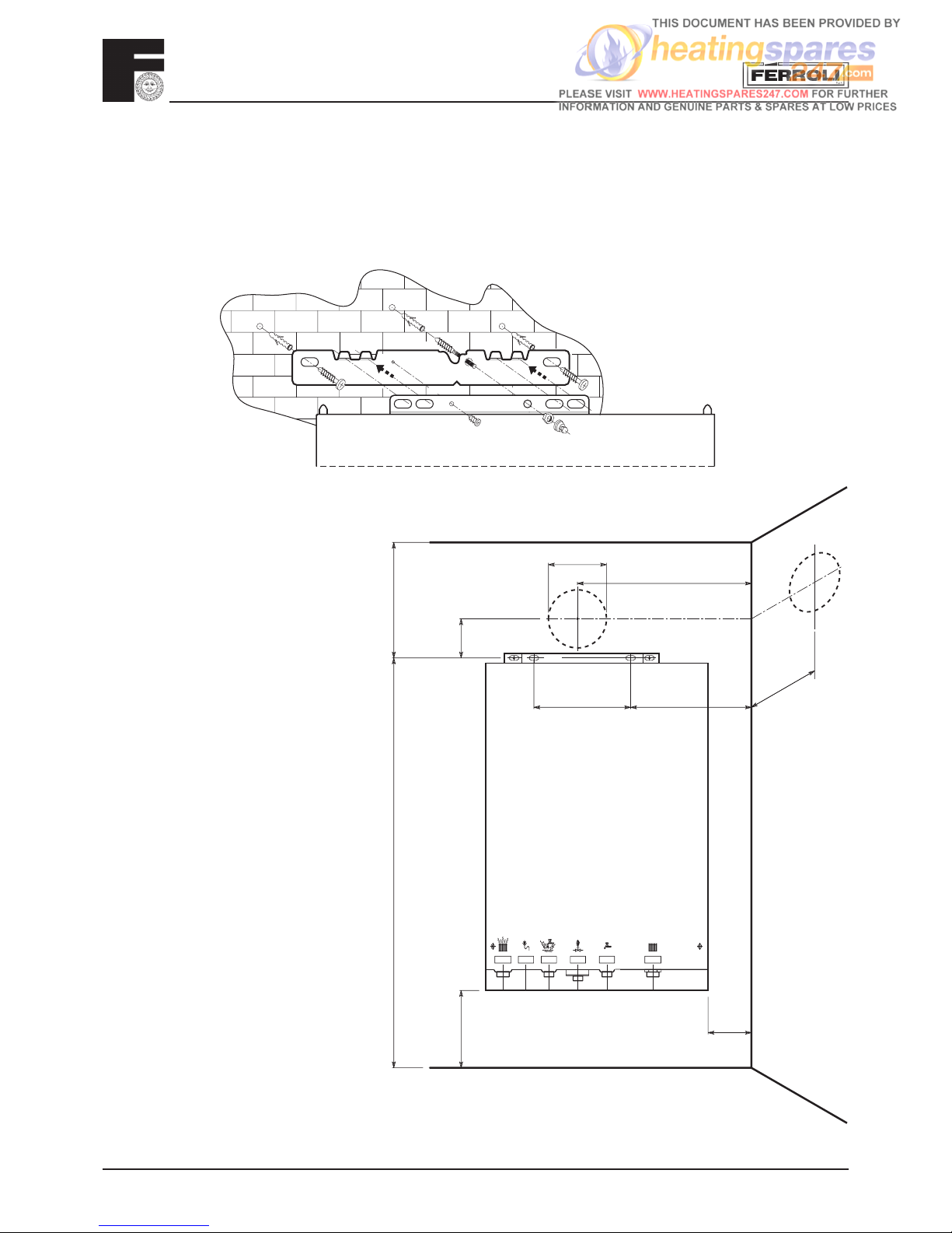
1. CH fl ow
2. Safety Valve
3. Domestic hot water outlet
4. Gas supply
5. Domestic hot water inlet
6. CH return
Ø3/4" Ø1/2" Ø1/2" Ø1/2" Ø1/2" Ø3/4"
200
Ø118
150 min
65
5 min
183 min
200 min
970 min
269
110
12345 6
3.01 Drilling Template (Top Flue Application)
Select suitable mounting position for boiler, using the template mark fl ue outlet and boiler mounting points. Drill
two 10mm holes 70mm deep to accept the wall plugs. Fit standard wall plugs on the left and right side and the special
wall plug in the middle (fi g. 13a). Fix the wall bracket to the wall using standard lock nut (M8) on both sides. Mount
the boiler on the wall bracket and fi x using the special antitheft nut (M8) as described in the fi g. 13a. Using a core
drill cut a 118mm diameter hole for the fl ue.
Fig. 13a
Fig. 13b

FERROLI F24
13
3.02 Restrictor
For boiler operation, the restrictor supplied with the unit must be mounted following the instructions below.
Determine the correct size of fl ue restrictor required. Before inserting the fl ue gas duct in the boiler, check that
the restrictor fi tted is correct and that it is correctly positioned (see fi g. 14).
Holes Ø : 45 47 50
Ø
Fig. 14
CHOICE OF RESTRICTOR:
RESTRICTOR FOR TWO PIPE SYSTEM
Total flow resistance
of flue system
Use
restrictor
size
minimum maximum mm
0 m 13 m 45
13 m 23 m 47
23 m 38 m 50
38 m 48 m No restrictor
• With concentric systems:
- Choose correct restrictor from table below.
• With 2 pipe system:
- Calculate the total fl ow resistance of the air and
fl ue pipes in metres (cap. 3.04.2)
- utilise the table shown below to choose the more
suitable restrictor for the fl ow resistance calculated
RESTRICTOR FOR CONCENTRIC SYSTEM
Flue lenght up to:
Use
restrictor
size
Ccncentric
60 / 100
1 bend + 1 meter 50 mm
1 bend + 3 meters No restrictor
Ccncentric
80 / 125
1 bend + 3 meters 45 mm
1 bend + 4 meters 50 mm
1 bend + 5 meters No restrictor
N.B.: the diameter of the hole is
stamped on the restrictor
No restrictor is required for
back outlet fl ue

FERROLI F24
14
3.03 Top Outlet Concentric Flue Connection
3.03.1 Vertical concentric connection
Fig. 16
A vertical connector can be supplied for vertical
discharge with concentric pipes.
The simple mounting and use of double lip gaskets
at the joints makes this an extremely easy and safe
option.
For fl ue length up to 1 m long the 50 mmØ restrictor is
required. Longer than this no restrictor is required.
Fig. 15
Concentric
Vertical
Connector
3.03.2 Horizontal concentric connection
A 90° bend (fi g. 16) is supplied for the horizontal connection of air and fl ue gas pipes. This can be oriented
towards the chosen wall in degrees of 45°.
Telescopic
DS
L
125
70
50*
30
95
80
80
-3 mm/m
Ø60 Ø80
70 min.
* = between 10 e 60 mm
190 270
L = S + D + 255

FERROLI F24
15
Fig. 17
Notes on concentric horizontal installation
To locate the centre of the hole for passing the
pipes through the wall, refer to fi g. 13b. Bear in
mind that the two concentric pipes must slope
downwards away from the boiler at a rate of
about 3 mm/m to avoid rainwater entering the
boiler. The concentric pipes making up the air
- fl ue gas duct must be sealed with the gasket
where they join the boiler (fi g. 17). Outside, the
pipes should protrude from the wall between 10
and 60 mm (fi g. 17).
3.03.3 Maximum concentric fl ue length
First table below shows the maximum fl ue lengths available for boilers with concentric systems.
For correct calculation remember to include the reduction for bends on second table. Please refer to
3.02 for use of restrictor.
Maximum flue lenght permissible
100 mm concentric
125 mm concentric
Vertical Horizontal* Vertical Horizontal*
Ferroli F24
m4m3m5m5
Reduction for bend
100 mm concentric bend 90° 1 m
100 mm concentric bend 45° 0,5 m
125 mm concentric bend 90° 0,5 m
125 mm concentric bend 45° 0,25 m
*For horizontal Flueing the reduction for appliance bend or turret are already included.
max. 3 m
concentric
100/60
max. 4 m
concentric
100/60
Fig. 18a
Fig. 18b
Between
10-60 mm
 Loading...