

Page 1

FANUC Series 30*-MODEL A
FANUC Series 31*-MODEL A
FANUC Series 32*-MODEL A
For Machining Center System
OPERATOR'S MANUAL
B-63944EN-2/04
Page 2

• No part of this manual may be reproduced in any form.
• All specifications and designs are subject to change without notice.
The products in this manual are controlled based on Japan’s “Foreign Exchange and
Foreign Trade Law”. The export of Series 30i/300i/300is-MODEL A, Series
31i/310i/310is-MODEL A5 from Japan is subject to an export license by the government of
Japan. Other models in this manual may also be subject to export controls.
Further, re-export to another country may be subject to the license of the government of
the country from where the product is re-exported. Furthermore, the product may also be
controlled by re-export regulations of the United States government.
Should you wish to export or re-export these products, please contact FANUC for advice.
In this manual we have tried as much as possible to describe all the various matters.
However, we cannot describe all the matters which must not be done, or which cannot be
done, because there are so many possibilities.
Therefore, matters which are not especially described as possible in this manual should be
regarded as ”impossible”.
Page 3

CHANGE IN CNC MODEL NAMES
CHANGE IN CNC MODEL NAMES
The model names of the following CNCs described in this manual have been changed from those shown
in lower lines to those shown in upper lines in fields of the following table. The model names were
changed, but their specifications remain unchanged. Keep the following in mind when using these
models.
• Replace the old model names in this manual with the corresponding new model names.
• Replace the old model names indicated by the machines with the corresponding new model names.
Table 1 CNC Model Names
Model name Abbreviation
FANUC Series 30i-MODEL A
(Old model name : FANUC Series 300i-MODEL A)
FANUC Series 30i-MODEL A
(Old model name : FANUC Series 300is-MODEL A)
FANUC Series 31i-MODEL A
(Old model name : FANUC Series 310i-MODEL A)
FANUC Series 31i-MODEL A5
(Old model name : FANUC Series 310i-MODEL A5)
FANUC Series 31i-MODEL A
(Old model name : FANUC Series 310is-MODEL A)
FANUC Series 31i-MODEL A5
(Old model name : FANUC Series 310is-MODEL A5)
FANUC Series 32i-MODEL A
(Old model name : FANUC Series 320i-MODEL A)
FANUC Series 32i-MODEL A
(Old model name : FANUC Series 320is-MODEL A)
30i –A
(300i–A)
30i –A
(300is–A)
31i –A
(310i–A)
31i –A5
(310i–A5)
31i –A
(310is–A)
31i –A5
(310is–A5)
32i –A
(320i–A)
32i –A
(320is–A)
Series 30i
(Series 300i)
Series 30i
(Series 300is)
Series 31i
(Series 310i)
Series 31i
(Series 310is)
Series 32i
(Series 320i)
Series 32i
(Series 320is)
Page 4

Page 5

B-63944EN-2/04 SAFETY PRECAUTIONS
SAFETY PRECAUTIONS
This section describes the safety precautions related to the use of CNC units.
It is essential that these precautions be observed by users to ensure the safe operation of machines
equipped with a CNC unit (all descriptions in this section assume this configuration). Note that some
precautions are related only to specific functions, and thus may not be applicable to certain CNC units.
Users must also observe the safety precautions related to the machine, as described in the relevant manual
supplied by the machine tool builder. Before attempting to operate the machine or create a program to
control the operation of the machine, the operator must become fully familiar with the contents of this
manual and relevant manual supplied by the machine tool builder.
CONTENTS
DEFINITION OF WARNING, CAUTION, AND NOTE.........................................................................s-1
GENERAL WARNINGS AND CAUTIONS............................................................................................s-2
WARNINGS AND CAUTIONS RELATED TO PROGRAMMING.......................................................s-3
WARNINGS AND CAUTIONS RELATED TO HANDLING ................................................................s-5
WARNINGS RELATED TO DAILY MAINTENANCE .........................................................................s-7
DEFINITION OF WARNING, CAUTION, AND NOTE
This manual includes safety precautions for protecting the user and preventing damage to the machine.
Precautions are classified into Warning and Caution according to their bearing on safety. Also,
supplementary information is described as a Note. Read the Warning, Caution, and Note thoroughly
before attempting to use the machine.
WARNING
Applied when there is a danger of the user being injured or when there is a
danger of both the user being injured and the equipment being damaged if the
approved procedure is not observed.
CAUTION
Applied when there is a danger of the equipment being damaged, if the
approved procedure is not observed.
NOTE
The Note is used to indicate supplementary information other than Warning and
Caution.
• Read this manual carefully, and store it in a safe place.
s-1
Page 6

SAFETY PRECAUTIONS B-63944EN-2/04
GENERAL WARNINGS AND CAUTIONS
WARNING
1 Never attempt to machine a workpiece without first checking the operation of the
machine. Before starting a production run, ensure that the machine is operating
correctly by performing a trial run using, for example, the single block, feedrate
override, or machine lock function or by operating the machine with neither a tool
nor workpiece mounted. Failure to confirm the correct operation of the machine
may result in the machine behaving unexpectedly, possibly causing damage to
the workpiece and/or machine itself, or injury to the user.
2 Before operating the machine, thoroughly check the entered data.
Operating the machine with incorrectly specified data may result in the machine
behaving unexpectedly, possibly causing damage to the workpiece and/or
machine itself, or injury to the user.
3 Ensure that the specified feedrate is appropriate for the intended operation.
Generally, for each machine, there is a maximum allowable feedrate.
The appropriate feedrate varies with the intended operation. Refer to the manual
provided with the machine to determine the maximum allowable feedrate.
If a machine is run at other than the correct speed, it may behave unexpectedly,
possibly causing damage to the workpiece and/or machine itself, or injury to the
user.
4 When using a tool compensation function, thoroughly check the direction and
amount of compensation.
Operating the machine with incorrectly specified data may result in the machine
behaving unexpectedly, possibly causing damage to the workpiece and/or
machine itself, or injury to the user.
5 The parameters for the CNC and PMC are factory-set. Usually, there is not need
to change them. When, however, there is not alternative other than to change a
parameter, ensure that you fully understand the function of the parameter before
making any change.
Failure to set a parameter correctly may result in the machine behaving
unexpectedly, possibly causing damage to the workpiece and/or machine itself,
or injury to the user.
6 Immediately after switching on the power, do not touch any of the keys on the
MDI panel until the position display or alarm screen appears on the CNC unit.
Some of the keys on the MDI panel are dedicated to maintenance or other
special operations. Pressing any of these keys may place the CNC unit in other
than its normal state. Starting the machine in this state may cause it to behave
unexpectedly.
7 The OPERATOR’S MANUAL and programming manual supplied with a CNC
unit provide an overall description of the machine's functions, including any
optional functions. Note that the optional functions will vary from one machine
model to another. Therefore, some functions described in the manuals may not
actually be available for a particular model. Check the specification of the
machine if in doubt.
8 Some functions may have been implemented at the request of the machine-tool
builder. When using such functions, refer to the manual supplied by the
machine-tool builder for details of their use and any related cautions.
s-2
Page 7

B-63944EN-2/04 SAFETY PRECAUTIONS
CAUTION
The liquid-crystal display is manufactured with very precise fabrication
technology. Some pixels may not be turned on or may remain on. This
phenomenon is a common attribute of LCDs and is not a defect.
NOTE
Programs, parameters, and macro variables are stored in nonvolatile memory in
the CNC unit. Usually, they are retained even if the power is turned off.
Such data may be deleted inadvertently, however, or it may prove necessary to
delete all data from nonvolatile memory as part of error recovery.
To guard against the occurrence of the above, and assure quick restoration of
deleted data, backup all vital data, and keep the backup copy in a safe place.
WARNINGS AND CAUTIONS RELATED TO PROGRAMMING
This section covers the major safety precautions related to programming. Before attempting to perform
programming, read the supplied OPERATOR’S MANUAL carefully such that you are fully familiar with
their contents.
WARNING
1
Coordinate system setting
If a coordinate system is established incorrectly, the machine may behave
unexpectedly as a result of the program issuing an otherwise valid move
command. Such an unexpected operation may damage the tool, the machine
itself, the workpiece, or cause injury to the user.
2
Positioning by nonlinear interpolation
When performing positioning by nonlinear interpolation (positioning by nonlinear
movement between the start and end points), the tool path must be carefully
confirmed before performing programming. Positioning involves rapid traverse. If
the tool collides with the workpiece, it may damage the tool, the machine itself,
the workpiece, or cause injury to the user.
3
Function involving a rotation axis
When programming polar coordinate interpolation or normal-direction
(perpendicular) control, pay careful attention to the speed of the rotation axis.
Incorrect programming may result in the rotation axis speed becoming
excessively high, such that centrifugal force causes the chuck to lose its grip on
the workpiece if the latter is not mounted securely. Such mishap is likely to
damage the tool, the machine itself, the workpiece, or cause injury to the user.
4
Inch/metric conversion
Switching between inch and metric inputs does not convert the measurement
units of data such as the workpiece origin offset, parameter, and current
position. Before starting the machine, therefore, determine which measurement
units are being used. Attempting to perform an operation with invalid data
specified may damage the tool, the machine itself, the workpiece, or cause injury
to the user.
s-3
Page 8

SAFETY PRECAUTIONS B-63944EN-2/04
WARNING
5
Constant surface speed control
When an axis subject to constant surface speed control approaches the origin of
the workpiece coordinate system, the spindle speed may become excessively
high. Therefore, it is necessary to specify a maximum allowable speed.
Specifying the maximum allowable speed incorrectly may damage the tool, the
machine itself, the workpiece, or cause injury to the user.
6
Stroke check
After switching on the power, perform a manual reference position return as
required. Stroke check is not possible before manual reference position return is
performed. Note that when stroke check is disabled, an alarm is not issued even
if a stroke limit is exceeded, possibly damaging the tool, the machine itself, the
workpiece, or causing injury to the user.
7
Tool post interference check
A tool post interference check is performed based on the tool data specified
during automatic operation. If the tool specification does not match the tool
actually being used, the interference check cannot be made correctly, possibly
damaging the tool or the machine itself, or causing injury to the user. After
switching on the power, or after selecting a tool post manually, always start
automatic operation and specify the tool number of the tool to be used.
8
Absolute/incremental mode
If a program created with absolute values is run in incremental mode, or vice
versa, the machine may behave unexpectedly.
9
Plane selection
If an incorrect plane is specified for circular interpolation, helical interpolation, or
a canned cycle, the machine may behave unexpectedly. Refer to the
descriptions of the respective functions for details.
10
Torque limit skip
Before attempting a torque limit skip, apply the torque limit. If a torque limit skip
is specified without the torque limit actually being applied, a move command will
be executed without performing a skip.
11
Programmable mirror image
Note that programmed operations vary considerably when a programmable
mirror image is enabled.
12
Compensation function
If a command based on the machine coordinate system or a reference position
return command is issued in compensation function mode, compensation is
temporarily canceled, resulting in the unexpected behavior of the machine.
Before issuing any of the above commands, therefore, always cancel
compensation function mode.
s-4
Page 9

B-63944EN-2/04 SAFETY PRECAUTIONS
WARNINGS AND CAUTIONS RELATED TO HANDLING
This section presents safety precautions related to the handling of machine tools. Before attempting to
operate your machine, read the supplied OPERATOR’S MANUAL carefully, such that you are fully
familiar with their contents.
WARNING
1
Manual operation
When operating the machine manually, determine the current position of the tool
and workpiece, and ensure that the movement axis, direction, and feedrate have
been specified correctly. Incorrect operation of the machine may damage the
tool, the machine itself, the workpiece, or cause injury to the operator.
2
Manual reference position return
After switching on the power, perform manual reference position return as
required.
If the machine is operated without first performing manual reference position
return, it may behave unexpectedly. Stroke check is not possible before manual
reference position return is performed.
An unexpected operation of the machine may damage the tool, the machine
itself, the workpiece, or cause injury to the user.
3
Manual numeric command
When issuing a manual numeric command, determine the current position of the
tool and workpiece, and ensure that the movement axis, direction, and command
have been specified correctly, and that the entered values are valid.
Attempting to operate the machine with an invalid command specified may
damage the tool, the machine itself, the workpiece, or cause injury to the
operator.
4
Manual handle feed
In manual handle feed, rotating the handle with a large scale factor, such as 100,
applied causes the tool and table to move rapidly. Careless handling may
damage the tool and/or machine, or cause injury to the user.
5
Disabled override
If override is disabled (according to the specification in a macro variable) during
threading, rigid tapping, or other tapping, the speed cannot be predicted,
possibly damaging the tool, the machine itself, the workpiece, or causing injury
to the operator.
6
Origin/preset operation
Basically, never attempt an origin/preset operation when the machine is
operating under the control of a program. Otherwise, the machine may behave
unexpectedly, possibly damaging the tool, the machine itself, the tool, or causing
injury to the user.
7
Workpiece coordinate system shift
Manual intervention, machine lock, or mirror imaging may shift the workpiece
coordinate system. Before attempting to operate the machine under the control
of a program, confirm the coordinate system carefully.
If the machine is operated under the control of a program without making
allowances for any shift in the workpiece coordinate system, the machine may
behave unexpectedly, possibly damaging the tool, the machine itself, the
workpiece, or causing injury to the operator.
s-5
Page 10

SAFETY PRECAUTIONS B-63944EN-2/04
WARNING
8
Software operator's panel and menu switches
Using the software operator's panel and menu switches, in combination with the
MDI panel, it is possible to specify operations not supported by the machine
operator's panel, such as mode change, override value change, and jog feed
commands.
Note, however, that if the MDI panel keys are operated inadvertently, the
machine may behave unexpectedly, possibly damaging the tool, the machine
itself, the workpiece, or causing injury to the user.
9
RESET key
Pressing the RESET key stops the currently running program. As a result, the
servo axes are stopped. However, the RESET key may fail to function for
reasons such as an MDI panel problem. So, when the motors must be stopped,
use the emergency stop button instead of the RESET key to ensure security.
10
Manual intervention
If manual intervention is performed during programmed operation of the
machine, the tool path may vary when the machine is restarted. Before restarting
the machine after manual intervention, therefore, confirm the settings of the
manual absolute switches, parameters, and absolute/incremental command
mode.
11
Feed hold, override, and single block
The feed hold, feedrate override, and single block functions can be disabled
using custom macro system variable #3004. Be careful when operating the
machine in this case.
12
Dry run
Usually, a dry run is used to confirm the operation of the machine. During a dry
run, the machine operates at dry run speed, which differs from the
corresponding programmed feedrate. Note that the dry run speed may
sometimes be higher than the programmed feed rate.
13
Cutter and tool nose radius compensation in MDI mode
Pay careful attention to a tool path specified by a command in MDI mode,
because cutter or tool nose radius compensation is not applied. When a
command is entered from the MDI to interrupt in automatic operation in cutter or
tool nose radius compensation mode, pay particular attention to the tool path
when automatic operation is subsequently resumed. Refer to the descriptions of
the corresponding functions for details.
14
Program editing
If the machine is stopped, after which the machining program is edited
(modification, insertion, or deletion), the machine may behave unexpectedly if
machining is resumed under the control of that program. Basically, do not
modify, insert, or delete commands from a machining program while it is in use.
s-6
Page 11

B-63944EN-2/04 SAFETY PRECAUTIONS
WARNINGS RELATED TO DAILY MAINTENANCE
WARNING
1
Memory backup battery replacement
When replacing the memory backup batteries, keep the power to the machine
(CNC) turned on, and apply an emergency stop to the machine. Because this
work is performed with the power on and the cabinet open, only those personnel
who have received approved safety and maintenance training may perform this
work.
When replacing the batteries, be careful not to touch the high-voltage circuits
(marked and fitted with an insulating cover).
Touching the uncovered high-voltage circuits presents an extremely dangerous
electric shock hazard.
NOTE
The CNC uses batteries to preserve the contents of its memory, because it must
retain data such as programs, offsets, and parameters even while external
power is not applied.
If the battery voltage drops, a low battery voltage alarm is displayed on the
machine operator's panel or screen.
When a low battery voltage alarm is displayed, replace the batteries within a
week. Otherwise, the contents of the CNC's memory will be lost.
Refer to the Section “Method of replacing battery” in the OPERATOR’S
MANUAL (Common to T/M series) for details of the battery replacement
procedure.
WARNING
2
Absolute pulse coder battery replacement
When replacing the memory backup batteries, keep the power to the machine
(CNC) turned on, and apply an emergency stop to the machine. Because this
work is performed with the power on and the cabinet open, only those personnel
who have received approved safety and maintenance training may perform this
work.
When replacing the batteries, be careful not to touch the high-voltage circuits
(marked
and fitted with an insulating cover).
Touching the uncovered high-voltage circuits presents an extremely dangerous
electric shock hazard.
NOTE
The absolute pulse coder uses batteries to preserve its absolute position.
If the battery voltage drops, a low battery voltage alarm is displayed on the
machine operator's panel or screen.
When a low battery voltage alarm is displayed, replace the batteries within a
week. Otherwise, the absolute position data held by the pulse coder will be lost.
Refer to the FANUC SERVO MOTOR
of the battery replacement procedure.
i
series Maintenance Manual for details
α
s-7
Page 12

SAFETY PRECAUTIONS B-63944EN-2/04
WARNING
3 Fuse replacement
Before replacing a blown fuse, however, it is necessary to locate and remove the
cause of the blown fuse.
For this reason, only those personnel who have received approved safety and
maintenance training may perform this work.
When replacing a fuse with the cabinet open, be careful not to touch the
high-voltage circuits (marked and fitted with an insulating cover).
Touching an uncovered high-voltage circuit presents an extremely dangerous
electric shock hazard.
s-8
Page 13

B-63944EN-2/04 TABLE OF CONTENTS
TABLE OF CONTENTS
SAFETY PRECAUTIONS............................................................................s-1
DEFINITION OF WARNING, CAUTION, AND NOTE.............................................s-1
GENERAL WARNINGS AND CAUTIONS...............................................................s-2
WARNINGS AND CAUTIONS RELATED TO PROGRAMMING ............................s-3
WARNINGS AND CAUTIONS RELATED TO HANDLING......................................s-5
WARNINGS RELATED TO DAILY MAINTENANCE...............................................s-7
I. GENERAL
1 GENERAL...............................................................................................3
1.1 NOTES ON READING THIS MANUAL..........................................................5
1.2 NOTES ON VARIOUS KINDS OF DATA ......................................................6
II. PROGRAMMING
1 GENERAL...............................................................................................9
1.1 TOOL FIGURE AND TOOL MOTION BY PROGRAM...................................9
2 PREPARATORY FUNCTION (G FUNCTION)......................................10
3 INTERPOLATION FUNCTION..............................................................15
3.1 INVOLUTE INTERPOLATION (G02.2, G03.2)............................................15
3.1.1 Automatic Speed Control for Involute Interpolation ..............................................19
3.1.2 Helical Involute Interpolation (G02.2, G03.2) .......................................................21
3.1.3 Involute Interpolation on Linear Axis and Rotary Axis
(G02.2, G03.2) .......................................................................................................22
3.2 THREADING (G33) .....................................................................................24
3.3 CIRCULAR THREAD CUTTING B (G2.1,G3.1)...........................................25
3.4 GROOVE CUTTING BY CONTINUOUS CIRCLE MOTION (G12.4, G13.4)28
4 COORDINATE VALUE AND DIMENSION ...........................................39
4.1 POLAR COORDINATE COMMAND (G15, G16).........................................39
5 FUNCTIONS TO SIMPLIFY PROGRAMMING.....................................42
5.1 CANNED CYCLE FOR DRILLING...............................................................42
5.1.1 High-Speed Peck Drilling Cycle (G73)..................................................................46
5.1.2 Left-Handed Tapping Cycle (G74) ........................................................................48
5.1.3 Fine Boring Cycle (G76)........................................................................................50
5.1.4 Drilling Cycle, Spot Drilling (G81) .......................................................................52
5.1.5 Drilling Cycle Counter Boring Cycle (G82)..........................................................53
5.1.6 Peck Drilling Cycle (G83)......................................................................................55
5.1.7 Small-Hole Peck Drilling Cycle (G83) ..................................................................57
5.1.8 Tapping Cycle (G84)..............................................................................................61
5.1.9 Boring Cycle (G85)................................................................................................63
5.1.10 Boring Cycle (G86)................................................................................................64
5.1.11 Back Boring Cycle (G87).......................................................................................66
5.1.12 Boring Cycle (G88)................................................................................................68
5.1.13 Boring Cycle (G89)................................................................................................70
c-1
Page 14

TABLE OF CONTENTS B-63944EN-2/04
5.1.14 Canned Cycle Cancel for Drilling (G80)................................................................71
5.1.15 Example for Using Canned Cycles for Drilling .....................................................72
5.2 RIGID TAPPING..........................................................................................74
5.2.1 Rigid Tapping (G84) ..............................................................................................74
5.2.2 Left-Handed Rigid Tapping Cycle (G74)...............................................................78
5.2.3 Peck Rigid Tapping Cycle (G84 or G74)...............................................................82
5.2.4 Canned Cycle Cancel (G80)...................................................................................85
5.2.5 Override during Rigid Tapping ..............................................................................85
5.2.5.1 Extraction override ............................................................................................85
5.2.5.2 Override signal .................................................................................................. 86
5.3 OPTIONAL CHAMFERING AND CORNER R.............................................88
5.4 INDEX TABLE INDEXING FUNCTION........................................................91
5.5 IN-FEED CONTROL (FOR GRINDING MACHINE).....................................93
5.6 CANNED GRINDING CYCLE (FOR GRINDING MACHINE).......................95
5.6.1 Plunge Grinding Cycle (G75).................................................................................97
5.6.2 Direct Constant-Dimension Plunge Grinding Cycle (G77)..................................100
5.6.3 Continuous-feed Surface Grinding Cycle (G78)..................................................103
5.6.4 Intermittent-feed Surface Grinding Cycle (G79)..................................................106
5.7 MULTIPLE REPETITIVE CYCLE (G70.7, G71.7, G72.7, G73.7, G74.7,
G75.7,G76.7).............................................................................................109
5.7.1 Stock Removal in Turning (G71.7)......................................................................110
5.7.2 Stock Removal in Facing (G72.7)........................................................................121
5.7.3 Pattern Repeating (G73.7)....................................................................................125
5.7.4 Finishing Cycle (G70.7).......................................................................................128
5.7.5 End Face Peck Drilling Cycle (G74.7).................................................................132
5.7.6 Outer Diameter / Internal Diameter Drilling Cycle (G75.7) ................................134
5.7.7 Multiple Threading Cycle (G76.7).......................................................................136
5.7.8 Restrictions on Multiple Repetitive Cycle (G70.7, G71.7, G72.7, G73.7, G74.7,
G75.7, and G76.7)................................................................................................141
6 COMPENSATION FUNCTION............................................................143
6.1 TOOL LENGTH COMPENSATION SHIFT TYPES ...................................143
6.2 AUTOMATIC TOOL LENGTH MEASUREMENT (G37) ............................150
6.3 TOOL OFFSET (G45 TO G48)..................................................................153
6.4 OVERVIEW OF CUTTER COMPENSATION (G40-G42)..........................158
6.5 OVERVIEW OF TOOL NOSE RADIUS COMPENSATION (G40-G42).....163
6.5.1 Imaginary Tool Nose............................................................................................163
6.5.2 Direction of Imaginary Tool Nose .......................................................................165
6.5.3 Offset Number and Offset Value..........................................................................166
6.5.4 Workpiece Position and Move Command............................................................166
6.5.5 Notes on Tool Nose Radius Compensation..........................................................171
6.6 DETAILS OF CUTTER OR TOOL NOSE RADIUS COMPENSATION......173
6.6.1 Overview..............................................................................................................173
6.6.2 Tool Movement in Start-up ..................................................................................177
6.6.3 Tool Movement in Offset Mode...........................................................................183
6.6.4 Tool Movement in Offset Mode Cancel...............................................................201
6.6.5 Prevention of Overcutting Due to Tool Radius / Tool Nose Radius
Compensation.......................................................................................................207
6.6.6 Interference Check ...............................................................................................210
6.6.6.1 Operation to be performed if an interference is judged to occur..................... 213
6.6.6.2 Interference check alarm function ...................................................................214
6.6.6.3 Interference check avoidance function ............................................................215
6.6.7 Tool Radius / Tool Nose Radius Compensation for Input from MDI..................221
c-2
Page 15

B-63944EN-2/04 TABLE OF CONTENTS
6.7 VECTOR RETENTION (G38)....................................................................223
6.8 CORNER CIRCULAR INTERPOLATION (G39)........................................224
6.9 3-DIMENSIONAL TOOL COMPENSATION (G40, G41)...........................226
6.10 TOOL COMPENSATION VALUES, NUMBER OF COMPENSATION
VALUES, AND ENTERING VALUES FROM THE PROGRAM (G10).......229
6.11 COORDINATE SYSTEM ROTATION (G68, G69).....................................232
6.12 GRINDING WHEEL WEAR COMPENSATION .........................................239
6.13 ACTIVE OFFSET VALUE CHANGE FUNCTION BASED ON MANUAL
FEED.........................................................................................................243
6.14 ROTARY TABLE DYNAMIC FIXTURE OFFSET.......................................247
6.15 TOOL AXIS DIRECTION TOOL LENGTH COMPENSATION...................253
6.15.1 Control Point Compensation of Tool Length Compensation Along Tool Axis...257
6.16 SPINDLE UNIT COMPENSATION, NUTATING ROTARY HEAD TOOL
LENGTH COMPENSATION......................................................................261
7 MEMORY OPERATION USING Series 15 PROGRAM FORMAT.....265
7.1 MULTIPLE REPETITIVE CYCLE ..............................................................266
7.1.1 Stock Removal in Turning (G71.7)......................................................................267
7.1.2 Stock Removal in Facing (G72.7)........................................................................279
7.1.3 Pattern Repeating (G73.7)....................................................................................283
7.1.4 Finishing Cycle (G70.7).......................................................................................286
7.1.5 End Face Peck Drilling Cycle (G74.7).................................................................290
7.1.6 Outer Diameter / Internal Diameter Drilling Cycle (G75.7) ................................291
7.1.7 Multiple Threading Cycle (G76.7).......................................................................293
7.1.8 Restrictions on Multiple Repetitive Cycle ...........................................................298
8 AXIS CONTROL FUNCTIONS............................................................300
8.1 CHOPPING FUNCTION............................................................................300
8.2 CHOPPING FUNCTION BY FLEXIBLE SYNCHRONOUS CONTROL.....306
8.3 PARALLEL AXIS CONTROL.....................................................................307
9 GAS CUTTING MACHINE ..................................................................313
9.1 TOOL OFFSET B ......................................................................................313
9.2 CONER CONTROL BY FEED RATE ........................................................316
9.3 AUTOMATIC EXACT STOP CHECK ........................................................318
9.4 AXIS SWITCHING.....................................................................................321
9.5 GENTLE CURVE CUTTING......................................................................324
9.6 GENTLE NORMAL DIRECTION CONTROL.............................................326
9.6.1 Linear Distance Setting ........................................................................................327
III. OPERATION
1 SETTING AND DISPLAYING DATA...................................................331
1.1 SCREENS DISPLAYED BY FUNCTION KEY ...................................331
1.1.1 1. Tool compensation value
2. Tool length measurement
3. Tool length/workpiece origin measurement
4. Rotary table dynamic fixture offset
Setting and Displaying the Tool Compensation Value ........................................331
1.1.2 Tool Length Measurement ...................................................................................336
c-3
Page 16

TABLE OF CONTENTS B-63944EN-2/04
1.1.3 Tool Length/Workpiece Origin Measurement .....................................................339
1.1.4 Setting and Displaying the Rotary Table Dynamic Fixture Offset ......................358
1.1.5 Input of Tool Offset Value Measured B...............................................................361
1.1.6 Spindle Unit Compensation, Nutating Rotary Head Tool Length Compensation361
APPENDIX
A PARAMETERS....................................................................................367
A.1 DESCRIPTION OF PARAMETERS...........................................................367
A.2 DATA TYPE...............................................................................................415
A.3 STANDARD PARAMETER SETTING TABLES.........................................416
c-4
Page 17

I. GENERAL
Page 18

Page 19

B-63944EN-2/04 GENERAL 1.GENERAL
1 GENERAL
This manual consists of the following parts:
About this manual
I. GENERAL
Describes chapter organization, applicable models, related manuals, and notes for reading this
manual.
II. PROGRAMMING
Describes each function: Format used to program functions in the NC language, characteristics, and
restrictions.
III. OPERATION
Describes the manual operation and automatic operation of a machine, procedures for inputting and
outputting data, and procedures for editing a program.
APPENDIX
Lists parameters.
NOTE
1 This manual describes the functions that can operate in the machining center
system path control type. For other functions not specific to the lathe system,
refer to the Operator's Manual (Common to Lathe System/Machining Center
System) (B-63944EN).
2 Some functions described in this manual may not be applied to some products.
For detail, refer to the DESCRIPTIONS manual (B-63942EN).
3 This manual does not detail the parameters not mentioned in the text. For
details of those parameters, refer to the Parameter Manual (B-63950EN).
Parameters are used to set functions and operating conditions of a CNC
machine tool, and frequently-used values in advance. Usually, the machine tool
builder factory-sets parameters so that the user can use the machine tool easily.
4 This manual describes not only basic functions but also optional functions. Look
up the options incorporated into your system in the manual written by the
machine tool builder.
Applicable models
The models covered by this manual, and their abbreviations are :
Model name Abbreviation
FANUC Series 30i-A 30i –A Series 30i
FANUC Series 300i-A 300i–A Series 300i
FANUC Series 300is-A 300is–A Series 300is
FANUC Series 31i-A 31i –A
FANUC Series 31i-A5 31i –A5
FANUC Series 310i-A 310i–A
FANUC Series 310i-A5 310i–A5
FANUC Series 310is-A 310is–A
FANUC Series 310is-A5 310is–A5
FANUC Series 32i-A 32i –A Series 32i
FANUC Series 320i-A 320i–A Series 320i
FANUC Series 320is-A 320is–A Series 320is
Series 31i
Series 310i
Series 310is
- 3 -
Page 20
1.GENERAL GENERAL B-63944EN-2/04
NOTE
1 Unless otherwise noted, the model names 31i/310i/310is-A, 31i/310i/310is-A5,
and 32i/320i/320is-A are collectively referred to as 30i/300i/300is. However,
this convention is not necessarily observed when item 2 below is applicable.
2 Some functions described in this manual may not be applied to some products.
For details, refer to the DESCRIPTIONS (B-63942EN).
Special symbols
This manual uses the following symbols:
- IP
Indicates a combination of axes such as X_ Y_ Z_
In the underlined position following each address, a numeric value such as a coordinate value is
placed (used in PROGRAMMING.).
- ;
Indicates the end of a block. It actually corresponds to the ISO code LF or EIA code CR.
Related manuals of
Series 30i/300i/300is- MODEL A
Series 31i/310i/310is- MODEL A
Series 32i/320i/320is- MODEL A
The following table lists the manuals related to Series 30i/300i/300is-A, Series 31i/310i/310is-A, Series
31i/310i/310is-A5, Series 32i/320i/320is-A.
This manual is indicated by an asterisk(*).
Table 1 Related manuals
Manual name Specification number
DESCRIPTIONS B-63942EN
CONNECTION MANUAL (HARDWARE) B-63943EN
CONNECTION MANUAL (FUNCTION) B-63943EN-1
OPERATOR’S MANUAL (Common to Lathe System/Machining Center System) B-63944EN
OPERATOR’S MANUAL (For Lathe System) B-63944EN-1
OPERATOR’S MANUAL (For Machining Center System) B-63944EN-2 *
MAINTENANCE MANUAL B-63945EN
PARAMETER MANUAL B-63950EN
Programming
Macro Compiler / Macro Executor PROGRAMMING MANUAL B-63943EN-2
Macro Compiler OPERATOR’S MANUAL B-66264EN
C Language Executor PROGRAMMING MANUAL B-63943EN-3
PMC
PMC PROGRAMMING MANUAL B-63983EN
Network
PROFIBUS-DP Board CONNECTION MANUAL B-63993EN
Fast Ethernet / Fast Data Server OPERATOR’S MANUAL B-64014EN
DeviceNet Board CONNECTION MANUAL B-64043EN
FL-net Board CONNECTION MANUAL B-64163EN
CC-Link Board CONNECTION MANUAL B-64463EN
Operation guidance function
MANUAL GUIDE i (Common to Lathe System/Machining Center System)
OPERATOR’S MANUAL
MANUAL GUIDE i (For Machining Center System) OPERATOR’S MANUAL
MANUAL GUIDE i (Set-up Guidance Functions) OPERATOR’S MANUAL
B-63874EN
B-63874EN-2
B-63874EN-1
- 4 -
Page 21

B-63944EN-2/04 GENERAL 1.GENERAL
Related manuals of SERVO MOTOR αi/βi series
The following table lists the manuals related to SERVO MOTOR αi/βi series
Table 2 Related manuals
Manual name Specification number
FANUC AC SERVO MOTOR αi series DESCRIPTIONS
FANUC AC SPINDLE MOTOR αi series DESCRIPTIONS
FANUC AC SERVO MOTOR βi series DESCRIPTIONS
FANUC AC SPINDLE MOTOR βi series DESCRIPTIONS
FANUC SERVO AMPLIFIER αi series DESCRIPTIONS
FANUC SERVO AMPLIFIER βi series DESCRIPTIONS
FANUC SERVO MOTOR αis series
FANUC SERVO MOTOR αi series
FANUC AC SPINDLE MOTOR αi series
FANUC SERVO AMPLIFIER αi series MAINTENANCE MANUAL
FANUC SERVO MOTOR βis series
FANUC AC SPINDLE MOTOR βi series
FANUC SERVO AMPLIFIER βi series MAINTENANCE MANUAL
FANUC AC SERVO MOTOR αi series
FANUC AC SERVO MOTOR βi series
FANUC LINEAR MOTOR LiS series
FANUC SYNCHRONOUS BUILT-IN SERVO MOTOR DiS series PARAMETER MANUAL
FANUC AC SPINDLE MOTOR αi/βi series,
BUILT-IN SPINDLE MOTOR Bi series PARAMETER MANUAL
The above servo motors and the corresponding spindles can be connected to the CNC covered in this
manual. In the αi SV series, they can be connected only to upgrade versions. In the βi SVSP series, they
cannot be connected.
This manual mainly assumes that the FANUC SERVO MOTOR αi series of servo motor is used. For
servo motor and spindle information, refer to the manuals for the servo motor and spindle that are actually
connected.
B-65262EN
B-65272EN
B-65302EN
B-65312EN
B-65282EN
B-65322EN
B-65285EN
B-65325EN
B-65270EN
B-65280EN
1.1 NOTES ON READING THIS MANUAL
CAUTION
1 The function of an CNC machine tool system depends not only on the CNC, but on
the combination of the machine tool, its magnetic cabinet, the servo system, the
CNC, the operator's panels, etc. It is too difficult to describe the function,
programming, and operation relating to all combinations. This manual generally
describes these from the stand-point of the CNC. So, for details on a particular
CNC machine tool, refer to the manual issued by the machine tool builder, which
should take precedence over this manual.
2 In the header field of each page of this manual, a chapter title is indicated so that
the reader can reference necessary information easily.
By finding a desired title first, the reader can reference necessary parts only.
3 This manual describes as many reasonable variations in equipment usage as
possible. It cannot address every combination of features, options and commands
that should not be attempted.
If a particular combination of operations is not described, it should not be
attempted.
- 5 -
Page 22

1.GENERAL GENERAL B-63944EN-2/04
1.2 NOTES ON VARIOUS KINDS OF DATA
CAUTION
Machining programs, parameters, offset data, etc. are stored in the CNC unit
internal non-volatile memory. In general, these contents are not lost by the
switching ON/OFF of the power. However, it is possible that a state can occur
where precious data stored in the non-volatile memory has to be deleted,
because of deletions from a maloperation, or by a failure restoration. In order to
restore rapidly when this kind of mishap occurs, it is recommended that you
create a copy of the various kinds of data beforehand.
- 6 -
Page 23

II. PROGRAMMING
Page 24

Page 25
B-63944EN-2/04 PROGRAMMING 1.GENERAL
p
1 GENERAL
Chapter 1, "GENERAL", consists of the following sections:
1.1 TOOL FIGURE AND TOOL MOTION BY PROGRAM ...................................................................9
1.1 TOOL FIGURE AND TOOL MOTION BY PROGRAM
Explanation
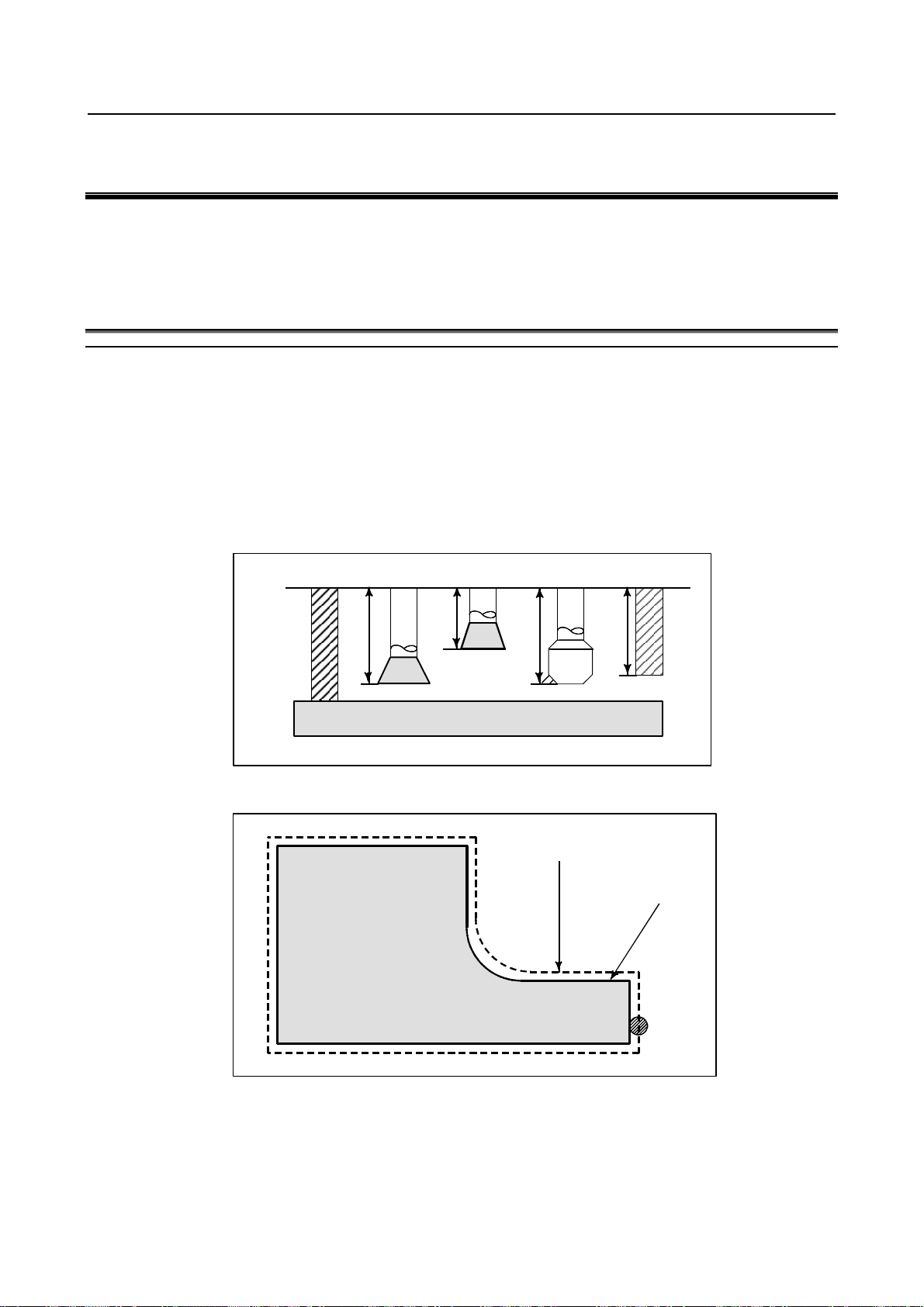
- Machining using the end of cutter - Tool length compensation function
Usually, several tools are used for machining one workpiece. The tools have different tool length. It is
very troublesome to change the program in accordance with the tools.
Therefore, the length of each tool used should be measured in advance. By setting the difference between
the length of the standard tool and the length of each tool in the CNC (See Chapter “Setting and
Displaying Data” in OPERATOR’S MANUAL (Common to Lathe System / Machining Center System)),
machining can be performed without altering the program even when the tool is changed. This function is
called tool length compensation (See Section “Tool Length Compensation” in OPERATOR’S MANUAL
(Common to Lathe System / Machining Center System)).
Standard
H1 H2
tool
Workpiece
H3 H4
- Machining using the side of cutter - Cutter compensation function
ath using cutter compensation
Cutter
Machined part figure
Workpiece
Tool
Because a cutter has a radius, the center of the cutter path goes around the workpiece with the cutter
radius deviated.
If radius of cutters are stored in the CNC (See Chapter “Setting and Displaying Data” in OPERATOR’S
MANUAL (Common to Lathe System / Machining Center System)), the tool can be moved by cutter
radius apart from the machining part figure. This function is called cutter compensation (See Section II-6
“Compensation Function”).
- 9 -
Page 26

2. PREPARATORY FUNCTION
(G FUNCTION)
PROGRAMMING B-63944EN-2/04
2 PREPARATORY FUNCTION
(G FUNCTION)
A number following address G determines the meaning of the command for the concerned block.
G codes are divided into the following two types.
Type Meaning
One-shot G code The G code is effective only in the block in which it is specified.
Modal G code The G code is effective until another G code of the same group is specified.
(Example)
G01 and G00 are modal G codes in group 01.
G01 X_ ;
Z_ ; G01 is effective in this range.
X_ ;
G00 Z_ ; G00 is effective in this range.
X_ ;
G01 X_ ;
:
Explanation
1. When the clear state (bit 6 (CLR) of parameter No. 3402) is set at power-up or reset, the modal G
codes are placed in the states described below.
(1) The modal G codes are placed in the states marked with
(2) G20 and G21 remain unchanged when the clear state is set at power-up or reset.
(3) Which status G22 or G23 at power on is set by bit 7 (G23) of parameter No. 3402. However,
G22 and G23 remain unchanged when the clear state is set at reset.
(4) The user can select G00 or G01 by setting bit 0 (G01) of parameter No. 3402.
(5) The user can select G90 or G91 by setting bit 3 (G91) of parameter No. 3402.
When G code system B or C is used in the lathe system, setting bit 3 (G91) of parameter No.
3402 determines which code, either G90 or G91, is effective.
(6) In the machining center system, the user can select G17, G18, or G19 by setting bits 1 (G18)
and 2 (G19) of parameter No. 3402.
2. G codes other than G10 and G11 are one-shot G codes.
3. When a G code not listed in the G code list is specified, or a G code that has no corresponding
option is specified, alarm PS0010 occurs.
4. Multiple G codes can be specified in the same block if each G code belongs to a different group. If
multiple G codes that belong to the same group are specified in the same block, only the last G code
specified is valid.
5. If a G code belonging to group 01 is specified in a canned cycle for drilling, the canned cycle for
drilling is cancelled. This means that the same state set by specifying G80 is set. Note that the G
codes in group 01 are not affected by a G code specifying a canned cycle for drilling.
6. G codes are indicated by group.
7. The group of G60 is switched according to the setting of the bit 0 (MDL) of parameter No. 5431.
(When the MDL bit is set to 0, the 00 group is selected. When the MDL bit is set to 1, the 01 group
is selected.)
as indicated in Table 2 (a).
- 10 -
Page 27
2.PREPARATORY FUNCTION
B-63944EN-2/04 PROGRAMMING
Table 2 (a) G code list
G code Group Function
G00 Positioning (rapid traverse)
G01 Linear interpolation (cutting feed)
G02 Circular interpolation CW or helical interpolation CW
G03 Circular interpolation CCW or helical interpolation CCW
G02.1, G03.1 Circular thread cutting B CW/CCW
G02.2, G03.2 Involute interpolation CW/CCW
G02.3, G03.3 Exponential interpolation CW/CCW
G02.4, G03.4
G04 Dwell
G05
G05.1 AI contour control / Nano smoothing / Smooth interpolation
G05.4
G06.2 01 NURBS interpolation
G07 Hypothetical axis interpolation
G07.1 (G107) Cylindrical interpolation
G08 AI contour control (advanced preview control compatible command)
G09 Exact stop
G10 Programmable data input
G10.6 Tool retract and recover
G10.9 Programmable switching of diameter/radius specification
G11
G12.1 Polar coordinate interpolation mode
G13.1
G12.4 Groove cutting by continuous circle motion (CW)
G13.4
G15 Polar coordinates command cancel
G16
G17 XpYp plane selection
G18 ZpXp plane selection
G19
G20 (G70) Input in inch
G21 (G71)
G22 Stored stroke check function on
G23
G25 Spindle speed fluctuation detection off
G26
G27 Reference position return check
G28 Automatic return to reference position
G28.2 In-position check disable reference position return
G29 Movement from reference position
G30 2nd, 3rd and 4th reference position return
G30.1 Floating reference position return
G30.2 In-position check disable 2nd, 3rd, or 4th reference position return
G31 Skip function
G31.8
G33 Threading
G34 Variable lead threading
G35 Circular threading CW
G36
01
00
00
21
00
17
02
06
04
19
00
01
3-dimensional coordinate system conversion CW/CCW
AI contour control (high-precision contour control compatible command),
High-speed cycle machining, High-speed binary program operation
HRV3, 4 on/off
Programmable data input mode cancel
Polar coordinate interpolation cancel mode
Groove cutting by continuous circle motion (CCW)
Polar coordinates command
Xp: X axis or its parallel axis
Yp: Y axis or its parallel axis
YpZp plane selection
Input in mm
Stored stroke check function off
Spindle speed fluctuation detection on
EGB-axis skip
Circular threading CCW
Zp: Z axis or its parallel axis
(G FUNCTION)
- 11 -
Page 28

2. PREPARATORY FUNCTION
(G FUNCTION)
PROGRAMMING B-63944EN-2/04
Table 2 (a) G code list
G code Group Function
G37 Automatic tool length measurement
G38 Tool radius/tool nose radius compensation : preserve vector
G39
G40 Tool radius/tool nose radius compensation : cancel
G41
G42
G41.2 3-dimensional cutter compensation : left (type 1)
G41.3 3-dimensional cutter compensation : leading edge offset
G41.4 3-dimensional cutter compensation : left (type 1) (FS16i-compatible command)
G41.5 3-dimensional cutter compensation : left (type 1) (FS16i-compatible command)
G41.6 3-dimensional cutter compensation : left (type 2)
G42.2 3-dimensional cutter compensation : right (type 1)
G42.4 3-dimensional cutter compensation : right (type 1) (FS16i-compatible command)
G42.5 3-dimensional cutter compensation : right (type 1) (FS16i-compatible command)
G42.6
G40.1 Normal direction control cancel mode
G41.1 Normal direction control on : left
G42.1
G43 Tool length compensation +
G44 Tool length compensation G43.1 Tool length compensation in tool axis direction
G43.3 Nutating rotary head tool length compensation
G43.4 Tool center point control (type 1)
G43.5
G45 Tool offset : increase
G46 Tool offset : decrease
G47 Tool offset : double increase
G48
G49 (G49.1) 08 Tool length compensation cancel
G44.9 Spindle unit compensation
G49.9
G50 Scaling cancel
G51
G50.1 Programmable mirror image cancel
G51.1
G50.2 Polygon turning cancel
G51.2
G50.4 Cancel synchronous control
G50.5 Cancel composite control
G50.6 Cancel superimposed control
G51.4 Start synchronous control
G51.5 Start composite control
G51.6 Start superimposed control
G52 Local coordinate system setting
G53 Machine coordinate system setting
G53.1 Tool axis direction control
G53.6
00
07
18
08
00
27
11
22
31
00
Tool radius/tool nose radius compensation : corner circular interpolation
3-dimensional cutter compensation : cancel
Tool radius/tool nose radius compensation : left
3-dimensional cutter compensation : left
Tool radius/tool nose radius compensation : right
3-dimensional cutter compensation : right
3-dimensional cutter compensation : right (type 2)
Normal direction control on : right
Tool center point control (type 2)
Tool offset : double decrease
Spindle unit compensation cancel
Scaling
Programmable mirror image
Polygon turning
Tool center point retention type tool axis direction control
- 12 -
Page 29

2.PREPARATORY FUNCTION
B-63944EN-2/04 PROGRAMMING
Table 2 (a) G code list
G code Group Function
G54 (G54.1) Workpiece coordinate system 1 selection
G55 Workpiece coordinate system 2 selection
G56 Workpiece coordinate system 3 selection
G57 Workpiece coordinate system 4 selection
G58 Workpiece coordinate system 5 selection
G59
G54.2 23 Rotary table dynamic fixture offset
G54.4 33 Workpiece setting error compensation
G60 00 Single direction positioning
G61 Exact stop mode
G62 Automatic corner override
G63 Tapping mode
G64
G65 00 Macro call
G66 Macro modal call A
G66.1 Macro modal call B
G67
G68 Coordinate system rotation start or 3-dimensional coordinate conversion mode on
G69 Coordinate system rotation cancel or 3-dimensional coordinate conversion mode off
G68.2 Tilted working plane command
G68.3 Tilted working plane command by tool axis direction
G68.4
G70.7 Finishing cycle
G71.7 Outer surface rough machining cycle
G72.7 End rough machining cycle
G73.7 Closed loop cutting cycle
G74.7 End cutting off cycle
G75.7 Outer or inner cutting off cycle
G76.7 Multiple threading cycle
G72.1 Figure copying (rotary copy)
G72.2
G73 Peck drilling cycle
G74
G75 01 Plunge grinding cycle
G76 09 Fine boring cycle
G77 Plunge direct sizing/grinding cycle
G78 Continuous-feed surface grinding cycle
G79
G80 09
G80.4 Electronic gear box: synchronization cancellation
G81.4
G80.5 Electronic gear box 2 pair: synchronization cancellation
G81.5
G81 09
G81.1 00 Chopping
14
15
12
16
00
09
01
34
24
Workpiece coordinate system 6 selection
Cutting mode
Macro modal call A/B cancel
Tilted working plane command (incremental multi-command)
Figure copying (linear copy)
Left-handed tapping cycle
Intermittent-feed surface grinding cycle
Canned cycle cancel
Electronic gear box : synchronization cancellation
Electronic gear box: synchronization start
Electronic gear box 2 pair: synchronization start
Drilling cycle or spot boring cycle
Electronic gear box : synchronization start
(G FUNCTION)
- 13 -
Page 30

2. PREPARATORY FUNCTION
(G FUNCTION)
PROGRAMMING B-63944EN-2/04
Table 2 (a) G code list
G code Group Function
G82 Drilling cycle or counter boring cycle
G83 Peck drilling cycle
G84 Tapping cycle
G84.2 Rigid tapping cycle (FS15 format)
G84.3 Left-handed rigid tapping cycle (FS15 format)
G85 Boring cycle
G86 Boring cycle
G87 Back boring cycle
G88 Boring cycle
G89
G90 Absolute programming
G91
G91.1 Checking the maximum incremental amount specified
G92 Setting for workpiece coordinate system or clamp at maximum spindle speed
G92.1
G93 Inverse time feed
G94 Feed per minute
G95
G96 Constant surface speed control
G97
G96.1 Spindle indexing execution (waiting for completion)
G96.2 Spindle indexing execution (not waiting for completion)
G96.3 Spindle indexing completion check
G96.4
G98 Canned cycle : return to initial level
G99
G107 00 Cylindrical interpolation
G112 Polar coordinate interpolation mode
G113
G160 In-feed control cancel
G161
09
03
00
05
13
00
10
21
20
Boring cycle
Incremental programming
Workpiece coordinate system preset
Feed per revolution
Constant surface speed control cancel
SV speed control mode ON
Canned cycle : return to R point level
Polar coordinate interpolation mode cancel
In-feed control
- 14 -
Page 31

B-63944EN-2/04 PROGRAMMING 3.INTERPOLATION FUNCTION
3 INTERPOLATION FUNCTION
Chapter 3, "INTERPOLATION FUNCTION", consists of the following sections:
3.1 INVOLUTE INTERPOLATION (G02.2, G03.2)...............................................................................15
3.2 THREADING (G33)...........................................................................................................................24
3.3 CIRCULAR THREAD CUTTING B (G2.1,G3.1).............................................................................25
3.4 GROOVE CUTTING BY CONTINUOUS CIRCLE MOTION (G12.4, G13.4)...............................28
3.1 INVOLUTE INTERPOLATION (G02.2, G03.2)
Overview
Involute curve machining can be performed by using involute interpolation. Cutter compensation can be
performed. Involute interpolation eliminates the need for approximating an involute curve with minute
segments or arcs, and continuous pulse distribution is ensured even in high-speed operation of small
blocks. Accordingly, high-speed operation can be performed smoothly. Moreover, machining programs
can be created more easily, and the size of machining programs can be reduced.
In involute interpolation, the following two types of feedrate override functions are automatically
executed, and a favorable cutting surface can be formed with high precision. (Automatic speed control
function for involute interpolation)
• Override in cutter compensation mode
• Override in the vicinity of basic circle
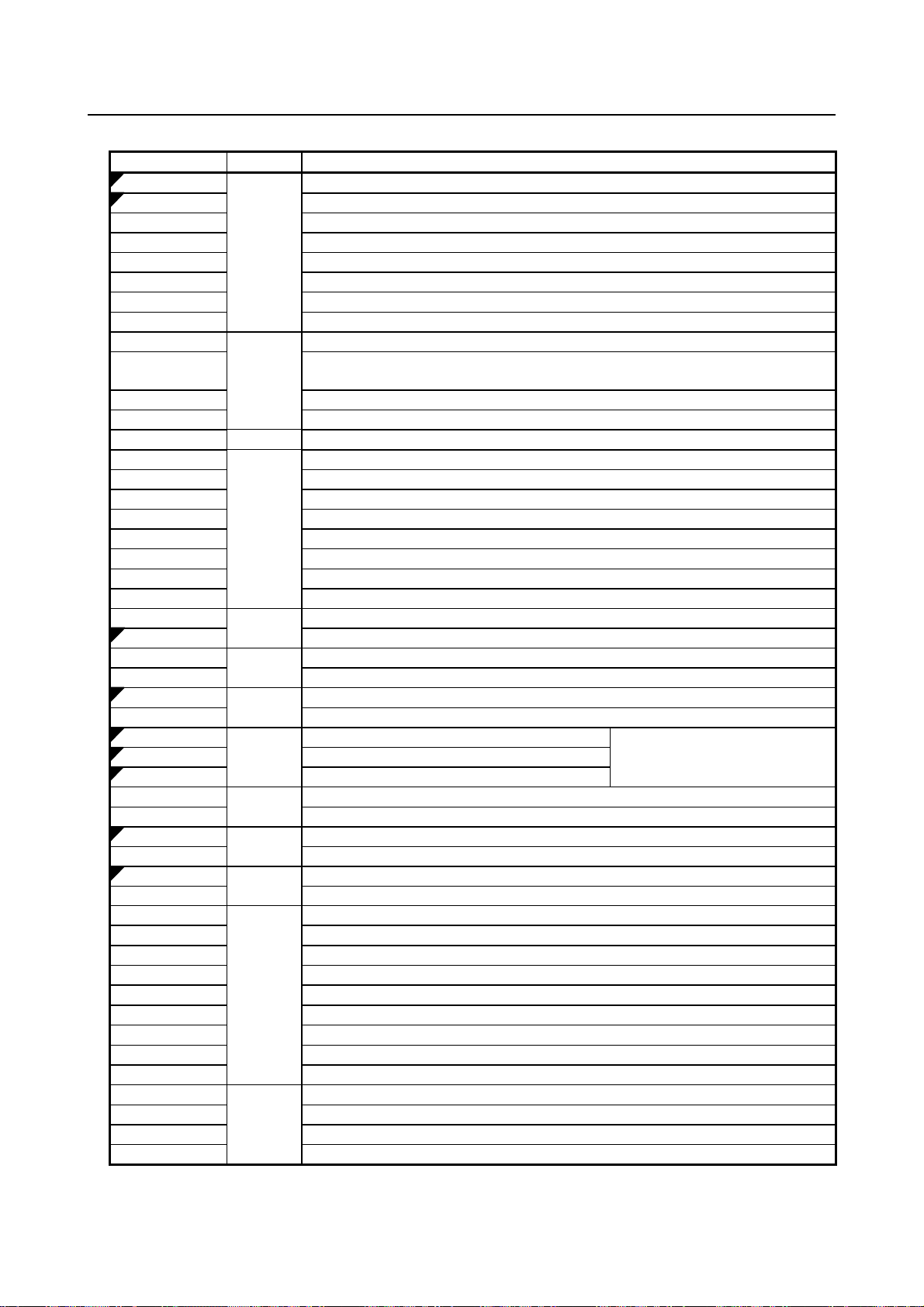
Format
Involute interpolation on the Xp-Yp plane
G17 G02.2 Xp_ Yp_ I_ J_ R_ F_ ;
G17 G03.2 Xp_ Yp_ I_ J_ R_ F_ ;
Involute interpolation on the Zp-Xp plane
G18 G02.2 Zp_ Xp_ K_ I_ R_ F_ ;
G18 G03.2 Zp_ Xp_ K_ I_ R_ F_ ;
Involute interpolation on the Yp-Zp plane
G19 G02.2 Yp_ Zp_ J_ K_ R_ F_ ;
G19 G03.2 Yp_ Zp_ J_ K_ R_ F_ ;
Where,
G02.2 : Involute interpolation (clockwise)
G03.2 : Involute interpolation (counterclockwise)
G17/G18/G19 : Xp-Yp/Zp-Xp/Yp-Zp plane selection
Xp_ : X-axis or an axis parallel to the X-axis (specified in a parameter)
Yp_ : Y-axis or an axis parallel to the Y-axis (specified in a parameter)
Zp_ : Z-axis or an axis parallel to the Z-axis (specified in a parameter)
I_, J_, K_ : Center of the base circle for an involute curve viewed from the start point
R_ : Base circle radius
F_ : Cutting feedrate
- 15 -
Page 32

3.INTERPOLATION FUNCTION PROGRAMMING B-63944EN-2/04
Explanation
Involute curve machining can be performed by using involute interpolation. Involute interpolation
ensures continuous pulse distribution even in high-speed operation in small blocks, thus enabling smooth
and high-speed machining. Moreover, machining programs can be created more easily, and the size of
machining programs can be reduced.
Yp
0
End point
Pe
Po
R
Start
point
Yp
Ps
J
I
Base circle
Clockwise involute interpolation (G02.2)
Xp
Yp
Yp
Po
Ps
I
R
Pe
J
End point
Xp
0
End point
Ro
J
Start point
Ps
Pe
Xp
End
point
Pe
Counterclockwise involute interpolation (G03.2)
I
J
0
R
Start point
Ps
Po
Xp
R
0
I
Fig. 3.1 (a) Actual movement
- Involute curve
An involute curve on the X-Y plane is defined as follows ;
X (θ) = R [cos θ + (θ - θO) sin θ] + XO
Y (θ) = R [sin θ - (θ - θO) cos θ] + YO
where,
XO, YO : Coordinates of the center of a base circle
R : Base circle radius
θO : Angle of the start point of an involute curve
θ : Angle of the point where a tangent from the current position to the base circle contacts the
base circle
X (θ), Y (θ) : Current position on the X-axis and Y-axis
- 16 -
Page 33

B-63944EN-2/04 PROGRAMMING 3.INTERPOLATION FUNCTION
Y
Start point
R
θ
o
θ
(Xo, Yo)
Involute curve
(X, Y)
End point
Base circle
Fig. 3.1 (b) Involute curve
X
Involute curves on the Z-X plane and Y-Z plane are defined in the same way as an involute curve on the
X-Y plane.
- Start point and end point
The end point of an involute curve is specified using address Xp, Yp, or Zp. An absolute value or
incremental value is used to specify an Xp, Yp, or Zp value. When using an incremental value, specify
the coordinates of the end point viewed from the start point of the involute curve.
When no end point is specified, alarm PS0241 is issued.
If the specified start point or end point lies within the base circle, alarm PS0242 is issued. The same alarm
is issued if cutter compensation C causes the offset vector to enter the base circle. Be particularly careful
when applying an offset to the inside of an involute curve.
- Base circle specification
The center of a base circle is specified with I, J, and K, corresponding to X, Y, and Z. The value
following I, J, or K is a vector component defined when the center of the base circle is viewed from the
start point of the involute curve; this value must always be specified as an incremental value, regardless
of the G90/G91 setting. Assign a sign to I, J, and K according to the direction.
If I, J, and K are all left unspecified, or I0, J0, K0 is specified, alarm PS0241 or PS0242 is issued.
If R is not specified, or R ≤ 0, alarm PS0241 or PS0242 is issued.
- Choosing from two types of involute curves
When only a start point and I, J, and K data are given, two types of involute curves can be created. One
type of involute curve extends towards the base circle, and the other extends away from the base circle.
When the specified end point is closer to the center of the base circle than the start point, the involute
curve extends toward the base circle. In the opposite case, the involute curve extends away from the base
circle.
- Feedrate
The cutting feedrate specified in an F code is used as the feedrate for involute interpolation. The feedrate
along the involute curve (feedrate along the tangent to the involute curve) is controlled to satisfy the
specified feedrate.
- Plane selection
As with circular interpolation, the plane to which to apply involute interpolation can be selected using
G17, G18, and G19.
- Cutter compensation
Cutter compensation can be applied to involute curve machining. As with linear and circular interpolation,
G40, G41, and G42 are used to specify cutter compensation.
G40: Cutter compensation cancel
- 17 -
Page 34

3.INTERPOLATION FUNCTION PROGRAMMING B-63944EN-2/04
G41: Cutter compensation left
G42: Cutter compensation right
First, a point of intersection with a segment or an arc is approximated both at the start point and at the end
point of the involute curve. An involute curve passing the two approximated points of intersection with
the start point and end pint becomes the tool center path.
Before selecting the involute interpolation mode, specify G41 or G42, cancel involute interpolation, and
then specify G40. G41, G42, and G40 for cutter compensation cannot be specified in the involute
interpolation mode.
- Automatic speed control
Cutting precision can be improved by automatically overriding the programmed feedrate during involute
interpolation. See a subsequent subsection, "Automatic Speed Control for Involute Interpolation."
- Specifiable G codes
The following G codes can be specified in involute interpolation mode:
G04 : Dwell
G10 : Programmable data input
G17 : X-Y plane selection
G18 : Z-X plane selection
G19 : Y-Z plane selection
G65 : Macro call
G66 : Macro modal call
G67 : Macro modal call cancel
G90 : Absolute programming
G91 : Incremental programming
- Modes that allow involute interpolation specification
Involute interpolation can be specified in the following G code modes:
G41 : Cutter compensation left
G42 : Cutter compensation right
G51 : Scaling
G51.1 : Programmable mirror image
G68 : Coordinate rotation
- End point error
As shown below the end point may not be located on an involute curve that passes through the start point
(Fig. 3.1 (c)).
When an involute curve that passes through the start point deviates from the involute curve that passes
through the end point by more than the value set in parameter No. 5610, alarm PS0243 is issued.
If there is an end point error, the programmed feedrate changes by the amount of error.
X
End point
Pe
Path after correction
Deviation
Start point
Ps
Correct involute curve
Y
Fig. 3.1 (c) End point error in counterclockwise involute interpolation (G03.2)
- 18 -
Page 35

B-63944EN-2/04 PROGRAMMING 3.INTERPOLATION FUNCTION
3.1.1 Automatic Speed Control for Involute Interpolation
This function automatically overrides the programmed feedrate in two different ways during involute
interpolation. With this function, a favorable cutting surface can be formed with high precision.
• Override in cutter compensation mode
• Override in the vicinity of basic circle
- Override in cutter compensation mode
When cutter compensation is applied to involute interpolation, control is exercised in ordinary involute
interpolation so that the tangential feedrate on the tool-center path always keeps the specified feedrate.
Under the control, the actual cutting feedrate (feedrate around the perimeter of the tool (cutting point) on
the path specified in the program) changes because the curvature of the involute curve changes every
moment.
If the tool is offset in the inward direction of the involute curve in particular, the actual cutting feedrate
becomes higher than the specified feedrate as the tool gets nearer to the base circle.
For smooth machining, it is desirable to control the actual cutting feedrate so that the feedrate keeps the
specified feedrate. This function calculates an appropriate override value for the ever-changing curvature
of the involute curve in the involute interpolation mode after cutter compensation. The function also
controls the actual cutting feedrate (tangential feedrate at the cutting point) so that it always keeps the
specified feedrate.
Cutting point
Rofs
Rcp
Base
circle
Fig. 3.1 (d) Override for inward offset by cutter compensation
Path specified in
the program
Inward offset
OVR = Rcp/(Rcp + Rofs) × 100
Outward offset
OVR = Rcp/(Rcp - Rofs) × 100
where,
Rcp : Radius of curvature at the center of the tool of the involute curve passing through the center of
the tool
Rofs : Radius of the cutter
- Clamping the override
The lower limit of override is specified in parameter No. 5620 so that the override for inward offset by
cutter compensation or the override in the vicinity of the basic circle will not bring the speed of the tool
center to zero in the vicinity of the basic circle.
The lower limit of override (OVR1o) is specified in parameter No. 5620 so that the inward offset will not
reduce the speed of the tool center to a very low level in the vicinity of the basic circle.
- 19 -
Page 36

3.INTERPOLATION FUNCTION PROGRAMMING B-63944EN-2/04
Accordingly, the feedrate is clamped but does not fall below the level determined by the programmed
feedrate and the lower limit of override (OVR1o).
The outward offset may increase the override to a very high level, but the feedrate will not exceed the
maximum cutting feedrate.
- Clamping the acceleration in the vicinity of basic circle
If the acceleration calculated from the radius of curvature of the involute curve exceeds a value specified
in the corresponding parameter, the tangential velocity is controlled so that the actual acceleration will not
exceed the value specified in the parameter. Because the acceleration is always limited to a constant level,
efficient velocity control can be performed for each machine. Because smooth velocity control can be
performed continuously, impacts in machining in the vicinity of the basic circle can be reduced.
To calculate the acceleration, the radius of curvature of the involute curve and the tangential velocity are
substituted into the following formula of circular acceleration:
Acceleration = F × F/R
F: Tangential velocity
R: Radius of curvature
The maximum permissible acceleration is specified in parameter No. 1735.
If the calculated acceleration exceeds the maximum permissible acceleration, the feedrate is clamped to
the level calculated by the following expression:
onaccelerati epermissibl Maximum curvature of Radius level Clamp ×=
If the calculated clamp level falls below the lower limit of feedrate, the lower limit of feedrate becomes
the clamp level. The lower limit of feedrate is specified in parameter No. 1732.
- 20 -
Page 37
B-63944EN-2/04 PROGRAMMING 3.INTERPOLATION FUNCTION
3.1.2 Helical Involute Interpolation (G02.2, G03.2)
As with arc helical involute interpolation, this function performs helical involute interpolation on the two
axes involute interpolation and on up to four other axes simultaneously.
Format
Helical involute interpolation in Xp-Yp plane
G02.2
G17 Xp Yp I J R α β γ δ F ;
G03.2
Helical involute interpolation in Zp-Xp plane
G02.2
G18 Zp Xp K I R α β γ δ F ;
G03.2
Helical involute interpolation in Yp-Zp plane
G02.2
G19 Yp Zp J K R α β γ δ F ;
G03.2
α, β, γ, δ : Optional axis other than the axes of involute interpolation. Up to four axes can
be specified.
- 21 -
Page 38

3.INTERPOLATION FUNCTION PROGRAMMING B-63944EN-2/04
3.1.3 Involute Interpolation on Linear Axis and Rotary Axis
(G02.2, G03.2)
By performing involute interpolation in the polar coordinate interpolation mode, involute cutting can be
carried out. Cutting is performed along an involute curve drawn in the plane formed by a linear axis and a
rotary axis.
Format
If the linear axis is the X-axis or an axis parallel to the X-axis, the plane is considered to
be the Xp-Yp plane, and I and J are used.
G02.2
X
C I J R F ;
G03.2
If the linear axis is the Y-axis or an axis parallel to the Y-axis, the plane is considered to
be the Yp-Zp plane, and J and K are used.
G02.2
Y
C J K R F ;
G03.2
If the linear axis is the Z-axis or an axis parallel to the Z-axis, the plane is considered to
be the Zp-Xp plane, and K and I are used.
G02.2
Z C K I R F ;
G03.2
G02.2 : Clockwise involute interpolation
G03.2 : Counterclockwise involute interpolation
Example) If the linear axis is the X-axis
X, C : End point of the involute curve
I, J : Center of the basic circle of the involute curve, viewed from the start point
R : Radius of basic circle
F : Cutting feedrate
- 22 -
Page 39

B-63944EN-2/04 PROGRAMMING 3.INTERPOLATION FUNCTION
Example
C (Imaginary axis)
Path after tool
compensation
Programmed path
N202
N204
N205
N201
C-axis
Tool
X-axis
N200
N203
Fig. 3.1 (e) Involute interpolation in the polar coordinate interpolation mode
Z-axis
O0001 ;
:
:
N010 T0101 ;
:
:
N100 G90 G00 X15.0 C0 Z0 ; Positioning to the start point
N200 G12.1 ; Polar coordinate interpolation started
N201 G41 G00 X-1.0 ;
N202 G01 Z-2.0 F
;
N203 G02.2 X1.0 C9.425 I1.0 J0 R1.0 ; Involute interpolation during polar coordinate interpolation
N204 G01 Z0 ;
N205 G40 G00 X15.0 C0 ;
N206 G13.1 ; Polar coordinate interpolation cancelled
N300 Z ;
N400 X
C ;
:
:
M30 ;
Limitation
- Number of involute curve turns
Both the start point and end point must be within 100 turns from the point where the involute curve starts.
An involute curve can be specified to make one or more turns in a single block.
If the specified start point or end point is beyond 100 turns from the point where the involute curve starts,
alarm PS0242 is issued.
- Unspecifiable functions
In involute interpolation mode, optional chamfering and corner R cannot be specified.
- 23 -
Page 40

3.INTERPOLATION FUNCTION PROGRAMMING B-63944EN-2/04
- Mode that does not allow involute interpolation specification
Involute interpolation cannot be used in the following mode:
G07.1: Cylindrical interpolation
3.2 THREADING (G33)
Straight threads with a constant lead can be cut. The position coder mounted on the spindle reads the
spindle speed in real-time. The read spindle speed is converted to the feedrate per minute to feed the tool.
Format
Z
G33IP_ F_ ;
F :Long axis direction lead
Workpiece
X
Explanation
In general, threading is repeated along the same tool path in rough cutting through finish cutting for a
screw. Since threading starts when the position coder mounted on the spindle outputs a 1-turn signal,
threading is started at a fixed point and the tool path on the workpiece is unchanged for repeated
threading. Note that the spindle speed must remain constant from rough cutting through finish cutting. If
not, incorrect thread lead will occur.
In general, the lag of the servo system, etc. will produce somewhat incorrect leads at the starting and
ending points of a thread cut. To compensate for this, a threading length somewhat longer than required
should be specified.
Table 3.2 (a) lists the ranges for specifying the thread lead.
Table 3.2 (a) Ranges of lead sizes that can be specified
Least command increment Command value range of the lead
Metric input
Inch input
NOTE
1 The spindle speed is limited as follows :
1 ≤ spindle speed ≤ (Maximum feedrate) / (Thread lead)
Spindle speed : min-1
Thread lead : mm or inch
Maximum feedrate : mm/min or inch/min ; maximum command-specified
feedrate for feed-per-minute mode or maximum feedrate that is determined
based on mechanical restrictions including those related to motors, whichever is
smaller
0.001 mm F1 to F50000 (0.01 to 500.00mm)
0.0001 mm F1 to F50000 (0.01 to 500.00mm)
0.0001 inch F1 to F99999 (0.0001 to 9.9999inch)
0.00001 inch F1 to F99999 (0.0001 to 9.9999inch)
- 24 -
Page 41

B-63944EN-2/04 PROGRAMMING 3.INTERPOLATION FUNCTION
NOTE
2 Cutting feedrate override is not applied to the converted feedrate in all machining
process from rough cutting to finish cutting. The feedrate is fixed at 100%
3 The converted feedrate is limited by the upper feedrate specified.
4 Feed hold is disabled during threading. Pressing the feed hold key during
threading causes the machine to stop at the end point of the next block after
threading (that is, after the G33 mode is terminated)
Example
Threading at a pitch of 1.5mm
G33 Z10. F1.5;
3.3 CIRCULAR THREAD CUTTING B (G2.1,G3.1)
Overview
Circular thread cutting B can perform circular interpolation on two axes and, at the same time, can
perform linear interpolation between the major axis of the two axes subject to circular interpolation,
which has a longer traveling distance, and up to two other, arbitrary axes. This circular thread cutting
function does not move the tool in synchronization with the rotation of the spindle (workpiece) using the
spindle motor, but controls the rotation of the workpiece using a servo motor (rotation axis) to perform
threading at equal pitches along cylindrical material, grooving, tool grinding, and other machining.
Application example
For example, the grooving shown in Fig. 3.3 (a) can be performed by executing circular interpolation on
the ZpXp plane in synchronization with linear interpolation on the Z-axis and the C-axis.
X axis
Z axis
C axis
Fig. 3.3 (a) Example of grooving
- 25 -
Page 42

3.INTERPOLATION FUNCTION PROGRAMMING B-63944EN-2/04
A
r
Format
Xp-Yp plane
G17
G02.1
G03.1
X
Y
α β
I
J
R
F
;
Zp-Xp plane
Z
X
G18
G02.1
G03.1
α β
K
R
I
F
;
Yp-Zp plane
Y
Z
G19
G02.1
G03.1
α β
G02.1: Clockwise circular thread cutting B command
G03.1: Counterclockwise circular thread cutting B command
X,Y,Z: Coordinates of the end point for circular interpolation
α,β: Coordinates of the end point for linear interpolation
I,J,K: Signed distance from the start point to the center of an arc
R: Arc radius
F: Feedrate in the major axis direction
α and β are arbitrary axes other than the circular interpolation axis. Up to two such axes
can be specified.
X, Y, Z, I, J, K, and R are the same as those for G02 and G03.
In the case of the ZpXp plane, the major axis being the Z-axis, the minor axis
being the X-axis, the arbitrary axis being the C-axis, and clockwise direction
G91 G18 G02.1 Z_ C_ I_ K_ F_
R_
J
R
K
F
;
X axis
Start point
I
R
K
Fig. 3.3 (b)
rc cente
End point (X,Z)
C axis
Z axis
Explanation
Circular thread cutting B can perform circular interpolation on two axes and, at the same time, can
perform linear interpolation between the major axis of the two axes subject to circular interpolation,
which has a longer traveling distance, and up to two other, arbitrary axes. This circular thread cutting
function does not move the tool in synchronization with the rotation of the spindle (workpiece) using the
spindle motor, but controls the rotation of the workpiece using a servo motor (rotation axis) to perform
threading at equal pitches along cylindrical material, grooving, tool grinding, and other machining.
- 26 -
Page 43

B-63944EN-2/04 PROGRAMMING 3.INTERPOLATION FUNCTION
p
- Relationship between major axis and minor axis
The relationship between the major axis and minor axis is as shown in Fig. 3.3 (c).
End
point
Y
ΔX
45° 45°
Center
Start
oint
If |ΔX| > |ΔY|,
ΔY
the major axis is the X-axis, and the
minor axis is the Y-axis.
If |ΔX| < |ΔY|,
the major axis is the Y-axis, and the
minor axis is the X-axis.
X
Fig. 3.3 (c)
When diameter programming is used, the relationship between the major axis and minor axis is judged
with the radius value.
- Permissible arc range
If the arc goes beyond the range shown in Fig. 3.3 (d) or Fig. 3.3 (e), alarm PS2070 is issued.
Minor
axis
Major
axis
Major
axis
90°
45° 45°
45°45°
Fig. 3.3 (d)
90°
45°
45°
45° to 135°
225° to 315°
0°
Rotation
axis
Range in which
interpolation is
enabled
0°
Minor
axis
45°45°
Fig. 3.3 (e)
Rotation
axis
315° to 45°
135° to 225°
Range in which
interpolation is enabled
- Feedrate
If the specified feedrate for the major axis is F, the feedrate for the minor axis Fs and feedrate for the α
axis Fα are expressed as follows.
Length of α axis
Fα = F × (The maximum value is the maximum cutting feedrate for each axis.)
Length of major axis
Fs = F × TAN θ
θ: Angle of a tangent to the major axis
- 27 -
Page 44

3.INTERPOLATION FUNCTION PROGRAMMING B-63944EN-2/04
End
θ
Minor
axis
Start point
Major
axis
Fig. 3.3 (f)
Fs
point
F
Center
- Tool radius compensation
Tool radius compensation applies only to two axes of the plane on which circular interpolation is
performed.
Limitation
- Tool offset and tool length compensation
In a block in which circular thread cutting B is specified, tool offset or tool length compensation cannot
be specified.
- I,J,K and the R command
Either I,J,K or the R command cannot be omitted.
- Unavailable functions
Circular thread cutting B cannot be used together with the following functions:
• 3-dimensional cutter compensation
• Tool center point control
3.4 GROOVE CUTTING BY CONTINUOUS CIRCLE MOTION
(G12.4, G13.4)
Overview
Groove cutting with a width greater than the tool diameter can be performed by causing the tool to make
continuous circle motion independently of axis movement by the groove cutting path program and
superposing the continuous circle motion on the axis movement by the groove cutting path program.
Continuous
circle motion
Groove cutting path
specification route
Fig. 3.4 (a)
- 28 -
Page 45

B-63944EN-2/04 PROGRAMMING 3.INTERPOLATION FUNCTION
Format
G12.4
P1Ii Kk Qq Ff; (Mode on)
G13.4
:
: (Groove cutting path program)
:
G12.4
P0; (Mode cancel)
G13.4
G12.4 : Clockwise continuous circle motion
G13.4 : Counterclockwise continuous circle motion
i : Groove width
k : Tool diameter
q : Travel distance in the groove cutting direction per continuous circle motion (pitch)
f : Feedrate (speed of the center of a tool that performs continuous circle motion)
Groove cutting path program
i (Groove width)
k (Tool diameter)
q (pitch)
Fig. 3.4 (b)
NOTE
1 In the G12.4/G13.4 blocks, addresses other than the commands mentioned
above cannot be used.
2 If bit 4 (GCC) of parameter No. 3452 is 0, continuous circle motion stops due to
the stoppage of axis movement by the groove cutting path program, but because
axis movement by the groove cutting path program is independent of continuous
circle motion, the stoppage will not exactly be at the position of continuous circle
motion converted from the groove cutting path program and the pitch.
Explanation
- Mode on
The continuous circle motion-based groove cutting mode sets continuous circle motion-based groove
cutting mode to the on state. The continuous circle motion-based groove cutting enable signal must be
"1".
- 29 -
Page 46

3.INTERPOLATION FUNCTION PROGRAMMING B-63944EN-2/04
If the mode on command is specified with the continuous circle motion-based groove cutting enable
signal being "0", alarm PS0010 is issued.
No axis movement is performed with the continuous circle motion-based groove cutting mode on
command.
- Mode cancel
The continuous circle motion-based groove cutting mode cancel command causes the tool to move with
cutting feed (continuous circle motion speed) from the present position on the continuous circle to the
end-specified position (groove center) of the groove cutting path program. After the end of movement, the
command sets continuous circle motion-based groove cutting mode to the cancel state.
- Startup
In the first move command block of the groove cutting path program, the tool moves to a point on the
continuous circle with cutting feed (continuous circle motion speed). After the end of the movement to a
point on the continuous circle, continuous circle motion is started in synchronization with the move
command of the groove cutting path program.
Depending on the first move command block of the groove cutting path program, the direction of startup
varies.
• In the case of an axis command perpendicular to a plane or if there is no movement along an axis
used to form the currently selected plane
Assuming that R = (I-K)/2, the following holds true: (X,Y) = (-R,0)
R
Startup
Groove cutting
path command
Z
Y
X
• If there is movement along an axis used to form the selected plane
Direction opposite to the direction of movement projected onto the currently selected plane
Groove cutting path command
End
Startup
R
Start point
point
Y
X
- Increments systems for horizontal w i dth, tool diameter, and pitch
The increment systems for i (horizontal width), K (tool diameter), and q (pitch) follow the incremental
system of the reference axis (parameter No. 1031).
- Feedrate
For the feedrate F, specify the central speed of the tool that performs continuous circle motion.
The speed on the groove cutting path is:
Speed on the groove cutting path = F × Q / π (I-K)
- Pitch
If the pitch is large, there may be portions left uncut. The tool diameter must be greater than the pitch.
- 30 -
Page 47

B-63944EN-2/04 PROGRAMMING 3.INTERPOLATION FUNCTION
- Groove cutting path program
The groove cutting path program specifies the path of the center of continuous circle motion.
(1) Effective commands
The groove cutting path program can execute only the G01, G02, G03, G04, G90, G91, and
auxiliary functions. The G00 command causes alarm PS5256. By setting bit 0 (GG0) of parameter
No. 3452, however, the G00 command can be moved as G01 movement. The modal code changes
from G00 to G01.
(2) Specifying a controlled axis
The groove cutting path program can specify the control axes below.
• Commands for the axes forming a plane
• Commands for axes perpendicular to a plane (independent command for the Z-axis)
• Commands for linear axes other than the axes forming a plane
• Commands for rotation axes
(3) Specification of a pitch in a move command block
In addition to the specification of a pitch with the continuous circle motion-based groove cutting
mode on command, a pitch can be specified in each move command block.
The pitch specification is modal; the pitch last specified is effective from the time the mode is
entered with G12.4P1/G13.4P1 until the mode is exited.
(4) Command example
(Example 1) Example of a command for an axis perpendicular to a plane
(independent command for the Z-axis)
:
G12.4 P1 Ii Kk Ff ;
G01 Z--- Q--- ; Specify the pitch for the Z-axis (pitch of this block).
X--- Y--- Q--- ; Specify the pitch for the X- and Y-axes (pitch of the
subsequent blocks)
:
For a command for the Z-axis only, the pitch is regarded as the travel distance in
the Z-axis direction.
(Example 2) If a move command for other than a plane is included
:
G12.4P1 Ii Kk Ff ;
G01 X--- Y--- Z--- Q--- ; This is a pitch on a slanted path.
:
The pitch is the travel distance in the synthetic direction of the X-, Y-, and
Z-axes.
(Example 3) Pitch switching
:
G12.4P1 Ii Kk Ff ;
G01 X--- Y--- Q--- ;
X--- Y--- Q--- ; Specify Q in the block in which the pitch is to be changed.
:
The pitch is the travel distance in the synthetic direction of the specified axes.
- 31 -
Page 48

3.INTERPOLATION FUNCTION PROGRAMMING B-63944EN-2/04
A
(Example 4) Command containing a rotation axis
:
G12.4P1 Ii Kk Ff ;
G01 A--- Q--- ;
X--- Y--- ; Specify Q in the block in which the pitch is to be changed.
:
The increment system for Q follows that of the reference axis. Thus, if the
increment system for the reference axis is IS-B, the pitch Q100 will be 0.1°.
So that a cut along the Z-axis will start after the stabilization of the radius of continuous circle motion, the
continuous circle motion-based groove cutting mode on command must be specified in the air, apart from
the cut position by at least the pitch per rotation. Cutting with a constant groove width is possible by
letting the tool escape in the Z-axis direction at the end of cutting while keeping continuous circle motion
and then after the tool comes out into the air, executing the continuous circle motion-based groove cutting
mode cancel command to stop continuous circle motion.
NOTE
The radius of continuous circle motion is smaller than that specified at the start
of continuous circle motion, and is larger when continuous circle motion comes
to a deceleration stop. In the steady state, the radius is smaller than that
specified. This is an error that occurs due to acceleration/deceleration after
information and the delay of the servo system.
Error that occurs due to
acceleration/deceleration after
interpolation and the delay of the servo
system
Specified
ctual path
- Mode in progress signal
This signal notifies the PMC that continuous circle motion-based groove cutting mode is in progress.
The signal is set to "1" if continuous circle motion-based groove cutting mode is turned on.
The signal is set to "0" if continuous circle motion-based groove cutting mode is canceled.
- Clamping the feedrate with the acceleration of continuous circle motion
Using the I and K commands in G12.4/13.4 and the acceleration clamp value for continuous circle motion
(parameter No. 3490), the feedrate command F for continuous circle motion can be clamped.
Clamp feedrate F = SQR (parameter No.3490 × (I-K) / 2)× 60
Example If parameter No. 3490 = 100
If G13.4 P1 I10.0 K5.0 Q1.0 F1000 ;, clamp feedrate = 948. Thus, execution with
an F value of 948
If G13.4 P1 I10.0 K8.0 Q1.0 F1000 ;, clamp feedrate = 600. Thus, execution with
an F value of 600
If G13.4 P1 I10.0 K9.0 Q1.0 F1000 ;, clamp feedrate = 424. Thus, execution with
an F value of 424
A continuous circle motion feedrate override is applied to the clamped feedrate.
- 32 -
Page 49

B-63944EN-2/04 PROGRAMMING 3.INTERPOLATION FUNCTION
- Acceleration deceleration after interpolation
In continuous circle motion-based groove cutting mode, acceleration/deceleration after interpolation is
enabled.
- Selecting stoppage conditions
(1) Stoppage of continuous circle motion due to a feed hold, single block, etc.
It can be selected whether to continue or stop continuous circle motion when a specified operation is
stopped due to one of the various stoppage conditions such as a feed hold and a single block, using a
parameter:
Bit 4 (GCC) of parameter No. 3452 = 0 : Stops continuous circle motion.
Bit 4 (GCC) of parameter No. 3452 = 1 : Continues continuous circle motion.
(2) Stoppage condition/mode switching
The conditions for groove cutting path operation, continuous circle motion stoppage/continuation,
and switching to operation mode in connection with stoppage conditions are as given in Table 3.4
(a).
Table 3.4 (a)
Continuous circle motion
Stoppage condition
Feed hold Deceleration stop Deceleration stop Continuation Possible after the stoppage
Single block Deceleration stop Deceleration stop Continuation Possible after the stoppage
Switching to manual
mode
Switching between
auto modes
MDI operation Deceleration stop Deceleration stop Continuation Possible after the stoppage
Pitch override of 0% Deceleration stop Deceleration stop Continuation Possible after the stoppage
M/S/T code FIN
awaiting
Programming error Deceleration stop Decelerati on stop Continuation Possible after the stoppage
Overheat alarm Deceleration stop Deceleration stop Continuation Possible after the stoppage
BG edit alarm Continuation Continuation Continuation Automatic operation does
Mode end Deceleration stop Withdrawal by the
Reset Deceleration stop Deceleration stop Deceleration stop Possible after the end of all
Machine lock *1 Deceleration stop Deceleration stop Deceleration stop
Servo off *1 Deceleration stop Deceleration stop Deceleration stop
Interlock *2 Deceleration stop Deceleration stop Deceleration stop
OT alarm Deceleration stop Deceleration stop Deceleration stop Possible after the end of all
DS alarm Deceleration stop Deceleration stop Deceleration stop Possible after the end of all
Groove cutting
path operation
Deceleration stop Deceleration stop Continuation To be performed after the
Deceleration stop Deceleration stop Continuation Possible after the stoppage
Deceleration stop Deceleration stop Continuation Possible after the stoppage
stoppage/continuation
Stoppage
(GCC = 0)
radius/
deceleration stop
Continuation
(GCC = 1)
Withdrawal by the
radius/
deceleration stop
Switching to operation
mode
of path operation
of path operation
stoppage of path operation
of path operation
of path operation
of path operation
of path operation
of path operation
of path operation
not stop.
Follows other stoppage
conditions.
operations
―――
―――
―――
operations
operations
- 33 -
Page 50

3.INTERPOLATION FUNCTION PROGRAMMING B-63944EN-2/04
Continuous circle motion
Stoppage condition
Emergency stop Immediate stop Immediate stop Immediate stop Possible after an
PC-related alarm Immediate stop Immediate stop Immediate stop Possible after an alarm is
Servo alarm Immediate stop Immediate stop Immediate stop Possible after an alarm is
Spindle alarm Immediate stop Immediate stop Immediate stop Possible after an alarm is
System alarm Immediate stop Immediate stop Immediate stop The power must be turned
Groove cutting
path operation
stoppage/continuation
Stoppage
(GCC = 0)
Continuation
(GCC = 1)
Switching to operation
mode
emergency stop is
canceled
canceled
canceled
canceled
off and then back on.
*1: Stoppage occurs only on the axis on which the function is enabled.
*2: Stoppage occurs on all axes if the function is enabled on at least one axis.
• If bit 4 (GCC) of parameter No. 3452 is 0, continuous circle motion stops due to the stoppage of axis
movement by the groove cutting path program, but because axis movement by the groove cutting
path program is independent of continuous circle motion, the stoppage will not exactly be at the
position of continuous circle motion converted from the groove cutting path program and the pitch.
• After the mode is switched to manual mode, the axes on which manual movement is possible do not
include the axes on which to perform continuous circle motion.
• If continuous circle motion is to continue (bit 4 (GCC) of parameter No. 3452 = 1), there will be no
fluctuations in radius because continuous circle motion continues.
• Movement to the continuous circle motion start position and movement to the groove cutting path
program end position after the end of continuous circle motion will stop under the stoppage
conditions below.
Reset Deceleration stop
Machine lock Deceleration stop
Servo off Deceleration stop
Interlock Deceleration stop
OT alarm Deceleration stop
DS alarm Deceleration stop
Emergency stop Immediate stop
PC-related alarm Immediate stop
Servo alarm Immediate stop
Spindle alarm Immediate stop
System alarm Immediate stop
- Feedrate specification and pitch override
(1) Feedrate specification
For the feedrate during cutting, specify the feedrate for continuous circle motion.
This feedrate is displayed as a specified feedrate.
(2) Continuous circle motion feedrate override
The feedrate override signals (*FV0 to *FV7) are not effective to the specified feedrate for
continuous circle motion. Use the continuous circle motion feedrate override signals (*CGROV7 to
*CBROV0). If the continuous circle motion feedrate override is at 0%, continuous circle motion can
be stopped independently of the movement on the groove cutting path.
- 34 -
Page 51

B-63944EN-2/04 PROGRAMMING 3.INTERPOLATION FUNCTION
(3) Feedrate override
The feedrate on the groove cutting path is determined with the pitch command. The feedrate
override signals (*FV0 to *FV7) are effective to the feedrate on the groove cutting path. This makes
it possible to change the feedrate for continuous circle motion independently of the feedrate on the
groove cutting path.
Also, the override cancel signal (OVC) and the second feedrate override signal (optional function)
are effective to the feedrate on the groove cutting path.
(4) Dry run
The feedrate during a dry run is as given in Table 3.4 (b).
A dry run is not effective to the feedrate on the groove cutting path.
Table 3.4 (c)
Feedrate Override
Feedrate on the groove
cutting path
Feedrate for continuous
circle motion
Feedrate F for continuous circle motion ×
pitch / 2πR
Dry run rate
(Parameter No.1410)
Feedrate override
Manual rapid traverse selection signal (RT)
0 1
JV JVmax
JV : Manual feedrate override
Jvmax : Maximum manual feedrate override
(5) Feedrate display
• Specified feedrate display shows the specified speed for continuous circle motion.
• Actual cutting feedrate display show the sy nthetic one from the feedrate for continuous circle
motion and the feedrate on the groove cutting path.
(6) Clamping with the maximum cutting feedrate
If the specification of the feedrate for continuous circle motion exceeds the maximum cutting
feedrate (parameter No. 1430), the specification of the feedrate for continuous circle motion is
clamped to calculate the feedrate on the groove cutting path. In addition, the feedrate for continuous
circle motion and the feedrate on the groove cutting path, to which their respective overrides have
been applied, are clamped with the maximum cutting feedrate.
Limitation
- Mirror image
A mirror image is effective to groove cutting path commands only.
No mirror image is applied to continuous circle motion, movement to the continuous circle motion start
position, and movement to the groove cutting path program end position after the end of continuous circle
motion.
- Distance to go
Movement to the continuous circle motion start position, movement of continuous circle motion, and
movement to the groove cutting path program end position after the end of continuous circle motion are
not reflected in the distance to go (on the position screen, etc.).
- Workpiece coordinate system and machine coordinate system
Movement to the continuous circle motion start position, movement of continuous circle motion, and
movement to the groove cutting path program end position after the end of continuous circle motion are
not reflected in the workpiece coordinate system. The workpiece coordinate system is the coordinate
system of the groove cutting path program.
Note, however, that these movements are reflected in the machine coordinate system.
- 35 -
Page 52

3.INTERPOLATION FUNCTION PROGRAMMING B-63944EN-2/04
- Axis moving signal
The axis moving signal does not change due to axis moving due to continuous circle motion.
Use the continuous circle motion-based groove cutting mode in progress signal.
- Graphic display
The tool path of the program during cutting is in the workpiece coordinate system and, therefore, the
groove cutting command path is drawn.
- Restart functions
The restart functions, such as program restart and tool retract and recover, cannot be used to start
continuous circle motion-based groove cutting in the middle of the groove cutting path program.
- Retrace
Retrace cannot be used in continuous circle motion-based groove cutting mode.
- AI contour control
In continuous circle motion-based groove cutting mode, AI contour control is disabled. If continuous
circle motion-based groove cutting is specified during AI contour control, AI contour control is
temporarily canceled. If continuous circle motion-based groove cutting mode is canceled, AI contour
control returns to on. Note that if AI contour control is disabled, acceleration/deceleration before
look-ahead interpolation, acceleration control, and optimum torque acceleration/deceleration are also
disabled.
- One-digit F code
The one-digit F code cannot be used in continuous circle motion-based groove cutting mode.
- Interruption type custom macro
The interruption type custom macro cannot be used in continuous circle motion-based groove cutting
mode.
- Commands that can be executed in continuous circle motion-based groove
cutting mode
The groove cutting path program can executed the following commands only:
• G01
• G02, G03 (except helical interpolation and helical interpolation B)
• G04
• G90, G91
• M/S/T (auxiliary function), Second auxiliary function
• G00 (An operation can be selected with bit 0 (GG0) of parameter No. 3452.
GG0 = 0: Alarm PS5256 is issued.
GG0 = 1: The G00 command is moved as G01 operation.)
• G94 (Feed per minute)
- Modes in which the continuous circle motion-based groove cutting mode
command cannot be specified
The continuous circle motion-based groove cutting command cannot be executed in the function modes
below.
Interpolation function
• Helical interpolation
• Helical interpolation B
• Conical interpolation / spiral interpolation
• Polar coordinate interpolation
• Cylindrical interpolation / Cutting point interpolation for cylindrical interpolation
- 36 -
Page 53

B-63944EN-2/04 PROGRAMMING 3.INTERPOLATION FUNCTION
• Exponential interpolation
• Smooth interpolation
• Nano smoothing
• NURBS interpolation
• Hypothetical axis interpolation
• Variable lead thread cutting
• Circular thread cutting
• 3-dimensional circular interpolation
• Involute interpolation
• Thread cutting
Feed function
• One-digit F code feed / feed per revolution / inverse time feed
• Exact stop / Tapping mode / automatic corner override
Coordinate value and dimension
• Polar coordinate command
Function to simplify programming
• Figure copying
• 3-dimensional coordinate system conversion
• Canned cycle for drilling
• Rigid tapping
• Index table indexing
Compensation function
• Scaling
• Programmable mirror image
• Tool offset
• Tool radius compensation
• Tool nose radius compensation/vector retention/corner circular interpolation
• 3-dimensional tool compensation
• Coordinate system rotation
Axis control function
• Polygon turning
• Arbitrary angular axis control
5-axis machining function
• Tool center point control for 5-axis machining
• Tilted working plane command
• Inclined Rotary Axis Control
• 3-dimensional cutter compensation
Multi-path control function
• Inter-path waiting / Path spindle control
• Synchronous/Composite/Superimposed control
Example
If the following program is executed, the center of the tool moves as shown in
the figure below.
(This program is merely a sample. The Q and F commands must be determined
according to the cutting conditions.)
O0002 ;
N01 G90 G0 X0 Y0 Z0 ;
N02 G91 G00 X20.0 Y20.0 ;
N03 G01 Z-25.0 F5000 ;
N04 G13.4 P1 I20.0 K10.0 Q5.0 F3000 ;
- 37 -
Page 54

3.INTERPOLATION FUNCTION PROGRAMMING B-63944EN-2/04
N05 Y40.0 ;
N06 X40.0 Y20.0 ;
N07 G02 X40.0 Y-40.0 R40.0 ;
N08 X-20.0 Y-20.0 R20.0 ;
N09 G01 X-60. ;
N10 G13.4 P0 ;
N11 G00 Z25.0 ;
N12 X-20.0 Y-20.0 M02 ;
%
- 38 -
Page 55

4.COORDINATE VALUE AND
(p
)
A
A
A
A
B-63944EN-2/04 PROGRAMMING
DIMENSION
4 COORDINATE VALUE AND DIMENSION
Chapter 4, "COORDINATE VALUE AND DIMENSION", consists of the following sections:
4.1 POLAR COORDINATE COMMAND (G15, G16)...........................................................................39
4.1 POLAR COORDINATE COMMAND (G15, G16)
The end point coordinate value can be input in polar coordinates (radius and angle).
The plus direction of the angle is counterclockwise of the selected plane first axis + direction, and the
minus direction is clockwise.
Both radius and angle can be commanded in either absolute or incremental programming (G90, G91).
Format
Gxx Gyy G16; Starting the polar coordinate command
(polar coordinate mode)
G00 IP_ ;
: Polar coordinate command
:
G15; Canceling the polar coordinate command
G16 : Polar coordinate command
G15 : Polar coordinate command cancel
Gxx : Plane selection of the polar coordinate command (G17, G18 or G19)
Gyy : Center selection of the polar coordinate command (G90 or G91)
G90 specifies the origin of the workpiece coordinate system as the origin of the polar
coordinate system, from which a radius is measured.
G91 specifies the current position as the origin of the polar coordinate system, from
which a radius is measured.
IP_ : Specifying the addresses of axes constituting the plane selected for the polar
coordinate system, and their values
First axis : radius of polar coordinate
Second axis : angle of polar coordinate
- Setting the origin of the workpiece coordinate system as the origin of the
polar coordinate system
Specify the radius (the distance between the origin and the point) to be programmed with an absolute
programming. The origin of the workpiece coordinate system is set as the origin of the polar coordinate
system.
When a local coordinate system (G52) is used, the origin of the local coordinate system becomes the
center of the polar coordinates.
olar coordinate mode
Command position
Radius
ngle
ctual position
Command position
Radius
ngle
ctual position
When the angle is specified with an
absolute command
When the angle is specified with an
incremental command
- 39 -
Page 56

4. COORDINATE VALUE AND
A
A
A
A
DIMENSION
PROGRAMMING B-63944EN-2/04
- Setting the current position as the origin of the polar coordinate system
Specify the radius (the distance between the current position and the point) to be programmed with an
incremental programming. The current position is set as the origin of the polar coordinate system.
Command position
ngle
Radius
Radius
Command position
ngle
ctual position
When the angle is specified with an
absolute command
When the angle is specified with an
incremental command
ctual position
Example
Bolt hole circle
Y
- The origin of the workpiece coordinate
system is set as the origin of the polar
coordinate system.
- The XY plane is selected.
150
°
30
270
°
°
100mm
X
- Specifying angles and a radius w i th absolute programmings
N1 G17 G90 G16 ; Specifying the polar coordinate command and selecting the XY plane
Setting the origin of the workpiece coordinate system as the origin of the polar
coordinate system
N2 G81 X100.0 Y30.0 Z-20.0 R-5.0 F200.0 ;
Specifying a distance of 100 mm and an angle of 30 degrees
N3 Y150.0 ; Specifying a distance of 100 mm and an angle of 150 degrees
N4 Y270.0 ; Specifying a distance of 100 mm and an angle of 270 degrees
N5 G15 G80 ; Canceling the polar coordinate command
- Specifying angles w i th incremental programmings and a radius with absolute
programmings
N1 G17 G90 G16; Specifying the polar coordinate command and selecting the XY plane
Setting the origin of the workpiece coordinate system as the origin of the polar
coordinate system
N2 G81 X100.0 Y30.0 Z-20.0 R-5.0 F200.0 ;
Specifying a distance of 100 mm and an angle of 30 degrees
N3 G91 Y120.0 ; Specifying a distance of 100 mm and an angle of +120 degrees
N4 Y120.0 ; Specifying a distance of 100 mm and an angle of +120 degrees
N5 G15 G80 ; Canceling the polar coordinate command
Limitation
- Specifying a radius in the polar coordinate mode
In the polar coordinate mode, specify a radius for circular interpolation or helical interpolation (G02,
G03) with R.
- 40 -
Page 57

4.COORDINATE VALUE AND
B-63944EN-2/04 PROGRAMMING
DIMENSION
- Axes that are not considered part of a polar coordinate command in the polar
coordinate mode
Axes specified for the following commands are not considered part of the polar coordinate command:
• Dwell (G04)
• Programmable data input (G10)
• Local coordinate system setting (G52)
• Workpiece coordinate system setting (G92)
• Machine coordinate system setting (G53)
• Stored stroke check (G22)
• Coordinate system rotation (G68)
• Scaling (G51)
- Optional chamfering and corner R
Optional chamfering and corner R cannot be specified in polar coordinate mode.
- 41 -
Page 58

5. FUNCTIONS TO SIMPLIFY
PROGRAMMING
PROGRAMMING B-63944EN-2/04
5 FUNCTIONS TO SIMPLIFY PROGRAMMING
Chapter 5, "FUNCTIONS TO SIMPLIFY PROGRAMMING", consists of the following sections:
5.1 CANNED CYCLE FOR DRILLING .................................................................................................42
5.2 RIGID TAPPING................................................................................................................................74
5.3 OPTIONAL CHAMFERING AND CORNER R ...............................................................................88
5.4 INDEX TABLE INDEXING FUNCTION.........................................................................................91
5.5 IN-FEED CONTROL (FOR GRINDING MACHINE)......................................................................93
5.6 CANNED GRINDING CYCLE (FOR GRINDING MACHINE)......................................................95
5.7 MULTIPLE REPETITIVE CYCLE (G70.7, G71.7, G72.7, G73.7, G74.7, G75.7,G76.7)..............109
5.1 CANNED CYCLE FOR DRILLING
Overview
Canned cycles for drilling make it easier for the programmer to create programs. With a canned cycle, a
frequently-used machining operation can be specified in a single block with a G function; without canned
cycles, normally more than one block is required. In addition, the use of canned cycles can shorten the
program to save memory.
Table 5.1 (a) lists canned cycles for drilling.
Table 5.1 (a) Canned cycles for drilling
G code
G73 Intermittent feed - Rapid traverse High-speed peck drilling cycle
G74 Feed Dwell → Spindle CW Feed Left-hand tapping cycle
G76 Feed Spindle orientation Rapid traverse F ine boring cycle
G80 - - - Cancel
G81 Feed - Rapid traverse
G82 Feed Dwell Rapid traverse
G83 Intermittent feed - Rapid traverse Peck drilling cycle
G84 Feed Dwell → Spindle CCW Feed Tapping cycle
G85 Feed - Feed Boring cycle
G86 Feed Spindle stop Rapid traverse Boring cycle
G87 Feed Spindle CW Rapid traverse Back boring cycle
G88 Feed Dwell → Spindle stop Manual Boring cycle
G89 Feed Dwell Feed Boring cycle
Drilling
(-Z direction)
Explanation
A canned cycle for drilling consists of a sequence of six operations.
Operation 1 Positioning of axes X and Y (including also another axis)
Operation 2 Rapid traverse up to point R level
Operation 3 Hole machining
Operation 4 Operation at the bottom of a hole
Operation 5 Retraction to point R level
Operation 6 Rapid traverse up to the initial point
Operation at the
bottom of a hole
Retraction
(+Z direction)
Application
Drilling cycle, spot drilling
cycle
Drilling cycle, counter boring
cycle
- 42 -
Page 59

5.FUNCTIONS TO SIMPLIFY
B-63944EN-2/04 PROGRAMMING
PROGRAMMING
Operation 1
Operation 2
Point R level
Operation 3
Operation 4
Fig. 5.1 (a) Operation sequence of canned cycle for drilling
Initial level
Operation 6
Operation 5
Rapid traverse
Feed
- Positioning plane
The positioning plane is determined by plane selection code G17, G18, or G19.
The positioning axis is an axis other than the drilling axis.
- Drilling axis
Although canned cycles for drilling include tapping and boring cycles as well as drilling cycles, in this
chapter, only the term drilling will be used to refer to operations implemented with canned cycles.
The drilling axis is a basic axis (X, Y, or Z) not used to define the positioning plane, or any axis parallel
to that basic axis.
The axis (basic axis or parallel axis) used as the drilling axis is determined according to the axis address
for the drilling axis specified in the same block as G codes G73 to G89.
If no axis address is specified for the drilling axis, the basic axis is assumed to be the drilling axis.
Table 5.1 (b) Positioning plane and drilling axis
G code Positioning plane Drilling axis
G17 Xp-Yp plane Zp
G18 Zp-Xp plane Yp
G19 Yp-Zp plane Xp
Xp: X axis or an axis parallel to the X axis
Yp: Y axis or an axis parallel to the Y axis
Zp: Z axis or an axis parallel to the Z axis
Example
Assume that the U, V and W axes be parallel to the X, Y, and Z axes respectively. This condition is
specified by parameter No. 1022.
G17 G81 Z_ _ : The Z axis is used for drilling.
G17 G81 W_ _ : The W axis is used for drilling.
G18 G81 Y_ _ : The Y axis is used for drilling.
G18 G81 V_ _ : The V axis is used for drilling.
G19 G81 X_ _ : The X axis is used for drilling.
G19 G81 U_ _ : The U axis is used for drilling.
G17 to G19 may be specified in a block in which any of G73 to G89 is not specified.
- 43 -
Page 60

5. FUNCTIONS TO SIMPLIFY
PROGRAMMING
PROGRAMMING B-63944EN-2/04
CAUTION
Switch the drilling axis after canceling a canned cycle for drilling.
NOTE
A bit 0 (FXY) of parameter No. 5101 can be set to the Z axis always used as the
drilling axis. When FXY=0, the Z axis is always the drilling axis.
- Travel distance along the drilling axis G90/G91
The travel distance along the drilling axis varies for G90 and G91 as Fig. 5.1 (b):
G90 (Absolute programming) G91 (Incremental programming)
R
Point R
Point Z
Fig. 5.1 (b) Absolute programming and incremental programming
R
Z = 0
Z
Point R
Point Z
Z
- Drilling mode
G73, G74, G76, and G81 to G89 are modal G codes and remain in effect until canceled. When in effect,
the current state is the drilling mode.
Once drilling data is specified in the drilling mode, the data is retained until modified or canceled.
Specify all necessary drilling data at the beginning of canned cycles; when canned cycles are being
performed, specify data modifications only.
- Return point level G98/G99
When the tool reaches the bottom of a hole, the tool may be returned to point R or to the initial level.
These operations are specified with G98 and G99. The operations performed when G98 and G99 are
specified are shown in Fig. 5.1 (c). Generally, G99 is used for the first drilling operation and G98 is used
for the last drilling operation.
The initial level does not change even when drilling is performed in the G99 mode.
G98 (Return to initial level) G99 (Return to point R level)
Initial level
Point R level
Fig. 5.1 (c) Initial level and point R level
- 44 -
Page 61

5.FUNCTIONS TO SIMPLIFY
B-63944EN-2/04 PROGRAMMING
PROGRAMMING
- Repeat
To repeat drilling for equally-spaced holes, specify the number of repeats in K_.
K is effective only within the block where it is specified.
Specify the first hole position in incremental programming (G91).
If it is specified in absolute programming (G90), drilling is repeated at the same position.
Number of repeats K The maximum command value = 9999
If K0 is specified, drilling data is stored, but drilling is not performed.
NOTE
For K, specify an integer of 0 or 1 to 9999.
- Single block
If a drilling cycle is performed in a single block, the control unit stops at each of the end points of
operations 1, 2, and 6 in Fig. 5.1 (a). This means that three starts are made to make a single hole. At the
end points of operations 1 and 2, the feed hold lamp turns on and the control unit stops. If the repetitive
count is not exhausted at the end point of operation 6, the control unit stops in the feed hold mode, and
otherwise, stops in the single block stop mode. Note that G87 does not cause a stop at point R in G87.
G88 causes a stop at point Z after a dwell.
- Cancel
To cancel a canned cycle, use G80 or a group 01 G code.
Group 01 G codes
G00 : Positioning (rapid traverse)
G01 : Linear interpolation
G02 : Circular interpolation or helical interpolation (CW)
G03 : Circular interpolation or helical interpolation (CCW)
- Symbols in figures
Subsequent sections explain the individual canned cycles. Figures in these Explanation use the following
symbols:
Positioning (rapid traverse G00)
Cutting feed (linear interpolation G01)
Manual feed
OSS
P Dwell
Oriented spindle stop (The spindle stops at a fixed rotation position)
Shift (rapid traverse G00)
- 45 -
Page 62

5. FUNCTIONS TO SIMPLIFY
PROGRAMMING
PROGRAMMING B-63944EN-2/04
5.1.1 High-Speed Peck Drilling Cycle (G73)
This cycle performs high-speed peck drilling. It performs intermittent cutting feed to the bottom of a hole
while removing chips from the hole.
Format
G73 X_ Y_ Z_ R_ Q_ F_ K_ ;
X_ Y_ : Hole position data
Z_ : The distance from point R to the bottom of the hole
R_ : The distance from the initial level to point R level
Q_ : Depth of cut for each cutting feed
F_ : Cutting feedrate
K_ : Number of repeats (if required)
G73 (G98) G73 (G99)
Initial level
Point R
q
q
q
d
d
Point Z
Point R
q
q
q
Point R level
d
d
Point Z
Explanation
- Operations
The high-speed peck drilling cycle performs intermittent feeding along the Z-axis. When this cycle is
used, chips can be removed from the hole easily, and a smaller value can be set for retraction. This allows,
drilling to be performed efficiently. Set the clearance, d, in parameter 5114.
The tool is retracted in rapid traverse.
- Spindle rotation
Before specifying G73, rotate the spindle using an auxiliary function (M code).
- Auxiliary function
When the G73 code and an M code are specified in the same block, the M code is executed at the time of
the first positioning operation. When K is used to specify the number of repeats, the M code is executed
for the first hole only; for the second and subsequent holes, the M code is not executed.
- Tool length compensation
When a tool length compensation (G43, G44, or G49) is specified in the canned cycle for drilling, the
offset is applied after the time of positioning to point R.
- 46 -
Page 63

5.FUNCTIONS TO SIMPLIFY
B-63944EN-2/04 PROGRAMMING
PROGRAMMING
Limitation
- Axis switching
Before the drilling axis can be changed, the canned cycle for drilling must be canceled.
- Drilling
In a block that does not contain X, Y, Z, R, or any other axes, drilling is not performed.
- Q
Specify Q in blocks that perform drilling. If they are specified in a block that does not perform drilling,
they cannot be stored as modal data.
- Cancel
Do not specify a G code of the 01 group (G00 to G03) and G73 in a single block. Otherwise, G73 will be
canceled.
- Tool offset
In the canned cycle mode for drilling, tool offsets are ignored.
Example
M3 S2000 ; Cause the spindle to start rotating.
G90 G99 G73 X300. Y-250. Z- 150. R-100. Q15. F120. ;
Position, drill hole 1, then return to point R.
Y-550. ; Position, drill hole 2, then return to point R.
Y-750. ; Position, drill hole 3, then return to point R.
X1000. ; Position, drill hole 4, then return to point R.
Y-550. ; Position, drill hole 5, then return to point R.
G98 Y-750. ; Position, drill hole 6, then return to the initial level.
G80 G28 G91 X0 Y0 Z0 ; Return to the reference position
M5 ; Cause the spindle to stop rotating.
- 47 -
Page 64

5. FUNCTIONS TO SIMPLIFY
PROGRAMMING
PROGRAMMING B-63944EN-2/04
5.1.2 Left-Handed Tapping Cycle (G74)
This cycle performs left-handed tapping. In the left-handed tapping cycle, when the bottom of the hole
has been reached, the spindle rotates clockwise.
Format
G74 X_ Y_ Z_ R_P_ F_ K_ ;
X_ Y_ : Hole position data
Z_ : The distance from point R to the bottom of the hole
R_ : The distance from the initial level to point R level
P_ : Dwell time
F_ : Cutting feedrate
K_ : Number of repeats (if required)
G74 (G98) G74 (G99)
Initial level
Spindle
CCW
P
Point R level
Point R
P
Spindle
CCW
Point R
P
Point Z
Spindle CW
P
Point Z
Spindle CW
Explanation
- Operations
Tapping is performed by turning the spindle counterclockwise. When the bottom of the hole has been
reached, the spindle is rotated clockwise for retraction. This creates a reverse thread.
CAUTION
Feedrate overrides are ignored during left-handed tapping. A feed hold does not
stop the machine until the return operation is completed.
- Spindle rotation
Before specifying G74, use an auxiliary function (M code) to rotate the spindle counterclockwise.
If drilling is continuously performed with a small value specified for the distance between the hole
position and point R level or between the initial level and point R level, the normal spindle speed may not
be reached at the start of hole cutting operation. In this case, insert a dwell before each drilling operation
with G04 to delay the operation, without specifying the number of repeats for K. For some machines, the
above note may not be considered. Refer to the manual provided by the machine tool builder.
- Auxiliary function
When the G74 command and an M code are specified in the same block, the M code is executed at the
time of the first positioning operation. When K is used to specify the number of repeats, the M code is
executed for the first hole only; for the second and subsequent holes, the M code is not executed.
- Tool length compensation
When a tool length compensation (G43, G44, or G49) is specified in the canned cycle for drilling, the
offset is applied after the time of positioning to point R.
- 48 -
Page 65

5.FUNCTIONS TO SIMPLIFY
B-63944EN-2/04 PROGRAMMING
PROGRAMMING
Limitation
- Axis switching
Before the drilling axis can be changed, the canned cycle for drilling must be canceled.
- Drilling
In a block that does not contain X, Y, Z, R, or any other axes, drilling is not performed.
- P
Specify P in blocks that perform drilling. If it is specified in a block that does not perform drilling, it
cannot be stored as modal data.
- Cancel
Do not specify a G code of the 01 group (G00 to G03) and G74 in a single block. Otherwise, G74 will be
canceled.
- Tool offset
In the canned cycle mode for drilling, tool offsets are ignored.
Example
M4 S100 ; Cause the spindle to start rotating.
G90 G99 G74 X300. Y-250. Z-150. R-120. F120. ; Position, tapping hole 1, then return to point R.
Y-550. ; Position, tapping hole 2, then return to point R.
Y-750. ; Position, tapping hole 3, then return to point R.
X1000. ; Position, tapping hole 4, then return to point R.
Y-550. ; Position, tapping hole 5, then return to point R.
G98 Y-750. ; Position, tapping hole 6, then return to the initial
level.
G80 G28 G91 X0 Y0 Z0 ; Return to the reference position
M5 ; Cause the spindle to stop rotating.
- 49 -
Page 66

5. FUNCTIONS TO SIMPLIFY
PROGRAMMING
PROGRAMMING B-63944EN-2/04
5.1.3 Fine Boring Cycle (G76)
The fine boring cycle bores a hole precisely. When the bottom of the hole has been reached, the spindle
stops, and the tool is moved away from the machined surface of the workpiece and retracted.
Format
G76 X_ Y_ Z_ R_ Q_ P_ F_ K_ ;
X_ Y_ : Hole position data
Z_ : The distance from point R to the bottom of the hole
R_ : The distance from the initial level to point R level
Q_ : Shift amount at the bottom of a hole
P_ : Dwell time at the bottom of a hole
F_ : Cutting feedrate
K_ : Number of repeats (if required)
G76(G98) G76(G99)
Spindle orientation
Tool
Shift amount q
Spindle CW
Point R
P
OSS
q
Initial level
Point Z
Point R
OSS
P
Spindle CW
Point R level
Point Z
q
Explanation
- Operations
When the bottom of the hole has been reached, the spindle is stopped at the fixed rotation position, and
the tool is moved in the direction opposite to the tool nose and retracted. This ensures that the machined
surface is not damaged and enables precise and efficient boring to be performed.
- Spindle rotation
Before specifying G76, use a Auxiliary function (M code) to rotate the spindle.
- Auxiliary function
When the G76 command and an M code are specified in the same block, the M code is executed at the
time of the first positioning operation. When K is used to specify the number of repeats, the M code is
executed for the first hole only; for the second and subsequent holes, the M code is not executed.
- Tool length compensation
When a tool length compensation (G43, G44, or G49) is specified in the canned cycle for drilling, the
offset is applied after the time of positioning to point R.
Limitation
- Axis switching
Before the drilling axis can be changed, the canned cycle for drilling must be canceled.
- 50 -
Page 67

5.FUNCTIONS TO SIMPLIFY
B-63944EN-2/04 PROGRAMMING
PROGRAMMING
- Drilling
In a block that does not contain X, Y, Z, R, or any additional axes, drilling is not performed.
- P/Q
Be sure to specify a positive value in Q. If Q is specified with a negative value, the sign is ignored. Set
the direction of shift in the parameter No.5148.
Specify P and Q in a block that performs drilling. If they are specified in a block that does not perform
drilling, they are not stored as modal data.
CAUTION
Q (shift at the bottom of a hole) is a modal value retained within canned cycles
for drilling. It must be specified carefully because it is also used as the depth of
cut for G73 and G83.
- Cancel
Do not specify a G code of the 01 group (G00 to G03) and G76 in a single block. Otherwise, G76 will be
canceled.
- Tool offset
In the canned cycle mode for drilling, tool offsets are ignored.
Example
M3 S500 ; Cause the spindle to start rotating.
G90 G99 G76 X300. Y-250. Position, bore hole 1, then return to point R.
Z-150. R-120. Q5. Orient at the bottom of the hole, then shift by 5 mm.
P1000 F120. ; Stop at the bottom of the hole for 1 s.
Y-550. ; Position, drill hole 2, then return to point R.
Y-750. ; Position, drill hole 3, then return to point R.
X1000. ; Position, drill hole 4, then return to point R.
Y-550. ; Position, drill hole 5, then return to point R.
G98 Y-750. ; Position, drill hole 6, then return to the initial level.
G80 G28 G91 X0 Y0 Z0 ; Return to the reference position
M5 ; Cause the spindle to stop rotating.
- 51 -
Page 68

5. FUNCTIONS TO SIMPLIFY
PROGRAMMING
PROGRAMMING B-63944EN-2/04
5.1.4 Drilling Cycle, Spot Drilling (G81)
This cycle is used for normal drilling. Cutting feed is performed to the bottom of the hole. The tool is then
retracted from the bottom of the hole in rapid traverse.
Format
G81 X_ Y_ Z_ R_ F_ K_ ;
X_ Y_ : Hole position data
Z_ : The distance from point R to the bottom of the hole
R_ : The distance from the initial level to point R level
F_ : Cutting feedrate
K_ : Number of repeats (if required)
G81 (G98) G81 (G99)
Initial level
Point R
Point Z
Point R
Point R level
Point Z
Explanation
- Operations
After positioning along the X- and Y-axes, rapid traverse is performed to point R.
Drilling is performed from point R to point Z.
The tool is then retracted in rapid traverse.
- Spindle rotation
Before specifying G81, use an auxiliary function (M code) to rotate the spindle.
- Auxiliary function
When the G81 command and an M code are specified in the same block, the M code is executed at the
time of the first positioning operation. When K is used to specify the number of repeats, the M code is
performed for the first hole only; for the second and subsequent holes, the M code is not executed.
- Tool length compensation
When a tool length compensation (G43, G44, or G49) is specified in the canned cycle for drilling, the
offset is applied after the time of positioning to point R.
Limitation
- Axis switching
Before the drilling axis can be changed, the canned cycle for drilling must be canceled.
- Drilling
In a block that does not contain X, Y, Z, R, or any other axes, drilling is not performed.
- 52 -
Page 69
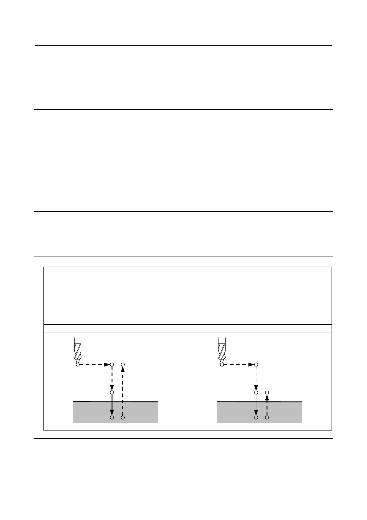
5.FUNCTIONS TO SIMPLIFY
B-63944EN-2/04 PROGRAMMING
PROGRAMMING
- Cancel
Do not specify a G code of the 01 group (G00 to G03) and G81 in a single block. Otherwise, G81 will be
canceled.
- Tool offset
In the canned cycle mode for drilling, tool offsets are ignored.
Example
M3 S2000 ; Cause the spindle to start rotating.
G90 G99 G81 X300. Y-250. Z-150. R-100. F120. ; Position, drill hole 1, then return to point R.
Y-550. ; Position, drill hole 2, then return to point R.
Y-750. ; Position, drill hole 3, then return to point R.
X1000. ; Position, drill hole 4, then return to point R.
Y-550. ; Position, drill hole 5, then return to point R.
G98 Y-750. ; Position, drill hole 6, then return to the initial level.
G80 G28 G91 X0 Y0 Z0 ; Return to the reference position
M5 ; Cause the spindle to stop rotating.
5.1.5 Drilling Cycle Counter Boring Cycle (G82)
This cycle is used for normal drilling.
Cutting feed is performed to the bottom of the hole. At the bottom, a dwell is performed, then the tool is
retracted in rapid traverse.
This cycle is used to drill holes more accurately with respect to depth.
Format
G82 X_ Y_ Z_ R_ P_ F_ K_ ;
X_ Y_ : Hole position data
Z_ : The distance from point R to the bottom of the hole
R_ : The distance from the initial level to point R level
P_ : Dwell time at the bottom of a hole
F_ : Cutting feed rate
K_ : Number of repeats (if required)
G82 (G98) G82 (G99)
Initial level
Point R
Point R
Point R level
P
Point Z
Explanation
- Operations
After positioning along the X- and Y-axes, rapid traverse is performed to point R.
Drilling is then performed from point R to point Z.
- 53 -
P
Point Z
Page 70

5. FUNCTIONS TO SIMPLIFY
PROGRAMMING
PROGRAMMING B-63944EN-2/04
When the bottom of the hole has been reached, a dwell is performed. The tool is then retracted in rapid
traverse.
- Spindle rotation
Before specifying G82, use an auxiliary function (M code) to rotate the spindle.
- Auxiliary function
When the G82 command and an M code are specified in the same block, the M code is executed at the
time of the first positioning operation. When K is used to specify the number of repeats, the M code is
executed for the first hole only; for the second and subsequent holes, the M code is not executed.
- Tool length compensation
When a tool length compensation (G43, G44, or G49) is specified in the canned cycle for drilling, the
offset is applied after the time of positioning to point R.
Limitation
- Axis switching
Before the drilling axis can be changed, the canned cycle for drilling must be canceled.
- Drilling
In a block that does not contain X, Y, Z, R, or any other axes, drilling is not performed.
- P
Specify P in blocks that perform drilling. If it is specified in a block that does not perform drilling, it
cannot be stored as modal data.
- Cancel
Do not specify a G code of the 01 group (G00 to G03) and G82 in a single block. Otherwise, G82 will be
canceled.
- Tool offset
In the canned cycle mode for drilling, tool offsets are ignored.
Example
M3 S2000 ; Cause the spindle to start rotating.
G90 G99 G82 X300. Y-250. Z-150. R-100. P1000 F120. ;
Position, drill hole 1, and dwell for 1 s at the bottom of the hole, then
return to point R.
Y-550. ; Position, drill hole 2, then return to point R.
Y-750. ; Position, drill hole 3, then return to point R.
X1000. ; Position, drill hole 4, then return to point R.
Y-550. ; Position, drill hole 5, then return to point R.
G98 Y-750. ; Position, drill hole 6, then return to the initial level.
G80 G28 G91 X0 Y0 Z0 ; Return to the reference position
M5 ; Cause the spindle to stop rotating.
- 54 -
Page 71

5.FUNCTIONS TO SIMPLIFY
B-63944EN-2/04 PROGRAMMING
PROGRAMMING
5.1.6 Peck Drilling Cycle (G83)
This cycle performs peck drilling.
It performs intermittent cutting feed to the bottom of a hole while removing shavings from the hole.
Format
G83 X_ Y_ Z_ R_ Q_ F_ K_ ;
X_ Y_ : Hole position data
Z_ : The distance from point R to the bottom of the hole
R_ : The distance from the initial level to point R level
Q_ : Depth of cut for each cutting feed
F_ : Cutting feedrate
K_ : Number of repeats (if required)
G83 (G98) G83 (G99)
Initial level
Point R
q
q
q
d
d
Point Z
Point R
q
q
q
Point R level
d
d
Point Z
Explanation
- Operations
Q represents the depth of cut for each cutting feed. It must always be specified as an incremental value.
In the second and subsequent cutting feeds, rapid traverse is performed up to a d point just before where
the last drilling ended, and cutting feed is performed again. d is set in parameter No.5115.
Be sure to specify a positive value in Q. Negative values are ignored.
- Spindle rotation
Before specifying G83, use an auxiliary function (M code) to rotate the spindle.
- Auxiliary function
When the G83 command and an M code are specified in the same block, the M code is executed at the
time of the first positioning operation. When K is used to specify the number of repeats, the M code is
executed for the first hole only; for the second and subsequent holes, the M code is not executed.
- Tool length compensation
When a tool length compensation (G43, G44, or G49) is specified in the canned cycle for drilling, the
offset is applied after the time of positioning to point R.
Limitation
- Axis switching
Before the drilling axis can be changed, the canned cycle for drilling must be canceled.
- 55 -
Page 72

5. FUNCTIONS TO SIMPLIFY
PROGRAMMING
PROGRAMMING B-63944EN-2/04
- Drilling
In a block that does not contain X, Y, Z, R, or any other axes, drilling is not performed.
- Q
Specify Q in blocks that perform drilling. If they are specified in a block that does not perform drilling,
they cannot be stored as modal data.
- Cancel
Do not specify a G code of the 01 group (G00 to G03) and G83 in a single block. Otherwise, G83 will be
canceled.
- Tool offset
In the canned cycle mode for drilling, tool offsets are ignored.
Example
M3 S2000 ; Cause the spindle to start rotating.
G90 G99 G83 X300. Y-250. Z-150. R-100. Q1000000000000005. F120. ;
Position, drill hole 1, then return to point R.
Y-550. ; Position, drill hole 2, then return to point R.
Y-750. ; Position, drill hole 3, then return to point R.
X1000. ; Position, drill hole 4, then return to point R.
Y-550. ; Position, drill hole 5, then return to point R.
G98 Y-750. ; Position, drill hole 6, then return to the initial level.
G80 G28 G91 X0 Y0 Z0 ; Return to the reference position
M5 ; Cause the spindle to stop rotating.
- 56 -
Page 73

5.FUNCTIONS TO SIMPLIFY
q
B-63944EN-2/04 PROGRAMMING
PROGRAMMING
5.1.7 Small-Hole Peck Drilling Cycle (G83)
An arbor with the overload torque detection function is used to retract the tool when the overload torque
detection signal (skip signal) is detected during drilling. Drilling is resumed after the spindle speed and
cutting feedrate are changed. These steps are repeated in this peck drilling cycle.
The mode for the small–hole peck drilling cycle is selected when the M code in parameter 5163 is
specified. The cycle can be started by specifying G83 in this mode. This mode is canceled when G80 is
specified or when a reset occurs.
Format
G83 X_ Y_ Z_ R_ Q_ F_ I_ K_ P_ ;
X_ Y_ : Hole position data
Z_ : Distance from point R to the bottom of the hole
R_ : Distance from the initial level to point R
Q_ : Depth of each cut
F_ : Cutting feedrate
I_ : Forward or backward traveling speed (same format as F above)
(If this is omitted, the values in parameters Nos. 5172 and 5173 are assumed as
defaults.)
K_ : Number of times the operation is repeated (if required)
P_ : Dwell time at the bottom of the hole
(If this is omitted, P0 is assumed as the default.)
G83 (G98) G83 (G99)
Initial level
Point R
Point R
q
q
Δ
Δ
Overload torque
Dwell
Δ: Initial clearance when the tool is retracted to point R and the clearance from the bottom of the hole in the second or
subsequent drilling (parameter 5174)
q: Depth of each cut
Path along which the tool travels at the rapid traverse rate
Path along which the tool travels at the programmed cutting feedrate
Path along which the tool travels at the forward or backward rate during the cycle specified with parameters
()
Point Z
Overload tor
Δ
ue
Point R level
Δ
Point Z
Dwell
Explanations
- Component operations of the cycle
* X- and Y-axis positioning
* Positioning at point R along the Z-axis
- 57 -
Page 74

5. FUNCTIONS TO SIMPLIFY
PROGRAMMING
PROGRAMMING B-63944EN-2/04
* Cutting along the Z-axis (first time, depth of cut Q, incremental)
Retracting (bottom of hole → minimum clearance ∆, incremental)
Retraction (bottom of hole +Δ → to point R, absolute)
Forwarding (point R → to point with hole bottom + clearance ∆, absolute)
Cutting (second and subsequent times, cut of depth Q + ∆, incremental)
* Dwell
* Return to point R along the Z-axis (or initial point) = end of cycle
Acceleration/deceleration during advancing and retraction is controlled according to the cutting feed
acceleration/deceleration time constant.
When retraction is performed, the position is checked at point R.
- Specifying an M code
When the M code in parameter 5163 is specified, the system enters the mode for the small–hole peck
drilling cycle.
This M code does not wait for FIN. Care must be taken when this M code is specified with another M
code in the same block.
(Example) M03 M ; → Waits for FIN.
M M03 ; → Does not wait for FIN.
- Specifying a G code
When G83 is specified in the mode for the small-hole peck drilling cycle, the cycle is started.
This continuous–state G code remains unchanged until another canned cycle is specified or until the G
code for canceling the canned cycle is specified. This eliminates the need for specifying drilling data in
each block when identical drilling is repeated.
- Signal indicating that the cycle is in progress
In this cycle mode, the small-diameter peck drilling cycle in progress signal is set to "1" at the start of
point R positioning on the axis in the drilling direction after G83 is specified and positioning is performed
to the specified hold position. This signal is set to "0" if another canned cycle is specified or if this mode
is canceled with G80, a reset, or an emergency stop. For details, refer to the manual of the machine tool
builder.
- Overload torque detection signal
A skip signal is used as the overload torque detection signal. The skip signal is effective while the tool is
advancing or drilling and the tool tip is between points R and Z. (The signal causes a retraction). For
details, refer to the manual of the machine tool builder.
NOTE
When receiving overload torque detect signal while the tool is advancing, the tool will be
retracted (clearance Δ and to the point R), then advanced to the same target point as
previous advancing.
- Changing the drilling conditions
In a single G83 cycle, drilling conditions are changed for each drilling operation (advance → drilling →
retraction). Bits 1 and 2 of parameter OLS, NOL No. 5160 can be specified to suppress the change in
drilling conditions.
1 Changing the cutting feedrate
The cutting feedrate programmed with the F code is changed for each of the second and subsequent
drilling operations. In parameters Nos.5166 and 5167, specify the respective rates of change applied
when the skip signal is detected and when it is not detected in the previous drilling operation.
- 58 -
Page 75

5.FUNCTIONS TO SIMPLIFY
B-63944EN-2/04 PROGRAMMING
Cutting feedrate = F × α
<First drilling> α=1.0
<Second or subsequent drilling>
α=α×β÷100, where β is the rate of change for each drilling operation
When the skip signal is detected during the previous drilling operation: β=b1% (parameter No.5166)
When the skip signal is not detected during the previous drilling operation: β=b2% (parameter
No.5167)
If the rate of change in cutting feedrate becomes smaller than the rate specified in parameter 5168,
the cutting feedrate is not changed.
The cutting feedrate can be increased up to the maximum cutting feedrate.
2 Changing the spindle speed
The spindle speed programmed with the S code is changed for each of the second and subsequent
advances. In parameters 5164 and 5165, specify the rates of change applied when the skip signal is
detected and when it is not detected in the previous drilling operation.
Spindle speed = S × γ
<First drilling> γ=1.0
<Second or subsequent drilling>
γ=γ×δ÷100, where δ is the rate of change for each drilling operation
When the skip signal is detected during the previous drilling operation: δ=d1% (parameter No.5164)
When the skip signal is not detected during the previous drilling operation: δ=d2% (parameter
No.5165)
When the cutting feedrate reaches the minimum rate, the spindle speed is not changed. The spindle
speed can be increased up to a value corresponding to the maximum value of S analog data.
PROGRAMMING
- Advance and retraction
Advancing and retraction of the tool are not executed in the same manner as rapid-traverse positioning.
Like cutting feed, the two operations are carried out as interpolated operations. Note that the tool life
management function excludes advancing and retraction from the calculation of the tool life.
- Specifying address I
The forward or backward traveling speed can be specified with address I in the same format as address F,
as shown below:
G83 I1000 ; (without decimal point)
G83 I1000. ; (with decimal point)
Both commands indicate a speed of 1000 mm/min.
Address I specified with G83 in the continuous-state mode continues to be valid until G80 is specified or
until a reset occurs.
NOTE
If address I is not specified and parameter No.5172 (for backword) or No.5173 (for
forword) is set to 0, the forword or backword travel speed is same as the cutting
feedrate specified by F.
- Functions that can be specified
In this canned cycle mode, the following functions can be specified:
• Hole position on the X-axis, Y-axis, and additional axis
• Operation and branch by custom macro
- 59 -
Page 76

5. FUNCTIONS TO SIMPLIFY
PROGRAMMING
PROGRAMMING B-63944EN-2/04
• Subprogram (hole position group, etc.) calling
• Switching between absolute and incremental modes
• Coordinate system rotation
• Scaling (This command will not affect depth of cut Q or small clearance Δ.)
• Dry run
• Feed hold
- Single block
When single-block operation is enabled, drilling is stopped after each retraction. Also, a single block stop
is performed by setting parameter SBC (No.5105 bit 0)
- Feedrate override
The feedrate override function works during cutting, retraction, and advancing in the cycle.
- Custom macro interface
The number of retractions made during cutting and the number of retractions made in response to the
overload signal received during cutting can be output to custom macro common variables (#100 to #149)
specified in parameters Nos.5170 and 5171. Parameters Nos.5170 and 5171 can specify variable numbers
within the range of #100 to #149.
Parameter No.5170: Specifies the number of the common variable to which the number of retractions
made during cutting is output.
Parameter No.5171: Specifies the number of the common variable to which the number of retractions
made in response to the overload signal received during cutting is output.
NOTE
The numbers of retraction output to common variables are cleared by G83 while
small-hole peck drilling cycle mode.
Limitation
- Subprogram call
In the canned cycle mode, specify the subprogram call command M98P_ in an independent block.
Example
M03 S_ ; Cause the spindle to start rotating.
M ; Specifies the small-hole peck drilling cycle mode.
G83 X_ Y_ Z_ R_ Q_ F_ I_ K_ P_ ; Specifies the small-hole peck drilling cycle.
X_ Y_ ; Drills at another position.
:
:
G80 ; Cancels the small-hole peck drilling cycle mode.
- 60 -
Page 77

5.FUNCTIONS TO SIMPLIFY
B-63944EN-2/04 PROGRAMMING
PROGRAMMING
5.1.8 Tapping Cycle (G84)
This cycle performs tapping.
In this tapping cycle, when the bottom of the hole has been reached, the spindle is rotated in the reverse
direction.
Format
G84 X_ Y_ Z_ R_ P_ F_ K_ ;
X_ Y_ : Hole position data
Z_ : The distance from point R to the bottom of the hole
R_ : The distance from the initial level to point R level
P_ : Dwell time
F_ : Cutting feedrate
K_ : Number of repents (if required)
G84 (G98) G84 (G99)
Initial level
Spindle
CW
P
Point R level
Point ZP
Spindle CCW
Point R
Spindle
CW
P
Point ZP
Spindle CCW
Point R
Explanation
- Operations
Tapping is performed by rotating the spindle clockwise. When the bottom of the hole has been reached,
the spindle is rotated in the reverse direction for retraction. This operation creates threads.
CAUTION
Feedrate overrides are ignored during tapping. A feed hold does not stop the
machine until the return operation is completed.
- Spindle rotation
Before specifying G84, use an auxiliary function (M code) to rotate the spindle.
If drilling is continuously performed with a small value specified for the distance between the hole
position and point R level or between the initial level and point R level, the normal spindle speed may not
be reached at the start of hole cutting operation. In this case, insert a dwell before each drilling operation
with G04 to delay the operation, without specifying the number of repeats for K. For some machines, the
above note may not be considered. Refer to the manual provided by the machine tool builder.
- Auxiliary function
When the G84 command and an M code are specified in the same block, the M code is executed at the
time of the first positioning operation. When the K is used to specify number of repeats, the M code is
executed for the first hole only; for the second and subsequent holes, the M code is not executed.
- 61 -
Page 78

5. FUNCTIONS TO SIMPLIFY
PROGRAMMING
PROGRAMMING B-63944EN-2/04
- Tool length compensation
When a tool length compensation (G43, G44, or G49) is specified in the canned cycle for drilling, the
offset is applied after the time of positioning to point R.
Limitation
- Axis switching
Before the drilling axis can be changed, the canned cycle for drilling must be canceled.
- Drilling
In a block that does not contain X, Y, Z, R, or any other axes, drilling is not performed.
- P
Specify P in blocks that perform drilling. If it is specified in a block that does not perform drilling, it
cannot be stored as modal data.
- Cancel
Do not specify a G code of the 01 group (G00 to G03) and G84 in a single block. Otherwise, G84 will be
canceled.
Example
M3 S100 ; Cause the spindle to start rotating.
G90 G99 G84 X300. Y-250. Z-150. R-120. P300 F120. ;
Position, drill hole 1, then return to point R.
Y-550. ; Position, drill hole 2, then return to point R.
Y-750. ; Position, drill hole 3, then return to point R.
X1000. ; Position, drill hole 4, then return to point R.
Y-550. ; Position, drill hole 5, then return to point R.
G98 Y-750. ; Position, drill hole 6, then return to the initial level.
G80 G28 G91 X0 Y0 Z0 ; Return to the reference position
M5 ; Cause the spindle to stop rotating.
- 62 -
Page 79

5.FUNCTIONS TO SIMPLIFY
B-63944EN-2/04 PROGRAMMING
PROGRAMMING
5.1.9 Boring Cycle (G85)
This cycle is used to bore a hole.
Format
G85 X_ Y_ Z_ R_ F_ K_ ;
X_ Y_ : Hole position data
Z_ : The distance from point R to the bottom of the hole
R_ : The distance from the initial level to point R level
F_ : Cutting feed rate
K_ : Number of repeats (if required)
G85 (G98) G85 (G99)
Initial level
Point R
Point Z
Point R
Point R level
Point Z
Explanation
- Operations
After positioning along the X- and Y- axes, rapid traverse is performed to point R.
Drilling is performed from point R to point Z.
When point Z has been reached, cutting feed is performed to return to point R.
- Spindle rotation
Before specifying G85, use an auxiliary function (M code) to rotate the spindle.
- Auxiliary function
When the G85 command and an M code are specified in the same block, the M code is executed at the
time of the first positioning operation. When K is used to specify the number of repeats, the M code is
executed for the first hole only; for the second and subsequent holes, the M code is not executed.
- Tool length compensation
When a tool length compensation (G43, G44, or G49) is specified in the canned cycle for drilling, the
offset is applied after the time of positioning to point R.
Limitation
- Axis switching
Before the drilling axis can be changed, the canned cycle for drilling must be canceled.
- Drilling
In a block that does not contain X, Y, Z, R, or any other axes, drilling is not performed.
- Cancel
Do not specify a G code of the 01 group (G00 to G03) and G85 in a single block. Otherwise, G85 will be
canceled.
- 63 -
Page 80

5. FUNCTIONS TO SIMPLIFY
PROGRAMMING
PROGRAMMING B-63944EN-2/04
- Tool offset
In the canned cycle mode for drilling, tool offsets are ignored.
Example
M3 S100 ; Cause the spindle to start rotating.
G90 G99 G85 X300. Y-250. Z-150. R-120. F120. ;
Position, drill hole 1, then return to point R.
Y-550. ; Position, drill hole 2, then return to point R.
Y-750. ; Position, drill hole 3, then return to point R.
X1000. ; Position, drill hole 4, then return to point R.
Y-550. ; Position, drill hole 5, then return to point R.
G98 Y-750. ; Position, drill hole 6, then return to the initial level.
G80 G28 G91 X0 Y0 Z0 ; Return to the reference position
M5 ; Cause the spindle to stop rotating.
5.1.10 Boring Cycle (G86)
This cycle is used to bore a hole.
Format
G86 X_ Y_ Z_ R_ F_ K_ ;
X_ Y_ : Hole position data
Z_ : The distance from point R to the bottom of the hole
R_ : The distance from the initial level to point R level
F_ : Cutting feed rate
K_ : Number of repeats (if required)
G86 (G98) G86 (G99)
Spindle CW
Initial level
Spindle CW
Point R
Point Z
Spindle stop
Point R
Point R level
Point Z
Spindle stop
Explanation
- Operations
After positioning along the X- and Y-axes, rapid traverse is performed to point R.
Drilling is performed from point R to point Z.
When the spindle is stopped at the bottom of the hole, the tool is retracted in rapid traverse.
- Spindle rotation
Before specifying G86, use an auxiliary function (M code) to rotate the spindle.
If drilling is continuously performed with a small value specified for the distance between the hole
position and point R level or between the initial level and point R level, the normal spindle speed may not
be reached at the start of hole cutting operation.
- 64 -
Page 81

5.FUNCTIONS TO SIMPLIFY
B-63944EN-2/04 PROGRAMMING
In this case, insert a dwell before each drilling operation with G04 to delay the operation, without
specifying the number of repeats for K. For some machines, the above note may not be considered. Refer
to the manual provided by the machine tool builder.
PROGRAMMING
- Auxiliary function
When the G86 command and an M code are specified in the same block, the M code is executed at the
time of the first positioning operation. When K is used to specify the number of repeats, the M code is
executed for the first hole only; for the second and subsequent holes, the M code is not executed.
- Tool length compensation
When a tool length compensation (G43, G44, or G49) is specified in the canned cycle for drilling, the
offset is applied after the time of positioning to point R.
Limitation
- Axis switching
Before the drilling axis can be changed, the canned cycle for drilling must be canceled.
- Drilling
In a block that does not contain X, Y, Z, R, or any other axes, drilling is not performed.
- Cancel
Do not specify a G code of the 01 group (G00 to G03) and G86 in a single block. Otherwise, G86 will be
canceled.
- Tool offset
In the canned cycle mode for drilling, tool offsets are ignored.
Example
M3 S2000 ; Cause the spindle to start rotating.
G90 G99 G86 X300. Y-250. Z-150. R-100. F120. ;
Position, drill hole 1, then return to point R.
Y-550. ; Position, drill hole 2, then return to point R.
Y-750. ; Position, drill hole 3, then return to point R.
X1000. ; Position, drill hole 4, then return to point R.
Y-550. ; Position, drill hole 5, then return to point R.
G98 Y-750. ; Position, drill hole 6, then return to the initial level.
G80 G28 G91 X0 Y0 Z0 ; Return to the reference position
M5 ; Cause the spindle to stop rotating.
- 65 -
Page 82

5. FUNCTIONS TO SIMPLIFY
PROGRAMMING
PROGRAMMING B-63944EN-2/04
5.1.11 Back Boring Cycle (G87)
This cycle performs accurate boring.
Format
G87 X_ Y_ Z_ R_ Q_ P_ F_ K_ ;
X_ Y_ : Hole position data
Z_ : The distance from point R to the bottom of the hole
R_ : The distance from the initial level to point R
Q_ : Shift amount at the bottom of a hole
P_ : Dwell time at the bottom of a hole
F_ : Cutting feed rate
K_ : Number of repeats (if required)
G87 (G98) G87 (G99)
Spindle orientation
Tool
Shift amount q
OSS
Spindle CW
OSS
P
Spindle CW
q
Initial
level
Not used
Point Z
Point R
Explanation
After positioning along the X- and Y-axes, the spindle is stopped at the fixed rotation position. The tool is
moved in the direction opposite to the tool nose, positioning (rapid traverse) is performed to the bottom of
the hole (point R).
The tool is then shifted in the direction of the tool nose and the spindle is rotated clockwise. Boring is
performed in the positive direction along the Z-axis until point Z is reached.
At point Z, the spindle is stopped at the fixed rotation position again, the tool is shifted in the direction
opposite to the tool nose, then the tool is returned to the initial level. The tool is then shifted in the
direction of the tool nose and the spindle is rotated clockwise to proceed to the next block operation.
- Spindle rotation
Before specifying G87, use an auxiliary function (M code) to rotate the spindle.
If drilling is continuously performed with a small value specified for the distance between the hole
position and point R level or between the initial level and point R level, the normal spindle speed may not
be reached at the start of hole cutting operation. In this case, insert a dwell before each drilling operation
with G04 to delay the operation, without specifying the number of repeats for K. For some machines, the
above note may not be considered. Refer to the manual provided by the machine tool builder.
- Auxiliary function
When the G87 command and an M code are specified in the same block, the M code is executed at the
time of the first positioning operation. When K is used to specify the number of repeats, the M code is
executed for the first hole only; for the second and subsequent holes, the M code is not executed.
- Tool length compensation
When a tool length compensation (G43, G44, or G49) is specified in the canned cycle for drilling, the
offset is applied after the time of positioning to point R.
- 66 -
Page 83

5.FUNCTIONS TO SIMPLIFY
B-63944EN-2/04 PROGRAMMING
PROGRAMMING
Limitation
- Axis switching
Before the drilling axis can be changed, the canned cycle for drilling must be canceled.
- Drilling
In a block that does not contain X, Y, Z, R, or any additional axes, drilling is not performed.
- P/Q
Be sure to specify a positive value in Q. If Q is specified with a negative value, the sign is ignored. Set
the direction of shift in the parameter No. 5148.
Specify P and Q in a block that performs drilling. If they are specified in a block that does not perform
drilling, they are not stored as modal data.
CAUTION
Q (shift at the bottom of a hole) is a modal value retained in canned cycles for
drilling. It must be specified carefully because it is also used as the depth of cut
for G73 and G83.
- Cancel
Do not specify a G code of the 01 group (G00 to G03) and G87 in a single block. Otherwise, G87 will be
canceled.
- Tool offset
In the canned cycle mode for drilling, tool offsets are ignored.
Example
M3 S500 ; Cause the spindle to start rotating.
G90 G87 X300. Y-250. Position, bore hole 1.
Z-150. R-120. Q5. Orient at the initial level, then shift by 5 mm.
P1000 F120. ; Stop at point Z for 1 s.
Y-550. ; Position, drill hole 2.
Y-750. ; Position, drill hole 3.
X1000. ; Position, drill hole 4.
Y-550. ; Position, drill hole 5.
Y-750. ; Position, drill hole 6
G80 G28 G91 X0 Y0 Z0 ; Return to the reference position
M5 ; Cause the spindle to stop rotating.
- 67 -
Page 84

5. FUNCTIONS TO SIMPLIFY
PROGRAMMING
PROGRAMMING B-63944EN-2/04
5.1.12 Boring Cycle (G88)
This cycle is used to bore a hole.
Format
G88 X_ Y_ Z_ R_ P_ F_ K_ ;
X_ Y_ : Hole position data
Z_ : The distance from point R to the bottom of the hole
R_ : The distance from the initial level to point R level
P_ : Dwell time at the bottom of a hole
F_ : Cutting feed rate
K_ : Number of repeats (if required)
G88 (G98) G88 (G99)
Spindle CW
Initial level
Spindle CW
Point R
Point Z
P
Spindle stop
after dwell
Point R
Point Z
P
Point R level
Spindle stop
after dwell
Explanation
- Operations
After positioning along the X- and Y-axes, rapid traverse is performed to point R. Boring is performed
from point R to point Z.
When boring is completed, a dwell is performed at the bottom of the hole, then the spindle is stopped and
enters the hold state. At this time, you can switch to the manual mode and move the tool manually. Any
manual operations are available; it is desirable to finally retract the tool from the hole for safety, though.
At the restart of machining in the DNC operation or memory mode, the tool returns to the initial level or
point R level according to G98 or G99 and the spindle rotates clockwise. Then, operation is restarted
according to the programmed commands in the next block.
- Spindle rotation
Before specifying G88, use an auxiliary function (M code) to rotate the spindle.
- Auxiliary function
When the G88 command and an M code are specified in the same block, the M code is executed at the
time of the first positioning operation. When K is used to specify the number of repeats, the M code is
executed for the first hole only; for the second and subsequent holes, the M code is not executed.
- Tool length compensation
When a tool length compensation (G43, G44, or G49) is specified in the canned cycle for drilling, the
offset is applied after the time of positioning to point R.
- 68 -
Page 85

5.FUNCTIONS TO SIMPLIFY
B-63944EN-2/04 PROGRAMMING
PROGRAMMING
Limitation
- Axis switching
Before the drilling axis can be changed, the canned cycle for drilling must be canceled.
- Drilling
In a block that does not contain X, Y, Z, R, or any other axes, drilling is not performed.
- P
Specify P in blocks that perform drilling. If it is specified in a block that does not perform drilling, it
cannot be stored as modal data.
- Cancel
Do not specify a G code of the 01 group (G00 to G03) and G88 in a single block. Otherwise, G88 will be
canceled.
- Tool offset
In the canned cycle mode for drilling, tool offsets are ignored.
Example
M3 S2000 ; Cause the spindle to start rotating.
G90 G99 G88 X300. Y-250. Z-150. R-100. P1000 F120. ;
Position, drill hole 1, return to point R then stop at the bottom of the hole
for 1 s.
Y-550. ; Position, drill hole 2, then return to point R.
Y-750. ; Position, drill hole 3, then return to point R.
X1000. ; Position, drill hole 4, then return to point R.
Y-550. ; Position, drill hole 5, then return to point R.
G98 Y-750. ; Position, drill hole 6, then return to the initial level.
G80 G28 G91 X0 Y0 Z0 ; Return to the reference position
M5 ; Cause the spindle to stop rotating.
- 69 -
Page 86

5. FUNCTIONS TO SIMPLIFY
PROGRAMMING
PROGRAMMING B-63944EN-2/04
5.1.13 Boring Cycle (G89)
This cycle is used to bore a hole.
Format
G89 X_ Y_ Z_ R_ P_ F_ K_ ;
X_ Y_ : Hole position data
Z_ : The distance from point R to the bottom of the hole
R_ : The distance from the initial level to point R level
P_ : Dwell time at the bottom of a hole
F_ : Cutting feed rate
K_ : Number of repeats (if required)
G89 (G98) G89 (G99)
Initial level
Point R
Point Z
P
Point R
Point R level
Point Z
P
Explanation
- Operations
This cycle is almost the same as G85. The difference is that this cycle performs a dwell at the bottom of
the hole.
- Spindle rotation
Before specifying G89, use an auxiliary function (M code) to rotate the spindle.
- Auxiliary function
When the G89 command and an M code are specified in the same block, the M code is executed at the
time of the first positioning operation. When K is used to specify the number of repeats, the M code is
executed for the first hole only; for the second and subsequent holes, the M code is not executed.
- Tool length compensation
When a tool length compensation (G43, G44, or G49) is specified in the canned cycle for drilling, the
offset is applied after the time of positioning to point R.
Limitation
- Axis switching
Before the drilling axis can be changed, the canned cycle for drilling must be canceled.
- Drilling
In a block that does not contain X, Y, Z, R, or any other axes, drilling is not performed.
- P
Specify P in blocks that perform drilling. If it is specified in a block that does not perform drilling, it
cannot be stored as modal data.
- 70 -
Page 87

5.FUNCTIONS TO SIMPLIFY
B-63944EN-2/04 PROGRAMMING
PROGRAMMING
- Cancel
Do not specify a G code of the 01 group (G00 to G03) and G89 in a single block. Otherwise, G89 will be
canceled.
- Tool offset
In the canned cycle mode for drilling, tool offsets are ignored.
Example
M3 S100 ; Cause the spindle to start rotating.
G90 G99 G89 X300. Y-250. Z-150. R-120. P1000 F120. ;
Position, drill hole 1, return to point R then stop at the bottom of the hole
for 1 s.
Y-550. ; Position, drill hole 2, then return to point R.
Y-750. ; Position, drill hole 3, then return to point R.
X1000. ; Position, drill hole 4, then return to point R.
Y-550. ; Position, drill hole 5, then return to point R.
G98 Y-750. ; Position, drill hole 6, then return to the initial level.
G80 G28 G91 X0 Y0 Z0 ; Return to the reference position
M5 ; Cause the spindle to stop rotating.
5.1.14 Canned Cycle Cancel for Drilling (G80)
G80 cancels canned cycles for drilling.
Format
G80 ;
Explanation
All canned cycles for drilling are canceled to perform normal operation. Point R and point Z are cleared.
Other drilling data is also canceled (cleared).
Example
M3 S100 ; Cause the spindle to start rotating.
G90 G99 G88 X300. Y-250. Z-150. R-120. F120. ;
Position, drill hole 1, then return to point R.
Y-550. ; Position, drill hole 2, then return to point R.
Y-750. ; Position, drill hole 3, then return to point R.
X1000. ; Position, drill hole 4, then return to point R.
Y-550. ; Position, drill hole 5, then return to point R.
G98 Y-750. ; Position, drill hole 6, then return to the initial level.
G80 G28 G91 X0 Y0 Z0 ; Return to the reference position, canned cycle cancel
M5 ; Cause the spindle to stop rotating.
- 71 -
Page 88

5. FUNCTIONS TO SIMPLIFY
PROGRAMMING
PROGRAMMING B-63944EN-2/04
5.1.15 Example for Using Canned Cycles for Drilling
Offset value +200.0 is set in offset No.11, +190.0 is set in offset No.15, and +150.0 is set in offset No.31
Program example
;
N001 G92 X0 Y0 Z0; Coordinate setting at reference position
N002 G90 G00 Z250.0 T11 M6; Tool change
N003 G43 Z0 H11; Initial level, tool length compensation
N004 S30 M3; Spindle start
N005 G99 G81 X400.0 Y-350.0 Z-153.0 R-97.0 F120; Positioning, then #1 drilling
N006 Y-550.0; Positioning, then #2 drilling and point R level return
N007 G98 Y-750.0; Positioning, then #3 drilling and initial level return
N008 G99 X1200.0; Positioning, then #4 drilling and point R level return
N009 Y-550.0; Positioning, then #5 drilling and point R level return
N010 G98 Y-350.0; Positioning, then #6 drilling and initial level return
N011 G00 X0 Y0 M5; Reference position return, spindle stop
N012 G49 Z250.0 T15 M6; Tool length compensation cancel, tool change
N013 G43 Z0 H15; Initial level, tool length compensation
N014 S20 M3; Spindle start
N015 G99 G82 X550.0 Y-450.0 Z-130.0 R-97.0 P300 F70 ; Positioning, then #7 drilling, point R level return
N016 G98 Y-650.0; Positioning, then #8 drilling, initial level return
N017 G99 X1050.0; Positioning, then #9 drilling, point R level return
N018 G98 Y-450.0; Positioning, then #10 drilling, initial level return
N019 G00 X0 Y0 M5; Reference position return, spindle stop
N020 G49 Z250.0 T31 M6; Tool length compensation cancel, tool change
N021 G43 Z0 H31; Initial level, tool length compensation
N022 S10 M3; Spindle start
N023 G85 G99 X800.0 Y-350.0 Z-153.0 R47.0 F50; Positioning, then #11 drilling, point R level return
N024 G91 Y-200.0 K2; Positioning, then #12, 13 drilling, point R level
return
N025 G28 X0 Y0 M5; Reference position return, spindle stop
N026 G49 Z0; Tool length compensation cancel
N027 M0; Program stop
- 72 -
Page 89

5.FUNCTIONS TO SIMPLIFY
B-63944EN-2/04 PROGRAMMING
Program using tool length offset and canned cycles
Reference position
350
PROGRAMMING
#1 #11
100
100
100
Y
100
X
400 150 250 250 150
#1 to 6 Drilling of a 10 mm diameter hole
#7 to 10 Drilling of a 20 mm diameter hole
#11 to 13 Boring of a 95 mm diameter hole (depth 50 mm)
Z
X
Retract position
250
50
50
30
20
T 11 T 15 T 31
#2
#3
#7
#8
200
#12
200
#13
#6
#10
#5
#9
#4
Initial level
190200 150
Fig. 5.1.15 (a) Example for using canned cycles for drilling
- 73 -
Page 90

5. FUNCTIONS TO SIMPLIFY
PROGRAMMING
PROGRAMMING B-63944EN-2/04
5.2 RIGID TAPPING
The tapping cycle (G84) and left-handed tapping cycle (G74) may be performed in standard mode or rigid
tapping mode.
In standard mode, the spindle is rotated and stopped along with a movement along the tapping axis using
auxiliary functions M03 (rotating the spindle clockwise), M04 (rotating the spindle counterclockwise),
and M05 (stopping the spindle) to perform tapping.
In rigid mode, tapping is performed by controlling the spindle motor as if it were a servo motor and by
interpolating between the tapping axis and spindle.
When tapping is performed in rigid mode, the spindle rotates one turn every time a certain feed (thread
lead) which takes place along the tapping axis. This operation does not vary even during acceleration or
deceleration.
Rigid mode eliminates the need to use a floating tap required in the standard tapping mode, thus allowing
faster and more precise tapping.
5.2.1 Rigid Tapping (G84)
When the spindle motor is controlled in rigid mode as if it were a servo motor, a tapping cycle can be
sped up.
Format
G84 X_ Y_ Z_ R_ P_ F_ K_ ;
X_ Y_ : Hole position data
Z_ : The distance from point R to the bottom of the hole and the position of the bottom of
the hole
R_ : The distance from the initial level to point R level
P_ : Dwell time at the bottom of the hole and at point R when a return is made
F_ : Cutting feedrate
K_ : Number of repeats (if required)
G84.2 X_ Y_ Z_ R_ P_ F_ L_ ;
(Series 15 format)
L_ : Number of repeats (if required)
G84 (G98) G84 (G99)
Spindle stop
Initial level
Operation 1
Operation 2
Spindle CW
Point R
Operation 3
Spindle stop Spindle CCW
Operation 4
Operation 6
P
P
Spindle
stop
Point R level
Operation 5
Point Z
Spindle CW
Spindle stop Spindle CCW
Spindle stop
Point R
Spindle stop
P
Point R level
Point Z
P
- 74 -
Page 91

5.FUNCTIONS TO SIMPLIFY
B-63944EN-2/04 PROGRAMMING
PROGRAMMING
Explanation
After positioning along the X- and Y-axes, rapid traverse is performed to point R.
Tapping is performed from point R to point Z. When tapping is completed, the spindle is stopped and a
dwell is performed. The spindle is then rotated in the reverse direction, the tool is retracted to point R,
then the spindle is stopped. Rapid traverse to initial level is then performed.
While tapping is being performed, the feedrate override and spindle override are assumed to be 100%.
Feedrate override can be enabled by setting, however.
- Rigid mode
Rigid mode can be specified using any of the following methods:
• Specify M29 S***** before a tapping command.
• Specify M29 S***** in a block which contains a tapping command.
• Specify G84 for rigid tapping (bit 0 (G84) of parameter No. 5200 set to 1).
- Thread lead
In feed-per-minute mode, the thread lead is obtained from the expression, feedrate ÷ spindle speed. In
feed-per-revolution mode, the thread lead equals the feedrate speed.
- Tool length compensation
If a tool length compensation (G43, G44, or G49) is specified in the canned cycle, the offset is applied at
the time of positioning to point R.
- Series 15 format command
Rigid tapping can be performed using Series 15 format commands. The rigid tapping sequence (including
data transfer to and from the PMC), Limitation, and the like are the same as described in this chapter.
- Acceleration/deceleration after interpolation
Linear or bell-shaped acceleration/deceleration can be applied.
- Look-ahead acceleration/deceleration before interpolation
Look-ahead acceleration/deceleration before interpolation is invalid.
- Override
Various types of override functions are invalid. The following override functions can be enabled by
setting corresponding parameters:
• Extraction override
• Override signal
Details are given later.
- Dry run
Dry run can be executed also in G84 (G74). When dry run is executed at the feedrate for the drilling axis
in G84 (G74), tapping is performed according to the feedrate. Note that the spindle speed becomes faster
at a higher dry run feedrate.
- Machine lock
Machine lock can be executed also in G84 (G74).
When G84 (G74) is executed in the machine lock state, the tool does not move along the drilling axis.
Therefore, the spindle does not also rotate.
- Reset
When a reset is performed during rigid tapping, the rigid tapping mode is canceled and the spindle motor
enters the normal mode. Note that the G84 (G74) mode is not canceled in this case when bit 6 (CLR) of
parameter No. 3402 is set.
- 75 -
Page 92

5. FUNCTIONS TO SIMPLIFY
PROGRAMMING
PROGRAMMING B-63944EN-2/04
- Interlock
Interlock can also be applied in G84 (G74).
- Feed hold and single block
When bit 6 (FHD) of parameter No. 5200 is set to 0, feed hold and single block are invalid in the G84
(G74) mode. When this bit is set to 1, they are valid.
- Manual feed
For rigid tapping by manual handle feed, see the section "Rigid Tapping by Manual Handle."
With other manual operations, rigid tapping cannot be performed.
- Backlash compensation
In the rigid tapping mode, backlash compensation is applied to compensate the lost motion when the
spindle rotates clockwise or counterclockwise. Set the amount of backlash in parameters Nos. 5321 to
5324.
Along the drilling axis, backlash compensation has been applied.
Limitation
- Axis switching
Before the drilling axis can be changed, the canned cycle must be canceled. If the drilling axis is changed
in rigid mode, alarm PS0206 is issued.
- S command
• If a speed higher than the maximum speed for the gear being used is specified, alarm PS0200 is
issued.
• When the rigid tapping canned cycle is cancelled, the S command used for rigid tapping is cleared to
S0.
- Distribution amount for the spindle
The maximum distribution amount is as follows (displayed on diagnosis data No. 451):
• For a serial spindle: 32,767 pulses per 8 ms
This amount is changed according to the gear ratio setting for the position coder or rigid tapping
command. If a setting is made to exceed the upper limit, alarm PS0202 is issued.
- F command
If a value exceeding the upper limit of cutting feedrate is specified, alarm PS0011 is issued.
- Unit of F command
Metric input Inch input Remarks
G94 1 mm/min 0.01 inch/min Decimal point programming allowed
G95 0.01 mm/rev 0.0001 inch/rev Decimal point programming allowed
- M29
If an S command and axis movement are specified between M29 and G84, alarm PS0203 is issued. If
M29 is specified in a tapping cycle, alarm PS0204 is issued.
- P
Specify P in a block that performs drilling. If P is specified in a non-drilling block, it is not stored as
modal data.
- 76 -
Page 93

5.FUNCTIONS TO SIMPLIFY
B-63944EN-2/04 PROGRAMMING
PROGRAMMING
- Cancel
Do not specify a G code of the 01 group (G00 to G03 or G60 (when the bit 0 (MDL) of parameter No.
5431 is set to 1)) and G74 in a single block. Otherwise, G74 will be canceled.
- Tool offset
In the canned cycle mode, tool offsets are ignored.
- Program restart
A program cannot be restarted during rigid tapping.
- Subprogram call
In the canned cycle mode, specify the subprogram call command M98P_ in an independent block.
Example
Z-axis feedrate 1000 mm/min
Spindle speed 1000 min
Thread lead 1.0 mm
<Programming of feed per minute>
G94; Specify a feed-per-minute command.
G00 X120.0 Y100.0 ; Positioning
M29 S1000 ; Rigid mode specification
G84 Z-100.0 R-20.0 F1000 ; Rigid tapping
<Programming of feed per revolution>
G95 ; Specify a feed-per-revolution command.
G00 X120.0 Y100.0 ; Positioning
M29 S1000 ; Rigid mode specification
G84 Z-100.0 R-20.0 F1.0 ; Rigid tapping
-1
- 77 -
Page 94

5. FUNCTIONS TO SIMPLIFY
PROGRAMMING
PROGRAMMING B-63944EN-2/04
5.2.2 Left-Handed Rigid Tapping Cycle (G74)
When the spindle motor is controlled in rigid mode as if it were a servo motor, tapping cycles can be
speed up.
Format
G74 X_ Y_ Z_ R_ P_ F_ K_ ;
X_ Y_ : Hole position data
Z_ : The distance from point R to the bottom of the hole and the position of the bottom of
the hole
R_ : The distance from the initial level to point R level
P_ : Dwell time at the bottom of the hole and at point R when return is made.
F_ : Cutting feedrate
K_ : Number of repeats (if required)
G84.3 X_ Y_ Z_ R_ P_ F_ L_ ;
(Series 15 format)
L_ : Number of repeats (if required)
G74 (G98) G74 (G99)
Spindle stop
Initial level
Operation 1
Operation 2
Spindle CCW
Point R
Operation 3
Spindle stop Spindle CW
Operation 4
Operation 6
P
Point R level
Operation 5
Point Z
P
Spindle
stop
Spindle CCW
Spindle stop
Spindle stop
Point R
P
Spindle stop
P
Point R level
Point Z
Spindle CW
Explanation
After positioning along the X- and Y-axes, rapid traverse is performed to point R.
Tapping is performed from point R to point Z. When tapping is completed, the spindle is stopped and a
dwell is performed. The spindle is then rotated in the normal direction, the tool is retracted to point R,
then the spindle is stopped. Rapid traverse to initial level is then performed.
While tapping is being performed, the feedrate override and spindle override are assumed to be 100%.
Feedrate override can be enabled by setting, however.
- Rigid mode
Rigid mode can be specified using any of the following methods:
• Specify M29 S***** before a tapping command.
• Specify M29 S***** in a block which contains a tapping command.
• Specify G74 for rigid tapping. (bit 0 (G84) of parameter No. 5200 set to1).
- Thread lead
In feed-per-minute mode, the thread lead is obtained from the expression, feedrate ÷ spindle speed. In
feed-per-revolution mode, the thread lead equals the feedrate.
- 78 -
Page 95

5.FUNCTIONS TO SIMPLIFY
B-63944EN-2/04 PROGRAMMING
PROGRAMMING
- Tool length compensation
If a tool length compensation (G43, G44, or G49) is specified in the canned cycle, the offset is applied at
the time of positioning to point R.
- Series 15 format command
Rigid tapping can be performed using Series 15 format commands. The rigid tapping sequence (including
data transfer to and from the PMC), Limitation, and the like are the same as described in this chapter.
- Acceleration/deceleration after interpolation
Linear or bell-shaped acceleration/deceleration can be applied.
- Look-ahead acceleration/deceleration before interpolation
Look-ahead acceleration/deceleration before interpolation is invalid.
- Override
Various types of override functions are invalid. The following override functions can be enabled by
setting corresponding parameters:
• Extraction override
• Override signal
Details are given later.
- Dry run
Dry run can be executed also in G84 (G74). When dry run is executed at the feedrate for the drilling axis
in G84 (G74), tapping is performed according to the feedrate. Note that the spindle speed becomes faster
at a higher dry run feedrate.
- Machine lock
Machine lock can be executed also in G84 (G74).
When G84 (G74) is executed in the machine lock state, the tool does not move along the drilling axis.
Therefore, the spindle does not also rotate.
- Reset
When a reset is performed during rigid tapping, the rigid tapping mode is canceled and the spindle motor
enters the normal mode. Note that the G84 (G74) mode is not canceled in this case when bit 6 (CLR) of
parameter No. 3402 is set.
- Interlock
Interlock can also be applied in G84 (G74).
- Feed hold and single block
When bit 6 (FHD) of parameter No. 5200 is set to 0, feed hold and single block are invalid in the G84
(G74) mode. When this bit is set to 1, they are valid.
- Manual feed
For rigid tapping by manual handle feed, see the section "Rigid Tapping by Manual Handle."
With other manual operations, rigid tapping cannot be performed.
- Backlash compensation
In the rigid tapping mode, backlash compensation is applied to compensate the lost motion when the
spindle rotates clockwise or counterclockwise. Set the amount of backlash in parameters Nos. 5321 to
5324.
Along the drilling axis, backlash compensation has been applied.
- 79 -
Page 96

5. FUNCTIONS TO SIMPLIFY
PROGRAMMING
PROGRAMMING B-63944EN-2/04
Limitation
- Axis switching
Before the drilling axis can be changed, the canned cycle must be canceled. If the drilling axis is changed
in rigid mode, alarm PS0206 is issued.
- S command
• Specifying a rotation speed exceeding the maximum speed for the gear used causes alarm PS0200.
• When the rigid tapping canned cycle is cancelled, the S command used for rigid tapping is cleared to
S0.
- Distribution amount for the spindle
The maximum distribution amount is as follows (displayed on diagnosis data No. 451):
• For a serial spindle: 32,767 pulses per 8 ms
This amount is changed according to the gear ratio setting for the position coder or rigid tapping
command. If a setting is made to exceed the upper limit, alarm PS0202 is issued.
- F command
Specifying a value that exceeds the upper limit of cutting feedrate causes alarm PS0011.
- Unit of F command
Metric input Inch input Remarks
G94 1 mm/min 0.01 inch/min Decimal point programming allowed
G95 0.01 mm/rev 0.0001 inch/rev Decimal point programming allowed
- M29
Specifying an S command or axis movement between M29 and G84 causes alarm PS0203.
Then, specifying M29 in the tapping cycle causes alarm PS0204.
- P
Specify P in a block that performs drilling. If P is specified in a non-drilling block, it is not stored as
modal data.
- Cancel
Do not specify a G code of the 01 group (G00 to G03 or G60 (when the bit 0 (MDL) of parameter No.
5431 is set to 1)) and G74 in a single block. Otherwise, G74 will be canceled.
- Tool offset
In the canned cycle mode, tool offsets are ignored.
- Subprogram call
In the canned cycle mode, specify the subprogram call command M98P_ in an independent block.
Example
Z-axis feedrate 1000 mm/min
Spindle speed 1000 min
Thread lead 1.0 mm
<Programming for feed per minute>
G94 ; Specify a feed-per-minute command.
G00 X120.0 Y100.0 ; Positioning
M29 S1000 ; Rigid mode specification
G74 Z-100.0 R-20.0 F1000 ; Rigid tapping
<Programming for feed per revolution>
G95 ; Specify a feed-per-revolution command.
-1
- 80 -
Page 97

5.FUNCTIONS TO SIMPLIFY
B-63944EN-2/04 PROGRAMMING
G00 X120.0 Y100.0 ; Positioning
M29 S1000 ; Rigid mode specification
G74 Z-100.0 R-20.0 F1.0 ; Rigid tapping
PROGRAMMING
- 81 -
Page 98

5. FUNCTIONS TO SIMPLIFY
PROGRAMMING
PROGRAMMING B-63944EN-2/04
5.2.3 Peck Rigid Tapping Cycle (G84 or G74)
Tapping a deep hole in rigid tapping mode may be difficult due to chips sticking to the tool or increased
cutting resistance. In such cases, the peck rigid tapping cycle is useful.
In this cycle, cutting is performed several times until the bottom of the hole is reached. Two peck tapping
cycles are available: High-speed peck tapping cycle and standard peck tapping cycle. These cycles are
selected using the PCP bit (bit 5) of parameter 5200.
Format
G84 (or G74) X_ Y_ Z_ R_ P_ Q_ F_ K_ ;
X_ Y_ : Hole position data
Z_ : The distance from point R to the bottom of the hole
and the position of the bottom of the hole
R_ : The distance from the initial level to point R level
P_ : Dwell time at the bottom of the hole and at point R
when a return is made
Q_ : Depth of cut for each cutting feed
F_ : The cutting feedrate
K_ : Number of repeats (if required)
G84.2 (or G84.3) X_ Y_ Z_ R_ P_ Q_ F_ L_ ;
(Series 15 format)
L_ : Number of repeats (if required)
G84, G74 (G98) G84, G74 (G99)
• High-speed peck tapping cycle (Bit
5 (PCP) of parameter No. 5200=0)
<1> The tool operates at a normal
cutting feedrate. The normal
time constant is used.
<2> Retraction can be overridden.
The retraction time
constant is used.
Point R
q
q
d = retraction distance
Point R le v e l
<1>
<2>
d
Initial lev e l
d
Point R
q
q
<1>
Point R le ve l
<2>
d
d
• Peck tapping cycle
(Bit 5 (PCP) of parameter No.
5200=1)
<1> The tool operates at a normal
cutting feedrate. The normal
time constant is used.
<2> Retraction can be overridden.
The retraction time constant is
used.
<3> Retraction can be overridden.
The normal time constant is
used.
q
Point R
q
q
q
Point Z
d = cutting start distance
Initial level
Point R level
<2>
<3>
d
Point Z
<1>
- 82 -
q
<3>
<2>
Point Z
Point R level
d
d
Point Z
Point R
q
d
q
q
<1>
Page 99

5.FUNCTIONS TO SIMPLIFY
B-63944EN-2/04 PROGRAMMING
PROGRAMMING
Explanation
- High-speed peck tapping cycle
After positioning along the X- and Y-axes, rapid traverse is performed to point R. From point R, cutting
is performed with depth Q (depth of cut for each cutting feed), then the tool is retracted by distance d. The
bit 4 (DOV) of parameter No. 5200 specifies whether retraction can be overridden or not. When point Z
has been reached, the spindle is stopped, then rotated in the reverse direction for retraction.
Set the retraction distance, d, in parameter 5213.
- Peck tapping cycle
After positioning along the X- and Y-axes, rapid traverse is performed to point R level. From point R,
cutting is performed with depth Q (depth of cut for each cutting feed), then a return is performed to point
R. The bit 4 (DOV) of parameter No. 5200 specifies whether the retraction can be overridden or not. The
moving of cutting feedrate F is performed from point R to a position distance d from the end point of the
last cutting, which is where cutting is restarted. For this moving of cutting feedrate F, the specification of
the bit 4 (DOV) of parameter No. 5200 is also valid. When point Z has been reached, the spindle is
stopped, then rotated in the reverse direction for retraction.
Set d (distance to the point at which cutting is started) in parameter No. 5213.
- Acceleration/deceleration after interpolation
Linear or bell-shaped acceleration/deceleration can be applied.
- Look-ahead acceleration/deceleration before interpolation
Look-ahead acceleration/deceleration before interpolation is invalid.
- Override
Various types of override functions are invalid. The following override functions can be enabled by
setting corresponding parameters:
• Extraction override
• Override signal
Details are given later.
- Dry run
Dry run can be executed also in G84 (G74). When dry run is executed at the feedrate for the drilling axis
in G84 (G74), tapping is performed according to the feedrate. Note that the spindle speed becomes faster
at a higher dry run feedrate.
- Machine lock
Machine lock can be executed also in G84 (G74).
When G84 (G74) is executed in the machine lock state, the tool does not move along the drilling axis.
Therefore, the spindle does not also rotate.
- Reset
When a reset is performed during rigid tapping, the rigid tapping mode is canceled and the spindle motor
enters the normal mode. Note that the G84 (G74) mode is not canceled in this case when bit 6 (CLR) of
parameter No. 3402 is set.
- Interlock
Interlock can also be applied in G84 (G74).
- Feed hold and single block
When bit 6 (FHD) of parameter No. 5200 is set to 0, feed hold and single block are invalid in the G84
(G74) mode. When this bit is set to 1, they are valid.
- 83 -
Page 100
5. FUNCTIONS TO SIMPLIFY
PROGRAMMING
PROGRAMMING B-63944EN-2/04
- Manual feed
For rigid tapping by manual handle feed, see the section “Rigid Tapping by Manual Handle.”
With other manual operations, rigid tapping cannot be performed.
- Backlash compensation
In the rigid tapping mode, backlash compensation is applied to compensate the lost motion when the
spindle rotates clockwise or counterclockwise. Set the amount of backlash in parameters Nos. 5321 to
5324.
Along the drilling axis, backlash compensation has been applied.
Limitation
- Axis switching
Before the drilling axis can be changed, the canned cycle must be canceled. If the drilling axis is changed
in rigid mode, alarm PS0206 is issued.
- S command
• Specifying a rotation speed exceeding the maximum speed for the gear used causes alarm PS0200.
• When the rigid tapping canned cycle is cancelled, the S command used for rigid tapping is cleared to
S0.
- Distribution amount for the spindle
The maximum distribution amount is as follows (displayed on diagnosis data No. 451):
• For a serial spindle: 32,767 pulses per 8 ms
This amount is changed according to the gear ratio setting for the position coder or rigid tapping
command. If a setting is made to exceed the upper limit, alarm PS0202 is issued.
- F command
Specifying a value that exceeds the upper limit of cutting feedrate causes alarm PS0011.
- Unit of F command
Metric input Inch input Remarks
G94 1 mm/min 0.01 inch/min Decimal point programming allowed
G95 0.01 mm/rev 0.0001 inch/rev Decimal point programming allowed
- M29
Specifying an S command or axis movement between M29 and G84 causes alarm PS0203.
Then, specifying M29 in the tapping cycle causes alarm PS0204.
- P/Q
Specify P and Q in a block that performs drilling. If they are specified in a block that does not perform
drilling, they are not stored as modal data.
When Q0 is specified, the peck rigid tapping cycle is not performed.
- Cancel
Do not specify a group 01 G code (G00 to G03 or G60 (when the bit 0 (MDL) of parameter No. 5431 is
set to 1)) and G84 in the same block. If they are specified together, G84 is canceled.
- Tool offset
In the canned cycle mode, tool offsets are ignored.
- Subprogram call
In the canned cycle mode, specify the subprogram call command M98P_ in an independent block.
- 84 -
 Loading...