

Page 1

UC Series 3
FANUC Series 30+-MODEL B
FANUC Series 31+-MODEL B
FAN
2+-MODEL B
OPERATION AND MAINTENANCE
HANDBOOK
B-64487EN/03
Page 2

• No part of this manual may be reproduced in any form.
• All specifications and designs are subject to change without
The products in this manual are controlled based on Japan’s
“Foreign Exchange and Foreign Trade Law”. The export of Series
30i-B, Series 31i-B5 from Japan is subject to an export license by
the government of Japan. Other models in this manual may also
be subject to export controls.
Further, re-export to another country may be subject to the
license of the government of the country from where the product
is re-exported. Furthermore, the product may also be controlled
by re-export regulations of the United States government.
Should you wish to export or re-export these products, please
contact FANUC for advice.
The products in this manual are manufactured under strict quality
control. However, when some serious accidents or losses are
predicted due to a failure of the product, make adequate
consideration for safety.
In this manual we have tried as much as possible to describe all
the various matters.
However, we cannot describe all the matters which must not be
done, or which cannot be done, because there are so many
possibilities.
Therefore, matters which are not especially described as possible
in this manual should be regarded as ”impossible”.
This manual contains the program names or device names of
other companies, some of which are registered trademarks of
respective owners. However, these names are not followed by ®
or ™ in the main body.
notice.
Page 3

SAFETY PRECAUTIONS
This section describes the safety precautions related to the use of CNC
units.
It is essential that these precautions be observed by users to ensure the
safe operation of machines equipped with a CNC unit (all descriptions in
this section assume this configuration). Note that some precautions are
related only to specific functions, and thus may not be applicable to
certain CNC units.
Users must also observe the safety precautions related to the machine,
as described in the relevant manual supplied by the machine tool builder.
Before attempting to operate the machine or create a program to control
the operation of the machine, the operator must become fully familiar
with the contents of this manual and relevant manual supplied by the
machine tool builder.
DEFINITION OF WARNING, CAUTION, AND NOTE
This manual includes safety precautions for protecting the user and
preventing damage to the machine. Precautions are classified into
Warning and Caution according to their bearing on safety. Also,
supplementary information is described as a Note. Read the Warning,
Caution, and Note thoroughly before attempting to use the machine.
WARNING
Applied when there is a danger of the user being injured or when there is a
danger of both the user being injured and the equipment being damaged if
the approved procedure is not observed.
CAUTION
Applied when there is a danger of the equipment being damaged, if the
approved procedure is not observed.
NOTE
The Note is used to indicate supplementary information other than
Warning and Caution.
• Read this manual carefully, and store it in a safe place.
GENERAL WARNINGS AND CAUTIONS
WARNING
1 Never attempt to machine a workpiece without first checking the operation
of the machine. Before starting a production run, ensure that the machine
is operating correctly by performing a trial run using, for example, the
single block, feedrate override, or machine lock function or by operating
the machine with neither a tool nor workpiece mounted. Failure to confirm
the correct operation of the machine may result in the machine behaving
unexpectedly, possibly causing damage to the workpiece and/or machine
itself, or injury to the user.
2 Before operating the machine, thoroughly check the entered data.
Operating the machine with incorrectly specified data may result in the
machine behaving unexpectedly, possibly causing damage to the
workpiece and/or machine itself, or injury to the user.
3 Ensure that the specified feedrate is appropriate for the intended
operation. Generally, for each machine, there is a maximum allowable
feedrate. The appropriate feedrate varies with the intended operation.
Refer to the manual provided with the machine to determine the maximum
allowable feedrate.
If a machine is run at other than the correct speed, it may behave
unexpectedly, possibly causing damage to the workpiece and/or machine
itself, or injury to the user.
4 When using a tool compensation function, thoroughly check the direction
and amount of compensation. Operating the machine with incorrectly
specified data may result in the machine behaving unexpectedly, possibly
causing damage to the workpiece and/or machine itself, or injury to the
user.
s-1
Page 4

SAFETY PRECAUTIONS
WARNING
5 The parameters for the CNC and PMC are factory-set. Usually, there is not
need to change them. When, however, there is not alternative other than
to change a parameter, ensure that you fully understand the function of the
parameter before making any change.
Failure to set a parameter correctly may result in the machine behaving
unexpectedly, possibly causing damage to the workpiece and/or machine
itself, or injury to the user.
CAUTION
1 Immediately after switching on the power, do not touch any of the keys on
the MDI panel until the position display or alarm screen appears on the
CNC unit.
Some of the keys on the MDI panel are dedicated to maintenance or other
special operations. Pressing any of these keys may place the CNC unit in
other than its normal state. Starting the machine in this state may cause it
to behave unexpectedly.
2 The User’s Manual and programming manual supplied with a CNC unit
provide an overall description of the machine's functions, including any
optional functions. Note that the optional functions will vary from one
machine model to another. Therefore, some functions described in the
manuals may not actually be available for a particular model. Check the
specification of the machine if in doubt.
3 Some functions may have been implemented at the request of the
machine-tool builder. When using such functions, refer to the manual
supplied by the machine-tool builder for details of their use and any related
cautions.
4 The liquid-crystal display is manufactured with very precise fabrication
technology. Some pixels may not be turned on or may remain on. This
phenomenon is a common attribute of LCDs and is not a defect.
NOTE
Programs, parameters, and macro variables are stored in nonvolatile
memory in the CNC unit. Usually, they are retained even if the power is
turned off. Such data may be deleted inadvertently, however, or it may
prove necessary to delete all data from nonvolatile memory as part of error
recovery. To guard against the occurrence of the above, and assure quick
restoration of deleted data, backup all vital data, and keep the backup
copy in a safe place.
WARNINGS AND CAUTIONS RELATED TO PROGRAMMING
This section covers the major safety precautions related to programming.
Before attempting to perform programming, read the supplied User’s
Manual carefully such that you are fully familiar with their contents.
WARNING
1 Coordinate system setting
If a coordinate system is established incorrectly, the machine may behave
unexpectedly as a result of the program issuing an otherwise valid move
command. Such an unexpected operation may damage the tool, the
machine itself, the workpiece, or cause injury to the user.
2 Positioning by nonlinear interpolation
When performing positioning by nonlinear interpolation (positioning by
nonlinear movement between the start and end points), the tool path must
be carefully confirmed before performing programming. Positioning
involves rapid traverse. If the tool collides with the workpiece, it may
damage the tool, the machine itself, the workpiece, or cause injury to the
user.
s-2
Page 5

WARNING
3 Function involving a rotary axis
When programming polar coordinate interpolation or normal-direction
(perpendicular) control, pay careful attention to the speed of the rotary
axis. Incorrect programming may result in the rotary axis speed becoming
excessively high, such that centrifugal force causes the chuck to lose its
grip on the workpiece if the latter is not mounted securely. Such mishap is
likely to damage the tool, the machine itself, the workpiece, or cause injury
to the user.
4 Inch/metric conversion
Switching between inch and metric inputs does not convert the
measurement units of data such as the workpiece origin offset, parameter,
and current position. Before starting the machine, therefore, determine
which measurement units are being used. Attempting to perform an
operation with invalid data specified may damage the tool, the machine
itself, the workpiece, or cause injury to the user.
5 Constant surface speed control
When an axis subject to constant surface speed control approaches the
origin of the workpiece coordinate system, the spindle speed may become
excessively high. Therefore, it is necessary to specify a maximum
allowable speed. Specifying the maximum allowable speed incorrectly
may damage the tool, the machine itself, the workpiece, or cause injury to
the user.
6 Stroke check
After switching on the power, perform a manual reference position return
as required. Stroke check is not possible before manual reference position
return is performed. Note that when stroke check is disabled, an alarm is
not issued even if a stroke limit is exceeded, possibly damaging the tool,
the machine itself, the workpiece, or causing injury to the user.
7 Tool post interference check
A tool post interference check is performed based on the tool data
specified during automatic operation. If the tool specification does not
match the tool actually being used, the interference check cannot be made
correctly, possibly damaging the tool or the machine itself, or causing
injury to the user. After switching on the power, or after selecting a tool
post manually, always start automatic operation and specify the tool
number of the tool to be used.
CAUTION
1 Absolute/incremental mode
If a program created with absolute values is run in incremental mode, or
vice versa, the machine may behave unexpectedly.
2 Plane selection
If an incorrect plane is specified for circular interpolation, helical
interpolation, or a canned cycle, the machine may behave unexpectedly.
Refer to the descriptions of the respective functions for details.
3 Torque limit skip
Before attempting a torque limit skip, apply the torque limit. If a torque limit
skip is specified without the torque limit actually being applied, a move
command will be executed without performing a skip.
4 Programmable mirror image
Note that programmed operations vary considerably when a
programmable mirror image is enabled.
5 Compensation function
If a command based on the machine coordinate system or a reference
position return command is issued in compensation function mode,
compensation is temporarily canceled, resulting in the unexpected
behavior of the machine.
Before issuing any of the above commands, therefore, always cancel
compensation function mode.
B-64487EN/03
s-3
Page 6

SAFETY PRECAUTIONS
WARNINGS AND CAUTIONS RELATED TO HANDLING
This section presents safety precautions related to the handling of
machine tools. Before attempting to operate your machine, read the
supplied User’s Manual carefully, such that you are fully familiar with
their contents.
WARNING
1 Manual operation
When operating the machine manually, determine the current position of
the tool and workpiece, and ensure that the movement axis, direction, and
feedrate have been specified correctly. Incorrect operation of the machine
may damage the tool, the machine itself, the workpiece, or cause injury to
the operator.
2 Manual reference position return
After switching on the power, perform manual reference position return as
required.
If the machine is operated without first performing manual reference
position return, it may behave unexpectedly. Stroke check is not possible
before manual reference position return is performed.
An unexpected operation of the machine may damage the tool, the
machine itself, the workpiece, or cause injury to the user.
3 Manual numeric command
When issuing a manual numeric command, determine the current position
of the tool and workpiece, and ensure that the movement axis, direction,
and command have been specified correctly, and that the entered values
are valid.
Attempting to operate the machine with an invalid command specified may
damage the tool, the machine itself, the workpiece, or cause injury to the
operator.
4 Manual handle feed
In manual handle feed, rotating the handle with a large scale factor, such
as 100, applied causes the tool and table to move rapidly. Careless
handling may damage the tool and/or machine, or cause injury to the user.
5 Disabled override
If override is disabled (according to the specification in a macro variable)
during threading, rigid tapping, or other tapping, the speed cannot be
predicted, possibly damaging the tool, the machine itself, the workpiece, or
causing injury to the operator.
6 Origin/preset operation
Basically, never attempt an origin/preset operation when the machine is
operating under the control of a program. Otherwise, the machine may
behave unexpectedly, possibly damaging the tool, the machine itself, the
tool, or causing injury to the user.
7 Workpiece coordinate system shift
Manual intervention, machine lock, or mirror imaging may shift the
workpiece coordinate system. Before attempting to operate the machine
under the control of a program, confirm the coordinate system carefully.
If the machine is operated under the control of a program without making
allowances for any shift in the workpiece coordinate system, the machine
may behave unexpectedly, possibly damaging the tool, the machine itself,
the workpiece, or causing injury to the operator.
8 Software operator's panel and menu switches
Using the software operator's panel and menu switches, in combination
with the MDI panel, it is possible to specify operations not supported by the
machine operator's panel, such as mode change, override value change,
and jog feed commands.
Note, however, that if the MDI panel keys are operated inadvertently, the
machine may behave unexpectedly, possibly damaging the tool, the
machine itself, the workpiece, or causing injury to the user.
s-4
Page 7
WARNING
9 RESET key
Pressing the RESET key stops the currently running program. As a result,
the servo axes are stopped. However, the RESET key may fail to function
for reasons such as an MDI panel problem. So, when the motors must be
stopped, use the emergency stop button instead of the RESET key to
ensure security.
CAUTION
1 Manual intervention
If manual intervention is performed during programmed operation of the
machine, the tool path may vary when the machine is restarted. Before
restarting the machine after manual intervention, therefore, confirm the
settings of the manual absolute switches, parameters, and
absolute/incremental command mode.
2 Feed hold, override, and single block
The feed hold, feedrate override, and single block functions can be
disabled using custom macro system variable #3004. Be careful when
operating the machine in this case.
3 Dry run
Usually, a dry run is used to confirm the operation of the machine. During a
dry run, the machine operates at dry run speed, which differs from the
corresponding programmed feedrate. Note that the dry run speed may
sometimes be higher than the programmed feed rate.
4 Tool radius and tool nose radius compensation in MDI mode
Pay careful attention to a tool path specified by a command in MDI mode,
because tool radius or tool nose radius compensation is not applied. When
a command is entered from the MDI to interrupt in automatic operation in
tool radius or tool nose radius compensation mode, pay particular attention
to the tool path when automatic operation is subsequently resumed. Refer
to the descriptions of the corresponding functions for details.
5 Program editing
If the machine is stopped, after which the machining program is edited
(modification, insertion, or deletion), the machine may behave
unexpectedly if machining is resumed under the control of that program.
Basically, do not modify, insert, or delete commands from a machining
program while it is in use.
B-64487EN/03
WARNINGS RELATED TO DAILY MAINTENANCE
WARNING
1 Memory backup battery replacement
When replacing the memory backup batteries, keep the power to the
machine (CNC) turned on, and apply an emergency stop to the machine.
Because this work is performed with the power on and the cabinet open,
only those personnel who have received approved safety and
maintenance training may perform this work.
When replacing the batteries, be careful not to touch the high-voltage
circuits (marked
Touching the uncovered high-voltage circuits presents an extremely
dangerous electric shock hazard.
NOTE
The CNC uses batteries to preserve the contents of its memory, because it
must retain data such as programs, offsets, and parameters even while
external power is not applied.
If the battery voltage drops, a low battery voltage alarm is displayed on the
machine operator's panel or screen.
When a low battery voltage alarm is displayed, replace the batteries within
a week. Otherwise, the contents of the CNC's memory will be lost.
Refer to the Section “Method of replacing battery” of the Part IV,
“Maintenance” in the User’s Manual (Common to T/M series) for details of
the battery replacement procedure.
and fitted with an insulating cover).
s-5
Page 8

SAFETY PRECAUTIONS
WARNING
2 Absolute Pulsecoder battery replacement
When replacing the memory backup batteries, keep the power to the
machine (CNC) turned on, and apply an emergency stop to the machine.
Because this work is performed with the power on and the cabinet open,
only those personnel who have received approved safety and
maintenance training may perform this work.
When replacing the batteries, be careful not to touch the high-voltage
circuits (marked
Touching the uncovered high-voltage circuits presents an extremely
dangerous electric shock hazard.
NOTE
The absolute Pulsecoder uses batteries to preserve its absolute position.
If the battery voltage drops, a low battery voltage alarm is displayed on the
machine operator's panel or screen.
When a low battery voltage alarm is displayed, replace the batteries within
a week. Otherwise, the absolute position data held by the Pulsecoder will
be lost.
Refer to the FANUC SERVO MOTOR αi series Maintenance Manual for
details of the battery replacement procedure.
WARNING
3 Fuse replacement
Before replacing a blown fuse, however, it is necessary to locate and
remove the cause of the blown fuse.
For this reason, only those personnel who have received approved safety
and maintenance training may perform this work.
When replacing a fuse with the cabinet open, be careful not to touch the
high-voltage circuits (marked
Touching an uncovered high-voltage circuit presents an extremely
dangerous electric shock hazard.
and fitted with an insulating cover).
and fitted with an insulating cover).
s-6
Page 9

Page 10

PREFACE
The Operation and Maintenance Handbook is for persons who are
familiar with NC programs and operations. It is used to refer to
necessary information quickly in operating or maintaining NC machine
tools at a work site.
The Handbook only contains reference information. It does not contain
other types of information, such as essential information or notes. Read
the following manuals first.
The Handbook assumes that the reader is familiar with the information in
the following manuals.
For information on safety precautions, be sure to read "SAFETY
PRECAUTIONS" described on the first page of the manual.
(1) Applicable models
This manual describes the models indicated in the table below.
In the text, the abbreviations indicated below may be used.
Model name Abbreviation
FANUC Series 30i-MODEL B 30i-B Series 30i
FANUC Series 31i-MODEL B5 31i-B5
FANUC Series 31i-MODEL B 31i-B
FANUC Series 32i-MODEL B 32i-B Series 32i
NOTE
1 For an explanatory purpose, the following descriptions may be used
according to the types of path control used:
• T series: For the lathe system
• M series: For the machining center system
2 Unless otherwise noted, the model names 31i-B, 31i-B5, and 32i-B are
collectively referred to as 30i. However, this convention is not necessarily
observed when item 3 below is applicable.
3 Some functions described in this manual may not be applied to some
products. For details, refer to the DESCRIPTIONS (B-64482EN).
(2) Special symbols
This manual uses the following symbols:
M
-
Indicates a description that is valid only for the machine center system
set as system control type (in parameter No. 0983).
In a general description of the method of machining, a machining center
system operation is identified by a phase such as "for milling machining".
T
-
Indicates a description that is valid only for the lathe system set as
system control type (in parameter No. 0983).
In a general description of the method of machining, a lathe system
operation is identified by a phrase such as "for lathe cutting".
-
Indicates the end of a description of a system control type.
When a system control type mark mentioned above is not followed by
this mark, the description of the system control type is assumed to
continue until the next item or paragraph begins. In this case, the next
item or paragraph provides a description common to the control types.
Series 31i
p-1
Page 11
(3) Description of parameters
Parameters are classified by data type as follows:
Data type Valid data range Remarks
Bit
Bit machine group
Bit path
Bit axis
Bit spindle
Byte
Byte machine group
Byte path
Byte axis
Byte spindle
Word
Word machine group
Word path
Word axis
Word spindle
2-word
2-word machine
group
2-word path
2-word axis
2-word spindle
Real
Real machine group
Real path
Real axis
Real spindle
NOTE
1 Each of the parameters of the bit, bit machine group, bit path, bit axis, and
bit spindle types consists of 8 bits for one data number (parameters with
eight different meanings).
2 For machine group types, parameters corresponding to the maximum
number of machine groups are present, so that independent data can be
set for each machine group.
3 For path types, parameters corresponding to the maximum number of
paths are present, so that independent data can be set for each path.
4 For axis types, parameters corresponding to the maximum number of
control axes are present, so that independent data can be set for each
control axis.
5 For spindle types, parameters corresponding to the maximum number of
spindles are present, so that independent data can be set for each spindle
axis.
6 The valid data range for each data type indicates a general range. The
range varies according to the parameters. For the valid data range of a
specific parameter, see the explanation of the parameter.
0 or 1
-128 to 127
-32768 to 32767
0 to ±999999999
See the standard
parameter
setting tables.
Some parameters handle these
types of data as unsigned data.
Some parameters handle these
types of data as unsigned data.
Some parameters handle these
types of data as unsigned data.
B-64487EN/03
p-2
Page 12
PREFACE
(4) Related manuals of Series 30i-MODEL B, Series 31i-MODEL B5,
Series 31i-MODEL B, Series 32i-MODEL B
The following table lists the manuals related to Series 30i-B, Series
31i-B, Series 31i-B5, Series 32i-B. This manual is indicated by an
asterisk (*).
Manual name
DESCRIPTIONS B-64482EN
CONNECTION MANUAL (HARDWARE) B-64483EN
CONNECTION MANUAL (FUNCTION) B-64483EN-1
OPERATOR’S MANUAL
(Common to Lathe System/Machining Center System)
OPERATOR’S MANUAL (For Lathe System) B-64484EN-1
OPERATOR’S MANUAL (For Machining Center System) B-64484EN-2
MAINTENANCE MANUAL B-64485EN
PARAMETER MANUAL B-64490EN
Programming
Macro Executor PROGRAMMING MANUAL B-63943EN-2
Macro Compiler PROGRAMMING MANUAL B-66263EN
C Language Executor PROGRAMMING MANUAL B-63943EN-3
PMC
PMC PROGRAMMING MANUAL B-64513EN
Network
PROFIBUS-DP Board CONNECTION MANUAL B-63993EN
Fast Ethernet / Fast Data Server OPERATOR’S MANUAL B-64014EN
DeviceNet Board CONNECTION MANUAL B-64043EN
FL-net Board CONNECTION MANUAL B-64163EN
CC-Link Board CONNECTION MANUAL B-64463EN
Operation guidance function
MANUAL GUIDE i (Common to Lathe System/Machining
Center System) OPERATOR’S MANUAL
MANUAL GUIDE i (For Machining Center System)
OPERATOR’S MANUAL
MANUAL GUIDE i Set-up Guidance
OPERATOR’S MANUAL
Dual Check Safety
Dual Check Safety CONNECTION MANUAL B-64483EN-2
Specification
number
B-64484EN
B-63874EN
B-63874EN-2
B-63874EN-1
p-3
Page 13

(5) Related manuals of SERVO MOTOR αi series, SPINDLE MOTOR αi
series, SERVO AMPLIFIER αi series
The following table lists the manuals related to SERVO MOTOR αi
series, SPINDLE MOTOR αi series, and SERVO AMPLIFIER αi series.
Manual name
FANUC AC SERVO MOTOR αis series
FANUC AC SERVO MOTOR αi series
DESCRIPTIONS
FANUC AC SERVO MOTOR αiS/αiF/βiS series
PARAMETER MANUAL
FANUC AC SPINDLE MOTOR αi series DESCRIPTIONS B-65272EN
FANUC AC SPINDLE MOTOR αi/βi series
PARAMETER MANUAL
FANUC SERVO AMPLIFIER αi series DESCRIPTIONS B-65282EN
FANUC AC SERVO MOTOR αis/αi series
FANUC AC SPINDLE MOTOR αi series
FANUC SERVO AMPLIFIER αi series
MAINTENANCE MANUAL
Either of the following servo motors and the corresponding spindle can
be connected to the CNC covered in this manual.
This manual mainly assumes that the FANUC SERVO MOTOR αi series
of servo motor is used. For servo motor and spindle information, refer to
the manuals for the servo motor and spindle that are actually connected.
B-64487EN/03
Specification
number
B-65262EN
B-65270EN
B-65280EN
B-65285EN
p-4
Page 14

Page 15

Table of Contents
1 SCREEN DISPLAY AND OPERATION ................................... 1
1
2 OPERATION LIST ................................................................. 55
3 G CODE ................................................................................. 65
4 PROGRAM FORMAT ............................................................ 79
5 CUSTOM MACRO ................................................................. 99
6 HARDWARE ........................................................................ 129
7 PARAMETERS .................................................................... 193
8 ALARM LIST........................................................................ 401
9 SIGNAL LIST (X/Y, G/F) ...................................................... 523
10 PMC...................................................................................... 597
11 ETHERNET .......................................................................... 679
12 POWER MATE CNC MANAGER FUNCTION ..................... 721
13 DIAGNOSIS INFORMATION ............................................... 727
14 HISTORY FUNCTION .......................................................... 765
15 WAVEFORM DIAGNOSIS ................................................... 777
16 DIGITAL SERVO.................................................................. 783
2
3
4
5
6
7
8
9
10
11
12
13
14
15
16
17 AC SPINDLE........................................................................ 811
18 MAINTENANCE INFORMATION......................................... 827
19 MAINTENANCE FUNCTION ............................................... 853
c-1
17
18
19
Page 16

Table of Contents
SAFETY PRECAUTIONS ............................................................. s-1
DEFINITION OF WARNING, CAUTION, AND NOTE......................... s-1
GENERAL WARNINGS AND CAUTIONS.......................................... s-1
WARNINGS AND CAUTIONS RELATED TO PROGRAMMING ........s-2
WARNINGS AND CAUTIONS RELATED TO HANDLING.................. s-4
WARNINGS RELATED TO DAILY MAINTENANCE........................... s-5
PREFACE .....................................................................................p-1
1 SCREEN DISPLAY AND OPERATION ................................... 1
1.1 SETTING AND DISPLAY UNITS................................................. 1
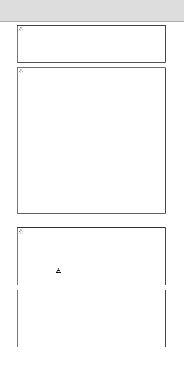
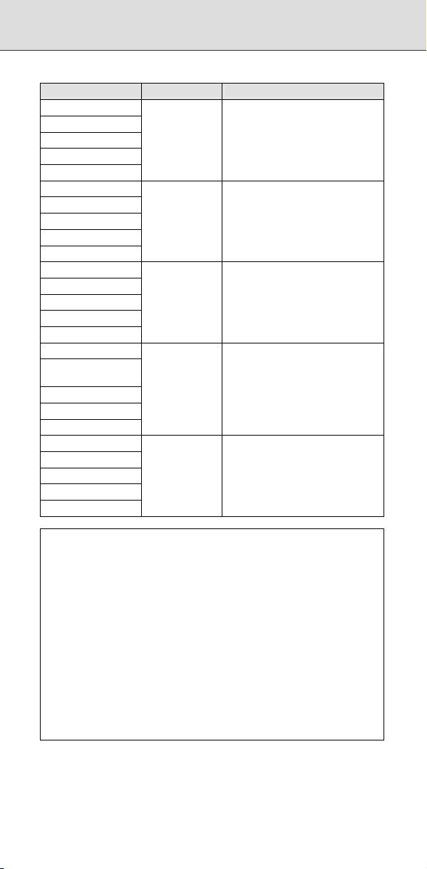
1.1.1 Standard MDI Unit (ONG Key) ......................................2
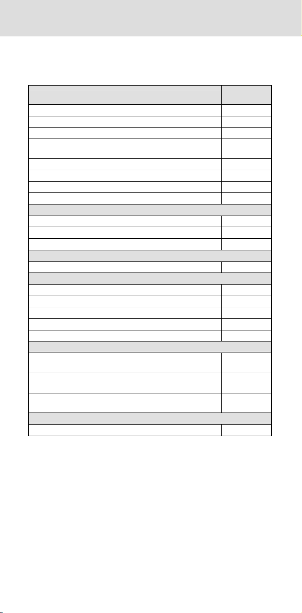
1.1.2 Standard MDI Unit (QWERTY Key)............................... 2
1.1.3 Small MDI Unit (ONG Key)............................................ 3
1.1.4 Explanation of the MDI Keyboard.................................. 4
1.2 FUNCTION KEYS AND SOFT KEYS ..........................................6
1.2.1 General Screen Operations........................................... 6
1.3 SCREENS DISPLAYED BY FUNCTION KEY
1.3.1 Position Display in the Workpiece Coordinate System 13
1.3.2 Position Display in the Relative Coordinate System .... 15
1.3.3 Overall Position Display ..............................................17
1.3.4 Handle Interrupt Display.............................................. 18
1.3.5 Operating Monitor Display........................................... 19
1.4 SCREENS DISPLAYED BY FUNCTION KEY
MODE) ......................................................................................21
1.4.1 Program Contents Display...........................................21
1.4.2 Program Check Screen............................................... 22
1.4.3 Next Block Display Screen .......................................... 23
1.5 SCREENS DISPLAYED BY FUNCTION KEY
MODE) ......................................................................................24
1.5.1 Editing a Program........................................................ 24
1.5.2 Program Folder Screen ............................................... 26
1.6 SCREENS DISPLAYED BY FUNCTION KEY
1.6.1 Setting and Displaying the Tool Offset Value .............. 27
1.6.2 Displaying and Entering Setting Data.......................... 30
1.6.3 Displaying and Setting the Workpiece Origin Offset
Value........................................................................... 32
1.6.4 Direct Input of Workpiece Origin Offset Value
Measured .................................................................... 33
1.6.5 Displaying and Setting Custom Macro Common
Variables ..................................................................... 34
1.6.6 Displaying and Setting the Software Operator's Panel 35
1.6.7 Character-to-Codes Correspondence Table................ 37
1.7 SCREENS DISPLAYED BY FUNCTION KEY
1.7.1 Displaying and Setting Parameters .............................38
1.7.2 Checking by Self-Diagnosis Screen ............................ 39
1.7.3 Coordinate System on Part Drawing and Coordinate
System Specified by CNC - Coordinate System.......... 40
1.7.4 Displaying and Setting Pitch Error Compensation
Data ............................................................................44
1.8 SCREENS DISPLAYED BY FUNCTION KEY
1.8.1 Alarm Display.............................................................. 47
1.8.2 Alarm History Display.................................................. 49
1.9 HELP FUNCTION...................................................................... 50
1.9.1 Initial Menu Screen...................................................... 50
1.9.2 Alarm Detail Screen ....................................................51
1.9.3 Operation Method Screen ...........................................53
1.9.4 Parameter Table Screen .............................................54
.................. 13
(MEM
(EDIT
.................. 27
.................. 38
.................. 47
2 OPERATION LIST ................................................................. 55
3 G CODE ................................................................................. 65
3.1 G CODE LIST IN THE MACHINING CENTER SYSTEM........... 67
c-2
Page 17

3.2 G CODE LIST IN THE LATHE SYSTEM ................................... 72
B-64487EN/03
4 PROGRAM FORMAT ............................................................ 79
5 CUSTOM MACRO ................................................................. 99
5.1 TYPES OF VARIABLES ............................................................ 99
5.2 SYSTEM VARIABLE .................................................................99
5.3 ARGUMENT SPECIFICATION I/II........................................... 118
5.4 ARITHMETIC AND LOGIC OPERATION ................................ 118
5.5 CONTROL COMMAND ........................................................... 119
5.6 MACRO CALL ......................................................................... 120
5.6.1 Simple Call (G65)...................................................... 120
5.6.2 Modal Call: Call After the Move Command (G66)...... 120
5.6.3 Modal Call: Each Block Call (G66.1) .........................121
5.6.4 Macro Call Using a G Code....................................... 121
5.6.5 Macro Call Using a G Code (Specification of Multiple
Definitions) ................................................................ 121
5.6.6 Macro Call Using a G Code with a Decimal Point
(Specification of Multiple Definitions)......................... 121
5.6.7 Macro Call Using an M Code..................................... 122
5.6.8 Macro Call Using an M Code (Specification of Multiple
Definitions) ................................................................ 122
5.6.9 Subprogram Call Using an M Code........................... 122
5.6.10 Subprogram Call Using an M Code (Specification of
Multiple Definitions)................................................... 122
5.6.11 Subprogram Calls Using a T Code............................ 123
5.6.12 Subprogram Calls Using an S Code.......................... 123
5.6.13 Subprogram Calls Using a Secondary Auxiliary
Function .................................................................... 123
5.6.14 Subprogram Call Using a Specific Address............... 124
5.7 INTERRUPTION TYPE CUSTOM MACRO ............................. 125
5.8 EXTERNAL OUTPUT COMMANDS........................................ 126
5.9 COMMAND RANGE................................................................ 127
6 HARDWARE ........................................................................ 129
6.1 LCD-MOUNTED TYPE CONTROL UNIT HARDWARE........... 129
6.1.1 LCD-mounted Type Control Unit (8.4” LCD Unit and
10.4” LCD Unit A)...................................................... 129
6.1.2 LCD-mounted Type Control Unit (10.4” LCD Unit B
6.2 LCD-MOUNTED TYPE CONTROL UNIT (WITH PERSONAL
6.3 STAND-ALONE TYPE CONTROL UNIT HARDWARE............ 152
6.4 HARDWARE COMMON TO LCD-MOUNTED TYPE AND
and 15” LCD Unit) ..................................................... 137
COMPUTER FUNCTION WITH Windows®CE) HARDWARE . 144
6.2.1 Inverter Board and Fan Adapter Board...................... 149
6.2.2 Backup Unit............................................................... 151
6.3.1 Stand-Alone Type Control Unit.................................. 152
6.3.2 Display Unit for Stand-Alone Type Control Unit......... 156
6.3.2.1 Display unit (10.4” LCD unit A) .................. 156
6.3.2.2 Display unit (10.4” LCD unit B and
15” LCD unit)............................................. 159
6.3.2.3 Display unit for automotive manufacturers. 163
6.3.3 Display Unit for Stand-Alone Type Control Unit (with
Personal Computer Function with Windows®CE)...... 168
6.3.3.1 Inverter Board and Fan adapter Board ...... 171
6.3.3.2 Backup unit................................................ 173
STAND-ALONE TYPE CONTROL UNITS............................... 174
6.4.1 Optional Board .......................................................... 174
6.4.1.1 Fast Ethernet board................................... 174
6.4.1.2 Additional axis board ................................. 177
6.4.1.3 HSSB interface board................................ 177
6.4.1.4 PROFIBUS-DP board................................ 178
6.4.1.5 DeviceNet board........................................ 181
6.4.1.6 CC-Link board ........................................... 188
6.4.2 Other Units................................................................ 190
6.4.2.1 Separate detector interface unit................. 190
6.4.2.2 Analog input separate detector interface
unit ............................................................191
c-3
Page 18

Table of Contents
7 PARAMETERS .................................................................... 193
7.1 HOW TO ENTER THE PARAMETERS ................................... 193
7.2 PARAMETER LIST.................................................................. 195
7.2.1 Setting....................................................................... 198
7.2.2 Reader/Puncher Interface ......................................... 198
7.2.3 CNC Screen Display .................................................200
7.2.4 Ethernet / Data Server Function ................................ 200
7.2.5 Power Mate CNC Manager .......................................201
7.2.6 System Configuration................................................ 201
7.2.7 Axis Control / Increment System ...............................202
7.2.8 Coordinate System 1................................................. 204
7.2.9 Stroke Limit Check .................................................... 205
7.2.10 Chuck and Tail Stock Barrier..................................... 207
7.2.11 Feedrate.................................................................... 207
7.2.12 Acceleration/Deceleration Control............................. 210
7.2.13 Servo......................................................................... 212
7.2.14 DI/DO 1..................................................................... 228
7.2.15 Display and Edit 1 .....................................................229
7.2.16 Programs 1................................................................ 238
7.2.17 Pitch Error Compensation .........................................242
7.2.18 Spindle Control.......................................................... 243
7.2.19 Serial Spindle............................................................ 249
7.2.20 Spindle Control 2....................................................... 266
7.2.21 Tool Compensation 1 ................................................ 267
7.2.22 Canned Cycle............................................................ 272
7.2.23 Rigid Tapping............................................................ 275
7.2.24 Scaling/Coordinate Rotation...................................... 278
7.2.25 Single Direction Positioning....................................... 279
7.2.26 Polar Coordinate Interpolation................................... 279
7.2.27 Normal Direction Control ........................................... 279
7.2.28 Index T
7.2.29 Involute Interpolation................................................. 280
7.2.30 Exponential Interpolation........................................... 280
7.2.31 Flexible Synchronous Control 1................................. 280
7.2.32 Straightness Compensation ...................................... 282
7.2.33 Inclination Compensation.......................................... 283
7.2.34 Custom Macros......................................................... 283
7.2.35 Patter Data Input ....................................................... 288
7.2.36 Positioning by Optimum Acceleration........................ 288
7.2.37 Skip Functions........................................................... 289
7.2.38 External Data Input....................................................293
7.2.39 Fine Torque Sensing................................................. 294
7.2.40 Manual Handle Retrace 1.......................................... 294
7.2.41 Graphic Display 1...................................................... 297
7.2.42 Screen Display Colors............................................... 297
7.2.43 Run Hour and Parts Count Display............................ 297
7.2.44 Tool Life Management 1............................................ 298
7.2.45 Position Switch.......................................................... 300
7.2.46 Manual/Automatic Operation Functions..................... 301
7.2.47 Manual Handle.......................................................... 302
7.2.48 Manual Linear/Circular Interpolation.......................... 303
7.2.49 Reference Position with Mechanical Stopper ............303
7.2.50 Software Operator's Panel ........................................303
7.2.51 Program Restart 1..................................................... 304
7.2.52 Software Operator's Panel 2...................................... 305
7.2.53 High-speed Cutting....................................................305
7.2.54 Fixture Offset............................................................. 306
7.2.55 Polygon Turning ........................................................ 307
7.2.56 Electric Gear Box
7.2.57 Axis Control by PMC 1 .............................................. 310
7.2.58 Multi-path ..................................................................312
7.2.59 Interference Check for Each Path..............................312
7.2.60 Synchronous/Composite Control and Superimposed
7.2.61 Angular Axis Control.................................................. 316
7.2.62 Axis Synchronous Control ......................................... 317
able ...............................................................280
(EGB)............................................ 308
Control 1 ...................................................................313
c-4
Page 19

7.2.63 Sequence Number Comparison and Stop ................. 319
7.2.64 Chopping/ High precision oscillation function ............319
7.2.65 AI Contour Control..................................................... 319
7.2.66 High-speed Position Switch....................................... 320
7.2.67 Others ....................................................................... 322
7.2.68 Maintenance.............................................................. 323
7.2.69 Macro Executor ......................................................... 323
7.2.70 Wrong Operation Prevention Function ...................... 326
7.2.71 Automatic Data Backup............................................. 327
7.2.72 Axis Control............................................................... 328
7.2.73 Parallel Axis Control.................................................. 328
7.2.74 Axis Switching........................................................... 328
7.2.75 Tool Retract and Recover..........................................328
7.2.76 Screen Display Colors 2............................................ 328
7.2.77 High-speed Smooth TCP 1........................................ 329
7.2.78 Dual Check Safety..................................................... 329
7.2.79 Diagnosis ..................................................................329
7.2.80 Three-dimensional Rotary Error Compensation.........329
7.2.81 Three-dimensional Error Compensation.................... 330
7.2.82 3-dimensional Machine Position Compensation........ 331
7.2.83 Rotation Area Interference Check ............................. 332
7.2.84 Built-in 3D Interference Check................................... 332
7.2.85 Spindle Control Based on Servo Motor/Cs Contour
Control 1 ...................................................................347
7.2.86 Path Table Operation ................................................ 349
7.2.87 Workpiece Setting Error Compensation 1..................349
7.2.88 Linear Inclination Compensation ...............................350
7.2.89 Tilted Working Plane Indexing................................... 350
7.2.90 Axis Control / Increment System 2 ............................ 350
7.2.91 DI/DO 2..................................................................... 351
7.2.92 Feedrate Control and Acceleration/Deceleration
Control ......................................................................351
7.2.93 Program R
7.2.94 Tool Center Point Control.......................................... 351
7.2.95 Coordinate System 2................................................. 352
7.2.96 Synchronous/Composite Control and Superimposed
Control 2 ...................................................................352
7.2.97 Programs 2................................................................ 353
7.2.98 Display and Edit 2 .....................................................353
7.2.99 Embedded Macro 1................................................... 355
7.2.100 Display and Edit 3 ..................................................... 355
7.2.101 Graphic Display 2...................................................... 355
7.2.102 Display and Edit 4 ..................................................... 356
7.2.103 Tool Compensation 2................................................ 358
7.2.104 Optimum Torque Acceleration/Deceleration For Rigid
Tapping ..................................................................... 359
7.2.105 Arbitrary Speed Threading ........................................ 360
7.2.106 Programs 3................................................................ 360
7.2.107 Machining Quality Level Adjustment.......................... 363
7.2.108 Workpiece Setting Error Compensation 2.................. 363
7.2.109 High-speed Smooth TCP 2........................................ 363
7.2.110 Servo 2...................................................................... 363
7.2.111 Axis Control by PMC 2 .............................................. 364
7.2.112 PMC .......................................................................... 364
7.2.113 Dual Check Safety 2..................................................365
7.2.114 Embedded Macro Functions 2................................... 365
7.2.115 High-speed Position Switch 2.................................... 366
7.2.116 Malfunction Protection............................................... 366
7.2.117 Manual Handle 2....................................................... 366
7.2.118 Synchronous/Composite Control and Superimposed
Control 3 ...................................................................369
7.2.119 Axis Control by PMC 3 .............................................. 369
7.2.120 External Deceleration Positions Expansion ...............370
7.2.121 Display and Edit 5 ..................................................... 370
7.2.122 Tool Management Functions..................................... 373
7.2.123 Tool Life M
estart 2..................................................... 351
anagement 2............................................ 375
B-64487EN/03
c-5
Page 20

Table of Contents
7.2.124 Straightness Compensation 2 ................................... 376
7.2.125 Flexible Synchronous Control 2................................. 377
7.2.126 Programs 4................................................................ 378
7.2.127 Tool Management ..................................................... 378
7.2.128 Manual Liner/Circular Interpolation............................ 378
7.2.129 Canned Cycles for Drilling M Code Output
Improvement ............................................................. 379
7.2.130 Tool Management ..................................................... 379
7.2.131 Machining Condition Selection Functions .................. 379
7.2.132 Dual Check Safety 3..................................................380
7.2.133 FSSB 1...................................................................... 381
7.2.134 Linear Scale with Absolute Address Reference
Position ..................................................................... 381
7.2.135 Pivot Axis Control ...................................................... 381
7.2.136 FSSB 2...................................................................... 381
7.2.137 SERVO GUIDE Mate ................................................ 382
7.2.138 Graphic Display 3...................................................... 382
7.2.139 Embedded Ethernet .................................................. 382
7.2.140 Rotation Area Interference Check 2 ..........................383
7.2.141 Periodical Secondary Pitch Compensation................ 385
7.2.142 Manual Handle Retrace 2.......................................... 386
7.2.143 AI Contour Control 2..................................................386
7.2.144 Cylindrical Interpolation .............................................387
7.2.145 Optimum Torque Acceleration/Deceleration.............. 387
7.2.146 Nano Smoothing .......................................................388
7.2.147 Tool Compensation 3................................................ 388
7.2.148 5-axis Machining Function......................................... 391
7.2.149 FSSB 3...................................................................... 393
7.2.150 Display and Edit 6 ..................................................... 395
7.2.151 High precision oscillation function.............................. 395
7.2.152 Spindle Control Based on Servo Motor/Cs Contour
Control 2 ...................................................................396
7.2.153 Spindle Unit Compensation and Nutating Rotary
H
7.2.154 Graphic Display 4...................................................... 398
ead Tool Length Compensation.............................. 397
8 ALARM LIST........................................................................ 401
8.1 ALARM LIST (CNC)................................................................. 401
8.1.1 Alarms on Program and Operation (PS Alarm),
Background Edit Alarms (BG Alarm), Communication
Alarms (SR Alarm) ....................................................401
8.1.2 Parameter Writing Alarm (SW Alarm)........................ 452
8.1.3 Servo Alarms (SV Alarm) ..........................................452
8.1.4 Overtravel Alarms (OT Alarm)................................... 463
8.1.5 Memory File Alarms (IO Alarm) ................................. 464
8.1.6 Alarms Requiring Power to be Turned Off
(PW Alarm)................................................................ 464
8.1.7 Spindle Alarms (SP Alarm)........................................ 467
8.1.8 Overheat Alarms (OH Alarm) ....................................470
8.1.9 Other Alarms (DS Alarm)........................................... 470
8.1.10 Malfunction Prevention Function Alarms (IE Alarm) ..475
8.2 ALARM LIST (SERIAL SPINDLE) ...........................................477
8.3 SYSTEM ALARMS .................................................................. 495
8.3.1 Overview ................................................................... 495
8.3.2 Operations on the System Alarm Screen................... 496
8.3.3 System Alarms Detected by Hardware...................... 499
8.3.4 System Alarms 114 to 160 (Alarms on the FSSB)..... 500
8.4 SYSTEM ALARMS RELATED TO THE PMC AND I/O LINK... 504
8.5 PMC ALARM MESSAGES ......................................................509
8.6 POWER MATE CNC MANAGER FUNCTION .........................519
8.7 ERROR DISPLAY ON THE SPINDLE AMPLIFIER ................. 520
9 SIGNAL LIST (X/Y, G/F) ...................................................... 523
9.1 LIST OF SIGNALS .................................................................. 525
9.1.1 List of Signals (in Order of Symbols) ......................... 525
9.1.2 List of Signals (in Order of Addresses) ...................... 546
9.2 LIST OF ADDRESSES ............................................................ 567
c-6
Page 21

B-64487EN/03
10 PMC...................................................................................... 597
10.1 OPERATING THE PMC SCREEN........................................... 597
10.1.1 Transition of the PMC Screens.................................. 598
10.2 PMC DIAGNOSIS/MAINTENANCE SCREEN
([PMC MAINTE])...................................................................... 599
10.2.1 Monitoring PMC Signal Status ([STATUS] Screen) ... 599
10.2.2 Checking PMC Alarms ([PMC ALARM] Screen)........ 600
10.2.3 Setting and Displaying Variable Timers ([TIMER]
Screen) .....................................................................600
10.2.4 Setting and Displaying Counter Values ([COUNTR]
Screen) .....................................................................602
10.2.5 Setting and Displaying Keep Relays ([KEEP RELAY]
Screen) .....................................................................603
10.2.6 Setting and Displaying Data Tables ([DATA] Screen) 608
10.2.7 Data Input/Output ([I/O] Screen)................................ 611
10.2.8 Displaying the I/O Device Connection Status
([I/O DEVICE] Screen) ..............................................613
10.2.9 Signal Trace Function ([TRACE] Screen).................. 615
10.2.10 Setting of Trace Parameter ([TRACE SETING]
Screen) .....................................................................615
10.2.11 Execution of Trace .................................................... 617
10.2.12 Monitoring the Network Communication Status and
10.3 LADDER DIAGRAM MONITOR AND EDITOR SCREENS
10.4 PMC CONFIGURATION DATA SETTING SCREENS ([PMC
the PMC Signal Status ([I/O DGN] Screen) ...............619
([PMC LADDER])..................................................................... 620
10.3.1 Displaying a Program List ([LIST] Screen)................. 621
10.3.2 Monitoring Ladder Diagrams ([LADDER] Screen) .....622
10.3.3 Collective Monitor Function ....................................... 623
10.3.4 Editing Ladder Programs........................................... 625
10.3.5 NET EDITOR Screen ................................................ 626
10.3.6 PROGRAM LIST EDITOR Screen............................. 627
10.3.7 Duplicate Coil Check Function ..................................628
CONFIG]) ................................................................................ 629
10.4.1 Displaying and Editing Title Data ([TITLE] Screens).. 630
10.4.1.1 PMC title data display screen.................... 630
10.4.1.2 Title (message) data display screen ..........630
10.4.2 Displaying and Editing Symbol and Comment Data
([SYMBOL] Screens)................................................. 631
10.4.2.1 SYMBOL & COMMENT DATA VIEWER
10.4.2.2 SYMBOL & COMMENT DATA VIEWER
10.4.3 Displaying and Editing Message Data ([MESAGE]
Screens).................................................................... 632
10.4.4 Displaying and Editing I/O Module Allocation Data
([MODULE] Screens) ................................................632
10.4.4.1 I/O MODULE VIEWER screen...................632
10.4.5 Displaying and Editing PMC Settings ([SETING]
Screens).................................................................... 633
10.4.6 Displaying the Status of PMCs and Changing
the Target PMC ([PMC STATUS] Screens)............... 636
10.4.7 Displaying and Setting Parameters for the Online
Function ([ONLINE] Screen)...................................... 636
10.4.8 Displaying and Setting System Parameters
([SYSTEM PARAM] Screens) ...................................637
10.4.9 Displaying and Setting Configuration Parameters
([CONFIG PARAM] Screens) .................................... 639
10.4.9.1 MENU screen............................................ 639
10.4.9.2 CNC-PMC INTERFACE screen................. 639
10.4.9.3 MACHINE SIGNAL INTERFACE screen ... 640
10.4.9.4 LADDER EXECUTION screen...................641
10.4.9.5 PMC MEMORY SETTING screen ............. 642
10.4.10 Displaying and Editing I/O Link i Assignment Data
([I/O LINK I] Screen).................................................. 642
screen (basic f
screen (extended format)........................... 631
ormat)................................. 631
c-7
Page 22

Table of Contents
10.4.10.1 Displaying group information of I/O Link i
10.4.10.2 Displaying slot information of I/O Link i
10.4.10.3 Displaying title information of I/O Link i
10.4.10.4 Setting enabled groups of I/O Link i
10.5 FUNCTIONAL INSTRUCTIONS.............................................. 646
10.5.1 List of Functional Instructions.................................... 646
10.5.2 Details of Functional Instructions............................... 650
10.5.2.1 Timer......................................................... 650
10.5.2.2 Counter ..................................................... 650
10.5.2.3 Data transfer.............................................. 651
10.5.2.4 Table data .................................................653
10.5.2.5 Comparison............................................... 655
10.5.2.6 Bit operation .............................................. 657
10.5.2.7 Code conversion........................................663
10.5.2.8 Operation instruction .................................665
10.5.2.9 CNC functions ...........................................668
10.5.2.10 Program control......................................... 669
10.5.2.11 Rotation control ......................................... 671
10.5.3 Functional Instructions (Arranged in Sequence of
SUB No.)................................................................... 671
10.6 I/O MODULE ASSIGNMENT NAMES (I/O Link) ...................... 676
assignment data ........................................ 643
assignment data ........................................ 644
assignment data ........................................ 644
assignment data (assignment selection
function)..................................................... 645
11 ETHERNET .......................................................................... 679
11.1 OVERVIEW ............................................................................. 679
11.2 ETHERNET MOUNTING LOCATIONS ................................... 679
11.3 LIST OF ETHERNET-RELATED SCREENS ...........................679
11.3.1 Setting and Maintenance (SYSTEM key) .................. 679
11.3.2 File Operation (PROG Key)....................................... 680
11.3.3 Error Message (MESSAGE Key)............................... 680
11.4 EMBEDDED ETHERNET ........................................................681
11.4.1 Parameter Setting Screen ......................................... 681
11.4.2 FTP File Transfer Operation Screen.......................... 685
11.4.3 Maintenance Screen for Embedded Ethernet
Function .................................................................... 686
11.4.4 Log Screen of the Embedded Ethernet Function....... 690
11.5 ETHERNET OPTIONAL BOARD............................................. 695
11.5.1 Parameter Setting Screen ......................................... 695
11.5.2 Fast Data Server Operation Screen .......................... 702
11.5.3 Machine Remote Diagnosis Operation Screens........ 705
11.5.4 Maintenance Screen (for Data Server Function)........708
11.5.5 Maintenance Screen ................................................. 709
11.5.6 Error Message Screen ..............................................712
11.6 TROUBLESHOOTING............................................................. 718
11.6.1 Confirmation of Connection with the Hub Unit........... 718
11.6.2 Confirmation of Each Parameter Setting ................... 718
11.6.3 Confirmation of Communications Based on the Ping
Command.................................................................. 718
12 POWER MATE CNC MANAGER FUNCTION ..................... 721
12.1 SCREEN DISPLAY.................................................................. 721
12.2 PARAMETERS........................................................................ 725
12.3 WARNING............................................................................... 726
13 DIAGNOSIS INFORMATION ............................................... 727
13.1 DIAGNOSIS FUNCTION ......................................................... 727
13.1.1 Displaying Diagnosis Screen..................................... 727
13.2 LIST OF DIAGNOSIS INFORMATION (DGN) ......................... 727
13.2.1 Display of Causes of Instructions not Functioning ..... 727
13.2.2 State of TH Alarm...................................................... 727
13.2.3 Details of Serial Pulsecoder ......................................728
13.2.4 Details of Separate Serial Pulsecoder Alarms........... 729
c-8
Page 23

13.2.5 Details of Invalid Servo Parameter Alarms (on
the CNC Side) ........................................................... 729
13.2.6 Position Error Amount ............................................... 730
13.2.7 Machine Position....................................................... 730
13.2.8 Distance from the end of the deceleration dog to
the first grid point....................................................... 730
13.2.9 Reference Counter.................................................... 730
13.2.10 Machine Coordinates on the Angular/Cartesian Axes730
13.2.11 Servo Motor Temperature Information....................... 730
13.2.12 Cause that Sets Parameter APZ (No. 1815#4) to 0... 731
13.2.13 Details of Invalid Servo Parameter Setting Alarms
(on the Servo Side) ...................................................731
13.2.14 Detailed Descriptions about Invalid Servo Parameter
Setting Alarms........................................................... 732
13.2.15 Diagnosis Data Related to the Inductosyn Absolute
Position Detector....................................................... 740
13.2.16 Diagnosis Data Related to the Serial Spindles .......... 740
13.2.17 Diagnosis Data Related to Rigid Tapping.................. 741
13.2.18 Diagnosis Data Related to the Small-hole Peck
Drilling Cycle ............................................................. 742
13.2.19 Diagnosis Data Related to the Dual Position
Feedback Function.................................................... 743
13.2.20 Automatic Alteration of Tool Position Compensation. 743
13.2.21 Data for Adjusting the Compensation of the Start
Position of Thread Cutting when the Spindle Speed
Is Changed................................................................ 744
13.2.22 State of High-speed HRV Current Control................. 744
13.2.23 Thermal Growth Compensation along Tool Vector.... 744
13.2.24 Spindle Error and Warning States .............................744
13.2.25 Digital Servo (2) ........................................................ 745
13.2.26 Automatic Data Backup ............................................. 745
13.2.27 Fan Rotation Speed .................................................. 746
13.2.28 Custom Macro / Execution Macro / Auxiliary Macro ..746
13.2.29 Spindle Revolution Number History Function ............746
13.2.30 Servo Leakage Detection Function............................ 746
13.2.31 Spindle Leakage Detection Function ......................... 747
13.2.32 Internal cooling fan for the servo amplifier................. 748
13.2.33 Radiator cooling fan for servo amplifier ..................... 748
13.2.34 Internal cooling fan for common power supply........... 748
13.2.35 Radiator cooling fan for common power supply......... 749
13.2.36 Internal cooling fan
13.2.37 Radiator cooling fan for spindle amplifier................... 750
13.2.38 Internal cooling fan for common power supply........... 750
13.2.39 Radiator cooling fan for common power supply......... 750
13.2.40 Tool offset conversion (G44.1) ..................................751
13.2.41 Built-in 3D Interference Check................................... 753
13.2.42 Detector battery exhaustion....................................... 753
13.2.43 Diagnosis Data Related to Axis Synchronous
Control ......................................................................753
13.2.44 Diagnosis Data Related to Synchronous/Composite
Control ......................................................................753
13.2.45 Diagnosis Data Related to Axis Synchronous
Control 2 ...................................................................754
13.2.46 Detailed Descriptions about Invalid FSSB Setting
Alarms....................................................................... 754
13.2.47 Absolute Position Detection....................................... 758
13.2.48 Diagnosis Data Related to Linear Scale with
Absolute Address Reference Marks.......................... 758
13.2.49 Wrong Operation Prevention Function ...................... 759
13.2.50 Flexible Path Axis Assignment Information................ 759
13.2.51 Total Current Actual Power Consumption of All
Servo/Spindle............................................................ 760
13.2.52 Chopping................................................................... 761
13.2.53 Communication ......................................................... 761
13.2.54 Total Current Actual Power Consumption of All
Servo/Spindle............................................................ 762
for spindle amplifier ....................749
B-64487EN/03
c-9
Page 24

Table of Contents
13.2.55 Current Actual Power Consumption of Each Servo ... 762
13.2.56 Current Actual Power Consumption of Each Spindle. 762
13.2.57 Cumulative Values of Total Power Consumption of
All Servo/Spindle....................................................... 762
13.2.58 Cumulative Power Consumption of Each Servo........ 763
13.2.59 Cumulative Power Consumption of Each Spindle...... 763
13.2.60 Interpolation State..................................................... 763
13.2.61 3-dimensional Machine Position Compensation ........ 763
13.2.62 Automatic Phase Synchronization for Flexible
Synchronous Control................................................. 764
14 HISTORY FUNCTION .......................................................... 765
14.1 OVERVIEW OF HISTORY FUNCTION ................................... 765
14.2 ALARM HISTORY ................................................................... 765
14.2.1 Screen Display .......................................................... 765
14.2.2 Erasing History Data from the ALARM HISTORY
Screen....................................................................... 766
14.2.3 External/Macro Alarm Display................................... 766
14.3 EXTERNAL OPERATOR MESSAGE HISTORY ..................... 767
14.3.1 Screen Display .......................................................... 767
14.3.2 Erasing History Data from the External Operator
Message History Screen ........................................... 767
14.3.3 Parameter Setting ..................................................... 768
14.4 OPERATION HISTORY........................................................... 768
14.4.1 Parameter Setting ..................................................... 768
14.4.2 Screen Display .......................................................... 770
14.4.3 Inputting and Outputting Operation History Data ....... 772
14.4.3.1 Outputting operation history data............... 772
14.4.4 History Data Not Displayed on the Screen ................ 772
14.4.5 Erasing History Data from the Operation History
14.5 SELECTING OPERATION HISTORY SIGNALS .....................773
14.6 OUTPUTTING ALL HISTORY DATA....................................... 775
Screen....................................................................... 773
15 WAVEFORM DIAGNOSIS ................................................... 777
15.1 WAVEFORM DIAGNOSIS PARAMETER SCREEN................ 777
15.1.1 Tracing Data..............................................................778
15.1.2 Outputting Data......................................................... 779
16 DIGITAL SERVO.................................................................. 783
16.1 INITIAL SETTING SERVO PARAMETERS............................. 783
16.2 FSSB SETTING SCREEN ....................................................... 793
16.2.1 FSSB Display and Setting Screen............................. 793
16.3 SERVO TUNING SCREEN...................................................... 801
16.3.1 Parameter Setting ..................................................... 801
16.3.2 Displaying Servo Tuning Screen ...............................801
16.4 αi SERVO INFORMATION SCREEN ...................................... 801
16.5 αi SERVO WARNING INTERFACE ........................................ 805
16.6 ADJUSTING REFERENCE POSITION (DOG METHOD)........ 806
16.7 REFERENCE POSITION SETTING WITHOUT DOGS ........... 808
17 AC SPINDLE........................................................................ 811
17.1 SERIAL INTERFACE AC SPINDLE......................................... 811
17.1.1 Overview of Spindle Control...................................... 811
17.1.1.1 Method A of gear change for M series
17.1.1.2 Method B of gear change for M series
17.1.1.3 T series .....................................................812
17.1.2 Automatic Setting of Standard Parameters................812
17.1.3 Spindle Setting and Tuning Screen ........................... 814
17.1.3.1 Display method.......................................... 814
17.1.3.2 Spindle setting screen ............................... 814
17.1.3.3 Spindle tuning screen................................ 815
17.1.3.4 Spindle monitor screen.............................. 817
17.1.3.5 Correspondence between operation mode
17.1.4 Warning Interface...................................................... 821
(parameter SGB (No. 3705#2)=0) .............811
(bit 2 (SGB) of parameter No. 3705 is 1) ... 812
and parameters on spindle tuning screen.. 819
c-10
Page 25

17.1.5 Spindle Information Screen ....................................... 823
B-64487EN/03
18 MAINTENANCE INFORMATION......................................... 827
18.1 SCREEN DISPLAY AT POWER ON ....................................... 827
18.1.1 Display until the CNC Starts...................................... 827
18.1.2 IPL Display................................................................ 827
18.1.3 System Label Check Error......................................... 828
18.2 SYSTEM CONFIGURATION SCREEN DISPLAY ...................828
18.2.1 Hardware Configuration Screen ................................829
18.2.2 Software Configuration Screen.................................. 830
18.3 CNC STATE DISPLAY ............................................................833
18.4 PERIODICAL MAINTENANCE SCREEN ................................835
18.4.1 Overview ................................................................... 835
18.4.1.1 Screen configuration.................................. 835
18.4.1.2 Procedure.................................................. 836
18.4.2 Screen Display and Setting ....................................... 836
18.4.2.1 Status screen display and setting.............. 836
18.4.2.2 Setting screen display and setting .............841
18.4.3 Registered Data Input/Output.................................... 844
18.4.3.1 Data output................................................ 844
18.4.3.2 Data input.................................................. 845
18.4.4 Parameter ................................................................. 845
18.4.5 Warning..................................................................... 845
18.5 MAINTENANCE INFORMATION SCREEN............................. 846
18.5.1 Overview ................................................................... 846
18.5.2 Screen Display and Operation................................... 846
18.5.2.1 Screen display........................................... 846
18.5.2.2 Edit operation ............................................ 847
18.5.2.3 Operation of soft keys................................ 848
18.5.2.4 Input/output of maintenance information.... 849
18.5.2.5 Half-size kana input................................... 850
18.5.3 Parameter ................................................................. 851
18.5.4 Warning..................................................................... 852
19 MAINTENANCE FUNCTION ............................................... 853
19.1 INPUT AND OUTPUT OF DATA .............................................853
19.1.1 Setting Parameters for Input/Output.......................... 853
19.1.2 Inputting/Outputting Data........................................... 854
19.1.2.1 Confirming the parameters required for
19.1.2.2 Outputting CNC parameters ...................... 857
19.1.2.3 Outputting pitch error compensation
19.1.2.4 Outputting custom macro variable values.. 857
19.1.2.5 Outputting tool compensation amount ....... 857
19.1.2.6 Outputting part program.............................857
19.1.2.7 Inputting CNC parameters......................... 858
19.1.2.8 Inputting pitch error compensation
19.1.2.9 Inputting custom macro variable values..... 860
19.1.2.10 Inputting tool compensation amount.......... 860
19.1.2.11 Inputting part programs..............................860
19.1.3 Input/Output on the ALL IO Screen ...........................861
19.1.3.1 Inputting/outputting a program................... 861
19.1.3.2 Inputting/outputting parameters................. 862
19.1.3.3 Inputting/outputting offset data................... 862
19.1.3.4 Inputting/outputting custom macro
19.2 MEMRY CARD SLOT.............................................................. 864
19.2.1 Overview ................................................................... 864
19.2.2 Hardware Configuration ............................................ 864
19.3 BOOT SYSTEM....................................................................... 865
19.3.1 Overview ................................................................... 865
19.3.1.1 Displaying the power ON sequence...........865
19.3.1.2 Starting the boot system............................ 866
19.3.1.3 System files and user files......................... 866
19.3.2 Screen Configuration and Operating Procedure........ 867
data output ................................................855
amount ......................................................857
amount ......................................................859
common variables .....................................863
c-11
Page 26

Table of Contents
19.3.2.1 USER DATA LOADING/SYSTEM DATA
19.3.2.2 SYSTEM DATA CHECK screen................ 870
19.3.2.3 SYSTEM DATA DELETE screen............... 872
19.3.2.4 SYSTEM DATA SAVE screen................... 874
19.3.2.5 SRAM DATA UTILITY screen.................... 875
19.3.2.6 MEMORY CARD FORMAT screen............ 876
19.3.2.7 Quitting BOOT........................................... 877
19.3.3 Error Messages and Required Actions...................... 877
19.4 LED DISPLAY ......................................................................... 879
19.4.1 Overview ................................................................... 879
19.4.2 7-segment LED Indications (Turned on).................... 879
19.4.3 7-segment LED Indications (Blinking)........................ 880
19.5 MAINTENANCE OF PERSONAL COMPUTER FUNCTION
(BOOT AND IPL)..................................................................... 882
19.5.1 Overview ................................................................... 882
19.5.2 Changing Start Sequences........................................ 883
19.5.3 Explanation of Screens .............................................883
19.5.3.1 BOOT screen ............................................884
19.5.3.2 IPL screen ................................................. 886
19.5.4 Other Screens........................................................... 887
19.5.4.1 CNC alarm screen..................................... 887
19.5.4.2 Status screen (Personal computer function
19.5.4.3 Option setting screen................................. 888
19.6 COLOR SETTING SCREEN.................................................... 890
19.6.1 Screen Display .......................................................... 890
19.6.2 Operations for Color Setting...................................... 890
19.7 MAINTENANCE ON THE USB FUNCTION............................. 891
LOADING screen....................................... 868
with Windows XP only) .............................. 887
c-12
Page 27

Page 28

1 SCREEN DISPLAY AND OPERATION
1.1 SETTING AND DISPLAY UNITS
The MDI units are shown in below.
Standard MDI Unit (ONG Key).........................................................1.1.1
Standard MDI Unit (QWERTY Key)..................................................1.1.2
Small MDI Unit (ONG Key)...............................................................1.1.3
1
Page 29
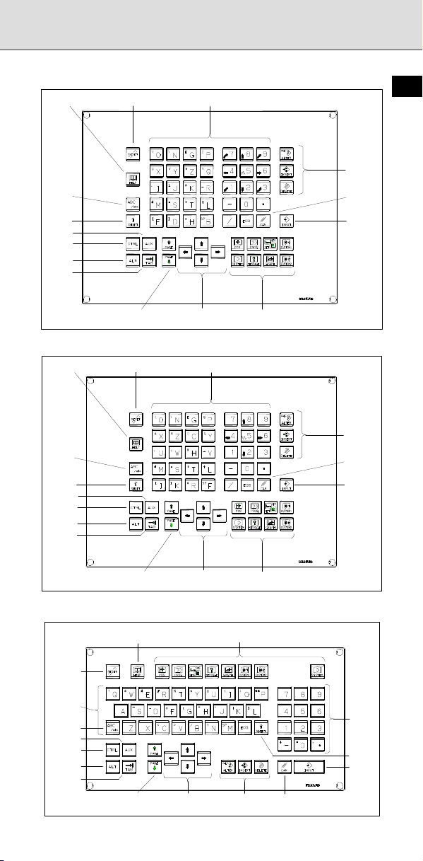
A
A
A
A
A
A
A
A
A
1.1.1 Standard MDI Unit (ONG Key)
- Unit with machining center system
Reset key Help key
ddress/numeric keys
B-64487EN/03
1
Uppercase/
lowercase
switch key
Shift key
UX key
CTRL key
LT key
TAB key
Page change keys
(Page keys)
- Unit with lathe system
Uppercase/
lowercase
switch key
Shift key
CTRL key
TAB key
UX key
LT key
Reset key Help key
Page change keys
(Page keys)
Cursor move keys
(Cursor keys)
ddress/numeric keys
Cursor move keys
(Cursor keys)
Function keys
Function keys
1.1.2 Standard MDI Unit (QWERTY Key)
Help key
Function keys
Edit keys
Cancel
(CAN) key
Input key
Edit keys
Cancel
(CAN) key
Input key
Reset key
ddress keys
Uppercase/
lowercase
switch key
UX key
CTRL key
LT key
TAB key
Page change keys
(Page keys)
Cursor move keys
(Cursor keys)
Edit keys
Cancel (CAN) key
Numeric
keys
Shift
key
Input
key
2
Page 30
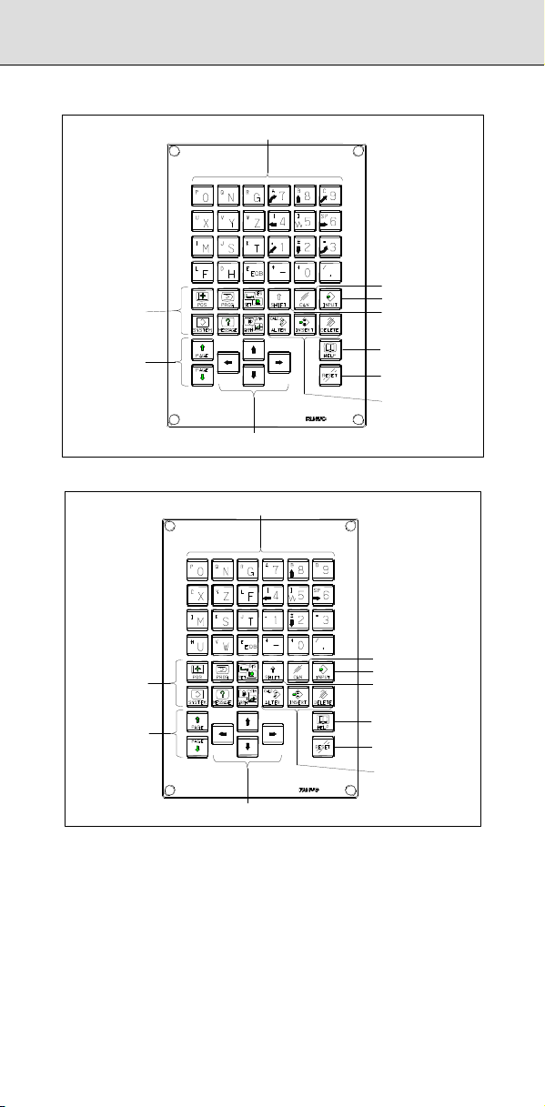
1 SCREEN DISPLAY AND OPERATION
1.1.3 Small MDI Unit (ONG Key)
- Unit with machining center system
Function keys
Address/numeric keys
Cancel (CAN) key
Input key
Shift key
Page change keys
(Page keys)
- Unit with lathe system
Function keys
Page change keys
(Page keys)
Cursor move keys
(Cursor keys)
Address/numeric keys
Cursor move keys
(Cursor keys)
Help key
Reset key
Edit keys
Cancel (CAN) key
Input key
Shift key
Help key
Reset key
Edit keys
3
Page 31

1.1.4 Explanation of the MDI Keyboard
No. Name Explanation
1
2
3 Soft keys
4
5
6
7
8
9
Table 1.1 (a) Explanation of the MDI keyboard
Reset key
Help key
Press this key to reset the CNC, to cancel an
alarm, etc.
Press this button to use the help function when
uncertain about the operation of an MDI key (help
function).
The soft keys have various functions, according
to the Applications. The soft key functions are
displayed on the display unit.
Address and
numeric keys
Press these keys to input alphabetic, numeric,
and other characters.
Shift key
Some keys have two characters on their keytop.
Pressing the
Special character ^ is displayed on the screen
when a character indicated at the top left corner
on the keytop can be entered.
When an address or a numerical key is pressed,
the data is input to the buffer, and it is displayed
Input key
on the screen. To copy the data in the key input
buffer to the offset register, etc., press the
key. This key is equivalent to the [INPUT] key of
the soft keys, and either can be pressed to
produce the same result.
Press this key to delete the last character or
symbol input to the key input buffer.
Example) When the key input buffer displays
Cancel (CAN) key
> N001X100Z_
and the cancel key
Z is canceled and
>N001X100_
is displayed.
Press these keys when editing the program.
Edit keys
Function keys
. . .
: ALTER
: INSERT
: DELETE
Press theses keys to switch display screens for
each function.
See Sections 1.3 to 1.8 for details of the function
keys.
key switches the characters.
B-64487EN/03
is pressed,
1
4
Page 32

1 SCREEN DISPLAY AND OPERATION
No. Name Explanation
There are four different cursor move keys.
: This key is used to move the cursor to
the right or in the forward direction. The
cursor is moved in short units in the
forward direction.
Cursor move keys
(Cursor keys)
10
: This key is used to move the cursor to
the left or in the reverse direction. The
cursor is moved in short units in the
reverse direction.
: This key is used to move the cursor in a
downward or forward direction. The
cursor is moved in large units in the
forward direction.
: This key is used to move the cursor in an
upward or reverse direction. The cursor
is moved in large units in the reverse
direction.
Page change keys
(Page keys)
11
Two kinds of page change keys are described
below.
: This key is used to changeover the page
on the screen in the forward direction.
: This key is used to changeover the page
on the screen in the reverse direction.
Uppercase/
lowercase switch
12
key
Press this key to switch between uppercase and
lowercase when entering alphabetic characters.
PC function key
13
Explanation
These keys are used with the personal computer
function.
- 15” LCD/MDI soft key configuration
The 15” LCD panel has 12 soft keys horizontally and 9 soft keys
vertically.
As shown below, the 8 vertical soft keys and the lowermost key are used
as chapter selection soft keys. By pressing each of these keys, the
screen (chapter) belonging to each function can be selected. The
horizontal 12 soft keys are used to perform operations on the screen
selected with a vertical soft key.
For an LCD display with a touch panel, touch a soft key on the screen to
select it.
5
Page 33

Horizontal soft keys
B-64487EN/03
Vertical soft keys
Displays operations on selected chapter.
1
In this manual, the descriptions below assume a 10.4" LCD display panel
with 12 soft keys.
- Key operation with multi-path control
In the multi-path control, be sure to select the tool post for which data is
specified, using the path selection switch on the machine operator's
panel. Then, perform keyboard operation, such as displaying or
specifying various data items, and editing a program.
1.2 FUNCTION KEYS AND SOFT KEYS
The function keys are used to select the type of screen (function) to be
displayed. When a soft key (section select soft key) is pressed
immediately after a function key, the screen (section) corresponding to
the selected function can be selected.
1.2.1 General Screen Operations
- Procedure
1 By pressing a function key on the MDI unit, the chapter selection
soft keys that belong to the function are displayed.
Example 1)
Operation selection key
Chapter selection soft keys Continuous menu key
2 When one of the chapter selection soft keys is pressed, the screen
of the chapter is displayed. If the soft key of a desired chapter is not
displayed, press the continuous menu key.
In a chapter, a further choice may be made from multiple chapters.
3 When the screen of a desired chapter is displayed, press the
operation selection key to display operations to be performed.
4 Select a desired operation with the operation selection soft key.
Depending on the operation to be executed, an auxiliary menu of
soft keys is displayed. Perform an operation according to the
indications on the auxiliary menu.
Example 2)
Return menu key Operation selection soft keys
6
Page 34

1 SCREEN DISPLAY AND OPERATION
Example 3)
Auxiliary menu
5 To return to the display of chapter selection soft keys, press the
return menu key.
A general screen display procedure is provided above.
The actual display procedure varies from one screen to another.
For details, see each description of operation.
Position display screen
The chapter selection soft keys that belong to the function key and
the function of each screen are described below.
Page 1
Page 2
(1) (2) (3) (4) (5)
ABS REL ALL HNDL (OPRT)
(6) (7) (8) (9) (10)
MONI 5AXMAN
(OPRT)
+
+
Table 1.2.1 (a) Position display screen
Chapter
No.
menu
Description
(1) ABS Selects the absolute coordinate display screen.
(2) REL Selects the relative coordinate display screen.
(3) ALL Selects the overall coordinate display screen.
(4) HNDL Selects the operation screen for manual handle operation.
(6) MONI Selects the screen for displaying the servo axis load meter,
serial spindle load meter, and speedometer.
(7) 5AXMAN Displays a handle pulse interrupt amount in 3-dimensional
manual feed.
Program screen
The chapter selection soft keys that belong to the function key and
the function of each screen are described below.
Page 1
Page 2
(1) (2) (3) (4) (5)
FOLDER
PROGRA
M
(6) (7) (8) (9) (10)
RSTR
JOG
NEXT
CHECK (OPRT)
ROBOT
SELECT
(OPRT)
+
+
Table 1.2.1 (b) Program
Chapter
No.
menu
Description
(1) PROGRAM Selects the screen for displaying and editing of contents of
part programs currently registered.
(2) FOLDER Selects the screen for displaying a list of part programs
currently registered.
(3) NEXT Selects the screen for displaying the command values of
the block currently executed and the next block to be
executed among the command values.
7
Page 35

No.
Chapter
menu
Description
B-64487EN/03
(4) CHECK Selects the screen for displaying programs, position data,
modal information, and so forth simultaneously.
(6) RSTR Selects the operation screen for restarting an interrupted
program operation.
(7) JOG Selects the screen for executing, in the JOG mode, data
specified in the program format from the MDI.
(9) ROBOT
SELECT
Selects the screen for registering robot programs and part
programs for the Robot connection function.
Offset/setting screen
The chapter selection soft keys that belong to the function key and
the function of each screen are described below.
Page 1
Page 2
Page 3
Page 4
Page 5
(1) (2) (3) (4) (5)
OFFSET SETTING WORK (OPRT)
(6) (7) (8) (9) (10)
MACRO
(11) (12) (13) (14) (15)
OFST.2 W. SHFT GEOM.2 (OPRT)
(16) (17) (18) (19) (20)
(21) (22) (23) (24) (25)
CHUCK
TAIL
PR -LV CHOP (OPRT)
LANG.
PROTECT
OPR
TOOL
MANAGER
(OPRT)
GUARD (OPRT)
+
+
+
+
+
Table 1.2.1 (c) Offset
Chapter
No.
menu
Description
(1) OFFSET Selects the screen for setting tool offset values.
(2) SETTING Selects the screen for setting the setting parameters.
(3) WORK Selects the screen for setting a workpiece coordinate
system offset.
(6) MACRO Selects the screen for setting macro variables.
(8) OPR Selects the screen for operating some operation
switches on the machine operator's panel as soft
switches.
(9) TOOL
MANAGER
Selects the screen for setting data related to tool
management.
(11) OFST.2 Selects the screen for setting a Y-axis offset.
(12) W.SHFT Selects the screen for setting a workpiece coordinate
system shift value.
(13) GEOM.2 Selects the screen for setting a second geometry offset.
(17) PR-LV Selects the screen for setting a precision level.
(19) CHOP Selects the screen for setting a chopping.
(21) CHUCK
Selects the chuck tail stock barrier screen.
TAIL
(22) LANG. Selects the screen for setting a display language.
(23) PROTECT Selects the screen for setting data protection.
1
8
Page 36

1 SCREEN DISPLAY AND OPERATION
Chapter
No.
menu
Description
(24) GUARD Selects the screen for setting wrong operation
prevention.
System screen
The chapter selection soft keys that belong to the function key and
the function of each screen are described below.
Page 1
Page 2
Page 3
Page 4
Page 5
Page 6
Page 7
Page 8
Page 9
Page 10
Page 11
Page 12
Page 13
(1) (2) (3) (4) (5)
PAR AM DGNOS
(6) (7) (8) (9) (10)
MEMORY PITCH
(11) (12) (13) (14) (15)
PMC
MAINTE
(16) (17) (18) (19) (20)
MCNG
TUNING
(21) (22) (23) (24) (25)
COLOR
(26) (27) (28) (29) (30)
FSSB
(31) (32) (33) (34) (35)
EMBED
PORT
(36) (37) (38) (39) (40)
REMOTE
DIAG
(41) (42) (43) (44) (45)
PROFI
SLAVE
(46) (47) (48) (49) (50)
DUAL
CHECK
(51) (52) (53) (54) (55)
ID-INF
(56) (57) (58) (59) (60)
CCLink
REMOTE
(61) (62) (63) (64) (65)
USB FL-net
SERVO
SYSTEM (OPRT)
GUIDEM
SERVO
PMC
LADDER
ALL IO ALL IO OPEHIS (OPRT)
MAINTE M-INFO
PCMCIA
LAN
M CODE
DEVNET
MASTER
R.TIME
MACRO
ROBOT
STATUS
2CH
SP.SET (OPRT)
PAR AM
PMC
CONFIG
PRMTUN
ETHER
NET
FL-net
1CH
ROBOT
CON.
(OPRT)
W. DGNS (OPRT)
P.M A T E
MGR.
PROFI
MASTER
3D ERR
COMP
DEVNET
SLAVE
(OPRT)
(OPRT)
(OPRT)
(OPRT)
(OPRT)
(OPRT)
(OPRT)
(OPRT)
+
+
+
+
+
+
+
+
+
+
+
+
+
Table 1.2.1 (d) System
Chapter
No.
menu
Description
(1) PARAM Selects the screen for setting parameters.
9
Page 37

Chapter
No.
menu
(2) DGNOS Selects the screen for displaying CNC state.
(3) SERVO
GUIDEM
(4) SYSTEM Selects the screen for displaying the current system
(6) MEMORY Selects the screen for displaying the contents of
(7) PITCH Selects the screen for setting pith error compensation.
(8) SERVO
PARAM
(9) SP.SET Selects the screen for spindle-related setting.
(11) PMC
MAINTE
(12) PMC
LADDER
(13) PMC
CONFIG
(16) MCNG
TUNING
(17) ALL IO Selects the screen for data I/O.
(18) ALL IO Selects the screen for data input to and output from the
(19) OPEHIS Selects the screen for displaying the history of
(21) COLOR Selects the screen for setting colors to be used on the
(22) MAINTE Selects the screen for setting maintenance items to be
(23) M-INFO Selects the screen for displaying information about
(24) W.DGNS Selects the screen for displaying data such as servo
(27) FSSB Selects the screen for making settings related to the
(28) PRMTUN Selects the screen for setting parameters necessary for
(29) P.MATE
MGR.
(31) EMBED
PORT
(32) PCMCIA
(33) ETHERNET Selects the screen for making settings related to the fast
(34) PROFI
MASTER
Selects the screen for displaying the servo guide mate.
status.
memory.
Selects the screen for setting the servo-related
parameters.
Selects the screen related to PMC maintenance such as
PMC signal state monitoring and tracing, and PMC
parameter display/editing.
Selects the screen related to ladder display/editing.
Displays the screen for displaying/editing data other
than ladders that makes up a sequence program and for
setting the PMC function.
Displays the screen for setting the parameter set for
emphasis on speed (LV1) or emphasis on precision
(LV10).
memory card.
operations performed by the operator and issued
alarms.
screen.
managed periodically.
maintenance performed.
positional deviation values, torque values, machine
signals, and so forth as graphs.
high-speed serial servo bus (FSSB: Fanuc Serial Servo
Bus).
start-up and tuning.
Selects the screen for displaying Power Mate CNC
maneger.
Selects the screen for making settings related to the
embedded Ethernet (embedded port).
Selects the screen for making settings related to the
LAN
embedded Ethernet (PCMCIA Ethernet card).
Ethernet/fast data server.
Selects the screen for making settings related to the
PROFIBUS master function.
Description
B-64487EN/03
1
10
Page 38

1 SCREEN DISPLAY AND OPERATION
Chapter
No.
menu
(36) REMOTE
DIAG
(37) M CODE Selects the screen for setting an M code group.
(39) 3D ERR
COMP
(41) PROFI
SLAVE
(42) DEVNET
MASTER
(43) FL-net 1CH Selects the screen for making settings related to the
(44) DEVNET
SLAVE
(46) DUAL
CHECK
(47) R.TIME
MACRO
(51) ID-INF Selects the screen for displaying CNC ID information.
(56) CCLink
REMOTE
(57) ROBOT
STATUS
(58) ROBOT
CON.
(61) USB Selects the USB maintenance screen.
(62) FL-net 2CH Selects the screen for making settings related to the
Selects the screen for making settings related to the
Machine Remote Diagnosis.
Selects the screen for setting 3-dimensional error
compensation data.
Selects the screen for making settings related to the
PROFIBUS slave function.
Selects the screen for making settings related to the
DeviceNet master function.
FL-net (port 1) function.
Selects the screen for making settings related to the
DeviceNet slave function.
Selects the screen for displaying dual check safety
diagnostic data.
Selects the screen for making settings related to the
real-time custom macro function.
Selects the screen for making settings related to the
CC-Link remote device function.
Selects the robot status screen for the Robot connection
function.
Selects the screen for making settings related to the
Robot connection function.
FL-net (port 2) function.
Description
11
Page 39

B-64487EN/03
Message screen
The chapter selection soft keys that belong to the function key and
the function of each screen are described below.
Page 1
Page 2
Page 3
Page 4
(1) (2) (3) (4) (5)
ALARM MSG HISTRY
(6) (7) (8) (9) (10)
EMBED
PCMCIA
LOG
LOG
(11) (12) (13) (14) (15)
USB
LOG
(16) (17) (18) (1 9) (20)
DNET M
DNET S
HISTRY
HISTRY
ETHER
LOG
FL-net
2CH
MSGHIS
FL-net
1CH
+
+
+
+
Table 1.2.1 (e) Message
Chapter
No.
menu
Description
(1) ALARM Selects the alarm message screen.
(2) MSG Selects the operator message screen.
(3) HISTRY Selects the screen for displaying the details of alarms
issued so far.
(4) MSGHIS Selects the external operator message screen.
(6) EMBED
(7) PCMCIA
(8) ETHER
Selects the screen for displaying error messages related
LOG
to the embedded Ethernet (embedded port).
Selects the screen for displaying error messages related
LOG
to the embedded Ethernet (PCMCIA Ethernet card).
Selects the screen for displaying error messages related
LOG
to the fast Ethernet/fast data server.
(9) FL-net 1CH Selects the screen for displaying error messages related
to the FL-net (port 1) function.
(12) USB LOG Selects the screen for displaying error messages related
to the USB function.
(13) FL-net 2CH Selects the screen for displaying error messages related
to the FL-net (port 2) function.
(16) DNET M
HISTRY
(17) DNET S
HISTRY
Selects the screen for displaying communication
histories related to the DeviceNet master function.
Selects the screen for displaying communication
histories related to the DeviceNet slave function.
Graphic screen
The chapter selection soft keys that belong to the function key and
the function of each screen are described below.
Page 1
(1) (2) (3) (4) (5)
PAR AM GRAPH
(OPRT)
+
Table 1.2.1 (f) Graphic
Chapter
No.
menu
Description
(1) PARAM Selects the screen for setting graphic parameters.
(2) GRAPH Selects the screen for graphically displaying the tool path.
1
12
Page 40

1 SCREEN DISPLAY AND OPERATION
1.3 SCREENS DISPLAYED BY FUNCTION KEY
Press function key to display the current position of the tool.
The following three screens are used to display the current position of
the tool:
• Current position display screen for the workpiece coordinate
system.
• Current position display screen for the relative coordinate system.
• Current overall position display screen.
The above screens can also display the feedrate, run time, and the
number of parts. In addition, a floating reference position can be set on
these screens.
Function key
motor and spindle motor and the rotation speed of the spindle motor
(operating monitor display).
Function key
the distance moved by handle interruption. See Subsection, “Handle
Interrupt Display” for details on this screen.
1.3.1 Position Display in the Workpiece Coordinate
Displays the current position of the tool in the workpiece coordinate
system. The current position changes as the tool moves. The least input
increment is used as the unit for numeric values. The title at the top of
the screen indicates that absolute coordinates are used.
Display procedure for the current position screen in the workpiece coordinate
Procedure
1 Press function key
2 Press soft key [ABS].
System
can also be used to display the load on the servo
can also be used to display the screen for displaying
.
13
Fig. 1.3.1 (a) Current position (absolute) screen (M series)
Page 41

B-64487EN/03
1
Fig. 1.3.1 (b) Current position (absolute) screen (T series)
Explanation
- Display including compensation values
M
Parameters DAL, DAC (No. 3104#6, #7) can be used to select whether
the displayed values include tool length compensation and tool radius
compensation.
T
Parameters DAP (No. 3129#1), DAC (No.3104#7) can be used to select
whether the displayed values include tool offset and tool nose radius
compensation.
14
Page 42

1 SCREEN DISPLAY AND OPERATION
1.3.2 Position Display in the Relative Coordinate System
Displays the current position of the tool in a relative coordinate system
based on the coordinates (see Explanation) set by the operator. The
current position changes as the tool moves. The increment system is
used as the unit for numeric values.
The title at the top of the screen indicates that relative coordinates are
used.
Display procedure for the current position screen with the relative coordinate
system
Procedure
1 Press function key
2 Press soft key [REL].
.
Fig. 1.3.2 (a) Current position (relative) screen (M series)
Fig. 1.3.2 (b) Current position (relative) screen (T series)
See Explanation for the procedure for setting the coordinates.
Explanation
- Setting the relative coordinates
The current position of the tool in the relative coordinate system can be
reset to 0 or preset to a specified value as follows:
15
Page 43

B-64487EN/03
Procedure to set the axis coordinate to a specified value
Procedure
1 To reset the coordinate to 0, press soft key [ORIGIN].
Key in an axis name to be reset (such as X or Y), then press soft key
[EXEC].
2 For presetting to a specified value, key in an axis name to be preset
and a preset value (such as X100.000), then press soft key
[PRESET].
- Display including compensation values
M
Parameters DRL, DRC (No. 3104#4, #5) can be used to select whether
the displayed values include tool length compensation and tool radius
compensation.
T
Parameters DRP (No.3129#0), DRC (No.3104#5) can be used to select
whether the displayed values include tool offset and tool nose radius
compensation.
- Presetting by setting a coordinate system
M
Parameter PPD (No. 3104#3) can be used to specify whether the
position indication values in the absolute coordinate system are preset
as those in the relative coordinate system during coordinate system
setting or manual reference position return by the G92 command.
T
Parameter PPD (No. 3104#3) can be used to specify whether the
position indication values in the absolute coordinate system are preset
as those in the relative coordinate system during coordinate system
setting or manual reference position return by the G50 command (for G
code system A) or G92 command (for G code system B or C).
1
16
Page 44

1 SCREEN DISPLAY AND OPERATION
1.3.3 Overall Position Display
Displays the following positions on a screen: Current positions of the tool
in the workpiece coordinate system, relative coordinate system, and
machine coordinate system, and the remaining distance. The relative
coordinates can also be set on this screen. See Subsection, “Position
Display in the Relative Coordinate System” for the procedure.
Procedure for displaying overall position display screen
Procedure
1 Press function key
2 Press soft key [ALL].
.
Fig. 1.3.3 (a) Current position (overall) screen (M series)
Fig. 1.3.3 (b) Current position (overall) screen (T series)
Explanation
- Coordinate display
The current positions of the tool in the following coordinate systems are
displayed at the same time:
• Current position in the relative coordinate system (relative coordinate)
• Current position in the workpiece coordinate system (absolute
coordinate)
• Current position in the machine coordinate system (machine
coordinate)
• Distance to go (distance to go)
17
Page 45

- Distance to go
The distance remaining is displayed in the MEM or MDI mode. The
distance the tool is yet to be moved in the current block is displayed.
- Machine coordinate system
The least command increment is used as the unit for values displayed in
the machine coordinate system. However, the least input increment can
be used by setting parameter MCN (No. 3104#0).
- Resetting the relative coordinates
The total position display screen also supports the resetting of the
relative coordinates to 0 or presetting of them to specified values. See
the procedure for resetting the relative coordinates described in
Subsection 1.3.2, “Position Display in the Relative Coordinate System”.
B-64487EN/03
1.3.4 Handle Interrupt Display
Displays the distance traveled due to a handle interrupt.
The distance is displayed as four types of data, input unit, output unit,
relative coordinates, and remaining distance to go, at the same time.
Procedure for displaying manual handle interruption screen
Procedure
1 Press function key
2 Press soft key [HANDLE].
.
1
Fig. 1.3.4 (a) Manual handle interruption screen
Explanation
- Data to be displayed
The following types of data are displayed at the same time:
• Distance traveled due to a handle interrupt in input units (input unit)
• Distance traveled due to a handle interrupt in output units (output unit)
• Position in relative coordinates (relative coordinates)
• Remaining distance to go in the current block (remaining distance to
go)
- Input unit
The distance traveled due to a handle interrupt is displayed in the least
input increment.
- Output unit
The distance traveled due to a handle interrupt is displayed in the least
command increment.
- Relative coordinates
Not related to the distance traveled due to a handle interrupt.
- Distance to go
Not related to the distance traveled due to a handle interrupt.
The distance traveled due to a handle interrupt is cleared upon
completion of the manual reference position return for each axis.
18
Page 46

1 SCREEN DISPLAY AND OPERATION
- Display for five or more axes
The display on a system with five or more axes is the same as the overall
position display.
1.3.5 Operating Monitor Display
The reading on the load meter can be displayed for each servo axis and
the serial spindle by setting parameter OPM (No. 3111#5) to 1. The
reading on the speedometer can also be displayed for the serial spindle.
Procedure for displaying the operating monitor
Procedure
1 Press function key
2 Press the continuous menu key
3 Press soft key [MONITOR].
.
.
Explanation
- Display of the servo axes
Servo axis load meters as many as the maximum number of controlled
axes of the path can be displayed. One screen displays load meters for
up to five axes at a time. By pressing the [MONITOR] soft key, load
meters for the 6th axis and up are displayed.
Fig. 1.3.5 (a) Operating monitor (M series)
Fig. 1.3.5 (b) Operating monitor (T series)
19
Page 47

- Display of the spindle axes
When serial spindles are used, the reading on the load meter and
speedometer can be displayed only for the main serial spindle.
- Unit of graph
The bar graph for the load meter shows load up to 200% (only a value is
displayed for load exceeding 200%). The bar graph for the speedometer
shows the ratio of the current spindle speed to the maximum spindle
speed (100%).
- Load meter
The reading on the load meter depends on servo parameter (No. 2086)
and spindle parameter (No. 4127).
- Speedometer
Although the speedometer normally indicates the speed of the spindle
motor, it can also be used to indicate the speed of the spindle by setting
parameter OPS (No. 3111#6) to 1.
The spindle speed to be displayed during operation monitoring is
calculated from the speed of the spindle motor (see the formula below).
The spindle speed can therefore be displayed, during operation
monitoring, even when no position coder is used. To display the correct
spindle speed, however, the maximum spindle speed for each gear
(spindle speed at each gear ratio when the spindle motor rotates at the
maximum speed) must be set in parameters (No. 3741 to No.3744).
The input of the clutch/gear signals CTH1A,CTH2A<Gn070.3,Gn070.2>
for the first serial spindle is used to determine the gear which is currently
selected. Control the input of the CTH1A and CTH2A signals according
to the gear selection, by referring to the table below.
(Formula for calculating the spindle speed to be displayed)
Spindle speed
displayed during
operation monitoring
The following table lists the correspondence between clutch/gear signals
CTH1A and CTH2A, used to determine the gear being used, and
parameters:
CTH1A CTH2A Parameter
0 0
0 1
1 0
1 1
The speed of the spindle motor and spindle can be displayed, during
operation monitoring, only for the first serial spindle and the spindle
switching axis for the first serial spindle. It cannot be displayed for the
second spindle.
- Color of graph
If the value of a load meter exceeds 100%, the bar graph turns purple on
a color LCD.
=No.3741 (Maximum spindle speed with
gear 1)
=No.3742 (Maximum spindle speed with
gear 2)
=No.3743 (Maximum spindle speed with
gear 3)
=No.3744 (Maximum spindle speed with
gear 4)
Speed of spindle motor
=
Maximum speed of
spindle motor
B-64487EN/03
Maximum spindle
speed with the
×
gear being used
Serial spindle
spec
MEDIUM HIGH
MEDIUM LOW
1
ification
HIGH
LOW
20
Page 48

1 SCREEN DISPLAY AND OPERATION
1.4 SCREENS DISPLAYED BY FUNCTION KEY
(MEM MODE)
This section describes the screens displayed by pressing function key
. The screens include a program editing screen, program folder list
display screen, and screens for displaying the command states of the
program currently being executed.
1. Program screen
2. Program folder screen
3. Next block display screen
4. Program check screen
On the program screen, you edit the program that is currently selected,
and display the block that is currently executed during program operation.
In MDI mode, you also edit an MDI operation program, and display the
block that is currently executed.
1.4.1 Program Contents Display
Displays the program currently being executed in MEM mode.
Displaying the program being executed
Procedure
1 Press function key
2 Press chapter selection soft key [PROGRAM].
The cursor is positioned at the block currently being executed.
to display the program screen.
Fig. 1.4.1 (a) Screen for displaying the program being executed
21
Page 49

B-64487EN/03
1.4.2 Program Check Screen
Displays the program currently being executed, current position of the
tool, and modal data.
Procedure for displaying the program check screen
Procedure
1 Press function key
2 Press chapter selection soft key [CHECK].
The program currently being executed, current position of the tool,
and modal data are displayed.
.
1
Explanation
- Program display
The program currently being executed is displayed.
The block being executed is displayed in reverse video.
- Current position display
The current position in the relative coordinate system, workpiece
coordinate system, and machine coordinate system, and the remaining
amount of travel are displayed.
- Modal G codes
Up to 24 modal G codes are displayed.
Fig. 1.4.2 (a) Program check screen
22
Page 50

1 SCREEN DISPLAY AND OPERATION
1.4.3 Next Block Display Screen
Displays the block currently being executed and the block to be executed
next.
Procedure for displaying the next block display screen
Procedure
1 Press function key
2 Press chapter selection soft key [NEXT].
The G codes, addresses, command values specified in the block
currently being executed and the next block are displayed.
.
Fig. 1.4.3 (a) Next block display screen
23
Page 51

1.5 SCREENS DISPLAYED BY FUNCTION KEY
(EDIT MODE)
This section describes the screens displayed by pressing function key
. The screens include a program editing screen, program folder list
display screen, and screens for displaying the command states of the
program currently being executed.
1. Program screen
2. Program folder screen
3. Next block display screen
4. Program check screen
On the program screen, you edit the program that is currently selected,
and display the block that is currently executed during program operation.
In MDI mode, you also edit an MDI operation program, and display the
block that is currently executed.
B-64487EN/03
1.5.1 Editing a Program
A program can be edited in the EDIT mode.
Two modes of editing are available. One mode is word editing, which
performs word-by-word editing. The other is character editing, which
performs character-by-character editing. For program creation and
editing operation, see Chapters, "Creating Programs" and "Editing
Programs" in the Operator’s Manual (Common to Lathe
System/Machining Center System)”.
Displaying the program editing screen
Procedure
1 Press function key
2 Press chapter selection soft key [PROGRAM].
- Word editing
Editing operations such as text insertion, modification, and deletion, and
cursor movements are performed on a word-by-word basis.
to display the program screen.
1
Fig. 1.5.1 (a) Program word editing screen
24
Page 52

1 SCREEN DISPLAY AND OPERATION
- Character editing
Program editing operations and cursor movements are performed on a
character-by-character basis as with a general text editor.
Text is input directly to the cursor position instead of using the key input
buffer.
Fig. 1.5.1 (b) Program character editing screen
Switching between program editing modes
You can switch between word editing and character editing with soft
keys.
Procedure
1 Press function key
2 Press chapter selection soft key [PROGRAM].
3 Press operation soft key [(OPRT)].
4 Pressing the [CHANGE EDITOR] operation soft key switches the
editing mode between word editing and character editing.
to display the program screen.
25
Page 53

B-64487EN/03
1.5.2 Program Folder Screen
A list of programs registered in the program memory is displayed.
For the program folder screen, see Chapter, "Program Management" in
the Operator’s Manual (Common to Lathe System/Machining Center
System)”.
Displaying the program folder screen
Procedure
1 Press function key
2 Press chapter selection soft key [FOLDER].
.
1
Fig. 1.5.2 (a) Program folder screen
26
Page 54

1 SCREEN DISPLAY AND OPERATION
1.6 SCREENS DISPLAYED BY FUNCTION KEY
Press function key to display or set tool compensation values and
other data.
This section describes how to display or set the following data:
1. Tool compensation value
2. Settings
3. Sequence number comparison and stop
4. Run time and part count
4. Workpiece origin offset value
5. Custom macro common variables
7. Software operator's panel
8. Tool management data
9. Display language switching
10. Protection of data at eight levels
11. Precision level selection
The software operator's panel, display language switching, and precision
level selection depend on the specifications of the machine tool builder.
See the manual issued by the machine tool builder for details.
1.6.1 Setting and Displaying the Tool Offset Value
Dedicated screens are provided for displaying and setting tool offset
values and tool nose radius compensation values.
Setting and displaying the tool offset value and the tool nose radius
compensation value
Procedure
1 Press function key
When using a multi-path system, select, in advance, a path for
which a tool offset value is to be set, by using the path selection
switch.
2 Press chapter selection soft key [OFFSET] or press function key
several times until the tool compensation screen is displayed.
Different screens are displayed depending on whether tool
geometry offset, wear offset, or neither is applied.
.
27
Fig. 1.6.1 (a) Without tool geometry/wear offset
Page 55

B-64487EN/03
1
Fig. 1.6.1 (b) With tool geometry offset
Fig. 1.6.1 (c) With tool wear offset
3 Move the cursor to the compensation value to be set or changed
using page keys and cursor keys, or enter the compensation
number for the compensation value to be set or changed and press
soft key [NO.SRH].
4 To set a compensation value, enter a value and press soft key
[INPUT]. To change the compensation value, enter a value to add to
the current value (a negative value to reduce the current value) and
press soft key [+INPUT].
TIP is the number of the imaginary tool nose.
TIP may be specified on the geometry compensation screen or on
the wear compensation screen.
28
Page 56

1 SCREEN DISPLAY AND OPERATION
Explanation
- Decimal point input
A decimal point can be used when entering a compensation value.
- Other method
An external input/output device can be used to input or output a tool
radius compensation value. See Chapter, “Data Input/Output” in the
Operator’s Manual (Common to Lathe System/Machining Center
System).
Tool length compensation values can be set using the following
functions described in subsequent subsections: direct input of tool offset
value measured, direct input of tool offset value measured B, and
counter input of offset value.
- Number of tool compensation values
16 groups are provided for tool compensation. The number of groups
can be optionally extended to 32, 64, or 999. For the multi-path control,
the above number of groups can be used for each path. Tool geometry
compensation or wear compensation can be selected for each group.
- Disabling entry of compensation values
In some cases, tool wear compensation or tool geometry compensation
values cannot be input because of the settings in parameters WOF, GOF
(No. 3290#0, #1). The input of tool compensation values from the MDI
can be inhibited for a specified range of offset numbers. The first offset
number for which the input of a value is inhibited is set in parameter (No.
3294). The number of offset numbers, starting from the specified first
number, for which the input of a value is inhibited is set in parameter (No.
3295).
Consecutive input values are set as follows:
1) When values are input for offset numbers, starting from one for
which input is not inhibited to one for which input is inhibited, a
warning is issued and values are set only for those offset numbers
for which input is not inhibited.
2) When values are input for offset numbers, starting from one for
which input is inhibited to one for which input is not inhibited, a
warning is issued and no values are set.
- Displaying radius and TIP
The radius and TIP are not displayed if the tool nose radius
compensation option is not displayed.
- Changing offset values during automatic operation
When offset values have been changed during automatic operation, bit 4
(LGT) and bit 6 (LWM) of parameter 5002 can be used for specifying
whether new offset values become valid in the next move command or in
the next T code command.
LGT LWM
0 0
1 0
0 1
1 1
compensation values and
wear compensation values
are separately specified
Become valid in the next T
code block
Become valid in the next T
code block
Become valid in the next T
code block
Become valid in the next
move command
Fig. 1.6.1 (a)
When geometry
When geometry compensation
values and wear compensation
values are not separately
specified
Become valid in the next T code
block
Become valid in the next T code
block
Become valid in the next move
command
Become valid in the next move
command
29
Page 57

B-64487EN/03
1.6.2 Displaying and Entering Setting Data
Data such as the TV check flag and output code is set on the setting data
screen. On this screen, the operator can also enable/disable parameter
writing, enable/disable the automatic insertion of sequence numbers in
program editing, and perform settings for the sequence number
comparison and stop function.
See Section, “Automatic Insertion of Sequence Numbers” in the
Operator’s Manual (Common to Lathe System/Machining Center
System) for automatic insertion of sequence numbers.
See Subsection, “Sequence Number Comparison and Stop” in the
Operator’s Manual (Common to Lathe System/Machining Center
System) for the sequence number comparison and stop function. This
subsection describes how to set data.
Procedure for setting the setting data
Procedure
1 Select the MDI mode.
2 Press function key
3 Press soft key [SETTING] to display the setting data screen.
This screen consists of several pages.
Press page key
An example of the setting data screen is shown below.
.
or until the desired screen is displayed.
1
30
Page 58

1 SCREEN DISPLAY AND OPERATION
4 Move the cursor to the item to be changed by pressing cursor keys
5 Enter a new value and press soft key [INPUT].
Explanation
- PARAMETER WRITE
Setting whether parameter writing is enabled or disabled.
0 : Disabled
1 : Enabled
- TV CHECK
Setting to perform TV check.
0 : No TV check
1 : Perform TV check
- OUTPUT CODE
Setting code when data is output through RS232C interface.
0 : EIA code output
1 : ISO code output
- INPUT UNIT
Setting a program input unit, inch or metric system
0 : Metric
1 : Inch
- I/O CHANNEL
Using channel of RS232C interface.
0 : Channel 0
1 : Channel 1
2 : Channel 2
- SEQUENCE NO.
Setting of whether to perform automatic insertion of the sequence
number or not at program edit in the EDIT mode.
0 : Does not perform automatic sequence number insertion.
1 : Perform automatic sequence number insertion.
- PROGRAM FORMAT
Setting of whether to use the Series 15 format.
0: Uses the standard format.
1: Uses the Series 15 format.
For the Series 15 format, refer to Chapter, “Memory Operation by Series
15 Format” in the Operator's Manual (For Lathe System) or Chapter
“Memory Operation by Series 15 Format” in the Operator's Manual (For
Machining Center System).
- SEQUENCE STOP
Setting the sequence number with which the operation stops for the
sequence number comparison and stop function and the number of the
program to which the sequence number belongs
- MIRROR IMAGE
Setting of mirror image ON/OFF for each axis.
0 : Mirror image off
1 : Mirror image on
- Others
Page key
(TIMER) screen. See Subsection, “Displaying and Setting Run Time,
Parts Count, and Time” in the Operator's Manual (Common to Lathe
System/Machining Center System) for this screen.
.
or can also be pressed to display the SETTING
31
Page 59

B-64487EN/03
1.6.3 Displaying and Setting the Workpiece Origin Offset Value
Displays the workpiece origin offset for each workpiece coordinate
system (G54 to G59, G54.1 P1 to G54.1 P48 and G54.1 P1 to G54.1
P300) and external workpiece origin offset. The workpiece origin offset
and external workpiece origin offset can be set on this screen.
Procedure for displaying and setting the workpiece origin offset value
Procedure
1 Press function key
2 Press chapter selection soft key [WORK].
The workpiece coordinate system setting screen is displayed.
.
1
3 The screen for displaying the workpiece origin offset values consists
of two or more pages. Display a desired page in either of the
following two ways:
Press the page key
•
• Enter the workpiece coordinate system number (0 : external
workpiece origin offset, 1 to 6: workpiece coordinate systems
G54 to G59, P1 to P48 : workpiece coordinate systems G54.1
P1 to G54.1 P48, P1 to P300 : workpiece coordinate systems
G54.1 P1 to G54.1 P300) and press operation selection soft
key [NO.SRH].
4 Turn off the data protection key to enable writing.
5 Move the cursor to the workpiece origin offset to be changed.
6 Enter a desired value by pressing numeric keys, then press soft key
[INPUT]. The entered value is specified in the workpiece origin
offset value. Or, by entering a desired value with numeric keys and
pressing soft key [+INPUT], the entered value can be added to the
previous offset value.
7 Repeat 5 and 6 to change other offset values.
8 Turn on the data protection key to disable writing.
or .
32
Page 60

β
α
1 SCREEN DISPLAY AND OPERATION
1.6.4 Direct Input of Workpiece Origin Offset Value Measured
This function is used to compensate for the difference between the
programmed workpiece coordinate system and the actual workpiece
coordinate system. The measured offset for the origin of the workpiece
coordinate system can be input on the screen such that the command
values match the actual dimensions.
Selecting the new coordinate system matches the programmed
coordinate system with the actual coordinate system.
Procedure for direct input of workpiece origin offset value measured
Procedure
Programmed workpiece
origin
New offset
Origin
Previous offset
1 When the workpiece is shaped as shown above, position the
reference tool manually until it touches surface A of the workpiece.
2 Retract the tool without changing the Y coordinate.
3 Measure distance α between surface A and the programmed origin
of the workpiece coordinate system as shown above.
4 Press function key
5 To display the workpiece origin offset setting screen, press the
chapter selection soft key [WORK].
y
Y
Surface A
O'
O
Surface B
X
x
.
6 Position the cursor to the workpiece origin offset value to be set.
7 Press the address key for the axis along which the offset is to be set
(Y-axis in this example).
8 Enter the measured value (α) then press the [MEASUR] soft key.
9 Move the reference tool manually until it touches surface B of the
workpiece.
10 Retract the tool without changing the X coordinate.
11 Enter the measured value of distance (β) to surface B as an X value
as with steps 7 and 8.
33
Page 61

Limitation
- Consecutive input
Offsets for two or more axes cannot be input at the same time.
- During program execution
This function cannot be used while a program is being executed.
B-64487EN/03
1.6.5 Displaying and Setting Custom Macro Common Variables
Displays common variables (#100 to #149 or #100 to #199, and #500 to
#531 or #500 to #999) on the screen. The values for variables can be set
on this screen. Relative coordinates can also be set to variables.
Procedure for displaying and setting custom macro common variables
Procedure
1 Press function key
2 Press the continuous menu key
soft key [MACRO]. The following screen is displayed.
.
, then press chapter selection
1
3 Move the cursor to the variable number to set using either of the
following methods:
Enter the variable number and press soft key [NO.SRH].
•
Move the cursor to the variable number to set by pressing page
•
4 Enter data with numeric keys and press soft key [INPUT].
5 To set a relative coordinate in a variable, press address key
6 To set a blank in a variable, just press soft key [INPUT]. The value
Explanation
0 < Variable value < +0.00000000001 +Underflow
0 > Variable value > -0.00000000001 -Underflow
field for the variable becomes blank.
If the value of a variable produced by an operation is not displayable, an
indication below is provided.
When the significant number of digits is 12 (with parameter F16 (No.
6008#0) set to 0):
Variable value range Variable value indication
Variable value > 999999999999 +Overflow
Variable value < -999999999999 -Overflow
keys
and/or
, or , then press soft key [INP.C.].
and/or and cursor keys , , ,
.
,
34
Page 62

1 SCREEN DISPLAY AND OPERATION
When the significant number of digits is 8 (with parameter F16 (No.
6008#0) set to 1):
Variable value range Variable value indication
0 < Variable value < +0.0000001 +Underflow
0 > Variable value > -0.0000001 -Underflow
Variable value > 99999999 +Overflow
Variable value < -99999999 -Overflow
1.6.6 Displaying and Setting the Software Operator's Panel
Operations on the MDI unit can substitute for the functions of switches
on the machine operator's panel. This means that a mode selection, jog
feed override selection, and so forth can be made with operations on the
MDI unit, eliminating the need to use the corresponding switches on the
machine operator's panel.
Jog feed can be performed using numeric keys.
Procedure for displaying and setting the software operator's panel
Procedure
1 Press function key
2 Press the continuous menu key
soft key [OPR].
3 The screen consists of several pages. Press page key
until the desired screen is displayed.
.
, then press chapter selection
or
35
Fig. 1.6.6 (a) Without the manual handle feed function
Page 63

B-64487EN/03
1
Fig. 1.6.6 (b) With the manual handle feed function
4 Move the cursor to the desired switch by pressing cursor key
.
or
5 Push the cursor key
arbitrary position and set the desired condition.
6 Press one of the following arrow keys to perform jog feed. Press the
key together with an arrow key to perform jog rapid traverse.
Fig. 1.6.6 (c)
or to match the mark to an
Fig. 1.6.6 (d) MDI arrow keys
36
Page 64

1 SCREEN DISPLAY AND OPERATION
Explanation
- Valid operations
The valid operations on the software operator's panel are shown below.
Whether to use each group can be chosen using parameter No. 7200.
Those groups that are not used are not displayed on the software
operator's panel.
Group 1 : Mode selection
Group 2 : Selection of jog feed axis, Manual rapid traverse
Group 3 : Selection of manual pulse generator feed axis, selection of
manual pulse magnification
Group 4 : Jog federate, federate override, rapid traverse override
Group 5 : Optional block skip, single block, machine lock, dry run
Group 6 : Protect key
Group 7 : Feed hold
- Screens on which jog feed is valid
When the LCD indicates other than the software operator's panel screen
and self-diagnosis screen, jog feed is not conducted even if the arrow
key is pushed.
- Jog feed and arrow keys
The feed axis and direction corresponding to the arrow keys can be set
with parameters (Nos. 7210 to 7217).
- General purpose switches
For the meanings of these switches, refer to the manual issued by
machine tool builder.
1.6.7 Character-to-Codes Correspondence Table
Character Code Comment Character Code Comment
A 065 6 054
B 066 7 055
C 067 8 056
D 068 9 057
E 069 032 Space
F 070 ! 033 Exclamation mark
G 071 ” 034 Quotation mark
H 072 # 035 Sharp
I 073 $ 036 Dollar sign
J 074 % 037 Percent
K 075 & 038 Ampersand
L 076 ’ 039 Apostrophe
M 077 ( 040 Left parenthesis
N 078 ) 041 Right parenthesis
O 079 * 042 Asterisk
P 080 + 043 Plus sign
Q 081 , 044 Comma
R 082 - 045 Minus sign
S 083 . 046 Period
T 084 / 047 Slash
U 085 : 058 Colon
V 086 ; 059 Semicolon
W 087 < 060 Left angle bracket
X 088 = 061 Equal sign
Y 089 > 062 Right angle bracket
Z 090 ? 063 Question mark
0 048 @ 064 At mark
1 049 [ 091 Left square bracket
2 050 ] 093 Right square bracket
3 051 ^ 094
4 052 _ 095 Underscore
5 053
37
Page 65

B-64487EN/03
1.7 SCREENS DISPLAYED BY FUNCTION KEY
When the CNC and machine are connected, parameters must be set to
determine the specifications and functions of the machine in order to fully
utilize the characteristics of the servo motor or other parts.
This chapter describes how to set parameters on the MDI unit.
Parameters can also be set with external input/output devices such as
the memory card (see Chapter, “Data Input/Output” in the Operator’s
Manual (Common to Lathe System/Machining Center System)).
In addition, pitch error compensation data used for improving the
precision in positioning with the ball screw on the machine can be set or
displayed by the operations under function key
See Chapter, “Alarm and Self-diagnosis Functions” in the Operator’s
Manual (Common to Lathe System/Machining Center System) for the
diagnosis screens displayed by pressing function key
1.7.1 Displaying and Setting Parameters
When the CNC and machine are connected, parameters are set to
determine the specifications and functions of the machine in order to fully
utilize the characteristics of the servo motor. The setting of parameters
depends on the machine. Refer to the parameter list prepared by the
machine tool builder.
Normally, the user need not change parameter setting.
Procedure for displaying and setting parameters
Procedure
1 Set 1 (ENABLE) for PARAMETER WRITE to enable writing. See the
procedure for enabling/disabling parameter writing described below.
2 Press function key
3 Press chapter selection soft key [PARAM] to display the parameter
screen.
.
.
.
1
4 Move the cursor to the parameter number to be set or displayed in
either of the following ways:
• Enter the parameter number and press soft key [NO.SRH] .
Move the cursor to the parameter number using the page keys,
•
and , and cursor keys, , , , and
.
Fig. 1.7.1 (a)
38
Page 66

1 SCREEN DISPLAY AND OPERATION
5 To set the parameter, enter a new value with numeric keys and
press soft key [INPUT]. The parameter is set to the entered value
and the value is displayed.
6 Set 0 (DISABLE) for PARAMETER WRITE to disable writing.
1.7.2 Checking by Self-Diagnosis Screen
The system may sometimes seem to be at a halt, although no alarm has
occurred. In this case, the system may be performing some processing.
The state of the system can be checked by displaying the self-diagnosis
screen.
Checking by self-diagnosis screen
Procedure
1 Press function key
2 Press the chapter selection soft key [DGNOS].
3 The diagnosis screen has more than 1 page. Select the screen by
the following operation.
(1) Change the page by the page keys
(2) Method by soft key
• Key input the number of the diagnosis data to be
displayed.
• Press soft key [NO.SRH].
.
and .
39
Fig. 1.7 (a) Self-diagnosis screen
Page 67

X
B-64487EN/03
1.7.3 Coordinate System on Part Drawing and
Coordinate System Specified by CNC Coordinate System
• For milling machining
1
Z
Part drawing
• For lathe cutting
X
Part drawing
Y
Program
X
Tool
Z
Workpiece
Machine tool
Program
Z
Command
Tool
Y
Z
Coordinate system
CNC
X
X
Coordinate system
CNC
Y
Z
Command
X
Workpiece
Z
Machine tool
Fig. 1.7.3 (a) Coordinate system
40
Page 68

1 SCREEN DISPLAY AND OPERATION
Explanation
- Coordinate system
The following two coordinate systems are specified at different locations:
(See Chapter, “Coordinate System” in the Operator’s Manual (Common
to Lathe System/Machining Center System).)
1 Coordinate system on part drawing
The coordinate system is written on the part drawing. As the
program data, the coordinate values on this coordinate system are
used.
2 Coordinate system specified by the CNC
The coordinate system is prepared on the actual machine tool table.
This can be achieved by programming the distance from the current
position of the tool to the zero point of the coordinate system to be
set.
Y
Present tool position
300
Distance to the zero point of a
coordinate system to be set
X
Program
origin
230
Fig. 1.7.3 (b) Coordinate system specified by the CNC
Concrete programming methods for setting coordinate systems specified
by the CNC are explained in Chapter, "Coordinate System" in the
Operator’s Manual (Common to Lathe System/Machining Center
System).
The positional relation between these two coordinate systems is
determined when a workpiece is set on the table.
• For milling machining
Coordinate system on part drawing
estab lished on the workpiece
Coordinate system specified by the
CNC established on the table
Y
Y
Workpiece
X
X
Table
• For lathe cutting
Coordinate system specified by
the CNC established on the chuck
X
Z
Chuck
Workpiece
Coordinate system on part drawing
established on the workpiece
X
Z
Fig. 1.7.3 (c) Coordinate system specified by CNC and coordinate system on
part drawing
41
Page 69

A
B-64487EN/03
The tool moves on the coordinate system specified by the CNC in
accordance with the command program generated with respect to the
coordinate system on the part drawing, and cuts a workpiece into a
shape on the drawing.
Therefore, in order to correctly cut the workpiece as specified on the
drawing, the two coordinate systems must be set at the same position.
- Methods of setting the two coordinate systems in the same
position
M
To set the two coordinate systems at the same position, simple methods
shall be used according to workpiece shape, the number of machinings.
1. Using a standard plane and point of the workpiece.
Y
Fixed distance
Workpiece's
standard point
1
Program
origin
Bring the tool center to the workpiece standard point.
nd set the coordinate system specified by CNC at this position.
Fixed distance
X
2. Mounting a workpiece directly against the jig
Program origin
Jig
Meet the tool center to the reference position. And set the coordinate
system specified by CNC at this position. (Jig shall be mounted on the
predetermined point from the reference position.)
3. Mounting a workpiece on a pallet, then mounting the workpiece and
pallet on the jig
Pallet
Jig
Workpiece
(Jig and coordinate system shall be specified by the same as (2)).
42
Page 70

p
p
1 SCREEN DISPLAY AND OPERATION
T
The following method is usually used to define two coordinate systems at
the same location.
1 When coordinate zero point is set at chuck face
- Coordinates and
dimensions on part drawing
X
- Coordinate system on
lathe as s
ecified by CNC
Workpiece
60 40
40
150
X
Chuck
Workpiece
Program origin
Z
Z
When the coordinate system on the part drawing and the coordinate
system specified by the CNC are set at the same position, the
program origin can be set on the chuck face.
2 When coordinate zero point is set at workpiece end face.
- Coordinates and
dimensions on part drawing
60
Workpiece
100
X
30
Z
30
80
- Coordinate system on
lathe as s
ecified by CNC
Chuck
X
Workpiece
Program origin
When the coordinate system on the part drawing and the coordinate
system specified by the CNC are set at the same position, the
program origin can be set on the end face of the workpiece.
43
Z
Page 71

B-64487EN/03
1.7.4 Displaying and Setting Pitch Error Compensation Data
If pitch error compensation data is specified, pitch errors of each axis
can be compensated in detection unit per axis.
Pitch error compensation data is set for each compensation point at the
intervals specified for each axis. The origin of compensation is the
reference position to which the tool is returned.
The pitch error compensation data is set according to the characteristics
of the machine connected to the NC. The content of this data varies
according to the machine model. If it is changed, the machine accuracy
is reduced.
In principle, the end user must not alter this data.
Pitch error compensation data can be set with external devices such as
the memory card (see Chapter, “Data Input/Output” in the Operator’s
Manual (Common to Lathe System/Machining Center System)).
Compensation data can also be written directly with the MDI unit.
The following parameters must be set for pitch error compensation. Set
the pitch error compensation value for each pitch error compensation
point number set by these parameters.
In the following example, 33 is set for the pitch error compensation point
at the reference position.
Compensation number
parameter for the reference
position (No. 3620)
Compensation number parameter for
the compensation point having the
smallest value (No. 3621)
Compensation position
number
Compensation value to be set
• Number of the pitch error compensation point at the reference
• Number of the pitch error compensation point having the smallest
• Number of the pitch error compensation point having the largest
• Pitch error compensation magnification (for each axis): Parameter
• Interval of the pitch error compensation points (for each axis):
• Travel distance per revolution of pitch error compensation of the
Pitch error compensation value (absolute value)
3
2
1
3332
31
34 35 36 37
-1
-2
-3 +1 +1 +1 +2 -1 -3
Compensation number
parameter for the
compensation point having
the largest value (No. 3622)
Reference
position
Compensation magnification
parameter (No. 3623)
Compensation interval
parameter (No. 3624)
34 35 36 3731 32 33
position (for each axis): Parameter No. 3620
value (for each axis): Parameter No. 3621
value (for each axis): Parameter No. 3622
No. 3623
Parameter No. 3624
rotary axis type (for each axis): Parameter No. 3625
1
44
Page 72

1 SCREEN DISPLAY AND OPERATION
- Bi-directional pitch error compensation
The bi-directional pitch error compensation function allows independent
pitch error compensation in different travel directions. (When the
movement is reversed, compensation is automatically carried out as in a
backlash.)
To use this function, specify pitch error compensation for each travel
direction, that is, separately for the positive and negative directions of a
movement.
When using bi-directional pitch error compensation (setting the
parameter BDP (No. 3605#0) to 1), specify the following parameters in
addition to the pitch error compensation parameter.
• Number of the pitch error compensation point at the negative end
(for travel in the positive direction, for each axis): Parameter No.
3621
• Number of the pitch error compensation point at the positive end (for
travel in the positive direction, for each axis): Parameter No. 3622
• Number of the pitch error compensation point at the negative end
(for travel in the negative direction, for each axis): Parameter 3626
• Pitch error compensation in the reference position when moving to
the reference position from opposite to the reference position return
direction (for each axis): Parameter No. 3627
- Stored Pitch Error Compensation Total Compensating Value Input
function
When bit 0 (APE) of parameter No. 3602 is set to 1, stored pitch error
compensation data can be input by a total value. About details, please
refer to “Stored Pitch Error Compensation Total Compensating Value
Input function” in the CONNECTION MANUAL (FUNCTION).
Procedure for displaying and setting the pitch error compensation data
Procedure
1 Set the following parameters:
• Number of the pitch error compensation point at the reference
position (for each axis): Parameter No. 3620
• Number of the pitch error compensation point having the
smallest value (for each axis): Parameter No. 3621
• Number of the pitch error compensation point having the
largest value (for each axis): Parameter No. 3622
• Pitch error compensation magnification (for each axis):
Parameter No. 3623
• Interval of the pitch error compensation points (for each axis):
Parameter No. 3624
• Travel distance per revolution of pitch error compensation of
the rotary axis type (for each axis): Parameter No. 3625
When using bi-directional pitch error compensation (setting the
parameter BDP (No. 3605#0) to 1), specify the following parameters
in addition to the pitch error compensation parameter.
• Number of the pitch error compensation point at the negative
end (for travel in the positive direction, for each axis):
Parameter No. 3621
• Number of the pitch error compensation point at the positive
end (for travel in the positive direction, for each axis):
Parameter No. 3622
• Number of the pitch error compensation point at the negative
end (for travel in the negative direction, for each axis):
Parameter No. 3626
• Pitch error compensation in the reference position when
moving to the reference position from opposite to the reference
position return direction (for each axis): Parameter No. 3627
2 Press function key
.
45
Page 73

3 Press the continuous menu key , then press chapter selection
soft key [PITCH].
The following screen is displayed:
B-64487EN/03
1
4 Move the cursor to the compensation point number to be set in
either of the following ways:
• Enter the compensation point number and press the [NO.SRH]
soft key.
Move the cursor to the compensation point number using the
•
page keys,
5 Enter a value with numeric keys and press the [INPUT] soft key.
, and .
and , and cursor keys, , ,
46
Page 74

1 SCREEN DISPLAY AND OPERATION
1.8 SCREENS DISPLAYED BY FUNCTION KEY
By pressing the function key , data such as alarms, and alarm
history data can be displayed.
For information relating to alarm display, see Section III-7.1, “Alarm
Display” in the Operator’s Manual (Common to Lathe System/Machining
Center System). For information relating to alarm history display, see
Section III-7.2, “Alarm History Display” in the Operator’s Manual
(Common to Lathe System/Machining Center System).
1.8.1 Alarm Display
Explanation
- Alarm screen
When an alarm is issued, the display changes to the alarm screen. Two
alarm screens "DETAIL" and "ALL PATH" are provided. You can choose
one of the screens by pressing the corresponding soft key.
• Detail screen
Alarm information for the currently selected path is displayed.
Fig. 1.8.1 (a) Alarm detail screen
• All path screen
Alarm information for all paths is displayed sequentially from path 1.
Fig. 1.8.1 (b) All path screen
47
Page 75

- Displaying an alarm screen
ALM is sometimes indicated in the bottom part of the screen display
without displaying an alarm screen.
B-64487EN/03
1
In this case, display the alarm screen by following the steps below.
1 Press function key
2 Press the chapter selection soft key [ALARM].
3 Pressing the soft key [ALARM] changes the screen display to the
"DETAIL" screen (or the alarm screen selected previously), and the
soft keys [DETAIL] and [ALL PATH] appears.
• Pressing the soft key [DETAIL] displays the "DETAIL" screen.
• Pressing the soft key [ALL PATH] displays the "ALL PATH"
If the number of paths is 1, pressing the soft key [ALARM] displays
the "DETAIL" screen, but the soft key [ALARM] indication remains
unchanged.
4 You can change pages by using the page keys.
- Releasing alarm
The cause of an alarm can be determined from the error code, number,
and associated message. To release the alarm, generally correct the
cause, then press the
- Error code and number
The type of an alarm is indicated by an error code and number.
Example: PS0010, SV0004, etc.
For details, see Chapter, "Alarm List".
Fig. 1.8.1 (c) Parameter screen
.
screen.
key.
48
Page 76

1 SCREEN DISPLAY AND OPERATION
1.8.2 Alarm History Display
The CNC including the latest alarm are stored and displayed on the
screen.
The display procedure is explained below.
NOTE
Alarms, operations, external operator messages, data change history
data, etc. are stored in the same storage area. If the storage capacity is
exceeded due to other history data, alarm history data may be erased. If,
however, bit 2 (SAH) of parameter No. 11354 is 1, up to 50 alarms can be
recorded regardless of the operation history state.
The maximum number of history data items that can be stored is as
follows, where the history data is assumed to include alarm data only:
If bit 7 (HAL) of parameter No. 3196 is 1, about 4000 items.
If bit 7 (HAL) of parameter No. 3196 is 0, modal information and
coordinates observed when an alarm is issued are also recorded, so that
the maximum number varies from system to system.
(Example: For a 5-axis system, about 280 data items; for a 10-axis
system, about 200 data items)
If bit 3 (EAH) of parameter No. 3112 is 1, however, macro and external
alarm messages are also stored, so that the maximum number further
decreases.
Alarm history display
Procedure
1 Press function key
2 Press the chapter selection soft key [HISTRY].
An alarm history is displayed.
The following information is displayed:
<1> Date and time of alarm issuance
<2> Alarm type
<3> Alarm number
<4> Alarm message (sometimes not displayed depending on the
alarm)
<5> Page No.
3 You can change pages by using the page keys.
.
49
Fig. 1.8 (a) Alarm history screen
Page 77

B-64487EN/03
1.9 HELP FUNCTION
This function, which provides alarm information, operation methods, and
a table of parameter numbers, etc., can be used instead of the
handbook.
The help function displays the following:
• Initial menu screen
The initial menu screen is displayed by pressing the
CNC screen is displayed.
From the initial menu screen, you can go to each of the help screens,
alarm detail, operation method, and parameter table.
• Alarm detail screen
If you make an error while operating the CNC or attempt to execute an
erroneous machining program, the CNC enters an alarm status. If you
display the help screen while in this status, the screen shows the cause
of the alarm that has been generated at that time and how to release it.
• Operation method screen
If you do not know how to operate the CNC, you can refer to this help
screen, which displays the operation method for each operation item.
• Parameter table screen
If you do not know the number of the parameter you want to set or view,
you can refer to this help screen, which displays a list of parameter
numbers for each function.
1.9.1 Initial Menu Screen
Press the key on the MDI unit, and the initial menu screen of the
help function is displayed.
key when the
1
Fig. 1.9.1 (a) Initial help screen of the help function
To return to the original screen, press the
again.
From the initial menu screen of the help function, you can select each
help screen.
Operation
On the initial menu screen, you can go to each help screen by
performing the following:
key or the function key
50
Page 78

1 SCREEN DISPLAY AND OPERATION
• Soft key [SELECT]
- Enter a menu number in the key input buffer and press soft key
[SELECT].
- Select a menu with the cursor and press soft key [SELECT].
key
•
- Enter a menu number in the key input buffer and press the
key.
- Select a menu with the cursor and press the
key.
1.9.2 Alarm Detail Screen
On the initial menu screen of the help function, you can display the alarm
detail screen by performing either of the following:
• Press soft key [ALARM].
Select "1. ALARM DETAIL" with the cursor and press either
•
or soft key [SELECT].
Enter 1 in the key input buffer and press either
•
[SELECT].
If an alarm has been generated
If you display the alarm detail screen when an alarm has been generated,
the screen shows the details of the alarm that has been generated at that
time. If more than one alarm has been generated, the screen shows the
alarm displayed at the top of the alarm screen.
or soft key
Fig. 1.9.2 (a) Alarm detail screen displayed if an alarm has been generated
If all alarms are reset, the alarm detail screen changes to the display
when no alarm has been generated (Fig. 1.9.2 (b)).
51
Page 79

If no alarm has been generated
If you display the alarm detail screen when no alarm has been generated,
the screen shows the following:
B-64487EN/03
1
Fig. 1.9.2 (b) Alarm detail screen displayed if no alarm has been generated
Operation
On the alarm detail screen, you can perform the following:
• Soft key [SELECT]
key
•
Enter an alarm number in the key input buffer. Press
soft key [SELECT] to search for the alarm number and display the
details of the alarm.
If the detailed message spans more than one page, you can switch
between pages by using the cursor keys
page keys
<Alarm search example>
Enter an alarm group name plus an alarm number.
For example, if you want to know the details of alarm PS123,
enter "PS123" in the key input buffer and press
soft key [SELECT].
• Soft key [MENU]
Use this key to go to the initial menu screen of the help function.
and .
key or
and or the
key or
52
Page 80

1 SCREEN DISPLAY AND OPERATION
1.9.3 Operation Method Screen
1 On the initial help menu of the help function, you can display the
operation method menu screen by performing either of the
following:
• Press soft key [OPERATION].
Select "2. OPERATION METHOD" with the cursor and press
•
key or soft key [SELECT].
Enter 2 in the key input buffer and press
•
[SELECT].
key or soft key
2 Display an operation method screen by performing either of the
On each operation method screen, you can switch between pages
3 If you want to select another operation method screen directly, key
Operation
On the operation method menu screen and on an operation method
screen, you can perform the following:
• Soft key [SELECT]
•
On the operation method menu screen, you can select an item
Fig. 1.9.3 (a) Operation method menu screen
following:
Enter an item number in the key input buffer and press
•
key or soft key [SELECT].
Select an item with the cursor and press
•
[SELECT].
by using the cursor keys
and
. The current page number is displayed at the upper right
corner of the screen.
in the desired item number and press
[SELECT].
<Example>
On the operation method screen for "4. RESET", key in 7.
Press soft key [SELECT], and the screen changes to the
operation method screen for "7. OUTPUT".
key
Enter the item number of the desired operation method in the key
input buffer and press
corresponding operation method screen is displayed.
number with the cursor.
and or the page keys
key or soft key [SELECT], and the
key or soft key
key or soft key
53
Page 81

• Soft key [MENU]
Press this key to go to the initial menu screen of the help function.
B-64487EN/03
1.9.4 Parameter Table Screen
1 On the initial menu screen of the help function, you can display a list
of parameter numbers screen by performing either of the following:
• Press soft key [PARAMETER].
Select "3. PARAMETER TABLE" with the cursor and press
•
either
Enter 3 in the key input buffer and press
•
[SELECT].
On the table of parameters screen, you can switch between pages
by using the cursor keys
and
corner of the screen.
key or soft key [SELECT].
key or soft key
and or the page keys
. The current page number is displayed at the upper right
1
Operation
On the table of parameters screen, you can perform the following:
• Soft key [MENU]
Press this key to go to the initial menu screen of the help function.
Fig. 1.9.4 (a) Parameter table screen
54
Page 82

A
r
A
2 OPERATION LIST
(1) Reset
KEY
Function
Operating time
Number of
machined parts
larm 100
(SW0100)
(2) Input from MDI
Function
Parameter MDI or
Offset
Setting (Handy,
Timer, Mirror
image)
Setting
(Parameter)
PMC parameter
(Timer, Counter,
Keep relay, Data
table)
Tool length
measurement
Pitch error
compensation
value
PWE
= 1
PWE
= 1
Mode
Mode
emergency
stop
emergency
stop
emergency
stop
MDI or
emergency
stop
SW
"RESET while pressing
KEY
SW
MDI or
MDI or
JOG
Function
key
[(OPRT)] → [RUNPRE] →
[EXEC]
[(OPRT)] → [PTSPRE] →
[EXEC]
"CAN"
Function
key
[PARAM] → Parameter
No. → [NO.SRH] → Data
→ "INPUT" or [INPUT] →
PWE = 0
[OFFSET] → Offset No.
→ [NO.SRH] → Offset
value → "INPUT"
[SETTING] → "↑" and "↓"
→ Data → "INPUT" or
[INPUT]
[SETTING] → Parameter
No. → [NO.SRH] → Data
→ "INPUT" or [INPUT]
→ [PMC MAINTE]
→
Timer
[TIMER] → Data →
“INPUT”
Counter
[COUNTR] → Data →
“INPUT”
Keep relay
[KEEP RELAY] → Data →
“INPUT”
Data table
[DATA] → Data →
“INPUT”
"POS" → [REL] →
[ORIGIN] → [ALL AXIS] o
xis name → [EXEC] →
"OFS" → [OFFSET] →
Jog the tool to measuring
position → Offset No. →
[NO.SRH] → Axis name
[INP.C.]
→ [PITCH] →
Compensation point
number → [NO.SRH] →
Data → "INPUT" or
[INPUT]
Operation
Operation
→
55
Page 83

A
(3) Input from I/O device
KEY
Function
Parameter EDIT or
PMC data
(Loader,
Parameter)
(Supplement)
[PMC CONFIG]
→ [SETING] →
Move cursor to
"ENABLE
PROGRAMMER
FUNCTION" →
[YES]
Pitch error
compensation
value
Offset
Custom macro
variable
ll programs in
folder
One program, EDIT
(4) Output to I/O device
Function
Parameter EDIT or
PMC data
(Loader,
Parameter)
Pitch error
compensation
value
PWE
SW
= 1
emergency
stop
EDIT or
emergency
stop
EDIT or
emergency
stop
EDIT
EDIT
KEY
PWE
SW
= 1
emergency
stop
EDIT
EDIT or
emergency
stop
Mode
Mode
Function
Function
B-64487EN/03
key
key
[PARAM] → [(OPRT)] →
[OUTPUT] → [EXEC]
[PMC MAINTE] → [I/O] →
Move cursor to PMC →
Select desired PMC → Move
cursor to "DEVICE" → Select
desired device → Move
cursor to "FUNCTION" →
Select [WRITE] → Move
cursor to "DATA TYPE" →
Select desired data →
[(OPRT)] → [NEW NAME] or
enter file name → [EXEC]
→
File name) → [EXEC]
Operation
[PARAM] → [(OPRT)] →
[INPUT] → [EXEC]
[PMC MAINTE] → [I/O] →
Move cursor to PMC →
Select desired PMC → Move
cursor to "DEVICE" →
Select desired device →
Move cursor to "FUNCTION"
→ Select [INPUT] →
[(OPRT)] → [LIST] →
[SELECT], enter file number
or file name → [EXEC]
→ [PITCH] →[(OPRT)]
→ [INPUT] (→ File
→
name) → [EXEC]
[OFFSET] → [(OPRT)] →
[INPUT] (→ File name) →
[EXEC]
[OFFSET] → →
[MACRO] → [(OPRT)] →
→ [INPUT] (→ File
name) → [EXEC]
[(OPRT)] → →
[INPUT] → [EXEC]
[(OPRT)] → →
[INPUT] → [P SET, F SET]
[EXEC]
→
Operation
→ [PITCH] →[(OPRT)]
→ [OUTPUT] (→
2
56
Page 84

A
A
A
A
2 OPERATION LIST
KEY
Function
Offset EDIT or
Custom macro
variable
ll programs
One program
(5) Search
Function
Program No.
Main program
Sequence No.,
ddress + Word,
ddress only
Line
Offset No.
Diagnosis No.
Parameter No.
(6) Program editing (Word editing)
Function
Creation of new
program
Creation of new
folder
Deletion of all
programs from
folder
PWE
SW
= 1
emergency
stop
EDIT or
emergency
stop
KEYSWPWE
KEYSWPWE
Mode
= 1
Mode
= 1
EDIT
Mode
Function
key
Function
key
Function
key
Operation
[OFFSET] → [(OPRT)] →
[OUTPUT] (→ File name) →
[EXEC]
[OFFSET] → →
[MACRO] → [(OPRT)] →
→ [OUTPUT] (→ File
name) → [EXEC]
[(OPRT)] → →
[OUTPUT] → [EXEC]
[(OPRT)] → →
[OUTPUT] → [P SET, F
SET] → [EXEC]
Operation
"O" + Program No. →
[PROGRM SEARCH] or
[PROGRM SEARCH] → "O" +
Program No. →
[PROGRM NAME]
[PROGRM SEARCH] →
[MAIN SRCH]
[SEARCH] → Sequence No.,
ddress + Word, Address →
[↑ SEARCH, ↓ SEARCH] →
[↑ SEARCH, ↓ SEARCH]
[LINE SEARCH] → [LINE
NUMBER (character mode),
TOP, BOTTOM (Word mode,
character mode)]
[OFFSET] → Offset No. →
[NO.SRH]
[DGNOS] → Diagnosis No. →
[NO.SRH]
[PARAM] → Parameter No. →
[NO.SRH]
Operation
[FOLDER] → [(OPRT)] →
Program name → [CREATE
PROGRM]
[FOLDER] → [(OPRT)] →
Folder name →
[CREATE FOLDER]
[PROGRM] → “O” + -9999 →
“DELETE”
57
Page 85

Function
Deletion of all
specified
programs
Deletion of one
program
Delete folder
Copying of
program from one
holder to another
Movement of
program from one
folder to another
Word insertion
Word overwriting
Word/address
replacement
Deletion of one
block
Word deletion
Copying of words
in specified range
Movement of
words in specified
range
(7) Program editing (Character editing)
Function
Editor change EDIT
KEYSWPWE
= 1
EDIT
EDIT
EDIT
EDIT
EDIT
EDIT
EDIT
KEYSWPWE
= 1
Mode
Mode
Function
key
Function
key
B-64487EN/03
Operation
[FOLDER] → [SELECT
START] → Select desired
program with [SELECT] →
[DELETE] → [EXEC]
[PROGRM] → “O” + Program
No. → “DELETE” → [EXEC] or
move cursor to program →
[DELETE] → [EXEC]
[FOLDER] → [(OPRT)] →
Move cursor to folder →
[DELETE]
[FOLDER] →
[SELEC TSTART] → Select
desired program with
[SELECT] → [SELECT END]
→ Move cursor to destination
folder → [COPY]
[FOLDER] →
[SELEC TSTART] → Select
desired program with
[SELECT] → [SELECT END]
→ Move cursor to destination
folder → [MOVE]
[PROGRM] (→ Search for word
before which to insert) → New
word → “INSERT”
[PROGRM] (→ Search for word
to overwrite) → New word →
“ALTER”
[PROGRM] → [(OPRT)] →
[REPLCE] → [BEFORE] →
[AFTER] → [↑ SEARCH,
↓ SEARCH] → [REPLCE]
([REPLCE ALL] → [YES])
[PROGRM] → Move cursor to
line to delete → “EOB” +
“DELETE”
[PROGRM] (→ Search for word
to delete) → ”DELETE”
[PROGRM] → [(OPRT)] →
[SELECT] → Select range →
[COPY] → [PASTE]
[PROGRM] → [(OPRT)] →
[SELECT] → Select range →
[CUT] → [PASTE]
Operation
[PROGRM] → [(OPRT)] →
→ [CHANGE EDITOR]
2
58
Page 86

2 OPERATION LIST
Function
Character
insertion
Character
overwriting
Character string
replacement
Character
deletion
Copying of
character string in
specified range
Movement of
character string in
specified range
Undoing
Program insertion
(8) I/O to and from Handy File
Function
File head search
File deletion
Input of all
programs
Input of one
program
Output of all
programs
Output of one
program
KEYSWPWE
= 1
EDIT
EDIT
EDIT
EDIT
EDIT
EDIT
EDIT
EDIT
KEYSWPWE
= 1
EDIT
EDIT
EDIT
EDIT
EDIT
Mode
Mode
Function
key
[PROGRM] → [(OPRT)] →
→ [INPUT MODE] →
Enter insert mode
[PROGRM] (→ Search for
character before which to
insert) → New character
[PROGRM] → [(OPRT)] →
→ [INPUT MODE] →
Overwrite mode is entered
[PROGRM] (→ Search for
character to overwrite) → New
character
[PROGRM] → [(OPRT)] →
[REPLCE] → Enter character
string in search/replace dialog
box → [↑ SEARCH,
↓ SEARCH] → [REPLCE,
REPLCE ALL]
[PROGRM] (→ Search for
character to delete) →
“DELETE”
[PROGRM] → [(OPRT)] →
[SELECT] → Select range →
[COPY] → [PASTE]
[PROGRM] → [(OPRT)] →
[SELECT] → Select range →
[CUT] → [PASTE]
[PROGRM] → [(OPRT)] →
[UNDO]
[PROGRM] → [(OPRT)] →
→ [INSERT] →
[CURSOR POSITION,
BOTTOM] → Enter program
name → [EXEC]
Function
key
[FOLDER] → [(OPRT)] → File
number → [F SRH]
[FOLDER] → [(OPRT)] →
Move cursor to desired
program and press [DELETE]
→ [EXEC]
[FOLDER] → [(OPRT)] →
[INPUT] → [EXEC]
[FOLDER] → [(OPRT)] →
[INPUT] → [F SET, P SET] →
[EXEC]
[FOLDER] → [(OPRT)] →
[OUTPUT] → [EXEC]
[FOLDER] → [(OPRT)] →
[OUTPUT] → [F SET, P SET]
→ [EXEC]
Operation
Operation
59
Page 87

A
(9) Playback
Function
KEYSWPWE
= 1
TJOG,
KEYSWPWE
= 1
REF Use "axis selection switch" to
HND Use "axis selection switch" to
Function
NC data input
(10) Clear
Memory all clear At
RAM for PMC ladder storage
(Ladder programs are
cleared from the memory for
execution. The previous
state is restored when the
power is turned on again.)
PMC nonvolatile memory
(PMC parameters and so
forth are cleared.)
(11) Manual operation
Function
Manual reference
position return
Jog feed JOG Use "axis selection switch" to
Incremental feed INC Use "axis selection switch" to
Manual handle
feed
Function
Mode
THND
Mode
key
Move tool → "X" , "Y" or "Z" →
"INSERT" → NC data →
"INSERT" → "EOB" →
"INSERT"
KEYSWPWE
Z and O
Mode
= 1
power-up
t
power-up
Function
key
select axis on which to perform
reference position return →
Turn "operate button" ON →
"Reference position return
lamp ON"
select axis along which to move
→ Turn "operate button" ON
Press "rapid traverse button" if
required.
select axis along which to move
→ Turn "movement operate
button" ON → Move in least
input increment
Magnifications of 10, 100, and
1000 can be applied.
Press "rapid traverse button" if
required.
select axis along which to move
→ Turn "manual pulse
generation"
Magnifications of 10, 100, and
1000 can be applied.
B-64487EN/03
Operation
Function
Operation
key
"RESET" and
"DELETE"
X and O
Operation
2
60
Page 88

A
A
2 OPERATION LIST
(12) Display
Function
Display of
program memory
used and
contents of
current folder
Display of
specified value
Display of current
position
Operating
monitor screen
larm display
Operator
message display
larm history
display
Parameter setting
display
System
configuration
Servo information
KEYSWPWE
Mode
= 1
MEM
or
MDI
[HISTRY]
[PARAM]
[SYSTEM]
Function
key
[FOLDER]
Currently executed program in
memory
[PROGRM]
Specified value under
execution, next specified value
to be executed, and current
position
[NEXT]
Currently executed program in
memory and current position
[CHECK]
Display of position in workpiece
coordinate system
[ABS]
Display of position in relative
coordinate system
[REL]
Overall position display
[ALL]
→[MONITOR]
When an alarm is issued
[ALARM]
When there is a message to
the operator from the outside
[MSG]
[SYSTEM] → [SERVO INFO]
Operation
Spindle
information
Servo adjustment
screen
Spindle
adjustment
screen
Machining
parameter
adjustment
screen
61
Parameter (No.3111#0) = 1
Parameter (No.3111#1) = 1
[SYSTEM] → [SPINDLE INFO]
→ [SERVO PARAM]
→ [SP.SET]
→ [M-TUN]
* Option required
Page 89

Function
Operation history
display
Periodic
maintenance
screen
Maintenance
information
screen
Servo waveform
display
Parameter setting
assistance
screen
Power Mate CNC
manager
Multi-language
display
Software
operator's panel
Precision level
selection screen
Data protection
Screen clear Press “CAN” and function key
(13) Graphic function (*option required)
Function
Parameter setting [PARAM]
KEYSWPWE
= 1
KEYSWPWE
= 1
Mode
Mode
Function
key
* Option required
* Option required
* Option required.
simultaneously.
Press function key to redisplay.
Function
key
B-64487EN/03
Operation
→ [OPEHIS]
→ [MAINTE]
→ [M-INFO]
→ [W.DGNS]
→ [PRMTUN]
→ [P.MATE MGR.]
→ [LANG.]
→ [OPR]
→ [PR-LEV]
→ [PROTECT]
Operation
2
Tool path drawing
Tool path clear
Tool path scale
Select graphic drawing screen
[GRAPH]
Start drawing, end it
[(OPRT)] → [START], [END]
[(OPRT)] → [CLEAR]
[(OPRT)] → [SCALE]
Specify center magnification for
enlargement/reduction
[CENTER] → Use MDI keys to
enter magnification → [INPUT]
→ [EXEC]
Enlarge portion selected with
an arrow
[AREA] → Move cursor to
select portion to enlarge →
[EXEC]
Use [CURSOR CHANGE] to
change moving cursor
62
Page 90

A
2 OPERATION LIST
(14) Help function
Function
Displaying
INITIAL MENU
screen
Displaying
LARM DETAIL
screen
Displaying
OPERATION
METHOD screen
Displaying
PARAMETER
TABLE screen
(15) Self-diagnosis function
Function
Displaying
DIAGNOSIS
screen
(16) Screen hard copy
Function
Screen hard copy Parameter (No. 0020) = 4,
(17) BOOT
Function
Displaying
system monitor
screen
KEYSWPWE
= 1
[PARAMETER]
KEYSWPWE
= 1
KEYSWPWE
= 1
KEY
PWE
SW
= 1
At
Mode
Mode
Mode
Mode
powerup
Function
key
Function
key
Function
key
Function
key
Operation
[ALARM] → Alarm No. →
[SELECT]
[OPERATION] →
Item No. of operation method
→ [SELECT]
Operation
[DGNOS] →
1. Page change keys
2. Number of the diagnosis
data
[NO.SRH]
parameter (No.3301#7) = 1 →
Insert memory card
or
Parameter (No. 0020) = 17,
parameter (No.3301#7) = 1 →
Insert USB memory
→ Display screen whose hard
copy is to be produced →
• Clock display stops. →
Screen hard copy operation
is executed.
• Clock display restarts. →
Screen hard copy operation
stops.
Supplement:
Copy operation can also be
started with the signal
<G67#7>.
and the soft key to its left
Operation
key (5 seconds or more)
Operation
63
Page 91

Function
Reading file
from memory
card
Displaying detail
screen for flash
ROM or memory
card file list
Deleting user file
in flash ROM or
memory card file
Outputting user
file in flash ROM
to memory card
Batch input and
output of SRAM
data
Formatting
memory card
Exiting system
monitor
B-64487EN/03
KEY
PWE
SW
= 1
Move cursor to 4.SYSTEM
Move cursor to 5. SYSTEM
Move cursor to 6.SYSTEM
Move cursor to 8.MEMORY
Move cursor to 1.END on
Mode
Function
key
User data
Move cursor to 2.USER DATA
LOADING on system monitor
screen → [SELECT] → Move
cursor to file to be read →
[SELECT] → [YES]
System data
Move cursor to 3.SYSTEM
DATA LOADING on system
monitor screen → [SELECT] →
Move cursor to file to be read →
[SELECT] → [YES]
DATA CHECK on system
monitor screen → [SELECT] →
Move cursor to system data to
read → [SELECT] → Move
cursor to file to read →
[SELECT] → [YES]
DATA DELETE on system
monitor screen → [SELECT] →
Move cursor to system data to
delete → [SELECT] → Move
cursor to file to delete →
[SELECT] → [YES]
DATA SAVE on system monitor
screen → [SELECT] → Move
cursor to file to be output →
[SELECT] → [YES]
Move cursor to 7. SRAM DATA
UTILITY on system monitor
screen → [SELECT]
Output from CNC to memory
card
Move cursor to 1.SRAM
BACKUP → [SELECT] → [YES]
Input from memory card to CNC
Move cursor to 2.SRAM
RESTORE → [SELECT] →
[YES]
Input auto backup data in
FROM to CNC
Move cursor to 3.SRAM
RESTORE → [SELECT] →
[YES]
CARD FORMAT on system
monitor screen → [SE LECT] →
[YES]
system monitor screen →
[SELECT] → [YES]
Operation
2
64
Page 92

3 G CODE
A number following address G determines the meaning of the command
for the concerned block.
G codes are divided into the following two types.
Type Meaning
One-shot G code
Modal G code
[Example]
G01 and G00 are modal G codes in group 01.
G01 X_ ;
Z_ ; G01 is effective in this range.
X_ ;
G00 Z_ ; G00 is effective in this range.
X_ ;
G01 X_ ;
:
T
There are three G code systems in the lathe system : A, B, and C (Table
3.1). Select a G code system using the parameters GSB and GSC (No.
3401#6 and #7). To use G code system B or C, the corresponding option
is needed. Generally, This Handbook describes the use of G code
system A, except when the described item can use only G code system
B or C. In such cases, the use of G code system B or C is described.
Explanation
1. When the clear state (parameter CLR (No. 3402#6)) is set at
power-up or reset, the modal G codes are placed in the states
described below.
(1) The modal G codes are placed in the states marked with (*) as
(2) G20 and G21 remain unchanged when the clear state is set at
(3) Which status G22 or G23 at power on is set by parameter G23
(4) The user can select G00 or G01 by setting parameter G01 (No.
(5) The user can select G90 or G91 by setting parameter G91 (No.
When G code system B or C is used in the lathe system, setting
(6) In the machining center system, the user can select G17, G18,
2. G codes other than G10 and G11 are one-shot G codes in group 00.
3. When a G code not listed in the G code list is specified, or a G code
that has no corresponding option is specified, alarm PS0010 occurs.
4. Multiple G codes can be specified in the same block if each G code
belongs to a different group. If multiple G codes that belong to the
same group are specified in the same block, only the last G code
specified is valid.
5. If a G code belonging to group 01 is specified in a canned cycle for
drilling, the canned cycle for drilling is cancelled. This means that
the same state set by specifying G80 is set. Note that the G codes in
group 01 are not affected by a G code specifying a canned cycle for
drilling.
6. G codes are indicated by group.
7. The group of G60 is switched according to the setting of the
parameter MDL (No. 5431#0). (When the MDL bit is set to 0, the 00
group is selected. When the MDL bit is set to 1, the 01 group is
selected.)
The G code is effective only in the block in which it is
specified.
The G code is effective until another G code of the same
group is specified.
indicated in Tables 3.1 and 3.2.
power-up or reset.
(No. 3402#7). However, G22 and G23 remain unchanged when
the clear state is set at reset.
3402#0).
3402#3).
parameter G91 (No. 3402#3) determines which code, either
G90 or G91, is effective.
or G19 by setting parameters G18 and G19 (No. 3402#1 and
#2).
65
Page 93

T
8. When G code system A is used, absolute or incremental
programming is specified not by a G code (G90/G91) but by an
address word (X/U, Z/W, C/H, Y/V). Only the initial level is provided
at the return point of the canned cycle for drilling..
B-64487EN/03
3
66
Page 94

3 G CODE
3.1 G CODE LIST IN THE MACHINING CENTER SYSTEM
Table 3.1 G code list
G code Group Function
G00 (*) Positioning (rapid traverse)
G01 (*) Linear interpolation (cutting feed)
G02
G03
G03
G02.1, G03.1 Circular thread cutting B CW/CCW
G02.3, G03.3 Exponential interpolation CW/CCW
G02.4, G03.4
G04 Dwell
G05
G05.1
G05.4
G06.2 01 NURBS interpolation
G07 Hypothetical axis interpolation
G07.1 (G107) Cylindrical interpolation
G08
G09 Exact stop
G10 Programmable data input
G10.6 Tool retract and recover
G10.9
G11
G12.1 Polar coordinate interpolation mode
G13.1 (*)
G12.4 Clockwise continuous circular motion
G13.4
G15 (*) Polar coordinates command cancel
G16
G17 (*) XpYp plane selection
G17.1
G18 (*) ZpXp plane selection
G19 (*)
G20 (G70) Inch input
G21 (G71)
G22 (*) Stored stroke check function on
G23
G25 (*) Spindle speed fluctuation detection off
G26
Circular interpolation CW or
helical interpolation CW
Circular interpolation CCW or
helical interpolation CCW
01
Circular interpolation CCW or
helical interpolation CCW
Three-dimensional coordinate conversion CW/CCW
AI contour control (high-precision contour control
compatible command)
00
AI contour control / Nano smoothing /
Smooth interpolation
HRV3,4 on/off
AI contour control (advanced preview control
compatible command)
00
Programmable switching of diameter/radius
specification
Programmable data input mode cancel
21
Polar coordinate interpolation cancel mode
00
Counterclockwise continuous circular motion
17
Polar coordinates command
Plane conversion
function
02
YpZp plane selection
06
Metrci input
04
Stored stroke check function off
19
Spindle speed fluctuation detection on
Xp: X axis or its parallel axis
Yp: Y axis or its parallel axis
Zp: Z axis or its parallel axis
67
Page 95

G code Group Function
G27 Reference position return check
G28.2 In-position check disable reference position return
G28 Automatic return to reference position
G29 Movement from reference position
G30 2nd, 3rd, and 4th reference position return
G30.1 Floating reference position return
G30.2
G31 Skip function
G31.8
G33 Threading
G34 Variable lead threading
G35 Circular threading CW
G36
G37 Automatic tool length measurement
G38
G39
G40 (*)
G41
G41.2 3-dimensional cutter compensation : left (type 1)
G41.3
G41.4
G41.5
G41.6 3-dimensional cutter compensation : left (type 2)
G42
G42.2 3-dimensional cutter compensation : right (type 1)
G42.4
G42.5
G42.6
G40.1 Normal direction control cancel mode
G41.1 Normal direction control on : left
G42.1
G43 Tool length compensation +
G44 Tool length compensation -
G43.1 Tool length compensation in tool axis direction
G43.3 Nutating rotary head tool length compensation
G43.4 Tool center point control (type 1)
G43.5
00
In-position check disable 2nd, 3rd, or 4th reference
position return
EGB-axis skip
01
Circular threading CCW
Tool radius and tool nose radius compensation :
00
preserve vector
Tool radius and tool nose radius compensation :
corner circular interpolation
Tool radius and tool nose radius compensation :
cancel
Three-dimensional tool compensation : cancel
Tool radius and tool nose radius compensation : left
Three-dimensional tool compensation : left
3-dimensional cutter compensation :
(leading edge offset)
3-dimensional cutter compensation : left (type 1)
(FS16i-compatible command)
3-dimensional cutter compensation : left (type 1)
07
(FS16i-compatible command)
Tool radius and tool nose radius compensation :
right
Three-dimensional tool compensation : right
3-dimensional cutter compensation : right (type 1)
(FS16i-compatible command)
3-dimensional cutter compensation : right (type 1)
(FS16i-compatible command)
3-dimensional cutter compensation : right (type 2)
18
Normal direction control on : right
08
Tool center point control (type 2)
B-64487EN/03
3
68
Page 96

3 G CODE
G code Group Function
G43.7 Tool offset
G43.8 Cutting point command (type 1)
G43.9 Cutting point command (type 2)
G44.1
G45 Tool offset increase
G46 Tool offset decrease
G47 Tool offset double increase
G48
G49 (G49.1) (*) 08 Tool length compensation cancel
G44.9 Spindle unit compensation
G49.9 (*)
G50 (*) Scaling cancel
G51
G50.1 (*) Programmable mirror image cancel
G51.1
G50.2 Polygon turning cancel
G51.2
G50.4 Cancel synchronous control
G50.5 Cancel composite control
G50.6 Cancel superimposed control
G51.4 Start synchronous control
G51.5 Start composite control
G51.6 Start superimposed control
G52 Local coordinate system setting
G53 Machine coordinate system setting
G53.1
G54 (G54.1) (*) Workpiece coordinate system 1 selection
G55 Workpiece coordinate system 2 selection
G56 Workpiece coordinate system 3 selection
G57 Workpiece coordinate system 4 selection
G58 Workpiece coordinate system 5 selection
G59
G54.2 23 Rotary table dynamic fixture offset
G54.4 33 Work setting error compensation
G60 00 Single direction positioning
G61 Exact stop mode
G62 Automatic corner override
G63 Tapping mode
G64 (*)
G65 00 Macro call
G66 Macro modal call A
G66.1 Macro modal call B
G67 (*)
08
Tool offset conversion
00
Tool offset double decrease
27
Spindle unit compensation cancel
11
Scaling
22
Programmable mirror image
31
Polygon turning
00
Tool axis direction control
14
Workpiece coordinate system 6 selection
15
Cutting mode
12
Macro modal call A/B cancel
69
Page 97

G code Group Function
G68
G69 (*)
G68.2 Tilted working plane command
G68.3
G68.4
G70.7 Finishing cycle
G71.7 Outer surface rough machining cycle
G72.7 End rough machining cycle
G73.7 Closed loop cutting cycle
G74.7 End cutting off cycle
G75.7 Outer or inner cutting off cycle
G76.7 Multiple threading cycle
G72.1 Figure copy (rotation copy)
G72.2
G73 Peck drilling cycle
G74
G75 01 Plunge grinding cycle
G76 09 Fine boring cycle
G77 Plunge direct sizing/grinding cycle
G78 Continuous-feed surface grinding cycle
G79
G80 (*) 09
G80.4 (*) Electronic gear box: synchronization cancellation
G81.4
G80.5 (*)
G81.5
G81 09
G81.1 00 Chopping function/oscillation function
G82 Drilling cycle or counter boring cycle
G83 Peck drilling cycle
G84 Tapping cycle
G84.2 Rigid tapping cycle (FS15 format)
G84.3 Left-handed rigid tapping cycle (FS15 format)
G85 Boring cycle
G86 Boring cycle
G87 Back boring cycle
G88 Boring cycle
G89
G90 (*) Absolute programming
G91 (*)
Coordinate system rotation start or 3-dimensional
coordinate conversion mode on
Coordinate system rotation cancel or 3-dimensional
coordinate conversion mode off
16
Tilted working plane specification in tool axis
direction
Tilted working plane command (incremental
multi-command)
00
Figure copy (linear copy)
09
Left-handed tapping cycle
01
Intermittent-feed surface grinding cycle
Canned cycle cancel /
Electronic gear box: synchronization cancellation
34
Electronic gear box: synchronization start
Electronic gear box 2 pair: synchronization
cancellation
24
Electronic gear box 2 pair: synchronization start
Drilling cycle or spot boring cycle /
Electronic gear box: synchronization start
09
Boring cycle
03
Incremental programming
B-64487EN/03
3
70
Page 98

3 G CODE
G code Group Function
G91.1 Checking the maximum incremental amount specified
Setting for workpiece coordinate system or clamp at
G92
G92.1
G93 Inverse time feed
G94 (*)
G95 05 Feed per revolution
G96 Constant surface speed control
G97 (*)
G96.1 Spindle indexing (waiting for completion)
G96.2 Spindle indexing (not waiting for completion)
G96.3 Spindle indexing completion check
G96.4
G98 (*) Canned cycle : return to initial level
G99
G107 00 Cylindrical interpolation
G112 Polar coordinate interpolation mode
G113
G160 (*) In-feed control cancel
G161
00
maximum spindle speed
Workpiece coordinate system preset
05
Feed per minute
13
Constant surface speed control cancel
00
SV rotation control mode ON
10
Canned cycle : return to R point level
21
Polar coordinate interpolation mode cancel
20
In-feed control
71
Page 99

B-64487EN/03
3.2 G CODE LIST IN THE LATHE SYSTEM
G code system
A B C
G00 (*) G00 (*) G00 (*) Positioning (Rapid traverse)
G01 G01 G01 Linear interpolation (Cutting feed)
G02 G02 G02
G03 G03 G03
G02.2 G02.2 G02.2 Involute interpolation CW
G02.3 G02.3 G02.3 Exponential interpolation CW
G02.4 G02.4 G02.4
G03.2 G03.2 G03.2 Involute interpolation CCW
G03.3 G03.3 G03.3 Exponential interpolation CCW
G03.4 G03.4 G03.4
G04 G04 G04 Dwell
G05 G05 G05
G05.1 G05.1 G05.1
G05.4 G05.4 G05.4
G06.2 G06.2 G06.2 01 NURBS interpolation
G07 G07 G07 Hypothetical axis interpolation
G07.1
G07.1
(G107)
G12.1
(G112)
G13.1
(G113)
(*)
G07.1
(G107)
G12.1
(G112)
G13.1
(G113)
(*)
(G107)
G08 G08 G08 Advanced preview control
G09 G09 G09 Exact stop
G10 G10 G10 Programmable data input
G10.6 G10.6 G10.6 Tool retract and recover
G10.9 G10.9 G10.9
G11 G11 G11
G12.1
(G112)
G13.1
(G113)
(*)
G17 G17 G17 XpYp plane selection
G17.1 G17.1 G17.1 Plane conversion function
G18 (*) G18 (*) G18 (*) ZpXp plane selection
G19 G19 G19
G20 G20 G70 Inch input
G21 G21 G71
G22 (*) G22 (*) G22 (*) Stored stroke check function on
G23 G23 G23
G25 (*) G25 (*) G25 (*) 08 Spindle speed fluctuation detection off
Table 3.2 G code list
Group Function
Circular interpolation CW or
helical interpolation CW
Circular interpolation CCW or
helical interpolation CCW
01
Three-dimensional coordinate
conversion CW
Three-dimensional coordinate
conversion CCW
AI contour control (command
compatible with high precision contour
control)
00
AI contour control / Nano smoothing /
Smooth interpolation
HRV3, 4 on/off
Cylindrical interpolation
00
Programmable switching of
diameter/radius specification
Programmable data input mode cancel
Polar coordinate interpolation mode
21
Polar coordinate interpolation cancel
mode
16
YpZp plane selection
06
Metrci input
09
Stored stroke check function off
3
72
Page 100

3 G CODE
G code system
A B C
G26 G26 G26 08 Spindle speed fluctuation detection on
G27 G27 G27 Reference position return check
G28 G28 G28 Return to reference position
G28.2 G28.2 G28.2
G29 G29 G29 Movement from reference position
G30 G30 G30
G30.1 G30.1 G30.1 Floating reference position return
G30.2 G30.2 G30.2
G31 G31 G31 Skip function
G31.8 G31.8 G31.8
G32 G33 G33 Thread cutting
G34 G34 G34 Variable lead thread cutting
G35 G35 G35 Circular thread cutting CW
G36 G36 G36
G37 G37 G37
G37.1 G37.1 G37.1
G37.2 G37.2 G37.2
G38 G38 G38
G39 G39 G39
G40 (*) G40 (*) G40 (*)
G41 G41 G41
G42 G42 G42
G41.2 G41.2 G41.2
G41.3 G41.3 G41.3
G41.4 G41.4 G41.4
G41.5 G41.5 G41.5
Group Function
In-position check disable reference
position return
2nd, 3rd and 4th reference position
00
return
In-position check disable 2nd, 3rd, or
4th reference position return
EGB-axis skip
Circular thread cutting CCW (When the
parameter G36 (No. 3405#3) is set to
1) or Automatic tool offset (X axis)
(When the parameter G36 (No.
3405#3) is set to 0)
Automatic tool offset (Z axis) (When
the parameter G36 (No. 3405#3) is set
to 0)
01
Automatic tool offset (X axis) (When
the parameter G36 (No. 3405#3) is set
to 1)
Automatic tool offset (Z axis) (When
the parameter G36 (No. 3405#3) is set
to 1)
Tool radius and tool nose radius
compensation: with vector held
Tool radius and tool nose radius
compensation: corner rounding
interpolation
Tool radius and tool nose radius
compensation : cancel
Tool radius and tool nose radius
compensation : left
Tool radius and tool nose radius
compensation : right
3-dimensional cutter compensation :
left (type 1)
07
3-dimensional cutter compensation :
(leading edge offset)
3-dimensional cutter compensation :
left (type 1) (FS16i-compatible
command)
3-dimensional cutter compensation :
left (type 1) (FS16i-compatible
command)
73
 Loading...