

Page 1

FANUC Series 30*-MODEL B
FANUC Series 31*-MODEL B
FANUC Series 32*-MODEL B
Dual Check Safety
CONNECTION MANUAL
B-64483EN-2/01
Page 2

• No part of this manual may be reproduced in any form.
• All specifications and designs are subject to change without notice.
The products in this manual are controlled based on Japan’s “Foreign Exchange and
Foreign Trade Law”. The export from Japan may be subject to an export license by the
government of Japan.
Further, re-export to another country may be subject to the license of the government of
the country from where the product is re-exported. Furthermore, the product may also be
controlled by re-export regulations of the United States government.
Should you wish to export or re-export these products, please contact FANUC for advice.
In this manual we have tried as much as possible to describe all the various matters.
However, we cannot describe all the matters which must not be done, or which cannot be
done, because there are so many possibilities.
Therefore, matters which are not especially described as possible in this manual should be
regarded as ”impossible”.
This manual contains the program names or device names of other companies, some of
which are registered trademarks of respective owners. However, these names are not
followed by ® or ™ in the main body.
Page 3
B-64483EN-2/01 DEFINITION OF WARNING, CAUTION, AND NOTE
DEFINITION OF WARNING, CAUTION, AND NOTE
This manual includes safety precautions for protecting the user and preventing damage to the machine.
Precautions are classified into Warning and Caution according to their bearing on safety. Also,
supplementary information is described as a Note. Read the Warning, Caution, and Note thoroughly
before attempting to use the machine.
WARNING
Applied when there is a danger of the user being injured or when there is a
danger of both the user being injured and the equipment being damaged if the
approved procedure is not observed.
CAUTION
Applied when there is a danger of the equipment being damaged, if the
approved procedure is not observed.
NOTE
The Note is used to indicate supplementary information other than Warning and
Caution.
• Read this manual carefully, and store it in a safe place.
s-1
Page 4

Page 5
B-64483EN-2/01 PREFACE
PREFACE
Description of this manual
The manual consists of the following chapters:
Chapter 1, "OVERVIEW"
Chapter 2, "SYSTEM CONFIGURATION"
Chapter 3, "SAFETY FUNCTIONS"
Chapter 4, "INSTALLATION"
Chapter 5, "I/O SIGNALS"
Chapter 6, "PARAMETERS"
Chapter 7, "START-UP"
Chapter 8, "ALARM MESSAGE"
Chapter 9, "DIAGNOSIS"
Chapter 10, "SAMPLE SYSTEM CONFIGURATION"
Chapter 11, "APPLICATION OF OTHER FUNCTIONS"
Chapter 12, "COMPONENTS LIST"
Appendix A CONNECTION OF TWO MCCS
Appendix B, "DIRECTIVES, STANDARDS AND TECHNICAL CONDITIONS FOR 3RD PARTY
SERVO / SPINDLE MOTORS & ENCODERS WHEN APPLYING FANUC / GE FANUC
DUAL-CHECK SAFETY"
Applicable models
This manual can be used with the following models. The abbreviated names may be used.
Model name Abbreviation
FANUC Series 30i–B 30i –B Series 30i
FANUC Series 31i–B 31i –B
FANUC Series 31i–B5 31i –B5
FANUC Series 32i–B 32i –B Series 32i
Related manuals of
Series 30i- MODEL B
Series 31i- MODEL B
Series 32i- MODEL B
The following table lists the manuals related to Series 30i-B, Series 31i-B, Series 32i-B. This manual is
indicated by an asterisk(*).
Table 1 Related manuals of Series 30i- MODEL B, Series 31i- MODEL B, Series 32i- MODEL B
Manual name Specification number
DESCRIPTIONS B-64482EN
CONNECTION MANUAL (HARDWARE) B-64483EN
CONNECTION MANUAL (FUNCTION) B-64483EN-1
OPERATOR’S MANUAL (Common to Lathe System/Machining Center System) B-64484EN
OPERATOR’S MANUAL (For Lathe System) B-64484EN-1
OPERATOR’S MANUAL (For Machining Center System) B-64484EN-2
MAINTENANCE MANUAL B-64485EN
PARAMETER MANUAL B-64490EN
Programming
Macro Executor PROGRAMMING MANUAL B-63943EN-2
Macro Compiler PROGRAMMING MANUAL B-66263EN
C Language Executor PROGRAMMING MANUAL B-63943EN-3
p-1
Series 31i
Page 6

PREFACE B-64483EN-2/01
Manual name Specification number
PMC
PMC PROGRAMMING MANUAL B-64513EN
Network
PROFIBUS-DP Board CONNECTION MANUAL B-63993EN
Fast Ethernet / Fast Data Server OPERATOR’S MANUAL B-64014EN
DeviceNet Board CONNECTION MANUAL B-64043EN
FL-net Board CONNECTION MANUAL B-64163EN
CC-Link Board CONNECTION MANUAL B-64463EN
Operation guidance function
MANUAL GUIDE i
(Common to Lathe System/Machining Center System) OPERATOR’S MANUAL
MANUAL GUIDE i (For Machining Center System) OPERATOR’S MANUAL
MANUAL GUIDE i (Set-up Guidance Functions)
OPERATOR’S MANUAL
Dual Check Safety
Dual Check Safety CONNECTION MANUAL B-64483EN-2 *
B-63874EN
B-63874EN-2
B-63874EN-1
Related manuals of SERVO MOTOR αi/βi series
The following table lists the manuals related to SERVO MOTOR αi/βi series
Table 2 Related manuals
Manual name Specification number
FANUC AC SERVO MOTOR αi series DESCRIPTIONS
FANUC AC SERVO MOTOR αi series / FANUC AC SERVO MOTOR βi series /
FANUC LINEAR MOTOR LiS series /
FANUC SYNCHRONOUS BUILT-IN SERVO MOTOR DiS series
PARAMETER MANUAL
FANUC AC SPINDLE MOTOR αi series DESCRIPTIONS
FANUC AC SPINDLE MOTOR αi/βi series, BUILT-IN SPINDLE MOTOR Bi series
PARAMETER MANUAL
FANUC SERVO AMPLIFIER αi series DESCRIPTIONS
FANUC AC SERVO MOTOR αi series / FANUC AC SPINDLE MOTOR αi series /
FANUC SERVO AMPLIFIER αi series MAINTENANCE MANUAL
CNCs that are described in this manual can be connected to following servo motors and spindle motors.
Note that motors of the αi SV series, αi SP series, αi PS series, and βi SV series can be connected only
when they are compatible with 30i-B.
This manual mainly assumes that the FANUC SERVO MOTOR αi series of servo motor is used. For
servo motor and spindle information, refer to the manuals for the servo motor and spindle that are actually
connected.
B-65262EN
B-65270EN
B-65272EN
B-65280EN
B-65282EN
B-65285EN
p-2
Page 7

B-64483EN-2/01 TABLE OF CONTENTS
TABLE OF CONTENTS
DEFINITION OF WARNING, CAUTION, AND NOTE................................. s-1
PREFACE....................................................................................................p-1
1 OVERVIEW .............................................................................................1
1.1 DIRECTIVE AND STANDARDS....................................................................1
1.1.1 Directives..................................................................................................................1
1.1.2 Related Safety Standards..........................................................................................1
1.1.3 Risk Analysis and Evaluation...................................................................................2
1.2 DEFINITION OF TERMS...............................................................................2
1.2.1 General Definition of Terms ....................................................................................2
1.2.2 Definition of Terms Related to the Safety Function.................................................2
1.3 BASIC PRINCIPLE OF DUAL CHECK SAFETY...........................................3
1.3.1 Features of Dual Check Safety.................................................................................3
1.3.2 Compliance with the Safety Standard (ISO13849-1, Category 3, PL d)..................3
1.3.2.1 Latent error detection and cross-check................................................................ 5
1.3.2.2 Safety monitoring cycle and cross-check cycle...................................................5
1.3.2.3 Error analysis.......................................................................................................5
1.3.2.4 Remaining risks...................................................................................................6
1.4 GENERAL INFORMATION ...........................................................................7
1.5 SAFETY FUNCTION BY FL-net....................................................................8
2 SYSTEM CONFIGURATION...................................................................9
3 SAFETY FUNCTIONS ...........................................................................10
3.1 APPLICATION RANGE...............................................................................10
3.2 BEFORE USING THE SAFETY FUNCTION...............................................11
3.2.1 Important Items to Check Before Using the Safety Function ................................11
3.2.2 MCC off Test of the Safe Stop Function ................................................................12
3.3 STOP...........................................................................................................12
3.3.1 Stopping the Spindle Motor ...................................................................................12
3.3.2 Stopping the Servo Motor ......................................................................................12
3.3.3 Stop States..............................................................................................................13
3.4 SAFETY-RELATED I/O SIGNAL MONITORING.........................................13
3.5 EMERGENCY STOP...................................................................................20
3.6 SAFE SPEED MONITORING......................................................................21
3.7 SAFE MACHINE POSITION MONITORING ...............................................22
3.8 MCC OFF TEST..........................................................................................23
3.9 SAFETY POSITION SWITCH FUNCTION..................................................25
3.10 SAFETY RELATED PARAMETERS CHECK FUNCTION...........................27
3.11 PARAMETER LOCK FUNCTION................................................................27
3.12 SEFETY POSITION ERROR MONITORING FUNCTION...........................27
3.13 AMPLIFIER CIRCUIT MONITORING FUNCTION.......................................28
3.14 SAFETY BRAKE SIGNAL OUTPUT FUNCTION ........................................28
3.15 CPU SELF TEST FUNCTION......................................................................29
3.16 RAM CHECK FUNCTION............................................................................29
3.17 CRC CHECK FUNCTION............................................................................30
3.18 SAFE STOP MONITORING ........................................................................30
c-1
Page 8

TABLE OF CONTENTS B-64483EN-2/01
3.19 BRAKE TEST ..............................................................................................31
4 INSTALLATION ....................................................................................36
4.1 OVERALL CONNECTION DIAGRAM .........................................................37
4.1.1 In case of using the I/O Link..................................................................................37
4.1.2 In case of using the I/O Link i ................................................................................38
4.1.3 In case of using PROFIBUS-DP on the DCS PMC side........................................39
5 I/O SIGNALS.........................................................................................40
5.1 OVERVIEW .................................................................................................40
5.2 SIGNAL ADDRESS.....................................................................................41
5.3 SIGNALS.....................................................................................................47
5.4 PROGRAMMABLE SAFETY I/O SIGNAL...................................................62
5.5 NOTE ON MULTI PATH CONTROL............................................................63
5.5.1 Machine Group And Multi Path Control................................................................63
6 PARAMETERS......................................................................................64
6.1 OVERVIEW .................................................................................................64
6.2 DATA TYPE.................................................................................................64
6.3 REPRESENTATION OF PARAMETERS ....................................................65
6.4 STANDARD PARAMETER SETTING TABLES...........................................66
6.5 PARAMETERS............................................................................................67
6.6 PROFIBUS-DP PARAMETER SETTINGS..................................................94
7 START-UP.............................................................................................96
7.1 START-UP OPERATION.............................................................................96
7.1.1 Acceptance Test and Report for Safety Functions .................................................96
7.2 START-UP OF THE SAFETY FUNCTION ..................................................97
7.2.1 Initial Start-up.........................................................................................................97
7.2.2 Series (2nd and Subsequent Machines) Startup .....................................................99
7.2.3 Troubleshooting .....................................................................................................99
8 ALARM MESSAGE.............................................................................100
9 DIAGNOSIS.........................................................................................108
9.1 MCC OFF TEST STATUS SCREEN.........................................................108
9.2 CROSS CHECK DATA SCREEN..............................................................109
9.3 BRAKE TEST SCREEN.............................................................................115
9.4 FLOW MONITORING SCREEN................................................................115
9.5 FEED LIMIT MONITORING SCREEN.......................................................116
9.6 SAFE MACHINE POSITIONING MONITORING SCREEN.......................119
9.7 SAFETY POSITION ERROR MONITORING SCREEN.............................119
9.8 DIAGNOSIS SCREEN...............................................................................120
10 SAMPLE SYSTEM CONFIGURATION...............................................123
10.1 SAMPLE CONFIGURATION.....................................................................123
10.1.1 Sample Configuration for One Machine Group (1)..............................................123
10.1.2 Sample Configuration for One Machine Group (2: when Multiple MCCs are
Used) ....................................................................................................................124
10.2 SAMPLE CONNECTIONS.........................................................................125
10.2.1 Emergency Stop Signal (*ESP)............................................................................125
c-2
Page 9

B-64483EN-2/01 TABLE OF CONTENTS
10.2.2 Guard Open Request Signal (ORQ).....................................................................126
10.2.3 Test Mode Signal (OPT) ......................................................................................126
10.2.4 Guard Open Inhibit Signal (*OPIHB), Monitoring Result Signal (RSVx,RSPx),
Safety check Request Signal (*VLDVx,*VLDPs) ...............................................127
10.2.5 MCC Off Signal (*MCF,*MCFVx,*MCFPs,*DCALM),
MCC Contact State Signal (*SMC) .....................................................................130
10.3 EXAMPLE OF APPLICATION...................................................................131
10.3.1 Rotating the Spindle Manually in the Emergency Stop State ..............................131
11 APPLICATION OF OTHER FUNCTIONS...........................................132
11.1 OVERVIEW ...............................................................................................132
11.2 EXTERNAL DECELERATION...................................................................132
11.2.1 Overview..............................................................................................................132
11.2.2 Specifications .......................................................................................................133
11.2.3 Signals..................................................................................................................134
11.2.3.1 Details on signals.............................................................................................134
11.2.3.2 Signal address.................................................................................................. 135
11.2.4 Parameters............................................................................................................135
11.3 SPINDLE OUTPUT CONTROL BY THE PMC ..........................................137
11.3.1 Overview..............................................................................................................137
11.3.2 Specifications .......................................................................................................138
11.3.3 Signals..................................................................................................................138
11.3.3.1 Details on signals.............................................................................................138
11.3.3.2 Signal address.................................................................................................. 139
11.3.4 Parameters............................................................................................................140
11.4 SPINDLE POSITIONING...........................................................................140
11.4.1 Overview..............................................................................................................140
11.4.2 Specifications .......................................................................................................140
11.4.3 Signals..................................................................................................................142
11.4.3.1 Details on signals.............................................................................................142
11.4.3.2 Signal address.................................................................................................. 143
11.4.4 Parameters............................................................................................................143
11.5 Cs CONTOUR CONTROL.........................................................................149
11.5.1 Overview..............................................................................................................149
11.5.2 Specifications .......................................................................................................149
11.5.3 Signals..................................................................................................................150
11.5.3.1 Details on signals.............................................................................................150
11.5.3.2 Signal address.................................................................................................. 151
11.5.4 Parameters............................................................................................................151
11.6 SPINDLE ORIENTATION..........................................................................154
11.6.1 Overview..............................................................................................................154
11.6.2 Specifications .......................................................................................................155
11.6.3 Signals..................................................................................................................155
11.6.3.1 Details on signals.............................................................................................155
11.6.3.2 Signal address.................................................................................................. 157
11.6.4 Parameters............................................................................................................157
11.6.5 Sequence...............................................................................................................159
11.7 SAFETY STOPPING FUNCTION AT OPENING PROTECTION DOOR...161
11.7.1 Overview..............................................................................................................161
11.7.2 Safety Function ....................................................................................................161
11.7.2.1 Scope ............................................................................................................... 161
11.7.2.2 Monitoring the Excitation off signals of the α
11.7.3 Connection ...........................................................................................................165
i SP.......................................... 162
c-3
Page 10

TABLE OF CONTENTS B-64483EN-2/01
11.7.3.1 Connection from connector JX4 on the α
(on the DCS PMC side)................................................................................... 166
11.7.4 Parameter..............................................................................................................166
11.7.4.1 Safe Speed Selection signal............................................................................. 166
11.7.4.2 Programmable Safety I/O signals....................................................................167
i SP series to an I/O unit
11.8 CONTROLLED AXIS DETACH .................................................................167
11.8.1 Overview..............................................................................................................167
11.8.2 Signal Sequence ...................................................................................................168
11.8.3 Specification.........................................................................................................169
11.8.4 Replacing a Spindle Head ....................................................................................170
11.8.5 Signal Sequence ...................................................................................................171
11.8.6 Specification.........................................................................................................172
11.8.7 Signal....................................................................................................................172
11.8.7.1 Details of signals..............................................................................................172
11.8.7.2 Signal address.................................................................................................. 173
11.8.8 Parameter..............................................................................................................173
11.8.9 Alarm message .....................................................................................................174
APPENDIX
A CONNECTION OF TWO MCCS..........................................................177
A.1 Overview....................................................................................................177
A.2 CONFIGURATIONS..................................................................................177
A.3 DISABLING MCC OFF TEST....................................................................180
B Directives, Standards and Technical Conditions for 3rd Party
Servo / Spindle Motors & Encoders when Applying FANUC
Dual-check Safety..............................................................................181
B.1 GENERAL .................................................................................................181
B.2 MANDATORY STANDARDS AND DIRECTIVES......................................181
B.3 SPINDLES.................................................................................................182
B.3.1 Spindle Motors – Driven by FANUC Spindle Amplifier.....................................182
B.3.2 Spindle Encoder – Speed / Position Feedback Sensor Embedded in Motor........182
B.4 SERVO......................................................................................................182
B.4.1 Servo Motors – Driven by FANUC Servo Amplifier...........................................182
B.4.2 Servo Encoder – Speed / Position Feedback Sensor Embedded in Motor...........183
B.4.2.1 Encoder with FANUC Serial Interface............................................................ 183
B.4.2.2 A/B-Phase Sine-wave Interface Connected to FANUC Interpolation Circuit.183
c-4
Page 11

B-64483EN-2/01 1.OVERVIEW
1 OVERVIEW
Setup for machining, which includes attaching and detaching a workpiece to be machined, and moving it
to the machining start point while viewing it, is performed with the protection door opened. The dual
check safety function provides a means for ensuring a high level of safety with the protection door
opened.
The simplest method of ensuring safety when the protection door is open is to shut off power to the motor
drive circuit by configuring a safety circuit with a safety relay module. In this case, however, no
movements can be made on a move axis (rotation axis). Moreover, since the power is shut off, some time
is required before machining can be restarted. This drawback can be corrected by adding a motor speed
detector to ensure safety. However, the addition of an external detector may pose a response problem, and
the use of many safety relay modules results in a large and complicated power magnetic cabinet circuit.
With the dual check safety function, two independent CPUs built into the CNC monitor the speed and
position of motors in dual mode. An error in speed and position is detected at high speed, and power to
the motor is shut off via two independent paths. Processing and data related to safety is cross-checked by
two CPUs. To prevent an accumulation of failure, a safety-related hardware and software test must be
conducted at certain intervals time.
The dual check safety system need not have an external detector added. Instead, only a detector built into
a servo motor or spindle motor is used. This configuration can be implemented only when those motors,
detectors built into motors, and amplifiers that are specified by FANUC are used.
The dual check safety function ensures safety with the power turned on, so that an operator can open the
protection door to work without turning off the power. A major feature of the dual check safety function
is that the required time is very short from the detection of an abnormality until the power is shut off. A
cost advantage of the dual check safety function is that external detectors and safety relays can be
eliminated or simplified.
If a position or speed mismatch is detected by a cross-check using two CPUs, the safety function of the
Dual Check Safety works the power to be shut off (MCC off) to the motor drive circuit.
IMPORTANT
The dual check safety function cannot monitor the stop state of the motors.
1.1 DIRECTIVE AND STANDARDS
1.1.1 Directives
Machine tools and their components must satisfy the EC directives listed below.
The FANUC CNC systems with the dual check safety function are compatible with all of these directives.
Directive
Directive 2006/42/EC 2006 Safety of machinery
Directive 2004/108/EC 2004 Electromagnetic compatibility
Directive 2006/95/EC 2006 Low Voltage Requirement
1.1.2 Related Safety Standards
To be compatible with the directives, especially the machine directive, the international standards and
European standards need to be observed.
- 1 -
Page 12

1.OVERVIEW B-64483EN-2/01
Important safety standards
ISO 12100 -1/2 Safety of machinery – Basic concepts, general principle for design
- Part 1: Basic terminology, methodology
- Part 2: Technical principles for design
EN954-1 1997 Safety of machinery – Safety related parts of control systems –
Part 1: General principles for design
IEC 61508 Functional safety of electrical / electronic / programmable electronic
safety-related systems
ISO 13849-1 Safety of machinery – Safety-related parts of control systems –
Part 1 : General principles for design
ISO 14121–1 Safety of machinery – Principles for risk assessment
EN60204-1 2006 Safety of machinery – Electrical equipment of machine
Part 1 : General requirements
IEC 62061 Safety of machinery Functional safety, safety–related electrical, electronic
and programmable electronic control systems
1.1.3 Risk Analysis and Evaluation
According to the machine directive, the manufacturer of a machine or machine components and a
responsible person who supplies a machine or machine components to the market must conduct risk
evaluation to identify all risks that can arise in connection with the machine or machine components.
Based on such risk analysis and evaluation, a machine and machine components must be designed and
manufactured. Risk evaluation must reveal all remaining risks and must be documented.
1.2 DEFINITION OF TERMS
1.2.1 General Definition of Terms
Reliability and safety
Reliability and safety are defined by EN292-1 as follows:
Term Definition
Reliability Capability of a machine, machine component, or equipment to perform its required function
under a specified condition for a specified period
Safety Capability of a machine to perform its function without injuring the health under a condition of
use for an intended purpose specified in the operator's manual and allow its transportation,
installation, adjustment, maintenance, disassembly, and disposal
1.2.2 Definition of Terms Related to the Safety Function
Safety-related I/O signal
Safety-related I/O signals are input/output signals monitored by two systems. These signals are valid for
each feed axis and spindle with a built-in safety function, and are used with each monitoring system.
Example: Protection door state signal
Safety stop
When a safety stop occurs, power to the drive section is shut off. The drive section can generate neither a
torque nor dangerous operation. The following are measures for incorporating the safety stop feature:
Contactor between the line and drive system (line contactor)
Contactor between the power section and drive motor (motor contactor)
If an external force is applied (such as a force applied onto a vertical axis), an additional measure (such as
a mechanical brake) must be securely implemented to protect against such a force.
- 2 -
Page 13

B-64483EN-2/01 1.OVERVIEW
Safety limitation speed
When the drive system has reached a specified limitation speed, a transition is made to the safe stop state.
A measure must be implemented to prevent a set limitation speed from being changed by an unauthorized
person.
Safety machine position
When the drive system has reached a specified positional limit, a transition is made to the safety stop state.
When a positional limit is set, a maximum move distance traveled until a stop occurs must be considered.
A measure must be implemented to prevent a set positional limit from being changed by an unauthorized
person.
1.3 BASIC PRINCIPLE OF DUAL CHECK SAFETY
1.3.1 Features of Dual Check Safety
Dual Check Safety function has the following features.
- Two-channel configuration with two or more independent CPUs
- Cross-check function for detecting latent errors
Detection
A servo motor detector signal is sent via the servo amplifier and is applied to the CNC through the FSSB
interface. Then, it is fed to two CPUs: a CNC CPU and a Servo CPU.
A spindle motor detector signal is sent via the spindle amplifier and is applied to the CNC connected
through the FSSB interface or serial interface. Then, it is fed to two CPUs: a CNC CPU and a CPU built
into the spindle amplifier.
The safety related signal such as guard signal is sent via the independent I/O unit and is applied to the
CNC through the I/O Link or I/O Link i interface. Then, it is fed to two CPUs: a CNC CPU and a PMC
CPU.
Evaluation
The safety function is monitored independently by a CNC CPU and servo CPU or by a CNC CPU and
spindle CPU. Each CPU cross-checks data and results at certain intervals.
Response
If the monitoring function detects an error, the CNC CPU and the servo/spindle CPU switch off the MCC
via independent paths to shut off the power to the feed axis and spindle.
1.3.2 Compliance with the Safety Standard (ISO13849-1, Category 3,
PL d)
The Dual Check Safety function complies with the requirements of the safety standard ISO13849-1,
Category 3, Performance Level (PL) d.
NOTE
The Dual Check Safety function is not meant to guarantee that the PL d
requirements are met across the entire system. The PL value of the system as a
whole is determined by the PL values of all its subsystems; therefore, the PL of
the entire system needs to be evaluated by the machine tool builder. The PL
value of the CNC, which is one of the subsystems, becomes d when the Dual
Check Safety function is used.
- 3 -
Page 14

1.OVERVIEW B-64483EN-2/01
Category 3 requires the following:
- The safety function of a safety-related portion must not degrade when a single failure occurs.
- Single errors must be detected at all times when natural execution is possible.
To satisfy these requirements, the dual check safety function is implemented using the two-channel
configuration shown below.
Shut off power
Magn e tic
contactor
Shut off power
Motor detector
signal
Cross-check
of data and
results
Servo
Spindle
CPU
CNC
CNC
CPU
CPU
Door switch signal
PMC
CPU
Monitoring of servo motor and spindle motor movement
Data output from the detector built into each motor is transferred to the CNC through the amplifier. The
safety of this path is ensured by using motors and amplifiers specified by FANUC.
Cross-monitoring using 2 CPUs
Two CPUs built into the CNC are used to cross-monitor the safety function. Each CPU is periodically
checked for errors. If one system fails, the servo and spindle can be stopped safely.
Power shutoff via two paths
If an error is detected, the power is shut off via two power shutoff paths. The paths need to be tested for
built-up failures within a certain time.
Input signal safety
Safety-related input signals such as the protection door lock/unlock signal are monitored in redundant
mode. If a mismatch between the two occurrences of a signal is detected, the power to the motor drive
circuit is shut off. This cross-check is constantly made.
Output signal safety
A signal is output (via two paths) to the relay used to shut off the power to the motor drive circuit. An
error is detected by a MCC off Test. To detect an accumulation of failure, a MCC off Test needs to be
conducted at certain intervals. This MCC off Test is not mandatory when machining is performed with
the protection door closed. (The MCC off Test should be performed, before the protection door is open
after the certain intervals.)
- 4 -
Page 15

B-64483EN-2/01 1.OVERVIEW
1.3.2.1 Latent error detection and cross-check
Detection of latent errors
This detection function can detect latent software and hardware errors in a system that has a two-channel
configuration. So, the safety-related portions of the two channels need to be tested at least once within an
allowable period of time for latent errors.
An error in one monitoring channel causes a mismatch of results, so that a cross-check detects the error.
CAUTION
Forced detection of a latent error on the MCC shutoff path must be performed by
the user through a MCC off Test (after power-on and at intervals of a specified
time (within normally 24 hours)). When the system is operating in the
automatic mode (when the protection door is closed), this detection processing
is not requested as mandatory. But, before the protection door opens after the
specified time, the detection processing is required mandatory. If this has not
been performed, lock for the protection door should not be released.
Cross-check
A latent safety-related error associated with two-channel monitoring can be detected as a result of
cross-checking.
NOTE
An error detected as the result of forced latent error detection or cross-checking
leads to a safety stop state. (See Subsec. 3.3.3).
1.3.2.2 Safety monitoring cycle and cross-check cycle
The safety function is subject to periodical monitoring in a monitoring cycle.
The following functions are monitored at every 8ms.
- Safe speed monitoring (servo motor)
- Safe machine position monitoring (servo motor)
- Safe position error monitoring (servo motor)
The cross-check cycle represents a cycle at which all I/O data subject to cross-checking is compared.
Cross-check cycle: 8 ms
1.3.2.3 Error analysis
Error analysis
The table below indicates the results of system error analysis controlled by the dual check safety function.
Error analysis when the protection door is open
Error Cause Action
Excessive speed for
Spindle axis
Excessive speed for
feed axis
Feed axis safety
machine position
error
Input/output signal
error
Amplifier or CNC control unit failure,
operation error, etc.
Amplifier or CNC control unit failure,
operation error, etc.
Amplifier or CNC control unit failure,
operation error, etc.
Wiring error, CNC control unit failure, etc. Safe-related I/O signal monitoring function
Safety limitation speed monitoring function
EN60204-1 Category 1/0 stop
Safety limitation speed monitoring function
EN60204-1 Category 1/0 stop
Safety machine position monitoring function
EN60204-1 Category 1/0 stop
EN60204-1 Category 1/0 stop
- 5 -
Page 16

1.OVERVIEW B-64483EN-2/01
Error analysis when the protection door is closed
Error Cause Action
Input/output signal
error
Wiring error, CNC control unit failure, etc. Safe-related I/O signal monitoring function
EN60204-1 Category 1/0 stop
1.3.2.4 Remaining risks
The machine tool builder is to make a failure analysis in connection with the control system and
determine the remaining risks of the machine.
The dual check safety system has the following remaining risks:
a) The safety function is not active until the CNC control unit and drive system have fully powered up.
The safety function cannot be activated if any one of the components of the CNC control unit or
drive is not powered on.
b) Interchanged phases of motor connections, reversal in the signal of encoder and reversal mounting of
encoder can cause an increase in the spindle speed or acceleration of axis motion. If abnormal speed
detected, system controlled to brake to zero speed, but no effective for above error. MCC off is not
activated until the delay time set by parameter has expired. Electrical faults (component failure etc.)
may also result in the response described above.
c) Faults in the absolute encoder can cause incorrect operation of the safety machine position
monitoring function.
d) With a 1-encoder system, encoder faults are detected in a single channel, but by various HW and
SW monitoring functions. The parameter related to encoder must be set carefully. Depending on the
error type, a category 0 or category 1 stop function according to EN60204-1 is activated.
e) The simultaneous failure of two power transistors in the inverter may cause the axis to briefly
(motion depend on number of pole pairs of motor)
Example:
An 8-pole synchronous motor can cause the axis to move by a maximum of 45 degrees. With a
ball-screw that is directly driven by, e.g.16mm per revolution, this corresponds to a maximum
linear motion of approximately 2.0mm.
f) When a limit value is violated, the speed may exceed the set value briefly or the axis/spindle
overshoot the set point position to a greater or lesser degree during the period between error
detection and system reaction depending on the dynamic response of the drive and the parameter
settings (see Section Safety-Functions)
g) The category 0 stop function according to EN60204-1 means that the spindles/axes are not braked to
zero speed, but coast to a stop (this may take a very long time depending on the level of kinetic
energy involved). This must be noted, for example, when the protective door locking mechanism is
opened.
h) Amplifiers (drive power modules) and motors must always be replaced by the same equipment type
or else the parameters will no longer match the actual configuration and cause Dual check Safety to
respond incorrectly.
i) Dual check Safety is not capable of detecting errors in parameterization and programming made by
the machine tool builder. The required level of safety can only be assured by thorough and careful
acceptance.
j) There is a parameter that MCC off test is not to be made in the self test mode at power-on as in the
case of machine adjustment. This parameter is protected, only changed by authorized person. IF
MCC off test is not conducted, MCC may not be off at stop response is measured.
k) Safety machine position monitoring function does not apply to the spindle axis.
l) During machine adjustment, an exact motion may be executed incorrectly until the safety functions
setup correctly and confirm test is completely.
- 6 -
Page 17

B-64483EN-2/01 1.OVERVIEW
m) Before the reference point return is performed and the MCC off test is performed, it may be
dangerous because the correct operation does not be guaranteed. So, the careful operations are
required when the machine is operated in the status that the protection door opens.
n) The delay timer is prepared for the cross-checking of the safety related I/O. When the inconsistency
exists between the signal from the 2 paths, system will recognize this failure, after this time is passed.
The system will start the sequence of MCC shut-off, when this time is passed after the inconsistency
is detected.
o) Even if <Signal State via PMC> does not match <Signal State via DCSPMC> for the time specified
by parameter No. 13810 after the CNC starts, no alarm occurs.
1.4 GENERAL INFORMATION
The following requirements must be fulfilled for the Dual-Check System:
- All conditions of the certification report have to be respected.
- Before shipping the machine, the machine tool builder has to do tests for insulation and protective
bonding.
- The procedures for the changes in the System (either HW or SW) should be referred to Maintenance
Manual (B-64485EN). When safety related components are exchanged, confirmation test regarding
safety functions can be performed according to Chapter 8.
- Programming in ladder logic should be referred to PMC Programming Manual (B-64513EN).
Training
FANUC Training Center provides versatile training course for the person who is concerned with
hardware installation, maintenance and operation. FANUC recommend studying and learning in the
training center how efficiently operate FANUC products.
There are 5 CNC training course.
[ CNC GENERAL COURSE ]
Provides basics of CNC functions, operation and programming. The course is recommended before taking
more specialized training courses to gain best effects.
MAIN ITEMS OF TRAINING
- Configuration of CNC
- Basic function and programming of CNC
- Operation of CNC
- Function and programming of turning machine
- Function and programming of milling machine
- Configuration and function of servo system
More information and course registration
Yamanakako-mura, Yamanashi Prefecture : 401-0501, JAPAN
Phone : 81-555-84-6030
Fax : 81-555-84-5540
Internet:
www.fanuc.co.jp/eschool
- 7 -
Page 18

1.OVERVIEW B-64483EN-2/01
1.5 SAFETY FUNCTION BY FL-net
In a machine system such as a transfer line, each of its multiple stations has an operator's panel equipped
with an emergency stop button. The safety circuit of the entire system needs to be configured so that the
emergency stop signal is sent to all CNCs when the emergency stop button of any of these stations is
pressed. To allow such a safety circuit to be built among multiple CNCs, a Safety function by FL-net is
provided that uses FL-net communication.
By running this Safety function by FL-net under the Dual Check Safety function, it is possible to provide
all connected CNCs with a safety signal of up to 7 bits. For details, refer to the FL-net Board
CONNECTION MANUAL (B-64163EN).
- 8 -
Page 19

B-64483EN-2/01 2.SYSTEM CONFIGURATION
2 SYSTEM CONFIGURATION
The dual check safety function has the following components.
Applicable CNC
FANUC Series 30i-B
FANUC Series 31i-B5
FANUC Series 31i-B
FANUC Series 32i-B
Amplifier, Motor and I/O
For details on applicable amplifiers, motors, and I/O units, see Chapter 12, "COMPONENTS LIST".
NOTE
The servo amplifiers and servo motors connected to the CNC via the I/O Link
interface do not support the dual check safety function.
- 9 -
Page 20

3.SAFETY FUNCTIONS B-64483EN-2/01
3 SAFETY FUNCTIONS
3.1 APPLICATION RANGE
The dual check safety function assumes the following configuration:
A) At least, one protective door is provided.
B) If protective door is closed, safety is assured.
When the operator makes a request to open the protective door, the safety functions are enabled, and the
protective door can be unlocked. While the protective door is open, the active safety functions assure
safety. When the request to open the protective door is canceled, the protective door is locked, and the
safety functions are disabled.
The dual check safety function provides these safety functions while the protective door is open, as
described above. Some of the safety functions continue working while the protective door is closed.
WARNING
The machine tool builder is responsible for the followings.
- To secure the safety by the sequence to make safety function effective
according to the status of the protective door
- To secure the safety while the protective door is closed
- To secure the safety related to the other moving components and so on than
FANUC servo motors and spindle motors controlled by the dual check safety
function, while the protective door is open
Safety function
The dual check safety function has the following safety functions:
• Safety-related I/O signal dual monitoring
Emergency stop input, protective door open/close state, safety-related signals like MCC contact state
Output signal for shutting off the power (MCC off signal)
To detect the latent cause of an abnormal state of this output, a MCC off Test must be made.
• Spindle motor
Safe speed monitoring
• Servo motor
Safe speed monitoring
Safe machine position monitoring
Safe position error monitoring
CAUTION
This safety function is enabled while the protective door is open after a request
to open the protective door is made. If the request to open the protective door is
canceled and if the protective door is closed, this safety function is disabled. The
input check of the safety-related I/O signal monitoring function in redundant
mode and the emergency stop function are always active, regardless of whether
the protective door is opened or closed.
- 10 -
Page 21

B-64483EN-2/01 3.SAFETY FUNCTIONS
Dual monitoring of
emergency stop signal
Emergency
stop
Safety related
signal is checked
by the CNC(DCS
PMC) and the
PMC in redundant
mode
Safe speed of
servo motor and
machine position
are checked by
the CNC and the
Servo in
redundant mode
Protective
door
Door lock
open/close
monitoring
CNC
Protective door lock
signal
Dual monitoring of
protective door state
CNC
DCS
PMC
Cross
check
Servo
Power down command
PMC
Cross
check
Power down
Spindle
software
Spindle
amplifier
Servo
amplifier
common
power
supply
Dual monitoring
of MCC
Power
(MCC)
Dual monitoring of MCC
Dual power down
Detection of latent cause
of error by MCC off test
The CNC and the
spindle check the safe
speed of the spindle
motor in redundant
mode.
Spindle
motor
Safe speed monitoring
Servo
motor
Safe speed monitoring.
Safe machine position
monitoring.
Safe position error
monitoring.
down
3.2 BEFORE USING THE SAFETY FUNCTION
3.2.1 Important Items to Check Before Using the Safety Function
When using the safety function for the first time upon assembly of the machine, replacing a part, or
changing a safety parameter (such as a safe speed limit or safe range as described in Chapter 6), the user
must check that all safety parameters are correct and that all safety functions are working normally. A
return reference position must be made on each axis. The user must also check the absolute position of the
machine. For details, see Chapter 7, “START UP.”
- 11 -
Page 22

3.SAFETY FUNCTIONS B-64483EN-2/01
3.2.2 MCC off Test of the Safe Stop Function
An MCC off Test of the safe stop function monitors the contact state of the electromagnetic contactor
(MCC), compares the state with a command to the electromagnetic contactor, and checks that the safe
stop function works normally. The user of the machine must carry out the test. This test must be carried
out when the CNC is turned on or when 24 hours have elapsed after the previous test is completed. If the
CNC is turned on or if 24 hours have elapsed after the previous test is completed, a guard open request
(protective door open request) should not be accepted until the test is performed. A machine tool builder
must make the ladder program to realize this sequence.
3.3 STOP
3.3.1 Stopping the Spindle Motor
Because the spindle motor is an induction type motor, power-down during rotation causes the motor to
continue rotating for a certain amount of time. From a safety standpoint, the motor may have to be
stopped immediately. If an error is detected and the spindle is judged to be controlled, it is possible to
stop spindle motor by the ladder program. In case of emergency stop and abnormal condition of safety
related I/O, it is necessary to design the ladder program to shut off the power after waiting the specified
time elapses.
To speed down and stop the spindle, the machine must input the spindle Emergency Stop signals
(*ESPA<G71.1>, *ESPB<G75.1>, and so on) in PMC. When this signal is input, the spindle slows down
and stops. (A Ladder program must be created for inputting this signal in case of alarm.) The input of
*EMG emergency stop input (connector CX4) of the common power supply also has the same effect. If
the Emergency Stop signal is connected to emergency stop input (connector CX4) of the PSM, the
spindle slows down and stops in the emergency stop state. If the spindle does not stop in spite of the stop
command, the MCC is shut off.
If this processing is not performed, power-down causes the spindle motor to continue rotating at the speed
prior to power-down (and eventually stopping in the end).
CAUTION
1 When the servo alarm or spindle alarm related to the communication error or
position detector is caused, MCC off signal corresponding to the servo or spindle
is output. Shut off the MCC after executing appropriate procedure such as
spindle stop operation. According to the setting value of the parameter, MCC off
signals of all axes, which belong to the same path of the spindle that causes an
alarm, are output. Shut off the MCC after executing appropriate procedure such
as spindle stop operation.
2 A controlled stop can be made based on parameter settings on occurrence of a
safe speed over alarm.
3 Since the synchronous spindle motor is a synchronous motor, not an induction
motor, power interruption causes a dynamic break stop depending on the
system configuration.
3.3.2 Stopping the Servo Motor
Because the servo motor is a synchronous motor, power-down results in a dynamic brake stop. The
dynamic brake stop is electric braking in which the excited rotor is isolated from the power source and the
generated electric energy is used up in the winding. An internal resistor provides additional braking.
Unlike an induction motor, the servo motor does not coast because of this structure.
- 12 -
Page 23

B-64483EN-2/01 3.SAFETY FUNCTIONS
If the input of the Emergency Stop signal or an error of a safety-related signal or speed monitoring is
detected, the CNC automatically specifies a command to zero the speed and reduces the speed to zero
(controlled stop). After the motor slows down and stops, the power is turned off, and the motor is brought
into the dynamic brake stop state. To slow down and stop the motor, some parameters must be specified
in the CNC. If those parameters are not specified, the motor is immediately brought into the dynamic
brake stop state. If the controlled stop cannot be done, the motor is brought into the dynamic brake stop
state.
When abnormal state is detected in monitoring safety speed or so on, a dynamic brake stop is made.
3.3.3 Stop States
The following stop states are possible.
Safe stop state
The power to the motor is shut off (MCC off state) in this state. If the spindle motor can be controlled, the
ladder program must shut off the power after the spindle motor is slowed down to a stop. If the spindle
motor cannot be controlled, the power is immediately shut off.
If the servo motor can be controlled, the motor is slowed down to a stop and then brought into the
dynamic brake stop state. If the motor cannot be controlled, the motor is immediately brought into the
dynamic brake stop state.
If the power is shut off immediately, the spindle motor continues at the same speed prior to the abnormal
event and eventually comes to a stop. If the spindle motor can be slowed down to a stop, the operation is
performed as instructed by the PMC and then the power is shut off. For the synchronous spindle motor,
immediate power interruption causes a dynamic break stop depending on the system configuration.
Controlled stop state
The power to the motor is not shut off. The servo motor and the spindle motor are controlled to stop.
In the controlled stop state of either motor, the safety function is active if the condition for enabling the
safety function is satisfied (the door is open). If a further abnormal event occurs, the motor is brought into
the safe stop state by the ladder program.
WARNING
1 The machine tool builder must design the machine so that the machine is kept in
the stop state if the power to the servo motor driving circuit is shut off.
Example) Brake mechanism that would not drop the vertical axis after the power
is shut off
2 If the power to the spindle motor driving circuit is shut off, the spindle motor
continues rotating at the speed before the power-down and eventually comes to
a stop. A measure must be taken so that this coasting does not affect safety.
3.4 SAFETY-RELATED I/O SIGNAL MONITORING
The Dual Check Safety function uses two-channel I/O configuration.
A pair of safety-related I/O signals are provided via separate paths to two I/O modules that are
respectively connected to one of the two channels. The two independent CPUs individually check the
input signals. If a mismatch between two corresponding signals is found, the system enters the safe stop
state. The following safety-related I/O signals are monitored or output in redundant mode:
• Emergency stop signal
• Protective door state input signal (Request to monitor for each axis)
- 13 -
Page 24

3.SAFETY FUNCTIONS B-64483EN-2/01
• Input signal for selecting safety speed monitoring and safety position monitoring
• MCC contact state signal
• MCC off signal (power-down)
• Brake signal
• Safety position switch signal
• Programmable safety I/O signal
To build a dual monitoring system, the machine tool builder needs to connect one of each pair of these
signals to the I/O module connected to the DCS PMC side (Note 1) and the other to that connected to the
PMC side (Note 2).
CNC
CNC
(DCS PMC)
(Note 1)
I/O Link
Cross-check
PMC
(Note 2)
I/O Link
I/O
MODULE
I/O
MODULE
DI
DO
DI
DO
Machine side
Shown at left is an example in which the
signals are connected using two-channel
I/O Links. For details about connections,
see Chapter 4, "INSTALLATION".
NOTE
1 Dual Check Safety PMC (DCS PMC)
2 First PMC to fifth PMC
Refer to PMC PROGRAMMING MANUAL (B-64513EN).
IMPORTANT
When the Emergency Stop signal or the other safety input signal is connected to
the I/O module, it is necessary to do an enough check about ladder program
which defines a one-to-one relationship between the actual input (X) and the
input to the CNC (G).
The duplicated signals are always checked for a mismatch, regardless of whether the safety function is
active or not. When a signal state changes, the pair of signals may not match for some period because of a
difference in response. The dual check safety function checks whether a mismatch between the two
signals continues for a certain period of time, so that an error resulting from the difference in response can
be avoided. The check period must be specified as a safety parameter.
Parameter number Name
1945 Safety-related I/O check timer
The following signals are not defined as safety-related I/O signals and are not duplicated. The signals,
however, are necessary for the system.
- Input signal for making a protective door open request
- Input signal for starting the test mode
- Output signal for requesting a MCC off Test
- 14 -
Page 25

B-64483EN-2/01 3.SAFETY FUNCTIONS
This section briefly describes the signals. For details, see Chapter 5, “I/O SIGNALS”. For specific
connections, see the sample system configuration in Chapter 4, “INSTALLATION” and Chapter 10,
“SAMPLE SYSTEM CONFIGURATION”.
I/O related with Dual Check Safety Function
PMC(n=path(0-9)) DCS PMC (m=path(0-9) x20)
Symbol Signal name I/O address
1 *ESP Emergency Stop signal
2 *SGOPN Guard State signal Machine side signal Dual input
*VLDVx
3
*VLDPs
SVAn/
4
5 *SMC MCC Contact State signal
6
7 BRKx Safety Brake signal
8 SPS Safety Position Switch signal
9
10 *OPIHB Guard Open Inhibit signal
11
12 POSEx Position Information Effect signal
13 ORQ Guard Open Request signal <Gn191.3>(PMC) Input
14 OPT Test Mode signal <Gn191.2>(PMC) Input
15 RQT
16 STBT Brake Test Start signal <Gn193.2>(PMC) Input
17 RQBT
SVBn
SPAn/
SPBn
*DCALM
*MCF
*MCFVx
*MCFPs
RSVx Monitoring result signal (Servo)
RSPs Monitoring result signal (Spindle)
Safety Check Request signal
(Servo)
Safety Check Request signal
(Spindle)
Safety Speed / Safety Position
Selection signal (Servo)
Safety Speed Selection signal
(Spindle)
MCC Off signal
(for all system)
MCC Off signal
(for each machine group)
MCC Off signal
(for each servo axis)
MCC Off signal
(for each spindle)
Programmable Safety I/O
signals
MCC Off Test Execution
Request signal
Brake Test Execution Request
signal
<X0008.4,0,1> (PMC)
<X0008.4,0,1>(DCS PMC)
<Gn750.0-.7> (PMC)
<G(002+m).0-.7>(DCS PMC)
<Gn751.0-.3>(PMC)
<G(003+m).0-.3>(DCS PMC )
<Gn752/Gn753>(PMC)
<G(004+m)/G(005+m)>(DCS PMC)
<Gn754>(PMC)
<G(006+m)>(DCS PMC)
<Gn748.6>(PMC)
<G(000+m).6>(DCS PMC)
<F0748.7>(PMC)
<F000.7>(DCS PMC)
<Fn748.1>(PMC)
<F(000+m).1>(DCS PMC)
<Fn752.0-.7>(PMC)
<F(004+m).0-.7>(DCS PMC)
<Fn753.0-.3>(PMC)
<F(005+m).0-.3>(DCS PMC)
<Fn754.0-.7>(PMC)
<F(006+m).0-.7>(DCS PMC)
<Fn755-Fn758>(PMC)
<F(007+m)-F(010+m)>(DCS PMC)
<Fn191.0>(PMC)
<F(019+m).0>(DCS PMC)
<Fn750>(PMC)
<F(002+m) >(DCS PMC)
<Fn751.0-3>(PMC)
<F(003+m).0-3>(DCS PMC)
<Fn766>(PMC)
<F(018+m) >(DCS PMC)
<Fn191.2>(PMC) Output
<Fn191.3>(PMC) Output
Dual input
monitoring
Dual input
monitoring
Dual input
monitoring
Dual input
monitoring
Dual input
monitoring
Dual input
monitoring
Dual output
Dual output
Dual output
Dual output
Dual output
Dual output
Dual input
monitoring
Dual output
Dual output
Dual output
Dual output
Dual output
Safety-related I/O
1. *ESP Emergency Stop signal (input)
This signal is Emergency Stop signal and is monitored in redundant mode.
- 15 -
Page 26

3.SAFETY FUNCTIONS B-64483EN-2/01
The signal is connected to the *ESP input of the servo amplifier as well.
2. *SGOPN Guard State signal (Machine side input signal)
The signal is provided for dual monitoring of the protective door state. The signal is connected so that it is
normally set to 1 while the protective door is closed and locked (door closed) and set to 0 otherwise (door
opened). These states are implemented by the combination of the safety door and safety relays. The PMC
ladder for safety check must check the state of axes by asserting the Safety Request signal, when a
protective door is open.
3. *VLDVx, *VLDPs Safety Check Request signal (input)
These signals are monitored in redundant mode. These signals request safety check when a protective
door is open. These signals are prepared for each axis and each spindle.
CNC monitors these signals. If safe speed range of a servo motor is exceeded in the door open state, the
system enters the controlled stop state. If an axis is still not stopped, the system enters the safe stop state.
If safe speed range of a spindle motor is exceeded in the door open state, the spindle motor enters free run
state. (The spindle motor can also enter the controlled stop state when the safe speed range is exceeded,
depending on the parameter setting.)
If the spindle motor is not decelerated, the system enters the safe stop state.
4. SVAx/SVBx,SPAs/SPBs Safety Speed / Safety Position Selection signal (input)
These signals are monitored in redundant mode. SVA/SVB are the signals to select safety speed / safety
position for each servo axis.
SPA/SPB are the signals to select safety speed for each spindle. (The values of safety speed / safety
position are given by the parameters.)
5. *SMC MCC Contact State signal (input)
The MCC contact state is monitored in redundant mode. In normal operation, the MCC is closed,
therefore whether the contact of a relay is in an abnormally closed state cannot be detected. In the test
mode, it can be detected whether the contact of relay is abnormally closed.
6. *DCALM, *MCF, *MCFVx, *MCFPs MCC Off signal (output)
With these signals, the MCC is shut off by 2 channels I/O when either one of these signals state is “0”.
*DCALM is to allow turning off MCC of all system when I/O cross check alarm or some problems of
safety check function are found.
*MCF is to allow turning on MCC of each machine group according to emergency stop or MCC off Test.
*MCFVx is to allow turning on MCC of each axis according to monitor safety speed or machine position
or position error of servo axis. *MCFPs is to allow turning on MCC of each spindle according to the
result of monitoring safety speed of spindle.
These signals are assigned on both PMC and DCS PMC. Machine tool builder must output the signal to
shut off MCC when either one of these signal is “0”.
7. BRKx Safety Brake signal (output)
These signals are output to control the brake of each servo axis.
8. SPS1 to SPS32 (SPS33 to SPS64 in case of 2 or more path) Safety Position
Switch (output)
These signals show whether the machine position of each axis is stayed within the range specified by the
parameters or not.
- 16 -
Page 27
B-64483EN-2/01 3.SAFETY FUNCTIONS
9. Programmable Safety I/O signals (input/output)
The 8 bytes (64 bit) programmable safe I/Os can be freely defined as the different address from the above
safety-related I/Os. Each byte of 8 byte programmable safe I/Os can be assigned on either address of X/
Y/R/D or K by parameter. Each byte of the programmable safe I/O between the PMC and DCS PMC is
cross-checked by the CNC and PMC. The combinations of cross-checking these signals are defined by
using Safety parameters as follows.
Signal type Combination No. DCS PMC PMC
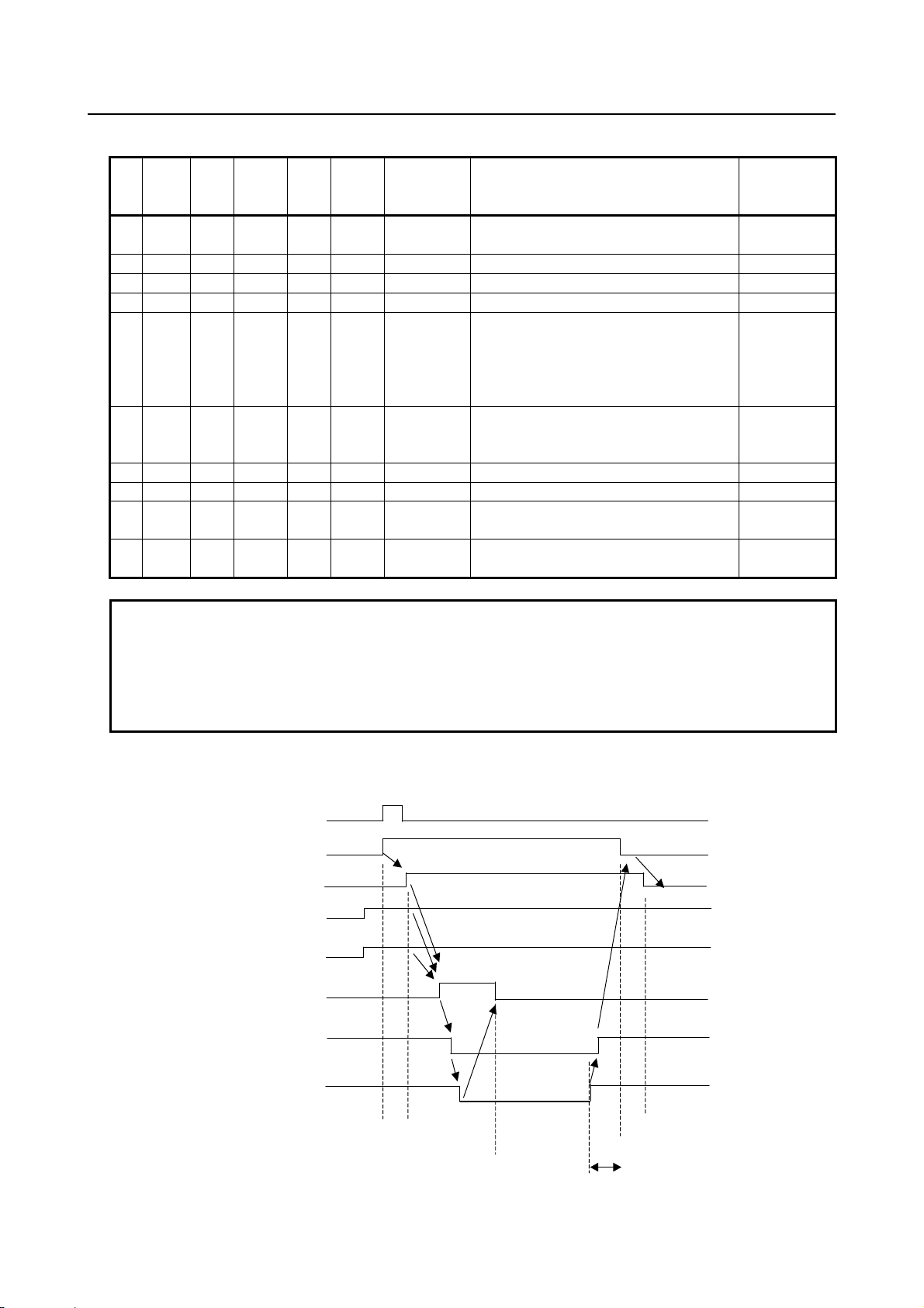
input
output
1 No.11950 No.11970
2 No.11951 No.11971
3 No.11952 No.11972
4 No.11953 No.11973
5 No.11954 No.11974
6 No.11955 No.11975
7 No.11956 No.11976
8 No.11957 No.11977
1 No.11960 No.11980
2 No.11961 No.11981
3 No.11962 No.11982
4 No.11963 No.11983
5 No.11964 No.11984
6 No.11965 No.11985
7 No.11966 No.11986
8 No.11967 No.11987
Signals other than safety-related I/O
The following signals are not safety-related signals (are not checked in redundant mode) but are important
signals in the dual check safety system. The machine tool builder must create an appropriate Ladder
program with these signals.
IMPORTANT
The error of ladder program cannot be checked by safety function itself. Please
make sure to check safety function (see Chapter 7).
10. *OPIHB Guard Open Inhibit signal (output)
When the Guard Open Request signal (ORQ) is input to “1”, the CNC sets this signal. The machine tool
builder must design the PMC ladder logic by this signal. The ladder must confirm safety machine position
and safety speed. If the result of confirmation is judged safe, the ladder turns on the signal to release
guard lock and outputs the signal to open the actual protective door.
If the protective door is unlocked (*SGOPN becomes “0”) while the signal is set to 0, the ladder must
notify alarm occurrence to an operator by lighting a lamp or so on and bring the motor into the safe stop
state.
NOTE
This signal is not output while MCC off Test is executing.
11. RSVx, RSPs Monitoring Result signal (output)
These signals show the result of monitoring safety machine position and safety speed of each axis and the
result of monitoring safety speed of each spindle. When Guard Open Inhibit signal (*OPIHB) is set to “1”,
a machine tool builder can judge whether the machine is in the safety state or not according to these
signals. If safety is confirmed as a result, turn on the signal to unlock the guard lock and output the signal
to open the actual protective door.
- 17 -
Page 28
3.SAFETY FUNCTIONS B-64483EN-2/01
12. POSEx Position Information Effect signal (output)
This signal is output when Dual Check Safety Function is effective and the reference point is established.
When the reference point is not established, the machine system is in danger state because Safety
Machine Position Monitoring and Safety Position Error Monitoring are not active. If this signal is “0”,
Machine Tool Builder has to control not to open the protective door.
13. ORQ Guard Open Request signal (input)
When this signal is input, the CNC set the Guard Open Inhibit signal (*OPIHB) to “1” (Guard open
accept). The PMC ladder program of a machine tool builder confirms the safety machine position and the
safety speed. If both machine position and speed are judged within safe range according to the result of
confirmation, the guard unlock signal is set to 1 (guard unlock enabled). The machine tool builder must
provide an output signal that opens the actual protective door through the PMC.
14. OPT Test Mode signal (input)
When the signal is input, a MCC off Test is executed. The MCC off Test checks whether the contact of
the MCC is abnormally closed. When carrying out the MCC off Test manually, input this signal after the
preparation of a MCC off Test is completed.
15. RQT MCC Off Test Execution Request signal (output)
If the execution of a MCC off Test is required, this signal is output. At power-on, this signal is always
output. If this signal is output, a MCC off Test must be executed.
16. STBT Brake Test Start signal
This signal is used to start or resume a brake test. When the brake test is completed successfully, the
Brake Test Execution Request signal RQBT is set to "0", causing the state of this signal to change from
"1" to "0" as well.
Changing the state of this signal from "1" to "0" during the brake test causes the test to be interrupted. In
that case, the test ends as soon as the test sequence being executed is completed when the signal is set to
"0".
17. RQBT Brake Test Execution Request signal
This signal is used to request a brake test. If the signal is set to "1", please execute the brake test. Even if
this request signal is set to "1", the operation is allowed to continue until the current stage of machining is
completed. To ensure safety, however, when the current stage of machining is completed, be sure to start
a brake test by setting the Brake Test Start signal STBT to "1".
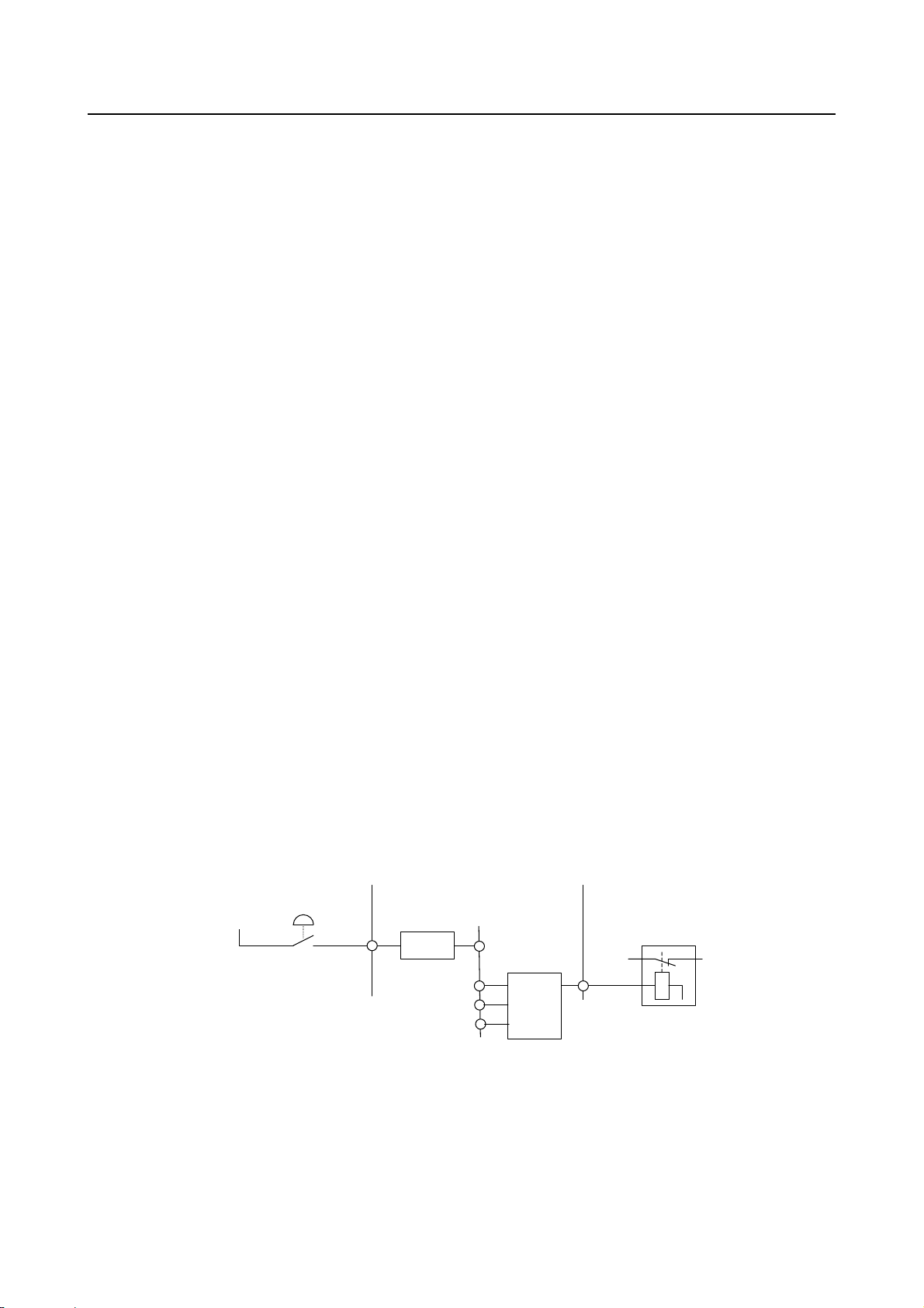
Guard Open Request signal and Guard Unlock signal
Door open request
24V
X
ORQ-I
The figure shows a sample connection of the protective door open request switch and the guard unlock
signal. In the normal state, the door lock state is changed as follows before the safety monitoring state is
established.
Ladder
CNC(PMC)
*OPIHB
RSVx
RSPx
POSEx
F
F
F
G
ORQ
Ladder
Y
Protective
door lock
Protective door
- 18 -
Page 29
B-64483EN-2/01 3.SAFETY FUNCTIONS
A
A
Door lock state transition
ORQ-I ORQ
A
0 0 0 Locked A protective door open request is not
B
1 0 0 Locked A guard open request is made.
C1
1 1 0 Locked The request is transferred to the CNC.
C2
1 1 1 Locked The CNC receives the request.
D
1 1 1 1 1 Locked Reference point is established and a safe
E
1 1 1 1 1 Unlocked
D
1 1 1 1 1 Locked The door is closed and locked again.
F
0 1 1 1 1 Locked The guard open request is canceled.
G
0 0 1 1 1 Locked The CNC is notified of the release of the
A
0 0 0 Locked The CNC receives the release of the
*OPIHB RSVx
RSPs
POSEx
NOTE
The PMC ladder must be designed to monitor whether the protective door is
open (*SGOPN is set to 0) while ORQ is set to 0. If the door open is detected,
the PMC ladder judges that an abnormal event has occurred and enters the safe
stop state. This can occur, for instance, when the door happens to open (or to be
unlocked) while machining is in progress with the protective door closed.
Protective
door lock
(*SGOPN)
(*SGOPN=0)
made, and the door is locked.
speed check, a machine position check
and a position error check prove that there
is no failure and that the CNC can enter
the safe state.
The actual safety door is unlocked.
Operations can be performed with the
door open.
above request.
above request.
Normal
operating state
Safety function
is enabled.
Timing diagram from door close state to door open state
The following diagram shows the timings at which the door is opened and closed again.
ORQ_P
ORQ
*OPIHB
RSVx
RSPs
POSEx
ctual door unlock signal
*SGOP N
(Safety related
I/O signal)
ctual door unlock signal
Door closed
Door opened
(1) (2) (3) (4)
t
Door closed
(5)
- 19 -
Page 30

3.SAFETY FUNCTIONS B-64483EN-2/01
(1) When the Guard Open Request signal (ORQ) is input, the CNC returns the answer signal (*OPIHB)
to PMC.
(2) The PMC ladder program checks that the machine position, speed and position error are within safe
ranges by the Monitoring Result signal (RSVx/RSPs) and the reference point is established by the
Position Information Effect signal (POSEx). Then, it turns on the guard unlock signal.
This example assumes that the protective door has an electromagnetic lock mechanism. While the
door is open, the unlock signal is turned off.
(3) The door is open.
(4) The protective door is closed and locked. After this, the Guard Open Request signal (ORQ) must be
turned off.
(5) When the Guard Open Request signal (ORQ) is turned off, the CNC turned off the answer signal
(*OPIHB).
(Caution)
(Caution)
CAUTION
1 The RSVx and RSPs are redundant and output to both PMCs (PMC and
DCSPMC). Since the RSVx and RSPs signals, the monitoring results of two
independent circuits, are output to two PMCs, the output states of the results
may not match temporarily (when, for example, the spindle speed is close to the
safe speed). Therefore, keep the following in mind when only RSVx and RSPs
are used as conditions for releasing a guard lock. Confirm that RSVx and RSPs
of the PMCs (PMC and DCSPMC) are both placed in the safe state before
releasing a guard lock. When RSVx and RSPs of one PMC are used as
conditions for releasing a guard lock, keep in mind that, before releasing a guard
lock, wait until the speed becomes low enough after RSVx and RSPs enter the
safe state.
When the protective door is assumed to be open if RSVx and RSPs of only one
PMC enter the safe state, a safe speed limit monitoring alarm may occur
depending on the result of the other monitoring state.
2 Ensure a time of 100 ms or longer (“t” in the figure) from when the door is closed
(locked) until the Guard Open Request signal (ORQ) goes off. If this time
requirement is not satisfied, an alarm may be raised when the door is closed
(locked).
Design an operator panel to inform an operator that Guard Open Request signal
(ORQ) is turned on by lighting a lamp.
3.5 EMERGENCY STOP
The Emergency Stop signal is monitored in redundant mode. When the emergency stop is input, the servo
motor slows down to a stop
(Caution)
as instructed by the PMC (Ladder program), and then the power is shut off.
CAUTION
To enable the function to slow down and stop the servo motor, the
corresponding parameter must be specified. If the parameter is not specified, the
motor immediately enters the dynamic brake stop state.
The spindle motor slows down and stops as instructed by the PMC (Ladder
program). If the PMC does not instruct this, the motor maintains the high speed
prior to the power-down and coasts. If an illegal speed is specified because of a
failure on the PMC side while the safety function is active (the protective door is
open), the CNC enters the safe stop state.
(Caution)
and enters the dynamic brake stop. The spindle slows down to a stop
- 20 -
Page 31

B-64483EN-2/01 3.SAFETY FUNCTIONS
WARNING
In the emergency stop state, the processing to open or close the protective door
depends on the Ladder program created by the machine tool builder. For
example, when the protective door is prohibited from being opened in the
emergency stop state (when, for example, the spindle rotates at a speed not
allowed in situations where the protective door is open, that is a speed
exceeding the safe speed limit), the processing needs to be implemented by the
ladder program.
NOTE
Emergency Stop Button must fulfill the Standard IEC60947-5-1.
3.6 SAFE SPEED MONITORING
If the safe speed range is exceeded while the protective door is open, the dual check safety function
immediately enters the stop state. If each axis or spindle is not stopped, the dual check safety function
enters the safety stop state. For each feed axis and spindle, up to four safe speed ranges can be specified
in safety parameters.
Both the CNC and the SV/SP monitor whether a safe speed is kept on each feed axis and spindle. Limit
speed can be changed by the Safety Speed / Safety Position Selection signals (SVAx/SVBx for feed axis,
SPAs/SPBs for spindle).
Name
Safety speed 1 0 0 No.13821 No.4372
Safety speed 2 1 0 No.13822 No.4438
Safety speed 3 0 1 No.13823 No.4440
Safety speed4 1 1 No.13824 No.4442
When excess limit error is detected, Monitoring Result signal (RSVx/RSPs) is set to “0”. In this situation,
if Safety Check Request signal (*VLDVx/ *VLDPs) is “0” and safety monitor is executed, an alarm is
generated.
Error detected CPU Alarm
CAUTION
1 When an illegal speed is detected for the servo axis, if the axis is not stopped
after the time specified in the parameter, the MCC Off signal (*MCFVx) is turned
to “0”.
2 When an illegal speed is detected for the spindle axis, CNC checks whether the
spindle speed decelerates continuously or not. If acceleration is detected, the
MCC Off signal (*MCFPs) is turned to “0”.
3 For the spindle, bit 1 (CTLSTP) of parameter No. 4399 can be used to select a
stop method (free run stop or controlled stop) on occurrence of a safe speed
excess alarm.
Safety Speed/Safety Position Selection signal Safety speed parameter
SVAx/ SPAs SVBx/ SPBs Feed axis Spindle
CNC SV0494/SP0757
SV SV0476
SP SP9069(SPINDLE ALARM 69)
- 21 -
Page 32

3.SAFETY FUNCTIONS B-64483EN-2/01
IMPORTANT
1 A gear ratio, ball screw, and the like must be carefully selected so that a safe
speed can be kept on the feed axis.
2 Before inputting the Guard Open Request signal (ORQ), reduce each axial
speed and spindle speed to a safe speed range or below. If a speed exceeds the
limit, do not unlock the protective door. The PMC ladder must be designed that
the power to the driving circuit is shut off (safe stop state) if the door is forced
open.
WARNING
The safe speed monitoring function monitors whether the traveling speed
exceeds a specified limit. The function cannot monitor the stop state (zero
speed). If an error causes a movement on the feed axis at a speed lower than
the safe speed range while the protective door is open, for instance, the function
cannot detect this state. The machine must be designed so that this state does
not affect the safety of the machine system.
3.7 SAFE MACHINE POSITION MONITORING
While the door is open, the dual check safety function checks whether the position on each feed axis is
within the safe machine position range defined by safety parameters. If it detects a machine position
beyond the safety range, the dual check safety function immediately enters the stop state. If each axis is
not stopped, the dual check safety function enters the safety stop state.
For each feed axis, up to four safe positions can be specified in safety parameters.
Both the CNC and the Servo monitor whether each axis is within the safety position. The range of the
safety machine position can be changed by the Safety Speed / Safety Position Selection signals
(SVAx/SVBx for feed axis).
Safety Speed/Safety Position Selection
Name
SVAx SVBx + direction - direction
Safety machine position 1 0 0 No.13831 No.13832
Safety machine position 2 1 0 No.13833 No.13834
Safety machine position 3 0 1 No.13835 No.13836
Safety machine position 4 1 1 No.13837 No.13838
When “out of position error” is detected, Monitoring Result signal (RSVx) is set to “0”. In this situation,
if Safety Check Request signal (*VLDVx) is “0” and safety monitor is executed, an alarm is generated.
This monitoring function is vaid after the reference position is established.
Error detected CPU Alarm
CNC SV0495
SV SV0477
signal
Safety machine position parameter
CAUTION
1 The safe machine position monitoring function does not keep monitoring the
specified range. Only after the function detects that a position on a feed axis
exceeds the range, the system enters the stop state. Accordingly, in the stop
state, an over travel has occurred on the feed axis. The travel distance depends
on the traveling speed and other conditions.
- 22 -
Page 33
B-64483EN-2/01 3.SAFETY FUNCTIONS
CAUTION
2 When an “out of position error” is detected, if the axis is not stopped after the
time specified in the parameter, the MCC Off signal (*MCFVx) is turned to “0”.
The user of the machine must first carry out a reference position return in order to obtain the initial
position. If the reference position return is not carried out, the check function is disabled. This check
function is enabled after the reference position is established. (The function cannot be disabled by any
means after the reference position is established.)
CAUTION
A machine operator must confirm whether the machine reference position is
established correctly by checking the actual machine position and position
display of the CNC.
While power-on, the safety function does not work. After power-on, the CNC checks whether a reference
position return is completed. If the reference position return is completed and if the protective door is
open, safe machine position monitoring, safe speed monitoring and safety position error monitoring are
performed. Then, the safety functions start working. If the reference position return is not completed, safe
machine position monitoring cannot be performed because the coordinates are not established. In this
state, the machine position monitoring function is disabled. After a reference position return is made, this
function is enabled. Depending on the safety parameter setting, however, an alarm may occur. To avoid
this alarm, set the safe machine position parameters before making a reference position return.
CAUTION
1 The machine coordinate of the safety function is based on position feed back. So
it does not always indicate the same value as the machine coordinate based on
the summation of the command value.
2 This function is activated only in position control mode.
3.8 MCC OFF TEST
A MCC off Test must be carried out in intervals of 24 hours, so that the safety functions would not be
damaged by an accumulation of failure. A warning message is displayed that the MCC off Test must be
carried out at power-on or when 24 hours have elapsed after the previous MCC off Test. The machine
tool builder must set up the machine not to open the protective door before a MCC off Test is not
completed.
A MCC off Test performs the test to turn on and off MCC by controlling *SMC signal in order to confirm
whether the circuit to shut off MCC is normal. The MCC off Test is performed both on PMC and DCS
PMC. If the MCC off Test is not completed within the time specified by the parameter No.1946 (MCC
off Test timer), alarm SV0488 is generated. It is necessary to carry out the MCC off Test before the
protective door is open, when power is on or 24 hours have elapsed after previous MCC off Test.
The PMC ladder program must be designed to carry out the following control.
<1> When MCC off Test request signal (RQT) is set to “1” at power-on or in case 24 hours are elapsed
after the previous MCC off Test, the protective door is locked till the MCC off Test is terminated
normally. But the operator can operate the machine while the protective door is closed.
<2> When the MCC off Test request signal (RQT) is turned to “0”, the protective door can be unlocked.
- 23 -
Page 34

3.SAFETY FUNCTIONS B-64483EN-2/01
*MCF (DCS PMC)
*MCF (PMC)
*SMC (DCS PMC)
*SMC (PMC)
RQT
Example) DO state during MCC off Test
Test No.
Timer limit
Timer
1 2 3 4 5
Test completionTest start
128
Test
number
1 When the *MCF signals on both the PMC and DCSPMC sides are 1, confirm that the MCC is on.
(*SMC = 0)
2 Confirm that the MCC turns off (*SMC = 1) when the *MCF signal on the DCSPMC side is set to 0.
3 Confirm that the MCC turns on (*SMC = 0) when the *MCF signal on the DCSPMC side is returned
to 1.
4 Confirm that the MCC turns off (*SMC = 1) when the *MCF signal on the PMC side is set to 0.
5 Confirm that the MCC turns on (*SMC = 0) when the *MCF signal on the PMC side is returned to 1.
128 This state is entered when tests 1 to 5 end successfully.
Description
IMPORTANT
Carry out the MCC off Test with the protective door closed. As the test shuts off
the MCC, prepare the system for mechanical MCC shut-off before starting the
MCC off Test.
The following describes notes and a timing chart during the MCC off Test.
<1> Before performing the MCC off Test, stop the feed axis and spindle.
<2> When the MCC off Test ends, the MCC Off Test Execution Request signal goes off. After the MCC
Off Test Execution Request signal goes off, set the test mode signal to off.
<3> When the vertical axis is present, take measures such as preparing a brake circuit for drop prevention.
Take 500 ms or more from when the brake is driven until test start signal OPT is activated, in the
ladder.
<4> Do not connect a peripheral device or noise filter between the MCC and the common power supply.
Otherwise, the test may not terminate normally.
<5> Enable the servo off signals (SVF1-8) after applying a brake to the servo axis connected to the
common power supply to be tested. If the servo off signals are not input, an alarm may occur during
the test.
<6> When the power failure backup module is connected, the ready signal (contact output signal RDY)
of the power failure backup module goes off during the MCC off Test. Therefore, make
considerations to eliminate a problem in the ladder. A possible measure is to mask the ready signal
by the test mode signal.
- 24 -
Page 35

B-64483EN-2/01 3.SAFETY FUNCTIONS
[Timing chart of the MCC off Test]
MCC off Test start
(Signal from the user)
Vertical axis brake
(Signal from the user)
During a test
Brake on
Test mode signal
OPT <Gn191.2>
Servo off signal
SVF8 to 1<Gn126.7 to 0>
MCC Off Test Execution
Request signal RQT
<Fn191.2>
Power failure backup module ready signal
RDY (contact output)
500 ms or more
During the MCC off Test
Contact on
Contact off
3.9 SAFETY POSITION SWITCH FUNCTION
It is checked whether the machine position is within the range of safety position switch. The checked
result is outputted to the Safety Position Switch signal. The correspondence between axes and each signal
is specified by the parameters. In case of 1 path system, up to 32 points can be specified. And in case of 2
or more paths, up to 64 points can be specified.
When a machine position of controlled axis is within a range, which is specified by the safety parameters,
this signal is output.
1
0
Parameter setting
value
Parameter setting
value
The signals are output after establishment of the reference position. The signal is not output before the
completion of reference position return.
The “machine position” is the actual machine position (which is calculated using feedback of position
detector), not the commanded position.
The comparison of position for safe position switch is executed in detection unit.
If the machine position equals parameter setting value, the safe position switch signal is output.
The safe position switch signal is not output for axis which the Dual Check Safety (bit 6 (DCN) of
parameter No. 1904 = 1) is not applied to.
Safety Position switch can be assigned up to 16 points per 1 group to the output signal (F signal) and
totally up to 4 groups 64 points can be used in the CNC system. Two areas per a path are provided to
assign. It is possible to assign the group to an appropriate area.
- 25 -
Page 36

3.SAFETY FUNCTIONS B-64483EN-2/01
A
A
The assignment of controlled axes is set by the safety parameters (No.13880 to No.13911, No.10501 to
No.10532). Safe position switch signals can be assigned to arbitrary controlled axes. All points can be
also assigned to one axis.
And the signals can be also assigned to the rotary axes.
When inconsistency between the position switch on PMC and that on DCS PMC is lasted for the time that
is specified by the parameter No.1945, the safety function sets MCC Off (signal *DCALM to “0”) and
generates the alarm “safe I/O cross check error” (PW0010/PW0011) .
NOTE
The machine coordinate of the safety function is based on position feed back
which is affected by mechanical factor. So it does not always indicate the same
value as the machine coordinate based on the summation of the command
value.
Two machine coordinates that are calculated by two CPU independently are not
always the same because the position feedback is continuously changed a little.
As there is a possibility that the condition of two signals is different from each
other near the boundary, please avoid usage to stop an axis near the boundary.
CAUTION
This function is activated only in position control mode.
• Hysteresis
Around the position switch boundary, the Safety Position Switch signal may repeatedly turn on and
off due to motor vibration. Since this condition is not convenient for using this signal, the concept of
hysteresis is applied as follows.
Minimum limit of
position switch
Maximum limit of
position switch
Width of hysteresis Width of hysteresis
ctivated area of position switch
Fig.3.9(a) Activated area of the position switch when the Safety Position Switch signal is set to "0"
Minimum limit of
position switch
ctivated area of position switch
Fig.3.9(b) Activated area of the position switch when the Safety Position Switch signal is set to "1"
Maximum limit of
position switch
Suppose that the minimum limit and maximum limit of the position switch are represented by an area like
those shown above. If the value of the Safety Position Switch signal used for the last measurement is "0",
then the check is made in an area that takes into account the width of hysteresis (Fig. 3.9 (a)). If the value
of the last used Safety Position Switch signal is "1", then the check is made in an area that does not take
into account the width of hysteresis (Fig. 3.9 (b)). This reduces the fluctuation in the Safety Position
Switch signal.
- 26 -
Page 37

B-64483EN-2/01 3.SAFETY FUNCTIONS
3.10 SAFETY RELATED PARAMETERS CHECK FUNCTION
At every power-on, the CNC checks whether the safety related parameters are destroyed and are
transferred to the SV, the SP and the PMC normally or not. The SV, the SP and the PMC also check
whether the safety related parameters are transferred from the CNC normally or not.
If some problem is found in this check, an alarm is generated and the MCC is shut off. (*DCALM=0)
3.11 PARAMETER LOCK FUNCTION
It is possible to lock the rewriting of the safety related parameters.
The parameter No.3225 and No.3226 lock/unlock these parameters. The following parameters are locked.
No.980, No.981, No.982, No.1023, No.1240,No.1838, No.1839, No.1840, No.1841,No.1842,
No.1902#6,No1904, No.1945, No.1946, No.1948, No.1950, No.2000, No.2023, No.2024, No.2084,
No.2085, No.2185, No.3021,No.3022,No.3225,No.3717, No.3797, No.4372, No.4438, No.4440,
No.4442, No.4448, No.4545, No.10500-No.10596, No.11950-No.11957, No.11960- No.11967,
No.11970-No.11977, No.11980-No.11987, No.13806, No.13811, No.13821-No.13829,
No.13831-No.13838, No.13840-No.13843, No.13880-No.13911 , No.13912-No.13919,
No.13920-No.13951, No.13960-No.13991
3.12 SEFETY POSITION ERROR MONITORING FUNCTION
Both the CNC and the SV check whether the servo position error of each axis exceeds the limit of
deviation specified by the parameters. If the servo following error exceeds, an alarm is generated and
MCC OFF signal (*MCFVx) is output immediately.
The relation between the safety monitoring state and the parameter of limit of deviation is shown in the
following table.
Safety monitoring is activated
(In case *VLDVx =0)
Moving No.1838 No.1841
Stopping No.1839 No.1842
Servo-off No.1840 No.1840
Error detected CPU Alarm
CNC SV1072/SV1071/SV1069
SV SV0474/SV0475/SV1070
When position deviation exceeds the limit given by the parameter (No.1839 in stop state, No.1838 in
moving state and No.1840 in servo off state) during safety monitoring, Monitoring result signal RSVx is
set to “0” regardless of the state of Safety check request signal *VLDVx.
This function is valid after the reference position return is finished or the follow-up of absolute position is
finished in case an absolute position coder.
CAUTION
This function is activated only in position control mode.
Safety monitoring is not activated
(In case *VLDVx =1)
- 27 -
Page 38

3.SAFETY FUNCTIONS B-64483EN-2/01
3.13 AMPLIFIER CIRCUIT MONITORING FUNCTION
The SV and the SP transmit the data of plural axes to amplifiers through one electronic circuit (LSI). The
CNC, the SV and the SP check whether this transmission is performed normally without placing data on
wrong address.
In case of servo amplifier, the CNC axis numbers kept by the CNC are compared with the CNC axis
numbers kept by the SV. In the case of the spindle amplifier, the spindle numbers kept by the CNC are
compared with those kept by the spindle amplifier. The checking sequence is as follows.
[Checking sequence for servo amplifier]
<1> When a servo amplifier is set up at the first time, an alarm SV0498 is generated. At that time, the
CNC transfers the CNC axis numbers to the SV and the SV keeps the data. Then the power of all
CNC system (amplifiers are included) must be turned off and on.
When an alarm is generated after the configuration of servo amplifiers is changed, it is necessary to
carry out the operation to send the CNC axis numbers to servo amplifiers. Set the parameter
No.2212#4 to “1” then return to “0”. Then turned off the power of all CNC system (amplifiers are
included.)
<2> After the power-on, the CNC and the SV start monitoring the CNC axis numbers. The CNC
monitors by comparing the CNC axis number kept by the CNC itself with that kept by the SV. The
SV monitors by comparing the CNC axis numbers kept by the SV with that sent by the CNC.
When some error is found, an alarm SV0478 or SV0496 is output, and MCC Off signal (*DCALM)
is turned to “0”.
[Checking sequence for spindle amplifier]
<1> When a spindle amplifier is set up for the first time, alarm SP9148 is generated. During this process,
the CNC transfers the spindle numbers to the spindle amplifier, which in turn keeps those numbers.
When this occurs, the power of the entire CNC system (including the amplifier) must be turned off
and then back on.
If an alarm is generated because the configuration of the spindle amplifier is changed, it is necessary
to send the spindle numbers to the spindle amplifier (set bit 7 of parameter No. 4541 to "1", then set
it back to "0", and then turn off the power of the entire CNC system (including the amplifier)).
<2> The CNC compares the spindle numbers kept by the CNC itself with that sent from spindle amplifier.
If inconsistency is found, an alarm SP0756 is output and MCC Off signal (*DCALM) is turned to
“0”.
<3> The SP compares the spindle numbers with that kept by the spindle amplifier. If inconsistency is
found, alarm SP9070 (Spindle alarm 70) is output, and MCC Off signal (*DCALM) is turned to “0”.
3.14 SAFETY BRAKE SIGNAL OUTPUT FUNCTION
The CNC and the SV output the Safety Brake signal (*BRKx) to control the mechanical brake. When this
signal is “0”, mechanical brake must be activated. When this signal is “1”, mechanical brake is allowed to
be released.
When the inconsistency between the break signal on PMC and that on DCS PMC is lasted for the time
that is specified by the parameter No.1945, the safety function sets MCC Off signal (*DCALM) to “0”
and generates the alarm “safe I/O cross check error” (PW0010/PW0011).
- 28 -
Page 39

B-64483EN-2/01 3.SAFETY FUNCTIONS
3.15 CPU SELF TEST FUNCTION
The CNC, the PMC, the SV and the SP carry out the following self-diagnosis. If the error is detected, the
alarm is generated and sets MCC Off signal (*DCALM) to “0”.
<1> CPU check
It is checked whether each CPU runs normally or not.
It is checked whether the instructions related to safety function is executed normally or not.
Error detected CPU ALARM
CNC PW0014
PMC PW0009
SV SV0484
SP SP9074 (Spindle alarm 74)
<2> Program flow monitoring
It is confirmed whether all safety related function run normally.
Error detected CPU ALARM
CNC PW0017 / SV0490
PMC PW0008 (DCS PMC), PW0009 (PMC)
SV SV0484
SP SP9076 (Spindle alarm 76), SP0755
<3> Cross check
It is checked whether the result of the judgment about the safety related function of a CPU is
consistent with that of another CPU.
If some error is found, an alarm is output.
ALARM
SV relation SV0490/SV0484
SP relation SP9072 (Spindle alarm 72),
SP9077 (Spindle alarm 77),
SP9078 (Spindle alarm 78),
SP0755
PMC relation PW0008 (DCS PMC), PW0009 (PMC)
3.16 RAM CHECK FUNCTION
ECC (Error Check and Correct) function is applied to the battery back-upped file memory. Then a simple
error is corrected. And, when an error that cannot be corrected occurs, an alarm is generated.
Other memory for dual check safety is checked as follows. If the error is detected, the alarm is generated
and sets MCC Off signal (*DCALM) to “0”.
1) Test at power-on
The several test patterns are written to the RAM area. It is checked whether the written test data are
read correctly. If read error occurs, an alarm is generated.
2) Test during normal operation
RAM area is checked sequentially at constant interval during normal operation. The several test
patterns are written to the RAM. It is checked whether the written test data are read correctly. If read
error occurs, an alarm is generated.
Alarm detected CPU Alarm
CNC PW0016
- 29 -
Page 40

3.SAFETY FUNCTIONS B-64483EN-2/01
Alarm detected CPU Alarm
SV SV0484
PMC PW0008 (DCS PMC), PW0009 (PMC)
SP SP9016 (Spindle alarm 16)
3.17 CRC CHECK FUNCTION
At power-on and after power on, the data that are related to Dual Check Safety and stored in the ROM
area are checked. The CNC software, the servo software, the PMC software and the spindle software are
checked. If some error is found, an alarm is generated.
After power on
Error detected Software Alarm
CNC software CRC CHECK ERROR: NC BASIC.
Servo software SERVO ROM TEST: CRC CHECK ERROR
PMC management software LED “6”
Spindle software Spindle alarm 75
After power on
Error detected Software Alarm
CNC software PW0018 CRC CHECK ERROR
PMC management software SYS-ALM199 NON MASK INTERRUPT OTHER-CPU
3.18 SAFE STOP MONITORING
When a safety door is open, safe stop monitoring for servo axis and spindle can be realized by the
combination of several functions.
Safe stop monitoring for servo axis
According to the safe speed monitoring for servo axis and the safe positing error monitoring, CNC and
Servo monitor actual feedrate and deviation of each axis. When a safety door is open, monitoring of stop
condition of each axis can be performed by the combination of the following three functions.
a) By the safety speed monitoring function, check whether the actual feed rate is lower than the safety
level. If the feedrate exceeds the safety limit, an alarm is generated.
Actual speed is calculated with the feedback of a position detector. So, even if command feedrate is
0, actual feedrate may be detected as not 0 when an axis is moved by external power. Set the value
of safety limit that does not cause an alarm when feedrate command is 0.
b) By the safe positioning error monitoring function, check whether position deviation is within a
safety limit. If an axis is moved unexpectedly, an alarm is generated.
c) According to “Axis moving signal MVx <Fn102>”, check whether axis motion command is not
given. (Axis moving signal is prepared for PMC and is not double check signal.)
Safe stop monitoring for spindle
In monitoring of the safe speed limit of the spindle, the actual speed of the spindle motor is monitored at
the CNC and spindle. When a safety door is open, monitoring of stop condition of each spindle can be
performed by the combination of the following two functions.
a) By the safety speed monitoring function, check whether the actual speed is lower than the safety
level. If the feedrate exceeds the safety limit, an alarm is generated.
Actual speed is calculated with the feedback of a position detector. So, even if command speed is 0,
actual speed may be detected as not 0 when a spindle is moved by external power. Add the machine
oriented margin to the value of safety limit that does not cause an alarm when speed command is 0.
- 30 -
Page 41

B-64483EN-2/01 3.SAFETY FUNCTIONS
b) There is a possibility that spindle rotate at speed lower than safety speed limit. Then it is necessary
to select the function to make position control loop, such as spindle positioning, Cs contouring
control or spindle orientation.
3.19 BRAKE TEST
To ensure the safety of the brake, the brake signals (*BRKx) that are output in redundant mode are used
to control the brake of the servo axis mechanically. To ensure the safety of this control, a periodical test is
performed on the servo axis brake.
Remaining risks
This function has the following remaining risks.
If the brake fails in a vertical axis without a redundant brake mechanism between the current brake test
and the next, the axis may drop when the servo motor is deactivated due to an emergency stop or servo
alarm.
Specifications
A brake test can be performed on servo axes that have a brake. The test needs to be done only on those
axes that require brake control, such as vertical axes. Whether to perform the test can be selected on an
axis-by-axis basis using a parameter. As with the MCC shut-off test, the brake test is performed when the
power is turned on or when time t has elapsed since the last test (t is the value set in parameter No.
13913).
Getting started with the brake test
(1) When the power is turned on or when time t has elapsed since the last brake test (t is the value set in
parameter No. 13913), the Brake Test Execution Request signal RQBT (DO) is set to "1". When this
signal is set to "1", execute a brake test. Even when the request signal is turned on, the operation is
allowed to continue until the current stage of machining is completed. To ensure safety, however,
execute a brake test as soon as possible.
(2) Clear all NC alarms, switch to the JOG mode, and then retract the axis eligible for the brake test to a
safe position.
(3) To start the brake test, turn on the Brake Test Start signal STBT (DI).
NOTE
Since the test involves giving the move command to the servo motor, make sure
it is performed in position control mode in the servo on state. The test will not be
executed if the axis to be tested is in a mode other than the position control
mode (velocity control or torque control) or in the servo off state or if the torque
limit mode. An alarm is generated if the conditions are not satisfied.
Executing the brake test
(1) When the brake test execution request mentioned above is accepted, all the axes eligible for the
brake test are tested simultaneously. Using combinations of states of two brake signals *BRKx
(PMC side and DCSPMC side), three different tests are executed per axis in the order shown below.
*BRKx(PMC) 0 0 1
*BRKx(DCSPMC) 0 1 0
Brake state Applied Applied Applied
Test 1 Test 2 Test 3
- 31 -
Page 42

3.SAFETY FUNCTIONS B-64483EN-2/01
Ending the brake test
(1) When all the axes are tested successfully, the Brake Test Execution Request signal RQBT is set to
"0".
If any error occurs during the test, an alarm is generated. While the servo motor remains activated
even in an alarm state, the automatic operation cannot be continued. In that case, retract the axis to a
safe position manually, turn off the power, and take action to solve the problem of the brake in
question.
Before executing the brake test again, reset the system to clear the alarm state.
(2) When the test ends normally, set the Brake Test Start signal STBT to "0".
Test Start signal
(DI:STBT)
Test Execution Request signal
RQBT)
:
Under test
Not under test
(DO
*BRKx(DCSPMC)
*BRKx(PMC)
Test sequence
1
0
1
0
1
0
1
0
Test 1 Test 2 Test 3
Fig. 3.19 (a) Overall time chart
NOTE
1 Execute the test in the servo on state.
2 The amount of travel, feedrate, and positional deviation value must be set in
advance using parameters.
3 Make sure that the protective door is closed when the test is executed. To
ensure safety, create a ladder program that prohibits the protective door from
being opened, even if a protective door open request is issued, until the break
test is executed when the Brake Test Execution Request signal RQBT is turned
on after time t has elapsed (t is the value set in parameter No. 13913).
4 Do not execute the test with the protective door open. Create a ladder program
that prohibits the Brake Test Start signal STBT from being turned on so that the
test cannot be executed while the protective door is open.
5 The brake test cannot be executed on axes subject to feed axis synchronization
control or synchronous, composite, or superimposed control. Before executing
the test, be sure to turn off the relevant selection signal.
6 If the brake test causes an alarm, the axis can be moved manually, while the
automatic operation cannot be continued unless the alarm is cleared by the
reset. Make sure that the automatic operation is performed in a safe condition. If
the brake test is interrupted due to an alarm or for some other reason, the axis
may not be able to be returned to its original position.
7 The override for the feedrate command is fixed at 100%, and the dry run and
rapid traverse signals are disabled.
8 The interlock and machine lock states are effective during the brake test.
- 32 -
Page 43

B-64483EN-2/01 3.SAFETY FUNCTIONS
CAUTION
The axis may move during the brake test. Before the test, move the axis to a
safe place where it does not interfere with any other part.
Details of each brake test
Details of the tests
Tests 1, 2, and 3 check whether the brake is applied normally and involve the following operations.
(a) Brake signals *BRKx are output according to the test step to be executed. The torque limit value of
the axis subject to the brake test is used as the torque limit value for the brake test. The torque limit
value can be set using a parameter.
(b) The NC waits for t1 (t1 is the value set in parameter No. 13914) until the brake is applied and the
command can be issued.
(c) Next, the NC outputs the position command according to the amount of travel and feedrate set in
parameters.
(d) After issuing the command, the NC checks the positional deviation amount in order to determine
whether the brake is applied normally. If the brake is applied normally, the axis has not been moved
and there is accumulated positional deviation equivalent to the specified amount of travel. The range
of the positional deviation amount to be checked is equal to the corresponding positional deviation
amount plus and minus the tolerance value (the value set in parameter No. 13918). The time during
which the NC checks whether the brake is applied normally is specified by t2 (t2 is the value set in
parameter No. 13919). If the positional deviation amount is outside the range, the NC regards the
brake as failing to be applied normally and generates an alarm.
(e) After the check, the NC issues a command to reset the accumulated positional deviation amount.
(f) Before executing the next test, the NC waits for t1 (t1 is the value set in parameter No. 13914).
Torque limit
*BRKx(PMC,
DCSPMC)
Command
(POS)
Error monitoring
Enable
Disable
+
Command
No command
-
Command
Monitored
Not monitored
Current test
1
0
t1
(a)
(b) (c)
Command
(travel
amount/feedrate)
t2
(d)
Fig. 3.19 (b) Brake test time chart
Cancel
command
(e)
t1
(f)
Next test
Interrupting and resuming the brake test
• Changing the state of the Brake Test Start signal STBT from "1" to "0" during the brake test causes
the test to be interrupted. The test sequence being executed when the signal is set to "0" is suspended,
and the amount of travel occurring during the brake test, brake signals, and torque limit are reset. To
execute the brake test again, set this signal to "1". The brake test will resume from the beginning.
- 33 -
Page 44

3.SAFETY FUNCTIONS B-64483EN-2/01
• If the brake test is interrupted by an emergency stop or servo alarm, the test is forced to end even
during a test sequence. After the servo motor is activated by the reset process, the brake signals and
torque limit are reset. Also, make sure that, during the brake test, the servo ready signal SA
<Fn000.6> is monitored in addition to the brake signals to control the brake. To execute the brake
test again, set this signal to "0" and then to "1". The brake test will resume from the beginning.
• If the brake test is interrupted due to the reset or mode change, the test sequence being executed is
suspended, while the brake signals and torque limit are not reset, leaving the test as it is when it is
interrupted. To reset the amount of travel occurring during the brake test, brake signals, and torque
limit, set the Brake Test Start signal STBT to "0" and then to "1". After all these interruption
operations are complete, it becomes possible to execute the brake test again.
- 34 -
Page 45

B-64483EN-2/01 3.SAFETY FUNCTIONS
Brake configuration
This function assumes the brake configuration shown in either Fig. 3.19 (c) Brake configuration - 1 or Fig.
3.19 (d) Brake configuration - 2.
CNC (30i)
PMC
JD51A
DCS
PMC
I/O Link
Channel 1
I/O Link
signal divider
JD44A-1
JD51B
JD1A
I/O Link
Channel 3
I/O Module 1
I
JD1B
O
I/O Module 2
I
JD1B
O
*BRKx
*BRKx
RL
0V
RL
0V
built-in
motor
brake
24V
M
CNC (30i)
PMC
JD51A
DCS
PMC
I/O Link
Channel 1
I/O Link
signal divider
JD44A-1
JD51B
JD1A
I/O Link
Channel 3
Fig. 3.19 (c) Brake configuration - 1
I/O Module 1
I
O
I
O
*BRKx
RL
0V
External
brake
*BRKx
RL
0V
JD1B
I/O Module 2
JD1B
Fig. 3.19 (d) Brake configuration - 2
24V
0V
0V
built-in
motor
brake
24V
M
0V
Example in which signals are connected using a
two-channel I/O Link
(For details about connections, see Chapter 4,
"INSTALLATION".)
- 35 -
Page 46

4.INSTALLATION B-64483EN-2/01
4 INSTALLATION
The hardware installation such as field wiring, power supply, etc. should be referred to connection
manual for CNC units and for servo amplifier. EMC problem should be referred to EMC guideline
manual.
As for the environmental conditions for each unit, such as CNC controller, servo amplifier and etc, please
refer to each connection manual.
Degree of IP protection:
Servo Motors: IP55
Spindle Motors: IP54 with oil-seal, IP40 without oil-seal
Servo and Spindle amplifiers: IP1x
CNC and other accessories: IPxx
The peripheral units and the control unit have been designed on the assumption that they are housed in
closed cabinets.
CAUTION
Servo/Spindle amplifiers, CNC are to be installed in IP54 protected cabinets.
I/O connection configuration
The Dual Check Safety function uses two-channel I/O configuration.
The safety-related I/O signals are connected via separate paths (Note 1) to two I/O modules that are
respectively connected to one of the two channels. To build a dual monitoring system, the machine tool
builder needs to connect one of the duplicated safety-related I/O signals to the I/O module connected to
the DCS PMC side and the other to that connected to the PMC side.
CNC
CNC
(DCS PMC)
(Note 2)
I/O Link or
PROFIBUS -DP
(Note 4)
Cross check
PMC
(Note 3)
I/O Link
NOTE
1 I/O Link i allows the safety-related I/O signals of both the PMC and DCS PMC
sides to be connected over a single path.
2 Dual Check Safety PMC (DCS PMC)
3 First PMC to fifth PMC
Refer to PMC PROGRAMMING MANUAL (B-64513EN).
4 Enable broken wire detection for the slave device connected to PROFIBUS-DP
for the safety-related I/O. For details, see Section 6.6, "PROFIBUS-DP
PARAMETER SETTINGS".
I/O
MODULE
I/O
MODULE
DI
DO
DI
DO
Machine side
CNC
CNC
(DCS PMC)
(Note 2)
(Note 1)
Cross check
PMC
(Note 3)
I/O Link i
(Note 1)
DCSPMC side
I/O MODULE
PMC side I/O
MODULE
Machine side
DI
DO
DI
DO
- 36 -
Page 47

B-64483EN-2/01 4.INSTALLATION
Note on the I/O configuration
Of the I/O Link, I/O Link i, and PROFIBUS-DP, only one of them can be assigned to the X/Y area of the
DCS PMC side.
4.1 OVERALL CONNECTION DIAGRAM
4.1.1 In case of using the I/O Link
CNC
Main board
3ch I/O Link
I/O Link(JD51A)
signal divider
JD51B
JD44A-1
JD44A-2
JD1A
I/O Link #1/#2
(General I/O, PMC side safety-related I/O)
Manual pulse generator
Distribution-type
I/O Link #3
(DCS PMC side
safety-related
I/O)
24VDC
24VDC
24VDC
I/O board
CPD1
JD1B
JD1A
I/O UNIT, etc.
CPD1
JD1B
JD1A
I/O UNIT, etc.
CPD1
JD1B
JD1A
JA3
Operator's
panel
Power
magnetics
cabinet
Power
magnetics
cabinet
The above figure shows only the two-channel I/O Link used to input and output the safety-related I/O
signals for the Dual Check Safety function. For information about other types of connection, refer to the
general connection manual.
- 37 -
Page 48

4.INSTALLATION B-64483EN-2/01
4.1.2 In case of using the I/O Link i
CNC
Main board
I/O Link i
(JD51A)
24VDC
I/O Link i
(General I/O, PMC side
safety-related I/O
DCS PMC side safety-related I/O)
Manual pulse generator
Distribution-type
I/O board
CPD1
JA3
Operator's
panel
Power
magnetics
cabinet
Power
magnetics
cabinet
24VDC
24VDC
JD1B
JD1A
I/O UNIT, etc.
CPD1
JD1B
JD1A
I/O UNIT, etc.
CPD1
JD1B
JD1A
(PMC side)
(DCS PMC side)
NOTE
To establish connections using the I/O Link i, the I/O modules and all the other
components to be connected need to support the I/O Link i.
The above figure shows only the l I/O Link i used to input and output the safety-related I/O signals for the
Dual Check Safety function. For information about other types of connection, refer to the general
connection manual.
- 38 -
Page 49

B-64483EN-2/01 4.INSTALLATION
y
4.1.3 In case of using PROFIBUS-DP on the DCS PMC side
CNC
Main board
I/O Link(JD51A)
I/O Link or I/O Link i
(General I/O, PMC side
safet
PROFIBUS-DP
master board
CN1
24VDC
Distribution-type
I/O board
CPD1
-related I/O)
Manual pulse generator
JA3
Operator's
panel
Power
magnetics
cabinet
Power
magnetics
cabinet
PROFIBUS-DP
(DCS PMC side
safety-related
I/O)
24VDC
Power supply
JD1B
JD1A
I/O UNIT, etc.
CPD1
JD1B
JD1A
Slave device
The above figure shows only the I/O Link and PROFIBUS-DP used to input and output the safety-related
I/O signals for the Dual Check Safety function. For information about other types of connection, refer to
the general connection manual.
- 39 -
Page 50

5.I/O SIGNALS B-64483EN-2/01
5 I/O SIGNALS
5.1 OVERVIEW
The Dual Check Safety Function provides two input paths and two output paths for safe-related signals
(safety signals).
Input signals (safety input signals) are input via two paths; one is connected to the CNC (DCS PMC) via
I/O Link channel 3, I/O Link i, or PROFIBUS-DP (Note 1) and the other is connected to the PMC via I/O
Link channel 1/2 or I/O Link i (Note 1). The CNC (DCS PMC) (Note 2) and the PMC (Note 2) constantly
exchange safety input signals with each other and monitor each other. If a mismatch is found between a
safety input signal via one path and the same signal via another path and such a state lasts for the period
set in a parameter or more, the CNC (DCS PMC) and the PMC independently detect an alarm.
(Dual-check for safety input signals)
Output signals (safety output signals) are output via two paths; one originates from the CNC (DCS PMC)
via I/O Link channel 3, I/O Link i, or PROFIBUS-DP (Note 1) and the other originates from the PMC via
I/O Link channel 1/2 or I/O Link i (Note 1). The MCC Off signal (*MCF) is output via these two paths.
The value of this signal is regarded as "1" only when the signals output via the two paths are both set to
"1". If either of them is set to "0", the value of the signal should be regarded as "0". In other words,
turning on the MCC is allowed only when the *MCF signal of the PMC side and the *MCF signal of the
DCS PMC side are both set to "1", and if either of them is set to "0", the MCC needs to be turned off.
Section 5.3 shows the name of the signal, the code representing the signal, and the signal address (<PMC
side> and <DCS PMC side>), as well as the classification, function, and operation (for an input signal) or
the classification, function, and output condition (for an output signal).
NOTE
1 Of the I/O Link, I/O Link i, and PROFIBUS-DP, only one of them can be
assigned to the X/Y area of the DCS PMC side.
2 DCS PMC : Dual Check Safety PMC
PMC: Normal PMC (First PMC to fifth PMC)
Refer to PMC PROGRAMMING MANUAL (B-64513EN) for details.
- 40 -
Page 51

B-64483EN-2/01 5.I/O SIGNALS
5.2 SIGNAL ADDRESS
PMC side signals
PMC (n=0 to 9 (Path number-1))
#7 #6 #5 #4 #3 #2 #1 #0
X0008
#7 #6 #5 #4 #3 #2 #1 #0
Gn008
#7 #6 #5 #4 #3 #2 #1 #0
Gn191 ORQ OPT
#7 #6 #5 #4 #3 #2 #1 #0
Gn193 STBT
#7 #6 #5 #4 #3 #2 #1 #0
Gn748
*SMC
#7 #6 #5 #4 #3 #2 #1 #0
Gn749
#7 #6 #5 #4 #3 #2 #1 #0
Gn750
*VLDV8 *VLDV7 *VLDV6 *VLDV5 *VLDV4 *VLDV3 *VLDV2 *VLDV1
#7 #6 #5 #4 #3 #2 #1 #0
Gn751
#7 #6 #5 #4 #3 #2 #1 #0
Gn752
SVA8 SVA7 SVA6 SVA5 SVA4 SVA3 SVA2 SVA1
#7 #6 #5 #4 #3 #2 #1 #0
Gn753
SVB8 SVB7 SVB6 SVB5 SVB4 SVB3 SVB2 SVB1
#7 #6 #5 #4 #3 #2 #1 #0
Gn754
SPB4 SPB3 SPB2 SPB1 SPA4 SPA3 SPA2 SPA1
#7 #6 #5 #4 #3 #2 #1 #0
Fn191 RQBT RQT *OPIHB
#7 #6 #5 #4 #3 #2 #1 #0
Fn748 *DCALM *MCF
#7 #6 #5 #4 #3 #2 #1 #0
Fn749
#7 #6 #5 #4 #3 #2 #1 #0
Fn750 RSV8 RSV7 RSV6 RSV5 RSV4 RSV3 RSV2 RSV1
#7 #6 #5 #4 #3 #2 #1 #0
Fn751 RSP4 RSP3 RSP2 RSP1
#7 #6 #5 #4 #3 #2 #1 #0
Fn752 *MCFV8 *MCFV7 *MCFV6 *MCFV5 *MCFV4 *MCFV3 *MCFV2 *MCFV1
*ESP *ESP *ESP
*ESP
*VLDP4 *VLDP3 *VLDP2 *VLDP1
- 41 -
Page 52

5.I/O SIGNALS B-64483EN-2/01
#7 #6 #5 #4 #3 #2 #1 #0
Fn753 *MCFP4 *MCFP3 *MCFP2 *MCFP1
#7 #6 #5 #4 #3 #2 #1 #0
Fn754
#7 #6 #5 #4 #3 #2 #1 #0
Fn755
#7 #6 #5 #4 #3 #2 #1 #0
Fn756
#7 #6 #5 #4 #3 #2 #1 #0
Fn757
#7 #6 #5 #4 #3 #2 #1 #0
Fn758
#7 #6 #5 #4 #3 #2 #1 #0
Fn766 POSE8 POSE7 POSE6 POSE5 POSE4 POSE3 POSE2 POSE1
*BRK8 *BRK7 *BRK6 *BRK5 *BRK4 *BRK3 *BRK2 *BRK1
SPS08 SPS07 SPS06 SPS05 SPS04 SPS03 SPS02 SPS01
SPS16 SPS15 SPS14 SPS13 SPS12 SPS11 SPS10 SPS09
SPS24 SPS23 SPS22 SPS21 SPS20 SPS19 SPS18 SPS17
SPS32 SPS31 SPS30 SPS29 SPS28 SPS27 SPS26 SPS25
- 42 -
Page 53

B-64483EN-2/01 5.I/O SIGNALS
DCS PMC side signals
DCS PMC (m=path(0 to 9)×20) 0 to 9: Path number-1
#7 #6 #5 #4 #3 #2 #1 #0
X0008
#7 #6 #5 #4 #3 #2 #1 #0
G000+m
*SMC
#7 #6 #5 #4 #3 #2 #1 #0
G001+m
#7 #6 #5 #4 #3 #2 #1 #0
G002+m
*VLDV8 *VLDV7 *VLDV6 *VLDV5 *VLDV4 *VLDV3 *VLDV2 *VLDV1
#7 #6 #5 #4 #3 #2 #1 #0
G003+m
#7 #6 #5 #4 #3 #2 #1 #0
G004+m
SVA8 SVA7 SVA6 SVA5 SVA4 SVA3 SVA2 SVA1
#7 #6 #5 #4 #3 #2 #1 #0
G005+m
SVB8 SVB7 SVB6 SVB5 SVB4 SVB3 SVB2 SVB1
#7 #6 #5 #4 #3 #2 #1 #0
G006+m
SPB4 SPB3 SPB2 SPB1 SPA4 SPA3 SPA2 SPA1
#7 #6 #5 #4 #3 #2 #1 #0
G007+m
#7 #6 #5 #4 #3 #2 #1 #0
G008+m
#7 #6 #5 #4 #3 #2 #1 #0
G019+m
#7 #6 #5 #4 #3 #2 #1 #0
F000+m *DCALM *MCF
#7 #6 #5 #4 #3 #2 #1 #0
F001+m
#7 #6 #5 #4 #3 #2 #1 #0
F002+m RSV8 RSV7 RSV6 RSV5 RSV4 RSV3 RSV2 RSV1
#7 #6 #5 #4 #3 #2 #1 #0
F003+m RSP4 RSP3 RSP2 RSP1
#7 #6 #5 #4 #3 #2 #1 #0
F004+m *MCFV8 *MCFV7 *MCFV6 *MCFV5 *MCFV4 *MCFV3 *MCFV2 *MCFV1
#7 #6 #5 #4 #3 #2 #1 #0
F005+m *MCFP4 *MCFP3 *MCFP2 *MCFP1
#7 #6 #5 #4 #3 #2 #1 #0
F006+m
*BRK8 *BRK7 *BRK6 *BRK5 *BRK4 *BRK3 *BRK2 *BRK1
*ESP *ESP *ESP
*VLDP4 *VLDP3 *VLDP2 *VLDP1
*ESP
- 43 -
Page 54

5.I/O SIGNALS B-64483EN-2/01
#7 #6 #5 #4 #3 #2 #1 #0
F007+m
SPS08 SPS07 SPS06 SPS05 SPS04 SPS03 SPS02 SPS01
#7 #6 #5 #4 #3 #2 #1 #0
F008+m
SPS16 SPS15 SPS14 SPS13 SPS12 SPS11 SPS10 SPS09
#7 #6 #5 #4 #3 #2 #1 #0
F009+m
SPS24 SPS23 SPS22 SPS21 SPS20 SPS19 SPS18 SPS17
#7 #6 #5 #4 #3 #2 #1 #0
F010+m
SPS32 SPS31 SPS30 SPS29 SPS28 SPS27 SPS26 SPS25
#7 #6 #5 #4 #3 #2 #1 #0
F018+m POSE8 POSE7 POSE6 POSE5 POSE4 POSE3 POSE2 POSE1
#7 #6 #5 #4 #3 #2 #1 #0
F019+m *OPIHB
CAUTION
1 The hatched signals are double-checking signals.
2 The Emergency Stop signals in X address are double checking signals.
3 For the Safety Position Switch signal, the following points are provided
depending on the number of paths.
(1) When the number of paths is 1......................Up to 32 points
(2) When the number of paths is 2 or more.........Up to 64 points
4 The following signals are provided for each machine group. Emergency Stop
(*ESP: X0008), Test Mode signal(OPT), Guard Open Request signal(ORQ),
Guard Open Inhibit signal(*OPIHB), MCC Off signal (*MCF), MCC Contact State
signal (*SMC)
5 The signal (Fxxxx/Gxxxx), which is provided for each machine group, is assigned
in the path area for the smallest path number of the paths in the machine group.
Example)
When the 3rd and 5th path belong to the 2nd machine group, test Mode signal
(OPT) for the 2nd machine group is assigned at G2191.2 in 3rd path area.
- 44 -
Page 55

B-64483EN-2/01 5.I/O SIGNALS
Interface Signals between the CNC and the PMC
The addresses for the interface signals (F and G signal addresses viewed from the CNC) between the
CNC and the PMC are shown below.
- [For 1-path CNC] (when the number of control axes is 8 per path or less and
the number of spindles per path is 4 or less)
PMC
F0000~ G0000~
DCSPMC
F0000~ G0000~
- [For 2-path CNC] (when the number of control axes is 8 per path or less and
the number of spindles is 4 per path or less)
CNC path 1
PMC
F0000~ G0000~
DCSPMC
F000~ G000~
CNC path 2
PMC
F1000~ G1000~
DCSPMC
F020~ G020~
For control axis signals, the signal layout changes depending on whether the number of control axes per
path is greater than 8 or not.
(1) When the number of control axes per path is 8 or less
The signal for the x-th axis of the k-th path is placed in the (x - 1)-th bit in the address (F or G) for
the k-th path in the above figure.
PMC ( n = k-1 )
#7 #6 #5 #4 #3 #2 #1 #0
Fn??? 8th axis 7th-axis 6th-axis 5th-axis 4th-axis 3rd-axis 2nd-axis 1st-axis
- 45 -
Page 56

5.I/O SIGNALS B-64483EN-2/01
#7 #6 #5 #4 #3 #2 #1 #0
Gn??? 8th-axis 7th-axis 6th-axis 5th-axis 4th-axis 3rd-axis 2nd-axis 1st-axis
DCSPMC ( m = (k-1)×20 )
#7 #6 #5 #4 #3 #2 #1 #0
F???+m 8th-axis 7th-axis 6th-axis 5th-axis 4th-axis 3rd-axis 2nd-axis 1st-axis
#7 #6 #5 #4 #3 #2 #1 #0
G???+m 8th-axis 7th-axis 6th-axis 5th-axis 4th-axis 3rd-axis 2nd-axis 1st-axis
(2) When the number of control axes per path is greater than 8, the 9th and subsequent axes cannot be
placed. In this case, the interface address of the PMC is assigned by parameter No. 3021.
For example, for a 1-path 11-axis system, control axis signals can be assigned to addresses from
F0000/G0000 (PMC) and addresses from F1000/G1000 (PMC) as shown below.
PMC
Path 1
F0???
G0???
Signal of 4th axis
Signal of 7th axis
Signal of 8th axis
#7 #6 #5 #4 #3 #2 #1 #0
Signal of 5th axis
Signal of 6th axis
Signal of 3rd axis
#7 #6 #5 #4 #3 #2 #1 #0
Signal of 1st axis
Signal of 2nd axis
Signal of 10th axis
Signal of 11th axis
Signal of 9th axis
F1???
#7 #6 #5 #4 #3 #2 #1 #0
G1???
#7 #6 #5 #4 #3 #2 #1 #0
DCSPMC
When signals are assigned to PMC as shown above, the control axis signals of the DCSPMC are
placed according to the assignment.
Path 1
Signal of 8th axis
Signal of 4th axis
Signal of 7th axis
Signal of 5th axis
Signal of 6th axis
Signal of 3rd axis
Signal of 1st axis
Signal of 2nd axis
Signal of 10th axis
Signal of 11th axis
Signal of 9th axis
F000 to
F019
G000 to
G019
#7 #6 #5 #4 #3 #2 #1 #0
#7 #6 #5 #4 #3 #2 #1 #0
- 46 -
F020 to
F039
G020 to
G039
#7 #6 #5 #4 #3 #2 #1 #0
#7 #6 #5 #4 #3 #2 #1 #0
Page 57

B-64483EN-2/01 5.I/O SIGNALS
NOTE
For details on setting of parameter No. 3021, see Chapter 6, "PARAMETERS".
As with spindle signals, when the number of spindles per path is greater than 4, the 5th and
subsequent axes cannot be placed. In such a case, the interface address of the PMC needs to be
assigned by parameter No. 3022.
NOTE
For details on setting of parameter No. 3022, see Chapter 6, "PARAMETERS".
5.3 SIGNALS
Emergency Stop signal (input)
*ESP <PMC: X0008.4, 0, 1><DCS PMC: X0008.4, 0, 1> (for each machine group)
*ESP <PMC: Gn008.4><DCS PMC: G019+m.4> (for each path)
This is Emergency Stop signal. The Emergency Stop signal must be connected to the Emergency Stop
input of the amplifier.
[Classification] Input signal (Dual signal)
[Function] Stops machine movement immediately in an emergency.
0: Emergency stop state
1: Normal state
[Operation] When Emergency Stop signal (*ESP) is set to 0, the CNC is reset, and the sy stem enters
emergency stop state. A machine tool builder must output a signal to shut off directly the
MCC when “MCC Off signal” (*MCF) is set to “0”.
In emergency stop state, a machine tool builder must check “MCC Contact State signal”
(*SMC). If *SMC signal is “0” (MCC is on), a machine tool builder must not release the
guard lock signal of protective door.
In general, Emergency Stop signal (*ESP) is specified by the pushbutton switch B contact.
When an emergency stop occurs, the servo ready signal SA is set to 0.
If the input of the Emergency Stop signal is detected, the CNC automatically specifies a
command to zero the speed of a servo motor and reduces the speed to zero (controlled
stop). (See below note) After the servo motor slows down and stops, the power is turned
off, and the servo motor is brought into the dynamic brake stop state.
The spindle motor is slowed down by the PMC command (see below note) and the power
is shut off.
CAUTION
1 The Emergency Stop signal for DCS PMC is assigned to each
machine group, like the signal for PMC.
<X0008.4> for 1st machine group
<X0008.0> for 2nd machine group
<X0008.1> for 3rd machine group
2 The related parameter must be set in order to perform the
controlled stop of a servo motor. If the parameter is not set, a servo
motor is stopped by dynamic brake control just after an emergency
stop is detected.
- 47 -
Page 58

5.I/O SIGNALS B-64483EN-2/01
CAUTION
3 A spindle motor is slowed down by the command (PMC ladder
program). If the PMC does not command to slow down, the spindle
motor continues rotating at the speed prior to power-down and runs
by inertia (and eventually stopping in the end). When safety
function is active (protective door is open) and abnormal speed is
given due to the trouble of PMC, the spindle is brought into safe
stop state.
WARNING
A machine tool builder must make the ladder to control to open and
shut protective door in emergency stop state. For instance, a
machine tool builder must make the ladder program for procedure
to inhibit to open the protective door in emergency stop state.
IMPORTANT
1 Emergency stop button must fulfill the Standard IEC60947-5-1.This
is mandatory.
2 As MCC Off signal (*MCF) is effective for each machine group,
MCC is controlled per a machine group. Then, although the
Emergency Stop signal by G signal is effective for each path,
design to turn on Emergency Stop by G signal of all paths in a
machine group at the same time.
Example of protective door open/shut sequence
The following figure shows the sequence in case of emergency stop.
EMG_P
*ESP
*SMC
RSVx
RSPs
Actual door lock releasing signal
*SGOPN
(Safety related I/O)
Actual door open/close
signal
Door closed
Door opened
(1) (2) (3)
(4)
t
(5)
Door closed
A machine tool builder must design the ladder program as follows:
(1) In case Emergency Stop signal (*ESP) is input, the guard lock signal is turned off after confirming
safety machine position, safety speed and safety position error by the Monitoring Result signals
RSVx/RSPs.
- 48 -
Page 59

B-64483EN-2/01 5.I/O SIGNALS
(2) In this example, it is assumed that a protective door with an electronic door lock is applied. When a
door is opened, door lock releasing signal must be turned off. At the same time, Guard State signal
(*SGOPN: machine side signal) is changed to show guard-releasing state.
(3) This is door open state
(4) Protective door is shut and locked. Then Emergency Stop signal (*ESP) is released (“1”). Pay
attention the time “t”.
(5) After Emergency Stop signal is released, CNC turns MCC Off signal (*MCF) to “1”.
Test Mode signal (input)
OPT <PMC:Gn191.2> (for each machine group)
When this signal is input, MCC off Test is carried out. MCC off Test checks whether the contact of the
MCC is abnormally closed or not. MCC Off Test Execution Request signal (RQT) notifies that MCC off
Test should be executed. Input this signal while servo ready signal (SA) is set to “1”.
When MCC off Test is carried out by manual operation, input this signal after preparing to carry out
MCC off Test by PMC.
[Classification] Input signal (Single signal)
[Function] This signal notifies CNC to enter MCC off Test mode.
0: not enter MCC off Test mode
1: enter MCC off Test mode
The Test Mode signal OPT is not input on the DCS PMC side.
[Operation] When this signal (OPT) is set to “1”, CNC turns on/off MCC in various combinations
with MCC Off signals *MCF(PMC)/*MCF(DCS PMC). And CNC checks whether MCC
Contact State signals *SMC(PMC)/ *SMC(DCS PMC) are input in proper combination
corresponding to the combination with MCC Off signals.
However MCC off Test should not be carried out in case of emergency stop state, servo
alarm state or spindle alarm state.
If MCC off Test is not completed within the time specified by the parameter No.1946, a
servo alarm SV0488 occurs.
CAUTION
1 While MCC off Test is being carried out, do not turn Test Mode
signal (OPT) to “0”.
2 It is not permitted to carry out MCC off Test for plural machine
groups simultaneously. Carry out MCC off Test for only one
machine group independently.
3 If MCC is shared between two or more machine groups and MCC
off Test is carried out in a machine group, VRDY off alarm in
another machine group, which shared MCC, must be ignored by
using all axes of each path VRDY off alarm ignore signal IGNVRY
<Gn066.0> or each axis VRDY off alarm ignore signal IGNVRY1 to
IGNVRY8 <Gn192>.
4 The MCC shall have forced guided contacts , and must fulfill the
standard IEC60204 and IEC 60255. This is mandatory.
5 Before performing the MCC off Test, stop the spindle and feed
axis. For axes (such as the vertical axis) that move when the MCC
is turned off, apply a brake in advance regardless of the state of the
brake signal (*BRKx) to place the axes in the servo off state.
- 49 -
Page 60

5.I/O SIGNALS B-64483EN-2/01
A
WARNING
While the MCC off Test processing is in progress, the MCC Off
signal (*MCF) goes high and low to turn on and off the MCC. Carry
out the MCC off Test in such a state that the turning on or off of the
MCC will not cause a problem.
NOTE
If MCC off Test is executed when MCC is forced to shut off in
emergency stop state, servo alarm state or spindle alarm state, the
test cannot be executed normally. MCC off Test should be
executed only when the test can be executed normally.
Test No.
*MCF (DCS PMC)
*MCF (PMC)
*SMC (DCS PMC)
*SMC (PMC)
Timer limit
Timer
Example 1) Timing chart 1 of MCC off test (normal state)
Test No.
*MCF (DCS PMC)
*MCF (PMC)
1 2 3 4 5
1 2 3 4
128
Test completion Test start
*SMC (DCS PMC)
*SMC (PMC)
Timer limit
Timer
Test start
Example 2) Timing chart 2 of MCC off test (abnormal state)
larm
- 50 -
Page 61

B-64483EN-2/01 5.I/O SIGNALS
Guard Open Request signal (input)
ORQ <PMC: Gn191.3>(for each machine group)
This signal is input when an operator intends to release the guard lock and open the protective door.
[Classification] Input signal (Single signal)
[Function] In order to open the protective door, this signal requests CNC to unlock the guard lock
with the Dual Check Safety Function. Guard Open Request signal (ORQ) is not input via
the DCS PMC.
0: not request to open guard lock.
1: request to open guard lock
[Operation] When CNC detects that the Guard Open Request signal (ORQ) is 1, CNC returns Guard
Open Inhibit signal (*OPIHB). A machine tool builder must design the PMC ladder
program so that the guard lock is released after judging the result of safety machine
position check, safety speed check, safety position error check to be safe or other safety
condition such as Dual Check alarm status signal to be safe.
This signal is not a safety signal that is checked in redundant mode. But this is an
important signal to make up the safety system. Then a machine tool builder must design
the proper ladder program to deal with this signal.
IMPORTANT
The mistake of the ladder program cannot be checked. So be sure
to perform the confirmation of the safety function. (refer to the
chapter 7)
Guard State signal (Machine side input signal)
*SGOPN <PMC:X machine side signal><DCS PMC:X machine side signal> (for
each safety door)
Input the guard state of the protective door to this signal. When the protective door is open (Guard State
signal (*SGOPN) =0), set Safety Check Request signal (*VLDVx, *VLDPs) to “0” in order to activate
the alarm monitoring of safety functions.
[Classification] Input signal (Dual signal)
[Function] Guard State signal informs CNC of the guard open/closed state for the Dual Check Safety
Function.
0: Guard open state
1: Guard closed state
[Operation] When Guard State signal (*SGOPN) is “0”, the ladder program turn Safety Check
Request signal (*VLDVx, *VLDPs) to “0” in order to activate the alarm monitoring of
safety speed, safety machine position and safety position error. If the ladder program
detects abnormal condition in each CPU, it generates a safety related alarm and stops
motors.
NOTE
As for the contacts for Guard State signal, it is recommended to
fulfill the Standard IEC60947-5-1.
MCC Contact State (input)
*SMC <PMC: Gn748.6><DCS PMC: G(000+m).6> (for each machine group)
The state of MCC contact is checked in redundant mode. It is not possible to check whether the contact of
MCC is melted and adhered abnormally because MCC contact is closed during normal operation. The
state of MCC contact can be checked by performing MCC off Test.
- 51 -
Page 62

5.I/O SIGNALS B-64483EN-2/01
[Classification] Input signal (Dual signal)
[Function] MCC Contact State signals (*SMC) inform CNC of the MCC state for the Dual Check
Safety Function.
0: MCC-on state
1: MCC-off state
[Operation] MCC Contact State signals (*SMC) is used to check if the MCC Off signals (*MCF)
operates normally in MCC off Test mode.
When the MCC Contact State signals (both *SMC(PMC) and *SMC(DCS PMC)) are 1
in the emergency stop state (*ESP=0), it is possible to design the ladder program to
release the guard lock.
CAUTION
Input this signal according to the MCC state.
Safety Check Request signal (input)
*VLDVx <PMC:Gn750.0 to 7><DCS PMC:G(002+m).0 to 7> (for each axis)
*VLDPs <PMC:Gn751.0 to 3><DCS PMC:G(003+m).0 to 3> (for each spindle)
If these signals are set to “0” when Guard State signal (*SGOPN: machine side signal) is “0”, the alarm
monitoring of safety speed limit, safety machine position and safety position error is activated.
[Classification] Input signal (Dual signal)
[Function] Safety Check Request signals request each CPU to carry out the safety check for the Dual
Check Safety Function.
These signals select a servo axis and a spindle that must be checked when a protective
door is open.
0: Alarm by safety check is monitored, as a protective door is open.
1: Alarm by safety check is not monitored, as a protective door is closed
[Operation] Each CPU carries out the safety check of the servo axis and the spindle that are selected
by these signals. (Safety speed limit for a spindle, safety speed, safety machine position
and safety position error for a servo axis.) If each CPU finds out any problem, it generates
a safety related alarm and stops motors.
Guard Open Inhibit signal (output)
*OPIHB <PMC: Fn191.0><DCS PMC: F(019+m).0> (for each machine group)
CNC returns these signals as answer when CNC detects that Guard Open Request signal (ORQ) is set to
“1”.
[Classification] Output signal (Not checked in redundant mode)
[Function] When CNC receives Guard Open Request signal (ORQ) =1, CNC returns these signal as
answer. CNC outputs Guard Open Inhibit signal (*OPIHB) through both PMC and DCS
PMC.
0: Inhibit guard open
1: Permit guard open
[Operation] A machine tool builder can release a guard lock by his ladder program when Guard Open
Inhibit signal (*OPIHB) =1, Monitoring Result signal (RSVx/RSPs) =1 and the condition
of machine side is confirmed to be safe.
NOTE
During the MCC off Test, this signal is set to "0" regardless of the
state of the guard open request signal (ORQ).
- 52 -
Page 63

B-64483EN-2/01 5.I/O SIGNALS
IMPORTANT
The mistake of the ladder program cannot be checked. So be sure
to perform the confirmation of the safety function. (refer to the
chapter 7)
Monitoring Result signal (output)
RSVx <PMC:Fn750.0 to 7><DCS PMC:F(002+m).0 to 7> (for each axis)
RSPs <PMC:Fn751.0 to 3><DCS PMC:F(003+m).0 to 3> (for each spindle)
These signals show the result of monitoring safety speed, safety machine position and safety position
error.
By checking these signals, a machine tool builder can judge whether a machine is in safe state or not.
When a machine is judged to be in safe state, it is necessary to turn on the signal for releasing a guard
lock and outputs a signal actually to open a protective door.
[Classification] Output signal (Output to both PMC but not checked in redundant mode)
[Function] These signals show the result of monitoring of the Dual Check Safety Function.
These signals notify that an abnormal condition is detected in safety monitoring function
of the Dual Check Safety Function, such as safety speed check, safety machine position
check and safety position error check.
In the following case, these signals are turned to “0”.
0: In dangerous condition (Abnormal condition is detected by safety function.)
In the following case, these signals are turned to “1”.
1: In safe condition (Abnormal condition is not detected.)
[Operation] Each CPU notifies PMC of the result of safety monitoring through these signal.
A machine tool builder can release a guard lock by his ladder program when Guard Open
Inhibit signal (*OPIHB) =1, these Monitoring Result signal (RSVx/RSPs) =1 and the
condition of machine side is confirmed to be safe.
MCC Off signal (output)
*DCALM <PMC: F0748.7><DCS PMC: F000.7> (for all system)
When this signal is set to "0", the MCC is shut off in redundant mode on the two-channel I/O Link side.
This signal is set to “0”, when a crosscheck alarm of safety related signals or a CPU self-diagnosis alarm
occurs.
A machine tool builder makes a ladder program to output a signal to shut off MCC when this signal is
turned to “0”. If necessary, control DO signal for peripheral devices.
[Classification] Output signal (This signal output to both PMC but is not monitored in redundant mode)
[Function] This is a signal to turn on MCC when both a crosscheck alarm and a CPU self-diagnosis
alarm are not caused.
0: MCC off
1: MCC on
[Operation] When each CPU finds out any abnormal condition, it generates an alarm and turns off this
signal at the same time.
- 53 -
Page 64

5.I/O SIGNALS B-64483EN-2/01
NOTE
When the spindle motor (induction motor) is powered off while
rotating, the motor coasts at the speed before power-off, eventually
stopping after a period of time. In some cases, however, it is better
to stop the motor as quickly as possible for safety.
When the spindle is decided to be controlled even if the MCC Off
signal is set to "0", the rotation of the spindle can be stopped under
control of the ladder program (controlled stop). To do this, make a
ladder program that interrupts power upon lapse of the timer set
time after the MCC Off signal is set to "0".
MCC Off signal (output)
*MCF <PMC: Fn748.1, DCS PMC: F(000+m).1> (for each machine group)
When this signal is set to "0", the MCC is shut off in redundant mode on the two-channel I/O Link side.
This signal is set to “0”, when Emergency Stop signal (*ESP ) is “0” or MCC off Test is carried out.
A machine tool builder makes a ladder program to output a signal to shut off MCC when this signal is
turned to “0”.
[Classification] Output signal (This signal output to both PMC but is not monitored in redundant mode)
[Function] When the Dual Check Safety Function is applied, this signal allows turning on MCC.
When either MCC Off signal through PMC or that through DCS PMC is “0”, MCC is
turned off. When both MCC Off signal through PMC and that through DCS PMC is “1”,
MCC is turned on.
0: MCC off
1: MCC on
[Operation] When Emergency Stop signal is input, CNC turns off this signal.
When MCC off Test is carried out, CNC turns off this signal, too.
[Output condition] In the following case, this signal turns to “0” (not permit MCC on)
- MCC off Test is carried out.
- In emergency stop state
In other than the above case, this signal turns to “1” (permit MCC on).
NOTE
When the spindle motor (induction motor) is powered off while
rotating, the motor coasts at the speed before power-off, eventually
stopping after a period of time. In some cases, however, it is better
to stop the motor as quickly as possible for safety.
When the spindle is decided to be controlled even if the MCC Off
signal is set to "0", the rotation of the spindle can be stopped under
control of the ladder program (controlled stop). To do this, make a
ladder program that interrupts power upon lapse of the timer set
time after the MCC Off signal is set to "0".
MCC Off signal (output)
*MCFVx <PMC: Fn752.0 to 7><DCS PMC: F(004+m).0 to 7> (for each axis)
In case this signal is “0”, MCC is shut off through 2 channels of I/O line respectively.
This signal is set to “0”, when an alarm occurs in safety speed limit check, safety machine position check
or safety position error check for each servo axis.
A machine tool builder makes a ladder program to output a signal to shut off the MCC of the path that the
axis belongs, when this signal is turned to “0”.
[Classification] Output signal (This signal output to both PMC but is not monitored in redundant mode)
- 54 -
Page 65

B-64483EN-2/01 5.I/O SIGNALS
[Function] When the Dual Check Safety Function is applied, this signal allows turning on MCC.
0: MCC off
1: MCC on
[Operation] If each CPU finds out the abnormal state of the axis when Safety Check Request signal
for the axis (*VLDVx)=0, each CPU brings the axis into controlled stop state at first. In
case of an alarm of Safety Speed Monitoring or Safety Machine Position Monitoring,
each CPU watches whether the axis is decelerated and stopped or not. If the axis does not
stop, each CPU turns this signal corresponding to the alarm axis to “0”. In case of an
alarm of Safety Position Error Monitoring, each CPU turns this signal corresponding to
the alarm axis to “0” immediately.
In case of an alarm other than described above and related to data communication or
position detector, each CPU turns this signal corresponding to the alarm axis to “0”
immediately. But according to the parameter setting (bit0(AVM) of parameter No.10500),
it is possible to turn to “0” this signals of all the axes belonged to the path that involves
the alarm axis in case of any servo alarms.
NOTE
When the spindle motor (induction motor) is powered off while
rotating, the motor coasts at the speed before power-off, eventually
stopping after a period of time. In some cases, however, it is better
to stop the motor as quickly as possible for safety.
When the spindle is decided to be controlled even if the MCC Off
signal is set to "0", the rotation of the spindle can be stopped under
control of the ladder program (controlled stop). To do this, make a
ladder program that interrupts power upon lapse of the timer set
time after the MCC Off signal is set to "0".
MCC Off signal (output)
*MCFPs <PMC: Fn753.0 to 3><DCS PMC: F(005+m).0 to 3> (for each spindle)
In case this signal is “0”, MCC is shut off through 2 channels of I/O Link line respectively.
This signal is set to “0”, when an alarm occurs in safety speed check for each spindle.
A machine tool builder makes a ladder program to output a signal to shut off the MCC of the path that the
spindle belongs, when this signal is turned to “0”.
[Classification] Output signal (This signal output to both PMC but is not monitored in redundant mode)
[Function] When the Dual Check Safety Function is applied, this signal allows turning on MCC.
0: MCC off
1: MCC on
[Operation] When the safe speed limit monitoring alarm is detected because the Safety Check Request
signal (*VLDPs ) of each spindle is 0, each CPU first sets the spindle to the free-running
state or the controlled stop state. After that, if the spindle is not decelerated, each CPU
turns this signal to “0”.
In case of an alarm other than described above and related to data communication or
position detector, each CPU turns this signal corresponding to the alarm spindle to “0”
immediately. But according to the parameter setting (No.10500#1 = 1), it is possible to
turn to “0” this signals of all the spindles belonged to the path that involves the alarm
spindle in case of any spindle alarms.
MCC Off Test Execution Request signal (output)
RQT <PMC:Fn191.2> (for each machine group)
[Classification] Output signal (Single signal)
- 55 -
Page 66
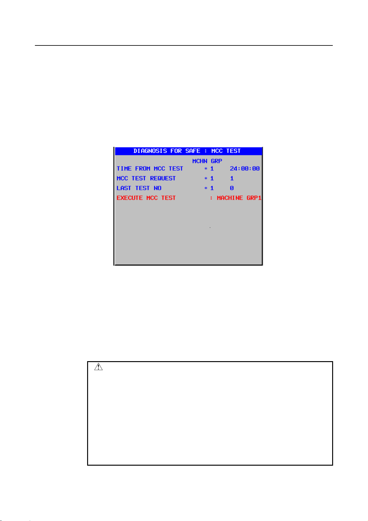
5.I/O SIGNALS B-64483EN-2/01
[Function] This signal notifies that MCC off Test mode is required and a check should be made to
determine whether the safety output signals (MCC Off signal (*MCF)) operate normally.
When MCC Off Test Execution Request signal (RQT) is set to 1, set MCC off Test mode
and carry out a safety output signal MCC off Test as soon as possible.
When MCC Off Test Execution Request signal (RQT) is 1, a machine tool builder must
make ladder not to release a guard lock.
Once a guard is closed when MCC Off Test Execution Request signal (RQT) is set to “1”
while a guard is open by Guard Open Request signal (ORQ), it is necessary not to release
a guard lock until MCC off Test request signal (RQT) turns to “0”.
When MCC Off Test Execution Request signal (RQT) is 1, the following screen is
displayed and the warning “EXECUTE MCC TEST” is displayed.
MCC Off Test Execution Request signal (RQT) is not output via the DCS PMC.
Make a ladder program to lock a protective door when MCC Off Test Execution Request
signal (RQT) =1.
[Output condition] In the following case, this signal is set to “1”.
• MCC off Test is not completed after power-on (when bit 3(STP) of parameter
No.10500 is 0).
• Twenty-four hours have elapsed since the completion of the last MCC off Test.
In the following case, this signal sets to “0”.
• MCC off Test is completed.
CAUTION
1 Do not turn Test Mode signal (OPT) to “0” during MCC off Test.
2 In case that there are plural machine groups in a machine, carry
out MCC off Test for each machine group independently.
3 If MCC is shared between two or more machine groups, do not
carry out MCC off Test for those machine groups at the same time.
4 If MCC is shared between two or more machine groups and MCC
off Test is carried out in a machine group, VRDY off alarm in
another machine group, which shared MCC, must be ignored by
using all axes of each path VRDY off alarm ignore signal IGNVRY
<Gn066.0> or each axis VRDY off alarm ignore signal IGNVRY1 to
IGNVRY8 <Gn192>.
- 56 -
Page 67

B-64483EN-2/01 5.I/O SIGNALS
WARNING
While the MCC off Test processing is in progress, the MCC Off
signal (*MCF) goes high and low to turn on and off the MCC. Carry
out the MCC off Test in such a state that the turning on or off of the
MCC will not cause a problem.
Safety Brake signal (output)
*BRKx <PMC:Fn754.0 to 7><DCS PMC:F(006+m).0 to 7> (for each axis)
This signal is used to control mechanical brake of each axis.
CNC and SV output Safety Brake signal (*BRKx) to control mechanical brake. When *BRKx is “0”,
mechanical brake is active. When *BRKx is “1”, mechanical brake is not active.
[Classification] Output signal (Dual signal)
[Function] When the Dual Check Safety Function is applied, this signal notifies to activate a
mechanical brake. When MCC is off, a brake should be activated.
[Operation] In emergency stop state or alarm state, a mechanical brake is activated by this signal.
A machine tool builder must connect this signal to a mechanical brake.
[Output condition] In the following case, this signal is “1”.
• Releasing brake state
In the following case, this signal is “0”.
• Activating brake state
The CNC changes the state of this signal even during the brake test. For information
about the control of the brake signal, see the section titled "BRAKE TEST".
CAUTION
During the MCC off Test, the MCC is turned off and on several
times. The brake state of the signal may change depending on the
state of the MCC.
For the control of the brake during the MCC off Test, see "MCC off
Test".
- 57 -
Page 68

5.I/O SIGNALS B-64483EN-2/01
A
(a) In case *BRK signal is “0”
Emergency Stop state (*ESP signal is “0”)
*ESP
*BRK
Servo alarm occurs
larm
*BRK
Power-on
Power
*BRK
(b) In case *BRK signal is “1”
When emergency stop is released (*ESP signal is “1”), MCC can be enabled l
(*MCF signal is “1”). After that, when MCC is turned on, Safety Brake signal
*BRK is turned to “1” after the time specified by the parameter No.1950 is elapsed.
1
0
1
0
1
0
1
0
1
0
1
0
*ESP
*MCF
MCC
*BRK
1
0
1
0
1
0
1
0
Timer for brake signal
NOTE
Periodical maintenance of a brake must be done.
Safety Position Switch signal (output)
SPS1 to SPS32<PMC:Fn755 to Fn758><DCS PMC:F(007+m) to F(010+m)>
This signal shows whether the machine position of a servo axis is within the range specified by the
parameter or not.
[Classification] Output signal (Dual signal)
[Function] This signal notifies that the machine position of the axis specified by the safety parameter
(No.13880 to No.13911) is within the range specified by the safety parameter (No.13920
to No.13951, No.13960 to No.13991). In case of single path system, up to 32 points can
be used.
- 58 -
Page 69

B-64483EN-2/01 5.I/O SIGNALS
In case of 2 or more path system, another 32 points in 2 path area can be used. Then up to
64 points can be used at maximum. This signal notifies that the machine position of the
axis specified by the safety parameter (No.10501 to No.10532) is within the range
specified by the safety parameter (No.10533 to No.10564, No.10565 to No.10596).
NOTE
In a system with 3 or more paths, it is also possible to specify the
path to which the Safety Position Switch signal is to be output, by
using a parameter. For the Safety Position Switch signal, 16 points
can be set for an output signal (F area) per group, and up to 4
groups can be set. Two areas can be assigned to one path.
[Output condition] In the following case, this signal is set to “1”.
• The machine position of the axis is within the specified range.
In the following case, this signal is set to “0”.
• The machine position of the axis is out of the specified range.
[Note] When the axis is just on the boundary of the range (machine position is equal to
parameter setting value), it is regarded that the machine position is within the range.
If the state of two Safety Position Switch of the signal of DCS PMC side and the signal of
PMC side is different more than the specified period, each CPU shuts off MCC by DCS
alarm (PW0010, PW0011).
NOTE
The Safety Position Switch signal starts to work when the reference
position of the target axis is established after the power is turned
on. Until then, "0" is output. The state of position switch is kept to
“0” till then.
Once activating, position is always checked and state of signal is
changed according to the result of checking. Even if the reference
point is lost, the state of signal is changed according to the
coordinate kept in both CNC and servo CPU. So if the special
procedure is required when the reference point is lost, design the
ladder program by combining with Position Information Effect signal
(POSEx).
Safety Speed/Safety Position Selection signal A
SVAx <PMC:Gn752.0 to 7> <DCS PMC:G(004+m).0 to 7> (for each axis)
SPAs <PMC:Gn754.0 to 3> <DCS PMC:G(006+m).0 to 3> (for each spindle)
Safety speed/safety position selection signal B
SVBx <PMC:Gn753.0 to 7> <DCS PMC:G(005+m).0 to 7> (for each axis)
SPBs <PMC:Gn754.4 to 7> <DCS PMC:G(006+m).4 to 7> (for each spindle)
[Classification] Input signal (Dual signal)
[Function] When the Dual Check Safety Function is activated, it is possible to select safety limit
speed and safety machine position of each axis.
This signal is prepared for each axis and each spindle. The final number in the signal
name shows the number of the controlled axis and spindle.
- 59 -
Page 70

5.I/O SIGNALS B-64483EN-2/01
SVAx, SVBx
1: Select safety speed/safety machine position of the 1st axis
x
2: Select safety speed/safety machine position of the 2nd axis
3: Select safety speed/safety machine position of the 3rd axis
: :
: :
, SPBy
SPAy
1: Select safety speed of the 1st spindle
y
2: Select safety speed of the 2nd spindle
: :
: :
[Operation] According to the combination of Safety Speed/Safety Machine Position Selection signal,
safety speed and safety machine position are selected as the following table.
Safety Speed/
Safety Machine Position
Selection signal
SVAn SVBn
SPAn SPBn
0 0
1 0
0 1
1 1
Safety limit speed Safety machine position
Parameter for
servo axis
Safety limit speed 1 Safety machine position 1
No.13821 No.4372 No.13831 No.13832
Safety limit speed 2 Safety machine position 2
No.13822 No.4438 No.13833 No.13834
Safety limit speed 3 Safety machine position 3
No.13823 No.4440 No.13835 No.13836
Safety limit speed 4 Safety machine position 4
No.13824 No.4442 No.13837 No.13838
Parameter
for spindle
+ direction
parameter
- direction
parameter
CAUTION
Safety Speed/Safety Machine Position Selection signal is a safety
signal. This signal is input through both PMC and DCS PMC. Both
CNC and PMC check doubly inconsistency of this signal.
Position Information Effect signal
POSEx <PMC: Fn766.0 to 7><DCS PMC: F(018+m).0 to 7> (for each axis)
This signal is output when Dual Check Safety function is activated and the reference point is established.
When the reference point is not established, the machine system is in danger state because Safety
Machine Position Monitoring and Safety Position Error Monitoring are not active. If this signal is “0”,
Machine Tool Builder has to control not to open the protective door.
[Classification] Output signal (This signal output to both PMC but is not monitored in redundant mode)
[Function] This signal informs whether the reference point is established or not.
0: The reference point is not established.
1: The reference point is established.
[Operation] Each CPU informs whether the reference point is established or not.
In the following case, this signal is turned to “1”.
• After the reference point is established.
• When the follow up operation of absolute pulse coder is finished after power-on
In the following case, this signal is turned to “0”.
• When the reference point is lost
- 60 -
Page 71

B-64483EN-2/01 5.I/O SIGNALS
:
:
NOTE
In case that the reference point is re-established, this signal is
turned to “0” till the reference point is re-established from the
dog-signal is turned off.
Programmable Safety I/O signals
[Classification] Input/Output signal (Dual signal)
[Function] The 8 bytes (64 bit) programmable safe I/Os can be freely defined as the different address
from the above basic safe signals. Each byte of 8 byte programmable safe I/Os can be
assigned on either address of X/Y/R/D or K by parameter. Each byte of the
programmable safe I/O between the PMC and DCS PMC is cross-checked by the CNC
and PMC.
CNC CPU(DCS PMC)
PMC CPU(PMC)
Input Signal 1
Input Signal 2
Input Signal 8
Output Signal 1
Output Signal 2
:
Output Signal 8
I/O Link#3,
I/O Link i,
or
PROFIBUS-DP
CNC and PMC
monitor each
signal.
Input Signal 1
Input Signal 2
Input Signal 8
Output Signal 1
Output Signal 2
:
Output Signal 8
I/O Link#1/#2
or
I/O Link i
[Operation] The combinations of cross-checking these signals are defined by using Safety parameters
as follows.
Signal type Combination No. CNC (DCS PMC) PMC (PMC)
Input
1 No. 11950 No. 11970
2 No. 11951 No. 11971
3 No. 11952 No. 11972
4 No.11953 No.11973
5 No.11954 No.11974
6 No.11955 No.11975
7 No.11956 No.11976
8 No.11957 No.11977
- 61 -
Page 72

5.I/O SIGNALS B-64483EN-2/01
Signal type Combination No. CNC (DCS PMC) PMC (PMC)
Output
1 No.11960 No.11980
2 No.11961 No.11981
3 No.11962 No.11982
4 No.11963 No.11983
5 No.11964 No.11984
6 No.11965 No.11985
7 No.11966 No.11986
8 No.11967 No.11987
Brake Test Start signal
STBT <PMC:Gn193.2> (for each machine group)
[Classification] Input signal (Single signal)
[Function] This input signal is used to start or interrupt a brake test.
Changing the state of this signal from "0" to "1" starts the brake test. When the brake test
is completed successfully, the Brake Test Execution Request signal RQBT is set to "0",
causing the state of this signal to change from "1" to "0" as well.
Changing the state of this signal from "1" to "0" during the brake test causes the test to be
interrupted. The test sequence being executed when the signal is set to "0" is suspended,
and the amount of travel occurring during the brake test, brake signals, and torque limit
are reset. To execute the brake test again, set this signal to "1". The brake test will resume
from the beginning.
Brake Test Execution Request signal
RQBT <PMC:Fn191.3> (for each machine group)
[Classification] Output signal (Single signal)
[Function] This signal is used to request a brake test. If the signal is set to "1", a brake test is
executed. Even if this request signal is set to "1", the operation is allowed to continue
until the current stage of machining is completed. To ensure safety, however, when the
current stage of machining is completed, be sure to start a brake test by setting the Brake
Test Start signal STBT to "1".
When the brake test is executed and completed successfully, this signal is set to "0".
5.4 PROGRAMMABLE SAFETY I/O SIGNAL
The Programmable Safety I/O signal is a safety signal that can be defined by the machine tool builder.
The Dual Check Safety function performs dual monitoring on the system-defined safety signals and the
Programmable Safety I/O signals defined by the machine tool builder. To define the Programmable
Safety I/O signals, use the relevant parameters.
Turning off the Programmable Safety I/O output signal
When the state of *DCALM, *MCF, *MCFPs, or *MCFVx is found to be "0", turn off the Programmable
Safety I/O output signal as necessary.
(a) In case MCC off Test is carried out,
When RQT=1 and OPT=1, ignore *MCF=0.
(b) In case of emergency stop (*ESP=0)
When *ESP=0, ignore *MCF=0.
- 62 -
Page 73

B-64483EN-2/01 5.I/O SIGNALS
5.5 NOTE ON MULTI PATH CONTROL
This section describes cautions about safe-related I/O signals that should be taken in multi-path control.
5.5.1 Machine Group And Multi Path Control
CNC can treat servo axes and spindles by dividing into two classes of groups, machine group and path
In case that a machine has plural machine parts that are controlled independently, machine group is
provided to control a part of machine in such machine. Emergency stop is prepared for each machine
group. The signals for MCC off Test and protective door open/close sequence are provided for each
machine group.
In case that a work piece is machined by plural cutters and plural programs at the same time, multi path
control is applied. An alarm is checked by each path. If servo alarm occurs in a path, MCC of all axes in
the path is shut off.
In case of the alarm by safety check function, MCC of all axes in the path are shut off. Then the safety
area should be set for each path basically.
When plural safety areas are defined in a path, MCC may be shut off by an alarm that occurs in another
safety area. When the safety area is composed by the axes that change assignment to a path, MCC of
other axes are not always shut off. So wire the MCC of all paths, which include the axes changed
assignment to the path, to shut off at the same time.
The safety signals that are cross-checked are provided both on PMC and DCS PMC for each path. The
state must be controlled to be equal.
CAUTION
When “Composite control” or “Path speed control of Multi path control” is
specified, it is possible to give a command to control a servo axis or a spindle in
another path. But in this case, the correspondence between a path and a
belonging servo axis or spindle is not changed. An alarm related to a servo axis
or a spindle occurs in the path that the axis and the spindle originally belong to,
and MCC shut off signal correspond to the axis or spindle is output also in
original path.
Then, as the path that gives a command and the path that an axis and a spindle
belongs to should be regarded as the same group, it is necessary to wire MCC
off signal (*MCFVx, *MCFPs) to shut off the MCC of both path at the same time
when “Composite control” or “Path speed control of Multi path control” is
specified.
- 63 -
Page 74

6.PARAMETERS B-64483EN-2/01
6 PARAMETERS
6.1 OVERVIEW
The parameters related to the dual check safety function (safety parameters) are protected by a code (No.
3225) for the safety parameters. The value of a safety parameter cannot be modified unless the same value
as the code for the safety parameters is set as the key (No. 3226) for the safety parameters.
The safety parameters are stored in two locations on the CNC. The CNC, PMC, servo and spindle
software check the matching of the parameters stored at the two locations. If a mismatch is found, an
alarm is issued.
If the setting of a safety parameter is modified, the power must be turned off then back on. The new
setting of the parameter becomes effective after the power is turned back on.
6.2 DATA TYPE
Parameters are classified by data type as follows:
Data type Valid data range Remarks
Bit
Bit machine group
Bit path
Bit axis
Bit spindle
Byte
Byte machine group
Byte path
Byte axis
Byte spindle
Word
Word machine group
Word path
Word axis
Word spindle
2-word
2-word machine group
2-word path
2-word axis
2-word spindle
Real
Real machine group
Real path
Real axis
Real spindle
See the Standard Parameter Setting
NOTE
1 Each of the parameters of the bit, bit machine group, bit path, bit axis, and bit
spindle types consists of 8 bits for one data number (parameters with eight
different meanings).
0 or 1
-128 to 127
0 to 225
-32768 to 32767
0 to 65535
0 to ±999999999
Tables.
Some parameters handle these
types of data as unsigned data.
Some parameters handle these
types of data as unsigned data.
Some parameters handle these
types of data as unsigned data.
- 64 -
Page 75

B-64483EN-2/01 6.PARAMETERS
NOTE
2 The machine group type allows data to be set separately for each machine
group.
3 The path type allows data to be set separately for each path.
4 The axis type allows data to be set separately for each control axis.
5 The spindle type allows data to be set separately for each spindle axis.
6 The valid data range for each data type indicates a general range. The range
varies according to the parameters. For the valid data range of a specific
parameter, see the explanation of the parameter.
6.3 REPRESENTATION OF PARAMETERS
Parameters of the bit type, bit machine group type, bit path type, bit axis type,
and bit spindle type
Parameters other than the bit-type parameters above
NOTE
1 The parameters, which are described here, are related directly to
2 A parameter usable with only one path control type, namely, the
[Example 1]
#7 #6 #5 #4 #3 #2 #1 #0
0000 EIA NCR ISP CTV TVC
Data No. Data (Data #0 to #7 are bit positions.)
1023 Number of the servo axis for each axis
Data No. Data
Dual Check Safety function. As for the other parameters, please
refer to the parameter manual (B-64490EN).
lathe system (T series) or the machining center system (M series),
is indicated using two rows as shown below. When a row is blank,
the parameter is not usable with the corresponding series.
Parameter HTG is a parameter common to the M and T series, but
Parameters RTV and ROC are parameters valid only for the T
series.
1403
#7 #6
RTV
#5 #4 #3 #2 #1 #0
ROC
HTG
HTG
T series
M series
[Example 2]
The following parameter is provided only for the M series.
1411
Cutting feedrate
- 65 -
T series
M series
Page 76

6.PARAMETERS B-64483EN-2/01
NOTE
3 When "to" is inserted between two parameter numbers, there are
parameters with successive numbers between the two starting and
ending parameter numbers, but those intermediate parameter
numbers are omitted for convenience.
4 The lower-case letter "x" or "s" following the name of a bit-type
parameter indicates the following:
- ”
- ”
x” : Bit axis type parameters
s” : Bit spindle type parameters
6.4 STANDARD PARAMETER SETTING TABLES
Overview
This section defines the standard minimum data units and valid data ranges of the CNC parameters of the
real type, real machine group type, real path type, real axis type, and real spindle type. The data type and
unit of data of each parameter conform to the specifications of each function.
Explanation
(A) Length and angle parameters (type 1)
Unit of data Increment system Minimum data unit Valid data range
IS-A 0.01 -999999.99 to +999999.99
mm
deg.
inch
(B) Length and angle parameters (type 2)
Unit of data Increment system Minimum data unit Valid data range
mm
deg.
inch
IS-B 0.001 -999999.999 to +999999.999
IS-C 0.0001 -99999.9999 to +99999.9999
IS-D 0.00001 -9999.99999 to +9999.99999
IS-E 0.000001 -999.999999 to +999.999999
IS-A 0.001 -99999.999 to +99999.999
IS-B 0.0001 -99999.9999 to +99999.9999
IS-C 0.00001 -9999.99999 to +9999.99999
IS-D 0.000001 -999.999999 to +999.999999
IS-E 0.0000001 -99.9999999 to +99.9999999
IS-A 0.01 0.00 to +999999.99
IS-B 0.001 0.000 to +999999.999
IS-C 0.0001 0.0000 to +99999.9999
IS-D 0.00001 0.00000 to +9999.99999
IS-E 0.000001 0.000000 to +999.999999
IS-A 0.001 0.000 to +99999.999
IS-B 0.0001 0.0000 to +99999.9999
IS-C 0.00001 0.00000 to +9999.99999
IS-D 0.000001 0.000000 to +999.999999
IS-E 0.0000001 0.0000000 to +99.9999999
- 66 -
Page 77
B-64483EN-2/01 6.PARAMETERS
(C) Velocity and angular velocity parameters
Unit of data Increment system Minimum data unit Valid data range
IS-A 0.01 0.00 to +999000.00
mm/min
degree/min
inch/min
IS-B 0.001 0.000 to +999000.000
IS-C 0.0001 0.0000 to +99999.9999
IS-D 0.00001 0.00000 to +9999.99999
IS-E 0.000001 0.000000 to +999.999999
IS-A 0.001 0.000 to +96000.000
IS-B 0.0001 0.0000 to +9600.0000
IS-C 0.00001 0.00000 to +4000.00000
IS-D 0.000001 0.000000 to +400.000000
IS-E 0.0000001 0.0000000 to +40.0000000
(D)Acceleration and angular acceleration parameters
Unit of data Increment system Minimum data unit Valid data range
IS-A 0.01 0.00 to +999999.99
mm/sec2
deg./sec
inch/sec2
2
IS-B 0.001 0.000 to +999999.999
IS-C 0.0001 0.0000 to +99999.9999
IS-D 0.00001 0.00000 to +9999.99999
IS-E 0.000001 0.000000 to +999.999999
IS-A 0.001 0.000 to +99999.999
IS-B 0.0001 0.0000 to +99999.9999
IS-C 0.00001 0.00000 to +9999.99999
IS-D 0.000001 0.000000 to +999.999999
IS-E 0.0000001 0.0000000 to +99.9999999
Notes
(1) Values are rounded up or down to the nearest multiples of the minimum data unit.
(2) A valid data range means data input limits, and may differ from values representing actual
performance.
(3) For information on the ranges of commands to the CNC, refer to Appendix, "List of Command
Ranges," in the "OPERATOR’S MANUAL (Common to Lathe System/Machining Center System)"
(B-64484EN).
(4) The setting value of the parameter related with length and angle depends on whether the attribute of
the axis is diameter specification or radius specification. In case safety function, set the parameter
according to the attribute of the axis at power on.
Even if the attribute is changed after power on, changed value is not used by each safety function.
Each safety function refers to the value that is specified at power on. .
6.5 PARAMETERS
0980 Machine group number of each path
NOTE
When this parameter is set, the power must be turned off before
operation is continued.
- 67 -
Page 78

6.PARAMETERS B-64483EN-2/01
[Input type] Parameter input
[Data type] Byte path
[Valid data range] 1 to 3
Set the machine group number which each path belongs.
NOTE
When 0 is set, each path is assumed to belong to machine group 1.
0981 Absolute path number of each axis
NOTE
When this parameter is set, the power must be turned off before
operation is continued.
[Input type] Parameter input
[Data type] Byte axis
[Valid data range] 1 to 10
Set the path to which each axis belongs.
NOTE
When 0 is set, each axis is assumed to belong to path 1.
0982 Absolute path number of each spindle
NOTE
When this parameter is set, the power must be turned off before
operation is continued.
[Input type] Parameter input
[Data type] Byte spindle
[Valid data range] 1 to 10
Set the path to which each spindle belongs.
NOTE
When 0 is set, each spindle is assumed to belong to path 1.
1023 Servo axis number of each axis
NOTE
When this parameter is set, the power must be turned off before
operation is continued.
[Input type] Parameter input
[Data type] Byte axis
[Valid data range] 0 to Number of controlled axis
Set the servo axis for each control axis. Usually set to same number as the control axis
number.
The control axis number is the order number that is used for setting the axis-type
parameters or axis-type machine signals
* With an axis for which Cs contour control/spindle positioning is to be performed, set
-(spindle number) as the servo axis number.
Example) When exercising Cs contour control on the fourth controlled axis by
- 68 -
Page 79

B-64483EN-2/01 6.PARAMETERS
using the first spindle, set -1.
* For tandem controlled axes or electronic gear box (EGB) controlled axes, two axes
need to be specified as one pair. So, make a setting as described below.
Tandem axis: For a master axis, set an odd (1, 3, 5, 7, ...) servo axis number.
For a slave axis to be paired, set a value obtained by adding 1 to the
value set for the master axis.
EGB axis: For a slave axis, set an odd (1, 3, 5, 7, ...) servo axis number. For a
dummy axis to be paired, set a value obtained by adding 1 to the value
set for the slave axis.
1240
Coordinates value of the reference position in the machine coordinate system
NOTE
When this parameter is set, the power must be turned off before
operation is continued.
[Input type] Parameter input
[Data type] Real axis
[Unit of data] mm, inch, degree (machine unit)
[Minimum unit of data] Depend on the increment system of the applied axis
[Valid data range] 9 digit of minimum unit of data (Refer to standard parameter setting table(A). But in case
that CMR≥1, data range becomes 1/CMR of 9 digits of minimum unit of data.)
(When the increment system is IS-B and CMR=1, -999999.999 to +999999.999)
(When the increment system is IS-B and CMR=2, -499999.999 to +499999.999)
NOTE
Whether to specify this parameter by using a diameter value or
radius value depends on whether the corresponding axis is based
on diameter specification or radius specification.
Set the coordinate values of the reference position in the machine coordinate system.
1838 Position deviation limit for each axis in moving state during safety check
NOTE
When this parameter is set, the power must be turned off before
operation is continued.
[Input type] Parameter input
[Data type] 2-word axis
[Unit of data] Detection unit
[Valid data range] 0 to 99999999
Position deviation limit for each axis in moving state for safety check of Dual Check
Safety function is specified.
If position deviation of a moving axis exceeds position deviation limit while Safety
Check is carried out (Safety Monitoring Request *VLDVx =“0”), a servo alarm (SV0475,
SV1071) is generated and axes are stopped immediately like emergency stop state.
In Dual Check Safety function, position deviation is always checked by CNC and Servo.
In case that Safety Check is carried out (Safety Monitoring Request *VLDVx =“0”), the
servo alarm (SV0475,SV1071) is generated when each CPU finds out that the deviation
exceeds position deviation limit in moving state.
- 69 -
Page 80

6.PARAMETERS B-64483EN-2/01
1839 Position deviation limit for each axis in stopped state during safety check
NOTE
When this parameter is set, the power must be turned off before
operation is continued.
[Input type] Parameter input
[Data type] 2-word axis
[Unit of data] Detection unit
[Valid data range] 0 to 99999999
Set the positioning deviation limit in stopped state for each axis for Dual Check Safety
function.
If the positioning deviation exceeds the positioning deviation limit during stopped state
while Safety Check is carried out (Safety Monitoring Request *VLDVx =“0”), a servo
alarm (SV0474, SV1072) is generated, and operation is stopped immediately (as in
emergency stop).
In Dual Check Safety function, position deviation is always checked by CNC and Servo.
In case that Safety Check is carried out (Safety Monitoring Request *VLDVx =“0”),
servo alarm (SV0474,SV1072) is generated when each CPU finds out that the deviation
exceeds position deviation limit in stopped state.
1840 Position deviation limit for each axis in servo-off state during safety check
NOTE
When this parameter is set, the power must be turned off before
operation is continued.
[Input type] Parameter input
[Data type] 2-word axis
[Unit of data] Detection unit
[Valid data range] 0 to 99999999
Set the positioning deviation limit in servo-off state for each axis for Dual Check Safety
function.
If the positioning deviation exceeds the positioning deviation limit during servo-off, a
servo alarm (SV1069,SV1070) is generated, and operation is stopped immediately (as in
emergency stop).
In Dual Check Safety function, position deviation is always checked by CNC and Servo.
Servo alarm (SV1069,SV1070) is generated when each CPU finds out that the deviation
exceeds position deviation limit in servo-off state.
1841
Position deviation limit of each axis in moving state during other than Safety Check is carried out
NOTE
When this parameter is set, the power must be turned off before
operation is continued.
[Input type] Parameter input
[Data type] 2-word axis
[Unit of data] Detection unit
[Valid data range] 0 to 99999999
Set the positioning deviation limit in moving state for each axis for Dual Check Safety
function, in case that Safety Check is not carried out (Safety Monitoring Request
*VLDVx=“1”).
- 70 -
Page 81

B-64483EN-2/01 6.PARAMETERS
In case that Safety Check is not carried out (Safety Monitoring Request *VLDVx =“1”),
servo alarm (SV0475,SV1071) is generated and operation is stopped immediately (as in
emergency stop), when each CPU finds out that the deviation exceeds position deviation
limit in moving state.
If the value of this parameter is “0”, the parameter No.1828 is used for the value of
deviation limit in moving state.
In case that Safety Check is carried out (Safety Monitoring Request “*VLDVx” =0), the
parameter No.1838 is used for the value of deviation limit in moving state.
1842
Position deviation limit of each axis in stopped state during other than Safety Check is carried out
NOTE
When this parameter is set, the power must be turned off before
operation is continued.
[Input type] Parameter input
[Data type] 2-word axis
[Unit of data] Detection unit
[Valid data range] 0 to 99999999
Set the positioning deviation limit in stopped state for each axis for Dual Check Safety
function, in case that Safety Check is not carried out (Safety Monitoring Request
*VLDVx=“1”).
In case that Safety Check is not carried out (Safety Monitoring Request *VLDVx =“1”),
servo alarm (SV0474,SV1072) is generated and operation is stopped immediately (as in
emergency stop), when each CPU finds out that the deviation exceeds position deviation
limit in stopped state.
If the value of this parameter is “0”, the parameter No.1829 is used for the value of
deviation limit in stopped state.
In case that Safety Check is carried out (Safety Monitoring Request *VLDVx =“0”), the
parameter No.1839 is used for the value of deviation limit in stopped state.
#7 #6 #5 #4 #3 #2 #1 #0
1902 DCE
NOTE
When this parameter is set, the power must be turned off before
operation is continued.
[Input type] Parameter input
[Data type] Bit
#6 DCE Dual Check Safety function is
0: inactive.
1: active.
This parameter invalidates Dual Check Safety function temporarily.
In the system with Dual Check Safety function, this parameter is used when the system
set up without wiring and ladder related with Dual Check Safety in order to set up other
function.
- 71 -
Page 82

6.PARAMETERS B-64483EN-2/01
NOTE
1 When Dual Check Safety function is used, this parameter must be
set to “1”. If Dual Check Safety function is ordered and this
parameter is “0”, an alarm (DS0022) is displayed at power-on. This
alarm can be reset by pushing “CAN” and “RESET” key on MDI at
the same time.
2 When the Dual Check Safety function is disabled, almost
safety-related functions become disabled. Only the following
functions become enabled when the Dual Check Safety function is
disabled.
MCC Off signal *MCF (for each machine group)
•
The state of MCC Off signal *MCF on the PMC and DCSPMC
sides changes depending on the state of the emergency stop
signal on the PMC side (the state of the emergency stop signal
on the DCSPMC side has no effect). The MCC off Test is
disabled.
Brake signal *BRKx (for each axis)
•
Brake signal *BRKx operates only on the PMC side. Note that
the signal on the DCSPMC side always indicates the brake
release state. The output signals other than the above are
described below.
(1) The following signals always indicate "1" on both the PMC and
DCSPMC sides.
- MCC Off signal *DCALM (one for each system)
- MCC Off signals *MCFVx (for each axis) and *MCFPs (for
each spindle)
- Safety monitoring result signals RSVx (for each axis) and
RSPs (for each spindle)
(2) The following signals always indicate "0" on both the PMC and
DCSPMC sides.
- Safe Position Switch signals SPS1 to SPS32
- Guard Open Inhibit signal *OPIHB
- MCC Off Test Execution Request signal RQT
- Position Information Effect signal POSEx
#7 #6 #5 #4 #3 #2 #1 #0
1904 DCN
NOTE
When this parameter is set, the power must be turned off before
operation is continued.
[Input type] Parameter input
[Data type] Bit axis
#6 DCN The checks of the target axis by Dual Check Safety function are:
0: carried out.
1: not carried out.
- 72 -
Page 83

B-64483EN-2/01 6.PARAMETERS
NOTE
1 It is not possible to inhibit each check of Dual Check Safety
Function of all axes by the parameter DCN.
2 Set the DCN bit to 1 for the dummy axis under tandem control or
for the tool axis of a electronic gear box or electronic gear box
2-pair.
3 The checks by the dual check safety function are not carried out on
an axis for which the DCN bit is set to 1. Set the DCN bit to 0 for
normal axes.
1945 Safety-related I/O check timer
NOTE
When this parameter is set, the power must be turned off before
operation is continued.
[Input type] Parameter input
[Data type] Word machine group
[Unit of data] msec
[Valid data range] 0 to 1000
There are two paths for the safety-related I/O signals (those duplicated by the Dual Check
Safety function): one on the PMC side and the other on the DCS PMC side. The CNC
CPU and the PMC CPU constantly exchange their I/O signals with each other and
monitor each other. If a mismatch between double input/output signals through two paths
lasts greater than the time set in this parameter, alarm PW0010, PW0011, PW0012 or
PW0013 is generated.
If a value of less than 16 is specified, it is assumed that 16 ms is specified.
If a value of more than 1000 is specified, it is assumed that 1000 ms is specified.
NOTE
The same value is applied to each path that belongs to a machine
group.
1946 MCC off Test timer
NOTE
When this parameter is set, the power must be turned off before
operation is continued.
[Input type] Parameter input
[Data type] Word machine group
[Unit of data] msec
[Valid data range] 0 to 32767
When MCC off Test mode is selected with Dual Check Safety function, CNC CPU
carries out MCC off Test by the safety output signal (*MCF). If MCC off Test is not
completed within the time set in this parameter, a servo alarm SV0488 is generated.
If a value of less than 0 is specified, it is assumed that 10000 ms is specified.
NOTE
The same value is applied to each path that belongs to a machine
group.
- 73 -
Page 84

6.PARAMETERS B-64483EN-2/01
1948 MCC off timer
NOTE
When this parameter is set, the power must be turned off before
operation is continued.
[Input type] Parameter input
[Data type] Word machine group
[Unit of data] msec
[Valid data range] 0 to 32767
• CNC CPU and PMC CPU set MCC Off signal (*MCFVx) to 0, when an axis is not
stopped within the time set by this parameter after Safe Speed Monitoring or Safe
Machine Position Monitoring function of Dual Check Safety function detects
abnormal condition.
• When there is no spindle (spindle for which *VLDPs = 1 is set) not being monitored
for its safety in the machine group, MCC Off signal *MCF (for each machine group)
is set to "0" upon elapse of the time set in this parameter after an emergency stop is
made.
• When a crosscheck alarm or CPU self diagnosis alarm occurs, MCC Off signal
*DCALM (one for each system) is set to "0" upon elapse of the time set in this
parameter. If a crosscheck alarm or CPU self diagnosis alarm related to the spindle
occurs, however, the time set in this parameter takes no effect.
NOTE
The same value is applied for each path that belongs to a machine
group.
1950 Brake signal timer
NOTE
When this parameter is set, the power must be turned off before
operation is continued.
[Input type] Parameter input
[Data type] Word machine group
[Unit of data] msec
[Valid data range] 0 to 32767
Set a time period from when CNC CPU and Servo CPU in Dual Check Safety function
detects that the servo amplifier is ready (MCC on state) until Safety Brake signal
(*BRKx) goes 1 (brake release enabled).
NOTE
The same value is applied for each path that belongs to a machine
group.
3021 Address to which an axis signal is assigned
NOTE
When this parameter is set, the power must be turned off before
operation is continued.
[Input type] Parameter input
- 74 -
Page 85

B-64483EN-2/01 6.PARAMETERS
[Data type] Byte axis
[Valid data range] 0 to 7, 10 to 17, 20 to 27, ... , 90 to 97
For each axis of the CNC, set a PMC interface address.
Set a value according to the tables below.
Value of parameter No. 3021 (the second digit)
Setting value Input signal address Output signal address
0 G0000 to G0767 F0000 to F0767
1 G1000 to G1767 F1000 to F1767
⋅ ⋅ ⋅
9 G9000 to G9767 F9000 to F9767
Value of parameter No. 3021 (the first digit)
Setting value Input signal address Output signal address
0 #0 #0
1 #1 #1
⋅ ⋅ ⋅
7 #7 #7
[Example of setting]
Axis number No.3021 Signal allocation
1 0 +J1<G0100.0>, -J1<G0102.0>, ZP1<F0090.0>, ...
2 1 +J2<G0100.1>, -J2<G0102.1>, ZP2<F0090.1>, ...
3 2 +J3<G0100.2>, -J3<G0102.2>, ZP3<F0090.2>, ...
4 10 +J4<G1100.0>, -J4<G1102.0>, ZP4<F1090.0>, ...
5 11 +J5<G1100.1>, -J5<G1102.1>, ZP5<F1090.1>, ...
If eight or less axes are used per path, the following signal allocation results when 0 is set
for all axes:
Axis 1 of path 1 = Setting equivalent to 0
Axis 2 of path 1 = Setting equivalent to 1
:
Axis 1 of path 2 = Setting equivalent to 10
:
NOTE
Set this parameter when more than eight axes are used per path.
The valid data range varies, depending on the system software.
3022 Address to which a spindle signal is assigned
NOTE
When this parameter is set, the power must be turned off before
operation is continued.
[Input type] Parameter input
[Data type] Byte spindle
[Valid data range] 0to3,10to13,20to23, ... ,90to93
For each axis of the CNC, set a PMC interface address.
Set a value according to the tables below.
- 75 -
Page 86

6.PARAMETERS B-64483EN-2/01
Value of parameter No. 3022 (the second digit)
Setting value Input signal address Output signal address
0 G0000 to G0767 F0000 to F0767
1 G1000 to G1767 F1000 to F1767
⋅ ⋅ ⋅
9 G9000 to G9767 F9000 to F9767
Value of parameter No. 3022 (the first digit)
Setting value Input signal address Output signal address
0 Bit position A Bit position A
1 Bit position B Bit position B
2 Bit position C Bit position C
3 Bit position D Bit position D
(The bit positions A, B, C and D vary, depending on the type of signal.)
[Example of setting]
Spindle number No.3022 Sign al allo catio n
1 0 TLMLA<G0070.0>, TLMHA<G0070.1>, ALMA<F0045.0>, ...
2 1 TLMLB<G0074.0>, TLMHB<G0074.1>, ALMB<F0049.0>, ...
3 10 TLMLA<G1070.0>, TLMHA<G1070.1>, ALMA<F1045.0>, ...
4 11 TLMLB<G1074.0>, TLMHB<G1074.1>, ALMB<F1049.0>, ...
If four or less axes are used per path, the following signal allocation results when 0 is set
for all axes:
Axis 1 of path 1 = Setting equivalent to 0
Axis 2 of path 1 = Setting equivalent to 1
:
Axis 1 of path 2 = Setting equivalent to 10
NOTE
Set this parameter when more than four axes are used per path.
The valid data range varies, depending on the system software.
3225 Code for safety parameters
NOTE
When this parameter is set, the power must be turned off before
operation is continued.
[Input type] Parameter input
[Data type] 2-word
[Valid data range] 0 to 99999999
Set a code (password) for protecting against modifications to parameters related to Dual
Check Safety function (safety parameters). When a code for safety parameters is set other
than the value “0”, the parameters are locked. In this state, the setting (code) is not
displayed but is blank, and safety parameter input is disabled.
If an attempt is made to input data in a locked safety parameter, the result indicated in the
table below is produced, depending on the method of input. No attempt is successful.
Input method Result
MDI input Warning “WRITE PROTECT”
Input via reader/puncher interface No alarm is generated. But parameter input is disabled.
Input through window function Completion code 7 (WRITE PROTECT)
- 76 -
Page 87

B-64483EN-2/01 6.PARAMETERS
If the value other than “0” is set to this parameter, the safety parameter is not displayed.
The safety parameters can be set when the safety parameters are not locked, that is, when
the code for safety parameters is 0, or when the code for safety parameters is the same as
the key for safety parameters (No. 3226).
The following safety parameters are protected by a code for safety parameters:
No.980, No.981, No.982, No.1023, No.1240, No.1838, No.1839, No.1840, No.1841,
No.1842,No.1902#6, No1904, No.1945, No.1946, No.1948, No.1950, No.2000, No.2023,
No.2024, No.2084, No.2085, No.2185, No.3021, No.3022, No.3225, No.3717, No.3797,
No.4372, No.4438, No.4440, No.4442, No.4448, No.4545, No.10500, No.10501-
No.10596, No.11950-No.11957, No.11960-No.11967, No.11970-No.11977, No.11980-
No.11987, No.13806, No.13811, No.13821-No.13829, No.13831-No.13838, No.13840-
No.13843, No.13880-No.13911, No.13912-No.13919, No.13920-No.13951, No.13960-
No.13991
NOTE
Once parameters are locked, the lock must be released or memory
must be cleared before the safety parameters can be modified.
Moreover, the code for the safety parameters cannot be modified in
locked condition. Be careful when setting a code for safety
parameters.
3226 Key for safety parameters
NOTE
When this parameter is set, the power must be turned off before
operation is continued.
[Input type] Parameter input
[Data type] 2-word
[Valid data range] 0 to 99999999
When the same value as the code for safety parameters No.3225 is set in this parameter,
the key is opened to enable modifications to the safety parameters. The value set in this
parameter is not displayed.
When the value other than 0 is set to the code for safety parameters No.3225 and the
value is different from this parameter, the key is locked and the safety parameters can not
be modified.
When the power is turned off, the value set in this parameter is cleared to 0. Then the
power-off results in the locked state.
3717 Motor number to each spindle
NOTE
When this parameter is set, the power must be turned off before
operation is continued.
[Input type] Parameter input
[Data type] Byte spindle
[Valid data range] 0 to Maximum number of controlled spindle axes
Set a spindle amplifier number to be assigned to each spindle.
0: No spindle amplifier is connected.
1: Spindle motor connected to amplifier number 1 is used.
2: Spindle motor connected to amplifier number 2 is used.
- 77 -
Page 88

6.PARAMETERS B-64483EN-2/01
to
n: Spindle motor connected to amplifier number n is used.
#7 #6 #5 #4 #3 #2 #1 #0
3797 DCN
NOTE
When this parameter is set, the power must be turned off before
operation is continued.
[Input type] Parameter input
[Data type] Bit spindle
#0 DCN Each safety check of Dual Check Safety function for the specified spindle is
0: carried out.
1: not carried out.
Set “1” to this bit for the spindle that is not required to apply Dual Check Safety.
4372 Safe speed 1 for each spindle
4438 Safe speed 2 for each spindle
4440 Safe speed 3 for each spindle
4442 Safe speed 4 for each spindle
NOTE
When these parameters are set, the power must be turned off
before operation is continued.
[Input type] Parameter input
[Data type] Word spindle
[Unit of data] min
[Valid data range] 0 to 32767
#7 #6 #5 #4 #3 #2 #1 #0
4399 CTLSTP
[Input type] Parameter input
[Data type] Bit spindle
#1 CTLSTP When the safe speed over alarm is detected:
-1
Set a safe speed for each spindle in terms of motor speed. In case Dual Check Safety
function is activated, CNC and Spindle always check the speed of each spindle motor.
When it is detected that revolution speed of spindle exceeds safety speed limit,
Monitoring Result signal (RSPs) is set to “0”. Moreover if the safety check is carried out
(Safety Check Request signal *VLDPs =”0”), an alarm SP0757(CNC side) or
SP9069(Spindle side) occurs.
Safety Speed can be set up to 4 data. Which speed should be selected is decided by Safety
Speed Selection signal (SPAs/SPBs). Please refer more detail to the description about
Safety Speed/Safety Position Selection signal.
0: Performs a free running stop.
1: Performs a controlled stop. (When the motor speed is reduced to the zero-speed
detection signal (SST) level or less, excitation is turned off.)
- 78 -
Page 89

B-64483EN-2/01 6.PARAMETERS
4448 Stop check level
NOTE
When this parameter is set, the power must be turned off before
operation is continued.
[Input type] Parameter input
[Data type] Word spindle
[Unit of data] min
-1
[Valid data range] 0 to 32767
When the speed of the spindle motor is reduced to the speed specified by this parameter
or less during free running or controlled stop operation due to the safe speed over alarm,
the motor is assumed to have stopped. The setting value must be lower than the parameter
“Safe Speed for each spindle”.
#7 #6 #5 #4 #3 #2 #1 #0
10500 STP APM AVM
NOTE
When at least one of these parameters is set, the power must be
turned off before operation is continued.
[Input type] Parameter input
[Data type] Bit path
#0 AVM In case that a servo alarm occurs,
0: MCC off signal (*MCFVx) is turned to “0” when some servo alarm occurs.
1: MCC off signal (*MCFVx) is turned to “0” when any servo alarm occurs.
In case that this parameter is set to “1”, MCC off signal (*MCFVx) of all axes, which
belong to the same path as the alarm axis, are turned to “0” when a servo alarm occurs.
#1 APM In case that a spindle alarm (SPxxxx) occurs
0: MCC off signal (*MCFPs) is turned to “0” when some spindle alarm occurs.
1: MCC off signal (*MCFPs) is turned to “0” when any spindle alarm occurs.
In case that this parameter is set to “1”, MCC off signal (*MCFPs) of all spindles, which
belong to the same path as the alarm spindle, are turned to “0” when a spindle alarm
occurs.
#3 STP When the power is turned on, a MCC off test is:
0: Carried out. (The screen is changed to Dual Check Safety Diagnosis screen
automatically and the warning "EXECUTE MCC TEST" is displayed at power-on,
and MCC off Test execution request signal (RQT) is output.)
1: Not carried out.
CAUTION
1 The STP parameter is used temporarily, for example, when a MCC
off Test is not to be made at power-on as in the case of machine
adjustment.
2 After adjustment, set STP = 0.
- 79 -
Page 90

6.PARAMETERS B-64483EN-2/01
CAUTION
3 Even when STP = 1, a MCC off Test is required if the power is
turned 24 hours or more after the completion of the previous MCC
off Test.
4 The same value must be set to the path that belongs to the same
machine group.
5 The screen is changed to “ALARM SCREEN” when an alarm
occurs at power-on. In this case, Dual Check Safety Diagnosis
screen is not displayed at power-on automatically.
#7 #6 #5 #4 #3 #2 #1 #0
10597 SDS DPN IDD
[Input type] Parameter input
[Data type] Bit path
#0 IDD On the Dual Check Safety Diagnosis screen, the following information is:
0: Not displayed.
1: Displayed.
• Safety speed limit (unit: mm/min, inch/min, deg/min)
• Safe feed limit/safe machine position selection signal
• Safe feed limit/safe machine position selection signal in case of an alarm
• Programmable Safety I/O signal
NOTE
When using the virtual MDI key function, do not set this parameter to
"1".
#1 DPN The ALARM INFORMATION screen for the cross check by the Dual Check Safety
function displays:
0: CNC-side address
1: PMC-side address and PMC path number
#3 SDS In the CROSS CHECK DATA screen of the Dual Check Safety Diagnosis screen, the
code name of the signal is:
0: Not displayed.
1: Displayed.
13810 Power-on safety-related I/O check start timer
NOTE
When this parameter is set, the power must be turned off before
operation is continued.
[Input type] Parameter input
[Data type] Word
[Unit of data] msec
[Valid data range] 0 to 32767
In Dual Check Safety function, the time from “CNC start-up” to “I/O cross check error
start” is specified just after power-on.
- 80 -
Page 91

B-64483EN-2/01 6.PARAMETERS
A
A
13811 Hysteresis width of position switch (Dual Check Safety)
NOTE
When this parameter is set, the power must be turned off before
operation is continued.
[Input type] Parameter input
[Data type] Real axis
[Unit of data] mm, inch, deg (Machine unit)
[Least unit of data] According to the input increment of corresponding axis
[Valid data range] 0 or positive 9 digit of least input increment of data (Refer to standard parameter setting
table(B). But in case that CMR≥1, data range becomes 1/CMR of 9 digits of least input
increment of data.)
(When the increment system is IS-B and CMR=1, 0 to +999999.999)
(When the increment system is IS-B and CMR=2, 0 to +499999.999)
NOTE
Whether to specify this parameter by using a diameter value or
radius value depends on whether the corresponding axis is based
on diameter specification or radius specification.
Around the position switch boundary for the Dual Check Safety function, the Safety
Position Switch signal may repeatedly turn on and off due to motor vibration. According
to this problem, position switch is inconvenient to use. So “hysteresis” described below is
applied.
Minimum limit of
position switch
Width of hysteresis
Fig.6.5(a) Activated area of the position switch when the Safety Position Switch signal is set to "0"
Minimum limit of
position switch
Fig.6.5(b) Activated area of the position switch when the Safety Position Switch signal is set to "1"
ctivated area of position switch
ctivated area of position switch
Maximum limit of
position switch
Width of hysteresis
Maximum limit o f
position switch
Suppose that the minimum limit and maximum limit of the position switch are
represented by an area like those shown above. If the value of the Safety Position Switch
signal used for the last measurement is "0", then the check is made in an area that takes
into account the width of hysteresis (Fig. 6.5 (a)). If the value of the last used Safety
Position Switch signal is "1", then the check is made in an area that does not take into
account the width of hysteresis (Fig. 6.5 (b)). This reduces the fluctuation in the Safety
Position Switch signal.
- 81 -
Page 92

6.PARAMETERS B-64483EN-2/01
13821 Safety limit speed 1 in position control for each axis
13822 Safety limit speed 2 in position control for each axis
13823 Safety limit speed 3 in position control for each axis
13824 Safety limit speed 4 in position control for each axis
NOTE
When these parameters are set, the power must be turned off
before operation is continued.
[Input type] Parameter input
[Data type] Real axis
[Unit of data] mm/min, inch/min, degree/min (machine unit)
[Minimum unit of data] Depend on the increment system of the applied axis
[Valid data range] Refer to the standard parameter setting table (C)
(When the increment system is IS-B, 0.0 to +240000.0)
Set a safety speed for each axis in position control.
CNC and Servo always check the velocity command of each axis in Dual Check Safety
function. If the speed is exceeded the safety limit even on one axis, Monitoring Result
signal (RSVx) corresponding to that axis is set to “0”. Moreover if Safety Check request
signal (*VLDVx) is set to “0”, an alarm SV0476 or SV0494 is generated for the
corresponding axis.
A safety speed parameter for each axis in feed control is from No.13826 to No.13829.
Up to 4 safety speed can be specified. Safety speed is selected by Safety Speed / Safety
Position Selection signal (SVAx/SVBx). As for the detail of Safety Speed / Safety
Position Selection signal, refer to the description about Safety Speed / Safety Position
Selection signal.
CAUTION
1 The safety speed checks are made on the basis of the speed
converted to the detection unit. Accordingly, a calculation error may
occur.
2 After safety speed parameters No.13821 to No.13824 have been
set, the power must be turned off then back on for the setting to
become effective
3 For diameter specification, set the speed by the diameter (use
changes in diameter/rev or in diameter/min).
13825 Speed regarded as axis stop for Dual Check Safety
NOTE
When this parameter is set, the power must be turned off before
operation is continued.
[Input type] Parameter input
[Data type] Real axis
[Unit of data] mm/min, inch/min, degree/min (machine unit)
[Minimum unit of data] Depend on the increment system of the applied axis
[Valid data range] 0 to 10000
This parameter sets the speed regarded as axis stop in case that an abnormal condition is
found in safety speed check or safety machine position check of Dual Check Safety
function.
- 82 -
Page 93

B-64483EN-2/01 6.PARAMETERS
When an abnormal condition is found in safety speed check or safety machine position
check, a servo alarm occurs. And whether MCC off signal (*MCFVx) is turned off or not
is decided by judging if an axis is stopped after the decided time elapse. At that time, this
parameter gives the speed to judge axis stop.
In case an abnormal condition is detected and an axis is stopped within the given time, an
MCC is not turned off. Then the system can be recovered by reset operation without
power-off.
NOTE
1 For diameter specification, set the speed by the diameter (use
changes in diameter/rev or in diameter/min).
2 In case of velocity control, set the value calculated by the following
-1
formula to this parameter when R(min
) is the velocity, at which the
axis is regarded as stopped.
Setting value = R * PLS * Minimum data unit (Machine unit)
* N / CMR
PLS: Pulse per one revolution of motor (Detection unit)
CMR: Command multiplier
N: In case of diameter specification, N=2.
In other case, N=1.
Minimum data unit: Refer to “STANDARD PARAMETER
SETTING TABLE”.
13826 Safety limit speed 1 in velocity control for each axis
13827 Safety limit speed 2 in velocity control for each axis
13828 Safety limit speed 3 in velocity control for each axis
13829 Safety limit speed 4 in velocity control for each axis
NOTE
When these parameters are set, the power must be turned off
before operation is continued.
[Input type] Parameter input
[Data type] 2-word axis
[Unit of data] min
[Valid data range] 0 to maximum motor speed
13831 Safety machine position 1 for each axis (+ direction)
13832 Safety machine position 1 for each axis (- direction)
13833 Safety machine position 2 for each axis (+ direction)
13834 Safety machine position 2 for each axis (- direction)
13835 Safety machine position 3 for each axis (+ direction)
13836 Safety machine position 3 for each axis (- direction)
13837 Safety machine position 4 for each axis (+ direction)
-1
This parameter sets the safety speed 1 to 4 for each axis in velocity control mode in Dual
Check Safety function.
- 83 -
Page 94

6.PARAMETERS B-64483EN-2/01
13838 Safety machine position 4 for each axis (- direction)
NOTE
When these parameters are set, the power must be turned off
before operation is continued.
[Input type] Parameter input
[Data type] Real axis
[Unit of data] mm, inch, degree (machine unit)
[Minimum unit of data] Depend on the increment system of the applied axis
[Valid data range] 9 digits of minimum unit of data (Refer to standard parameter setting table(A). But in
case that CMR≥1, data range becomes 1/CMR of 9 digits of minimum unit of data.)
(When the increment system is IS-B and CMR=1, -999999.999 to +999999.999)
(When the increment system is IS-B and CMR=2, -499999.999 to +499999.999)
NOTE
Whether to specify this parameter by using a diameter value or
radius value depends on whether the corresponding axis is based
on diameter specification or radius specification.
Set a safe machine position for each axis.
CNC and Servo always check the machine position on each axis in Dual Check Safety
function.
If the machine position is out of the safety machine range even on one axis, Monitoring
Result signal (RSVx) corresponding to that axis is set to “0”. Moreover if Safety Check
request signal (*VLDVx) is set to “0”, an alarm SV0477 or SV0495 is generated for the
corresponding axis.
Up to 4 safety machine position can be specified. Safety machine position is selected by
Safety Speed / Safety Position Selection signal (SVAx/SVBx). As for the detail of Safety
Speed / Safety Position Selection signal, refer to the description about Safety Speed /
Safety Position Selection signal.
CAUTION
The safety machine position checks are made on the basis of the
machine position to the detection unit. Accordingly, a calculation
error may occur.
WARNING
1 CNC and Servo check the machine position of only each axis
whose reference position is established, and not check it of each
axis whose reference position is not established.
2 After safety machine position parameters No.13831 to No.13838
have been set, the power must be turned off then back on for the
setting to become effective.
13840 Address to which safety position switch 1 to 16 are assigned
13841 Address to which safety position switch 17 to 32 are assigned
13842 Address to which safety position switch 33 to 48 are assigned
13843 Address to which safety position switch 49 to 64 are assigned
- 84 -
Page 95

B-64483EN-2/01 6.PARAMETERS
NOTE
When these parameters are set, the power must be turned off
before operation is continued.
[Input type] Parameter input
[Data type] Byte
[Valid data range] 0 to 1, 10 to 11, 20 to 21, ... , 90 to 91
According to this parameter, the address to output 64 points of position switch signals can
be assigned for each 16 points. The assigning addresses are F*755 to F*756 (PMC) /
F(007+m) to F(008+m) (DCS PMC) and F*757 to F*758 (PMC) / F(009+m) to
F(010+m) (DCS PMC) in each path. (*: 0 to 9 [path])
The units of this parameter value specifies which address the signal of each path should
be output to, “F*755 to F*756” (PMC) / “F(007+m) to F(008+m)” (DCS PMC) or
“F*757 to F*758” (PMC) / “F(009+m) to F(010+m)” (DCS PMC).
Setting value Assigned address
0 F*755 to F*756(PMC),
F(007+m) to F(008+m) (DCS PMC)
1 F*757 to F*758(PMC),
F(009+m) to F(010+m) (DCS PMC)
The tens of this parameter value specify which path the signal should be output to.
Setting value Output path
0 Path 1
1 Path 2
...
9 Path 10
The relationship between parameter settings and assigned addresses is shown below.
Setting value Assigned address (PMC) Assigned address (DCS PMC)
00 F0755 - F0756 F007 - F008
01 F0757 - F0758 F009 - F010
10 F1755 - F1756 F027 - F028
11 F1757 - F1758 F029 - F030
20 F2755 - F2756 F047 - F048
21 F2757 - F2758 F049 - F050
30 F3755 - F3756 F067 - F068
31 F3757 - F3758 F069 - F070
40 F4755 - F4756 F087 - F088
41 F4757 - F4758 F089 - F090
50 F5755 - F5756 F107 - F108
51 F5757 - F5758 F109 - F110
60 F6755 - F6756 F127 - F128
61 F6757 - F6758 F129 - F130
70 F7755 - F7756 F147 - F148
71 F7757 - F7758 F149 - F150
80 F8755 - F8756 F167 - F168
81 F8757 - F8758 F169 - F170
90 F9755 - F9756 F187 - F188
91 F9757 - F9758 F189 - F190
- 85 -
Page 96

6.PARAMETERS B-64483EN-2/01
[Example]
Parameter No. Setting value Ou tput address of position switch signal
13840 00 F755-F756 (1st to 16th position switch)(PMC)
F007-F008 (1st to 16th position switch)(DCS PMC)
13841 01 F757-F758 (17th to 32nd position switch) (PMC)
F009-F010 (17th to 32nd position switch)(DCS PMC)
13842 50 F5755-F5756 (33rd to 48th position switch) (PMC)
F107-F108 (33rd to 48th position switch)(DCS PMC)
13843 71 F7757-F7758 (49th to 64th position switch) (PMC)
F149-F150 (49th to 64th position switch)(DCS PMC)
NOTE
1 If all setting values are “0”, the output address is regarded as
follows.
Position switch 1 to 16: F755-F756 (PMC) / F007-F008 (DCS PMC)
Position switch 17 to 32: F757-F758 (PMC) / F009-F010 (DCS
PMC)
Position switch 33 to 48: F1755-F1756 (PMC) / F027-F028 (DCS
PMC)
Position switch 49 to 64: F1757-F1758 (PMC) / F029-F030 (DCS
PMC)
2 Do not assign two or more position switch to the same address.
3 The specifiable range depends on the system software.
13880 Axis corresponding to the 1st safe position switch
13881 Axis corresponding to the 2nd safe position switch
: :
13910 Axis corresponding to the 31st safe position switch
13911 Axis corresponding to the 32nd safe position switch
10501 Axis corresponding to the 33rd safe position switch
10502 Axis corresponding to the 34th safe position switch
: :
10531 Axis corresponding to the 63rd safe position switch
10532 Axis corresponding to the 64th safe position switch
NOTE
When these parameters are set, the power must be turned off
before operation is continued.
[Input type] Parameter input
[Data type] Byte
[Valid data range] 0 to Number of controlled axes
Specify the control axis number corresponding to each of the first to 64th safety position
switches sequentially. If the machine coordinate value of the associated axis is within the
range specified by the parameter, the corresponding Safety Position Switch signal is
output on the PMC side and DCS PMC side.
- 86 -
Page 97

B-64483EN-2/01 6.PARAMETERS
WARNING
1 Set 0 for those position switch numbers that are not to be used.
(The safe position switch signal of that number is not output.)
The safe position switch signal for the axis whose bit 6 (DCN) of
parameter No.1904 is 1 (Dual Check Safety is disabled) is not
output.
2 After safety position switch parameters No.13880 to No.13911,
No.10501 to No.10532 have been set, the power must be turned
off then back on for the setting to become effective.
13920 The maximum limit of the 1st safe position switch
13921 The maximum limit of the 2nd safe position switch
: :
13950 The maximum limit of the 31st safe position switch
13951 The maximum limit of the 32nd safe position switch
10533 The maximum limit of the 33rd safe position switch
10534 The maximum limit of the 34th safe position switch
: :
10563 The maximum limit of the 63rd safe position switch
10564 The maximum limit of the 64th safe position switch
NOTE
When these parameters are set, the power must be turned off
before operation is continued.
[Input type] Parameter input
[Data type] Real
[Unit of data] mm, inch, deg (machine unit)
[Min. unit of data] Depend on the increment system of the reference axis
[Valid data range] 9 digit of minimum unit of data (refer to standard parameter setting table (A)). But in case
that CMR≥1, data range becomes 1/CMR of 9 digits of minimum unit of data.)
(When the increment system is IS-B and CMR=1, -999999.999 to +999999.999)
(When the increment system is IS-B and CMR=2, -499999.999 to +499999.999)
NOTE
Whether to specify this parameter by using a diameter value or
radius value depends on whether the corresponding axis is based
on diameter specification or radius specification.
These parameters set the maximum limit of the 1st through 64th safe position switches.
CAUTION
1 When the machine position is equal to parameter setting value, it is
regarded that the machine position is within the range.
2 When the setting of operation range is “maximum limit < minimum
limit”, the corresponding safe position switch is not output.
3 After safety position switch parameters Nos. 13920 to 13951 and
10533 to 10564 have been set, the power must be turned off then
back on for the setting to become effective.
- 87 -
Page 98

6.PARAMETERS B-64483EN-2/01
13960 The minimum limit of the 1st safe position switch
13961 The minimum limit of the 2nd safe position switch
: :
13990 The minimum limit of the 31st safe position switch
13991 The minimum limit of the 32nd safe position switch
10565 The minimum limit of the 33rd safe position switch
10566 The minimum limit of the 34th safe position switch
: :
10595 The minimum limit of the 63rd safe position switch
10596 The minimum limit of the 64th safe position switch
NOTE
When these parameters are set, the power must be turned off
before operation is continued.
[Input type] Parameter input
[Data type] Real
[Unit of data] mm, inch, deg (machine unit)
[Min. unit of data] Depend on the increment system of the reference axis
[Min. unit of data] Depend on the increment system of the reference axis
[Valid data range] 9 digit of minimum unit of data (refer to standard parameter setting table (A)). But in case
that CMR≥1, data range becomes 1/CMR of 9 digits of minimum unit of data.)
(When the increment system is IS-B and CMR=1, -999999.999 to +999999.999)
(When the increment system is IS-B and CMR=2, -499999.999 to +499999.999)
NOTE
Whether to specify this parameter by using a diameter value or
radius value depends on whether the corresponding axis is based
on diameter specification or radius specification.
These parameters set the minimum limit of the 1st through 64th safe position switches.
CAUTION
1 When the machine position is equal to parameter setting value, it is
regarded that the machine position is within the range.
2 When the setting of operation range is “maximum limit < minimum
limit”, the corresponding safe position switch is not output.
3 After safety position switch parameters Nos. 13960 to 13991 and
10565 to 10596 have been set, the power must be turned off then
back on for the setting to become effective.
13912 Brake test enable/disable
NOTE
When this parameter is set, the power must be turned off before
operation is continued.
[Input type] Parameter input
[Data type] Byte axis
- 88 -
Page 99

B-64483EN-2/01 6.PARAMETERS
[Unit of data] None
[Valid data range] 0,1
Select whether to enable or disable the brake test. Set "0" to disable the test and "1" to
enable it.
13913 Brake test interval
NOTE
When this parameter is set, the power must be turned off before
operation is continued.
[Input type] Parameter input
[Data type] Word machine group
[Unit of data] Hour
[Valid data range] 0 to 168
Set the interval of time between the last brake test and the next one. When the time set in
this parameter has elapsed after the brake test ends, the Brake Test Execution Request
signal RQBT is set to "1". If "0" is set, the interval is assumed to be 8 hours.
13914 Time t1 allowed to elapse after the output of the brake signal until the brake is applied
NOTE
When this parameter is set, the power must be turned off before
operation is continued.
[Input type] Parameter input
[Data type] 2-word axis
[Unit of data] ms
[Valid data range] 0 to 999999999
To control when to output the *BRKx signal and move command during the brake test
for an individual axis, set the time allowed to elapse after the *BRKx signal is controlled
until the brake is applied, as well as the time allowed to elapse after the *BRKx signal is
controlled until the brake is released. If the time for applying the brake differs from the
time for releasing it, set the longer time. If "0" is set, the time is assumed to be 400 ms.
13915 Brake test current limit override value
NOTE
When this parameter is set, the power must be turned off before
operation is continued.
[Input type] Parameter input
[Data type] 2-word axis
[Unit of data] (100/255)%
[Valid data range] 0 to 255
Set the current limit override value for the brake test. The relationship between the value
set in this parameter and the torque limit override value is as follows.
Torque limit override value = (set value/255) × 100 (%)
If "0" is set, 12% is assumed.
- 89 -
Page 100

6.PARAMETERS B-64483EN-2/01
13916 Amount of travel specified for the brake test
NOTE
When this parameter is set, the power must be turned off before
operation is continued.
[Input type] Parameter input
[Data type] Real axis
[Unit of data] mm, inch, degree (machine unit)
[Min. unit of data] Depend on the increment system of the applied axis
[Valid data range] 9 digit of minimum unit of data (refer to standard parameter setting table (A))
(When the increment system is IS-B, -999999.999 to +999999.999)
Set the amount of travel to be specified for each axis at the time of the brake test. If "0" is
set, 1.000 mm is assumed.
CAUTION
If this parameter specifies a value that is smaller than the tolerance
value (No. 13918) for the positional deviation to be checked by the
brake test, the brake test may fail to be executed normally.
NOTE
When the diameter is specified ("1" is set in bit 3(DIAx) of parameter
No. 1006), set the diameter value.
13917 Feedrate specified for the brake test
NOTE
When this parameter is set, the power must be turned off before
operation is continued.
[Input type] Parameter input
[Data type] Real axis
[Unit of data] mm/min, inch/min, degree/min (machine unit)
[Min. unit of data] Depend on the increment system of the applied axis
[Valid data range] Refer to the standard parameter setting table (C)
(When the increment system is IS-B, 0.0 to +240000.0)
Set the feedrate to be specified for each axis at the time of the brake test. If "0" is set, 10
mm/min is assumed.
13918 Tolerance value for the positional deviation amount checked by the brake test
NOTE
When this parameter is set, the power must be turned off before
operation is continued.
[Input type] Parameter input
[Data type] 2-word axis
[Unit of data] Detection unit
[Valid data range] 0 to 999999999
- 90 -
 Loading...