

Page 1

FANUC Series 30+-MODEL B
FANUC Series 31+-MODEL B
FANUC Series 32+-MODEL B
DESCRIPTIONS
B-64482EN/03
Page 2

• No part of this manual may be reproduced in any form.
• All specifications and designs are subject to change without notice.
The products in this manual are controlled based on Japan’s “Foreign Exchange and
Foreign Trade Law”. The export of Series 30i-B, Series 31i-B5 from Japan is subject to an
export license by the government of Japan. Other models in this manual may also be
subject to export controls.
Further, re-export to another country may be subject to the license of the government of
the country from where the product is re-exported. Furthermore, the product may also be
controlled by re-export regulations of the United States government.
Should you wish to export or re-export these products, please contact FANUC for advice.
In this manual we have tried as much as possible to describe all the various matters.
However, we cannot describe all the matters which must not be done, or which cannot be
done, because there are so many possibilities.
Therefore, matters which are not especially described as possible in this manual should be
regarded as ”impossible”.
Page 3

B-64482EN/03 SAFETY PRECAUTIONS
SAFETY PRECAUTIONS
This section describes the safety precautions related to the use of CNC units.
It is essential that these precautions be observed by users to ensure the safe operation of machines
equipped with a CNC unit (all descriptions in this section assume this configuration). Note that some
precautions are related only to specific functions, and thus may not be applicable to certain CNC units.
Users must also observe the safety precautions related to the machine, as described in the relevant manual
supplied by the machine tool builder. Before attempting to operate the machine or create a program to
control the operation of the machine, the operator must become fully familiar with the contents of this
manual and relevant manual supplied by the machine tool builder.
CONTENTS
DEFINITION OF WARNING, CAUTION, AND NOTE.........................................................................s-1
GENERAL WARNINGS AND CAUTIONS ............................................................................................ s-2
WARNINGS AND CAUTIONS RELATED TO PROGRAMMING.......................................................s-3
WARNINGS AND CAUTIONS RELATED TO HANDLING ................................................................s-5
WARNINGS RELATED TO DAILY MAINTENANCE .........................................................................s-7
DEFINITION OF WARNING, CAUTION, AND NOTE
This manual includes safety precautions for protecting the user and preventing damage to the machine.
Precautions are classified into Warning and Caution according to their bearing on safety. Also,
supplementary information is described as a Note. Read the Warning, Caution, and Note thoroughly
before attempting to use the machine.
WARNING
Applied when there is a danger of the user being injured or when there is a
danger of both the user being injured and the equipment being damaged if the
approved procedure is not observed.
CAUTION
Applied when there is a danger of the equipment being damaged, if the
approved procedure is not observed.
NOTE
The Note is used to indicate supplementary information other than Warning and
Caution.
• Read this manual carefully, and store it in a safe place.
s-1
Page 4

SAFETY PRECAUTIONS B-64482EN/03
GENERAL WARNINGS AND CAUTIONS
WARNING
1 Never attempt to machine a workpiece without first checking the operation of the
machine. Before starting a production run, ensure that the machine is operating
correctly by performing a trial run using, for example, the single block, feedrate
override, or machine lock function or by operating the machine with neither a tool
nor workpiece mounted. Failure to confirm the correct operation of the machine
may result in the machine behaving unexpectedly, possibly causing damage to
the workpiece and/or machine itself, or injury to the user.
2 Before operating the machine, thoroughly check the entered data.
Operating the machine with incorrectly specified data may result in the machine
behaving unexpectedly, possibly causing damage to the workpiece and/or
machine itself, or injury to the user.
3 Ensure that the specified feedrate is appropriate for the intended operation.
Generally, for each machine, there is a maximum allowable feedrate.
The appropriate feedrate varies with the intended operation. Refer to the manual
provided with the machine to determine the maximum allowable feedrate.
If a machine is run at other than the correct speed, it may behave unexpectedly,
possibly causing damage to the workpiece and/or machine itself, or injury to the
user.
4 When using a tool compensation function, thoroughly check the direction and
amount of compensation.
Operating the machine with incorrectly specified data may result in the machine
behaving unexpectedly, possibly causing damage to the workpiece and/or
machine itself, or injury to the user.
5 The parameters for the CNC and PMC are factory-set. Usually, there is not need
to change them. When, however, there is not alternative other than to change a
parameter, ensure that you fully understand the function of the parameter before
making any change.
Failure to set a parameter correctly may result in the machine behaving
unexpectedly, possibly causing damage to the workpiece and/or machine itself,
or injury to the user.
6 Immediately after switching on the power, do not touch any of the keys on the
MDI panel until the position display or alarm screen appears on the CNC unit.
Some of the keys on the MDI panel are dedicated to maintenance or other
special operations. Pressing any of these keys may place the CNC unit in other
than its normal state. Starting the machine in this state may cause it to behave
unexpectedly.
7 The Operator’s Manual and Programming Manual supplied with a CNC unit
provide an overall description of the machine's functions, including any optional
functions. Note that the optional functions will vary from one machine model to
another. Therefore, some functions described in the manuals may not actually
be available for a particular model. Check the specification of the machine if in
doubt.
8 Some functions may have been implemented at the request of the machine-tool
builder. When using such functions, refer to the manual supplied by the
machine-tool builder for details of their use and any related cautions.
s-2
Page 5

B-64482EN/03 SAFETY PRECAUTIONS
CAUTION
The liquid-crystal display is manufactured with very precise fabrication
technology. Some pixels may not be turned on or may remain on. This
phenomenon is a common attribute of LCDs and is not a defect.
NOTE
Programs, parameters, and macro variables are stored in nonvolatile memory in
the CNC unit. Usually, they are retained even if the power is turned off.
Such data may be deleted inadvertently, however, or it may prove necessary to
delete all data from nonvolatile memory as part of error recovery.
To guard against the occurrence of the above, and assure quick restoration of
deleted data, backup all vital data, and keep the backup copy in a safe place.
WARNINGS AND CAUTIONS RELATED TO PROGRAMMING
This section covers the major safety precautions related to programming. Before attempting to perform
programming, read the supplied Operator’s Manual carefully such that you are fully familiar with their
contents.
WARNING
1
Coordinate system setting
If a coordinate system is established incorrectly, the machine may behave
unexpectedly as a result of the program issuing an otherwise valid move
command. Such an unexpected operation may damage the tool, the machine
itself, the workpiece, or cause injury to the user.
2
Positioning by nonlinear interpolation
When performing positioning by nonlinear interpolation (positioning by nonlinear
movement between the start and end points), the tool path must be carefully
confirmed before performing programming. Positioning involves rapid traverse. If
the tool collides with the workpiece, it may damage the tool, the machine itself,
the workpiece, or cause injury to the user.
3
Function involving a rotation axis
When programming polar coordinate interpolation or normal-direction
(perpendicular) control, pay careful attention to the speed of the rotation axis.
Incorrect programming may result in the rotation axis speed becoming
excessively high, such that centrifugal force causes the chuck to lose its grip on
the workpiece if the latter is not mounted securely. Such mishap is likely to
damage the tool, the machine itself, the workpiece, or cause injury to the user.
4
Inch/metric conversion
Switching between inch and metric inputs does not convert the measurement
units of data such as the workpiece origin offset, parameter, and current
position. Before starting the machine, therefore, determine which measurement
units are being used. Attempting to perform an operation with invalid data
specified may damage the tool, the machine itself, the workpiece, or cause injury
to the user.
s-3
Page 6

SAFETY PRECAUTIONS B-64482EN/03
WARNING
5
Constant surface speed control
When an axis subject to constant surface speed control approaches the origin of
the workpiece coordinate system, the spindle speed may become excessively
high. Therefore, it is necessary to specify a maximum allowable speed.
Specifying the maximum allowable speed incorrectly may damage the tool, the
machine itself, the workpiece, or cause injury to the user.
6
Stroke check
After switching on the power, perform a manual reference position return as
required. Stroke check is not possible before manual reference position return is
performed. Note that when stroke check is disabled, an alarm is not issued even
if a stroke limit is exceeded, possibly damaging the tool, the machine itself, the
workpiece, or causing injury to the user.
7
Tool post interference check
A tool post interference check is performed based on the tool data specified
during automatic operation. If the tool specification does not match the tool
actually being used, the interference check cannot be made correctly, possibly
damaging the tool or the machine itself, or causing injury to the user. After
switching on the power, or after selecting a tool post manually, always start
automatic operation and specify the tool number of the tool to be used.
8
Absolute/incremental mode
If a program created with absolute values is run in incremental mode, or vice
versa, the machine may behave unexpectedly.
9
Plane selection
If an incorrect plane is specified for circular interpolation, helical interpolation, or
a canned cycle, the machine may behave unexpectedly. Refer to the
descriptions of the respective functions for details.
10
Torque limit skip
Before attempting a torque limit skip, apply the torque limit. If a torque limit skip
is specified without the torque limit actually being applied, a move command will
be executed without performing a skip.
WARNING
11
Programmable mirror image
Note that programmed operations vary considerably when a programmable
mirror image is enabled.
12
Compensation function
If a command based on the machine coordinate system or a reference position
return command is issued in compensation function mode, compensation is
temporarily canceled, resulting in the unexpected behavior of the machine.
Before issuing any of the above commands, therefore, always cancel
compensation function mode.
s-4
Page 7

B-64482EN/03 SAFETY PRECAUTIONS
WARNINGS AND CAUTIONS RELATED TO HANDLING
This section presents safety precautions related to the handling of machine tools. Before attempting to
operate your machine, read the supplied Operator’s Manual carefully, such that you are fully familiar
with their contents.
WARNING
1
Manual operation
When operating the machine manually, determine the current position of the tool
and workpiece, and ensure that the movement axis, direction, and feedrate have
been specified correctly. Incorrect operation of the machine may damage the
tool, the machine itself, the workpiece, or cause injury to the operator.
2
Manual reference position return
After switching on the power, perform manual reference position return as
required.
If the machine is operated without first performing manual reference position
return, it may behave unexpectedly. Stroke check is not possible before manual
reference position return is performed.
An unexpected operation of the machine may damage the tool, the machine
itself, the workpiece, or cause injury to the user.
3
Manual numeric command
When issuing a manual numeric command, determine the current position of the
tool and workpiece, and ensure that the movement axis, direction, and command
have been specified correctly, and that the entered values are valid.
Attempting to operate the machine with an invalid command specified may
damage the tool, the machine itself, the workpiece, or cause injury to the
operator.
4
Manual handle feed
In manual handle feed, rotating the handle with a large scale factor, such as 100,
applied causes the tool and table to move rapidly. Careless handling may
damage the tool and/or machine, or cause injury to the user.
5
Disabled override
If override is disabled (according to the specification in a macro variable) during
threading, rigid tapping, or other tapping, the speed cannot be predicted,
possibly damaging the tool, the machine itself, the workpiece, or causing injury
to the operator.
6
Origin/preset operation
Basically, never attempt an origin/preset operation when the machine is
operating under the control of a program. Otherwise, the machine may behave
unexpectedly, possibly damaging the tool, the machine itself, the tool, or causing
injury to the user.
7
Workpiece coordinate system shift
Manual intervention, machine lock, or mirror imaging may shift the workpiece
coordinate system. Before attempting to operate the machine under the control
of a program, confirm the coordinate system carefully.
If the machine is operated under the control of a program without making
allowances for any shift in the workpiece coordinate system, the machine may
behave unexpectedly, possibly damaging the tool, the machine itself, the
workpiece, or causing injury to the operator.
s-5
Page 8

SAFETY PRECAUTIONS B-64482EN/03
WARNING
8
Software operator's panel and menu switches
Using the software operator's panel and menu switches, in combination with the
MDI panel, it is possible to specify operations not supported by the machine
operator's panel, such as mode change, override value change, and jog feed
commands.
Note, however, that if the MDI panel keys are operated inadvertently, the
machine may behave unexpectedly, possibly damaging the tool, the machine
itself, the workpiece, or causing injury to the user.
9
RESET key
Pressing the RESET key stops the currently running program. As a result, the
servo axes are stopped. However, the RESET key may fail to function for
reasons such as an MDI panel problem. So, when the motors must be stopped,
use the emergency stop button instead of the RESET key to ensure security.
10
Manual intervention
If manual intervention is performed during programmed operation of the
machine, the tool path may vary when the machine is restarted. Before restarting
the machine after manual intervention, therefore, confirm the settings of the
manual absolute switches, parameters, and absolute/incremental command
mode.
11
Feed hold, override, and single block
The feed hold, feedrate override, and single block functions can be disabled
using custom macro system variable #3004. Be careful when operating the
machine in this case.
12
Dry run
Usually, a dry run is used to confirm the operation of the machine. During a dry
run, the machine operates at dry run speed, which differs from the
corresponding programmed feedrate. Note that the dry run speed may
sometimes be higher than the programmed feed rate.
13
Cutter and tool nose radius compensation in MDI mode
Pay careful attention to a tool path specified by a command in MDI mode,
because cutter or tool nose radius compensation is not applied. When a
command is entered from the MDI to interrupt in automatic operation in cutter or
tool nose radius compensation mode, pay particular attention to the tool path
when automatic operation is subsequently resumed. Refer to the descriptions of
the corresponding functions for details.
14
Program editing
If the machine is stopped, after which the machining program is edited
(modification, insertion, or deletion), the machine may behave unexpectedly if
machining is resumed under the control of that program. Basically, do not
modify, insert, or delete commands from a machining program while it is in use.
s-6
Page 9

B-64482EN/03 SAFETY PRECAUTIONS
WARNINGS RELATED TO DAILY MAINTENANCE
WARNING
1
Memory backup battery replacement
When replacing the memory backup batteries, keep the power to the machine
(CNC) turned on, and apply an emergency stop to the machine. Because this
work is performed with the power on and the cabinet open, only those personnel
who have received approved safety and maintenance training may perform this
work.
When replacing the batteries, be careful not to touch the high-voltage circuits
(marked and fitted with an insulating cover).
Touching the uncovered high-voltage circuits presents an extremely dangerous
electric shock hazard.
NOTE
The CNC uses batteries to preserve the contents of its memory, because it must
retain data such as programs, offsets, and parameters even while external
power is not applied.
If the battery voltage drops, a low battery voltage alarm is displayed on the
machine operator's panel or screen.
When a low battery voltage alarm is displayed, replace the batteries within a
week. Otherwise, the contents of the CNC's memory will be lost.
Refer to the Section “Method of replacing battery” in the Operator’s Manual
(Common to Lathe System/Machining Center System) for details of the battery
replacement procedure.
WARNING
2
Absolute pulse coder battery replacement
When replacing the memory backup batteries, keep the power to the machine
(CNC) turned on, and apply an emergency stop to the machine. Because this
work is performed with the power on and the cabinet open, only those personnel
who have received approved safety and maintenance training may perform this
work.
When replacing the batteries, be careful not to touch the high-voltage circuits
(marked
and fitted with an insulating cover).
Touching the uncovered high-voltage circuits presents an extremely dangerous
electric shock hazard.
NOTE
The absolute pulse coder uses batteries to preserve its absolute position.
If the battery voltage drops, a low battery voltage alarm is displayed on the
machine operator's panel or screen.
When a low battery voltage alarm is displayed, replace the batteries within a
week. Otherwise, the absolute position data held by the pulse coder will be lost.
Refer to the FANUC SERVO MOTOR
of the battery replacement procedure.
i
series Maintenance Manual for details
α
s-7
Page 10

SAFETY PRECAUTIONS B-64482EN/03
WARNING
3
Fuse replacement
Before replacing a blown fuse, however, it is necessary to locate and remove the
cause of the blown fuse.
For this reason, only those personnel who have received approved safety and
maintenance training may perform this work.
When replacing a fuse with the cabinet open, be careful not to touch the
high-voltage circuits (marked and fitted with an insulating cover).
Touching an uncovered high-voltage circuit presents an extremely dangerous
electric shock hazard.
s-8
Page 11

B-64482EN/03 TABLE OF CONTENTS
TABLE OF CONTENTS
SAFETY PRECAUTIONS............................................................................s-1
DEFINITION OF WARNING, CAUTION, AND NOTE .............................................s-1
GENERAL WARNINGS AND CAUTIONS............................................................... s-2
WARNINGS AND CAUTIONS RELATED TO PROGRAMMING ............................s-3
WARNINGS AND CAUTIONS RELATED TO HANDLING...................................... s-5
WARNINGS RELATED TO DAILY MAINTENANCE............................................... s-7
I. GENERAL
1 GENERAL ...............................................................................................3
2 LIST OF SPECIFICATION ......................................................................6
II. NC FUNCTION
1 CONTROLLED AXIS ............................................................................41
1.1 NUMBER OF MAXIMUM CONTROLLED AXES......................................... 42
1.2 NUMBER OF MACHINE GROUPS ............................................................. 42
1.3 NUMBER OF CONTROLLED PATHS......................................................... 43
1.3.1 Multi-path Control..................................................................................................43
1.4 NUMBER OF CONTROLLED AXES / NUMBER OF CONTROLLED
SPINDLE AXES...........................................................................................43
1.5 AXIS CONTROL BY PMC ........................................................................... 44
1.6 Cs CONTOURING CONTROL ....................................................................44
1.7 NAMES OF AXES .......................................................................................44
1.7.1 Names of Axes .......................................................................................................44
1.7.2 Axis Name Expansion ............................................................................................45
1.8 ARBITRARY AXIS NAME SETTING ........................................................... 46
1.8.1 Arbitrary Axis Name ..............................................................................................46
1.8.2 AXNUM Function..................................................................................................46
1.9 SPINDLE NAME EXPANSION .................................................................... 47
1.10 SYNCHRONOUS / COMPOSITE CONTROL.............................................. 48
1.11 SUPERIMPOSED CONTROL .....................................................................50
1.12 AXIS SYNCHRONOUS CONTROL............................................................. 51
1.13 ANGULAR AXIS CONTROL........................................................................ 51
1.14 INCLINED ROTARY AXIS CONTROL ........................................................52
1.15 TANDEM CONTROL ................................................................................... 54
1.16 TANDEM DISTURBANCE ELIMINATION CONTROL................................. 54
1.17 TORQUE CONTROL................................................................................... 55
1.18 POLE POSITION DETECTION FUNCTION................................................ 55
1.19 CONTROL AXIS DETACH ..........................................................................55
1.20 CHOPPING FUNCTION .............................................................................. 55
1.21 INCREMENT SYSTEM................................................................................ 56
1.22 FLEXIBLE FEED GEAR ..............................................................................57
1.23 ARBITRARY COMMAND MULTIPLY.......................................................... 57
c-1
Page 12

TABLE OF CONTENTS B-64482EN/03
1.24 DUAL POSITION FEEDBACK.....................................................................57
1.25 HRV CONTROL........................................................................................... 58
1.26 INCH/METRIC CONVERSION .................................................................... 59
1.27 INTERLOCK ................................................................................................ 59
1.27.1 Start Lock ...............................................................................................................59
1.27.2 All-axis Interlock....................................................................................................59
1.27.3 Each-axis Interlock.................................................................................................59
1.27.4 Each-axis Direction Interlock.................................................................................59
1.27.5 Block Start Interlock ..............................................................................................60
1.27.6 Cutting Block Start Interlock .................................................................................60
1.28 MACHINE LOCK .........................................................................................60
1.28.1 All-axis Machine Lock...........................................................................................60
1.28.2 Each-axis Machine Lock ........................................................................................60
1.29 EMERGENCY STOP................................................................................... 60
1.30 OVERTRAVEL............................................................................................. 60
1.31 STORED STROKE CHECK 1...................................................................... 61
1.32 STORED STROKE CHECK 1 AREA EXPANSION ..................................... 61
1.33 STROKE LIMIT EXTERNAL SETTING ....................................................... 61
1.34 STORED STROKE CHECK 2 (G22, G23)................................................... 61
1.35 STORED STROKE CHECK 3...................................................................... 62
1.36 STROKE LIMIT CHECK BEFORE MOVE ................................................... 62
1.37 CHUCK AND TAIL STOCK BARRIER......................................................... 62
1.38 CHECKING THE STORED STROKE DURING THE TIME FROM
POWER–ON TO THE REFERENCE POSITION ESTABLISHMENT.......... 64
1.39 STROKE LIMIT AREA CHANGING FUNCTION .........................................64
1.40 ROTATION AREA INTERFERENCE CHECK ............................................. 64
1.41 MIRROR IMAGE.......................................................................................... 65
1.42 FOLLOW-UP ............................................................................................... 66
1.43 SERVO OFF / MECHANICAL HANDLE FEED............................................ 66
1.44 CHAMFERING ON/OFF .............................................................................. 66
1.45 INTERFERENCE CHECK FOR EACH PATH .............................................66
1.46 UNEXPECTED DISTURBANCE TORQUE DETECTION FUNCTION ........67
1.47 ROTARY AXIS CONTROL .......................................................................... 68
1.48 POSITION SWITCH ....................................................................................68
1.49 HIGH-SPEED POSITION SWITCH ............................................................. 68
1.50 DIRECTION-DEPENDENT TYPE HIGH-SPEED POSITION SWITCH ....... 68
1.51 LINEAR SCALE WITH ABSOLUTE ADDRESS REFERENCE MARK ........ 69
1.51.1 Linear Scale Interface with Absolute Address Reference Mark ............................69
1.51.2 Linear Scale with Absolute Address Reference Mark Expansion..........................69
1.52 LINEAR SCALE WITH DISTANCE-CODED REFERENCE MARKS
(SERIAL) .....................................................................................................69
1.53 ABSOLUTE POSITION DETECTION.......................................................... 69
1.54 TEMPORARY ABSOLUTE COORDINATE SETTING................................. 70
1.55 DUAL CHECK SAFETY............................................................................... 70
1.56 FUNCTION OF DECELERATION STOP IN CASE OF POWER FAILURE. 71
1.57 CORRESPONDENCE OF ROTARY SCALE WITHOUT ROTARY DATA... 71
1.58 FLEXIBLE SYNCHRONIZATION CONTROL.............................................. 71
1.58.1 Flexible Synchronization Control ..........................................................................71
c-2
Page 13

B-64482EN/03 TABLE OF CONTENTS
1.58.2 Automatic Phase Synchronization for Flexible Synchronous Control...................72
1.58.3 Inter-path Flexible Synchronous Control ...............................................................72
1.58.4 Chopping Function by Flexible Synchronous Control...........................................74
1.58.5 Skip Function for Flexible Synchronous Control...................................................74
1.59 AXIS IMMEDIATE STOP FUNCTION .........................................................74
1.60 PIVOT AXIS CONTROL .............................................................................. 74
1.61 FLEXIBLE PATH AXIS ASSIGNMENT........................................................ 75
1.62 BUILT-IN 3D INTERFERENCE CHECK...................................................... 77
1.63 HIGH PRECISION OSCILLATION FUNCTION........................................... 79
2 OPERATION .........................................................................................81
2.1 OPERATION MODE.................................................................................... 82
2.1.1 Automatic Operation (Memory Operation) ............................................................82
2.1.2 MDI Operation .......................................................................................................82
2.1.3 DNC Operation.......................................................................................................82
2.1.4 DNC Operation with Memory Card .......................................................................82
2.1.5 Schedule Operation ................................................................................................82
2.2 PROGRAM SEARCH .................................................................................. 82
2.3 SEQUENCE NUMBER SEARCH ................................................................ 82
2.4 SEQUENCE NUMBER COMPARISON AND STOP ...................................82
2.5 PROGRAM RESTART ................................................................................82
2.5.1 Auxiliary Function Output in Program Restart Function .......................................83
2.6 QUICK PROGRAM RESTART .................................................................... 83
2.7 TOOL RETRACT AND RECOVER.............................................................. 83
2.7.1 TOOL RETRACT AND RECOVER .....................................................................83
2.7.2 Improvement of Tool compensation for Tool Retract and Recover.......................85
2.8 MANUAL INTERVENTION AND RETURN.................................................. 85
2.9 RETRACE.................................................................................................... 85
2.10 ACTIVE BLOCK CANCEL FUNCTION........................................................ 85
2.11 MALFUNCTION PREVENT FUNCTIONS ................................................... 85
2.12 WRONG OPERATION PREVENTION FUNCTION..................................... 86
2.13 RETRACTION FOR RIGID TAPPING ......................................................... 86
2.13.1 Retraction for Rigid Tapping by Using the G30 Command...................................87
2.14 BUFFER REGISTER ................................................................................... 87
2.15 DRY RUN .................................................................................................... 87
2.16 SINGLE BLOCK ..........................................................................................87
2.17 HIGH SPEED PROGRAM CHECK FUNCTION .......................................... 87
2.18 JOG FEED................................................................................................... 87
2.19 MANUAL REFERENCE POSITION RETURN............................................. 88
2.20 REFERENCE POSITION SETTING WITHOUT DOG ................................. 88
2.21 REFERENCE POSITION SETTING WITH MECHANICAL STOPPER ....... 88
2.22 REFERENCE POSITION SETTING WITH MECHANICAL STOPPER FOR
AXIS SYNCHRONOUS CONTROL............................................................. 89
2.23 REFERENCE POSITION SETTING WITH MECHANICAL STOPPER BY
GRID METHOD ........................................................................................... 89
2.24 REFERENCE POSITION RETURN FEEDRATE SETTING ........................ 89
2.25 REFERENCE POSITION SHIFT ................................................................. 89
2.26 MANUAL HANDLE FEED............................................................................90
2.26.1 Manual Handle Feed (1 Unit).................................................................................90
c-3
Page 14

TABLE OF CONTENTS B-64482EN/03
2.26.2 Manual Handle Feed (2/3 Units) ............................................................................90
2.26.3 Manual Handle Feed (4/5 Units) ............................................................................90
2.26.4 Manual Handle Feed Magnification.......................................................................90
2.26.5 Manual Handle Feed Multiple 10 Million..............................................................90
2.27 3-DIMENSIONAL MANUAL FEED ..............................................................90
2.27.1 Tool Axis Direction Handle Feed / Tool Axis Direction Jog Feed / Tool Axis
Direction Incremental Feed ....................................................................................91
2.27.2 Tool Axis Right-Angle Direction Handle Feed / Tool Axis Right-Angle
Direction Jog Feed / Tool Axis Right-Angle Direction Incremental Feed.............92
2.27.3 Tool Tip Center Rotation Handle Feed / Tool Tip Center Rotation Jog Feed /
Tool Tip Center Rotation Incremental Feed...........................................................92
2.27.4 Table Vertical Direction Handle Feed / Table Vertical Direction Jog Feed /
Table Vertical Direction Incremental Feed ............................................................93
2.27.5 Table Horizontal Direction Handle Feed / Table Horizontal Direction Jog Feed /
Table Horizontal Direction Incremental Feed........................................................94
2.28 MANUAL HANDLE INTERRUPTION .......................................................... 94
2.28.1 Manual Interruption of 3-dimensional Coordinate System Conversion.................94
2.29 MANUAL LINEAR/CIRCULAR INTERPOLATION....................................... 95
2.30 HANDLE-SYNCHRONOUS FEED .............................................................. 95
2.31 FANUC SERVO MOTOR β Series (I/O OPTION) MANUAL HANDLE
INTERFACE ................................................................................................97
2.32 INCREMENTAL FEED ................................................................................97
2.33 JOG AND HANDLE SIMULTANEOUS MODE ............................................97
2.34 MANUAL NUMERICAL COMMAND............................................................ 97
2.35 REFERENCE POSITION SIGNAL OUTPUT FUNCTION ........................... 98
2.36 MANUAL HANDLE RETRACE .................................................................... 98
2.37 AUXILIARY FUNCTION OUTPUT BLOCK REVERSE MOVEMENT FOR
MANUAL HANDLE RETRACE .................................................................... 98
2.38 MANUAL HANDLE RETRACE FUNCTION FOR MULTI-PATH.................. 98
2.39 EXTENSION OF THE MANUAL HANDLE RETRACE FUNCTION ............. 98
2.40 PULSE SUPERIMPOSED FUNCTION........................................................ 98
2.41 RETRACTION FOR 3-DIMENSIONAL RIGID TAPPING ............................99
2.42 MANUAL 2ND/3RD/4TH REFERENCE POSITION RETURN FUNCTION .99
3 INTERPOLATION FUNCTION ............................................................101
3.1 NANO INTERPOLATION .......................................................................... 101
3.2 POSITIONING ........................................................................................... 102
3.3 SINGLE DIRECTION POSITIONING ........................................................102
3.4 EXACT STOP MODE ................................................................................ 103
3.5 TAPPING MODE ....................................................................................... 103
3.6 CUTTING MODE....................................................................................... 103
3.7 EXACT STOP............................................................................................ 104
3.8 IN-POSITION CHECK SIGNAL ................................................................. 104
3.9 LINEAR INTERPOLATION........................................................................ 104
3.10 CIRCULAR INTERPOLATION................................................................... 105
3.11 EXPONENTIAL INTERPOLATION............................................................ 106
3.12 DWELL ...................................................................................................... 107
3.13 POLAR COORDINATE INTERPOLATION................................................ 108
3.14 CYLINDRICAL INTERPOLATION ............................................................. 110
c-4
Page 15

B-64482EN/03 TABLE OF CONTENTS
3.14.1 Cylindrical Interpolation ......................................................................................110
3.14.2 Cylindrical Interpolation by Plane Distance Command .......................................111
3.15 HELICAL INTERPOLATION...................................................................... 112
3.16 HELICAL INTERPOLATION B................................................................... 113
3.17 INVOLUTE INTERPOLATION................................................................... 113
3.18 HYPOTHETICAL AXIS INTERPOLATION ................................................ 115
3.19 SPIRAL INTERPOLATION, CONICAL INTERPOLATION ........................ 116
3.20 SMOOTH INTERPOLATION ..................................................................... 119
3.21 NANO SMOOTHING ................................................................................. 119
3.22 NANO SMOOTHING 2 .............................................................................. 120
3.23 THREAD CUTTING, SYNCHRONOUS CUTTING .................................... 121
3.24 MULTIPLE THREADING ........................................................................... 122
3.25 THREADING RETRACT............................................................................ 123
3.25.1 Threading Retract (Canned Cycle).......................................................................123
3.25.2 Threading Retract (Multiple Repetitive Cycle) ....................................................123
3.26 CONTINUOUS THREADING..................................................................... 124
3.27 VARIABLE LEAD THREADING................................................................. 124
3.28 CIRCULAR THREAD CUTTING................................................................ 125
3.29 CIRCULAR THREAD CUTTING B ............................................................125
3.30 ARBITRARY SPEED THREADING ........................................................... 127
3.30.1 Arbitrary Speed Threading...................................................................................127
3.30.2 Re-machining Thread ...........................................................................................128
3.31 POLYGON TURNING................................................................................ 128
3.32 POLYGON TURNING WITH TWO SPINDLES.......................................... 129
3.33 SKIP FUNCTION ....................................................................................... 130
3.33.1 Skip Function .......................................................................................................130
3.33.2 Multi-step Skip.....................................................................................................131
3.33.3 High-speed Skip ...................................................................................................131
3.33.4 Continuous High-speed Skip Function.................................................................132
3.33.5 Torque Limit Skip ................................................................................................132
3.34 REFERENCE POSITION RETURN........................................................... 133
3.34.1 Automatic Reference Position Return ..................................................................133
3.34.2 Reference Position Return Check.........................................................................134
3.34.3 Second, Third, and Fourth Reference Position Return.........................................134
3.34.4 In-position Check Disable Reference Position Return .........................................134
3.34.5 Floating Reference Position Return......................................................................136
3.35 NORMAL DIRECTION CONTROL ............................................................ 136
3.36 NURBS INTERPOLATION ........................................................................ 138
3.36.1 NURBS Interpolation Additional Functions ........................................................139
3.37 3-DIMENSIONAL CIRCULAR INTERPOLATION...................................... 139
3.38 BALANCE CUTTING ................................................................................. 140
3.39 INDEX TABLE INDEXING ......................................................................... 141
3.40 GENERAL PURPOSE RETRACT ............................................................. 142
3.41 GROOVE CUTTING BY CONTINUOUS CIRCLE MOTION...................... 142
4 FEED FUNCTION................................................................................ 144
4.1 RAPID TRAVERSE ................................................................................... 144
4.2 RAPID TRAVERSE OVERRIDE................................................................ 145
4.3 FEED PER MINUTE .................................................................................. 145
c-5
Page 16

TABLE OF CONTENTS B-64482EN/03
4.4 FEED PER REVOLUTION......................................................................... 146
4.5 FEED PER REVOLUTION WITHOUT POSITION CODER....................... 147
4.6 CONSTANT SURFACE SPEED CONTROL WITHOUT POSITION
CODER...................................................................................................... 147
4.7 TANGENTIAL SPEED CONSTANT CONTROL ........................................ 147
4.8 CUTTING FEEDRATE CLAMP .................................................................147
4.9 AUTOMATIC ACCELERATION/DECELERATION .................................... 147
4.10 RAPID TRAVERSE BLOCK OVERLAP..................................................... 148
4.11 PROGRAMMABLE RAPID TRAVERSE OVERLAP .................................. 149
4.12 RAPID TRAVERSE BELL-SHAPED ACCELERATION/DECELERATION 149
4.13 POSITIONING BY OPTIMUM ACCELERATION....................................... 150
4.14 OPTIMUM TORQUE ACCELERATION/DECELERATION........................ 150
4.15 BELL-SHAPED ACCELERATION/DECELERATION AFTER CUTTING
FEED INTERPOLATION ........................................................................... 151
4.16 LINEAR ACCELERATION/DECELERATION BEFORE CUTTING FEED
INTERPOLATION...................................................................................... 151
4.17 FEEDRATE OVERRIDE............................................................................ 152
4.18 SECOND FEEDRATE OVERRIDE............................................................ 152
4.19 ONE-DIGIT F CODE FEED ....................................................................... 152
4.20 INVERSE TIME FEED............................................................................... 152
4.21 JOG OVERRIDE........................................................................................ 152
4.22 OVERRIDE CANCEL ................................................................................ 153
4.23 DWELL/AUXILIARY FUNCTION TIME OVERRIDE FUNCTION............... 153
4.24 MANUAL PER REVOLUTION FEED......................................................... 153
4.25 EXTERNAL DECELERATION ................................................................... 153
4.26 FEED STOP .............................................................................................. 153
4.27 SPEED CONTROL WITH ACCELERATION IN CIRCULAR
INTERPOLATION...................................................................................... 154
4.28 LINEAR ACCELERATION/DECELERATION AFTER CUTTING FEED
INTERPOLATION...................................................................................... 155
4.29 AI CONTOUR CONTROL I / AI CONTOUR CONTROL II......................... 156
4.30 HIGH-SPEED PROCESSING.................................................................... 157
4.31 LOOK-AHEAD BLOCKS EXPANSION...................................................... 157
4.32 BELL-SHAPED ACCELERATION/DECELERATION BEFORE
LOOK-AHEAD INTERPOLATION .............................................................157
4.33 JERK CONTROL ....................................................................................... 158
4.34 RIGID TAPPING BELL-SHAPED ACCELERATION/DECELERATION..... 159
4.35 SPEED COMMAND EXTENSION IN LEAST INPUT INCREMENTS C, D,
AND E........................................................................................................ 159
4.36 OPTIMUM ACCELERATION/DECELERATION FOR RIGID TAPPING .... 160
5 PROGRAM INPUT .............................................................................. 162
5.1 PROGRAM CODE.....................................................................................163
5.2 LABEL SKIP .............................................................................................. 163
5.3 PARITY CHECK ........................................................................................ 163
5.4 CONTROL-IN / CONTROL-OUT ............................................................... 164
5.5 OPTIONAL BLOCK SKIP .......................................................................... 164
c-6
Page 17

B-64482EN/03 TABLE OF CONTENTS
5.6 OPTIONAL BLOCK SKIP EXTENSION..................................................... 164
5.7 MAXIMUM COMMAND VALUES ..............................................................164
5.8 PROGRAM NAME..................................................................................... 166
5.9 SEQUENCE NUMBER .............................................................................. 166
5.10 ABSOLUTE PROGRAMMING / INCREMENTAL PROGRAMMING .........167
5.11 DECIMAL POINT PROGRAMMING / POCKET CALCULATOR TYPE
DECIMAL POINT PROGRAMMING .......................................................... 167
5.12 INPUT UNIT 10 TIME MULTIPLY.............................................................. 168
5.13 DIAMETER PROGRAMMING / RADIUS PROGRAMMING ...................... 168
5.14 DIAMETER AND RADIUS SETTING SWITCHING ................................... 169
5.15 PLANE SELECTION.................................................................................. 169
5.16 PLANE CONVERSION FUNCTION ..........................................................170
5.17 ROTARY AXIS SPECIFICATION .............................................................. 171
5.18 ROTARY AXIS ROLL-OVER..................................................................... 171
5.19 POLAR COORDINATE COMMAND.......................................................... 171
5.20 COORDINATE SYSTEM SETTING........................................................... 172
5.20.1 Machine Coordinate System.................................................................................172
5.20.2 Workpiece Coordinate System.............................................................................173
5.20.2.1 Setting a Workpiece Coordinate System ......................................................... 173
5.20.2.2 Automatic Coordinate System Setting............................................................. 174
5.20.2.3 Setting a Workpiece Coordinate System ......................................................... 174
5.20.3 Local Coordinate System .....................................................................................175
5.21 WORKPIECE COORDINATE SYSTEM PRESET ..................................... 176
5.22 EACH AXIS WORKPIECE COORDINATE SYSTEM PRESET SIGNALS. 176
5.23 ADDITION OF WORKPIECE COORDINATE SYSTEM PAIR................... 176
5.24 DIRECT INPUT OF WORKPIECE ORIGIN OFFSET VALUE
MEASURED ..............................................................................................177
5.25 MANUAL ABSOLUTE ON AND OFF......................................................... 177
5.26 DIRECT DRAWING DIMENSION PROGRAMMING ................................. 177
5.27 G CODE SYSTEM..................................................................................... 178
5.27.1 G Code for Lathe System .....................................................................................178
5.27.2 G Code System for Machining Center .................................................................182
5.28 LATHE/MACHINING CENTER G CODE SYSTEM SWITCHING
FUNCTION ................................................................................................ 185
5.29 CHAMFERING AND CORNER R .............................................................. 186
5.30 OPTIONAL CHAMFERING AND CORNER R........................................... 189
5.31 PROGRAMMABLE DATA INPUT.............................................................. 190
5.31.1 Setting the Pitch Error Compensation Data..........................................................190
5.31.2 Setting the Workpiece Origin Offset Value .........................................................191
5.31.3 Setting the Tool Compensation Offset Value.......................................................191
5.31.4 Setting the Tool Management Data......................................................................194
5.31.4.1 Registering new tool management data ........................................................... 194
5.31.4.2 Modifying tool management data .................................................................... 196
5.31.4.3 Deleting tool management data .......................................................................196
5.31.4.4 Registering new cartridge management table data .......................................... 196
5.31.4.5 Modifying the cartridge management table ..................................................... 197
5.31.4.6 Deleting cartridge management table data....................................................... 197
5.31.4.7 Naming customization data ............................................................................. 197
5.31.4.8 Naming tool life states ..................................................................................... 198
5.32 PROGRAMMABLE PARAMETER INPUT ................................................. 198
c-7
Page 18

TABLE OF CONTENTS B-64482EN/03
5.33 SUB PROGRAM CALL.............................................................................. 199
5.34 CUSTOM MACRO..................................................................................... 201
5.35 ADDITION OF CUSTOM MACRO COMMON VARIABLES ...................... 206
5.36 CUSTOM MACRO COMMON VARIABLES BETWEEN EACH PATH ...... 206
5.37 INTERRUPTION TYPE CUSTOM MACRO............................................... 206
5.38 PATTERN DATA INPUT............................................................................ 207
5.39 CANNED CYCLE....................................................................................... 208
5.39.1 Outer Diameter/Internal Diameter Cutting Cycle.................................................208
5.39.2 Threading Cycle ...................................................................................................209
5.39.3 End Face Turning Cycle.......................................................................................211
5.40 MULTIPLE REPETITIVE CYCLE ..............................................................212
5.40.1 Stock Removal in Turning ...................................................................................212
5.40.2 Stock Removal in Facing .....................................................................................214
5.40.3 Pattern Repeating .................................................................................................216
5.40.4 Finishing Cycle ....................................................................................................217
5.40.5 End Face Peck Drilling Cycle ..............................................................................218
5.40.6 Outer Diameter / Internal Diameter Drilling Cycle..............................................219
5.40.7 Multiple Threading Cycle ....................................................................................220
5.40.8 Stock Removal in Turning ...................................................................................221
5.40.9 Stock Removal in Facing .....................................................................................222
5.40.10 Pattern Repeating .................................................................................................222
5.40.11 Finishing Cycle ....................................................................................................223
5.40.12 End Face Peck Drilling Cycle ..............................................................................223
5.40.13 Outer Diameter / Internal Diameter Drilling Cycle..............................................223
5.40.14 Multiple Threading Cycle ....................................................................................224
5.41 IN-FEED CONTROL (FOR GRINDING MACHINE)................................... 225
5.42 CANNED GRINDING CYCLE (FOR GRINDING MACHINE)..................... 225
5.43 CANNED CYCLE FOR DRILLING............................................................. 226
5.44 IN-POSITION CHECK SWITCHING FOR DRILLING CANNED CYCLE... 227
5.45 CIRCULAR INTERPOLATION BY R PROGRAMMING ............................228
5.46 MIRROR IMAGE FOR DOUBLE TURRET................................................ 229
5.47 AUTOMATIC CORNER OVERRIDE .........................................................230
5.48 SCALING................................................................................................... 230
5.49 COORDINATE SYSTEM ROTATION........................................................ 231
5.50 3-DIMENSIONAL COORDINATE CONVERSION ..................................... 233
5.51 TILTED WORKING PLANE INDEXING..................................................... 234
5.52 TILTED WORKING PLANE INDEXING BY TOOL AXIS DIRECTION....... 235
5.53 PROGRAMMABLE MIRROR IMAGE ........................................................ 236
5.54 SYNCHRONOUS, COMPOSITE, AND SUPERIMPOSED CONTROL BY
PROGRAM COMMAND ............................................................................ 237
5.55 FIGURE COPY.......................................................................................... 238
5.56 PROGRAM FORMAT FOR FANUC Series 15 (PROGRAM FORMAT
FOR FANUC Series 10/11) ....................................................................... 240
5.57 MACRO EXECUTOR ................................................................................240
5.58 C LANGUAGE EXECUTOR ...................................................................... 241
5.59 ADDITION OF C LANGUAGE EXECUTOR SRAM ................................... 241
5.60 CUSTOM SOFTWARE SIZE..................................................................... 241
5.61 WORKPIECE COORDINATE SYSTEM SHIFT......................................... 242
5.62 EMBEDDED MACRO ................................................................................ 242
c-8
Page 19

B-64482EN/03 TABLE OF CONTENTS
5.63 SMALL-HOLE PECK DRILLING CYCLE................................................... 243
5.64 REAL TIME CUSTOM MACRO................................................................. 244
5.65 HIGH-SPEED CYCLE MACHINING .......................................................... 245
5.65.1 High-speed Cycle Machining...............................................................................245
5.65.2 High-speed Cycle Machining Retract Function ...................................................245
5.65.3 High-speed Cycle Machining Skip Function .......................................................246
5.65.4 High-speed Cycle Machining Operation Information Output Function...............246
5.65.5 Spindle Control Switching Function for High-speed Cycle Machining...............246
5.65.6 Superimposed Control for High-speed Cycle Machining ....................................248
5.66 HIGH-SPEED BINARY PROGRAM OPERATION..................................... 248
5.66.1 High-speed Binary Program Operation ................................................................248
5.66.2 High-speed Binary Program Operation Retract Function ....................................248
5.67 PATH TABLE OPERATION.......................................................................249
6 GUIDANCE FUNCTION ...................................................................... 250
6.1 MANUAL GUIDE i ................................................................................................ 250
6.1.1 Basic Function......................................................................................................250
6.1.2 Milling Cycle........................................................................................................250
6.1.3 Turning Cycle.......................................................................................................250
6.1.4 Animation.............................................................................................................250
6.1.5 Set-up Guidance Function ....................................................................................250
6.2 MANUAL GUIDE i MULTI-PATH LATHE FUNCTION ............................... 251
7 AUXILIARY FUNCTION / SPINDLE SPEED FUNCTION................... 252
7.1 AUXILIARY FUNCTION ............................................................................ 252
7.2 SECOND AUXILIARY FUNCTION ............................................................ 253
7.3 AUXILIARY FUNCTION LOCK.................................................................. 253
7.4 HIGH-SPEED M/S/T/B INTERFACE ......................................................... 253
7.5 WAITING FUNCTION................................................................................ 254
7.6 MULTIPLE COMMAND OF AUXILIARY FUNCTION ................................ 255
7.7 SPINDLE SPEED FUNCTION (S CODE OUTPUT) .................................. 256
7.8 SPINDLE SERIAL OUTPUT...................................................................... 256
7.9 SPINDLE ANALOG OUTPUT.................................................................... 256
7.10 CONSTANT SURFACE SPEED CONTROL .............................................256
7.11 SPINDLE OVERRIDE................................................................................ 257
7.12 ACTUAL SPINDLE SPEED OUTPUT ....................................................... 257
7.13 SPINDLE ORIENTATION.......................................................................... 257
7.14 SPINDLE OUTPUT SWITCHING FUNCTION...........................................257
7.15 SPINDLE SYNCHRONOUS CONTROL.................................................... 257
7.16 SPINDLE COMMAND SYNCHRONOUS CONTROL................................ 257
7.17 MULTI SPINDLE CONTROL ..................................................................... 258
7.18 SPINDLE POSITIONING........................................................................... 260
7.19 RIGID TAPPING........................................................................................ 261
7.20 RIGID TAPPING BY MANUAL HANDLE................................................... 261
7.21 ARBITRARY POSITION REFERENCE SETTING FOR Cs AXIS
FUNCTION ................................................................................................ 262
7.22 M CODE GROUP CHECK FUNCTION ..................................................... 262
7.23 M-CODE PROTECT FUNCTION............................................................... 262
7.24 SPINDLE SPEED FLUCTUATION DETECTION....................................... 262
c-9
Page 20

TABLE OF CONTENTS B-64482EN/03
7.25 Cs CONTOUR CONTROL AXIS COORDINATE ESTABLISHMENT ........ 262
7.26 SPINDLE CONTROL WITH SERVO MOTOR........................................... 263
7.26.1 Description of the servo axes for spindle use.......................................................264
7.27 SPINDLE REVOLUTION NUMBER HISTORY FUNCTION ......................265
7.28 SERVO/SPINDLE SYNCHRONOUS CONTROL ...................................... 265
7.29 HIGH-PRECISION SPINDLE SPEED CONTROL ..................................... 265
7.30 SIMPLE SPINDLE ELECTRONIC GEAR BOX.......................................... 265
7.31 SPINDLE SPEED COMMAND CLAMP ..................................................... 266
8 TOOL FUNCTION / TOOL COMPENSATION FUNCTION.................267
8.1 TOOL FUNCTION .....................................................................................267
8.2 EXTENDED TOOL SELECTION FUNCTION............................................268
8.3 TOOL OFFSET PAIRS .............................................................................. 269
8.4 TOOL COMPENSATION MEMORY.......................................................... 269
8.5 COMMON COMPENSATION MEMORY BETWEEN EACH PATH........... 271
8.6 TOOL LENGTH COMPENSATION ...........................................................271
8.7 TOOL OFFSET..........................................................................................273
8.8 TOOL CENTER POINT CONTROL........................................................... 274
8.9 HIGH-SPEED SMOOTH TCP.................................................................... 275
8.10 TOOL POSTURE CONTROL .................................................................... 277
8.11 CUTTING POINT COMMAND................................................................... 278
8.12 Y-AXIS OFFSET........................................................................................279
8.13 CUTTER OR TOOL NOSE RADIUS COMPENSATION ........................... 279
8.14 3-DIMENSIONAL TOOL COMPENSATION .............................................. 283
8.15 CUTTING POINT INTERPOLATION FOR CYLINDRICAL
INTERPOLATION...................................................................................... 284
8.16 TOOL GEOMETRY OFFSET AND TOOL WEAR OFFSET ...................... 285
8.17 SECOND GEOMETRY TOOL OFFSET .................................................... 286
8.18 TOOL MANAGEMENT FUNCTION........................................................... 286
8.18.1 Tool Management Extension Function ................................................................287
8.18.2 Tool Management Function Oversize Tools Support...........................................288
8.19 TOOL OFFSET VALUE COUNTER INPUT............................................... 288
8.20 TOOL LENGTH MEASUREMENT............................................................. 288
8.21 AUTOMATIC TOOL LENGTH MEASUREMENT / AUTOMATIC TOOL
OFFSET .................................................................................................... 289
8.21.1 Automatic Tool Length Measurement..................................................................289
8.21.2 Automatic Tool Offset..........................................................................................290
8.22 TOOL LENGTH / WORKPIECE ZERO POINT MEASUREMENT............. 290
8.23 DIRECT INPUT OF TOOL OFFSET VALUE MEASURED / DIRECT
INPUT OF COORDINATE SYSTEM SHIFT .............................................. 290
8.24 DIRECT INPUT OF TOOL OFFSET VALUE MEASURED B..................... 291
8.25 ROTARY TABLE DYNAMIC FIXTURE OFFSET....................................... 291
8.26 WORKPIECE SETTING ERROR COMPENSATION ................................292
8.27 ACTIVE OFFSET VALUE CHANGE FUNCTION BASED ON MANUAL
FEED .........................................................................................................292
8.28 TOOL AXIS DIRECTION TOOL LENGTH COMPENSATION................... 293
8.29 3-DIMENSIONAL CUTTER COMPENSATION .........................................295
c-10
Page 21

B-64482EN/03 TABLE OF CONTENTS
8.30 GRINDING WHEEL WEAR COMPENSATION .........................................296
8.31 TOOL LIFE MANAGEMENT...................................................................... 297
8.32 SPINDLE UNIT COMPENSATION, NUTATING ROTARY HEAD TOOL
LENGTH COMPENSATION ...................................................................... 299
8.33 TOOL OFFSET FOR MILLING AND TURNING FUNCTION..................... 299
8.34 TOOL OFFSET CONVERSION FUNCTION (G44.1) ................................ 299
9 ACCURACY COMPENSASION FUNCTION ...................................... 302
9.1 BACKLASH COMPENSATION.................................................................. 302
9.2 BACKLASH COMPENSATION FOR EACH RAPID TRAVERSE AND
CUTTING FEED ........................................................................................ 302
9.3 SMOOTH BACKLASH COMPENSATION................................................. 303
9.4 STORED PITCH ERROR COMPENSATION ............................................ 304
9.5 INTERPOLATION TYPE PITCH ERROR COMPENSATION.................... 304
9.6 BI-DIRECTIONAL PITCH ERROR COMPENSATION .............................. 305
9.7 EXTENDED BI-DIRECTIONAL PITCH ERROR COMPENSATION .......... 305
9.8 PERIODICAL SECONDARY PITCH ERROR COMPENSATION.............. 306
9.9 INCLINATION COMPENSATION .............................................................. 306
9.10 LINEAR INCLINATION COMPENSATION ................................................ 307
9.11 STRAIGHTNESS COMPENSATION......................................................... 307
9.12 INTERPOLATION TYPE STRAIGHTNESS COMPENSATION................. 308
9.13 3-DIMENSIONAL ERROR COMPENSATION........................................... 308
9.14 THREE-DIMENSIONAL ROTARY ERROR COMPENSATION ................. 309
9.15 THERMAL GROWTH COMPENSATION ALONG TOOL VECTOR .......... 310
9.16 3-DIMENSIONAL MACHINE POSITION COMPENSATION ..................... 311
10 ELECTRONIC GEAR BOX ................................................................. 312
10.1 ELECTRONIC GEAR BOX........................................................................ 312
10.2 SPINDLE ELECTRONIC GEAR BOX........................................................ 313
10.3 ELECTRONIC GEAR BOX AUTOMATIC PHASE SYNCHRONIZATION .314
10.4 SKIP FUNCTION FOR EGB AXIS............................................................. 315
10.5 ELECTRONIC GEAR BOX 2 PAIR............................................................ 316
10.6 U-AXIS CONTROL .................................................................................... 317
10.7 U-AXIS CONTROL 2 PAIRS...................................................................... 317
10.8 SIGNAL-BASED SERVO EGB SYNCHRONOUS CONTROL................... 318
11 GAS CUTTING MACHINE .................................................................. 320
11.1 TORCH SWING FOR GAS CUTTING MACHINE .....................................320
11.2 TOOL OFFSET B ......................................................................................324
11.3 CORNER CONTROL BY FEED RATE...................................................... 326
11.4 IN-ACCELERATION/DECELERATION SIGNAL ....................................... 327
11.5 AUTOMATIC EXACT STOP CHECK ........................................................327
11.6 AXIS SWITCHING ..................................................................................... 328
11.7 GENTLE NORMAL DIRECTION CONTROL............................................. 329
12 EDITING OPERATION........................................................................ 330
12.1 PART PROGRAM STORAGE SIZE / NUMBER OF REGISTERABLE
PROGRAMS.............................................................................................. 330
c-11
Page 22

TABLE OF CONTENTS B-64482EN/03
12.2 PROGRAM EDITING................................................................................. 331
12.3 PROGRAM PROTECT .............................................................................. 332
12.4 KEY AND PROGRAM ENCRYPTION ....................................................... 332
12.5 EXTENDED PART PROGRAM EDITING.................................................. 333
12.6 PLAYBACK................................................................................................333
12.7 MACHINING TIME STAMP ....................................................................... 333
12.8 BACKGROUND EDITING ......................................................................... 333
12.9 MEMORY CARD PROGRAM OPERATION/EDITING ..............................333
13 SETTING AND DISPLAY ....................................................................334
13.1 STATUS DISPLAY ....................................................................................335
13.2 CLOCK FUNCTION................................................................................... 335
13.3 CURRENT POSITION DISPLAY ............................................................... 336
13.4 PROGRAM DISPLAY ................................................................................ 337
13.5 PARAMETER SETTING AND DISPLAY ................................................... 339
13.6 ALARM DISPLAY ...................................................................................... 339
13.7 ALARM HISTORY DISPLAY .....................................................................340
13.8 OPERATOR MESSAGE HISTORY DISPLAY ........................................... 340
13.9 OPERATION HISTORY DISPLAY............................................................. 340
13.10 RUN HOUR AND PARTS COUNT DISPLAY ............................................ 341
13.11 ACTUAL CUTTING FEEDRATE DISPLAY................................................ 342
13.12 DISPLAY OF SPINDLE SPEED AND T CODE AT ALL SCREENS .......... 343
13.13 DIRECTORY DISPLAY OF FLOPPY CASSETTE..................................... 343
13.14 OPTIONAL PATH NAME DISPLAY........................................................... 343
13.15 OPERATING MONITOR SCREEN............................................................344
13.16 SERVO SETTING SCREEN...................................................................... 345
13.16.1 Servo Setting Screen ............................................................................................345
13.16.2 Servo Motor Tuning Screen .................................................................................345
13.17 SPINDLE SETTING SCREEN................................................................... 346
13.17.1 Spindle Setting Screen..........................................................................................346
13.17.2 Spindle Tuning Screen .........................................................................................346
13.17.3 Spindle Monitor Screen........................................................................................347
13.18 SERVO WAVEFORM DISPLAY................................................................ 347
13.19 MAINTENANCE INFORMATION SCREEN............................................... 348
13.20 SOFTWARE OPERATOR'S PANEL.......................................................... 348
13.21 SOFTWARE OPERATOR'S PANEL GENERAL PURPOSE SWITCH ...... 349
13.22 MULTI-LANGUAGE DISPLAY...................................................................350
13.22.1 Changing the Display Language by PMC Signals ...............................................350
13.23 DATA PROTECTION KEY.........................................................................350
13.24 PROTECTION OF DATA AT EIGHT LEVELS........................................... 351
13.25 ERASE CRT SCREEN DISPLAY .............................................................. 351
13.26 PARAMETER SET SUPPORTING SCREEN ............................................ 352
13.27 MACHINING CONDITION SELECTING FUNCTION ................................ 353
13.28 MACHINING QUALITY LEVEL ADJUSTMENT......................................... 354
13.29 SYSTEM CONFIGURATION SCREEN ..................................................... 355
13.29.1 Hardware Configuration Screen...........................................................................355
13.29.2 Software Configuration Screen ............................................................................356
13.30 HELP SCREEN ......................................................................................... 357
c-12
Page 23

B-64482EN/03 TABLE OF CONTENTS
13.30.1 Initial Menu Screen ..............................................................................................357
13.30.2 Alarm Detail Screen .............................................................................................357
13.30.3 Operation Method Screen.....................................................................................358
13.30.4 Parameter Table Screen........................................................................................359
13.31 SELF-DIAGNOSIS SCREEN..................................................................... 359
13.32 PERIODIC MAINTENANCE SCREEN ......................................................360
13.33 SERVO AND SPINDLE INFORMATION SCREENS ................................. 360
13.33.1 Servo Information Screen.....................................................................................361
13.33.2 Spindle Information Screen..................................................................................362
13.34 GRAPHIC DISPLAY .................................................................................. 362
13.35 DYNAMIC GRAPHIC DISPLAY................................................................. 363
13.36 TOUCH PANEL CONTROL....................................................................... 363
13.37 EXTERNAL TOUCH PANEL INTERFACE ................................................ 363
13.38 SIMULTANEOUS USE OF TOUCH PANEL CONTROL ON
STAND-ALONE TYPE CNC ...................................................................... 363
13.39 AUTOMATIC DATA BACKUP ................................................................... 364
13.40 SPEED DISPLAY FUNCTION OF A MILLING TOOL WITH SERVO
MOTOR ..................................................................................................... 364
13.41 MACHINE OPERATION MENU................................................................. 365
13.42 SYSTEM ALARM HISTORY...................................................................... 365
13.43 ROBOT CONNECTION FUNCTION .........................................................366
14 DATA INPUT/OUTPUT ....................................................................... 367
14.1 RS232C INTERFACE................................................................................ 367
14.2 RS232C INTERFACE EXPANSION OF RECEIVING BUFFER ................ 367
14.3 FAST DATA SERVER ............................................................................... 368
14.4 BUFFER MODE OF DATA SERVER ........................................................368
14.5 DATA SERVER EXPLORER CONNECTION............................................ 368
14.6 EXTERNAL DATA INPUT.......................................................................... 368
14.6.1 External Tool Offset.............................................................................................369
14.6.2 External Program Number Search........................................................................369
14.6.3 External Workpiece Coordinate System Shift......................................................369
14.6.4 External Machine Zero Point Shift.......................................................................369
14.6.5 Extended External Machine Zero Point Shift.......................................................369
14.6.6 External Alarm Message ......................................................................................370
14.6.7 External Operator Message ..................................................................................370
14.6.8 Assignment of Machined Parts Count and Required Parts Count........................370
14.7 EXTERNAL KEY INPUT (KEY INPUT FROM THE PMC) ......................... 370
14.8 EXTERNAL WORKPIECE NUMBER SEARCH......................................... 371
14.9 MEMORY CARD INPUT/OUTPUT ............................................................ 371
14.10 USB MEMORY INPUT/OUTPUT............................................................... 371
14.11 SCREEN HARD COPY .............................................................................372
14.12 POWER MATE CNC MANAGER .............................................................. 372
14.13 ONE TOUCH MACRO CALL ..................................................................... 372
14.14 EXTERNAL I/O DEVICE CONTROL ......................................................... 372
15 INTERFACE FUNCTION.....................................................................373
15.1 EMBEDDED ETHERNET .......................................................................... 373
15.2 FAST ETHERNET / FAST DATA SERVER............................................... 374
c-13
Page 24

TABLE OF CONTENTS B-64482EN/03
15.2.1 Functional Differences between the Embedded Ethernet and the Fast Ethernet..375
15.3 FIELD NETWORKS................................................................................... 376
16 PMC.....................................................................................................378
16.1 PMC BASIC SPECIFICATIONS ................................................................ 378
16.2 MULTI-PATH PMC FUNCTION (3-PATHS/5-PATHS) .............................. 382
16.3 TOTAL NUMBER OF LADDER STEPS IN MULTI-PATH PMC................. 382
16.4 PMC MEMORY TYPE SELECTION .......................................................... 383
16.5 PMC MESSAGE MULTI-LANGUAGE DISPLAY FUNCTION.................... 384
16.6 CAPACITY OF MEMORY FOR STORING SEQUENCE PROGRAMS
AND MESSAGE MULTI-LANGUAGE DISPLAY FUNCTION DATA.......... 385
16.7 I/O Link i and I/O Link ................................................................................ 386
16.8 NONVOLATILE PMC EXTRA RELAY FUNCTION.................................... 386
16.9 FUNCTION BLOCK FUNCTION................................................................ 387
17 OTHERS..............................................................................................388
17.1 STATUS OUTPUT SIGNAL....................................................................... 388
17.1.1 CNC Ready Signal ...............................................................................................388
17.1.2 Servo Ready Signal ..............................................................................................388
17.1.3 Automatic Operation Signal.................................................................................388
17.1.4 Cycle Operation Start Lamp Signal......................................................................388
17.1.5 Feed Hold Signal ..................................................................................................388
17.1.6 Reset Signal..........................................................................................................389
17.1.7 NC Alarm Signal ..................................................................................................389
17.1.8 Distribution End Signal ........................................................................................389
17.1.9 Rewinding Signal .................................................................................................389
17.1.10 Inch Input Signal ..................................................................................................389
17.1.11 Cutting Feed Signal..............................................................................................389
17.1.12 In-position Signal .................................................................................................389
17.1.13 Threading Signal ..................................................................................................389
17.1.14 Tapping Signal .....................................................................................................389
17.1.15 Axis Moving Signal..............................................................................................389
17.1.16 Axis Moving Direction Signal .............................................................................389
17.1.17 Overtravel Alarm Signal.......................................................................................390
17.1.18 Rapid Traverse Signal ..........................................................................................390
17.1.19 Constant Surface Speed Signal.............................................................................390
17.1.20 DI Status Output Signal........................................................................................390
APPENDIX
A RANGE OF COMMAND VALUE.........................................................393
B LIST OF FUNCTIONS AND PROGRAM FORMAT ............................396
C PROGRAM CODE LIST...................................................................... 407
D OUTLINE DRAWINGS OF UNITS AND CONNECTORS ................... 410
c-14
Page 25

I. GENERAL
Page 26

Page 27

B-64482EN/03 GENERAL 1.GENERAL
1 GENERAL
The FANUC Series 30i/31i/32i-B is the latest AI nano CNC that realizes high-speed, high-grade
machining. This CNC flexibly supports various machine tools such as automatic machines, lathes,
combined machines, 5-axis machines and high-speed high-accuracy machines which are increasing
control paths, feed axes, and spindles and getting more and more complex.
The features are as follows:
• This series realizes high CNC performance by employing cutting-edge hardware such as an ultra
high-speed processor, higher-speed CNC internal bus, and optical cable enabling high-speed data
transfer.
• High-speed, high-accuracy machining is realized by using detectors, servos, and the CNC that
controls the machine with nanometer resolution without regard to the command unit. Similar control
is exercised not only on milling for metal dies but also on turning.
• The CNC is applicable to a 5-axis machine tool that can be configured in various ways. The CNC
has many functions for programming complicated figures easily and for facilitating setup work.
• With a 15" large liquid-crystal display panel for displaying much more information and vertical soft
keys provided on the side of the screen, the operability of the CNC is much improved. A large CNC
program memory is provided to enable file management and editing as is possible on the personal
computer.
• A management system connected with a personal computer via Ethernet can be built easily. Various
field networks are supported.
• High-reliability hardware allows stable operation in a harsh factory environment. Various types of
functions for improving maintainability are also available.
• The CNC control unit is incorporated with the LCD panel and the power magnetics cabinet does not
require its space. The use of the ultra-high-speed serial communication function reduces wiring.
Complete servo adjustment functions facilitate the adjustment of the machine.
• Large-capacity CNC program memory can be Many functions such as the real-time custom macro, C
Language Executor, and macro executor are available for customizing machine tools and realize
machine tool builder's unique functions.
• The personal computer functions compatible with Windows
MODEL B allow personal computer functions to be added without degrading any CNC control
function. Personal computer functions compatible with Windows
®
XP of the FANUC Series 30i/31i/32i-
®
CE is also available.
* Windows is registered trademarks of the Microsoft Corporation of the United States of
America.
This manual describes the models indicated in the table below.
In the text, the abbreviations indicated below may be used.
Model name Abbreviation
FANUC Series 30i-B 30i –B Series 30i
FANUC Series 31i-B 31i –B
FANUC Series 31i-B5 31i –B5
FANUC Series 32i-B 32i –B Series 32i
- 3 -
Series 31i
Page 28

1.GENERAL GENERAL B-64482EN/03
Related manuals of
Series 30i- MODEL B
Series 31i- MODEL B
Series 32i- MODEL B
The following table lists the manuals related to Series 30i-B, Series 31i-B, Series 32i-B. This manual is
indicated by an asterisk(*).
Table 1 Related manuals
Manual name Specification number
DESCRIPTIONS B-64482EN *
CONNECTION MANUAL (HARDWARE) B-64483EN
CONNECTION MANUAL (FUNCTION) B-64483EN-1
OPERATOR’S MANUAL (Common to Lathe System/Machining Center System) B-64484EN
OPERATOR’S MANUAL (For Lathe System) B-64484EN-1
OPERATOR’S MANUAL (For Machining Center System) B-64484EN-2
MAINTENANCE MANUAL B-64485EN
PARAMETER MANUAL B-64490EN
Programming
Macro Executor PROGRAMMING MANUAL B-63943EN-2
Macro Compiler PROGRAMMING MANUAL B-66263EN
C Language Executor PROGRAMMING MANUAL B-63943EN-3
PMC
PMC PROGRAMMING MANUAL B-64513EN
Network
PROFIBUS-DP Board CONNECTION MANUAL B-63993EN
Fast Ethernet / Fast Data Server OPERATOR’S MANUAL B-64014EN
DeviceNet Board CONNECTION MANUAL B-64043EN
FL-net Board CONNECTION MANUAL B-64163EN
CC-Link Board CONNECTION MANUAL B-64463EN
Operation guidance function
MANUAL GUIDE i (Common to Lathe System/Machining Center System)
OPERATOR’S MANUAL
MANUAL GUIDE i (For Machining Center System) OPERATOR’S MANUAL
MANUAL GUIDE i (Set-up Guidance Functions) OPERATOR’S MANUAL
B-63874EN
B-63874EN-2
B-63874EN-1
Related manuals of SERVO MOTOR αi/βi series
The following table lists the manuals related to SERVO MOTOR αi/βi series
Table 2 Related manuals
Manual name Specification number
FANUC AC SERVO MOTOR αi series DESCRIPTIONS
FANUC AC SPINDLE MOTOR αi series DESCRIPTIONS
FANUC AC SERVO MOTOR βi series DESCRIPTIONS
FANUC AC SPINDLE MOTOR βi series DESCRIPTIONS
FANUC SERVO AMPLIFIER αi series DESCRIPTIONS
FANUC SERVO AMPLIFIER βi series DESCRIPTIONS
FANUC SERVO MOTOR αis series
FANUC SERVO MOTOR αi series
FANUC AC SPINDLE MOTOR αi series
FANUC SERVO AMPLIFIER αi series
MAINTENANCE MANUAL
B-65262EN
B-65272EN
B-65302EN
B-65312EN
B-65282EN
B-65322EN
B-65285EN
- 4 -
Page 29

B-64482EN/03 GENERAL 1.GENERAL
Manual name Specification number
FANUC SERVO MOTOR βis series
FANUC AC SPINDLE MOTOR βi series
FANUC SERVO AMPLIFIER βi series
MAINTENANCE MANUAL
FANUC AC SERVO MOTOR αi series
FANUC AC SERVO MOTOR βi series
FANUC LINEAR MOTOR LiS series
FANUC SYNCHRONOUS BUILT-IN SERVO MOTOR DiS series PARAMETER
MANUAL
FANUC AC SPINDLE MOTOR αi/βi series,
BUILT-IN SPINDLE MOTOR Bi series
PARAMETER MANUAL
B-65325EN
B-65270EN
B-65280EN
The above servo motors and the corresponding spindles can be connected to the CNC covered in this
manual. In the αi SV, αi SP, αi PS, and βi SV series, however, they can be connected only to 30i-B-
compatible versions. In the βi SVSP series, they cannot be connected.
This manual mainly assumes that the FANUC SERVO MOTOR αi series of servo motor is used. For
servo motor and spindle information, refer to the manuals for the servo motor and spindle that are actually
connected.
Special symbols
This manual uses the following symbols:
M
-
Indicates a description or function that is valid only for the machine center system (M series) set as
system control type.
The term "M series" used in the text means "machining center system type".
-
T
Indicates a description or function that is valid only for the lathe system (T series) set as system control
type.
The term "T series" in the text means "lathe system type".
-
Indicates the end of a description of a system control type.
- IP
Indicates a combination of axes such as X_ Y_ Z_
(Used for descriptions of command formats)
- ;
Indicates the end of a block. It actually corresponds to the ISO code LF or EIA code CR.
(Used for descriptions of command formats)
- 5 -
Page 30
2.LIST OF SPECIFICATION GENERAL B-64482EN/03
2 LIST OF SPECIFICATION
○ : Standard ● : Standard option
☆ : Option * : Function included in another option
- : Not Available
Note) Some combinations of these options are restricted.
M represents a machining center system.
T represents a lathe system.
For (*1) to (*13) in the table, see Not below the table.
30i-B 31i-B5 31i-B 32i-B
Item Specifications
Axis control
Max. controlled
axes(Machine controlled
axes, including Cs axes)
Machine groups
Control paths
Control axes(each path) 2 axes
Simultaneously controlled
axes (each path)
Controllable axes
expansion (each path)
(including PMC axes and
Cs axes)
Simultaneously controlled
axes expansion (each
path)
Axis control by PMC
Designation of Spindle
axes (each path / Total)
Cs contouring control
(each path / Total)
Max. 32 axes
Max. 20 axes
Max. 10 axes
1 group
Max. 3 groups
Max. 2 groups
1 path
Max. 10 path
Max. 4 path
Max. 2 path
3 axes
Simultaneous 2 axes
Max. 24 axes
Max. 12 axes
Max. 8 axes
Max. 24 axes
Max. 5 axes
Max. 4 axes
Max. 32 axes. (Not
available on Cs axis)
Max. 16 axes. (Not
available on Cs axis)
Max. 8 axes. (Not
available on Cs axis)
Max. 4 axes/8 axes
Max. 4 axes/6 axes
Max. 4 axes/6 axes
Max. 4 axes/8 axes
Max. 4 axes/6 axes
Max. 4 axes/6 axes
M T M T M T M T
☆ ☆ - - - - - - J802 1.1
- - ☆ ☆ ☆ ☆ - -
- - - - - - ☆ ☆
○ ○ ○ ○ ○ ○ ○ ○ S836 1.2
☆ ☆ ☆ ☆ ☆ ☆ - -
- - - - - - ☆ ☆
○ ○ ○ ○ ○ ○ ○ ○ S801 1.3
☆ ☆ - - - - - -
- - ☆ ☆ ☆ ☆ - -
- - - - - - ☆ ☆
- ○ - ○ - ○ - ○ - 1.4
○ - ○ - ○ - ○ -
○ ○ ○ ○ ○ ○ ○ ○ - 1.4
☆ ☆ - - - - - - J801
- - ☆ ☆ ☆ ☆ - - 1.4
- - - - - - ☆ ☆
☆ ☆ - - - - - - J803 1.4
- - ☆ ☆ - - - -
- - - - ☆ ☆ ☆ ☆
☆ ☆ - - - - - - J804 1.4, 1.6
- - ☆ ☆ ☆ ☆ - -
- - - - - - ☆ ☆
☆ ☆ - - - - - - S837
- - ☆ ☆ ☆ ☆ - - 1.4
- - - - - - ☆ ☆
☆ ☆ - - - - - - J852 1.4, 1.7
- - ☆ ☆ ☆ ☆ - -
- - - - - - ☆ ☆
Draw-
ing
No.
Section
No.
- 6 -
Page 31

B-64482EN/03 GENERAL 2.LIST OF SPECIFICATION
Item Specifications
Axis name
Basic three axes are
X, Y and Z,
additional axes are
optional from U, V,
W, A, B and C.
In case of G code
system A, basic 2
axes are X and Z,
additional axes are
optional from Y, A, B
and C.
In case of G code
system B/C, basic 2
axes are X and Z,
additional axes are
optional from Y, U,
V, W, A, B and C.
Axis name expansion Max 3 characters
Arbitrary axis name
setting
Included in Custom
macro function
Spindle name expansion Max. 3 characters.
Included in Multi-
spindle function.
Synchronous/Composite
control
Superimposed Control
Axis synchronous control
Max. 12 pairs.
Max. 6 pairs.
Max. 4 pairs.
Angular axis control
Inclined Rotary Axis
Control
Tandem control Included in axis
synchronous control.
Tandem Disturbance
Elimination Control
Axis synchronous
control is required.
Torque control Included in PMC axis
control.
Pole Position Detection
Function
Control axis detach
Chopping
Increment system IS-A, IS-B
Increment system C 0.0001 mm,
0.0001 deg,
0.00001 inch
Increment system D 0.00001 mm,
0.00001 deg,
0.000001 inch
Increment system E 0.000001 mm,
0.000001 deg,
0.0000001 inch
Flexible feed gear Optional DMR
30i-B 31i-B5 31i-B 32i-B
M T M T M T M T
Draw-
ing
No.
Section
No.
○ - ○ - ○ - ○ - -
- ○ - ○ - ○ - ○ 1.9.1
- * - * - * - *
○ ○ ○ ○ ○ ○ ○ ○ - 1.9.2
* * * * * * * * J873 1.10
* * * * * * * * J859 1.11
☆ ☆ ☆ ☆ ☆ ☆ ☆ ☆ S816 1.12
☆ ☆ ☆ ☆ ☆ ☆ ☆ ☆ S818 1.13
☆ ☆ - - - - - - R969
- - ☆ ☆ ☆ ☆ - - 1.14
- - - - - - ☆ ☆
☆ ☆ ☆ ☆ ☆ ☆ ☆ ☆ J924 1.15
☆ ☆ ☆ ☆ ☆ ☆ - - S688 1.16
* * * * * * * * - 1.17
☆ ☆ ☆ ☆ ☆ ☆ ☆ ☆ S660 1.18
* * * * * * * * J804 1.19
☆ ☆ ☆ ☆ ☆ ☆ ☆ ☆ S744 1.20
☆ ☆ ☆ ☆ ☆ ☆ ☆ ☆ J807 1.21
☆ ☆ ☆ ☆ ☆ ☆ ☆ ☆ J707 1.22
○ ○ ○ ○ ○ ○ ○ ○ - 1.23
☆ ☆ ☆ ☆ ☆ ☆ ☆ ☆ J805 1.23
☆ ☆ ☆ ☆ ☆ ☆ ☆ ☆ S694 1.23
☆ ☆ ☆ ☆ ☆ ☆ - - S805 1.23
○ ○ ○ ○ ○ ○ ○ ○ - 1.24
- 7 -
Page 32

2.LIST OF SPECIFICATION GENERAL B-64482EN/03
Item Specifications
Arbitrary command
multiply
Learning control
Preview repetitive control
Learning control for parts
cutting
Learning Control for Rigid
Tapping
Spindle Learning control Cs contour control is
Learning Memory
expanded function
Dual position feedback
HRV2 control
HRV3 control
HRV4 control
Inch/metric conversion
Interlock All / each axis, each
Machine lock All / each axis
Emergency stop
Over travel
Stored stroke check 1
Stored stroke check 1
area expansion
Stroke limit external
setting
Stored stroke check 2,3
Stored limit check before
move
Chuck and tail stock
barrier
Checking the stored
stroke during the time
from power–on to the
reference position
establishment
Stroke limit area
changing function
Rotation area
interference check
Mirror image each axis
Follow-up
Servo off / Mechanical
handle
Chamfering on/off
1/9999 - 9999times
☆ ☆ ☆ ☆ ☆ ☆ - - J705 -
☆ ☆ ☆ ☆ ☆ ☆ - - J706 -
☆ ☆ ☆ ☆ ☆ ☆ ☆ ☆ R510 -
☆ ☆ ☆ ☆ ☆ ☆ ☆ ☆ R539 -
required.
f Learning control
"J705" is ordered,
Spindle learning
control "S635" is
included in it."
direction, block start,
cutting block start
○ ○ ○ ○ ○ ○ ○ ○ - 1.33
☆ ☆ ☆ ☆ ☆ ☆ ☆ ☆ R552 1.34
☆ ☆ ☆ ☆ ☆ ☆ ☆ ☆ J845 1.35
☆ ☆ ☆ ☆ ☆ ☆ ☆ ☆ J840 1.36,
☆ ☆ ☆ ☆ ☆ ☆ ☆ ☆ J749 1.38
- ☆ - ☆ - ☆ - ☆ J720 1.39
○ ○ ○ ○ ○ ○ ○ ○ - 1.40
☆ ☆ ☆ ☆ ☆ ☆ ☆ ☆ R585 1.41
30i-B 31i-B5 31i-B 32i-B
M T M T M T M T
☆ ☆ ☆ ☆ ☆ ☆ ☆ ☆ S806 1.25
☆ ☆ ☆ ☆ ☆ ☆ - - S635 -
☆ ☆ ☆ ☆ ☆ ☆ - - J976
☆ ☆ ☆ ☆ ☆ ☆ ☆ ☆ J704 1.26
○ ○ ○ ○ ○ ○ ○ ○ - 1.27
☆ ☆ ☆ ☆ ☆ ☆ ☆ ☆ J398 1.27
☆ ☆ ☆ ☆ ☆ ☆ - - J399 1.27
☆ ☆ ☆ ☆ ☆ ☆ ☆ ☆ J876 1.28
○ ○ ○ ○ ○ ○ ○ ○ - 1.29
○ ○ ○ ○ ○ ○ ○ ○ - 1.30
○ ○ ○ ○ ○ ○ ○ ○ - 1.31
○ ○ ○ ○ ○ ○ ○ ○ - 1.32
☆ ☆ ☆ ☆ ☆ ☆ ☆ ☆ S643 1.42
○ ○ ○ ○ ○ ○ ○ ○ - 1.43
○ ○ ○ ○ ○ ○ ○ ○ - 1.44
○ ○ ○ ○ ○ ○ ○ ○ - 1.45
- ○ - ○ - ○ - ○ - 1.46
Draw-
ing
No.
Section
No.
1.37
- 8 -
Page 33

B-64482EN/03 GENERAL 2.LIST OF SPECIFICATION
Item Specifications
Interference check for
each path
Unexpected disturbance
torque detection function
Rotary axis control
Position switch
High speed position
switch
Direction-dependent type
of high speed position
switch
Linear scale I/F with
absolute address
reference mark
Linear scale I/F
expansion with absolute
address reference mark
Linear scale with
distance-coded reference
marks (serial)
Absolute position
detection
Temporary absolute
coordinate setting
Dual check safety
Function of deceleration
stop in case of power
failure
Correspondence of rotary
scale without rotary data
Flexible synchronization
control
Automatic phase
synchronization for
Flexible synchronous
control
Inter-Path Flexible
synchronous control
Chopping function by
flexible
synchronous control
Skip function for flexible
synchronous control
Axis immediate stop
function
Pivot axis control
Flexible path axis
assignment
Built-in 3D interference
check
Operation
Automatic operation
(memory operation)
Draw-
ing
No.
Section
No.
Only for more than 2
30i-B 31i-B5 31i-B 32i-B
M T M T M T M T
- ☆ - ☆ - ☆ - ☆ J839 1.47
path control
☆ ☆ ☆ ☆ ☆ ☆ ☆ ☆ J718 1.48
☆ ☆ ☆ ☆ ☆ ☆ ☆ ☆ J743 1.49
☆ ☆ ☆ ☆ ☆ ☆ ☆ ☆ J846 1.50
“Linear scale I/F with
☆ ☆ ☆ ☆ ☆ ☆ ☆ ☆ J987 1.51
☆ ☆ ☆ ☆ ☆ ☆ ☆ ☆ S721 1.52
☆ ☆ ☆ ☆ ☆ ☆ ☆ ☆ J670 1.53.1
☆ ☆ ☆ ☆ ☆ ☆ ☆ ☆ S730 1.53.2
* * * * * * * * - 1.54
absolute address
reference mark” is
required
○ ○ ○ ○ ○ ○ ○ ○ - 1.55
☆ ☆ ☆ ☆ ☆ ☆ ☆ ☆ J786 1.56
☆ ☆ ☆ ☆ ☆ ☆ ☆ ☆ S661 1.57
○ ○ ○ ○ ○ ○ ○ ○ - 1.58
○ ○ ○ ○ ○ ○ ○ ○ - 1.59
☆ ☆ ☆ ☆ ☆ ☆ ☆ ☆ S7091.58.1
Flexible synchronous
☆ ☆ ☆ ☆ ☆ ☆ - - S611 1.58.2
control is required.
Flexible synchronous
☆ ☆ ☆ ☆ ☆ ☆ - - S610 1.58.3
control is required.
Flexible synchronous
☆ ☆ ☆ ☆ ☆ ☆ ☆ ☆ R547 1.58.4
☆ ☆ ☆ ☆ ☆ ☆ - - S612 1.58.5
control is required.
☆ ☆ ☆ ☆ ☆ ☆ - - R613 1.64
☆ ☆ ☆ ☆ ☆ ☆ - - S665 1.65
☆ ☆ ☆ ☆ ☆ ☆ ☆ ☆ R607 1.66
☆ ☆ ☆ ☆ ☆ ☆ ☆ ☆ R541 1.67
○ ○ ○ ○ ○ ○ ○ ○ - 2.1.1
- 9 -
Page 34

2.LIST OF SPECIFICATION GENERAL B-64482EN/03
Item Specifications
MDI operation
DNC operation RS232C interface is
required.
DNC operation with
memory card (*2)
Schedule operation (*2) CF card and
Program number search
Sequence number
search
Sequence number
comparison and stop
Program restart
Auxiliary function output
in the program restart
Quick program restart
Tool retract and recover
Manual intervention and
return
Retrace
Active block cancel
function
Malfunction prevent
functions
Wrong operation
prevention
Retraction for Rigid
tapping
Retraction for 3dimensional rigid tapping
Buffer register
Dry run
Single block
High speed program
check function
Manual continuous feed
(JOG)
Manual reference
position return
Manual 2nd/3rd/4th
reference position return
CF card and
PCMCIA Card
Attachment is
required.
PCMCIA Card
Attachment is
required (When a
memory card is
used).
RS232C interface is
required (when a
Floppy Cassette is
used).
Program restart is
required.
☆ ☆ ☆ ☆ ☆ ☆ ☆ ☆ R630 2.6
☆ ☆ ☆ ☆ ☆ ☆ ☆ ☆ J823 2.7
☆ ☆ ☆ ☆ ☆ ☆ ☆ ☆ R623 2.8
☆ - ☆ - ☆ - ☆ - J730 2.9
☆ ☆ ☆ ☆ ☆ ☆ ☆ ☆ S627 2.10
○ ○ ○ ○ ○ ○ ○ ○ - 2.11
○ ○ ○ ○ ○ ○ ○ ○ - 2.12
☆ ☆ ☆ ☆ ☆ ☆ ☆ ☆ J664 2.13
Rigid tapping and
retraction for rigid
tapping are required.
○ ○ ○ ○ ○ ○ ○ ○ - 2.14
○ ○ ○ ○ ○ ○ ○ ○ - 2.15
○ ○ ○ ○ ○ ○ ○ ○ - 2.16
☆ ☆ ☆ ☆ ☆ ☆ ☆ ☆ S880 2.17
○ ○ ○ ○ ○ ○ ○ ○ - 2.18
○ ○ ○ ○ ○ ○ ○ ○ - 2.19
3rd/4th reference
position return
function is required.
30i-B 31i-B5 31i-B 32i-B
M T M T M T M T
○ ○ ○ ○ ○ ○ ○ ○ - 2.1.2
* * * * * * * * - 2.1.3
○ ○ ○ ○ ○ ○ ○ ○ - 2.1.4
○ ○ ○ ○ ○ ○ ○ ○ - 2.1.5
○ ○ ○ ○ ○ ○ ○ ○ - 2.2
○ ○ ○ ○ ○ ○ ○ ○ - 2.3
☆ ☆ ☆ ☆ ☆ ☆ ☆ ☆ J844 2.4
☆ ☆ ☆ ☆ ☆ ☆ ☆ ☆ J838 2.5
☆ ☆ ☆ ☆ ☆ ☆ ☆ ☆ R576 2.5.1
☆ ☆ ☆ ☆ ☆ ☆ ☆ ☆ R575 2.41
☆ ☆ ☆ ☆ ☆ ☆ ☆ ☆ R558 2.42
Draw-
ing
No.
Section
No.
- 10 -
Page 35

B-64482EN/03 GENERAL 2.LIST OF SPECIFICATION
Item Specifications
Reference position
○ ○ ○ ○ ○ ○ ○ ○ - 2.20
setting without DOG
Reference position
☆ ☆ ☆ ☆ ☆ ☆ ☆ ☆ J729 2.21
setting with mechanical
stopper
Reference point setting
with mechanical stopper
for feed axis
synchronization control
Reference position
setting with
mechanical stopper
and axis
synchronous control
are required.
Reference position
setting with mechanical
stopper by grid method
Reference position return
speed set
Reference position shift
Manual handle feed 1-
1 unit
unit
Manual handle feed 2/3-
2 units or 3 units
units
Manual handle feed 4/5-
4 units or 5 units
units
Manual handle feed rate ×1, ×10, ×m , ×n
m: 0 to 2000,
n: 0 to 2000
Manual handle feed
multiple 10 million
×1, ×10, ×m, ×n
×10000, ×100000,
×1000000,
×10000000
m: 0 to 2000,
n: 0 to 2000
3-dimensional manual
☆ ☆ ☆ ☆ ☆ ☆ ☆ ☆ S679 2.27
feed
Handle interruption
Manual interruption of 3dimensional coordinate
system conversion
☆ ☆ ☆ ☆ ☆ ☆ ☆ ☆ J837 2.28
Manual handle feed
1-unit, handle
interruption, and 3-
dimensional
coordinate system
conversion are
required.
Manual linear/circular
☆ ☆ ☆ ☆ ☆ ☆ ☆ ☆ J774 2.29
interpolation
Handle-synchronous feed Manual
linear/circular
interpolation is
required.
FANUC SERVO MOTOR
β Series
I/O Link i is not
supported.
with I/O Link
Manual handle interface
Incremental feed ×1, ×10, ×100,
×1000, ×10000
30i-B 31i-B5 31i-B 32i-B
M T M T M T M T
Draw-
ing
No.
Section
No.
☆ ☆ ☆ ☆ ☆ ☆ ☆ ☆ R627 2.22
☆ ☆ ☆ ☆ ☆ ☆ ☆ ☆ S945 2.23
○ ○ ○ ○ ○ ○ ○ ○ - 2.24
○ ○ ○ ○ ○ ○ ○ ○ - 2.25
☆ ☆ ☆ ☆ ☆ ☆ ☆ ☆ J835 2.26.1
☆ ☆ ☆ ☆ ☆ ☆ ☆ ☆ J836 2.26.2
☆ ☆ ☆ ☆ ☆ ☆ ☆ ☆ S858 2.26.3
* * * * * * * * - 2.26.4
☆ ☆ ☆ ☆ ☆ ☆ ☆ ☆ R600 2.26.5
☆ ☆ ☆ ☆ ☆ ☆ ☆ ☆ S949 2.28.1
* * * * * * * * - 2.30
☆ ☆ ☆ ☆ ☆ ☆ ☆ ☆ S722 2.31
○ ○ ○ ○ ○ ○ ○ ○ - 2.32
- 11 -
Page 36

2.LIST OF SPECIFICATION GENERAL B-64482EN/03
Item Specifications
Jog and handle
simultaneous mode
Manual numerical
command
Reference position signal
output
Manual handle retrace Manual handle feed
Auxiliary function output
block reverse movement
for manual handle retrace
Manual handle retrace for
multi path
Auxiliary function output
block reverse movement
for manual handle retrace
Interpolation functions
Nano interpolation
Positioning G00 (Linear
Single direction
positioning
Exact stop mode G61
Tapping mode G63
Cutting mode G64
Exact stop G09
In-position check signal
Linear interpolation
Circular interpolation
Exponential interpolation
Dwell (Second
designation)
Polar coordinate
interpolation
Cylindrical interpolation
Cylindrical interpolation
by plane distance
command
Helical interpolation Circular interpolation
* * * * * * * * - 2.33
☆ ☆ ☆ ☆ ☆ ☆ ☆ ☆ J667 2.34
☆ ☆ ☆ ☆ ☆ ☆ ☆ ☆ S629 2.35
1-unit is required.
Manual handle
retrace or manual
handle retrace for
multi path is
required.
Manual handle feed
1-unit is required.
Manual handle feed
1-unit, manual
handle feed 2/3-units
(or manual handle
feed 4/5-units), and
handle interruption
are required.
interpolation type
positioning is
possible)
G60
Dwell in seconds
and dwell in
revolution (In case of
dwell in revolution for
M series, threading,
synchronous cutting
option is required.)
Cylindrical
interpolation is
required.
plus max. 2 axes
linear interpolation
M T M T M T M T
☆ ☆ ☆ ☆ ☆ ☆ ☆ ☆ J998 2.36
☆ ☆ ☆ ☆ ☆ ☆ ☆ ☆ S628 2.37
☆ ☆ ☆ ☆ ☆ ☆ ☆ ☆ R606 2.38
☆ ☆ ☆ ☆ ☆ ☆ ☆ ☆ R559 2.40
○ ○ ○ ○ ○ ○ ○ ○ - 3.1
○ ○ ○ ○ ○ ○ ○ ○ - 3.2
☆ ☆ ☆ ☆ ☆ ☆ ☆ ☆ J812 3.2
○ ○ ○ ○ ○ ○ ○ ○ - 3.4
○ ○ ○ ○ ○ ○ ○ ○ - 3.5
○ ○ ○ ○ ○ ○ ○ ○ - 3.6
○ ○ ○ ○ ○ ○ ○ ○ - 3.7
○ ○ ○ ○ ○ ○ ○ ○ - 3.8
○ ○ ○ ○ ○ ○ ○ ○ - 3.9
○ ○ ○ ○ ○ ○ ○ ○ - 3.10
☆ ☆ ☆ ☆ ☆ ☆ - - J711 3.11
○ ○ ○ ○ ○ ○ ○ ○ - 3.12
☆ ☆ ☆ ☆ ☆ ☆ ☆ ☆ J815 3.13
☆ ☆ ☆ ☆ ☆ ☆ ☆ ☆ J816 3.14.1
☆ ☆ ☆ ☆ ☆ ☆ ☆ ☆ R578 3.14.2
☆ ☆ ☆ ☆ ☆ ☆ ☆ ☆ J819 3.15
30i-B 31i-B5 31i-B 32i-B
Draw-
ing
No.
Section
No.
- 12 -
Page 37

B-64482EN/03 GENERAL 2.LIST OF SPECIFICATION
Item Specifications
Helical interpolation B Circular interpolation
M T M T M T M T
☆ ☆ - - - - - - J655 3.16
plus max. 4 axes
linear interpolation.
Involutes interpolation
Hypothetical axis
☆ ☆ ☆ ☆ ☆ ☆ - - J710 3.17
☆ ☆ ☆ ☆ ☆ ☆ - - J652 3.18
interpolation
Conical/spiral
☆ ☆ ☆ ☆ ☆ ☆ - - J780 3.19
interpolation
Smooth interpolation AI contour control I
☆ ☆ ☆ ☆ ☆ ☆ - - J777 3.20
or II is required.
Nano smoothing AI contour control I
☆ ☆ ☆ ☆ ☆ ☆ ☆ ☆ S687 3.21
or II is required.
Nano smoothing 2 Nano smoothing is
☆ ☆ ☆ ☆ - - - - R512 3.22
required.
Thread cutting,
synchronous cutting
Multi threading
Thread cutting retract
Continuous threading
Variable lead thread
Spindle serial output
is required.
☆ ○ ☆ ○ ☆ ○ ☆ ○ J824 3.23
* ○ * ○ * ○ * ○ - 3.24
☆ ☆ ☆ ☆ ☆ ☆ ☆ ☆ J825 3.25
* ○ * ○ * ○ * ○ - 3.26
☆ ☆ ☆ ☆ ☆ ☆ ☆ ☆ J827 3.27
cutting
Circular thread cutting
Circular thread cutting B Helical interpolation
☆ ☆ ☆ ☆ ☆ ☆ - - J731 3.28
☆ - ☆ - ☆ - - - R631 3.29
is required.
Arbitrary speed threading Cs contour control
☆ ☆ ☆ ☆ ☆ ☆ ☆ ☆ R672 3.30
are required.
For M series, thread
cutting, synchronous
cutting option is
required.
Polygon turning
Polygon machining with
☆ ☆ ☆ ☆ ☆ ☆ ☆ ☆ J817 3.30
☆ ☆ ☆ ☆ ☆ ☆ ☆ ☆ J708 3.31
two spindles
Skip G31
Multi-step skip
High-speed skip Input signal is 8
○ ○ ○ ○ ○ ○ ○ ○ - 3.32.1
☆ ☆ ☆ ☆ ☆ ☆ ☆ ☆ J849 3.32.2
☆ ☆ ☆ ☆ ☆ ☆ ☆ ☆ J848 3.32.3
points.
Continuous high-speed
☆ ☆ ☆ ☆ ☆ ☆ - - J770 3.32.4
skip function
Torque limit skip
Reference position return G28
Reference position return
G27
○ ○ ○ ○ ○ ○ ○ ○ - 3.32.5
○ ○ ○ ○ ○ ○ ○ ○ - 3.33.1
○ ○ ○ ○ ○ ○ ○ ○ - 3.33.2
check
2nd reference position
○ ○ ○ ○ ○ ○ ○ ○ - 3.33.3
return
3rd/4th reference position
☆ ☆ ☆ ☆ ☆ ☆ ☆ ☆ J830 3.33.3
return
In-position check disable
○ ○ ○ ○ ○ ○ ○ ○ - 3.33.4
reference position return
Floating reference
☆ ☆ ☆ ☆ ☆ ☆ ☆ ☆ J831 3.33.5
position return
Normal direction control
NURBS interpolation
☆ ☆ ☆ ☆ ☆ ☆ ☆ ☆ J813 3.34
☆ ☆ ☆ ☆ ☆ ☆ - - J669 3.35
30i-B 31i-B5 31i-B 32i-B
Draw-
ing
No.
Section
No.
- 13 -
Page 38

2.LIST OF SPECIFICATION GENERAL B-64482EN/03
Item Specifications
3 dimensional circular
interpolation
Balanced cutting Only for more than 2
Index table indexing
General purpose retract
Groove cutting by
continuous circle motion
Feed function
Rapid traverse rate
(increment system B)
Rapid traverse rate
(increment system C)
Rapid traverse rate
(increment system D)
Rapid traverse rate
(increment system E)
Rapid traverse override F0, 25, 50, 100% or
Feed per minute
Feed per revolution For M series, thread
Without position coder
feed per revolution
Without position coder
constant
surface speed control
Tangential speed
constant control
Cutting feedrate clamp
Automatic
acceleration/deceleration
Rapid traverse block
overlap
Programmable rapid
traverse overlap
Rapid traverse bellshaped
acceleration/deceleration
Positioning by optimum
acceleration
Optimum torque
acceleration/deceleration
Bell-shaped
acceleration/deceleration
after cutting feed
interpolation
path control
☆ ☆ ☆ ☆ ☆ ☆ ☆ ☆ J997 3.39
☆ - ☆ - ☆ - - - S854 3.40
Max. 999.999m/min
(1μm)
Max. 99.9999m/min
(0.1μm)
Max. 99.9999m/min
(0.01μm)
Max. 99.9999m/min
(0.001μm)
0-100% (1% Step)
cutting, synchronous
cutting option is
required.
○ ○ ○ ○ ○ ○ ○ ○ - 4.5
Included in constant
surface speed
control.
Rapid traverse:
linear
Cutting feed:
exponential, linear
30i-B 31i-B5 31i-B 32i-B
M T M T M T M T
☆ ☆ ☆ ☆ ☆ ☆ - - S673 3.36
- ☆ - ☆ - ☆ - ☆ J834 3.37
☆ - ☆ - ☆ - ☆ - J822 3.38
○ ○ ○ ○ ○ ○ ○ ○ - -
* * * * * * * * - -
* * * * * * * * - -
* * * * * * - - - -
○ ○ ○ ○ ○ ○ ○ ○ - 4.2
○ ○ ○ ○ ○ ○ ○ ○ - 4.3
* ○ * ○ * ○ * ○ - 4.4
* * * * * * * * - 4.6
○ ○ ○ ○ ○ ○ ○ ○ - 4.7
○ ○ ○ ○ ○ ○ ○ ○ - 4.8
○ ○ ○ ○ ○ ○ ○ ○ - 4.9
○ ○ ○ ○ ○ ○ ○ ○ - 4.10
☆ ☆ ☆ ☆ ☆ ☆ ☆ ☆ R502 4.11
○ ○ ○ ○ ○ ○ ○ ○ - 4.12
☆ ☆ ☆ ☆ ☆ ☆ ☆ ☆ J693 4.13
☆ ☆ ☆ ☆ ☆ ☆ ☆ ☆ S675 4.14
☆ ☆ ☆ ☆ ☆ ☆ ☆ ☆ J829 4.15
Draw-
ing
No.
Section
No.
- 14 -
Page 39

B-64482EN/03 GENERAL 2.LIST OF SPECIFICATION
Item Specifications
Linear
acceleration/deceleration
Included in AI
contour control I or II
before cutting feed
interpolation
Feedrate override 0 - 254%
2nd feedrate override 0 - 254%
One-digit F code feed
Inverse time feed
Jog override 0 - 655.34%
Override cancel
Dwell/auxiliary function
time override function
Manual per revolution
feed
External deceleration
Feed stop
Speed control with
acceleration in circular
interpolation
Linear acc/dec after
cutting feed interpolation
AI contour control I Look-ahead block
no. is Max. 40
(If path number > 2,
the number of blocks
is 30.)
AI contour control II Look-ahead block
no. is Max. 200
(Path number ≤ 4
and Axes number ≤
20)
High-speed processing Look-ahead block
no. is Max. 600
AI contour control II
is required.
(Path number ≤ 2
and Axes number ≤
12)
Look-ahead blocks
expansion
Look-ahead block
no. is Max. 1000
AI contour control II
and high-speed
processing are
required.
Bell-type
acceleration/deceleration
before look ahead
Included in AI
contour control I or
II.
interpolation
Jerk control AI contour control II
is required.
Rigid tapping bell-shaped
acceleration/deceleration
Rigid tapping is
required.
30i-B 31i-B5 31i-B 32i-B
M T M T M T M T
Draw-
ing
No.
Section
No.
* * * * * * * * - 4.16
○ ○ ○ ○ ○ ○ ○ ○ - 4.17
☆ ☆ ☆ ☆ ☆ ☆ ☆ ☆ J810 4.18
☆ - ☆ - ☆ - ☆ - J820 4.19
☆ ☆ ☆ ☆ ☆ ☆ ☆ ☆ J715 4.20
○ ○ ○ ○ ○ ○ ○ ○ - 4.21
○ ○ ○ ○ ○ ○ ○ ○ - 4.22
☆ ☆ ☆ ☆ ☆ ☆ ☆ ☆ R500 4.23
- ○ - ○ - ○ - ○ - 4.24
☆ ☆ ☆ ☆ ☆ ☆ ☆ ☆ J842 4.25
☆ ☆ ☆ ☆ ☆ ☆ ☆ ☆ J847 4.26
☆ ☆ ☆ ☆ ☆ ☆ ☆ ☆ J809 4.27
○ ○ ○ ○ ○ ○ ○ ○ - 4.28
☆ ☆ ☆ ☆ ☆ ☆ ☆ ☆ S807 4.29
☆ ☆ ☆ ☆ ☆ ☆ ☆ ☆ S808 4.29
☆ ☆ ☆ ☆ ☆ ☆ - - S809 4.30
☆ ☆ ☆ ☆ ☆ ☆ - - S815 4.31
* * * * * * * * - 4.32
☆ ☆ ☆ ☆ ☆ ☆ ☆ ☆ S678 4.33
☆ ☆ ☆ ☆ ☆ ☆ ☆ ☆ S702 4.34
- 15 -
Page 40

2.LIST OF SPECIFICATION GENERAL B-64482EN/03
Item Specifications
Speed command
extension in least input
increments C, D, and E
Optimum torque
acceleration/deceleration
for rigid tapping
Program input
Program code EIA/ISO
Label skip
Parity check Horizontal and
Control in/out
Optional block skip 1
Optional block skip 9
Max. programmable
dimension
Program file name 32 characters
Sequence number N8 digit
Absolute/incremental
programming
Decimal point
programming/pocket
calculator type decimal
point programming
Input unit 10 time multiply
Diameter/Radius
programming
Dynamic switching of
diameter/radius
specification
Plane selection G17, G18, G19
Plane conversion G17.1
Rotary axis designation
Rotary axis roll-over
Polar coordinate
command
Coordinate system
setting
Automatic coordinate
system setting
Workpiece coordinate
system
Workpiece coordinate
system preset
Expanding least
input increment C
needs least input
increment C.
Expanding least
input increment D
needs least input
increment D.
Expanding least
input increment E
needs least input
increment E.
Rigid tapping is
required.
vertical parity
±9 digit (R,I,J and K
is ±12digit)
Combined use in the
same block
G52 - G59
30i-B 31i-B5 31i-B 32i-B
M T M T M T M T
☆ ☆ ☆ ☆ ☆ ☆ ☆ ☆ 4.35
☆ ☆ ☆ ☆ ☆ ☆ - - 4.35
☆ ☆ ☆ ☆ ☆ ☆ ☆ ☆ R533 4.36
○ ○ ○ ○ ○ ○ ○ ○ - 5.1
○ ○ ○ ○ ○ ○ ○ ○ - 5.2
○ ○ ○ ○ ○ ○ ○ ○ - 5.3
○ ○ ○ ○ ○ ○ ○ ○ - 5.4
○ ○ ○ ○ ○ ○ ○ ○ - 5.5
☆ ☆ ☆ ☆ ☆ ☆ ☆ ☆ J955 5.6
○ ○ ○ ○ ○ ○ ○ ○ - 5.7
○ ○ ○ ○ ○ ○ ○ ○ - 5.8
○ ○ ○ ○ ○ ○ ○ ○ - 5.9
○ ○ ○ ○ ○ ○ ○ ○ - 5.10
○ ○ ○ ○ ○ ○ ○ ○ - 5.11
○ ○ ○ ○ ○ ○ ○ ○ - 5.12
○ ○ ○ ○ ○ ○ ○ ○ - 5.13
☆ ☆ ☆ ☆ ☆ ☆ ☆ ☆ S630 5.14
○ ○ ○ ○ ○ ○ ○ ○ - 5.15
☆ ☆ ☆ ☆ ☆ ☆ - - R701 5.16
○ ○ ○ ○ ○ ○ ○ ○ - 5.17
○ ○ ○ ○ ○ ○ ○ ○ - 5.18
☆ - ☆ - ☆ - ☆ - J818 5.19
○ ○ ○ ○ ○ ○ ○ ○ - 5.20
○ ○ ○ ○ ○ ○ ○ ○ - 5.20.2.2
☆ ☆ ☆ ☆ ☆ ☆ ☆ ☆ J894 5.20.2
☆ ☆ ☆ ☆ ☆ ☆ ☆ ☆ J917 5.21
Draw-
ing
No.
Section
No.
- 16 -
Page 41

B-64482EN/03 GENERAL 2.LIST OF SPECIFICATION
Item Specifications
Each axis workpiece
coordinate system preset
signals
Addition of workpiece
48 pairs
coordinate system 48pairs
Addition of workpiece
300 pairs
coordinate system 300pairs
Direct input of workpiece
organ offset value
measured
Manual absolute on and
Included in
workpiece
coordinate system.
off
Direct drawing dimension
programming
G code system A
G code system B/C
Lathe/Machining center
G code system switching
function
Tool offset for Milling
and Turning function
is required.
Designation of
Machine control type
(Multiple system) is
required.
Chamfering/Corner R
Optional chamfering
corner R
Programmable data input G10
Programmable parameter
input
Sub program call 10 folds nested
Custom macro
Addition of custom macro
common variables
Custom macro common
variables between each
#100 - #199, #500 -
#999
Only for more than 2
path control
path
Pattern data input
Interruption type custom
macro
Canned cycle
Multiple repetitive cycles
Multiple repetitive cycles
Pocket profile
II
In-feed control (for
grinding machine)
Canned grinding cycle
(for grinding machine)
Canned cycle for drilling
In-position check
☆ ☆ ☆ ☆ ☆ ☆ ☆ ☆ R648 5.44
switching function for
drilling canned cycle
30i-B 31i-B5 31i-B 32i-B
M T M T M T M T
Draw-
ing
No.
Section
No.
○ ○ ○ ○ ○ ○ ○ ○ - 5.22
☆ ☆ ☆ ☆ ☆ ☆ ☆ ☆ J895 5.23
☆ ☆ ☆ ☆ ☆ ☆ - - J919 5.23
* * * * * * * * - 5.24
○ ○ ○ ○ ○ ○ ○ ○ - 5.25
- ☆ - ☆ - ☆ - ☆ J870 5.26
- ○ - ○ - ○ - ○ - 5.27.1
- ☆ - ☆ - ☆ - ☆ J871 5.27.1
☆ ☆ ☆ ☆ ☆ ☆ ☆ ☆ R597 5.28
- ☆ - ☆ - ☆ - ☆ J875 5.29
☆ - ☆ - ☆ - ☆ - S615 5.30
○ ○ ○ ○ ○ ○ ○ ○ - 5.31
○ ○ ○ ○ ○ ○ ○ ○ - 5.32
○ ○ ○ ○ ○ ○ ○ ○ - 5.33
☆ ☆ ☆ ☆ ☆ ☆ ☆ ☆ J873 5.34
☆ ☆ ☆ ☆ ☆ ☆ ☆ ☆ J887 5.35
* * * * * * * * - 5.36
☆ ☆ ☆ ☆ ☆ ☆ ☆ ☆ J884 5.38
☆ ☆ ☆ ☆ ☆ ☆ ☆ ☆ J874 5.37
- ○ - ○ - ○ - ○ - 5.39
☆ ☆ ☆ ☆ ☆ ☆ ☆ ☆ J877 5.40.1
☆ ☆ ☆ ☆ ☆ ☆ ☆ ☆ J889 5.40.1
☆ - ☆ - ☆ - ☆ - J631 5.41
☆ ☆ ☆ ☆ ☆ ☆ ☆ ☆ S974 5.42
☆ ☆ ☆ ☆ ☆ ☆ ☆ ☆ J890 5.43
- 17 -
Page 42

2.LIST OF SPECIFICATION GENERAL B-64482EN/03
30i-B 31i-B5 31i-B 32i-B
Item Specifications
Circular interpolation by
R programming
Mirror image for double
turret
Automatic corner
override
Scaling
Coordinate system
rotation
3-dimensional coordinate
system conversion
Tilted working plane
indexing command
Tilted working plane
indexing command by
tool axis direction
Programmable mirror
image
Synchronous, composite,
and superimposed
control by program
command
Figure copying
Tape format for FS15
Tape format for FS10/11
Macro executor
Macro Executor + C
Language Executor
C Language Executor
additional SRAM
Middle-Level Task of C
Language Executor
Custom software
2MB ☆ ☆ ☆ ☆ ☆ ☆ ☆ ☆
4MB ☆ ☆ ☆ ☆ ☆ ☆ ☆ ☆
6MB ☆ ☆ ☆ ☆ ☆ ☆ ☆ ☆
8MB ☆ ☆ ☆ ☆ ☆ ☆ ☆ ☆
12MB ☆ ☆ ☆ ☆ ☆ ☆ ☆ ☆
FANUC PICTURE
FANUC PICTURE
function for non-touch
panel display
FANUC PICTURE
Executor
FANUC Auto HMI-NC FANUC PICTURE or
FANUC Auto HMI-NC
screen enhancement 1
Coordinate system shift
Direct input of coordinate
system shift
Embedded macro
R,I,J,K 12digit
Included in tilted
working plane
indexing command.
Synchronous/
composite/
superimposed
control is required.
Addition 255KB
512KB ☆ ☆ ☆ ☆ ☆ ☆ ☆ ☆
☆ ☆ ☆ ☆ ☆ ☆ ☆ ☆ S879 -
FANUC PICTURE
Executor is required.
FANUC Auto HMINC is required.
Included in "direct
input of tool offset
value measured".
M T M T M T M T
○ ○ ○ ○ ○ ○ ○ ○ - 5.45
- ☆ - ☆ - ☆ - ☆ J881 5.46
☆ ☆ ☆ ☆ ☆ ☆ ☆ ☆ J891 5.47
☆ ☆ ☆ ☆ ☆ ☆ ☆ ☆ J892 5.48
☆ ☆ ☆ ☆ ☆ ☆ ☆ ☆ J893 5.49
☆ ☆ ☆ ☆ ☆ ☆ ☆ ☆ J713 5.50
☆ ☆ ☆ ☆ ☆ ☆ ☆ ☆ R522 5.53
* * * * * * * * - 5.52
☆ ☆ ☆ ☆ ☆ ☆ ☆ ☆ J880 5.54
☆ ☆ ☆ ☆ ☆ ☆ ☆ ☆ S890 5.55
☆ - ☆ - ☆ - ☆ - J897 5.56
☆ ☆ ☆ ☆ ☆ ☆ - - J882 5.57
- - - - - - ☆ ☆ J882 5.57
☆ ☆ ☆ ☆ ☆ ☆ ☆ ☆ J888 5.58
☆ ☆ ☆ ☆ ☆ ☆ ☆ ☆ J734 5.59
☆ ☆ ☆ ☆ ☆ ☆ ☆ ☆ J736 5.60
☆ ☆ ☆ ☆ ☆ ☆ ☆ ☆ R550 -
☆ ☆ ☆ ☆ ☆ ☆ ☆ ☆ S944 -
☆ ☆ ☆ ☆ ☆ ☆ ☆ ☆ R644 -
☆ ☆ ☆ ☆ ☆ ☆ ☆ ☆ R572 -
☆ ☆ ☆ ☆ ☆ ☆ ☆ ☆ R653 -
- ○ - ○ - ○ - ○ - 5.62
- ○ - ○ - ○ - ○ - 8.24
☆ ☆ ☆ ☆ ☆ ☆ ☆ ☆
Draw-
ing
No.
J738#512K
J738#2M
J738#4M
J738#6M
J738#8M
J738#12M
S652#128K
Section
No.
5.61
5.61
5.61
5.61
5.61
5.61
5.63
- 18 -
Page 43

B-64482EN/03 GENERAL 2.LIST OF SPECIFICATION
Item Specifications
Small-hole peck drilling
cycle
Real time custom macro
High-speed cycle
machining
High-speed cycle
machining retract
function
High-speed cycle
machining skip function
High-speed cycle
machining function is
required.
High-speed cycle
machining function is
required.
High-speed cycle
machining operation
information output
High-speed cycle
machining function is
required.
function
Spindle control switching
function for High-speed
cycle machining
High-speed cycle
cutting function and
Cs contour control
are required.
Superimposed control for
high-speed cycle
machining
High-speed cycle
machining function
and superimposed
control are required.
High-speed binary
program operation
High-speed binary
program operation retract
function
High speed binary
program operation
function is required.
Path Table Operation
Guidance function
MANUAL GUIDE i
MANUAL GUIDE i multi-
☆ ☆ ☆ ☆ ☆ ☆ ☆ ☆ S790 6.1
- ☆ - ☆ - ☆ - ☆ S786 6.2
path functions
MANUAL GUIDE i Tilted
Working Plane Machining
function
MANUAL GUIDE i
Extended Axis Name
function
Auxiliary/Spindle speed function
Auxiliary function M8 digit
2nd auxiliary function B8 digit
Auxiliary function lock
High-speed M/S/T/B
interface
Waiting function Only for more than 2
path control
Multiple command of
3
auxiliary function
Spindle speed function S5 digit , binary
output
30i-B 31i-B5 31i-B 32i-B
M T M T M T M T
Draw-
ing
No.
Section
No.
☆ - ☆ - ☆ - ☆ - J896 5.64
☆ ☆ ☆ ☆ ☆ ☆ ☆ ☆ S842 5.65
☆ ☆ ☆ ☆ ☆ ☆ - - J832 5.66.1
☆ ☆ ☆ ☆ ☆ ☆ - - J663 5.66.2
☆ ☆ ☆ ☆ ☆ ☆ - - S662 5.66.3
☆ ☆ ☆ ☆ ☆ ☆ - - R609 5.66.4
☆ ☆ ☆ ☆ ☆ ☆ - - R608 5.66.5
☆ ☆ ☆ ☆ ☆ ☆ - - R554 5.66.6
☆ ☆ ☆ ☆ ☆ ☆ - - R516 5.67.1
☆ ☆ ☆ ☆ ☆ ☆ - - S658 5.67.2
☆ ☆ ☆ ☆ ☆ ☆ - - S886 5.68
☆ ☆ ☆ ☆ ☆ ☆ - - S788 -
☆ ☆ ☆ ☆ ☆ ☆ ☆ ☆ S789 -
○ ○ ○ ○ ○ ○ ○ ○ - 7.1
☆ ☆ ☆ ☆ ☆ ☆ ☆ ☆ J920 7.2
○ ○ ○ ○ ○ ○ ○ ○ - 7.3
○ ○ ○ ○ ○ ○ ○ ○ - 7.4
○ ○ ○ ○ ○ ○ ○ ○ - 7.5
○ ○ ○ ○ ○ ○ ○ ○ - 7.6
○ ○ ○ ○ ○ ○ ○ ○ - 7.7
- 19 -
Page 44

2.LIST OF SPECIFICATION GENERAL B-64482EN/03
Item Specifications
Spindle serial output
Constant surface speed
control
Spindle override 0 - 254%
Actual spindle speed
output
Spindle orientation 1 spindle
Spindle orientation
expansion
Spindle output switching
function
Spindle output switching
function expansion
Spindle synchronous
control
Spindle command
synchronous control
Multi spindle control
Position coder selection
by address P
Spindle positioning
Rigid tapping
Rigid tapping by manual
handle
Arbitrary position
reference setting for Cs
axis
M code group check
M code protect function
Spindle speed fluctuation
detection
Cs contour control axis
coordinate establishment
Spindle control with servo
motor
Description of the
S5 digit , serial
output (max. 8
spindles)
S5 digit , serial
output (max. 6
spindles)
S5 digit , serial
output (max. 3
spindles)
Max. 8 spindles
Max. 6 spindles
Max. 3 spindles
1 spindle
Max. 8 spindles
Max. 6 spindles
Max. 3 spindles
☆ ☆ ☆ ☆ ☆ ☆ ☆ ☆ R695 7.15
Included in “spindle
synchronous
control”.
servo axes for spindle
use
Spindle revolution
number history function
Servo/spindle
synchronous control
Included in “spindle
synchronous
control”.
30i-B 31i-B5 31i-B 32i-B
M T M T M T M T
☆ ☆ - - - - - - J850 7.8
- - ☆ ☆ ☆ ☆ - -
- - - - - - ☆ ☆
☆ ☆ ☆ ☆ ☆ ☆ ☆ ☆ J855 7.10
* * * * * * * * - 7.11
☆ ☆ ☆ ☆ ☆ ☆ ☆ ☆ J856 7.12
☆ ☆ ☆ ☆ ☆ ☆ ☆ ☆ J853 7.13
☆ ☆ - - - - - - J861 -
- - ☆ ☆ ☆ ☆ - -
- - - - - - ☆ ☆
☆ ☆ ☆ ☆ ☆ ☆ ☆ ☆ J854 7.14
☆ ☆ - - - - - - J862 -
- - ☆ ☆ ☆ ☆ - -
- - - - - - ☆ ☆
* * * * * * * * J748 7.16
☆ ☆ ☆ ☆ ☆ ☆ ☆ ☆ J859 7.17
* * * * * * * * - -
☆ ☆ ☆ ☆ ☆ ☆ ☆ ☆ J851 7.18
☆ ☆ ☆ ☆ ☆ ☆ ☆ ☆ J828 7.19
☆ ☆ ☆ ☆ ☆ ☆ ☆ ☆ J651 7.20
☆ ☆ ☆ ☆ ☆ ☆ - - S664 7.21
☆ ☆ ☆ ☆ ☆ ☆ - - J922 7.22
☆ ☆ ☆ ☆ ☆ ☆ ☆ ☆ R594 7.23
☆ ☆ ☆ ☆ ☆ ☆ ☆ ☆ J857 7.24
* * * * * * * * - 7.25
☆ ☆ ☆ ☆ ☆ ☆ ☆ ☆ J978 7.26
- - - - - - * * R710 7.26.1
* * * * * * * * - 7.27
- * - * - * - * S619 7.28
Draw-
ing
No.
Section
No.
- 20 -
Page 45

B-64482EN/03 GENERAL 2.LIST OF SPECIFICATION
Item Specifications
High-precision spindle
* * * * * * * * - 7.29
speed control
Simple spindle electronic
gear box
Cs contour control
and spindle serial
output are required.
Spindle speed command
clamp
Tool function/Tool compensation
Tool function
Extended tool selection
T7+1/T6+2/T5+3 - ○ - ○ - ○ - ○ - 8.1
- ○ - ○ - ○ - ○ - 8.2
function
Tool function
Tool offset pairs
(Note)
1 Specify total of tool
offset pairs of each
path. (up to 999 pairs
per path)
2 Max. digit of tool
T8 digit ○ - ○ - ○ - ○ - - 8.1
32 ○ ○ ○ ○ ○ ○ ○ ○ - 8.3
64 ☆ ☆ ☆ ☆ ☆ ☆ ☆ ☆ J925 8.3
99 ☆ ☆ ☆ ☆ ☆ ☆ ☆ ☆ J926 8.3
200 ☆ ☆ ☆ ☆ ☆ ☆ ☆ ☆ J927 8.3
400 ☆ ☆ ☆ ☆ ☆ ☆ ☆ ☆ J928 8.3
499 ☆ ☆ ☆ ☆ ☆ ☆ - - S614 8.3
999 ☆ ☆ ☆ ☆ ☆ ☆ - - J721 8.3
2000 ☆ ☆ ☆ ☆ ☆ ☆ - - S622 8.3
offset is 9.
Tool offset memory B Geometry/wear
memory
Tool offset memory C Distinction between
geometry and wear,
or between cutter
and tool length
compensation.
Common offset memory
between each path
Only for more than 2
path control
Tool length offset
Tool offset
Tool center point control
Included in smooth
TCP
Smooth TCP
Required for rotation
axes compensation.
Included in High-
speed smooth TCP
High-speed smooth TCP
Required for Smooth
control. Specify AI
contour control I or
AI contour control II.
Tolerance change in
High-speed smooth TCP
mode
Included in smooth
TCP and High-speed
smooth TCP
Tool posture control Included in High-
speed smooth TCP
30i-B 31i-B5 31i-B 32i-B
M T M T M T M T
Draw-
ing
No.
Section
No.
* * * * * * * * - 7.30
* * * * * * * * - 7.31
☆ - ☆ - ☆ - ☆ - S616 8.4
☆ - ☆ - ☆ - ☆ - J937
8.4
○ ○ ○ ○ ○ ○ ○ ○ - 8.5
○ - ○ - ○ - ○ - - 8.6
☆ ○ ☆ ○ ☆ ○ ☆ ○ S617 8.7
☆ ☆ ☆ ☆ ☆ ☆ - - S677 8.8
☆ ☆ ☆ ☆ ☆ ☆ - - R639 8.9
☆ ☆ ☆ ☆ - - - - R677 8.9
* * * * * * - - - 8.9
☆ ☆ ☆ ☆ - - - - S994 8.10
- 21 -
Page 46

2.LIST OF SPECIFICATION GENERAL B-64482EN/03
Item Specifications
Cutting point command • With designation
of Machine
control
type(Machining
center system),
tool center point
control is
required.
• With designation
of Machine
control
type(Lathe
system), tool
center point
control, tool
offset for Milling
and Turning
function, and
tool
geometry/wear
compensation
are required.
• With designation
of Machine
control
type(Multiple
system), tool
center point
control, tool
offset for Milling
and Turning
function, tool
offset memory
C, and tool
geometry/wear
compensation
are required.
Tool center point
control and cutting
point command are
included in highspeed smooth tcp.
Y-axis offset
Tool radius・Tool nose
radius compensation
3-dimensional tool
compensation
Cutting point interpolation
for
cylindrical interpolation
Tool geometry/wear
compensation
2nd Geometry Tool
Offset
Tool geometry/wear
compensation is
required
30i-B 31i-B5 31i-B 32i-B
M T M T M T M T
☆ ☆ ☆ ☆ - - - - S996 8.11
- ☆ - ☆ - ☆ - ☆ J934 8.12
☆ ☆ ☆ ☆ ☆ ☆ ☆ ☆ J930 8.13
☆ - ☆ - ☆ - - - J727 8.14
☆ ☆ ☆ ☆ ☆ ☆ - - S674 8.15
- ☆ - ☆ - ☆ - ☆ J931 8.16
- ☆ - ☆ - ☆ - ☆ J980 8.17
Draw-
ing
No.
Section
No.
- 22 -
Page 47

B-64482EN/03 GENERAL 2.LIST OF SPECIFICATION
Item Specifications
Tool pair for tool
management function: 64
pairs
Tool pair for tool
management function:
240 pairs
Tool pair for tool
management function:
1000 pairs
Tool management
function:
Customized data
expansion(5-20)
Tool management
function:
Customized data
expansion(5-40)
Tool management
expansion
Tool management
function for oversize tools
Tool offset value counter
input
Tool length measurement
Automatic tool length
measurement
Automatic tool offset
Tool length/work zero
point measurement
Direct input of tool offset
value measured
Direct input of offset
value measured B
Rotary table dynamic
fixture offset
Workpiece setting error
compensation
Changing Active Offset
Value with Manual Move
Tool length
compensation in tool axis
direction
3-dimensional cutter
compensation
Grinding wheel wear
compensation
Tool life management
Addition of tool sets to be
subjected to tool life
management
64 tools
240 tools
1000 tools
Tool management
function is required.
Tool management
function and Tool
management
expansion B are
required.
Up to 1024 sets
30i-B 31i-B5 31i-B 32i-B
M T M T M T M T
Draw-
ing
No.
Section
No.
☆ ☆ ☆ ☆ ☆ ☆ ☆ ☆ S830 8.18
☆ ☆ ☆ ☆ ☆ ☆ ☆ ☆ S831 8.18
☆ ☆ ☆ ☆ ☆ ☆ ☆ ☆ S833 8.18
☆ ☆ ☆ ☆ ☆ ☆ ☆ ☆ S834 8.18
☆ ☆ ☆ ☆ ☆ ☆ ☆ ☆ S835 8.18
☆ ☆ ☆ ☆ ☆ ☆ ☆ ☆ S852 8.18.1
* * * * * * * * - 8.18.2
- ○ - ○ - ○ - ○ - 8.19
○ - ○ - ○ - ○ - - 8.20
☆ - ☆ - ☆ - ☆ - S618 8.21
- ☆ - ☆ - ☆ - ☆ J932 8.21
☆ - ☆ - ☆ - ☆ - J668 8.22
- ○ - ○ - ○ - ○ - 8.23
☆ ☆ ☆ ☆ ☆ ☆ ☆ ☆ J933 8.24
☆ - ☆ - ☆ - - - S728 8.25
☆ ☆ ☆ ☆ ☆ ☆ ☆ ☆ S993 8.26
☆ ☆ ☆ ☆ ☆ ☆ ☆ ☆ S825 8.27
☆ - ☆ - - - - - S670 8.28
☆ ☆ ☆ ☆ ☆ ☆ - - S667 8.29
☆ - ☆ - ☆ - ☆ - J633 8.30
☆ ☆ ☆ ☆ ☆ ☆ ☆ ☆ J935 8.31
☆ ☆ ☆ ☆ ☆ ☆ ☆ ☆ J936 8.31
- 23 -
Page 48

2.LIST OF SPECIFICATION GENERAL B-64482EN/03
Item Specifications
Spindle unit
compensation
Nutating rotary head tool
length compensation
Tool offset for Milling and
Turning function
Tool offset conversion
function
Accuracy compensation function
Backlash compensation
Backlash compensation
for each rapid traverse
and cutting feed
Smooth backlash
compensation
Stored pitch error
compensation
Interpolation type pitch
error compensation
Bi-directional pitch error
compensation
Extended bi-directional
pitch error compensation
• With designation
of Machine
control
type(Machining
center system),
tool offset
memory C is
required.
• With designation
of Machine
control
type(Lathe
system), tool
geometry/wear
compensation is
required.
• With designation
of Machine
control
type(Multiple
system), tool
offset memory C
and tool
geometry/wear
compensation
are required.
Tool offset for Milling
and Turning function
(R595) is required.
Stored pitch error
compensation is
required.
Stored pitch error
compensation is
required.
Stored pitch error
compensation, Bidirectional pitch error
compensation are
required.
30i-B 31i-B5 31i-B 32i-B
M T M T M T M T
☆ - ☆ - ☆ - - - R620 8.32
☆ - ☆ - ☆ - - - R628 8.32
☆ ☆ ☆ ☆ ☆ ☆ ☆ ☆ R595 8.33
☆ ☆ ☆ ☆ ☆ ☆ ☆ ☆ R691 8.34
○ ○ ○ ○ ○ ○ ○ ○ - 9.1
○ ○ ○ ○ ○ ○ ○ ○ - 9.2
○ ○ ○ ○ ○ ○ ○ ○ - 9.3
☆ ☆ ☆ ☆ ☆ ☆ ☆ ☆ J841 9.4
☆ ☆ ☆ ☆ ☆ ☆ ☆ ☆ S644 9.5
☆ ☆ ☆ ☆ ☆ ☆ ☆ ☆ S656 9.6
☆ ☆ ☆ ☆ ☆ ☆ ☆ ☆ S657 9.7
Draw-
ing
No.
Section
No.
- 24 -
Page 49

B-64482EN/03 GENERAL 2.LIST OF SPECIFICATION
Item Specifications
Periodical secondary
pitch error compensation
Stored pitch error
compensation is
required.
Inclination compensation Stored pitch error
compensation is
required.
Linear inclination
compensation function
Stored pitch error
compensation is
required.
Straightness
compensation
Stored pitch error
compensation is
required.
Straightness
compensation
128 points
Included in
interpolation type
straightness
compensation
Interpolation type
straightness
compensation
3-dimensional error
compensation
Stored pitch error
compensation is
required.
Stored pitch error
compensation is
required. Cannot be
selected together
with Threedimensional rotary
error compensation.
Three-dimensional rotary
error compensation
Stored pitch error
compensation is
required. Cannot be
selected together
with 3-dimensional
error compensation.
Thermal Growth
Compensation Along
Tool Vector
3-dimensional machine
☆ ☆ ☆ ☆ ☆ ☆ ☆ ☆ R581 9.16
position compensation
Electronic gear box
Electronic gear box
☆ ☆ ☆ ☆ ☆ ☆ ☆ ☆ J779 10.1
Spindle electric gear box Electric gear box is
required.
Electric gear box
automatic phase
Electric gear box is
required.
synchronization
Skip function for EGB
axis
Electric gear box is
required.
Electronic gear box 2 pair Electric gear box is
required.
U-axis control Electric gear box is
required.
U-Axis Control 2 pairs Electric gear box is
required.
30i-B 31i-B5 31i-B 32i-B
M T M T M T M T
Draw-
ing
No.
Section
No.
☆ ☆ ☆ ☆ ☆ ☆ ☆ ☆ S634 9.8
☆ ☆ ☆ ☆ ☆ ☆ ☆ ☆ J981 9.9
☆ ☆ ☆ ☆ ☆ ☆ ☆ ☆ R520 9.10
☆ ☆ ☆ ☆ ☆ ☆ ☆ ☆ J747 9.11
* * * * * * * * - -
☆ ☆ ☆ ☆ ☆ ☆ ☆ ☆ S639 9.12
☆ ☆ ☆ ☆ ☆ ☆ - - S666 9.13
☆ ☆ ☆ ☆ ☆ ☆ - - R649 9.14
☆ ☆ ☆ ☆ ☆ ☆ - - S860 9.15
☆ ☆ ☆ ☆ ☆ ☆ - - S720 10.2
☆ ☆ ☆ ☆ ☆ ☆ - - S711 10.3
☆ ☆ ☆ ☆ ☆ ☆ - - J696 10.4
☆ ☆ ☆ ☆ ☆ ☆ - - S710 10.5
* * * * * * * * - 10.6
☆ ☆ ☆ ☆ ☆ ☆ - - R659 10.7
- 25 -
Page 50

2.LIST OF SPECIFICATION GENERAL B-64482EN/03
Item Specifications
Signal-based servo EGB
synchronous control
Gas cutting machine
Functions for gas cutting
machine
Automatic exact stop
check
Torch swing for gas
cutting machine
In-acceleration/
deceleration signal
Gentle curve cutting Only for 1path
Corner control by feed
rate
Tool offset B Only for 1path
Editing operation
Part program storage
size
(Specify total of part
program storage size of
each path.) (*3)
Number of registerable
programs
Number of registerable
programs expansion 1
Number of registerable
programs expansion 2
Part program editing
Program protect
Key and program
encryption
Extended part program
editing
Playback
Machining time stamp
Background editing
Multi part program editing Including
Spindle synchronous
control is required.
When spindle
electric gear box is
enabled, this
function is not
enabled.
Only for 1path
Only for 1path
Only for 1path
Only for 1path
Only for 1path
32Kbyte - - - - - - ○ ○ - 12.1
64Kbyte ○ ○ ○ ○ ○ ○ ☆ ☆ J943 12.1
128Kbyte ☆ ☆ ☆ ☆ ☆ ☆ ☆ ☆ J944 12.1
256Kbyte ☆ ☆ ☆ ☆ ☆ ☆ ☆ ☆ J945 12.1
512Kbyte ☆ ☆ ☆ ☆ ☆ ☆ ☆ ☆ J946 12.1
1Mbyte ☆ ☆ ☆ ☆ ☆ ☆ ☆ ☆ J947 12.1
2Mbyte ☆ ☆ ☆ ☆ ☆ ☆ ☆ ☆ J948 12.1
4Mbyte ☆ ☆ ☆ ☆ ☆ ☆ - - J949 12.1
8Mbyte ☆ ☆ ☆ ☆ ☆ ☆ - - J959 12.1
63
Max. 1000 programs
Max 4000 programs
background editing
only available on
15"/19” and 10.4"
display units
30i-B 31i-B5 31i-B 32i-B
M T M T M T M T
* * * * * * * * - 10.8
☆ - ☆ - ☆ - - - R535 -
☆ - ☆ - ☆ - - - R505 11.5
☆ - ☆ - ☆ - - - R506 11.1
☆ - ☆ - ☆ - - - R519 11.4
☆ - ☆ - ☆ - - - R504 ☆ - ☆ - ☆ - - - R508 11.3
☆ - ☆ - ☆ - - - R507 11.2
○ ○ ○ ○ ○ ○ ○ ○ - 12.1
☆ ☆ ☆ ☆ ☆ ☆ ☆ ☆ J953 12.1
☆ ☆ ☆ ☆ ☆ ☆ - - J954 12.1
○ ○ ○ ○ ○ ○ ○ ○ - 12.2
○ ○ ○ ○ ○ ○ ○ ○ - 12.3
☆ ☆ ☆ ☆ ☆ ☆ ☆ ☆ J778 12.4
○ ○ ○ ○ ○ ○ ○ ○ - 12.5
☆ ☆ ☆ ☆ ☆ ☆ ☆ ☆ J879 12.6
☆ ☆ ☆ ☆ ☆ ☆ ☆ ☆ J964 12.7
☆ ☆ ☆ ☆ ☆ ☆ ☆ ☆ J956 12.8
* * * * * * * * --
Draw-
ing
No.
Section
No.
- 26 -
Page 51

B-64482EN/03 GENERAL 2.LIST OF SPECIFICATION
Item Specifications
Memory card program
edit & operation
Max 63 programs.
The tool on PC is
required to convert
and store files to
memory card
Memory card program
Max. 1000 programs
entry count extension
Setting and display
Status display
Clock function
Current position display
Program comment
display
Parameter setting and
Program name 32
characters
display
Alarm display
Alarm history display
Operator message
history display
External message or
external data input is
required.
Operation history display
Run hour and parts count
display
Actual cutting feedrate
display
Display of spindle speed
and T code at all screens
Directory display of
floppy cassette
Optional path name
display
Included in RS232C
interface
Only for more than 2
path control
Operating monitor screen Load meter etc.
Servo setting screen
Spindle setting screen
Only for αi series
Servo waveform display
Maintenance information
screen
Software operator's panel
Software operator's panel
general purpose switch
Software operator's
panel is required.
30i-B 31i-B5 31i-B 32i-B
M T M T M T M T
Draw-
ing
No.
Section
No.
○ ○ ○ ○ ○ ○ ○ ○ - 12.9
☆ ☆ ☆ ☆ ☆ ☆ ☆ ☆ S995 -
○ ○ ○ ○ ○ ○ ○ ○ - 13.1
○ ○ ○ ○ ○ ○ ○ ○ - 13.2
○ ○ ○ ○ ○ ○ ○ ○ - 13.3
○ ○ ○ ○ ○ ○ ○ ○ - 13.4
○ ○ ○ ○ ○ ○ ○ ○ - 13.5
○ ○ ○ ○ ○ ○ ○ ○ - 13.6
○ ○ ○ ○ ○ ○ ○ ○ - 13.7
* * * * * * * * - 13.8
○ ○ ○ ○ ○ ○ ○ ○ - 13.9
☆ ☆ ☆ ☆ ☆ ☆ ☆ ☆ J971 13.10
○ ○ ○ ○ ○ ○ ○ ○ - 13.11
* ○ * ○ * ○ * ○ - 13.12
* * * * * * * * - 13.13
○ ○ ○ ○ ○ ○ ○ ○ - 13.14
○ ○ ○ ○ ○ ○ ○ ○ - 13.15
○ ○ ○ ○ ○ ○ ○ ○ - 13.16
* * * * * * * * - 13.17
○ ○ ○ ○ ○ ○ ○ ○ - 13.18
○ ○ ○ ○ ○ ○ ○ ○ - 13.19
☆ ☆ ☆ ☆ ☆ ☆ ☆ ☆ J960 13.20
☆ ☆ ☆ ☆ ☆ ☆ ☆ ☆ J961 13.21
- 27 -
Page 52

2.LIST OF SPECIFICATION GENERAL B-64482EN/03
Item Specifications
Multi-language display English
Dynamic display
language switching
Changing the display
language by PMC signals
Data protection key 4 types
Protection of Data at
Eight Levels
Erase CRT screen
display (*1)
Parameter set supporting
screen
Machining condition
selecting function
Machining quality level
adjustment
Display of hardware and
software configuration
Help function
Self-diagnosis function
Periodic maintenance
screen
Servo information screen
Spindle information
screen
Graphic function
Dynamic graphic display
Touch panel control
External touch panel
interface
Japanese
German
French
Spanish
Italian
Chinese
Chinese(simplified
characters)
Korean
Portuguese
Dutch
Danish
Swedish
Hungarian
Czech
Polish
Russian
Turkish
Bulgarian
Rumanian
included in MultiLanguage display
included in MultiLanguage display
Manual or Automatic
AI contour control I
or II is required.
Machining condition
selecting function
and Nano soothing
or Nano soothing 2
are required.
30i-B 31i-B5 31i-B 32i-B
M T M T M T M T
○ ○ ○ ○ ○ ○ ○ ○ - 13.22
☆ ☆ ☆ ☆ ☆ ☆ ☆ ☆ J965 13.22
☆ ☆ ☆ ☆ ☆ ☆ ☆ ☆ S839 13.22
☆ ☆ ☆ ☆ ☆ ☆ ☆ ☆ S841 13.22
☆ ☆ ☆ ☆ ☆ ☆ ☆ ☆ J970 13.22
☆ ☆ ☆ ☆ ☆ ☆ ☆ ☆ J968 13.22
☆ ☆ ☆ ☆ ☆ ☆ ☆ ☆ J967 13.22
☆ ☆ ☆ ☆ ☆ ☆ ☆ ☆ S829 13.22
☆ ☆ ☆ ☆ ☆ ☆ ☆ ☆ J969 13.22
☆ ☆ ☆ ☆ ☆ ☆ ☆ ☆ J678 13.22
☆ ☆ ☆ ☆ ☆ ☆ ☆ ☆ J962 13.22
☆ ☆ ☆ ☆ ☆ ☆ ☆ ☆ J650 13.22
☆ ☆ ☆ ☆ ☆ ☆ ☆ ☆ S691 13.22
☆ ☆ ☆ ☆ ☆ ☆ ☆ ☆ S690 13.22
☆ ☆ ☆ ☆ ☆ ☆ ☆ ☆ S689 13.22
☆ ☆ ☆ ☆ ☆ ☆ ☆ ☆ S739 13.22
☆ ☆ ☆ ☆ ☆ ☆ ☆ ☆ S849 13.22
☆ ☆ ☆ ☆ ☆ ☆ ☆ ☆ R587 13.22
☆ ☆ ☆ ☆ ☆ ☆ ☆ ☆ R686 13.22
☆ ☆ ☆ ☆ ☆ ☆ ☆ ☆ R694 13.22
* * * * * * * * - -
* * * * * * * * - 13.22.1
○ ○ ○ ○ ○ ○ ○ ○ - 13.23
☆ ☆ ☆ ☆ ☆ ☆ ☆ ☆ S828 13.24
○ ○ ○ ○ ○ ○ ○ ○ - 13.25
○ ○ ○ ○ ○ ○ ○ ○ - 13.26
☆ ☆ ☆ ☆ ☆ ☆ ☆ ☆ S637 13.27
☆ ☆ ☆ ☆ ☆ ☆ - - R593 13.28
○ ○ ○ ○ ○ ○ ○ ○ - 13.29
○ ○ ○ ○ ○ ○ ○ ○ - 13.30
○ ○ ○ ○ ○ ○ ○ ○ - 13.31
○ ○ ○ ○ ○ ○ ○ ○ - 13.32
○ ○ ○ ○ ○ ○ ○ ○ - 13.33
* * * * * * * * - 13.33
☆ ☆ ☆ ☆ ☆ ☆ ☆ ☆ J972 13.34
☆ ☆ ☆ ☆ ☆ ☆ ☆ ☆ J760 13.35
☆ ☆ ☆ ☆ ☆ ☆ ☆ ☆ J682 13..36
☆ ☆ ☆ ☆ ☆ ☆ ☆ ☆ J685 13.37
Draw-
ing
No.
Section
No.
- 28 -
Page 53

B-64482EN/03 GENERAL 2.LIST OF SPECIFICATION
Item Specifications
Simultaneous use of
touch panel control on
stand-alone type CNC
Touch panel control
and external touch
panel interface are
required.
Automatic data backup
Speed display function of
○ ○ ○ ○ ○ ○ ○ ○ - 13.39
○ ○ ○ ○ ○ ○ ○ ○ - 13.40
a milling tool with servo
motor
Machine operation menu
☆ ☆ ☆ ☆ ☆ ☆ ☆ ☆ S844 13.41
Ethernet display function Only stand-alone
type
System alarm history
Data input/output
○ ○ ○ ○ ○ ○ ○ ○ - 13.42
RS232C interface 1 RS232C (Ch.1)
interface
RS232C interface 2 RS232C(Ch.2)
interface
RS232C interface
expansion of receiving
buffer (*11)
Fast data server Option board is
required.
Data server buffer mode Included in Fast data
server
Data server explorer
connection
Fast data server is
required.
External tool offset
External machine zero
point shift
External message
External data input Including External
tool offset, External
tool offset, and
External message.
External key input
External program number
1 - 9999
search
External workpiece
9999
number search
Memory card input/output
USB memory
○ ○ ○ ○ ○ ○ ○ ○ - 14.10
input/output
Screen hard copy (*2)
Power Mate CNC
○ ○ ○ ○ ○ ○ ○ ○ - 14.11
☆ ☆ ☆ ☆ ☆ ☆ ☆ ☆ J674 14.12
manager
One touch macro call
External I/O device
☆ ☆ ☆ ☆ ☆ ☆ ☆ ☆ S655 14.13
☆ ☆ ☆ ☆ ☆ ☆ ☆ ☆ J902 14.14
control
Interface function
Embedded Ethernet
○ ○ ○ ○ ○ ○ ○ ○ 15.1
Fast Ethernet Hardware option is
required. (*12)
PROFIBUS-DP master Option board is
required.
30i-B 31i-B5 31i-B 32i-B
M T M T M T M T
Draw-
ing
No.
Section
No.
☆ ☆ ☆ ☆ ☆ ☆ ☆ ☆ R658 13.38
☆ ☆ ☆ ☆ ☆ ☆ ☆ ☆ R950 15.1
☆ ☆ ☆ ☆ ☆ ☆ ☆ ☆ J900 14.1
☆ ☆ ☆ ☆ ☆ ☆ ☆ ☆ J901 -
☆ ☆ ☆ ☆ ☆ ☆ ☆ ☆ R511 14.2
☆ ☆ ☆ ☆ ☆ ☆ ☆ ☆ S737 15.2
* * * * * * * * - -
☆ ☆ ☆ ☆ ☆ ☆ ☆ ☆ R953 14.5
☆ ☆ ☆ ☆ ☆ ☆ ☆ ☆ J910 14.6.1
☆ ☆ ☆ ☆ ☆ ☆ ☆ ☆ J912 14.6.4
☆ ☆ ☆ ☆ ☆ ☆ ☆ ☆ J911 14.6.6
☆ ☆ ☆ ☆ ☆ ☆ ☆ ☆ J913 14.6
○ ○ ○ ○ ○ ○ ○ ○ - 14.7
* * * * * * * * - 14.6.2
○ ○ ○ ○ ○ ○ ○ ○ - 14.8
○ ○ ○ ○ ○ ○ ○ ○ - 14.9
☆ ☆ ☆ ☆ ☆ ☆ ☆ ☆ S707 15.2
☆ ☆ ☆ ☆ ☆ ☆ ☆ ☆ S731 15.3
- 29 -
Page 54

2.LIST OF SPECIFICATION GENERAL B-64482EN/03
30i-B 31i-B5 31i-B 32i-B
Item Specifications
PROFIBUS-DP slave Option board is
required.
DeviceNet master Hardware option is
required. (*13)
DeviceNet slave Option board is
required.
FL-net Hardware option is
required. (*12)
FL-net/Ethernet
coexisting function
CC-Link Remote Device
function
FL-net PORT2 function
Safety function by FL-net
Robot connection
function
PMC
PMC ladder function
PMC ladder function
Multi-path PMC function 3 paths
FL-net and Fast
Ethernet are
required.
Option board is
required.
FL-net and hardware
option are required.
(*12)
FL-net and Dual
check safety are
required.
24,000 steps ○ ○ ○ ○ ○ ○ ○ ○ - 16.3
32,000 steps ☆ ☆ ☆ ☆ ☆ ☆ ☆ ☆ H990#
64,000 steps ☆ ☆ ☆ ☆ ☆ ☆ ☆ ☆ H990#
100,000 steps ☆ ☆ ☆ ☆ ☆ ☆ ☆ ☆ H990#
300,000 steps ☆ ☆ ☆ ☆ ☆ ☆ ☆ ☆ H990#
M T M T M T M T
☆ ☆ ☆ ☆ ☆ ☆ ☆ ☆ S732 15.3
☆ ☆ ☆ ☆ ☆ ☆ ☆ ☆ S723 15.3
☆ ☆ ☆ ☆ ☆ ☆ ☆ ☆ S724 15.3
☆ ☆ ☆ ☆ ☆ ☆ ☆ ☆ J692 15.3
* * * * * * * * - 15.3
☆ ☆ ☆ ☆ ☆ ☆ ☆ ☆ R954 15.3
☆ ☆ ☆ ☆ ☆ ☆ ☆ ☆ R964 15.3
☆ ☆ ☆ ☆ ☆ ☆ ☆ ☆ S851 15.3
☆ ☆ ☆ ☆ ☆ ☆ ☆ ☆ R683 13.43
☆ ☆ ☆ ☆ ☆ ☆ ☆ ☆ R855#3 16.2
Draw-
ing
No.
32K
64K
100K
300K
Section
No.
16.6
16.3
16.6
16.3
16.6
16.3
16.6
16.3
16.6
5 paths
PMC symbol, comment,
and message capacity
expantion
Step sequence function
Function Block function
Nonvolatile PMC extra
relay function
Nonvolatile PMC data
table area expansion
512KB ☆ ☆ ☆ ☆ ☆ ☆ ☆ ☆ R856#
1MB ☆ ☆ ☆ ☆ ☆ ☆ ☆ ☆ R856#
2MB ☆ ☆ ☆ ☆ ☆ ☆ ☆ ☆ R856#
Only 1st path PMC ☆ ☆ ☆ ☆ ☆ ☆ ☆ ☆ S982 16.1
☆ ☆ ☆ ☆ ☆ ☆ ☆ ☆ R852 16.9
☆ ☆ ☆ ☆ ☆ ☆ ☆ ☆ S984#
40KB
☆ ☆ ☆ ☆ ☆ ☆ ☆ ☆ R855#5 16.2
☆ ☆ ☆ ☆ ☆ ☆ ☆ ☆ S967#
- 30 -
16.6
512K
16.6
1M
16.6
2M
16.8
10K
16.4
40K
Page 55

B-64482EN/03 GENERAL 2.LIST OF SPECIFICATION
Item Specifications
Others
Status output signal NC ready, servo
ready, automatic
operation, automatic
operation start lamp,
feed hold, reset, NC
alarm, distribution
end, rewinding, inch
input, cutting,
imposition, thread
cutting, tapping, etc.
Control unit incorporated
type display unit (*8 *9)
(Not available in Personal
8.4" color LCD
10.4" color LCD
15" color LCD
computer function with
Windows®XP)
Control unit dimensions
for LCD unit mounted
type
(depth)
Without option slots
(depth 60mm except
15”LCD)
Option 1 slot
(depth 90mm except
15”LCD)
Option 2 slots
(depth 110mm
except 15”LCD)
Stand–alone type display
10.4" color LCD
unit (*8 *10)
15" color LCD
CNC display unit for
automotive
Stand–alone type control
unit
Option 2 slots
(width 60mm)
(width)
Option 4 slots
(width 90mm)
MDI unit Separate MDI
(ONG small
horizontal type) (*1)
Separate MDI
(*1)
(ONG vertical type,
ONG horizontal type)
Separate MDI
(Qwerty Type A)
(width 290mm)
Separate MDI
(Qwerty Type B)
(width 400mm)
Touch panel Except 8.4" display
unit (*9 *10)
Standard operator's
☆ ☆ ☆ ☆ ☆ ☆ ☆ ☆ - -
panel
30i-B 31i-B5 31i-B 32i-B
M T M T M T M T
Draw-
ing
No.
Section
No.
○ ○ ○ ○ ○ ○ ○ ○ - 17
● ● ● ● ● ● ● ● - -
● ● ● ● ● ● ● ● - -
● ● ● ● ● ● ● ● - -
● ● ● ● ● ● ● ● - -
● ● ● ● ● ● ● ● - -
● ● ● ● ● ● ● ● - -
● ● ● ● ● ● ● ● - -
● ● ● ● ● ● ● ● - -
● ● ● ● ● ● ● ● - -
● ● ● ● ● ● ● ● - -
● ● ● ● ● ● ● ● - -
● ● ● ● ● ● ● ● - -
● ● ● ● ● ● ● ● 、 -
● ● ● ● ● ● ● ● - -
● ● ● ● ● ● ● ● - -
● ● ● ● ● ● ● ● - -
- 31 -
Page 56

2.LIST OF SPECIFICATION GENERAL B-64482EN/03
Item Specifications
Machine interface (I/O
Link, I/O Link i)
Max. DI/DO points:
4096/4096 points
(When using only I/O
Link, 3072/3072 points)
FANUC I/O
Unit-MODEL A
FANUC I/O
Unit-MODEL B
Operator's panel I/O
module
Power magnetics
control I/O module
Connection panel I/O
module (DI/DO
module, 2A output
module, Analog input
module)
Terminal type I/O
module
FANUC I/O Link - AS-i
☆ ☆ ☆ ☆ ☆ ☆ ☆ ☆ -
converter
Manual pulse generator
Pendant type manual
pulse generator
Handy machine
operator’s panel
Connectable servo motor FANUC AC SERVO
MOTOR αi series
FANUC AC SERVO
MOTOR βi series
FANUC LINEAR
MOTOR LiS series
FANUC
SYNCHRONOUS
BUILT-IN SERVO
MOTOR DiS series
Connectable servo
amplifier
FANUC SERVO
AMPLIFIER
αiSV series (for 30i-
B)
βiSV series (for 30i-
B)
Separate detector I/F unit
for full-closed control
Separate type
rotary/linear encoder
with TTL rectangle
A/B phase signal
Separate type
rotary/linear encoder
with FANUC serial
interface
Analog input separate
detector I/F unit for fullclosed control
Separate type
rotary/linear encoder
with analogue 1Vp-p
A/B phase signal
30i-B 31i-B5 31i-B 32i-B
M T M T M T M T
● ● ● ● ● ● ● ●
● ● ● ● ● ● ● ●
● ● ● ● ● ● ● ●
● ● ● ● ● ● ● ●
● ● ● ● ● ● ● ●
● ● ● ● ● ● ● ●
Draw-
ing
No.
-
-
-
-
-
-
Section
No.
☆ ☆ ☆ ☆ ☆ ☆ ☆ ☆ -
☆ ☆ ☆ ☆ ☆ ☆ ☆ ☆ -
☆ ☆ ☆ ☆ ☆ ☆ ☆ ☆ -
○ ○ ○ ○ ○ ○ ○ ○ - -
○ ○ ○ ○ ○ ○ ○ ○ - -
☆ ☆ ☆ ☆ ☆ ☆ ☆ ☆ - -
☆ ☆ ☆ ☆ ☆ ☆ ☆ ☆ - -
☆ ☆ ☆ ☆ ☆ ☆ ☆ ☆ - -
-
-
-
-
-
-
-
-
-
-
- 32 -
Page 57

B-64482EN/03 GENERAL 2.LIST OF SPECIFICATION
30i-B 31i-B5 31i-B 32i-B
Item Specifications
Connectable spindle
motor
Connectable spindle
amplifier
Input power supply 24VDC±10%
Ambient temperature of
unit (*9, *10)
Stand alone type
Ambient relative humidity
(*9, *10)
Vibration
FANUC AC SPINDLE
MOTOR αi series
FANUC AC SPINDLE
MOTOR βi series
FANUC BUILT-IN
SPINDLE MOTOR Bi
series
FANUC-NSK
SPINDLE UNIT series
FANUC SERVO
AMPLIFIER
αiSP series (for 30i-
B)
LCD mounted type
control unit, display
unit for stand-alone
type control unit
At operating: 0-58°C
At nonoperating: -20
- 60°C
control unit
At operating: 0-55°C
At nonoperating: -20
- 60°C
Normally: 75%RH or
less
(No dew, nor frost
allowed)
Short term (within
one month): 95%RH
or less(No dew, nor
frost allowed)
IEC 60068-2-6
conforming
M T M T M T M T
○ ○ ○ ○ ○ ○ ○ ○ - -
☆ ☆ ☆ ☆ ☆ ☆ ☆ ☆ - -
● ● ● ● ● ● ● ● - -
● ● ● ● ● ● ● ● ‐ -
● ● ● ● ● ● ● ● ‐ -
○ ○ ○ ○ ○ ○ ○ ○ ‐ -
○ ○ ○ ○ ○ ○ ○ ○ ‐ -
- Software of personal computer part in case of the CNC system which is
Personal computer function with Windows®XP or connected with personal
computer via HSSB(High Speed Serial Bus)
Items Specifications Remarks
Operating system Windows® XP Embedded
Extended library FOCAS2
Basic operation package 2 Option
Software packages
Development tools Visual Studio® 2008
.NET class library for 19" LCD Option
CNC screen display function Option
Ladder editing package Option
(*4)
(*7)
Option
(*4)
Microsoft Corp.
Draw-
ing
No.
Section
No.
- 33 -
Page 58

2.LIST OF SPECIFICATION GENERAL B-64482EN/03
A
A
A
A
- Software of Personal computer function with Windows®CE
Items Specifications Remarks
Operating system Windows® Embedded CE 6.0
Extended library FOCAS2
Software packages CNC screen display function
Development tools Visual Studio® 2005
(*4)
(*7)
(*4)
Microsoft Corp.
- Hardware of Personal computer function with Windows®CE (LCD-mounted
type)
Items Specifications Remarks
CPU MIPS CPU
Main memory 128MBytes or 256MBytes
File memory
Monitor
Ports
mbient temperature of unit
mbient relative humidity
CompactFlash™ card
10.4" color TFT LCD (640x480 dots), or
12.1" color TFT LCD (800x600 dots), or
15.0" color TFT LCD (1024x768 dots)
Touch panel Option
PCMCIA × 1 slot
Ethernet(100BASE-TX)
USB × 2
t operating: 0 - 58°C
t nonoperating: -20 - 60°C
Normally:
75%RH or less (No dew, nor frost allowed)
Short term (within one month):
95%RH or less(No dew, nor frost allowed)
(*4)
Built-in
(*8)
- Hardware of HSSB(High Speed Serial Bus) and Required hardware of
commercially available personal computer in case of the CNC system which is
connected with the personal computer via HSSB(High Speed Serial Bus).
Items Specifications Remarks
CNC side interface
Personal computer side
interface board
Connecting cable Optical fiber cable Max. length: 100m
Personal computer
requirements
Option board in case of LCD mounted type
Basically mounted in case of Stand-alone type
PCI Bus and HSSB for 1 channel
PCI Bus and HSSB for 2 channel
CPU: Pentium® or more
PCI slot 1 or more
For PCI slot in the personal
computer
Using voltage: +5V only
For environmental
requirements of the personal
computer, refer to the manual
supplied with the machine
- 34 -
Page 59

B-64482EN/03 GENERAL 2.LIST OF SPECIFICATION
A
A
A
A
A
A
- Software of Simulator for PC
Items Specifications Remarks
1 user :A08B-9010-J730#ZZ12
NCGuide
10 users:A08B-9010-J731#ZZ12
20 users:A08B-9010-J732#ZZ12
30 users:A08B-9010-J733#ZZ12
1 user :A08B-9010-J735#ZZ12
NCGuidePRO
NCGuide
(Upgrade for addition of CNC model)
NCGuidePRO
(Upgrade for addition of CNC model)
10 users:A08B-9010-J736#ZZ12
20 users:A08B-9010-J737#ZZ12
30 users:A08B-9010-J738#ZZ12
1 user :A08B-9010-J740#ZZ12
10 users:A08B-9010-J741#ZZ12
20 users:A08B-9010-J742#ZZ12
30 users:A08B-9010-J743#ZZ12
1 user :A08B-9010-J745#ZZ12
10 users:A08B-9010-J746#ZZ12
20 users:A08B-9010-J747#ZZ12
Including a DVD and Hardware key
(DVD only for "Update of CNC
function")
Corresponding OS is as follows.
Windows
Windows
Windows
Windows
®
2000(SP4)
®
XP Professional(SP3)
®
Vista Business(SP2)
®
7 Professional
30 users:A08B-9010-J748#ZZ12
NCGuidePRO(Update of CNC function)
08B-9010-J750#ZZ12
NCGuide academic package for Classroom 16 users:A08B-9010-J751#ZZ12
NCGuide academic package for Homework 1 user :A08B-9010-J752#ZZ12
- Hardware of PANEL i used in Series 30i/31i-B5/31i/32i
Items Specifications Remarks
Pentium
CPU
Celeron
Celeron
Main memory Max. 1GBytes
Hard disk(40GBytes) (HDD type)
External storage
CompactFlash™ cards(Master: 2GBytes + Slave: Max.
4GBytes) (CF card type)
10.4” color TFT LCD (640×480 dots),
Monitor
15.0” color TFT LCD (1024×768 dots), or
19.0” color TFT LCD (1280×1024 dots)
Touch panel Option
PCMCIA x1 slot
Full keyboard ×1 / Mouse x1
Serial (RS-232C) ×2 / Parallel x1
Ports
Floppy disk×1
Ethernet (100BASE-TX)
USB×2 (rear), USB×1 (front)
CNC interface High-Speed Serial Bus (Optical fiber cable) Max. length: 100m
PCI spec. extension slot
Extension slot
(Short card size)×2 (HDD type)
(Short card size)×1 (CF card type)
mbient temperature of unit
Normally:
10% - 75%RH or less (No dew, nor frost allowed)
mbient relative humidity
Short term (within one month):
10% - 90%RH or less(No dew, nor frost allowed)
Wet Humidity: 29℃ or less
®
M,
®
M,
TM
TAPI ×2
t operating: 5 - 45°C (HDD type)
0 - 58°C (CF card type)
t nonoperating: -20 - 60°C
(*4)
Display Max. 65536 colors
(*5)
Touch panel is connected to
serial port 1.
(*6)
- 35 -
Page 60

2.LIST OF SPECIFICATION GENERAL B-64482EN/03
A
A
A
A
- Hardware of Display Unit (with Windows®CE)
Items Specifications Remarks
CPU MIPS CPU
Main memory 128MBytes or 256MBytes
File memory
Monitor
Ports
mbient temperature of unit
mbient relative humidity
CompactFlash™ card
10.4" color TFT LCD (640×480 dots),
12.1" color TFT LCD (800×600 dots), or
15.0" color TFT LCD (1024×768 dots)
Touch panel Option
PCMCIA×1 slot
Ethernet(100BASE-TX)
USB ×2
t operating: 0 - 58°C
t nonoperating: -20 - 60°C
Normally:
75%RH or less (No dew, nor frost allowed)
Short term (within one month):
95%RH or less(No dew, nor frost allowed)
(*4) Built-in
(*8)
- 36 -
Page 61
B-64482EN/03 GENERAL 2.LIST OF SPECIFICATION
NOTE
1 There are some limitations in case of Personal computer function with
*
Windows®XP/CE.
*2 In case of Personal computer function with Windows®XP/CE, this function can
not be used.
*3 This program storage size is the “maximum program size available when only
one program is stored”.
Storing more than one program results in the total program storage size
available decreasing.
(The actually available storage size varies depending on the number of stored
programs and the size of each of them.)
*4 Intel, Pentium are registered trademarks of Intel Corporation. Celeron is the
trademark of Intel Corporation.
MIcrosoft, Windows, and VIsual Studio are registered trademarks of Microsoft
Corporation.
CompactFlash is registered trademark of SanDisk Corporation.
Each company's name and product's name is the trademark or registered
trademark.
*5 A special driver is necessary to display 16 or more colors.
*6 Extension Board for IBM PC should be prepared by MTB.
*7 FOCAS2 = FANUC Open Cnc API Specifications version 2
*8 LCD is manufactured by using high precision technology, however it has points
which are always bright or dark.
This phenomenon is caused by LCD's structure, and not defects.
*9 Refer to page 34 for hardware of Personal computer function with Windows®CE
(LCD-mounted type).
*10 Refer to page 35 for hardware of PANEL i and Display Unit (with Windows®CE)
used in 30i/31i-B5/31i/32i.
*11 In case of 30i/31i-B5/31i/32i with 15" LCD (LCD-mounted type) and Personal
computer function with Windows®CE, this function can not be used.
12 Hardware options for Fast Ethernet
*
The following hardware options are prepared for Fast Ethernet.
FL-net and FL-net PORT2 function also can use these hardware options.
Multi-function
Fast Ethernet
Hardware type Description
Fast Ethernet circuit mounted on the main board of LCD-
Ethernet
mounted type control unit.
Option board mounted to an option slot.
board
*13 Hardware options for DeviceNet master
The following hardware options are prepared for DeviceNet master.
DeviceNet
DeviceNet
Hardware type Description
Option card mounted on the main board of LCD-mounted
master card
type control unit.
Option board mounted to an option slot.
master board
- 37 -
Page 62

Page 63

II. NC FUNCTION
Page 64

Page 65

B-64482EN/03 NC FUNCTION 1.CONTROLLED AXIS
1 CONTROLLED AXIS
Chapter 1, "CONTROLLED AXIS", consists of the following sections:
1.1 NUMBER OF MAXIMUM CONTROLLED AXES .........................................................................42
1.2 NUMBER OF MACHINE GROUPS .................................................................................................42
1.3 NUMBER OF CONTROLLED PATHS ............................................................................................43
1.4 NUMBER OF CONTROLLED AXES / NUMBER OF CONTROLLED SPINDLE AXES............43
1.5 AXIS CONTROL BY PMC................................................................................................................44
1.6 Cs CONTOURING CONTROL .........................................................................................................44
1.7 NAMES OF AXES .............................................................................................................................44
1.8 ARBITRARY AXIS NAME SETTING .............................................................................................46
1.9 SPINDLE NAME EXPANSION ........................................................................................................47
1.10 SYNCHRONOUS / COMPOSITE CONTROL .................................................................................48
1.11 SUPERIMPOSED CONTROL...........................................................................................................50
1.12 AXIS SYNCHRONOUS CONTROL.................................................................................................51
1.13 ANGULAR AXIS CONTROL...........................................................................................................51
1.14 INCLINED ROTARY AXIS CONTROL ..........................................................................................52
1.15 TANDEM CONTROL........................................................................................................................54
1.16 TANDEM DISTURBANCE ELIMINATION CONTROL................................................................54
1.17 TORQUE CONTROL.........................................................................................................................55
1.18 POLE POSITION DETECTION FUNCTION ...................................................................................55
1.19 CONTROL AXIS DETACH ..............................................................................................................55
1.20 CHOPPING FUNCTION....................................................................................................................55
1.21 INCREMENT SYSTEM.....................................................................................................................56
1.22 FLEXIBLE FEED GEAR ...................................................................................................................57
1.23 ARBITRARY COMMAND MULTIPLY ..........................................................................................57
1.24 DUAL POSITION FEEDBACK ........................................................................................................57
1.25 HRV CONTROL ................................................................................................................................58
1.26 INCH/METRIC CONVERSION........................................................................................................59
1.27 INTERLOCK ......................................................................................................................................59
1.28 MACHINE LOCK ..............................................................................................................................60
1.29 EMERGENCY STOP.........................................................................................................................60
1.30 OVERTRAVEL ..................................................................................................................................60
1.31 STORED STROKE CHECK 1 ...........................................................................................................61
1.32 STORED STROKE CHECK 1 AREA EXPANSION........................................................................61
1.33 STROKE LIMIT EXTERNAL SETTING .........................................................................................61
1.34 STORED STROKE CHECK 2 (G22, G23)........................................................................................61
1.35 STORED STROKE CHECK 3 ...........................................................................................................62
1.36 STROKE LIMIT CHECK BEFORE MOVE......................................................................................62
1.37 CHUCK AND TAIL STOCK BARRIER...........................................................................................62
1.38 CHECKING THE STORED STROKE DURING THE TIME FROM POWER–ON TO
THE REFERENCE POSITION ESTABLISHMENT ........................................................................64
1.39 STROKE LIMIT AREA CHANGING FUNCTION..........................................................................64
1.40 ROTATION AREA INTERFERENCE CHECK ...............................................................................64
1.41 MIRROR IMAGE...............................................................................................................................65
1.42 FOLLOW-UP......................................................................................................................................66
1.43 SERVO OFF / MECHANICAL HANDLE FEED .............................................................................66
1.44 CHAMFERING ON/OFF...................................................................................................................66
1.45 INTERFERENCE CHECK FOR EACH PATH.................................................................................66
1.46 UNEXPECTED DISTURBANCE TORQUE DETECTION FUNCTION........................................67
1.47 ROTARY AXIS CONTROL ..............................................................................................................68
1.48 POSITION SWITCH ..........................................................................................................................68
- 41 -
Page 66

1.CONTROLLED AXIS NC FUNCTION B-64482EN/03
1.49 HIGH-SPEED POSITION SWITCH ..................................................................................................68
1.50 DIRECTION-DEPENDENT TYPE HIGH-SPEED POSITION SWITCH .......................................68
1.51 LINEAR SCALE WITH ABSOLUTE ADDRESS REFERENCE MARK .......................................69
1.52 LINEAR SCALE WITH DISTANCE-CODED REFERENCE MARKS (SERIAL).........................69
1.53 ABSOLUTE POSITION DETECTION .............................................................................................69
1.54 TEMPORARY ABSOLUTE COORDINATE SETTING..................................................................70
1.55 DUAL CHECK SAFETY ...................................................................................................................70
1.56 FUNCTION OF DECELERATION STOP IN CASE OF POWER FAILURE .................................71
1.57 CORRESPONDENCE OF ROTARY SCALE WITHOUT ROTARY DATA..................................71
1.58 FLEXIBLE SYNCHRONIZATION CONTROL ...............................................................................71
1.59 AXIS IMMEDIATE STOP FUNCTION............................................................................................74
1.60 PIVOT AXIS CONTROL...................................................................................................................74
1.61 FLEXIBLE PATH AXIS ASSIGNMENT .........................................................................................75
1.62 BUILT-IN 3D INTERFERENCE CHECK.........................................................................................77
1.63 HIGH PRECISION OSCILLATION FUNCTION.............................................................................79
1.1 NUMBER OF MAXIMUM CONTROLLED AXES
The number of maximum controlled axes is the sum of the number of machine controlled axes and the
number of loader controlled axes.
The number of Cs and PMC axes is included in the number of machine controlled axes.
The number of maximum controlled axes that can be used, which differs depending on the model and the
option configuration, is as given in the table below.
Max. controlled axes 32 20 20 10
NOTE
The maximum number of controlled axes that can be used is limited depending
on the option configuration.
Series 30i-B Series 31i-B5 Series 31i-B Series 32i-B
1.2 NUMBER OF MACHINE GROUPS
If multiple paths are used, several paths can be formed into a group. By doing so, the group can share data,
and if an alarm is issued with a path, the other path(s) in the group can be stopped. A group of those paths
is referred to as a machine group.
Up to three groups can be used, depending on the type of NC system.
Mainly, the following depend on the machine group:
• Emergency stop signal
• <RESET> key on the MDI
• Operation performed when an alarm is issued
The number of maximum machine groups that can be used, which differs depending on the model and the
option configuration, is as given in the table below.
Machine groups 3 3 3 2
Series 30i-B Series 31i-B5 Series 31i-B Series 32i-B
- 42 -
Page 67

B-64482EN/03 NC FUNCTION 1.CONTROLLED AXIS
1.3 NUMBER OF CONTROLLED PATHS
A path represents a group of axes that are controlled by the same NC program.
Up to 10 paths can be used, depending on the type of NC system.
(A path for loader control is included as a path.)
Which machine group the local path must belong to is determined by parameter setting.
The number of maximum controlled paths that can be used, which differs depending on the model and the
option configuration, is as given in the table below.
Control paths 10 4 4 2
1.3.1 Multi-path Control
The multi-path control function, which uses multiple paths, is designed to perform up to ten machining
operations independently at the same time. This function is applicable to lathes and automatic lathes
which perform cutting simultaneously with multiple tool posts, combined machine tools which perform
turning and milling simultaneously with multiple paths, and machines which require additional control
paths such as a loader control path.
Available functions specific to multi-path control include waiting function between each path,
interference check for each path, balance cut, synchronous control, composite control, spindle control
between each path, and common memory between each path.
A multi-path control system consists of machine groups, controlled paths, and controlled axes. Each
component can be set by parameters according to the desired machine configuration.
Series 30i-B Series 31i-B5 Series 31i-B Series 32i-B
1.4 NUMBER OF CONTROLLED AXES / NUMBER OF
CONTROLLED SPINDLE AXES
The number of controlled axes and controlled spindle axes depends on the model, as shown below.
Item
Maximum controlled axes
(each path)
Simultaneously controlled
axes (each path)
Controllable axes
expansion*1 (each path)
Simultaneously controlled
axes expansion (each path)
Axis control by PMC*2 Max. 32 axes Max. 16 axes Max. 16 axes Max. 8 axes
Designation of Spindle axes
(each path)
Designation of Spindle axes
(total)
Cs contouring control (each
path)
Cs contouring control (total) Max. 8 axes Max. 6 axes Max. 6 axes Max. 6 axes
*1: Including PMC axes and Cs axes
*2: Cs axes are not to be included.
Series 30i-B Series 31i-B5 Series 31i-B Series 32i-B
M series:
3 axes
Max. 24 axes Max. 12 axes Max. 12 axes Max. 8 axes
Max. 24 axes Max. 5 axes Max. 4 axes Max. 4 axes
T series:
2 axes
2 axes 2 axes 2 axes 2 axes
Max. 4 axes Max. 4 axes Max. 4 axes Max. 4 axes
Max. 8 axes Max. 6 axes Max. 6 axes Max. 6 axes
Max. 4 axes Max. 4 axes Max. 4 axes Max. 4 axes
M series:
3 axes
T series:
2 axes
M series:
3 axes
T series:
2 axes
M series:
3 axes
T series:
2 axes
- 43 -
Page 68

1.CONTROLLED AXIS NC FUNCTION B-64482EN/03
1.5 AXIS CONTROL BY PMC
The PMC can directly control any given axis, independent of the CNC. By specifying an amount of travel,
feedrate, and so forth from the PMC, a movement can be made along an axis independently of other axes
operated under CNC control. This enables the control of turrets, pallets, index tables and other peripheral
devices using any given axes of the CNC.
The following operations can be directly controlled from the PMC:
(1) Rapid traverse with a travel distance specified
(2) Cutting feed with a travel distance specified : Feed per minute
(3) Cutting feed with a travel distance specified : Feed per revolution
(4) Cutting feed with a travel distance specified : Feed per minute
(5) Dwell
(6) Continuous feed
(7) Reference position return
(8) 1st to 4th reference position return
(9) External pulse synchronization - Position coder
(10) External pulse synchronization - 1st to 3rd manual handle
(11) Feedrate control
(12) Torque control command
(13) Auxiliary function, Auxiliary function 2, Auxiliary function 3
(14) Selection of the machine coordinate system
1.6 Cs CONTOURING CONTROL
The Cs contouring control function positions the serial spindle using the spindle motor in conjunction
with a dedicated detector mounted on the spindle.
The Cs contouring control function is higher in precision than spindle positioning, and enables
positioning with other servo axes. Namely, the Cs contouring control function enables linear interpolation
between the spindle and servo axes.
The speed of the serial spindle is controlled by the spindle speed control function, while the spindle
positioning is controlled by the Cs contouring control function ("spindle contouring control"). Spindle
speed control rotates the spindle using the velocity command, while the spindle contour control rotates
the spindle using the move command.
Switching between spindle speed control and Cs contouring control is performed by the signal from the
PMC.
In the Cs contouring control mode, the Cs contouring control axis can be operated either manually or
automatically, in the same way as normal servo axes.
1.7 NAMES OF AXES
1.7.1 Names of Axes
Axis names can be assigned to axes controlled by the CNC (including PMC controlled axes). An axis
name can be freely selected from 'A', 'B', 'C', 'U', 'V', 'W', 'X', 'Y', and 'Z'.
- 44 -
Page 69

B-64482EN/03 NC FUNCTION 1.CONTROLLED AXIS
NOTE
1 The same name must not be set for multiple axes. (However, an axis name used
in a path may be used in another path.)
2 When G code system A is used with a lathe system, U, V, and W must not be
used as axis names. Only when G code system B or C is used, U, V, and W can
be used as axis names.
1.7.2 Axis Name Expansion
The axis name expansion function enables an axis name to be extended by up to three characters.
In order to extend an axis name:
(1) Enable the parameter for the axis name expansion function.
(2) Set the first character ('A', 'B', 'C', 'U', 'V', 'W', 'X', 'Y', 'Z') in the first axis name parameter.
(3) Set the second character ('0' to '9', 'A' to 'Z') in the second axis name parameter.
(4) Set the third character ('0' to '9', 'A' to 'Z') in the third axis name parameter.
NOTE
1 If the second axis name is not set for an axis, the specification of the third axis
name is invalid.
2 If a character from '0' to '9' is set as the second axis name, do not set a
character from 'A' to 'Z' as the third axis name.
3 If an axis name ends with a number, '=' is required between the axis name and a
command value.
4 In a macro call, no axis name expansion can be used as an argument.
5 If at least one axis in a path uses an extended axis name when the parameter is
invalid, subscripts cannot be used for axis names in the path.
6 When G code system A is used for a lathe system, X, Y, Z, or C may be used for
the first axis name character of an axis. In this case, when a command
containing U, V, W, or H as the first axis name character is specified, it is used
as the incremental command for the corresponding axis.
7 In a multi-path system, if an extended axis name is not used on a path or if the
parameter is valid and subscripts are not set for axis names, the path name will
automatically be the subscript for axis names. To disable the display of axis
name subscripts, set a blank (32) of ASCII code in the parameter for specifying
an axis name subscript.
The usable names and their allowed combinations are indicated below.
Setting
Correct example <1> X 1 1
Correct example <2> X A 1
Correct example <3> X A B
Incorrect example X 1 A
First axis name
character
A, B, C,
U, V, W,
X, Y, Z
Second axis name
character
0 to 9 0 to 9
A to Z
Third axis name
character
0 to 9
A to Z
- 45 -
Page 70

1.CONTROLLED AXIS NC FUNCTION B-64482EN/03
1.8 ARBITRARY AXIS NAME SETTING
When the custom macro function is enabled, an indirect command based on an axis number can be
specified for an axis address by using AX[(Axis number)], instead of direct axis name specification.
By using AXNUM[(Axis name)], the axis number of an axis name can also be obtained.
1.8.1 Arbitrary Axis Name
By using arbitrary axis name AX[ ], a command for an axis can be specified with an axis number.
(AX[ ] must always be followed by '='.)
Format
AX[ (Axis number) ] = (Numerical value) ;
(Axis number) : 1 to number of controlled axes
(number of controlled axes of each path in the case of a multi-path
system)
(Numerical value) : Command value for the axis specified by an axis number
Explanation
If an invalid (Axis number) is specified, an alarm is issued. If a specified axis number has fractional digits,
a value rounded off to an integer is used as (Axis number).
As (Axis number), a variable (local variable, common variable, or system variable) can also be specified.
When an operation using a variable name as (Axis number) is performed, however, the variable name
must be enclosed in brackets ([ ]).
Example)
1. AX[1]=100.0;
For the first axis, 100.000 is specified.
2. AX[#500]=200.0;
For the axis with the axis number stored in #500, 200.000 is specified.
3. AX[#500+1]=300.0;
For the axis with the axis number obtained by adding 1 to the value stored in #500, 300.000 is
specified.
4. SETVN 500 [ABC];
AX[#ABC]=400.0;
For the axis with the axis number stored in #ABC(#500), 400.000 is specified.
5. SETVN 500 [ABC];
AX[[#ABC]+1]=500.0;
For the axis with the axis number obtained by adding 1 to the value stored in #ABC(#500),
500.000 is specified.
6. SETVN 500 [ABC];
AX[#ABC+1]=500.0;
An alarm is issued.
1.8.2 AXNUM Function
By using AXNUM[ ], an axis number can be obtained.
Format
AXNUM[ (Axis name) ];
Explanation
If an invalid (Axis name) is specified, an alarm is issued.
- 46 -
Page 71

B-64482EN/03 NC FUNCTION 1.CONTROLLED AXIS
Example)
Suppose that there are three controlled axes and that the first axis name is "X", the second axis name
is "Y", and the third axis name is "Z".
1. #500=AXNUM[X];
In #500, 1 is stored.
2. #501=AXNUM[Y];
In #501, 2 is stored.
3. #502=AXNUM[Z];
In #502, 3 is stored.
4. #503=AXNUM[A];
An alarm occurs.
Example
Sample program where the first axis name is "X", the second axis name is "Y", and the third axis name is
"Z1"
N10 SETVN 500[AXIS1,AXIS2,AXIS3] ;
N20 [#AXIS1]=AXNUM[X] ;
N30 [#AXIS2]=AXNUM[Y] ;
N40 [#AXIS3]=AXNUM[Z1] ;
N50 G92 AX[#AXIS1]=0 AX[#AXIS2]=0 AX[#AXIS3]=0 ;
N60 G01 F1000.0 ;
N70 AX[#AXIS1]=100.0 AX[#AXIS2]=100.0 AX[#AXIS3]=100.0 ;
N80 G02 AX[#AXIS1]=200. 0 AX[#AXIS1]=200.0 R50.0 ;
N90 M02 ;
1.9 SPINDLE NAME EXPANSION
A spindle name can be extended by up to three characters starting with 'S' as the first spindle name. With
this function, a command can be specified for each spindle without specifying a P command.
As the second and third spindle names, characters '0' to '9' and 'A' to 'Z' in ASCII code can be freely set. If
the second spindle name is not set for a spindle, however, the third spindle name is invalid. If a character
from '0' to '9' is set as the second spindle name, do not set a character from 'A' to 'Z' as the third spindle
name.
If a spindle name ends with a number, '=' is required between the spindle name and a command value.
The usable names and their allowed combinations are indicated below.
First spindle name (fixed) Second spindle name Third spindle name
0 to 9 0 to 9
Setting
Correct example <1> S 1 1
Correct example <2> S A 1
Correct example <3> S A B
Incorrect example S 1 A
In multi-path control, an extended spindle name is common to all paths. This means that if the first
spindle of path 2 is named "SA", and the following is specified for path 1:
SA1000;
1000 is specified for the first spindle of path 2. So, the same expanded spindle name cannot be used with
a different path.
S
A to Z
0 to 9
A to Z
- 47 -
Page 72

1.CONTROLLED AXIS NC FUNCTION B-64482EN/03
1.10 SYNCHRONOUS / COMPOSITE CONTROL
In multi-path control, movements are usually made on the axes of a path according to a move command
for the path (independent control in each path). However, the synchronous/composite control function
enables an arbitrary axis of one path to be synchronized with an arbitrary axis of another path
(synchronous control).
Moreover, a move command for an arbitrary axis of one path and a move command for an arbitrary axis
of another path can be exchanged with each other to make a movement on each axis (composite control).
Explanation
- Independent control in each path
Movements on the axes (X1, Z1, and so on) of path 1 are made according to a move command for path 1,
and movements on the axes (X2, Z2, and so on) of path 2 are made according to a move command for
path 2.
Machining according to
a program for path 2
Workpiece 2
X2
Z2
Z1
Machining according to
a program for path 1
X1
Workpiece 1
Turret 1
Turret 2
- Synchronous control
By applying a move command for an axis (master axis) to a different arbitrary axis (slave axis), the
movements on the two axes can be synchronized with each other. Whether to synchronize the movement
on a slave axis with the move command for the master axis or make a movement on a slave according to
the command for the slave can be chosen using the signal (synchronous control selection signal) from the
PMC.
CAUTION
1 Synchronization mentioned above means that a move command for the master
axis is also specified for a slave axis at the same time. Synchronization loss
compensation, which detects the positional deviation between the master axis
and slave axis and compensates for the deviation, is not performed. However,
the positional deviation is detected at all times, and if the positional deviation
exceeds a certain parameter-set value, the movement on each axis is stopped
with an alarm.
2 The master axis and slave axis may belong to the same path, or the master axis
may belong to one axis and the slave axis may belong to another. Moreover,
multiple slave axes can be specified for one master axis.
Example 1)
The Z2 axis of path 2 is synchronized with the Z1 axis of path 1.
- 48 -
Page 73

B-64482EN/03 NC FUNCTION 1.CONTROLLED AXIS
Turret 1
X1
Workpiece
Z1
Machining according to a program for path 1
Z2 (Synchronized with
movement along the Z1 axis)
Example 2)
The B1 axis of path 1 is synchronized with the Z1 axis of path 1.
Turret 1
X1
Tail stock
Workpiece
Z1
(Synchronized with
movement along the Z1 axis)
B1
- Composite control
A move command for an arbitrary axis of one path and a move command for an arbitrary axis of another
path can be exchanged with each other to make a movement on each axis.
Example)
A move command for the X1 axis of path 1 and a command for the X2 axis of path 2 are exchanged
with each other.
The program for path 1 makes movements along the X2 axis and Z1 axis.
The program for path 2 makes movements along the X1 axis and Z2 axis.
Machining according to
a program for path 1
Z1
Workpiece 1
X1
Turret 1
Workpiece 2
Turret 2
X2
Machining according to
a program for path 2
Z2
- 49 -
Page 74
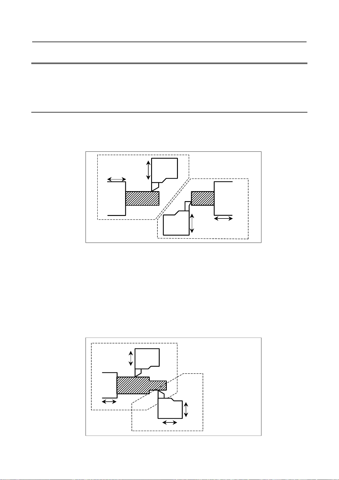
1.CONTROLLED AXIS NC FUNCTION B-64482EN/03
1.11 SUPERIMPOSED CONTROL
In multi-path control, usually, movements are made on the axes of path 1 according to a move command
for path 1, and movements are made on the axes of path 2 according to a move command for path 2
(independent control in each path). However, the superimposed control function enables the travel
distance on an arbitrary axis of one path to be superimposed on the travel distance on an arbitrary axis of
another path.
Explanation
- Independent control in each path
Movements on the axes (X1, Z1, and so on) of path 1 are made according to a move command for path 1,
and movements on the axes (X2, Z2, and so on) of path 2 are made according to a move command for
path 2.
Machining according to
a program for path 2
Workpiece 2
X2
Z2
Z1
Machining according to
a program for path 1
X1
Workpiece 1
Turret 1
Turret 2
- Superimposed Control
To the travel distance on an axis (slave axis) for which an ordinary move command is executed, the travel
distance on the axis (master axis) of another path is added. Superimposed control resembles synchronous
control. In superimposed control, however, a movement on the slave axis can be specified with a
command for the path to which the slave axis belongs.
The master axis and slave axis may belong to the same path, or the master axis may belong to one axis
and the slave axis may belong to another. Moreover, multiple slave axes can be specified for one master
axis. By parameter setting, the move directions on the master axis and slave axis can be reversed from
each other.
Example)
A move command for the Z1 axis of path 1 is superimposed on the travel distance on the Z2 axis of
path 2.
Z1
Turret 1
X1
Workpiece
Machining according to
a program for path 1
Turret 2
Z2
- 50 -
X2
Machining according to
a program for path 2
Page 75

B-64482EN/03 NC FUNCTION 1.CONTROLLED AXIS
1.12 AXIS SYNCHRONOUS CONTROL
When a movement is made along one axis by using two servo motors as in the case of a large gantry
machine, a command for one axis can drive the two motors by synchronizing one motor with the other.
Moreover, by using a feedback signal from each motor, a positional difference (synchronous error)
between the two motors is detected to compensate for the synchronous error. When a synchronous error
exceeding a set value occurs, a synchronous error check can be made to issue an alarm and stop a
movement along the axis.
An axis used as the reference for axis synchronous control is referred to as a master axis (M-axis), and an
axis along which a movement is made in synchronism with the master axis is referred to as a slave axis
(S-axis).
Y
A
(Slave axis)
Z
X
(Master axis)
Even when synchronous error compensation is not used, the synchronous establishment function can be
used for automatic compensation to eliminate a machine coordinate error in cases such as emergency stop
cancellation.
An external signal can be used to turn synchronization on and off. When synchronization is turned on and
off using an external signal, synchronous error compensation cannot be used.
1.13 ANGULAR AXIS CONTROL
When the angular axis installed makes an angle other than 90° with the perpendicular axis, the angular
axis control function controls the distance traveled along each axis according to the inclination angle as in
the case where the angular axis makes 90° with the perpendicular axis.
Arbitrary axes can be specified as a set of an angular axis and perpendicular axis by parameter setting.
The actual distance traveled is controlled according to an inclination angle. However, a program, when
created, assumes that the angular axis and perpendicular axis intersect at right angles.
+Y'(Hypothetical axis)
θ
Program coordinate system
(Cartesian coordinates)
+Y'
+Y'(Angular axis)
: Inclination angle
θ
+X(Perpendicular axis)
Machine coordinate system
(Angular coordinates)
+Y
+X
+X
- 51 -
Page 76

1.CONTROLLED AXIS NC FUNCTION B-64482EN/03
A
A
1.14 INCLINED ROTARY AXIS CONTROL
The conventional tilted working plane command / tool center point control function / 3-dimensional cutter
compensation / 3-dimensional manual feed are used only for those machines whose tool rotation axis or
table rotation axis is parallel to the basic axis of the basic coordinate system.
Inclined rotary axis control is intended to allow the tilted working plane command / tool center point
control function / 3-dimensional cutter compensation / 3-dimensional manual feed to be applied even
when the tool rotation axis or table rotation axis is inclined with respect to the X-Y plane, a Y-Z plane or
a Z-X plane of the machine coordinate system.
<1> Tool rotation type machine
Z
Z
C
Y
B
C
B
X
X
<2> Table rotation type machine
Z
C
<3> Composite-type machine
C
Y
X
Z
Y
B
Y
Z
X
Y
C
Z
B
X
Y
C
X
Fig. 1.14 (a) Three types of 5-axis machine
The machine shown in Fig. 1.14 (b) has rotary axis B (master) that turns around the Y-axis and rotary axis
C (slave) whose Y-axis is inclined at an angle of 45 degrees on the Y-Z plane.
The tilted working plane command / tool center point control function / 3-dimensional cutter
compensation / 3-dimensional manual feed can be used even for the machine configuration shown in Fig.
1.14 (b).
- 52 -
Page 77
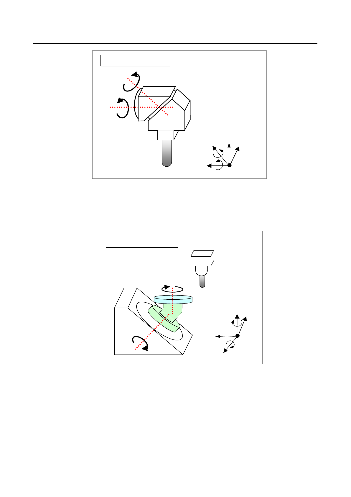
B-64482EN/03 NC FUNCTION 1.CONTROLLED AXIS
Tool rotation type machine
C
B
Z
X
C
Y
B
Fig. 1.14 (b) Example of tool rotation type machine
The machine shown in Fig. 1.14 (c)has rotary axis B (master) whose Y-axis is inclined at an angle of -45
degrees on the Y-Z plane and rotary axis C (slave) that turns around the Z-axis.
The tilted working plane command / tool center point control function / 3-dimensional cutter
compensation / 3-dimensional manual feed can be used even for the machine configuration shown in Fig.
1.14 (c).
Table rotation type machine
C
Z
X
C
Y
B
Fig. 1.14 (c) Example of table rotation type machine
B
The machine shown in Fig. 1.14 (d) has tool rotation axis B whose Y-axis is inclined at an angle of 45
degrees on the Y-Z plane and table rotation axis C that turns around the Z-axis.
The tilted working plane command / tool center point control function / 3-dimensional cutter
compensation / 3-dimensional manual feed can be used even for the machine configuration shown in Fig.
1.14 (d).
- 53 -
Page 78
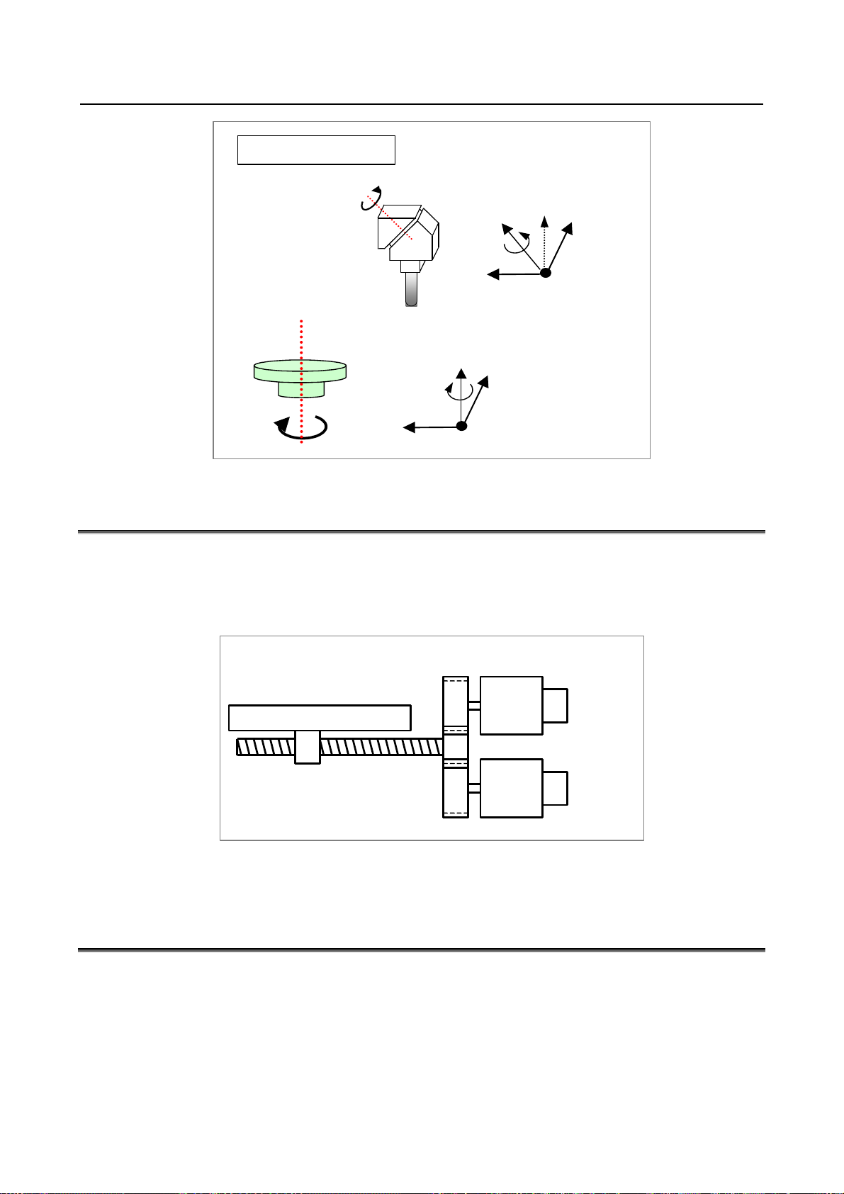
1.CONTROLLED AXIS NC FUNCTION B-64482EN/03
Composite-type
B
B
Y
Z
X
C
C
Fig. 1.14 (d) Example of composite-type machine
Y
Z
X
1.15 TANDEM CONTROL
If a single motor cannot produce sufficient torque to move a large table, for example, this function allows
two motors to be used. By means of this function, two motors can be used to perform movement along a
single axis.
Positioning is carried out only for the master axis. The slave axis is used only to produce a torque. By
means of this function, double the amount of torque can be obtained.
Ta bl e
Ball screw
Main motor
Sub motor
The CNC generally processes the two axes of tandem control as a single axis. In the management of servo
parameters and the monitoring of servo alarms, however, the two axes are handled individually.
1.16 TANDEM DISTURBANCE ELIMINATION CONTROL
This function suppresses vibration caused by interference between the main axis and sub-axis in position
tandem control (feed axis synchronization).
- 54 -
Page 79
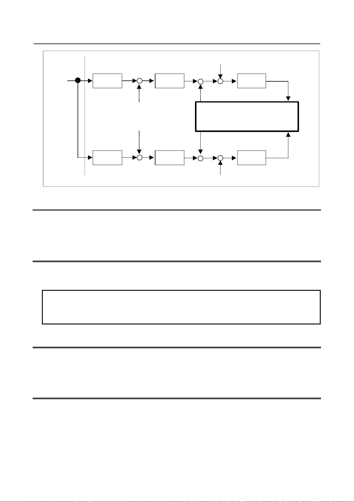
B-64482EN/03 NC FUNCTION 1.CONTROLLED AXIS
Disturbance
+
+
+
Main motor
Kt/Jm⋅s
Velocity fbm
NC command
Servo
Position
control
Main axis
+
-
Veloci ty f bm
+
Velocity
control
Tandem Disturbance
Elimination control
-
+
Disturbance
Sub motor
Kt/Jm⋅s
+
Veloci ty f bs
Sub axis
Position
control
Velocity fbs
-
Velocity
++
control
1.17 TORQUE CONTROL
For a PMC controlled axis, continuous feed based on torque control is performed.
Control on a PMC controlled axis can be switched from position control to torque control, so that the
servo motor outputs torque as specified by the NC.
1.18 POLE POSITION DETECTION FUNCTION
When a motor manufactured by other than FANUC is driven, the magnetic pole position of the motor is
detected.
NOTE
1 This function cannot be used with a vertical axis to which force is applied at all
times.
2 This function cannot be used with an axis when the axis is completely locked.
1.19 CONTROL AXIS DETACH
These signals release the specified control axes from control by the CNC. When attachments are used
(such as a detachable rotary table), these signals are selected according to whether the attachments are
mounted. When multiple rotary tables are used in turn, the tables must use motors of the same model.
1.20 CHOPPING FUNCTION
When contour grinding is performed, the chopping function can be used to grind the side face of a
workpiece. By means of this function, while the grinding axis (the axis with the grinding wheel) is being
moved vertically, a contour program can be executed to initiate movement along other axes.
In addition, a servo delay compensation function is supported for chopping operations. When the grinding
axis is moved vertically at high speed, a servo delay and acceleration/deceleration delay occur. These
delays prevent the tool from actually reaching the specified position.
The servo delay compensation function compensates for any displacement by increasing the feedrate.
Thus, grinding can be performed almost up to the specified position.
- 55 -
Page 80
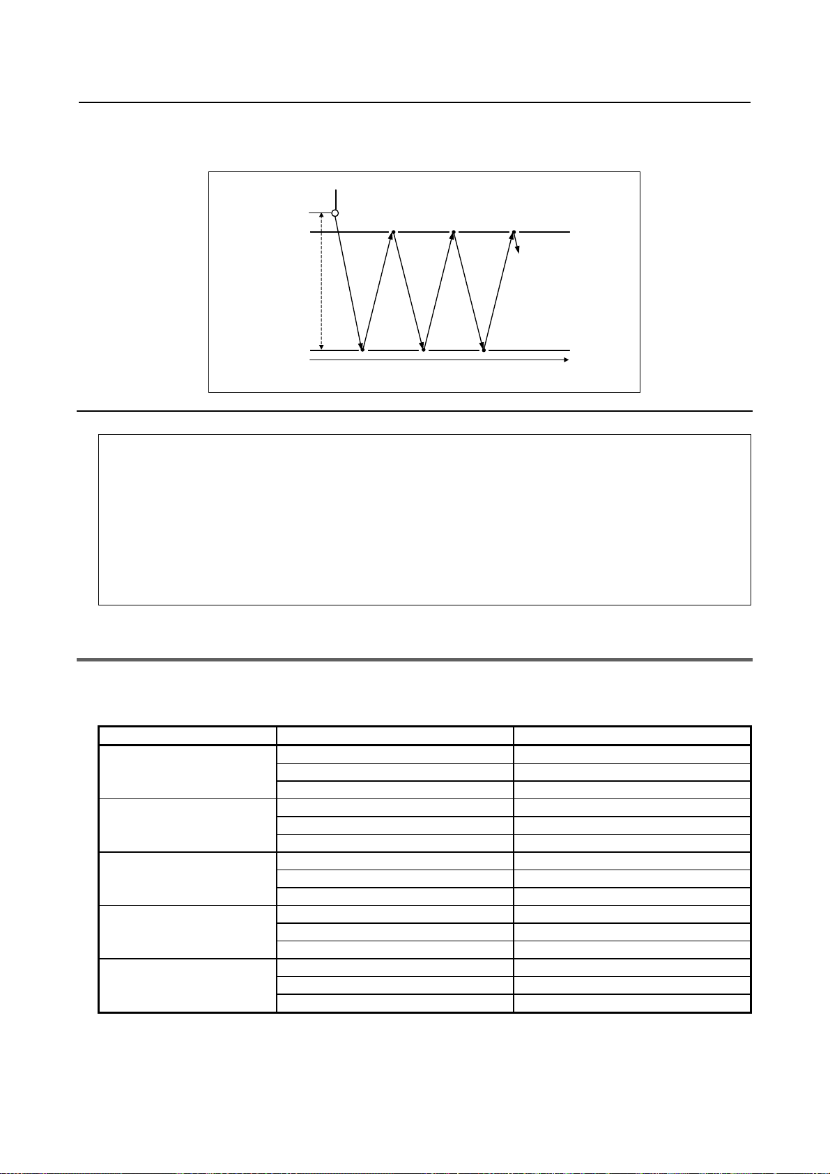
1.CONTROLLED AXIS NC FUNCTION B-64482EN/03
There are two types of chopping functions: that specified by programming, and that activated by signal
input. For details of the chopping function activated by signal input, refer to the manual provided by the
machine tool builder.
Point R
Upper dead point
Lower dead point
Time
Format
G81.1 Z_ Q_ R_ F_ ;
Z : Upper dead point
(For an axis other than the Z-axis, specify the axis address.)
Q : Distance between the upper dead point and lower dead point
(Specify the distance as an incremental value, relative to the upper dead point.)
R : Distance from the upper dead point to point R
(Specify the distance as an incremental value, relative to the upper dead point.)
F : Feedrate during chopping
G80 ; Cancels chopping
1.21 INCREMENT SYSTEM
Five types of increment systems are available as indicated in the table below, and can be chosen from by
parameter setting.
Table 1.21 (a) Increment system
Name of increment system Least input increment Least command increment
0.01 mm 0.01 mm
IS-A
IS-B
IS-C
IS-D
IS-E
The least command increment is either metric or inch depending on the machine tool. Set metric or inch
to the parameter INM.
0.001 inch 0.001 inch
0.01 deg 0.01 deg
0.001 mm 0.001 mm
0.0001 inch 0.0001 inch
0.001 deg 0.001 deg
0.0001 mm 0.0001 mm
0.00001 inch 0.00001 inch
0.0001 deg 0.0001 deg
0.00001 mm 0.00001 mm
0.000001 inch 0.000001 inch
0.00001 deg 0.00001 deg
0.000001 mm 0.000001 mm
0.0000001 inch 0.0000001 inch
0.000001 deg 0.000001 deg
- 56 -
Page 81

B-64482EN/03 NC FUNCTION 1.CONTROLLED AXIS
For selection between metric and inch for the least input increment, G code (G20 or G21) or a setting
parameter selects it.
By parameter setting, a least input increment 10 times greater than a least command increment can be set
as indicated in the table below.
Table 1.21 (b) Increment system
Name of increment system Least input increment Least command increment
0.01 mm 0.001 mm
IS-B
IS-C
IS-D
IS-E
0.001 inch 0.0001 inch
0.01 deg 0.001 deg
0.001 mm 0.0001 mm
0.0001 inch 0.00001 inch
0.001 deg 0.0001 deg
0.0001 mm 0.00001 mm
0.00001 inch 0.000001 inch
0.0001 deg 0.00001 deg
0.00001 mm 0.000001 mm
0.000001 inch 0.0000001 inch
0.00001 deg 0.000001 deg
NOTE
When the increment system is IS-A or pocket calculator type decimal point
programming is used, a least input increment 10 times greater than a least
command increment cannot be set.
1.22 FLEXIBLE FEED GEAR
The detection multiply (DMR) can be extended to set DMR=n/m by using two parameters n and m.
1.23 ARBITRARY COMMAND MULTIPLY
When the detection unit assumes a special value, an arbitrary command multiply can be set using the ratio
of n:m. The setting range is 1/9999 to 9999/1.
1.24 DUAL POSITION FEEDBACK
In general, a machine with a large backlash may operate stably with a semi-closed loop but may vibrate
with a closed loop. This function exercises control so that such a machine can operate stably with a closed
loop as in the case of a semi-closed loop.
The block diagram of dual position feedback control is shown Fig. 1.24 (a).
- 57 -
Page 82

1.CONTROLLED AXIS NC FUNCTION B-64482EN/03
A
MCMD
ER1
+
Σ
-
ER2
+
Σ
- +
Fig. 1.24 (a) Block diagram of dual position feedback control
Position gain
ER
+
+
Position feedback (from motor)
-
Primary delay time
constant
+
Kp
-
Position feedback (from separate detector)
Velocity
control
Velocity feedback
mplifier
Motor
Conversion
coefficient
Separate
detector
1.25 HRV CONTROL
HRV control is a digital servo current control method, and the HRV control system includes servo HRV2,
servo HRV3, and servo HRV4. By employing these control methods, even higher speed, higher precision,
and higher machining speed can be achieved.
• Servo HRV control system
Servo HRV control
HRV control has three features:
(1) A disturbance elimination filter for eliminating low-frequency vibration from a low-rigidity machine
has been developed.
(2) Smoother feed is made possible by a higher-precision servo amplifier and detector.
(3) By employing high-speed DSP, a current control cycle higher than the conventional one is made
achievable with the standard servo system.
HRV filter that can widely match
low-frequency to high-frequency vibration
Servo HRV2 control
Servo HRV3 control
Servo HRV4 control
Higher-speed current control
Higher-precisi
on current
detection
Position
control
Velocity
control
Velocity feedback
HRV
filter
Detector with high response and high precision
HRV
current
control
Current feedback
Servo
amplifier
Motor
- 58 -
Page 83

B-64482EN/03 NC FUNCTION 1.CONTROLLED AXIS
1.26 INCH/METRIC CONVERSION
Either inch or metric input (least input increment) can be selected by G code.
Format
G20 ; Inch input
G21 ; Metric input
Explanation
This G code must be specified in an independent block before setting the coordinate system at the
beginning of the program. Do not specify this G code in the middle of a program.
Moreover, inch/metric conversion is possible in setting data setting.
After the G code for inch/metric conversion is specified, the unit of input data is switched to the least inch
or metric input increment of increment system. The unit of data input for degrees remains unchanged. The
unit systems for the following values are changed after inch/metric conversion:
• Feedrate commanded by F code
• Positional command
• Workpiece origin offset value
• Tool compensation value
• Unit of scale for manual pulse generator
• Movement distance in incremental feed
• Some parameters
When the power is turned on, the G code is the same as that held before the power was turned off.
1.27 INTERLOCK
1.27.1 Start Lock
This function disables movement along axes during automatic operation (memory operation, DNC
operation, or MDI operation).
1.27.2 All-axis Interlock
Feed on all axes can be disabled. If all-axis interlock is applied during movement, a gradual stop occurs.
When the all-axes interlock signal is canceled, movement restarts.
1.27.3 Each-axis Interlock
Feed on a specified axis can be disabled, independent of other axes. If each-axis interlock is applied to an
axis during cutting feed, a gradual stop occurs on all axes of the movable machine section.
When the interlock signal is canceled, movement restarts.
1.27.4 Each-axis Direction Interlock
For each axis, axial movement can be disabled in a specified axis direction only. If each-axis interlock is
applied to an axis during cutting feed, a gradual stop occurs on all axes of the movable machine section.
When the interlock signal is canceled, movement restarts.
- 59 -
Page 84

1.CONTROLLED AXIS NC FUNCTION B-64482EN/03
1.27.5 Block Start Interlock
During automatic operation, the start of the next block can be disabled. A block whose execution has
already been started continues to be executed up to the end of the block.
When block start interlock is canceled, the execution of the next block starts.
1.27.6 Cutting Block Start Interlock
During automatic operation, the start of a block including a move command other than a command for
positioning can be disabled.
When cutting block start interlock is canceled, the execution of the next block starts.
If spindle rotation is specified or the spindle speed is changed, the next cutting block can be executed at
the desired spindle speed by applying cutting block start interlock until the spindle reaches the desired
speed.
1.28 MACHINE LOCK
1.28.1 All-axis Machine Lock
The change of the position display can be monitored without moving the machine.
When all-axis machine lock signal is set to 1, output pulses (move commands) to the servo motors are
stopped in manual or automatic operation. The commands are distributed, however, updating the absolute
and relative coordinates. The operator can therefore check if the commands are correct by monitoring the
position display.
Machine lock during operation can be enabled even in the middle of block execution.
1.28.2 Each-axis Machine Lock
With the each-axis machine lock signal, machine lock can be applied to each axis.
1.29 EMERGENCY STOP
An emergency stop stops all commands and instantly stops the machine. Connect the emergency stop
signal to both of the control unit side and servo unit side.
When an emergency stop is applied, servo system activation is canceled, and the servo ready signal is
turned off. However, the travel distance of the machine during that time is reflected in the current position,
so that the position data is not lost (follow-up). If the position detection system is normal, operation can
be restarted after emergency stop cancellation without performing a reference position return operation
again.
1.30 OVERTRAVEL
When the tool tries to move beyond the stroke end set by the machine tool limit switch, the tool
decelerates and stops because of working the limit switch and an OVER TRAVEL alarm is displayed.
An overtravel signal is provided for each direction on each axis.
- 60 -
Page 85
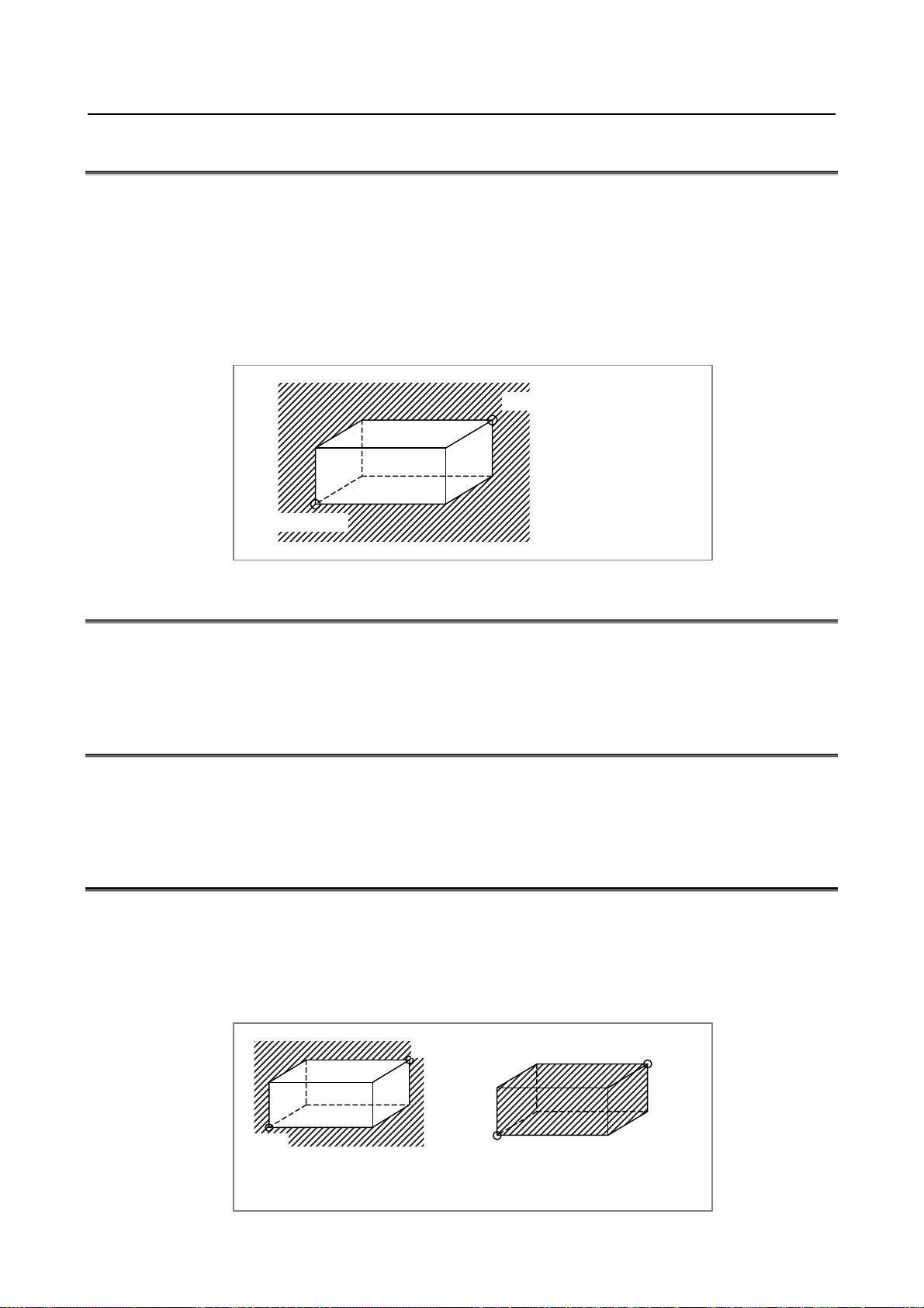
B-64482EN/03 NC FUNCTION 1.CONTROLLED AXIS
1.31 STORED STROKE CHECK 1
A machine movable range is set with coordinates in the machine coordinate system in parameters. If the
machine attempts to move beyond the range, it is decelerated and stopped and an alarm is displayed.
This function is enabled after manual reference position return is performed after power-on.
It can be used instead of an overtravel limit switch (hardware component).
When both functions are used, both are valid.
Unlike an overtravel limit switch, this function checks whether the position at which the machine is
stopped after decelerated from the current position is beyond the range.
The stroke check 1 release signal common to all axes can be set to 1 so that the control unit does not
make stroke check 1.
(X1, Y1, Z1, ...)
The forbidden area is
shaded.
(X2, Y2, Z2, ...)
1.32 STORED STROKE CHECK 1 AREA EXPANSION
In stored stroke check 1, up to eight different forbidden areas can be defined and selected.
Since the number of selectable forbidden areas increases, different forbidden areas can be used for
different machine specifications.
1.33 STROKE LIMIT EXTERNAL SETTING
When a tool is changed, the tool tip is aligned with the end of the limit area and signals are input. This
operation sets the machine position (machine coordinates) at that time as the limit position in stored
stroke check parameters. A setting signal is provided for each direction of each axis.
1.34 STORED STROKE CHECK 2 (G22, G23)
For stored stroke check 2, the outside or inside of the area specified by parameters or a program is defined
as the forbidden area. As a limit position, specify a distance from the origin of the machine coordinate
system. This function is enabled after manual reference position return is performed at power-on. When
the limits are specified in a program, they can be set for the X-, Y-, and Z-axes. For this reason, the
forbidden area can be changed according to the workpiece. Whether to define the inside or outside of the
specified area as the forbidden area is determined by setting the corresponding parameter.
(X,Y,Z)
(X,Y,Z)
(I,J,K)
When the outside of the
specified area is defined as
the forbidden area.
- 61 -
(I,J,K)
When the inside of the
specified area is defined as
the forbidden area.
Page 86

1.CONTROLLED AXIS NC FUNCTION B-64482EN/03
Format
G22 X_ Y_ Z_ I_ J_ K_ ; Stored stroke check 2 on
X, Y, Z : Coordinates in the + direction of stored stroke check 2
I, J, K : Coordinates in the - direction of stored stroke check 2
The address is X, Y, Z, I, J, or K. X and I, Y and J, and Z and K specify a forbidden area
for the X-axis, Y-axis, and Z-axis of the basic three axes, respectively. If an address is
omitted, a stroke check is make according to the parameter settings.
G23 ; Stored stroke check 2 off
1.35 STORED STROKE CHECK 3
The inside of a parameter-set area is a forbidden area.
(X1,Y1,Z1)
(X2,Y2,Z2)
When the inside of the specified area is
defined as the forbidden area.
1.36 STROKE LIMIT CHECK BEFORE MOVE
During automatic operation, before the movement specified by a given block is started, whether the tool
enters the inhibited area defined by stored stroke check 1, 2, or 3 is checked by determining the
coordinate of the end point from the current position of the machine and a specified amount of travel. If
the tool is found to enter the inhibited area defined by a stored stroke limit, the tool is stopped
immediately upon the start of movement for that block, and an alarm is displayed.
1.37 CHUCK AND TAIL STOCK BARRIER
T
The chuck and tail stock barrier function prevents damage to the machine by checking whether the tool
tip interferes with either the chuck or tail stock.
Specify an area into which the tool may not enter (entry-prohibition area). This is done using the special
setting screen, according to the shapes of the chuck and tail stock. If the tool tip should enter the set area
during a machining operation, this function stops the tool and outputs an alarm message.
The tool can be removed from the prohibited area only by retracting it in the direction from which the tool
entered the area.
This function can be enabled or disabled by G22 (stored stroke check 2 on), G23 (stored stroke check 2
off), and a machine-side signal.
G code Tail stock barrier signal Tail stock barrier Chuck barrier
G22
G23
0 Valid Valid
1 Invalid Valid
0 Invalid Invalid
1 Invalid Invalid
- 62 -
Page 87

B-64482EN/03 NC FUNCTION 1.CONTROLLED AXIS
X
Explanation
- Chuck figure definition
- Chuck holding the
outer face of a tool
L
L1
W
W1
X
A
- Chuck holding the
inner face of a tool
CX
L
A
W1
W
L1
X
CX
Workpiece coordinate
system origin
Note) The hatched areas indicate entry-inhibition areas.
Symbol Description
TY Chuck-shape selection (0: Holding the inner face of a tool, 1: Holding the outer face of a tool)
CX Chuck position (along X-axis)
CZ Chuck position (along Z-axis)
L Length of chuck jaws
W Depth of chuck jaws (radius)
L1 Holding length of chuck jaws
W1 Holding depth of chuck jaws (radius)
- Tail stock figure definition
TZ
CZ
Z
CZ
Z
Workpiece coordinate
system origin
L
L1
D3
L2
D2
D1 D
Z
Workpiece
B
Workpiece
coordinate system
origin
Symbol Description
TZ Tail stock position (along the Z-axis)
L Tail stock length
D Tail stock diameter
L1 Tail stock length (1)
D1 Tail stock diameter (1)
L2 Tail stock length (2)
D2 Tail stock diameter (2)
D3 Tail stock hole diameter (3)
- 63 -
Page 88

1.CONTROLLED AXIS NC FUNCTION B-64482EN/03
1.38 CHECKING THE STORED STROKE DURING THE TIME
FROM POWER–ON TO THE REFERENCE POSITION
ESTABLISHMENT
This function stores the machine coordinates present immediately before the power is turned off.
Therefore, immediately after the power is turned on again, this function can restore the approximate
machine coordinates and enables the function for checking the stored stroke during the time from power–
on to the reference position establishment.
Even before the reference position is established by manual reference position return, the stored stroke
check can be performed using approximate machine coordinates.
1.39 STROKE LIMIT AREA CHANGING FUNCTION
This function can be used to rewrite the parameters that set the + side coordinate value and the - side
coordinate values of the stroke limits even when the axis is traveling. The parameters can be rewritten by
the PMC window function (WINDW: SUB52), FOCAS2, and a C Language Executor. The new stroke
limit range is enabled immediately after the parameters are rewritten by any of these functions.
The machining cycle time can be reduced because this function can rewrite parameters even if some axes
are moving.
1.40 ROTATION AREA INTERFERENCE CHECK
This function checks the tool post and chucks for any interference to bring the machine to a stop safely.
Four groups of interference check areas can be set; each group can be specified by combining rectangular
areas together.
- 64 -
Page 89

B-64482EN/03 NC FUNCTION 1.CONTROLLED AXIS
A
A
X
Interference check group A
Interference check
Interference check
Interference check
Interference check group D
Interference check
Interference check
Interference check group B
Interference check group C
For each interference check group, the following are possible:
(1) Up to four rectangles can be set.
(2) The entire group moves with movement along two axes set in parameters. The entire group can be
rotated with rotation about the rotation axis set in a parameter.
(3) Rectangles that are to be rotated and those that are not to be rotated with movement along the
rotation axis can be set with parameters.
1.41 MIRROR IMAGE
Mirror image can be applied to each axis, either by signals or by parameters (setting input is acceptable).
All movement directions are reversed during automatic operation along axes to which a mirror image is
applied.
B
B’
0
Mirror image ON relative to X-axis at point
Mirror image (Example for lathe system)
However, the following directions are not reversed:
• Direction of manual operation and direction of movement, from the intermediate position to the
reference position during automatic reference position return (for the machining center system and
lathe system)
- 65 -
Z
Page 90
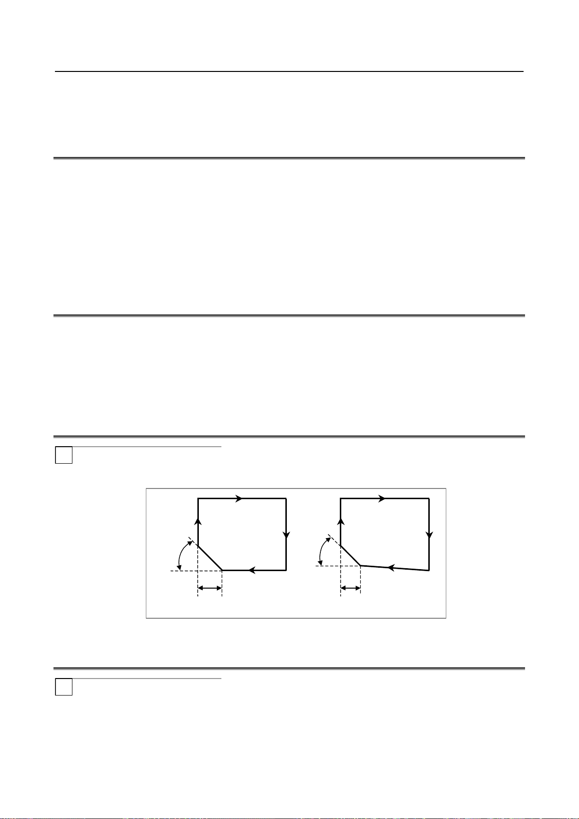
1.CONTROLLED AXIS NC FUNCTION B-64482EN/03
A
A
• Shift direction for boring cycles (G76 and G87) (for machining center system only)
Signals indicate whether mirror image is applied to each axis. System variable contains the same
information.
1.42 FOLLOW-UP
If the machine moves in the state in which position control on controlled axes is disabled (during servooff, emergency stop, or servo alarm), feedback pulses are accumulated in the error counter. The CNC
reflects the machine movement corresponding to the error count in the current position managed by the
CNC. This operation is referred to as follow-up. When follow-up is performed, the current position
managed by the CNC does not shift from the actual machine position.
So, operation can be restarted after emergency stop cancellation or servo alarm cancellation without
performing a reference position return operation again.
You can select whether to perform follow-up for axes when the servo is turned off.
Follow-up is always performed during emergency stop or a servo alarm.
1.43 SERVO OFF / MECHANICAL HANDLE FEED
Place the controlled axes in the servo off state, stop the current to the servo motor, which disables
position control. However, the position detection feature functions continuously, so the current position is
not lost.
These signals are used to prevent the servo motors from overloading when the tools on the axes are
mechanically clamped under certain machining conditions on the machine, or to move the machine by
driving the motors by mechanical handles.
1.44 CHAMFERING ON/OFF
T
In the threading cycle (G76), which is a multiple repetitive cycle for turning, and in the threading cycle
(G92), which is a canned cycle, threading can be selected with the chamfering signal.
pprox.
45
°
r : Threading amount
Fig. 1.44 (a) Straight threading and taper threading
pprox.
45
°
r
r
1.45 INTERFERENCE CHECK FOR EACH PATH
T
When tool posts on individual paths machine the same workpiece simultaneously, the tool posts can
approach each other very closely. If the tool posts interfere with each other due to a program error or any
other setting error, a serious damage such as a tool or machine destruction can occur.
If such a command that causes tool posts of paths to interfere with each other is specified, this function
gradually stops the tool posts before the tool posts actually interfere with each other.
- 66 -
Page 91

B-64482EN/03 NC FUNCTION 1.CONTROLLED AXIS
The contours and shapes of the tool posts on individual paths are checked to determine whether or not an
interference occurs.
This function enables an interference check between two paths or interference check among multiple
paths. Which check to make can be determined by parameter setting.
Tool post 2
Tool post 1
To make a path interference check, data including the relationships between the tool posts on individual
paths and interference forbidden areas (that is, tool shapes) needs to be set.
Based on the interference forbidden areas of the tool currently selected on the tool post of each path and
tool posts, an inter-path interference check determines whether the tools and tool posts interfere with each
other, by checking whether those forbidden areas overlap each other as a result of movement of each tool
post. If an interference occurs, the interfering tool posts gradually stop with an alarm.
1.46 UNEXPECTED DISTURBANCE TORQUE DETECTION
FUNCTION
Machine collision, defective, and damaged cutters cause a large load torque on the servo and spindle
motors, compared with normal rapid traverse or cutting feed. This function detects the disturbance torque
on the motors and sends this value as an estimated load torque to the PMC. If the detected disturbance
torque value is abnormally great compared with the value specified in the parameter, the function stops
the servo motor as early as possible or reverses the motor by an appropriate value specified in a parameter,
in order to minimize possible damage to the machine.
The unexpected disturbance torque detection function is further divided as follows:
(1) Estimated disturbance torque output function
The CNC is always calculating the estimated disturbance torque for the motor (excluding
acceleration/deceleration torque). The estimated disturbance torque output function enables the PMC
to read the calculated torque using the window function.
(2) Unexpected disturbance torque detection alarm function
This function stops motors or reverses them by an amount specified in a parameter, causing the CNC
to output an alarm, whenever the disturbance torque is greater than the value specified in a
parameter. (The function to reverse motors is effective only for servo motors.)
Unexpected disturbance torque detection can also be disabled only for specific axes by using parameter
for the unexpected disturbance torque detection function and unexpected disturbance torque detection
ignore signals. (This function is effective only for servo motors.)
- 67 -
Page 92

1.CONTROLLED AXIS NC FUNCTION B-64482EN/03
1.47 ROTARY AXIS CONTROL
This function controls a rotary axis as specified by an absolute command.
With this function, the sign of the value specified in the command is interpreted as the direction of
rotation, and the absolute value of the specified value is interpreted as the coordinates of the target end
position.
This function is valid when rotary axis roll-over is enabled.
If the parameter is set, an absolute command specified for the roll-over rotary axis is interpreted as
follows: The sign and absolute value of the value specified in the command represent the direction of
rotation and the end position of movement respectively.
1.48 POSITION SWITCH
Position switch signals can be output to the PMC while the machine coordinates along a controlled axes
are within a parameter-specified ranges.
Using parameters, specify arbitrary controlled axes and machine coordinate operating ranges for which
position switch signals are output.
Up to 10 position switch signals can be output.
Parameter can be set to use up to 16 position switch signals.
1.49 HIGH-SPEED POSITION SWITCH
The high-speed position switch function monitors the current position at shorter intervals than the normal
position switch function to output a high-speed precise position switch signal.
In the same way as for the normal position switch function, using parameters, specify arbitrary controlled
axes and machine coordinate operating ranges for which position switch signals are output.
Up to 6 high-speed position signals can be output. Parameter can be set to use up to 16 high-speed
position switch signals.
1.50 DIRECTION-DEPENDENT TYPE HIGH-SPEED POSITION
SWITCH
The high-speed position switch function monitors the machine coordinates and move direction to output
high-speed position switch signals.
Two machine coordinates are monitored. When the tool passes through one coordinate in the specified
direction, the high-speed position switch signal is set to 1. When it passes through the other coordinate in
the specified direction, the signal is set to 0.
The output mode of high-speed position switch signals (normal type or direction-dependent type) is set
using parameters.
Notes
NOTE
This function is an optional function. Order the options for high-speed position
switch and direction-dependent type high-speed position switch.
- 68 -
Page 93
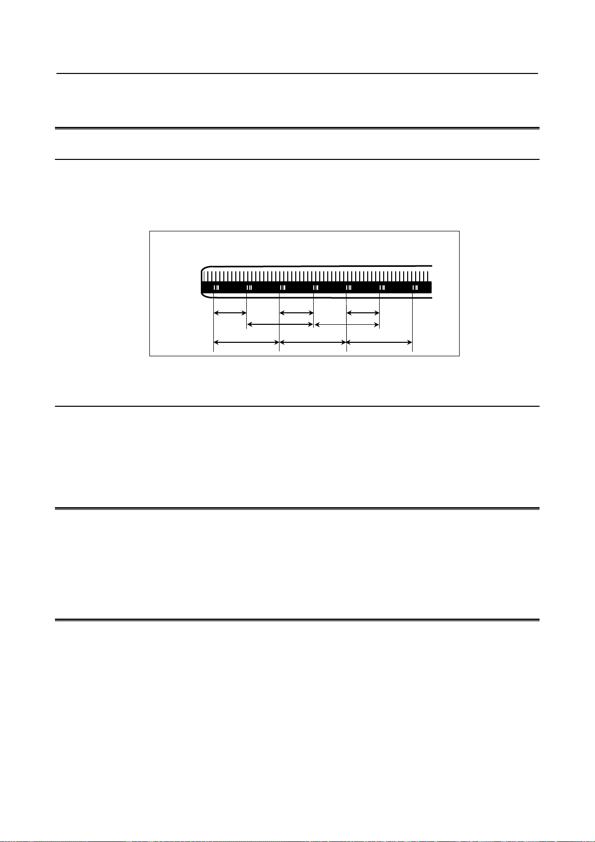
B-64482EN/03 NC FUNCTION 1.CONTROLLED AXIS
1.51 LINEAR SCALE WITH ABSOLUTE ADDRESS
REFERENCE MARK
1.51.1 Linear Scale Interface with Absolute Address Reference Mark
With this function, an absolute position can be identified if the interval of reference marks is known,
because the intervals of two reference marks (one-rotation signals) differ from each other by a certain
distance. This CNC measures one-rotation signal intervals by making a slight movement on an axis to
calculate an absolute position. So, a reference position can be established without making a movement to
the reference position on the axis.
Reference
mark 1
Reference
mark 2
Reference
mark 1
Reference
mark 2
Reference
mark 1
Reference
mark 2
10.02 10.04
20.02
20.00
20.00
10.06
20.02
20.00
1.51.2 Linear Scale with Absolute Address Reference Mark
Expansion
When a G00 command is specified or a move command based on jog feed is specified, this function
enables a reference mark interval measurement to be made automatically in order to establish a reference
position.
1.52 LINEAR SCALE WITH DISTANCE-CODED REFERENCE
MARKS (SERIAL)
By using High-resolution serial output circuit for the linear scale with distance-coded reference marks
(serial), the CNC measures the interval of referenced mark by axis moving of short distance and
determines the absolute position.
This function enables high-speed high-precision detection by using High-resolution serial output circuit.
It is available that using maximum stroke 30 meters length.
1.53 ABSOLUTE POSITION DETECTION
An absolute position detector (absolute pulse coder) is an incremental pulse coder with an absolute
counter. It detects the absolute position based on the value of the absolute counter. For an axis on which
an absolute position detector is mounted, no reference position return is required at power-on because the
machine position is always stored with batteries if the power to the CNC is turned off.
When the machine position has been brought into correspondence with the absolute position detector, the
current position is read from the absolute counter at CNC power on and the machine and workpiece
coordinate systems are automatically set using the value. In this case, you can immediately start automatic
operation.
Restrictions described in the OPERATOR’S MANUAL and others that include those listed below are
removed:
• "Reference position return is required after power-on."
• "The CNC can be used after reference position return is performed after power-on."
- 69 -
Page 94

1.CONTROLLED AXIS NC FUNCTION B-64482EN/03
1.54 TEMPORARY ABSOLUTE COORDINATE SETTING
In the full closed system with an inner absolute position pulse coder (serial pulse coder) and an
incremental scale, the position is set by using absolute position data from the inner absolute position pulse
coder at the power on sequence. After that, the position is controlled with incremental data from the
incremental scale. The position just after power on sequence is rough, and the manual reference position
return is required to get the accurate position.
Absolute position detection
General position control
With this function, the position at the power on is rough, but the following functions are available before
the reference position return.
• Stroke limit check
• Position switch
CNC
at power on
The system with the Temporary Absolute Coordinate Setting
Absolute Serial
Pulse Coder
Incremental
Scale
1.55 DUAL CHECK SAFETY
Setup for machining, which includes attaching and detaching a workpiece to be machined, and moving it
to the machining start point while viewing it, is performed with the protection door opened. The dual
check safety function provides a means for ensuring a high level of safety with the protection door opened.
The simplest method of ensuring safety when the protection door is open is to shut off power to the motor
drive circuit by configuring a safety circuit with a safety relay module. In this case, however, no
movements can be made on a move axis (rotation axis). Moreover, since the power is shut off, some time
is required before machining can be restarted. This drawback can be corrected by adding a motor speed
detector to ensure safety. However, the addition of an external detector may pose a response problem, and
the use of many safety relay modules results in a large and complicated power magnetics cabinet circuit.
With the dual check safety function, two independent CPUs built into the CNC monitor the speed and
position of motors in dual mode. An error in speed and position is detected at high speed, and power to
the motor is shut off via two independent paths. Processing and data related to safety is cross-checked by
two CPUs. To prevent failures from being built up, a safety-related hardware and software test must be
conducted at certain intervals time.
The dual check safety system need not have an external detector added. Instead, only a detector built into
a servo motor or spindle motor is used. This configuration can be implemented only when those motors,
detectors built into motors, and amplifiers that are specified by FANUC are used. When an abnormality
related to safety occurs, the dual check safety function stops operation safely.
The dual check safety function ensures safety with the power turned on, so that an operator can open the
protection door to work without turning off the power. A major feature of the dual check safety function
is that the required time is very short from the detection of an abnormality until the power is shut off. A
cost advantage of the dual check safety function is that external detectors and safety relays can be
eliminated or simplified.
- 70 -
Page 95

B-64482EN/03 NC FUNCTION 1.CONTROLLED AXIS
If a position or speed mismatch is detected by a cross-check using two CPUs, the safety function of the
Dual Check Safety works the power to be shut off (MCC off) to the motor drive circuit.
1.56 FUNCTION OF DECELERATION STOP IN CASE OF
POWER FAILURE
If a power failure occurs during an axial movement, this function stops the movement by decreasing the speed
on each axis at a rate specified in parameter. This function prevents the machine from being damaged by an
overrun.
1.57 CORRESPONDENCE OF ROTARY SCALE WITHOUT
ROTARY DATA
This manual describes how to deal with an absolute position detector (absolute pulse coder) or a rotary
scale with distance-coded reference marks (serial), when the rotary scale without rotary data is used, such
as Heidenhain rotary scale RCN223, RCN723, RCN220, or Futaba rotary scale FRR902L3DB.
1.58 FLEXIBLE SYNCHRONIZATION CONTROL
1.58.1 Flexible Synchronization Control
This function is provided for those machines like hobbing machines that require the synchronization of
various multiple gear ratios.
Synchronization with this function enables up to four pairs to be operated independently and
simultaneously. This achieves special functions for hobbing machines such as the synchronization of the
hobbing axis and a single workpiece axis, Z - C synchronization in helical gear cutting, and Y- C
synchronization in a hobbing axis shift.
Specifications for flexible synchronization control are as follows:
1) A master axis number, a slave axis number, and a gear ratio are set in parameters.
2) There can be up to four groups to these parameters. Synchronization of the four groups can be
executed at the same time.
3) A single slave axis can be specified for multiple master axes.
4) Synchronization is started and canceled with DI signals from the PMC.
If DI signals are to be switched during automatic operation, this needs to be performed with an M
code set in a parameter.
5) Two Cs axes can be used as master and slave axes.
- 71 -
Page 96

1.CONTROLLED AXIS NC FUNCTION B-64482EN/03
r
r
r
r
r
r
- Block diagram
Slave axis
Command
pulse
+
Synchronization switch
-
Position
control
Spindle amplifie
or servo amplifie
Spindle motor (Cs axis)
or servo moto
Detecto
K
Master axis
Command
pulse
+
K: Synchronization coefficient
Position
control
-
Spindle amplifier
or servo amplifie
Spindle motor (Cs axis)
or servo moto
Detector
1.58.2 Automatic Phase Synchronization for Flexible Synchronous
Control
Overview
This function applies acceleration/deceleration when the start or cancellation of synchronization is
specified in flexible synchronous control.
This acceleration/deceleration allows synchronization to be started or canceled while the tool is moving
along the master axis.
This function can also execute automatic phase synchronization so that the slave axis machine coordinate
position at the start of synchronization matches the machine coordinate system zero point of the master
axis (the machine coordinate is 0).
Notes
NOTE
1 The next block is not executed until acceleration/deceleration at the start or
cancellation of synchronization is completed during automatic operation.
2 Due to an error produced when the output pulses for the slave axis are
calculated, the phase of the slave axis may not be matched by least input
increment. This error is not accumulated.
3 This function is disabled in the following functions:
High-speed cycle machining
•
AI contour control I
•
AI contour control II
•
4 This function is an optional function. Order the options for flexible synchronous
control and automatic phase synchronization for flexible synchronous control.
1.58.3 Inter-path Flexible Synchronous Control
Overview
Inter-path flexible synchronous control enables flexible synchronous control between axes in different paths
in a multi-path system.
Up to four slave axes can be specified in one path.
An axis in another path can be specified as the master axis of each slave axis.
Synchronization for all synchronization pairs in all paths can be executed simultaneously.
- 72 -
Page 97
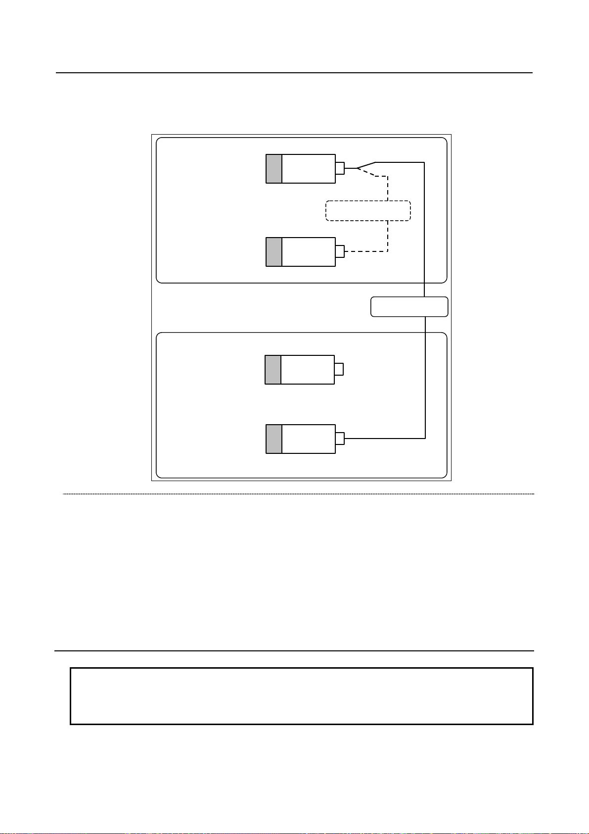
B-64482EN/03 NC FUNCTION 1.CONTROLLED AXIS
Example)
In a multi-path system with the following axis configuration, not only synchronization between the
C1 axis in path 1 (master axis) and the A1 axis in path 1 (slave axis), but also synchronization
between the C1 axis in path 1 (master axis) and the A2 axis in path 2 (slave axis) can be performed.
Path 1
C1 axis
(workpiece axis)
Master
Synchronization
A1 axis
(tool axis)
Path 2
C2 axis
A2 axis
(tool axis)
Slave
Synchronization
Slave
Restrictions
The following functions cannot be specified in the inter-path flexible synchronous mode.
If any of these functions is specified in the inter-path flexible synchronous mode, alarm is issued.
Reference return in Cs contouring control (G00, G28)
•
•
Skip function (G31)
Automatic tool length measurement/Automatic tool offset function
•
•
Automatic reference return operation of low-speed type (G28)
High-speed program check function
•
These functions can be specified when flexible synchronous control and the inter-path flexible
synchronous mode are turned off.
Notes
NOTE
Inter-path flexible synchronous control is an optional function. Specify the
options for flexible synchronous control and inter-path flexible synchronous
control.
- 73 -
Page 98

1.CONTROLLED AXIS NC FUNCTION B-64482EN/03
1.58.4 Chopping Function by Flexible Synchronous Control
M
This function enables the chopping of simultaneous 2-axis control by using a flexible synchronous control
with the chopping.
It is possible to synchronize an axis with a chopping axis. This function is suitable for the taper hole
processing by a grinder etc.
1.58.5 Skip Function for Flexible Synchronous Control
This function enables the skip or high-speed skip signal (in the following explanation, these signals are
collectively called skip signal) for the slave axis that is moved by command of the master axis in the
flexible synchronous control mode.
This function has features such as the following:
• If a skip signal is input while a skip command for flexible synchronous control block is being
executed, this block does not terminate until the specified number of skip signals have been input.
• The machine coordinates assumed when skip signals are input and the number of input skip signals
are stored in specified custom macro variables.
• The total number of the skip signal inputs is stored in another specified custom macro variable.
This function is an optional function.
1.59 AXIS IMMEDIATE STOP FUNCTION
When the movement long an axis must be immediately stopped, the axis immediate stop function stops
the movement using the axis immediate stop start signal and outputs an alarm. In the AI contour control
mode, this function changes the acceleration rate in acceleration/deceleration before interpolation and
stops the movement immediately.
1.60 PIVOT AXIS CONTROL
Overview
This function is intended to control the pivot axis (B-axis), using the ball screw connected to the servo
motor, which has a degree of freedom, as shown in Fig. 1.60.
Ball screw
connection
Pivot axis
Position
encoder
Tool
Ball screw
Servo motor
Rotatable axis
Fig. 1.60
For the rotation axis of an ordinary machine, there is a proportional relation between the rotation angle of
the motor and the position of the rotation axis.
- 74 -
Page 99

B-64482EN/03 NC FUNCTION 1.CONTROLLED AXIS
In this mechanism, in contrast, the proportion of the amount by which the motor (ball screw) rotates to the
position of the rotation axis fluctuates depending on the position of the rotation axis.
A position command is output to operate the servo motor. Also, to detect the rotation angle of the pivot
axis (B-axis), the mechanism is in a fully closed configuration in which a detector is mounted to the
rotation axis itself.
In this mechanism, the speed of the pivot axis (B-axis) may fluctuate. To decrease fluctuations and keep
the actual position gain constant, this function compensates the internal value of the position gain
according to the position of the pivot axis (B-axis).
Limitation
(1) The servo functions below cannot be used together with this function.
• Dual position feedback function
• Semi-Full error monitor
• Machine speed feedback function
• Vibration damping control function
(2) The functions below cannot be used together with the pivot axis.
• Cs Contour Control
• Threading/Feed per revolution by servo motor
• Temporary absolute coordinate setting
(3) The decision on the pivot axis must be set in the parameter.
(4) Composite control of synchronous/composite control cannot be performed.
NOTE
This function is an optional function. The pivot axis control option is required.
1.61 FLEXIBLE PATH AXIS ASSIGNMENT
Overview
This function can remove each controlled axis from the control of each path and assign them as the
controlled axis in the other path.
Using this function makes it possible to control one motor in multiple paths. For example, in the machine
having the axis configuration shown in Example 1 (X1 and Z in path 1 and X2 in path 2), the Z-axis can
be removed from path 1 and assigned to path 2 to form a different axis configuration (X1 in path 1 and
X2 and Z in path 2), therefore requiring no dummy axis unlike composite control.
In the rotary index machine shown in Example 2, axes can be switched among paths.
If an assignment command is issued for an axis yet to be removed, the command waits for the axis to be
removed. In this case, no waiting M code is needed.
The new axis configuration (after flexible path axis assignment) is preserved even after the CNC power is
turned off.
- 75 -
Page 100

1.CONTROLLED AXIS NC FUNCTION B-64482EN/03
(Example 1)
In this example, the Z-axis is switched from path 1 to path 2.
Path 1
Turret 1
X1
Before
Path 1 Path 2
X1 X2
Z
Path 2
Z
Workpiece
Turret 2
X2
After assignment
Path 1 Path 2
X1 X2
Z
- 76 -
 Loading...