

Page 1

-
FANUC Series 21*
MODEL B
FANUC Series 210*- MODEL B
PARAMETER MANUAL
B-63610EN/01
Page 2

• No part of this manual may be reproduced in any form.
• All specifications and designs are subject to change without notice.
In this manual we have tried as much as possible to describe all the various matters.
However, we cannot describe all the matters which must not be done, or which cannot be
done, because there are so many possibilities.
Therefore, matters which are not especially described as possible in this manual should be
regarded as ”impossible”.
This manual contains the program names or device names of other companies, some of
which are registered trademarks of respective owners. However, these names are not
followed by or in the main body.
Page 3

B–63610EN/01
PREFACE
PREFACE
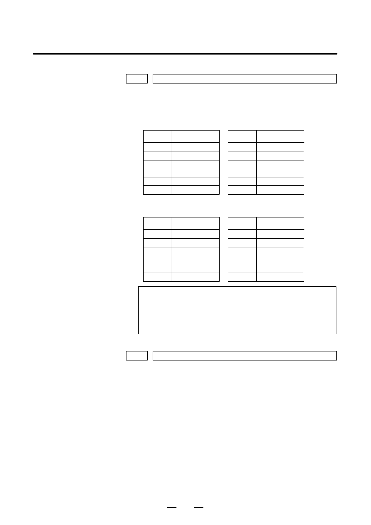
The mode covered by this manual, and their abbreviations are :
Product Name Abbreviations
FANUC Series 21i–TB 21i–TB
FANUC Series 21i–MB 21i–MB
FANUC Series 210i–TB 210i–TB
FANUC Series 210i–MB 210i–MB
Series 21i
Series 210i
NOTE
1 For ease of explanation, the models may be classified as
follows:
T series: 21i–TB/210i–TB
Mseries: 21i–MB/210i–MB
2 Some functions described in this manual may not be applied
to some products.
For details, refer to the DESCRIPTIONS (B–63522EN).
p–1
Page 4

PREFACE
B–63610EN/01
The table below lists manuals related to MODEL A of Series 21i, Series
210i. In the table, this manual is maked with an asterisk (*).
Table 1 Related manuals
Manual name
DESCRIPTIONS B–63522EN
CONNECTION MANUAL (HARDWARE) B–63523EN
CONNECTION MANUAL (FUNCTION) B–63523EN–1
OPERATOR’S MANUAL (For Lathe) B–63604EN
OPERATOR’S MANUAL (For Machining Center) B–63614EN
MAINTENANCE MANUAL B–63525EN
P ARAMETER MANUAL B–63610EN *
Related to Programming
Macro Compiler/Macro Executor
PROGRAMMING MANUAL
C Language Executor PROGRAMMING MANUAL B–62443EN–3
FANUC MACRO COMPILER (For Personal Computer)
PROGRAMMING MANUAL
Manual for CAP (For Lathe)
FANUC Super CAPi T OPERAT OR’S MANUAL B–63284EN
FANUC Symbol CAPi T OPERAT OR’S MANUAL B–63304EN
MANUAL GUIDE PROGRAMMING MANUAL B–63343EN
MANUAL GUIDE OPERA T OR’S MANUAL B–63344EN
Manual for CAP (For Machining Center)
FANUC Super CAPi M OPERAT OR’S MANUAL B–63294EN
MANUAL GUIDE (For Milling) PROGRAMMING MANUAL B–63423EN
MANUAL GUIDE (For Milling) OPERA TOR ’S MANUAL B–63424EN
PMC
PMC Ladder language PROGRAMMING MANUAL B–61863E
PMC C language PROGRAMMING MANUAL B–61863E–1
Loader control
Loader Control CONNECTION MANUAL B–62443EN–2
Related to Board
PROFIBUS–DP Board OPERA T OR’S MANUAL B–62924EN
Ethernet/DATA SERVER Board OPERATOR’S MANUAL B–63354EN
DeviceNet Board OPERA T OR ’S MANUAL B–63404EN
Specification
Number
B–61803E–1
B–66102E
p–2
Page 5

B–63610EN/01
Table of Contents
PREFACE p–1. . . . . . . . . . . . . . . . . . . . . . . . . . . . . . . . . . . . . . . . . . . . . . . . . . . . . . . . . . . . . . . .
1. DISPLAYING PARAMETERS 1. . . . . . . . . . . . . . . . . . . . . . . . . . . . . . . . . . . . . . . . . . . .
2. SETTING PARAMETERS FROM MDI 2. . . . . . . . . . . . . . . . . . . . . . . . . . . . . . . . . . . .
3. INPUTTING AND OUTPUTTING PARAMETERS THROUGH
THE READER/PUNCHER INTERF ACE 4. . . . . . . . . . . . . . . . . . . . . . . . . . . . . . . . . . .
3.1 OUTPUTTING PARAMETERS THROUGH THE READER/PUNCHER INTERFACE 5. . . . . . . .
3.2 INPUTTING PARAMETERS THROUGH THE READER/PUNCHER INTERFACE 6. . . . . . . . . .
4. DESCRIPTION OF PARAMETERS 7. . . . . . . . . . . . . . . . . . . . . . . . . . . . . . . . . . . . . . .
4.1 PARAMETERS OF SETTING 9. . . . . . . . . . . . . . . . . . . . . . . . . . . . . . . . . . . . . . . . . . . . . . . . . . . . . .
4.2 PARAMETERS OF READER/PUNCHER INTERFACE, REMOTE BUFFER,
DNC1, DNC2, AND M–NET INTERFACE 14. . . . . . . . . . . . . . . . . . . . . . . . . . . . . . . . . . . . . . . . . . .
4.2.1 Parameters Common to all Channels 15. . . . . . . . . . . . . . . . . . . . . . . . . . . . . . . . . . . . . . . . . . . . . . . . . .
4.2.2 Parameters of Channel 1 (I/O CHANNEL=0) 16. . . . . . . . . . . . . . . . . . . . . . . . . . . . . . . . . . . . . . . . . . .
4.2.3 Parameters of Channel 1 (I/O CHANNEL=1) 17. . . . . . . . . . . . . . . . . . . . . . . . . . . . . . . . . . . . . . . . . . .
4.2.4 Parameters of Channel 2 (I/O CHANNEL=2) 18. . . . . . . . . . . . . . . . . . . . . . . . . . . . . . . . . . . . . . . . . . .
4.2.5 Parameters of Channel 3 (I/O CHANNEL=3) 18. . . . . . . . . . . . . . . . . . . . . . . . . . . . . . . . . . . . . . . . . . .
4.3 PARAMETERS OF DNC1/DNC2 INTERFACE 21. . . . . . . . . . . . . . . . . . . . . . . . . . . . . . . . . . . . . . . .
4.4 PARAMETERS OF REMOTE DIAGNOSIS 24. . . . . . . . . . . . . . . . . . . . . . . . . . . . . . . . . . . . . . . . . . .
4.5 PARAMETERS OF DNC1 INTERFACE 28. . . . . . . . . . . . . . . . . . . . . . . . . . . . . . . . . . . . . . . . . . . . .
4.6 PARAMETER OF MEMORY CARD INTERFACE 30. . . . . . . . . . . . . . . . . . . . . . . . . . . . . . . . . . . . .
4.7 PARAMETERS OF FACTOLINK 31. . . . . . . . . . . . . . . . . . . . . . . . . . . . . . . . . . . . . . . . . . . . . . . . . . .
4.8 PARAMETERS OF DATA SERVER 33. . . . . . . . . . . . . . . . . . . . . . . . . . . . . . . . . . . . . . . . . . . . . . . . .
4.9 PARAMETERS OF ETHERNET 35. . . . . . . . . . . . . . . . . . . . . . . . . . . . . . . . . . . . . . . . . . . . . . . . . . . .
4.10 PARAMETERS OF POWER MATE CNC MANAGER 36. . . . . . . . . . . . . . . . . . . . . . . . . . . . . . . . . .
4.11 PARAMETERS OF AXIS CONTROL/INCREMENT SYSTEM 37. . . . . . . . . . . . . . . . . . . . . . . . . . .
4.12 PARAMETERS OF COORDINATES 46. . . . . . . . . . . . . . . . . . . . . . . . . . . . . . . . . . . . . . . . . . . . . . . .
4.13 PARAMETERS OF STROKE CHECK 52. . . . . . . . . . . . . . . . . . . . . . . . . . . . . . . . . . . . . . . . . . . . . . .
4.14 PARAMETERS OF THE CHUCK AND TAILSTOCK BARRIER (T SERIES) 57. . . . . . . . . . . . . . .
4.15 PARAMETERS OF FEEDRATE 61. . . . . . . . . . . . . . . . . . . . . . . . . . . . . . . . . . . . . . . . . . . . . . . . . . . .
4.16 PARAMETERS OF ACCELERATION/DECELERATION CONTROL 72. . . . . . . . . . . . . . . . . . . . .
4.17 PARAMETERS OF SERVO 88. . . . . . . . . . . . . . . . . . . . . . . . . . . . . . . . . . . . . . . . . . . . . . . . . . . . . . . .
4.18 PARAMETERS OF DI/DO 113. . . . . . . . . . . . . . . . . . . . . . . . . . . . . . . . . . . . . . . . . . . . . . . . . . . . . . . . .
4.19 PARAMETERS OF MDI, DISPLAY, AND EDIT 117. . . . . . . . . . . . . . . . . . . . . . . . . . . . . . . . . . . . . . .
4.20 PARAMETERS OF PROGRAMS 144. . . . . . . . . . . . . . . . . . . . . . . . . . . . . . . . . . . . . . . . . . . . . . . . . . .
4.21 PARAMETERS OF PITCH ERROR COMPENSATION 153. . . . . . . . . . . . . . . . . . . . . . . . . . . . . . . . .
4.22 PARAMETERS OF SPINDLE CONTROL 164. . . . . . . . . . . . . . . . . . . . . . . . . . . . . . . . . . . . . . . . . . . .
4.23 PARAMETERS OF TOOL COMPENSATION 206. . . . . . . . . . . . . . . . . . . . . . . . . . . . . . . . . . . . . . . . .
4.24 PARAMETERS OF CANNED CYCLES 216. . . . . . . . . . . . . . . . . . . . . . . . . . . . . . . . . . . . . . . . . . . . . .
4.24.1 Parameter of Canned Cycle for Drilling 216. . . . . . . . . . . . . . . . . . . . . . . . . . . . . . . . . . . . . . . . . . . . . . . .
4.24.2 Parameter of Thread Cutting Cycle 222. . . . . . . . . . . . . . . . . . . . . . . . . . . . . . . . . . . . . . . . . . . . . . . . . . . .
4.24.3 Parameter of Multiple Repetitive Canned Cycle 222. . . . . . . . . . . . . . . . . . . . . . . . . . . . . . . . . . . . . . . . . .
4.24.4 Parameters of Peck Drilling Cycle of a Small Diameter 224. . . . . . . . . . . . . . . . . . . . . . . . . . . . . . . . . . . .
4.25 PARAMETERS OF RIGID TAPPING 228. . . . . . . . . . . . . . . . . . . . . . . . . . . . . . . . . . . . . . . . . . . . . . . .
c–1
Page 6

Table of Contents
4.26 PARAMETERS OF SCALING/COORDINATE ROTATION 249. . . . . . . . . . . . . . . . . . . . . . . . . . . . . .
4.27 PARAMETERS OF UNI–DIRECTIONAL POSITIONING 251. . . . . . . . . . . . . . . . . . . . . . . . . . . . . . .
4.28 PARAMETERS OF NORMAL DIRECTION CONTROL 252. . . . . . . . . . . . . . . . . . . . . . . . . . . . . . . .
4.29 PARAMETERS OF INDEXING INDEX TABLE 256. . . . . . . . . . . . . . . . . . . . . . . . . . . . . . . . . . . . . . .
4.30 PARAMETERS OF CUSTOM MACROS 258. . . . . . . . . . . . . . . . . . . . . . . . . . . . . . . . . . . . . . . . . . . . .
4.31 PARAMETERS OF SIMPLE MACROS 265. . . . . . . . . . . . . . . . . . . . . . . . . . . . . . . . . . . . . . . . . . . . . .
4.32 PARAMETERS OF PATTERN DATA INPUT 266. . . . . . . . . . . . . . . . . . . . . . . . . . . . . . . . . . . . . . . . .
4.33 PARAMETERS OF POSITIONING BY OPTIMUM ACCELERATION 267. . . . . . . . . . . . . . . . . . . . .
4.34 PARAMETERS OF SKIP FUNCTION 272. . . . . . . . . . . . . . . . . . . . . . . . . . . . . . . . . . . . . . . . . . . . . . .
4.35 PARAMETERS OF AUTOMATIC TOOL COMPENSATION (T SERIES) AND
AUTOMATIC TOOL LENGTH COMPENSATION (M SERIES) 277. . . . . . . . . . . . . . . . . . . . . . . . . .
4.36 PARAMETERS OF EXTERNAL DATA INPUT/OUTPUT 279. . . . . . . . . . . . . . . . . . . . . . . . . . . . . . .
4.37 PARAMETERS OF RETRACING BY THE MANUAL HANDLE 280. . . . . . . . . . . . . . . . . . . . . . . . .
4.38 PARAMETERS OF GRAPHIC DISPLAY 289. . . . . . . . . . . . . . . . . . . . . . . . . . . . . . . . . . . . . . . . . . . . .
4.38.1 Parameters of Graphic Display/Dynamic Graphic Display 289. . . . . . . . . . . . . . . . . . . . . . . . . . . . . . . . . .
4.38.2 Parameters of Graphic Color 291. . . . . . . . . . . . . . . . . . . . . . . . . . . . . . . . . . . . . . . . . . . . . . . . . . . . . . . . .
4.39 PARAMETERS OF DISPLAYING OPERATION TIME AND NUMBER OF PARTS 293. . . . . . . . . .
4.40 PARAMETERS OF TOOL LIFE MANAGEMENT 297. . . . . . . . . . . . . . . . . . . . . . . . . . . . . . . . . . . . .
4.41 PARAMETERS OF POSITION SWITCH FUNCTIONS 303. . . . . . . . . . . . . . . . . . . . . . . . . . . . . . . . .
4.42 PARAMETERS OF MANUAL OPERATION AND AUTOMATIC OPERATION 307. . . . . . . . . . . . .
4.43 PARAMETERS OF MANUAL HANDLE FEED AND HANDLE INTERRUPTION 309. . . . . . . . . . .
4.44 PARAMETERS OF MANUAL LINE AND ARC FUNCTIONS 312. . . . . . . . . . . . . . . . . . . . . . . . . . .
4.45 PARAMETERS OF REFERENCE POSITION SETTING WITH MECHANICAL
STOPPER 313. . . . . . . . . . . . . . . . . . . . . . . . . . . . . . . . . . . . . . . . . . . . . . . . . . . . . . . . . . . . . . . . . . . . . .
4.46 PARAMETERS OF SOFTWARE OPERATOR’S PANEL 315. . . . . . . . . . . . . . . . . . . . . . . . . . . . . . . .
4.47 PARAMETERS OF PROGRAM RESTART 319. . . . . . . . . . . . . . . . . . . . . . . . . . . . . . . . . . . . . . . . . . .
4.48 PARAMETERS OF HIGH–SPEED MACHINING (HIGH–SPEED REMOTE BUFFER) 320. . . . . . .
4.49 PARAMETERS OF POLYGON TURNING 322. . . . . . . . . . . . . . . . . . . . . . . . . . . . . . . . . . . . . . . . . . .
4.50 PARAMETERS OF AXIS CONTROL BY PMC 328. . . . . . . . . . . . . . . . . . . . . . . . . . . . . . . . . . . . . . .
4.51 PARAMETERS OF ANGULAR AXIS CONTROL 334. . . . . . . . . . . . . . . . . . . . . . . . . . . . . . . . . . . . .
4.52 PARAMETERS OF B–AXIS CONTROL 336. . . . . . . . . . . . . . . . . . . . . . . . . . . . . . . . . . . . . . . . . . . . .
4.53 PARAMETERS OF SIMPLE SYNCHRONOUS CONTROL 339. . . . . . . . . . . . . . . . . . . . . . . . . . . . . .
4.54 PARAMETERS OF CHECK TERMINATION 348. . . . . . . . . . . . . . . . . . . . . . . . . . . . . . . . . . . . . . . . .
4.55 OTHER PARAMETERS 349. . . . . . . . . . . . . . . . . . . . . . . . . . . . . . . . . . . . . . . . . . . . . . . . . . . . . . . . . .
4.56 PARAMETERS OF MAINTENANCE 355. . . . . . . . . . . . . . . . . . . . . . . . . . . . . . . . . . . . . . . . . . . . . . .
4.57 PARAMETERS OF BUILT–IN MACRO 356. . . . . . . . . . . . . . . . . . . . . . . . . . . . . . . . . . . . . . . . . . . . .
4.58 PARAMETERS OF OPERATION HISTORY 360. . . . . . . . . . . . . . . . . . . . . . . . . . . . . . . . . . . . . . . . . .
B–63610EN/01
APPENDIX
A. CHARACTER CODE LIST 367. . . . . . . . . . . . . . . . . . . . . . . . . . . . . . . . . . . . . . . . . . . . . .
c–2
Page 7

B–63610EN/01
1
1. DISPLAYING PARAMETERS
DISPLAYING PARAMETERS
Follow the procedure below to display parameters.
(1) Press the SYSTEM function key on the MDI as many times as
required, or alternatively , press the SYSTEM function key once, then
the PARAM section display soft key. The parameter screen is then
selected.
PARAMETER (FEEDRATE) O0001 N12345
1401 RDR JZR RF0 LRP RPD
0 0 0 0 0 0 0 0
1402 DLF HFC
0 0 0 0 0 0 0 0
1410 DRY RUN FEEDRATE 10000
1411 INIT.CUTTING F 0
1420 RAPID FEEDRATE X 15000
Y 15000
Z 15000
>
MEM STRT MTN FIN *** 10:02:35
[PARAM] [DGNOS] [ PMC ] [SYSTEM] [(OPRT)]
Return menu key Soft key Continuous menu key
POS PROG
SYSTEM MESSAGE GRAPH
Cursor
(2) The parameter screen consists of multiple pages. Use step (a) or (b)
to display the page that contains the parameter you want to display.
(a) Use the page select key or the cursor move keys to display the de-
sired page.
(b) Enter the data number of the parameter you want to display from
the keyboard, then press the [NO.SRH] soft key. The parameter
page containing the specified data number appears with the cursor positioned at the data number. (The data is displayed in reverse video.)
Function key
Soft key display
(section select)
OFFSET
SETTING
CUSTOM
NOTE
If key entry is started with the section select soft keys
displayed, they are replaced automatically by operation
select soft keys including [NO.SRH]. Pressing the [(OPRT)]
soft key can also cause the operation select keys to be
displayed.
>
MEM STRT MTN FIN *** 10:02:34
[NO.SRH] [ ON:1 ] [ OFF:0 ] [+INPUT] [INPUT ]
1
Data entered from
←
the keyboard
Soft key display
←
(section select)
Page 8

2. SETTING PARAMETERS FROM MDI
SETTING P ARAMETERS FROM MDI
2
Follow the procedure below to set parameters.
(1) Place the NC in the MDI mode or the emergency stop state.
(2) Follow the substeps below to enable writing of parameters.
SETTING (HANDY) O0001 N00010
B–63610EN/01
1. To display the setting screen, press the SETTING function key
as many times as required, or alternatively press the SETTING
function key once, then the SETTING section select soft key . The
first page of the setting screen appears.
2. Position the cursor on “P ARAMETER WRITE” using the cursor
move keys.
PARAMETER WRITE = (0:DISABLE 1:ENABLE)
TV CHECK = 0 (0:OFF 1:ON)
PUNCH CODE = 0 (0:EIA 1:ISO)
INPUT UNIT = 0 (0:MM 1:INCH)
I/O CHANNEL = 0 (0–3:CHANNEL NO.)
3. Press the [(OPRT)] soft key to display operation select soft keys.
>
MDI STOP *** *** *** 10:03:02
[NO.SRH] [ ON:1 ] [ OFF:0 ] [+INPUT] [INPUT]
4. To set “PARAMETER WRITE=” to 1, press the ON:1 soft key,
or alternatively enter 1 and press the INPUT soft key . From now
on, the parameters can be set. At the same time an alarm condition (P/S100 PARAMETER WRITE ENABLE) occurs in the
CNC.
(3) T o display the parameter screen, press the SYSTEM function key as
many times as required, or alternatively press the SYSTEM function
key once, then the PARAM section select soft key.
(See “1. Displaying Parameters.”)
(4) Display the page containing the parameter you want to set, and
position the cursor on the parameter. (See “1. Displaying
Parameters.”)
0
← Soft key display
(section select)
(5) Enter data, then press the [INPUT] soft key. The parameter indicated
by the cursor is set to the entered data.
2
Page 9

B–63610EN/01
2. SETTING PARAMETERS FROM MDI
[Example] 12000 [INPUT]
PARAMETER (FEEDRATE) O0001 N00010
1401 RDR JZR RPD
00000000
1402 JRV
00000000
1410 DRY RUN FEEDRATE
1412 0
1420 RAPID FEEDRATEX 15000
Y 15000
Z 15000
>
MDI STOP *** *** ALM 10:03:10
[NO.SRH] [ ON:1 ] [ OFF:0 ] [+INPUT] [INPUT]
12000
Cursor
Data can be entered continuously for parameters, starting at the selected
parameter, by separating each data item with a semicolon (;).
[Example] Entering 10;20;30;40 and pressing the INPUT key assigns values 10, 20,
30, and 40 to parameters in order starting at the parameter indicatedby the
cursor.
(6) Repeat steps (4) and (5) as required.
(7) If parameter setting is complete, set “PARAMETER WRITE=” to 0
on the setting screen to disable further parameter setting.
(8) Reset the NC to release the alarm condition (P/S100).
If an alarm condition (P/S000 PLEASE TURN OFF POWER) occurs
in the NC, turn it off before continuing operation.
3
Page 10

3. INPUTTING AND OUTPUTTING PARAMETERS THROUGH
THE READER/PUNCHER INTERFACE
INPUTTING AND OUTPUTTING PARAMETERS THROUGH THE READER/PUNCHER INTERF ACE
3
This section explains the parameter input/output procedures for
input/output devices connected to the reader/puncher interface.
The following description assumes the input/output devices are ready for
input/output. It also assumes parameters peculiar to the input/output
devices, such as the baud rate and the number of stop bits, have been set
in advance.
B–63610EN/01
4
Page 11

B–63610EN/01
3. INPUTTING AND OUTPUTTING PARAMETERS THROUGH
THE READER/PUNCHER INTERFACE
3.1
OUTPUTTING PARAMETERS THROUGH THE READER/PUNCHER INTERFACE
PARAMETER (FEEDRATE) O0001 N00010
1401 RDR JZR RPD
1402 JRV
1410 DRY RUN FEEDRATE
1412 0
1420 RAPID FEEDRATEX 15000
>
MDI STOP *** *** ALM 10:03:10
[NO.SRH] [ON:1] [OFF:0] [+INPUT] [INPUT]
(1) Select the EDIT mode or set to Emergency stop.
(2) To select the parameter screen, press the SYSTEM function key as
many times as required, or alternatively press the SYSTEM function
key once, then the PARAM section select soft key.
(3) Press the [(OPRT)] soft key to display operation select soft keys, then
press the forward menu key located at the right–hand side of the soft
keys to display another set of operation select keys including
PUNCH.
00000000
00000000
12000
Y 15000
Z 15000
Cursor
State display
Soft key display
(operation select)
(4) Pressing the [PUNCH] soft key changes the soft key display as
shown below:
>
EDIT STOP *** *** *** 10:35:03
[ ] [ ] [ ] [CANCEL] [ EXEC ]
(5) Press the [EXEC] soft key to start parameter output. When
parameters are being output, “OUTPUT” blinks in the state display
field on the lower part of the screen.
>
EDIT STOP *** *** *** 10:35:04 OUTPUT
[ ] [ ] [ ] [CANCEL] [ EXEC ]
(6) When parameter output terminates, “OUTPUT” stops blinking. Press
the RESET key to interrupt parameter output.
← OUTPUT blinking
5
Page 12

3. INPUTTING AND OUTPUTTING PARAMETERS THROUGH
THE READER/PUNCHER INTERFACE
B–63610EN/01
3.2
INPUTTING PARAMETERS THROUGH THE READER/PUNCHER INTERFACE
>
EDIT STOP ALM 10:37:30
[ ] [ READ ] [PUNCH] [ ] [ ]
(1) Place the NC in the emergency stop state.
(2) Enable parameter writing.
1. To display the setting screen, press the SETTING function key
as many times as required, or alternatively press the SETTING
function key once, then the SETTING section select soft key . The
first page of the setting screen appears.
2. Position the cursor on “P ARAMETER WRITE” using the cursor
move keys.
3. Press the [(OPRT)] soft key to display operation select soft keys.
4. To set “PARAMETER WRITE=” to 1, press the ON:1 soft key,
or alternatively enter 1, then press the [INPUT] soft key. From
now on, parameters can be set. At the same time an alarm condition (P/S100 PARAMETER WRITE ENABLE) occurs in the
NC.
(3) To select the parameter screen, press the SYSTEM function key as
many times as required, or alternatively press the SYSTEM key once,
then [PARAM] soft key.
(4) Press the [(OPRT)] soft key to display operation select keys, then
press the forward menu key located at the right–hand side of the soft
keys to display another set of operation select soft keys including
[READ].
–EMS– ALM
← State display
← Soft key display
(5) Pressing the [READ] soft key changes the soft key display as shown
below:
>
EDIT STOP ALM 10:37:30
[ ] [ ] [ ] [CANCEL] [ EXEC ]
–EMS– ALM
(6) Press the [EXEC] soft key to start inputting parameters from the
input/output device. When parameters are being input, “INPUT”
blinks in the state display field on the lower part of the screen.
>
EDIT STOP ALM 10:37:30 INPUT
[ ] [ ] [ ] [CANCEL] [ EXEC ]
–EMS– ALM
(7) When parameter input terminates, “INPUT” stops blinking. Press the
RESET key to interrupt parameter input.
(8) When parameter read terminates, “INPUT” stops blinking, and an
alarm condition (P/S000) occurs in the NC. Turn it off before
continuing operation.
← INPUT blinking
6
Page 13

B–63610EN/01
4
DESCRIPTION OF PARAMETERS
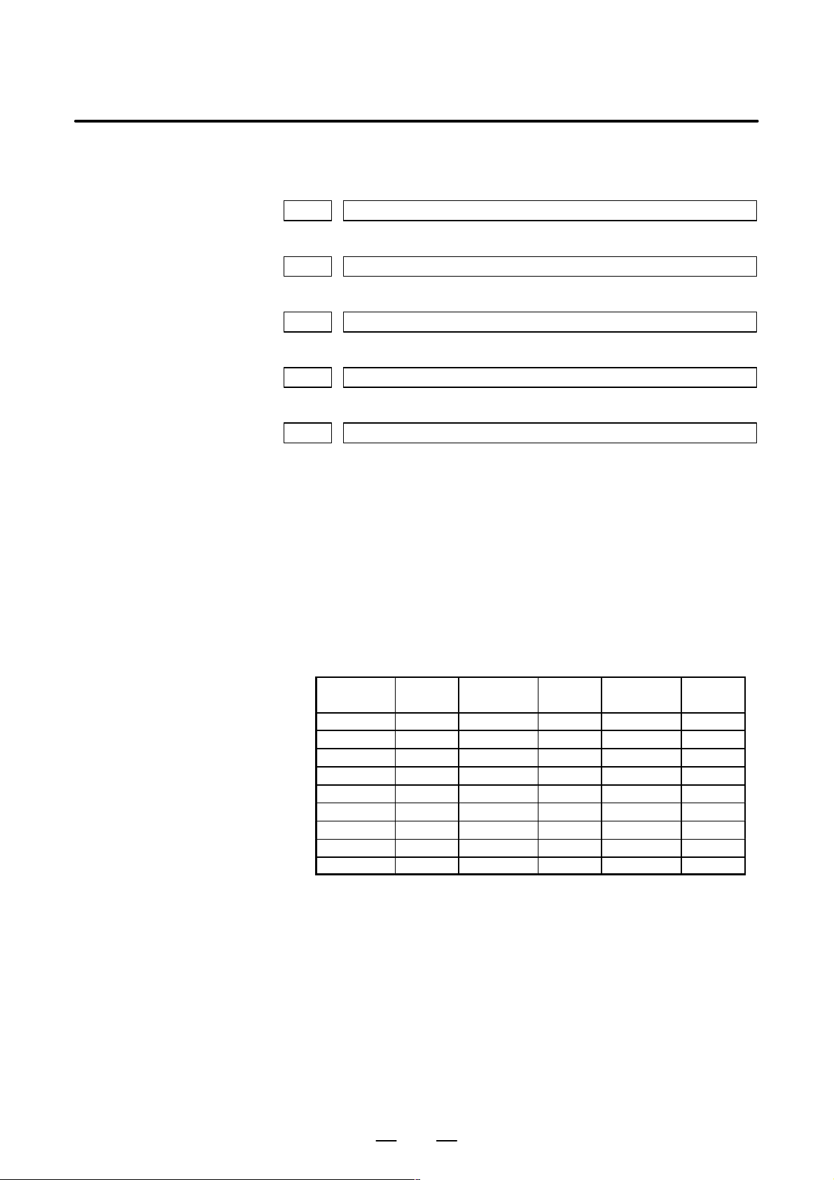
Parameters are classified by data type as follows:
Table 4 Data Types and Valid Data Ranges of Parameters
Data type Valid data range Remarks
Bit
Bit axis
Byte
Byte axis
Word
Word axis
2–word
2–word axis
0 or 1
–128 to 127 In some parameters, signs are
–128 to 127
0 to 255
–32768 to 32767 In some parameters, signs are
–32768 to 32767
0 to 65535
–99999999 to 99999999
4. DESCRIPTION OF PARAMETERS
In some parameters, signs are
ignored.
In some parameters, signs are
ignored.
[Example]
0000
Data No.
1023 Servo axis number of a specific axis
Data No.
NOTE
1 For the bit type and bit axis type parameters, a single data
number is assigned to 8 bits. Each bit has a different
meaning.
2 The axis type allows data to be set separately for each
control axis.
3 The valid data range for each data type indicates a general
range. The range varies according to the parameters. For
the valid data range of a specific parameter, see the
explanation of the parameter.
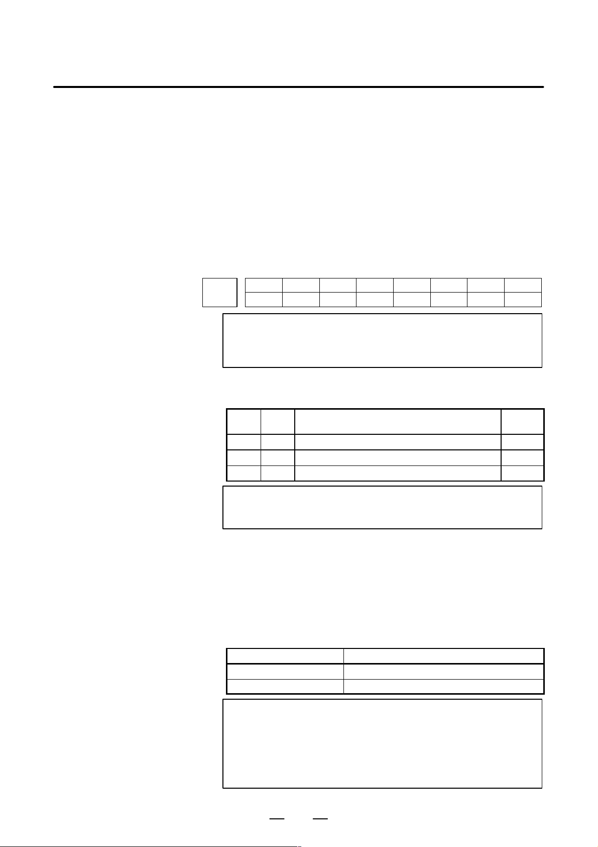
(1) Notation of bit type and bit axis type parameters
#7
#6 #5
SEQ
#4 #3 #2
Data #0 to #7 are bit positions.
INI
#1
ISO
(2) Notation of parameters other than bit type and bit axis type
Data.
#0
TVC
7
Page 14

4. DESCRIPTION OF PARAMETERS
B–63610EN/01
NOTE
1 The bits left blank in 4. DESCRIPTION OF PARAMETERS
and parameter numbers that appear on the display but are
not found in the parameter list are reserved for future
expansion. They must always be 0.
2 Parameters having different meanings between the T series
and M series and parameters that are valid only for the T or
M series are indicated in two levels as shown below.
Parameters left blank are unavailable.
Example1
Parameter 5010 has different meanings for the T series
and M series.
5010
T ool nose radius compensation ...
T ool compensation C ...
T series
M series
Example2
DPI is a parameter common to the M and T series, but GSB
and GSC are parameters valid only for the T series.
#7 #6 #0
3401
GSC GSB DPI
DPI
T series
M series
Example3
The following parameter is provided only for the M series.
1450
F1 digit feed ...
T series
M series
8
Page 15

B–63610EN/01
4. DESCRIPTION OF PARAMETERS
4.1
P ARAMETERS OF SETTING
[Data type] Bit
#7
0000
#6 #5
SEQ
#4 #3 #2
Setting entry is acceptable.
TVC TV check
0 : Not performed
1 : Performed
ISO Code used for data output
0 : EIA code
1 : ISO code
INI Unit of input
0 : In mm
1 : In inches
SEQ Automatic insertion of sequence numbers
0: Not performed
1: Performed
NOTE
When a program is prepared by using MDI keys in the part
program storage and edit mode, a sequence number can
automatically be assigned to each block in set increments.
Set the increment to parameter 3216.
INI
#1
ISO
#0
TVC
0001
Setting entry is acceptable.
[Data type] Bit
FCV Tape format
0: Series 21 standard format (Series 16/18–compatible format is used.)
1: Series 10/11 format
#7
#6 #5
PRB
#4 #3 #2 #1
FCV
FCV
#0
NOTE
1 Programs created in the Series 10/11 tape format can be
used for operation on the following functions:
1) Subprogram call M98
2) Thread cutting with equal leads G32 (T series)
3) Canned cycle G90, G92, G94 (T series)
4) Multiple repetitive canned cycle G71 to G76 (T series)
5) Drilling canned cycle G73, G74, G76, G80 to G89 (M
series)
6) Cutter compensation C (M series)
2 When the tape format used in the Series 10/11 is used for
this CNC, some limits may add. Refer to the Series
21i/210i–MODEL B OPERATOR’S MANUAL.
9
Page 16

4. DESCRIPTION OF PARAMETERS
PRB A digitizing probe is:
B–63610EN/01
0: Not attached.
1: Attached.
When the probe attachment signal PRBST<G006#5> is not used in
digitizing, this setting parameter can be used to notify the CNC of probe
attachment state.
NOTE
1 This parameter has the same function as the probe
attachment signal PRBST<G006#5>.
If the machine has ladder and switch for operating the probe
attachment signal PRBST<G006#5>, set this parameter to
0 to protect against incorrect operations.
2 Set this parameter as follows:
– Before attaching a probe connector, turn off the power
to the CNC. After attaching the probe connector, turn on
the power, and then set this parameter to 1.
– Before detaching the probe connector, set this
parameter to 0, and then turn off the power to the CNC.
0002
Setting entry is acceptable.
[Data type] Bit
RDG Remote diagnosis is
0: Not performed.
1: Performed.
To use an RS–232C serial port for performing remote diagnosis, connect
and setup the modem, cable, and the like, then set 1 in this parameter. When
using a modem card, the setting is not necessary.
SJZ Manual reference position si performed as follows:
0 : When no reference position has been set, reference position return is
performed using deceleration dogs. When a reference position is
already set, reference position return is performed using rapid traverse
and deceleration dogs are ignored.
1 : Reference position return is performed using deceleration dogs at all
times.
Note
SJZ is enabled when bit 3 (HJZ) of parameter No.1005 is
set to 1. When a reference position is set without a dog,
(i.e. when bit 1 (DLZ) of parameter No.1002 is set to 1 or
bit 1 (DLZx) of parameter No.1005 is set to 1) reference
position return after reference position setting is
performed using rapid traverse at all times, regardless of
the setting of SJZ.
#7
#6 #5 #4 #3 #2 #1 #0
RDG
RDGSJZ
10
Page 17

B–63610EN/01
4. DESCRIPTION OF PARAMETERS
#7
RMVx0012
RMVx MIRx
#6 #5 #4
AIC
#3 #2 #1 #0
Setting entry is acceptable.
[Data type] Bit axis
MIRx Mirror image for each axis
0 : Mirror image is off.
1 : Mirror image is on.
AIC The travel distance of an axis command is:
0: Determined by the value specified with the address.
1: Always handled as an incremental value.
RMVx Releasing the assignment of the control axis for each axis
0 : Not released
1 : Released
NOTE
RMVx is valid when RMBx in parameter 1005#7 is 1.
0020
I/O CHANNEL: Selection of an input/output device or selection of input device in
the foreground
MIRx
Setting entry is acceptable.
[Data type] Byte
[Valid data range] 0 to 35
I/O CHANNEL: Selection of the input/output device to be used
The CNC provides the following interfaces for data transfer to and from
the host computer and external input/output devices:
D Input/output device interface (RS–232C serial port 1, 2)
D Remote buffer interface (RS–232C/RS–422)
D Memory card interface
D DNC1/DNC2 interface
Data can be transferred to and from a personal computer connected via the
FOCAS1/Ethernet or FOCAS1/HSSB.
In addition, data can be transferred to and from the Power Mate via the
FANUC I/O Link.
This parameter selects the interface used to transfer data to and from an
input/output device.
11
Page 18

4. DESCRIPTION OF PARAMETERS
B–63610EN/01
Setting Description
0, 1 RS–232C serial port 1
2 RS–232C serial port 2
3 Remote buffer interface
4 Memory card interface
5 Data server interface
6 The DNC operation is performed or M198 is specified by FOCAS1/
Ethernet or DNC1/Ethernet.
10 DNC1/DNC2 interface
12 DNC1 interface #2
15 M198 is specified by FOCAS1/HSSB. (Bit 1 (NWD) of parameter
16 The DNC operation is performed or M198 is specified by FOCAS1/
20
21
22
34
35
No. 8706) must also be specified.)
HSSB (port 2).
Group 0
|
Group 1
Group 2
|
Group 14
Group 15
Data is transferred between the CNC and a Power
Mate in group n (n: 0 to 15) via the FANUC I/O Link.
Supplemental remark 1
If the DNC operation is performed with FOCAS1/HSSB, the setting
of parameter No. 20 does not matter. The DMMC signal <G042.7>
is used.
Supplemental remark 2
If bit 0 (IO4) of parameter No. 110 is set to control the I/O channels
separately , the I/O channels can be divided into four types: input and
output in the foreground and input and output in the background. If
so, parameter No. 20 becomes a parameter for selecting the input
device in the foreground.
12
Page 19

B–63610EN/01
4. DESCRIPTION OF PARAMETERS
NOTE
1 An input/output device can also be selected using the setting screen. Usually, the setting screen
is used.
2 The specifications (such as the baud rate and the number of stop bits) of the input/output
devices to be connected must be set in the corresponding parameters for each interface
beforehand. (See Section 4.2.) I/O CHANNEL = 0 and I/O CHANNEL = 1 represent input/output
devices connected to RS–232C serial port 1. Separate parameters for the baud rate, stop bits,
and other specifications are provided for each channel.
Mother board
RS–232–C serial port 1
R232–1(JD36A)
RS–232–C serial port 2
R232–2(JD36B)
Serial communication board
Remote buffer board
DNC1 board
DNC2 board
R232-3(JD28A)
R422-1(JD6A)
I/O CHANNEL=0, 1
(Channel 1)
I/O CHANNEL=2
(Channel 2)
I/O CHANNEL=3
(Channel 3)
I/O CHANNEL=3
(Channel 3)
RS-232-C I/O device
RS-232-C I/O device
RS-232-C I/O device
(when a remote buffer or DNC2 board is used)
RS-422 I/O device
(when a remote buffer or DNC1 board is used)
3 The input/output unit interface may be referred to as the reader/punch interface.
RS–232C serial port 1 and RS–232C serial port 2 are also referred to as channel 1 and channel
2, respectively. The remote buffer interface is also referred to as channel 3.
0021 Setting of the output device in the foreground
0022 Setting of the input device in the background
0023 Setting of the output device in the background
Setting entry is acceptable.
[Data type] Byte
[Valid data range] 0 to 3, 5, 10
These parameters are valid only when bit 0 (IO4) of parameter No. 110 is
set to control the I/O channels separately.
The parameters set individual input/output devices if the I/O channels are
divided into these four types: input and output in the foreground and input
and output in the background. The input device in the foreground is set in
parameter No. 20. For the details of the settings, see the table provided
with the description of parameter No. 20.
NOTE
If different input/output devices are simultaneously used in
the foreground and background, just a value from 0 to 3 can
be specified for the background device.
If an attempt is made to use a busy input/output device, an
alarm (P/S233 or BP/S233) will be raised. Note that the
settings 0 and 1 indicate the same input/output device.
13
Page 20

4. DESCRIPTION OF PARAMETERS
B–63610EN/01
4.2
PARAMETERS OF
READER/PUNCHER
INTERF ACE, REMOTE
BUFFER, DNC1,
DNC2, AND M–NET
INTERFACE
Input/output channel number (parameter No.0020)
0020
Specify a channel for an input/output device.
I/ O CHANNEL
=0 : Channel1
=1 : Channel1
=2 : Channel2
=3 : Channel3
I/O CHANNEL
This CNC has three channels of input/output device interfaces. The
input/output device to be used is specified by setting the channel
connected to that device in setting parameter I/O CHANNEL.
The specified data, such as a baud rate and the number of stop bits, of an
input/output device connected to a specific channel must be set in
parameters for that channel in advance.
For channel 1, two combinations of parameters to specify the input/output
device data are provided.
The following shows the interrelation between the input/output device
interface parameters for the channels.
↓
Stop bit and other data
Number specified for the input/
output device
Baud rate
Stop bit and other data
Number specified for the input/
output device
Baud rate
I/O CHANNEL=0
(channel 1)
I/O CHANNEL=1
(channel 1)
0101
0102
0103
0111
0112
0113
0121
I/O CHANNEL=2
(channel 2)
I/O CHANNEL=3
(channel 3)
Fig.4.2 I/O Device Interface Settings
0122
0123
0131
0132
0133
0134
0135
Stop bit and other data
Number specified for the input/
output device
Baud rate
Stop bit and other data
Number specified for the input/
output device
Baud rate
Selection of protocol
Selection of RS–422 or
RS–232C, and other data
14
Page 21

B–63610EN/01
4.2.1
Parameters Common to all Channels
[Data type] Byte
4. DESCRIPTION OF PARAMETERS
0024 Port for communication with the PMC ladder development tool (FANUC LADDER–II/III)
This parameter sets the port to be used for communication with the PMC
ladder development tool (FANUC LADDER–II/III).
0 : HSSB (COP7)
1 : RS–232C serial port 1 (JD36A)
2 : RS–232C serial port 2 (JD36B)
3 : Remote buffer interface (RS–232C) (JD28A)
#7
ENS0100
#6
IOP
#5
ND3
#4 #3
NCR#2CRF
#1
CTV
[Data type] Bit
CTV: Character counting for TV check in the comment section of a program.
0 : Performed
1 : Not performed
CRF EOB (end of block) to be output in the ISO code:
0: Depends on the setting of bit 3 (NCR) of parameter No. 100.
1: is “CR”“LF”.
Note) The EOB output patterns are as shown below:
NCR CRF EOB output format
0 0 “LF” “CR” “CR”
0 1 “CR” “LF”
1 0 “LF”
1 1 “CR” “LF”
NCR Output of the end of block (EOB) in ISO code
0 : LF, CR, CR are output.
1 : Only LF is output.
ND3 In DNC operation, a program is:
0 : Read block by block. (A DC3 code is output for each block.)
1 : Read continuously until the buffer becomes full. (A DC3 code is
output when the buffer becomes full.)
#0
NOTE
In general, reading is performed more efficiently when ND3
set to 1. This specification reduces the number of buffering
interruptions caused by reading of a series of blocks
specifying short movements. This in turn reduces the
effective cycle time.
IOP Specifies how to stop program input/output operations.
0 : An NC reset can stop program input/output operations.
1 : Only the [STOP] soft key can stop program input/output operations.
(An reset cannot stop program input/output operations.)
15
Page 22

4. DESCRIPTION OF PARAMETERS
ENS Action taken when a NULL code is found during read of EIA code
B–63610EN/01
0 : An alarm is generated.
1 : The NULL code is ignored.
4.2.2
Parameters of Channel 1 (I/O CHANNEL=0)
0110
[Data type] Bit
IO4 Separate control of I/O channel numbers is:
0: Not performed.
1: Performed.
If the I/O channels are not separately controlled, set the input/output
device in parameter No. 20.
If the I/O channels are separately controlled, set the input device and
output device in the foreground and the input device and output device in
the background in parameters No. 20 to No. 23 respectively.
Separate control of I/O channels makes it possible to perform background
editing, program input/output, and the like during the DNC operation.
#7
#7
NFD0101
NFD ASI HAD SB2
#6 #5 #4 #3 #2 #1 #0
IO4
#6 #5 #4 #3
ASI
#2 #1 #0
SB2
[Data type] Bit type
SB2 The number of stop bits
0 : 1
1 : 2
HAD An alarm raised for the internal handy file is:
0: Not displayed in detail on the NC screen. (PS alarm 86 is displayed.)
1: Displayed in detail on the NC screen.
ASI Code used at data input
0 : EIA or ISO code (automatically distinguished)
1 : ASCII code
NFD Feed before and after the data at data output
0 : Output
1 : Not output
NOTE
When input/output devices other than the FANUC PPR
are used, set NFD to 1.
0102 Number specified for the input/ou tpu t device (when the I/O CHANNEL is set to 0)
[Data type] Byte
Set the number specified for the input/output device used when the I/O
CHANNEL is set to 0, with one of the set values listed in Table 4.2 (a).
16
Page 23

B–63610EN/01
Set value Input/output device
0103 Baud rate (when the I/O CHANNEL is set to 0)
[Data type] Byte
Set baud rate of the input/output device used when the I/O CHANNEL is
set to 0, with a set value in Table 4.2 (b).
4. DESCRIPTION OF PARAMETERS
Table 4.2.2 (a) Set value and Input/Output Device
0 RS–232–C (Used control codes DC1 to DC4)
1 FANUC CASSETTE ADAPTOR 1 (FANUC CASSETTE B1/ B2)
2 FANUC CASSETTE ADAPTOR 3 (FANUC CASSETTE F1)
3 FANUC PROGRAM FILE Mate, FANUC FA Card Adaptor
4 RS–232–C (Not used control codes DC1 to DC4)
5 Portable tape reader
6 FANUC PPR
Set value Baud rate (bps)
FANUC FLOPPY CASSETTE ADAPT OR, FANUC Handy File
FANUC SYSTEM P-MODEL H
FANUC SYSTEM P-MODEL G, FANUC SYSTEM P-MODEL H
Table 4.2.2 (b)
Set value Baud rate (bps)
1
2
3
4
5
6
50
100
110
150
200
300
10
11
12
7
8
9
600
1200
2400
4800
9600
19200
4.2.3
Parameters of Channel 1 (I/O CHANNEL=1)
[Data type] Bit
These parameters are used when I/O CHANNEL is set to 1. The meanings
of the bits are the same as for parameter 0101.
0112 Number specified for the input/output device (when I/O CHANNEL is set to 1)
[Data type] Byte
Set the number specified for the input/output device used when the I/O
CHANNEL is set to 1, with one of the set values listed in Table 4.2 (a).
0113 Baud rate (when I/O CHNNEL is set to 1)
[Data type] Byte
Set the baud rate of the input/output device used when I/O CHANNEL is
set to 1, with a value in Table 4.2 (b).
#7
NFD0111
#6 #5 #4 #3
ASI
#2 #1 #0
SB2
17
Page 24

4. DESCRIPTION OF PARAMETERS
4.2.4
Parameters of Channel 2 (I/O CHANNEL=2)
[Data type] Bit
0122 Number specified for the input/output device (when I/O CHANNEL is set to 2)
[Data type] Byte
0123 Baud rate (when the I/O CHANNEL is set to 2)
[Data type] Byte
B–63610EN/01
#7
NFD0121
#6 #5 #4 #3
ASI
#2 #1 #0
SB2
These parameters are used when I/O CHANNEL is set to 2. The meanings
of the bits are the same as for parameter 0101.
Set the number specified for the input/output device used when I/O
CHANNEL is set to 2, with a value in Table 4.2 (a).
Set the baud rate of the input/output device used when I/O CHANNEL is
set to 2, with a value in Table 4.2 (b).
4.2.5
Parameters of Channel 3 (I/O CHANNEL=3)
NOTE
[Data type] Bit
These parameters are used when I/O CHANNEL is set to 3. The meanings
of the bits are the same as for parameter 0101.
0132 Number specified for the input/output device (when I/O CHANNEL is set to 3)
NOTE
[Data type] Byte
Set the number specified for the input/output device used when I/O
CHANNEL is set to 3, with a number in Table 4.2 (a).
#7
NFD0131
#6 #5 #4 #3
ASI
#2 #1 #0
SB2
When this parameter is set, the power must be turned off
before operation is continued.
When this parameter is set, the power must be turned off
before operation is continued.
18
Page 25

B–63610EN/01
4. DESCRIPTION OF PARAMETERS
0133 Baud rate (when the I/O CHANNEL is set to 3)
NOTE
When this parameter is set, the power must be turned off
before operation is continued.
[Data type] Byte
Set the baud rate of the input/output device used when the I/O CHANNEL
is set to 3 according to the table 4.2 (c).
Valid data range: 1 to 15 (up to a baud rate of 86400 bps) for the RS–422
interface or 1 to 12 (up to a baud rate of 19200 bps) for the RS–232C
interface.
Table 4.2.5 Baud Rate Settings
0134
[Data type] Bit
PRY Parity bit
0: Not used
1: Used
Set value Baud rate (bps)
1
2
3
4
5
6
7
8
#7
50
100
110
150
200
300
600
1200
#6 #5
CLK
#4
NCD
Set value Baud rate (bps)
9
10
11
12
13
14
14
#3 #2
SYN
2400
4800
9600
19200
38400
76800
86400
#1
PRY
NOTE
When this parameter is set, the power must be turned off
before operation is continued.
#0
SYN Reset/alarm in protocol B
0: Not reported to the host
1: Reported to the host with SYN and NAK codes
NCD CD (signal quality detection) of the RS–232C interface
0: Checked
1: Not checked
CLK Baud rate clock when the RS–422 interface is used
0: Internal clock
1: External clock
NOTE
When the RS–232C interface is used, set this bit to 0.
19
Page 26

4. DESCRIPTION OF PARAMETERS
B–63610EN/01
#7
RMS0135
#6 #5 #4 #3
NOTE
When this parameter is set, the power must be turned off
before operation is continued.
[Data type] Bit
ASC Communication code except NC data
0: ISO code
1: ASCII code
ETX End code for protocol A or extended protocol A
0: CR code in ASCII/ISO
1: ETX code in ASCII/ISO
NOTE
Use of ASCII/ISO is specified by ASC.
PRA Communication protocol
0: Protocol B
1: Protocol A
R42 Interface
0: RS–232C interface
1: RS–422 interface
R42
#2
PRA
#1
ETX
#0
ASC
RMS State of remote/tape operation when protocol A is used
0: Always 0 is returned.
1: Contents of the change request of the remote/tape operation in the
SET command from the host is returned.
0138
#7
MDN
MDN
#6 #5 #4 #3 #2 #1
FNL
[Data type] Bit
PNL In data output by RS–232C of the loader control function, the series
information is:
0: Not added to the output file name.
1: Added to the output file name.
MDN The DNC operation function by a memory card is:
0: Disabled.
1: Enabled. (A PCMCIA card attachment is required.)
NOTE
Use a PCMCIA card attachment suited to the CNC to secure
the memory card in the CNC.
#0
20
Page 27

B–63610EN/01
4.3
P ARAMETERS OF DNC1/DNC2 INTERFACE
4. DESCRIPTION OF PARAMETERS
#7
0140
#6 #5 #4 #3
ECD#2NCE
NOTE
When this parameter is set, the power must be turned off
before operation is continued.
[Data type] Bit
BCC The BCC value (block check characters) for the DNC2 interface is:
0: Checked.
1: Not checked.
Even if the BCC value is not checked, the BCC value itself must be
specified.
NCE The ER (RS–232C) and TR (RS422) signals are:
0: Checked.
1: Not checked.
ECD Error code of negative acknowledgment
0: A four–digit hexadecimal error code is added to a negative
acknowledgment.
1: No error code is added to a negative acknowledgment.
#1 #0
BCC
NOTE
To use FANUC DNC2 communications library for the host
computer, set this parameter to 1.
0141 System for connection between the CNC and host (DNC1 interface)
NOTE
[Data type] Byte
[Valid data range] 1 or 2
This parameter specifies the system for connection (DNC1 interface)
between the CNC and host.
Set value
1 : Point–to–point connection
2 : Multipoint connection
0142 Station address of the CNC (DNC1 interface)
When this parameter is set, the power must be turned off
before operation is continued.
NOTE
[Data type] Byte
When this parameter is set, the power must be turned off
before operation is continued.
21
Page 28

4. DESCRIPTION OF PARAMETERS
[Valid data range] 2 to 52
0143 Time limit specified for the timer monitoring a response (DNC2 interface)
[Data type] Byte
[Unit of data] S
[Valid data range] 1 to 60 (The standard setting is 3.)
0144 T ime limit specified for the timer monitoring the EOT signal (DNC2 interface)
B–63610EN/01
This parameter specifies the station address of the CNC when the CNC is
connected via the DNC1 interface using multipoint connection.
NOTE
When this parameter is set, the power must be turned off
before operation is continued.
NOTE
When this parameter is set, the power must be turned off
before operation is continued.
[Data type] Byte
[Unit of data] S
[Valid data range] 1 to 60 (The standard setting is 5.)
0145 Time required for switching RECV and SEND (DNC2 interface)
NOTE
When this parameter is set, the power must be turned off
before operation is continued.
[Data type] Byte
[Unit of data] S
[Valid data range] 1 to 60 (The standard setting is 1.)
0146 Number of times the system retries holding communication (DNC2 interface)
NOTE
When this parameter is set, the power must be turned off
before operation is continued.
[Data type] Byte
[Unit of data] S
[Valid data range] 1 to 10 (The standard setting is 3.)
Set the maximum number of times the system retries holding
communication with the remote device if the remote device uses an
invalid protocol in the data–link layer or the remote device does not
respond to the request.
22
Page 29

B–63610EN/01
4. DESCRIPTION OF PARAMETERS
0147
Number of times the system sends the message in response to the NAK signal
(DNC2 interface)
NOTE
When this parameter is set, the power must be turned off
before operation is continued.
[Data type] Byte
[Unit of data] Number of times
[Valid data range] 1 to 10 (The standard setting is 2.)
Set the maximum number of times the system retries sending the message
in response to the NAK signal.
0148 Number of characters in overrun (DNC2) interface)
NOTE
When this parameter is set, the power must be turned off
before operation is continued.
[Data type] Byte
[Valid data range] 10 to 225 (The standard setting is 10.)
Set the number of characters the system can receive after transmission is
stopped (CS off).
0149
Number of characters in the data section of the communication packet (DNC2
interface)
NOTE
When this parameter is set, the power must be turned off
before operation is continued.
[Data type] Word
[Valid range] 80 to 256 (The standard setting is 256.)
The standard setting is 256. If the specified value is out of range, a value of
80 or 256 is used.
This parameter determines the maximum length of the packet used in
transmission over the DNC2 interface. Including the two characters at the
start of the packet, the four characters used for a command, and the three
characters at the end, the maximum number of characters in the packet is
nine plus the number specified in parameter No.0149.
Length of the packet
DLE STX
2 bytes 4 bytes 80 to 256 bytes 3 bytes
Command Data section DEL ETX BCC
23
Page 30

4. DESCRIPTION OF PARAMETERS
4.4
B–63610EN/01
PARAMETERS OF REMOTE DIAGNOSIS
[Data type] Bit
[Data type] Bit
#7
0002
#6 #5 #4 #3 #2 #1 #0
RDG Remote diagnosis is:
0: Not performed.
1: Performed.
If an RS–232C serial port is used to carry out remote diagnosis, connect
and set up the modem, cable, and the like, then set 1 in this parameter.
When using a modem card, the setting is not necessary.
#7
0201
#6
MCB
#5 #4 #3 #2
SB2 The number of stop bits is
0: 1.
1: 2.
To carry out remote diagnosis, set 0.
ASC The code to be used for data output is:
0: ISO code.
1: ASCII code.
NCR#1ASC
RDG
#0
SB2
To carry out remote diagnosis, set 1.
NCR EOB (end of block) is output as:
0: ”LF””CR””CR”.
1: Just as ”LF”.
To carry out remote diagnosis, set 1.
MCB The baud rate setting for data input/output between the modem card and
CNC is:
0: 9600 bps (fixed).
1: Determined by the setting of parameter No. 203.
For the detailed setting while MCB is set to 1, see parameter No. 203.
24
Page 31
B–63610EN/01
4. DESCRIPTION OF PARAMETERS
0203 Baud rate (for remote diagnosis)
[Data type] Byte
Set the baud rate of data input/output by remote diagnosis, with reference
to the tables given below.
When using an RS–232C serial port
Setting Baud rate (bps)
1
2
3
4
5
6
50
100
110
150
200
300
Setting Baud rate (bps)
7
8
9
10
11
12
600
1200
2400
4800
9600
19200
When using a modem card (when bit 6 (MCB) of parameter No. 201 is
set to 1)
Setting Baud rate (bps)
1
2
3
4
5
6
28800
38400
57600
–
–
300
Setting Baud rate (bps)
7
8
9
10
11
12
600
1200
2400
4800
9600
19200
NOTE
The tables above indicate the baud rates of communication
between the CNC and modem. The actual communication
baud rate may be lowered, depending on the modem and
communication line.
0204 Remote diagnosis channel
[Data type] Byte
[Valid data range] 0, 1, 2
The interface to be used for remote diagnosis is:
0, 1: RS–232C serial port 1 (channel 1).
2: RS–232C serial port 2 (channel 2).
T o carry out remote diagnosis using RS–232C, the reader/punch interface
is required.
25
Page 32

4. DESCRIPTION OF PARAMETERS
0211 Password 1 for remote diagnosis
0212 Password 2 for remote diagnosis
0213 Password 3 for remote diagnosis
[Data type] 2–word
[Valid data range] 1 to 99999999
B–63610EN/01
Specify a password for using the remote diagnosis function.
The remote diagnosis function has the following password settings. Data
can be protected by preventing a third party from accessing any system
parameter or machining program without permission.
Password 1:
Set a password for the whole service of the remote diagnosis function.
(The whole remote diagnosis service is available only when this password
is input on the host side (PC, for instance).)
Password 2:
Set a password of a part program. (The input/output, verification, and the
like of a program are possible only when this password is input on the host
side (PC, for instance).)
Password 3:
Set a password of a parameter. (The input/output or the like of a parameter
is possible only when this password is input on the host side (PC, for
instance).)
NOTE
Once any value other than 0 is specified as a password, the
password can be changed only when the same value is
specified in the corresponding keyword (parameters No. 221
to No. 223). If any value other than 0 is specified as a
password, the password setting is not displayed on the
parameter screen (blank display is provided). Take great
care when setting the password.
26
Page 33

B–63610EN/01
4. DESCRIPTION OF PARAMETERS
0221 Keyword 1 for remote diagnosis
0222 Keyword 2 for remote diagnosis
0223 Keyword 3 for remote diagnosis
[Data type] 2–word
[Valid range] 1 to 99999999
Set a keyword corresponding to a password of the remote diagnosis
function.
Keyword 1: Keyword for password 1 (parameter No. 211)
Keyword 2: Keyword for password 2 (parameter No. 212)
Keyword 3: Keyword for password 3 (parameter No. 213)
If any value other than 0 is specified as a password (parameters No. 211
to No. 213), the password can be changed only when the same value is
specified as the corresponding keyword.
NOTE
The keyword value is reset to 0 at power–up.
On the parameter screen, the keyword setting is not
displayed (blank display is provided).
27
Page 34

4. DESCRIPTION OF PARAMETERS
4.5
B–63610EN/01
P ARAMETERS OF DNC1 INTERF ACE
[Data type]
#7
NFD0231
#6 #5 #4 #3
ASI
NOTE
When this parameter is set, the power must be turned off
before operation is continued.
SB2 Number of stop bits
0: 1 bit
1: 2 bits
ASI Data input code
0: IEA or ISO (automatic recognition)
1: ASCII Code
NFD When data is out, feed holes are
0: Output before and after data section
1: Not output
0233 Baud rate (DNC1 interface #2)
NOTE
When this parameter is set, the power must be turned off
before operation is continued.
#2 #1 #0
SB2
[Data type] Byte
[Valid data range] 1 to 15
Baud rate
Set value Baud rate (bps)
1
2
3
4
5
50
100
110
150
200
0241 Mode of connection between the host and CNC (DNC1 interface #2)
NOTE
When this parameter is set, the power must be turned off
before operation is continued.
[Data type] Byte
[Valid data range] 1 to 2
This parameter sets the mode of connection between the host and CNC.
Setting Mode
1 Point–to–point mode
2 Multipoint mode
Set value Baud rate (bps)
6
7
8
9
10
300
600
1200
2400
4800
Set value Baud rate (bps)
11
12
13
14
9600
19200
38400
76800
8640015
28
Page 35

B–63610EN/01
4. DESCRIPTION OF PARAMETERS
0242 CNC station address (DNC 1 interface #2)
NOTE
When this parameter is set, the power must be turned off
before operation is continued.
[Data type] Byte
[Valid data range] 2 to 52
This parameter sets a CNC station address when the CNC is to be
connected in the multipoint mode.
29
Page 36

4. DESCRIPTION OF PARAMETERS
4.6
B–63610EN/01
PARAMETER OF MEMORY CARD INTERFACE
#7
0300
#6 #5 #4 #3 #2 #1 #0
[Data type] Bit
PCM If the CNC screen display function is enabled, when a memory card
interface is provided on the NC side (HSSB connection),
0 : The memory card interface on the NC side is used.
1 : The memory card interface on the PC side is used.
Series 210i, which incorporates a PC, performs data input/output to and
from the PC, irrespective of this parameter setting. If this parameter is set
to 0 while the HSSB board is used for connection, the I/O channel
specified in parameter No. 0020 is used.
If this parameter is set to 1, data input/output from and to the PC is
performed irrespective of the setting of parameter No. 20. This parameter
is valid only while the CNC screen display function is active.
PCM
30
Page 37

B–63610EN/01
4.7
4. DESCRIPTION OF PARAMETERS
P ARAMETERS OF FACTOLINK
[Data type] Bit
[Data type] Byte
[Data type] Byte
[Data type] Bit
#7
0801
#6 #5 #4 #3 #2 #1 #0
SB2
SB2 The number of stop bits is:
0 : 1 bit.
1 : 2 bits.
0802 Communication channel for the FACT OLINK
0803 Communication baud rate for the FACT OLINK
#7
0810
#6 #5
FMN#4FTM
#3
FYR
#2
FCL
#1
FAS
#0
BGS
BGS When the FACTOLINK screen is not displayed, F ACTOLINK alarm task
communication is:
0 : Not activated.
1 : Activated.
FAS If FACTOLINK uses the Answer or AnswerEx command, the answer
number A01. is:
0: Displayed in the answer field.
1: Not displayed in the answer field.
FCL The FACTOLINK clock is:
0: Not displayed in reverse video.
1: Displayed in reverse video.
FYR In the FACT OLINK clock display , years in the 99/01/23 00:00 format (bit
4 (FTM) of parameter No. 810 set to 1) are represented:
0: By a two–digit number.
1: By a four–digit number.
FTM The FACTOLINK clock is displayed in this format:
0: Wed Nov 12 00:00:00
1: 97/11/12 00:00:00
FMN The FACTOLINK screen is displayed:
0: In color.
1: With two levels of gray.
0811 Logging type for the FACTOLINK
[Data type] Byte
0812 PMC address of logging data for the FACT OLINK
[Data type] Word
31
Page 38

4. DESCRIPTION OF PARAMETERS
0813 Logging data length for the F ACT OLINK
[Data type] Word
0814 Logging wait address for the FACTOLINK
[Data type] Word
0815 F ACTOLINK logging data transmission interval
[Data type] 2-word
0820 F ACT OLINK device address (1)
0821 F ACT OLINK device address (2)
0822 F ACT OLINK device address (3)
0823 F ACT OLINK device address (4)
0824 F ACT OLINK device address (5)
B–63610EN/01
0825 F ACT OLINK device address (6)
0826 F ACT OLINK device address (7)
0827 F ACT OLINK device address (8)
0828 F ACT OLINK device address (9)
[Data type] Byte
See following manuals for the parameters related to the FACTOLINK.
D FANUC Ethernet Board/DATA SERVER Board OPARATOR’S
D FANUC FACTOLINK SCRIPT FUNCTION OPERATOR’S
MANUAL (B-63354EN)
MANUAL (B-75054EN)
32
Page 39

B–63610EN/01
4.8
4. DESCRIPTION OF PARAMETERS
P ARAMETERS OF DATA SERVER
[Data type] Bit
[Data type] Word
[Set value] ASCII code (decimal)
[Data type] Word
[Set value] ASCII code (decimal)
#7
0900
#6 #5 #4 #3 #2 #1
ONS
#0
DSV
DSV The data server function is
0: Enabled
1: Disabled
ONS When the O number of the data server file name and the O number in an
NC program do not match:
0: The O number of the file name takes priority.
1: The O number in the NC program takes priority.
0911 Altemate MDI character
0912 Character not provided in MDI keys
Examples
When specifying a character which is not provided as a MDI keys for
HOST DIRECTORY of DATA SERVER SETTING–1, use these
parameters to assign an alternative key to that character.
If ODSERVERONCPROG is specified for HOST DIRECTORY, you
cannot enter “\” with the MDI keys. To use “@” as an alternative
character , set 64 (ASCII code for @) in parameter No.0911 and 92 (ASCII
code for \) in parameter No.0912.
When
“DSERVER@NCPROG”
is specified for HOST DIRECTORY, the data server converts it to
“ODSERVERONCPROG”.
NOTE
When both parameters No.0911 and 0912 are set to 0, the
data server assumes the following setting:
No.0911 = 32 (blank)
No.0912 = 92 (\)
33
Page 40

4. DESCRIPTION OF PARAMETERS
0921 OS selected for host computer 1 of data server
0922 OS selected for host computer 2 of data server
0923 OS selected for host computer 3 of data server
[Data type] Word
B–63610EN/01
[Valid data range] 0
to 1
1 : UNIX or VMS is selected.
0 : Windows95/98/NT is selected.
0924 Latency setting for DNC1/Ethernet or FOCAS1/Ethernet
[Data type] Word
[Unit of data] ms
[Valid data range] 0 to 255
Set service latency of DNC1/Ethernet or FOCAS1/Ethernet while
DNC1/Ethernet or FOCAS1/Ethernet is used together with the data
server function.
If a value between 0 and 2 is set, 2 ms is assumed.
34
Page 41
B–63610EN/01
4.9
P ARAMETERS OF ETHERNET
[Valid data range] 32 to 95
4. DESCRIPTION OF PARAMETERS
0931 Special character code corresponding to soft key [CHAR–1]
0932 Special character code corresponding to soft key [CHAR–2]
0933 Special character code corresponding to soft key [CHAR–3]
0934 Special character code corresponding to soft key [CHAR–4]
0935 Special character code corresponding to soft key [CHAR–5]
[Data type] Byte
These parameters are provided to allow a special character that is not
provided on the MDI panel but needed in a user name, password, or login
DIR to be input by pressing a soft key on the Ethernet parameter screen.
If a value other than 0 is input as a parameter, the special character
assigned to the corresponding input soft key [CHAR–1] to [CHAR–5] is
displayed.
The special character codes correspond to the ASCII codes.
Sample special character codes
Special
character
Blank 32 ) 41 < 60
! 33 * 42 > 62
” 34 + 43 ? 63
# 35 , 44 @ 64
$ 36 – 45 [ 91
% 37 . 46 ^ 92
& 38 / 47 ¥ 93
’ 39 : 58 ] 94
( 40 ; 59 _ 95
Code Special
character
Code Special
character
Code
35
Page 42

4. DESCRIPTION OF PARAMETERS
4.10
P ARAMETERS OF POWER MATE CNC MANAGER
[Data type] Bit
0960
SLV When the power mate CNC manager is selected, the screen displays:
#7
#6 #5 #4 #3
PMN#2MD2
0 : One slave.
1 : Up to four slaves with the screen divided into four.
B–63610EN/01
#1
MD1
SLV
#0
MD1,MD2
These parameters set a slave parameter input/output destination.
MD2 MD1 Input/output destination
0 0 Part program storage
0 1 Memory card
In either case, slave parameters are output in program format.
PMN The power mate CNC manager function is:
0 : Enabled.
1 : Disabled. (Communication with slaves is not performed.)
36
Page 43

B–63610EN/01
4.11
P ARAMETERS OF AXIS CONTROL/ INCREMENT SYSTEM
[Data type] Bit
4. DESCRIPTION OF PARAMETERS
#7
1001
#6 #5 #4 #3 #2 #1 #0
NOTE
When this parameter is set, the power must be turned off
before operation is continued.
INM Least command increment on the linear axis
0 : In mm (metric system machine)
1 : In inches (inch system machine)
INM
1002
#7
IDG
#6 #5 #4
XIK
XIK
#3
AZR
#2
SFD
SFD
DLZ
DLZ
[Data type] Bit
JAX Number of axes controlled simultaneously in manual continuous feed,
manual rapid traverse and manual reference position return
0 : 1 axis
1 : 3 axes
DLZ Function setting the reference position without dog
0 : Disabled
1 : Enabled (enabled for all axes)
NOTE
1 This function can be specified for each axis by DLZx, bit 1 of
parameter No.1005.
2 For a system including an axis of Cs contour control or
spindle positioning, avoid using this parameter. Use bit 1
(DLZx) of parameter No. 1005 instead to set just a required
axis.
SFD The function for shifting the reference position is
0: Not used.
1: Used.
AZR When no reference position is set, the G28 command causes:
0: Reference position return using deceleration dogs (as during manual
reference position return) to be exected.
1: P/S alarm No.090 to be issued.
#1
#0
JAX
JAXIDG
NOTE
When reference position return without dogs is specified,
(when bit 1 (DLZ) of parameter No.1002 is set to 1 or bit 1
(DLZx) of parameter No.1005 is set to 1) the G28 command
specified before a reference position is set causes P/S
alarm No.090 to be issued, regardless of the setting of AZR.
37
Page 44
4. DESCRIPTION OF PARAMETERS
XIK When LRP, bit 1 of parameter No.1401, is set to 0, namely, when
IDG When the reference position is set without dogs, automatic setting of the
B–63610EN/01
positioning is performed using non–linear type positioning, if an
interlock is applied to the machine along one of axes in positioning,
0: The machine stops moving along the axis for which the interlock is
applied and continues to move along the other axes.
1: The machine stops moving along all the axes.
IDGx parameter (bit 0 of parameter No.1012) to prevent the reference
position from being set again is:
0 : Not performed.
1 : Performed.
1004
#7
IPR
IPR
#6 #5 #4 #3 #2 #1
ISC
ISC
NOTE
When this parameter is set, the power must be turned off
before operation is continued.
[Data type] Bit
ISA, ISC The least input increment and least command increment are set.
ISC ISA
0 0 0.001 mm, 0.001 deg, or 0.0001 inch IS–B
0 1 0.01 mm, 0.01 deg, or 0.001 inch IS–A
1 0 0.0001 mm, 0.0001 deg, or 0.00001 inch IS–C
Least input increment and least command
increment
NOTE
IS–A cannot be used at present.
IPR Whether the least input increment for each axis is set to a value 10 times as
large as the least command increment is specified, in increment systems
of IS–B or IS–C at setting mm.
0: The least input increment is not set to a value 10 times as larg as the
least command increment.
1: The least input increment is set to a value 10 times as large as the least
command increment.
#0
ISA
Symbol
If IPR is set to 1, the least input increment is set as follows:
Input increment Least input increment
IS–B 0.01 mm, 0.01 deg, or 0.0001 inch
IS–C 0.001 mm, 0.001 deg, or 0.00001 inch
NOTE
For IS–A, the least input increment cannot be set to a value
10 times as large as the least command increment.
The least input increment is not multiplied by 10 also when
the calculator–type decimal point input (bit 0 (DPI) of
parameter No. 3401) is used.
38
Page 45

B–63610EN/01
4. DESCRIPTION OF PARAMETERS
1005
#7
RMBx
#6
MCCx
MCCx
#5
EDMx
EDMx
#4
EDPx
EDPx#3HJZx
#2 #1
DLZx
DLZx
[Data type] Bit axis
ZRNx When a command specifying the movement except for G28 is issued in
automatic operation (MEM, RMT, or MDI) and when a return to the
reference position has not been performed since the power was turned on
0 : An alarm is generated (P/S alarm 224).
1 : An alarm is not generated.
NOTE
1 The state in which the reference position has not been
established refers to that state in which reference position
return has not been performed after power–on when an
absolute position detector is not being used, or that state in
which the association of the machine position with the position
detected with the absolute position detector has not been
completed (see the descriptio n of bit 4 (APZx) of parameter
No. 1815) when an absolute position detector is being used.
2 To use a function that establishes the reference point and
makes a movement with a command other than G28, such
as an axis of Cs contour control, set this parameter for the
relative axis.
#0
ZRNx
ZRNxRMBx
DLZx Function for setting the reference position without dogs
0 : Disabled
1 : Enabled
NOTE
1 When DLZ of parameter No.1002 is 0, DLZx is enabled.
When DLZ of parameter No.1002 is 1, DLZx is disabled, and
the function for setting the reference position without dogs
is enabled for all axes.
2 Avoid setting this parameter for an axis of Cs contour control
or spindle positioning.
HJZx When a reference position is already set:
0 : Manual reference position return is performed with deceleration sogs.
1 : Manual reference position return is performed using rapid traverse
without deceleration dogs, or manual reference position return is
performed with deceleration dogs, depending on the setting of bit 7
(SJZ) of parameter No.0002.
NOTE
When reference position return without dogs is specified,
(when bit 1 (DLZ) of parameter No.1002 is set to 1 or bit
(DLZx) of parameter No.1005 is set to 1) reference position
return after a reference position is set is performed using
rapid traverse, regardless of the setting of HJZ.
EDPx External deceleration signal in the positive direction for each axis
0 : Valid only for rapid traverse
1 : Valid for rapid traverse and cutting feed
39
Page 46

4. DESCRIPTION OF PARAMETERS
EDMx External deceleration signal in the negative direction for each axis
MCCx When an axis become the removal state using the controlled axis removal
B–63610EN/01
0 : Valid only for rapid traverse
1 : Valid for rapid traverse and cutting feed
signal or setting:
0: MCC is turned off
1: MCC is not turned off. (Servo motor excitation is turned off, but the
MCC signal of the servo amplifier is not turned off.)
NOTE
This parameter is used to remove only one axis, for example,
when a two–axis or three–axis amplifier is used. When
two–a axis or three–axis amplifier is used and only one axis
is removed, servo alarm No.401 (V–READY OFF) is usually
issued. However, this parameter, when set to 1, prevents
servo alarm No.401 from being issued.
Note, however, that disconnecting a servo amplifier from the
CNC will cause the servo amplifier to enter the V–READY
OFF status. This is a characteristic of all multiaxis amplifiers.
RMBx Releasing the assignment of the control axis for each axis (signal input
and setting input)
0 : Invalid
1 : Valid
#7
1006
#6 #5
ZMIx
ZMIx
NOTE
When this parameter is set, the power must be turned off
before operation is continued.
[Data type] Bit axis
ROTx, ROSx Setting linear or rotation axis.
ROSx ROTx Meaning
0 0 Linear axis
0 1 Rotation axis (A type)
(1) Inch/metric conversion is done.
(2) All coordinate values are linear axis type.
(Is not rounded in 0 to 360_)
(3) Stored pitch error compensation is linear axis type
(Refer to parameter No.3624)
(1) Inch/metric conversion is not done.
(2) Machine coordinate values are rounded in 0 to 360_.
Absolute coordinate values are rounded or not rounded
by parameter No.1008#0(ROAx) and #2(RRLx).
(3) Stored pitch error compensation is the rotation type.
(Refer to parameter No.3624)
(4) Automatic reference position return (G28, G30) is done
in the reference position return direction and the move
amount does not exceed one rotation.
#4 #3
DIAx
#2 #1
ROSx
ROSx
#0
ROTx
ROTx
40
Page 47

B–63610EN/01
4. DESCRIPTION OF PARAMETERS
ROSx MeaningROTx
1 0 Setting is invalid (unused)
1 1 Rotation axis (B type)
(1) Inch/metric conversion, absolute coordinate values and
relative coordinate values are not done.
(2) Machine coordinate values, absolute coordinate values
and relative coordinate values are linear axis type. (Is
not rounded in 0 to 360_).
(3) Stored pitch error compensation is linear axis type (Re-
fer to parameter No.3624)
(4) Cannot be used with the ratation axis roll over function
and the index table indexing fanction (M series)
DIAx Either a diameter or radius is set to be used for specifying the amount of
travel on each axis.
0 : Radius
1 : Diameter
ZMIx The direction of reference position return.
0 : Positive direction
1 : Negative direction
NOTE
The direction of the initial backlash, which occurs when
power is switched on, is opposite to the direction of a
reference position return.
#7
1008
#6 #5 #4 #3
RAAx#2RRLx#1RABx#0ROAx
NOTE
When this parameter is set, the power must be turned off
before operation is continued.
[Data type] Bit axis
ROAx The roll–over function of a rotation axis is
0 : Invalid
1 : Valid
NOTE
ROAx specifies the function only for a rotation axis (for which
ROTx, #0 of parameter No.1006, is set to 1)
RABx In the absolute commands, the axis rotates in the direction
0 : In which the distance to the target is shorter.
1 : Specified by the sign of command value.
NOTE
RABx is valid only when ROAx is 1.
41
Page 48

4. DESCRIPTION OF PARAMETERS
RRLx Relative coordinates are
1010 Number of CNC–controlled axes
[Data type] Byte
[Valid data range] 1, 2, 3, ..., the number of controlled axes
B–63610EN/01
0 : Not rounded by the amount of the shift per one rotation
1 : Rounded by the amount of the shift per one rotation
NOTE
1 RRLx is valid only when ROAx is 1.
2 Assign the amount of the shift per one rotation in parameter
No.1260.
NOTE
When this parameter is set, the power must be turned off
before operation is continued.
Set the maximum number of axes that can be controlled by the CNC.
Examples
Suppose that the first axis is the X axis, and the second and subsequent
axes are the Y, Z, and A axes in that order, and that they are controlled as
follows:
X, Y, and Z axes: Controlled by the CNC
A axis: Controlled by the PMC
Then set this parameter to 3 (total 3: X, Y, and Z)
With this setting, the fifth axis (A axis) is controlled only by the PMC, and
therefore cannot be controlled directly by the CNC.
42
Page 49

B–63610EN/01
4. DESCRIPTION OF PARAMETERS
#7
1012
#6 #5 #4 #3 #2 #1 #0
[Data type] Bit axis
IDGx The function for setting the reference position again, without dogs, is:
0 : Not inhibited.
1 : Inhibited.
NOTE
1 IDGx is enabled when the IDG parameter (bit 7 of parameter
No.1002) is 1.
2 When the function for setting the reference position, without
dogs, is used, and the reference position is lost for some
reason, an alarm requesting reference position return
(No.300) is generated when the power is next turned on. If
the operator performs reference position return, as a result
of mistakenly identifying the alarm as that requesting the
operator to perform a normal reference position return, an
invalid reference position may be set. To prevent such an
operator error, the IDGx parameter is provided to prevent the
reference position from being set again without dogs.
(1) If the IDG parameter (bit 7 of parameter No.1002) is set
to 1, the IDGx parameter (bit 0 of parameter No.1012)
is automatically set to 1 when the reference position is
set using the function for setting the reference position
without dogs. This prevents the reference position from
being set again without dogs.
(2) Once the reference position is prevented from being set
for an axis again, without dogs, any attempt to set the
reference position for the axis without dogs results in the
output of an alarm (No.090).
(3) When the reference position must be set again without
dogs, set IDGx to 0 before setting the reference position.
IDGx
43
Page 50

4. DESCRIPTION OF PARAMETERS
1020 Program axis name for each axis
[Data type] Byte axis
B–63610EN/01
Set the program axis name for each controlled axis, using one of the values
listed in the following table:
Axis
name
Setting
X 88 U 85 A 65 E 69
Y 89 V 86 B 66
Z 90 W 87 C 67
Axis
name
Setting
Axis
name
Setting
Axis
name
Setting
NOTE
1 With the T series, when G code system A is used, neither U,
V, nor W can be used as an axis name. Only when G code
system B or C is used, U, V, and W can be used as axis
names.
2 The same axis name cannot be assigned to more than one
axis.
3 When the secondary auxiliary function (option) is provided,
the address used by the secondary auxiliary function
(address B with the T series or , with the M series, the address
specified in parameter No.3460) cannot be used as an axis
name.
4 With the T series, when address C or A is used for
chamfering, corner rounding, or direct drawing dimension
programming (when the CCR parameter (bit 4 of parameter
No.3405) is set to 1), addresses C or A cannot be used as
an axis name.
5 Only with the T series, address E can be used as an axis
name. Address E cannot be used with the M series. When
address E is used as an axis name, note the following:
– When G code system A is used, address E is always
assigned to an absolute command.
– When an equal–lead threading command (G32) is issued
in the Series 10/11 command format, address E cannot be
used to specify the thread lead. Use address F to specify
the thread lead.
1022 Setting of each axis in the basic coordinate system
NOTE
When this parameter is set, power must be turned off before
operation is continued.
[Data type] Byte axis
To determine the following planes used for circular interpolation, cutter
compensation C (for the M series), tool nose radius compensation (for the
T series), etc., each control axis is set to one of the basic three axes X, Y,
and Z, or an axis parallel to the X, Y, or Z axis.
44
Page 51

B–63610EN/01
4. DESCRIPTION OF PARAMETERS
G17: Plane Xp–Yp
G18: Plane Zp–Xp
G19: Plane Yp–Zp
Only one axis can be set for each of the three basic axes X, Y, and Z, but
two or more parallel axes can be set.
Set value Meaning
0 Neither the basic three axes nor a parallel axis
1 X axis of the basic three axes
2 Y axis of the basic three axes
3 Z axis of the basic three axes
5 Axis parallel to the X axis
6 Axis parallel to the Y axis
7 Axis parallel to the Z axis
1023 Number of the servo axis for each axis
NOTE
When this parameter is set, power must be turned off before
operation is continued.
[Data type] Byte axis
[Valid data range] 1, 2, 3, ..., number of control axes /–1, –2
Set the servo axis for each control axis.
Usually set to same number as the control axis number.
The control axis number is the order number that is used for setting the
axis–type parameters or axis–type machine signals
To use a controlled axis as a spindle, specify –1.
Setting parameter CSS (bit 7 of parameter No. 3704) to 1 enables the
second serial spindle to be assigned as Cs contour axis.
Refer to FSSB section of CONNECTION MANUAL (Function)
B–63523EN–1.
45
Page 52

4. DESCRIPTION OF PARAMETERS
B–63610EN/01
4.12
P ARAMETERS OF COORDINATES
[Data type] Bit
1201
#7
WZR
#6 #5
AWK
AWK
#4 #3
FPC
FPC
#2
ZCL
ZCL
#1
ZPI
ZPI
#0
ZPR
ZPR
ZPR Automatic setting of a coordinate system when the manual reference
position return is performed
0 : Not set automatically
1 : Set automatically
NOTE
1 ZPR is valid while a workpiece coordinate system function
is not provided. If a workpiece coordinate system function
is provided, making a manual reference position return
always causes the workpiece coordinate system to be
established on the basis of the workpiece origin offset
(parameters No. 1220 to No. 1226), irrespective of this
parameter setting.
2 If an absolute–position coder is used in a system not using
a workpiece coordinate system function, set this parameter.
ZPI Coordinates at the reference position when a coordinate system is set
automatically
0 : Value set in parameter No.1250 is used.
1 : For input in mm, the value set in parameter 1250 is used, or for input in
inches, the value set in parameter No.1251 is used.
This bit is ineffective, when a workpiece coordinate system option is
provided, however.
ZCL Local coordinate system when the manual reference position return is
performed
0 : The local coordinate system is not canceled.
1 : The local coordinate system is canceled.
FPC When the floating reference position is specified using soft keys on the
current position display screen
0 : The value of the displayed relative position is not preset. (In other
words, the value does not change.)
1 : The value of the displayed relative position is preset to 0.
AWK When the workpiece zero point offset value is changed
0 : The absolute position display changed when the next bufforing block
is performed.
1 : The absolute position display is changed immediately.
Changed value is valid ofter baffering the next block.
WZR Upon reset, the workpiece coordinate system is:
0 : Not returned to that specified with G54
1 : Returned to that specified with G54
46
Page 53
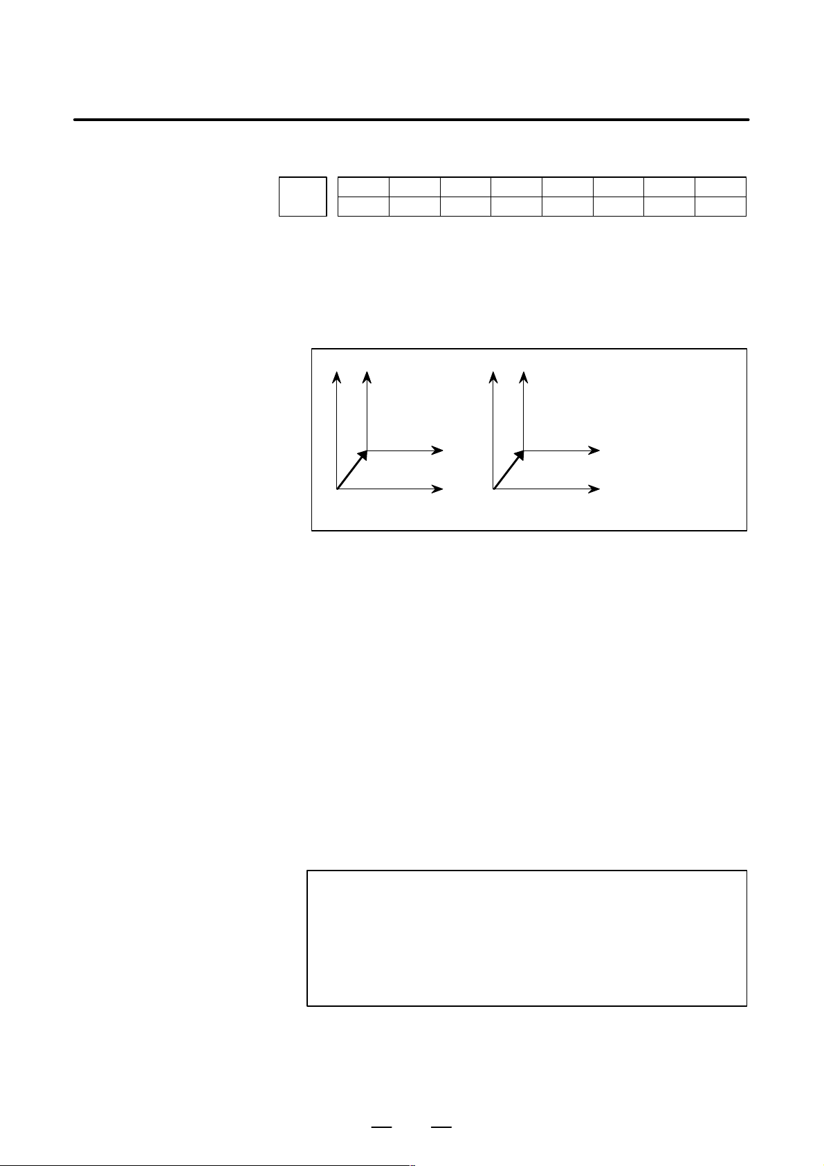
B–63610EN/01
4. DESCRIPTION OF PARAMETERS
#7
1202
#6 #5 #4
G52
#3
RLC
RLC
#2
G50
#1
EWS#0EWD
[Data type] Bit
EWD The shift direction of the workpiece coordinate system is:
0 : The direction specified by the external workpiece zero point offset
value
1 : In the opposite direction to that specified by the external workpiece
zero point offset value
X
XXX
EWD=0
Z
EXOFS
Z
EXOFS : External workpiece zero point offset value
EWD=1
–EXOFS
(Shifted workpiece
Z
coordinate system)
(Original workpiece
Z
coordinate system)
EWS Shift value of the workpiece coordinate system and external workpiece
zero point offset value are
0 : Stored in the separate memory areas.
1 : Stored in the same memory area, that is, the shift and the offset values
are the same.
G50 When the CNC has commands G54 to G59 specifying workpiece
coordinate systems (optional function), if the G50 command for setting a
coordinate system (or the G92 command in G command system B or C) is
specified,
0 : G50 is executed and no alarm is issued.
1 : G50 is not executed and a P/S alarm (No. 010) is issued.
RLC Local coordinate system is
0 : Not cancelled by reset
1 : Cancelled by reset
G52 In local coordinate system setting (G52), a cutter compensation vector is:
0 : Not considered.
1 : Considered.
NOTE
Select a local coordinate system setting operation when
cutter compensation is applied, and when two or more
blocks specifying no movement exist prior to the
specification of G52, or when G52 is specified after cutter
compensation mode is canceled without eliminating the
offset vector.
47
Page 54
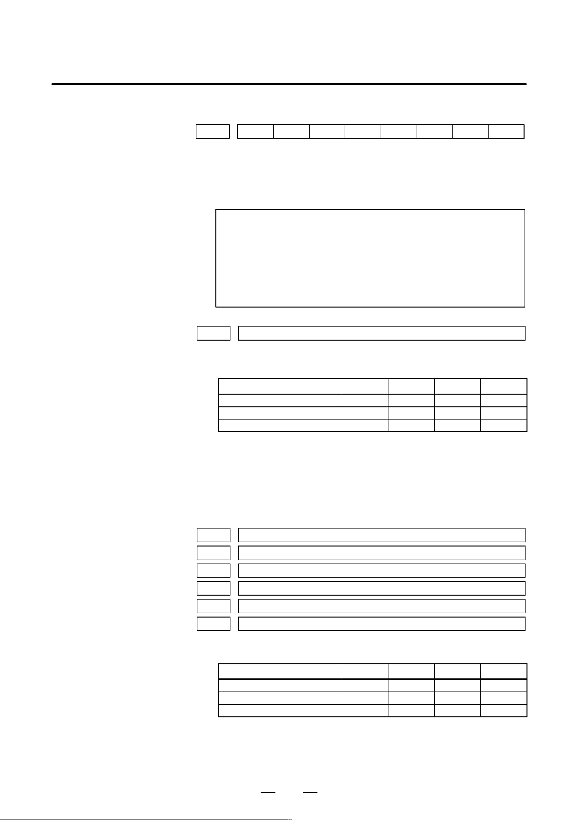
4. DESCRIPTION OF PARAMETERS
B–63610EN/01
1203
[Data type] Bit
EMC The extended external machine zero point shift function is:
0: Disabled.
1: Enabled.
NOTE
1 To use the extended external machine zero point shift
function, the external machine zero point shift function or the
external data input function is required.
2 When the extended machine zero point shift function is
enabled, the conventional external machine zero point shift
function is disabled.
1220 External workpiece zero point of fset value
[Data type] 2–word axis
[Unit of data]
Linear axis (input in mm) 0.01 0.001 0.0001
Linear axis (input in inches) 0.001 0.0001 0.00001 inch
Rotation axis 0.01 0.001 0.0001 deg
#7
Input increment IS–A IS–B IS–C Unit
#6 #5 #4 #3 #2 #1 #0
EMC
mm
[Valid data range] –99999999 to 99999999
This is one of the parameters that give the position of the origin of
workpiece coordinate system (G54 to G59). It gives an offset of the
workpiece origin common to all workpiece coordinate systems. In
general, the offset varies depending on the workpiece coordinate systems.
The value can be set from the PMC using the external data input function.
1221 Workpiece zero point offset value in workpiece coordinate system 1 (G54)
1222 Workpiece zero point of fset value in workpiece coordinate system 2(G55)
1223 Workpiece zero point of fset value in workpiece coordinate system 3(G56)
1224 Workpiece zero point offset value in workpiece coordinate system 4 (G57)
1225 Workpiece zero point offset value in workpiece coordinate system 5 (G58)
1226 Workpiece zero point offset value in workpiece coordinate system 6 (G59)
[Data type] 2–word axis
[Unit of data]
Input increment IS–A IS–B IS–C Unit
Linear axis (input in mm) 0.01 0.001 0.0001 mm
Linear axis (input in inches) 0.001 0.0001 0.00001 inch
Rotation axis 0.01 0.001 0.0001 deg
[Valid data range] –99999999 to 99999999
The workpiece zero point of fset values in workpiece coordinate systems 1
to 6 (G54 to G59) are set.
48
Page 55
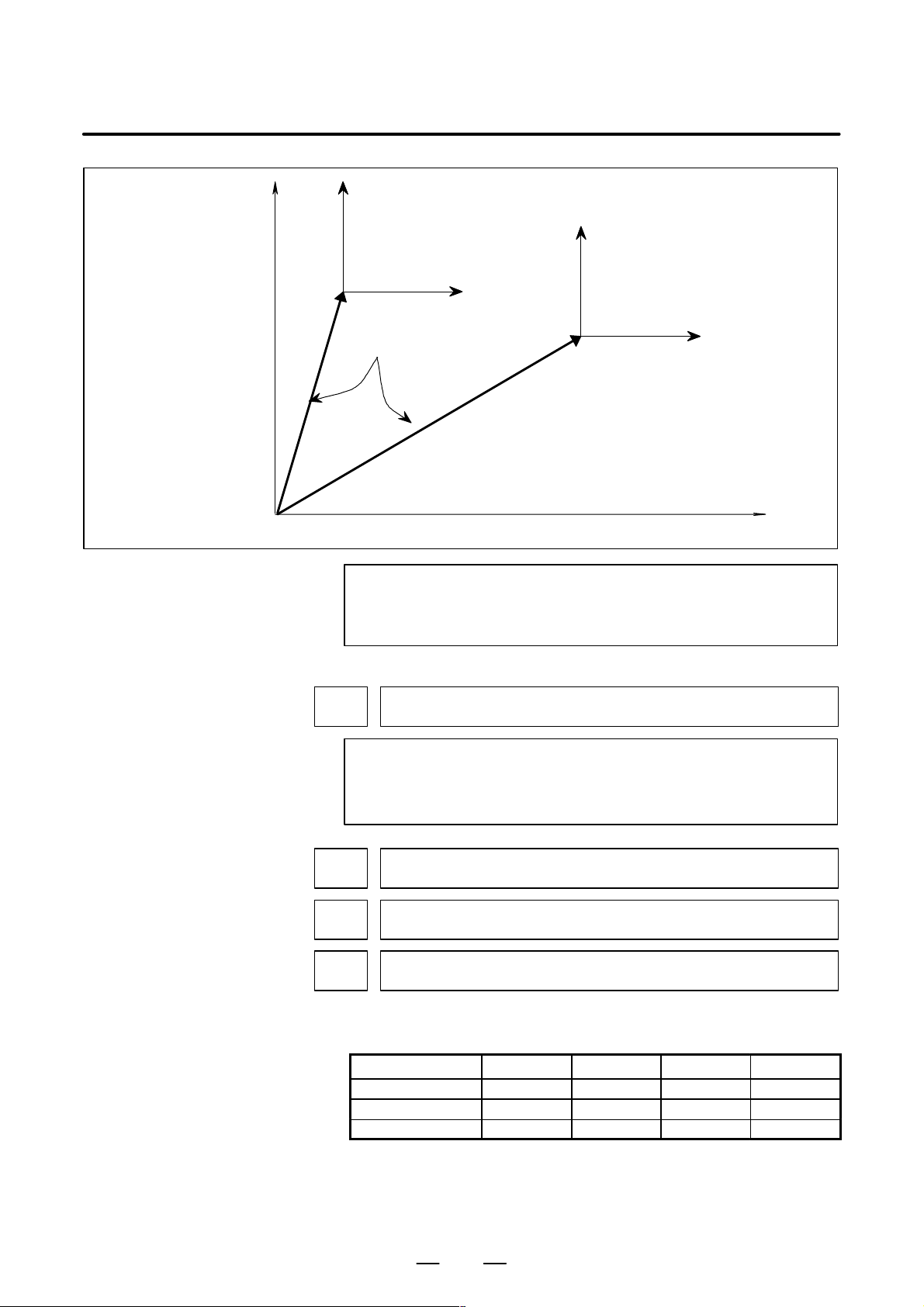
B–63610EN/01
4. DESCRIPTION OF PARAMETERS
Workpiece coordinate system 1 (G54)
Workpiece coordinate system 2 (G55)
Workpiece zero point offset
Origin of machine coordinate system
NOTE
The workpiece origin offset can also be set using the
workpiece coordinate system screen.
1240
Coordinate value of the reference position on each axis in the machine
coordinate system
NOTE
When this parameter is set, power must be turned off before
operation is continued.
1241
1242
1243
Coordinate value of the second reference position on each axis in the machine
coordinate system
Coordinate value of the third reference position on each axis in the machine coordinate system
Coordinate value of the fourth reference position on each axis in the machine
coordinate system
[Data type] 2–word axis
[Unit of data]
Increment system IS–A IS–B IS–C Unit
Millimeter machine 0.01 0.001 0.0001
Inch machine 0.001 0.0001 0.00001
Rotation axis 0.01 0.001 0.0001
[Valid data range] –99999999 to 99999999
Set the coordinate values of the first to fourth reference positions in the
machine coordinate system.
49
mm
inch
deg
Page 56
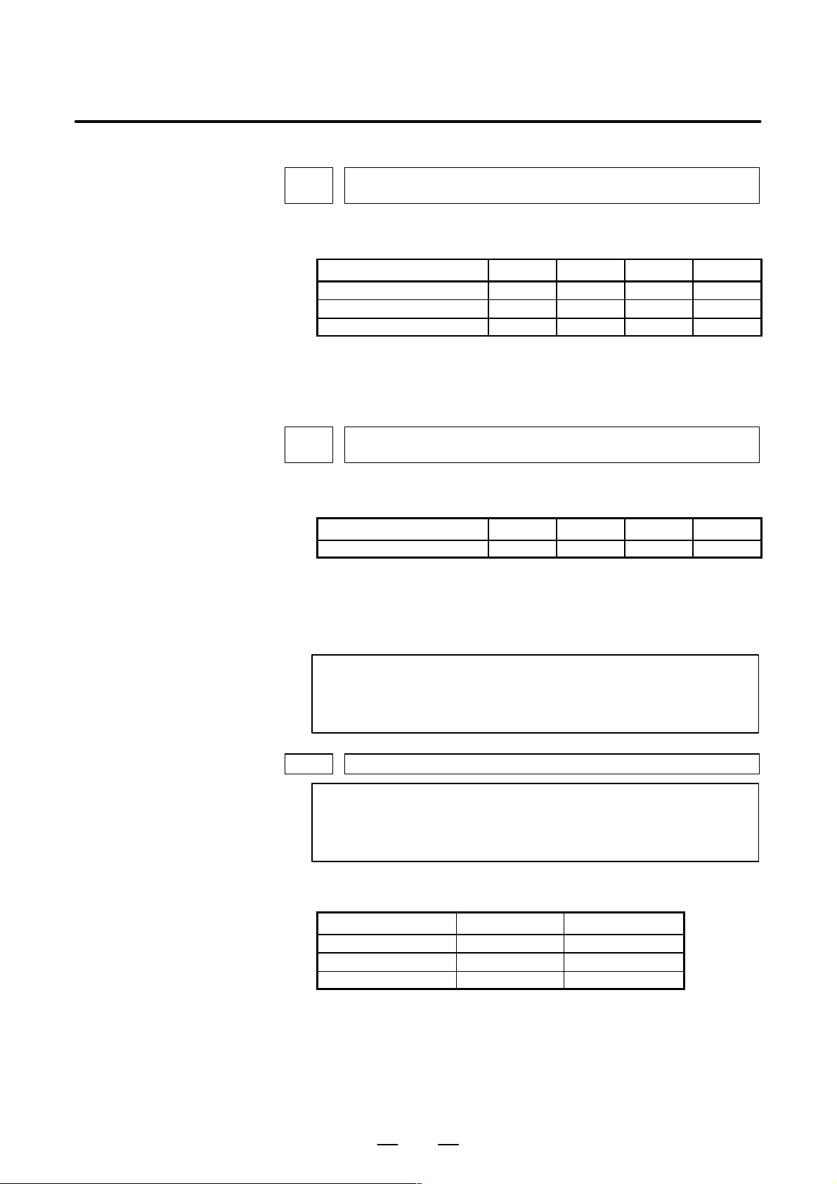
4. DESCRIPTION OF PARAMETERS
B–63610EN/01
1250
Coordinate value of the reference position used when automatic coordinate system setting is performed
[Data type] 2–word axis
[Unit of data]
Input increment IS–A IS–B IS–C Unit
Linear axis (input in mm) 0.01 0.001 0.0001 mm
Linear axis (input in inches) 0.001 0.0001 0.00001 inch
Rotation axis 0.01 0.001 0.0001 deg
[Valid data range] –99999999 to 99999999
Set the coordinate value of the reference position on each axis to be used
for setting a coordinate system automatically.
1251
Coordinate value of the reference position on each axis used for setting a coordinate system automatically when input is performed in inches
[Data type] 2–word axis
[Unit of data]
Incerment system IS–A IS–B IS–C Unit
Linear axis (input in inches) 0.001 0.0001 0.00001 inch
[Valid data range] –99999999 to 99999999
Set the coordinate value of the reference position on each axis to be used
for setting a coordinate system automatically when input is performed in
inches.
NOTE
This parameter is valid when ZPI in parameter 1201 is set to
1.
1260 Amount of a shift per one rotation of a rotation axis
NOTE
When this parameter is set, the power must be turned off
before operation is continued.
[Data type] 2–word axis
[Unit of data]
Increment system Unit of data Standard value
IS–A 0.01 deg 36000
IS–B 0.001 deg 360000
IS–C 0.0001 deg 3600000
[Valid data range] 1000 to 9999999
Set the amount of a shift per one rotaion of a rotaion axis.
50
Page 57

B–63610EN/01
4. DESCRIPTION OF PARAMETERS
1280
First address of the signal group used by the external machine zero point shift
extension
[Data type] Word
[Valid data range] 0 to 65535
Set the first address of the signal group used by the external machine zero
point shift extension. If 100 is specified, R0100 to R0115 can be used.
R0100
R0101
R0102
R0103
:
:
:
Shift amount of external machine zero point shift extension for
the first axis (LOW)
Shift amount of external machine zero point shift extension for
the first axis (HIGH)
Shift amount of external machine zero point shift extension for
the second axis (LOW)
Shift amount of external machine zero point shift extension for
the second axis (HIGH)
::
:
:
:
1290
[Data type] 2–word
[Unit of data]
R0114
R0115
Shift amount of external machine zero point shift extension for
the eighth axis (LOW)
Shift amount of external machine zero point shift extension for
the eighth axis (HIGH)
NOTE
1 This parameter is valid when bit 0 (EMC) of parameter No.
1203 is set to 1.
2 If the specified number is not present, the external machine
zero point shift extension is disabled.
3 A shift amount of the external machine zero point shift
extension can be written from the C executer or macro
executer.
Distance between two opposite tool posts in mirror image
Increment system IS–A IS–B IS–C Unit
Millimeter machine 0.01 0.001 0.0001 mm
Inch machine 0.001 0.0001 0.00001 inch
[Valid data range] 0 to 99999999
Set the distance between two opposite tool posts in mirror image.
51
Page 58

4. DESCRIPTION OF PARAMETERS
B–63610EN/01
4.13
P ARAMETERS OF STROKE CHECK
[Data type] Bit
1300
#7
BFA
BFA LZR LMS OUT
#6
LZR
#5
RL3
#4 #3 #2
LMS
#1 #0
OUT
OUT The area inside or outside of the stored stroke check 2 is set as an
inhibition area (setting by the parameters No.1322 and No.1323).
0: Inside
1: Outside
LMS The EXLM signal for switching stored stroke check
0: Disabled
1: Enabled
NOTE
Stored stroke check 1 supports two pairs of parameters for
setting the prohibited area. The stored stroke limit switching
signal is used to enable either of the prohibited areas set with
these parameter pairs.
(1) Prohibited area I: Parameters No.1320 and No.1321
(2) Prohibited area II: Parameters No.1326 and No.1327
RL3 Stored stroke check 3 release signal RLSOT3 is
0: Disabled
1: Enabled
LZR Checking of stored stroke check 1 during the time from power–on to the
manual position reference return
0: The stroke check 1 is checked.
1: The stroke check 1 is not checked
NOTE
When an absolute position detector is used and a reference
position is already set upon power–up, stored stroke limit
check 1 is started immediately after power–up, regardless of
the setting.
BFA When a command that exceeds a stored stroke check is issued
0: An alarm is generated after the stroke check is exceeded.
1: An alarm is generated before the stroke check is exceeded.
NOTE
The tool stops at a point up to F/7500 mm short of or ahead
of the boundary.
(F: Feedrate when the tool reaches the boundary (mm/min))
52
Page 59

B–63610EN/01
4. DESCRIPTION OF PARAMETERS
#7
1301
#6 #5 #4
OF1
OTS OF1 DLM
#3 #2 #1 #0
[Data type] Bit
DLM The stored stroke limit switching signal for each axial direction is:
0: Enabled.
1: Disabled.
OF1 If the tool is moved into the range allowed on the axis after an alarm is
raised by stored stroke check 1,
0: The alarm is not canceled before a reset is made.
1: The OT alarm is immediately canceled.
CAUTION
In the cases below, the automatic release function is
disabled. To release an alarm, a reset operation is required.
1 When a setting is made to issue an alarm before a stored
stroke limit is exceeded (bit 7 (BFA) of parameter No.
1300)
2 When an another overtravel alarm (such as stored stroke
check 2, stored stroke check 3, and interference check) is
already issued
3 When an overtravel alarm is already issued with the
high–precision contour control function or the chopping
function in the M series
DLM
OTS If a stored stroke limit alarm is raised by setting bit 7 (BFA) of parameter
No. 1300 to 1, the axial movement stops:
0: Before the boundary of stored stroke check.
1: On the boundary of stored stroke check.
CAUTION
To enable this parameter, the manual linear/circular
interpolation function is required. If this function is not
provided, this parameter setting is ignored.
#7
1310
#6 #5 #4 #3 #2 #1
OT3x#0OT2x
[Data type] Bit axis
OT2x Whether stored stroke check 2 is checked for each axis is set.
0: Stored stroke check 2 is not checked.
1: Stored stroke check 2 is checked.
OT3x Whether stored stroke check 3 is checked for each axis is set.
0: Stored stroke check 3 is not checked.
1: Stored stroke check 3 is checked.
OT2x
53
Page 60

4. DESCRIPTION OF PARAMETERS
1320 Coordinate value I of stored stroke check 1 in the positive direction on each axis
1321 Coordinate value I of stored stroke check 1 in the negative direction on each axis
[Data type] 2–word axis
[Unit of data]
[Valid data range] –99999999 to 99999999
B–63610EN/01
Increment system IS–A IS–B IS–C Unit
Millimeter machine 0.01 0.001 0.0001 mm
Inch machine 0.001 0.0001 0.00001 inch
Rotation axis 0.01 0.001 0.0001 deg
The coordinate values of stored stroke check 1 in the positive and negative
directions are setfor each axis in the machine coordinate system. The
outside area of the two checks set in the parameters is inhibited.
(Xp,Yp,Zp)
(Xm,Ym,Zm)
Set the machine coordinates of the
boundaries in the positive direction
(Xp, Yp, and Zp) using parameter No.
1320, and those of the boundaries in
the negative direction (Xm, Ym, and
Zm) using parameter No. 1321. The
prohibited area thus becomes the
hatched area in the figure on the left.
NOTE
1 For axes with diameter specification, a diameter value must
be set.
2 When the parameters are set as follows, the stroke becomes
infinite:
parameter 1320 < parameter 1321
For movement along the axis for which infinite stroke is set,
only increment commands are available. (The stored stroke
limit switching signal also becomes invalid.) If an absolute
command is issued for this axis, the absolute register may
overflow, and normal movement will not result.
3 The prohibited area specified with these parameters is
invalid if bit 2 (LMS) of parameter No. 1300 is set to 1 and
stored stroke limit switching signal EXLM is set to 1. In such
a case, the settings of parameters No. 1326 and 1327 are
used, instead.
54
Page 61

B–63610EN/01
1322 Coordinate value of stored stroke check 2 in the positive direction on each axis
1323 Coordinate value of stored stroke check 2 in the negative direction on each axis
[Data type] 2–word axis
[Unit of data]
Increment system IS–A IS–B IS–C Unit
Millimeter machine 0.01 0.001 0.0001 mm
Inch machine 0.001 0.0001 0.00001 inch
Rotation axis 0.01 0.001 0.0001 deg
[Valid data range] –99999999 to 99999999
Set the coordinate values of stored stroke check 2 in the positive and
negative directions foreach axis in the machine coordinate system. OUT,
#0 of parameter 1300, sets either the area outside of the area inside
specified by two checks are the inhibition area.
(1) When the prohibited area is inside the boundaries (OUT = 0)
(Xm,Ym,Zm)
(2) When the prohibited area is outside
the boundaries (OUT = 1)
4. DESCRIPTION OF PARAMETERS
(Xp,Yp,Zp)
(Xp,Yp,Zp)
Set the machine coordinates of the
boundaries in the positive direction
(Xp, Yp, and Zp) using parameter
No. 1322, and those of the boundaries in the negative direction (Xm,
Ym, and Zm) using parameter No.
1323. The prohibited area thus
becomes the hatched area in the
figure on the left.
(Xm,Ym,Zm)
NOTE
For axes with diameter specification, a diameter value must
be set.
55
Page 62
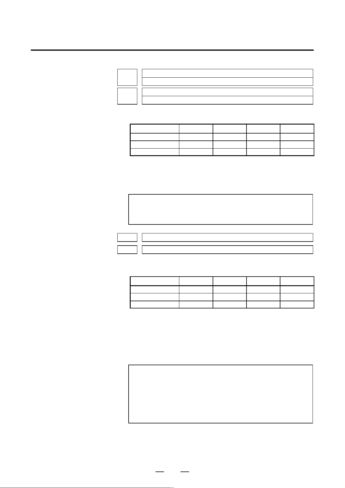
4. DESCRIPTION OF PARAMETERS
B–63610EN/01
1324
1325
Coordinate value of stored stroke check 3 in the positive direction on each axis
Coordinate value of stored stroke check 3 in the positive direction on each axis
[Data type] 2–word axis
[Unit of data]
Increment system IS–A IS–B IS–C Unit
Millimeter machine 0.01 0.001 0.0001 mm
Inch machine 0.001 0.0001 0.00001 inch
Rotation axis 0.01 0.001 0.0001 deg
[Valid data range] –99999999 to 99999999
Set the coordinate values of stored stroke check 3 in the positive and
negative directions foreach axis in the machine coordinate system. The
area inside the checks set in the parameter is inhibited.
NOTE
Specify diameters for any axis for which diameter
programming is specified.
1326 Coordinate value II of stored stroke check 1 in the positive direction on each axis
1327 Coordinate value II of stored stroke check 1 in the negative direction on each axis
[Data type] 2–word axis
[Unit of data]
Increment system IS–A IS–B IS–C Unit
Millimeter machine 0.01 0.001 0.0001 mm
Inch machine 0.001 0.0001 0.00001 inch
Rotation axis 0.01 0.001 0.0001 deg
[Valid data range] –99999999 to 99999999
Set the coordinate values of stored stroke check 1 in the positive and
negative directions foreach axis in the machine coordinate system.
When stroke check switching signal EXLM is ON, stroke check are
checked with parameters 1326 and 1327, not with parameters 1320 and
1321. The area outside that set by parameters 1326 and 1327 is inhibited.
NOTE
1 Specify diameter values for any axes for which diameter
programming is specified.
2 These parameters are invalid if bit 2 (LMS) of parameter No.
1300 is set to 0, or if stored stroke limit switching signal
EXLM is set to 0. In such a case, the settings of parameters
No. 1320 and 1321 are used, instead.
56
Page 63
B–63610EN/01
4.14
P ARAMETERS OF THE CHUCK AND TAILSTOCK BARRIER (T SERIES)
[Valid data range] 0 or 1
1330
[Data type] Byte
0: Chuck which holds a workpiece on the inner surface
1: Chuck which holds a workpiece on the outer surface
4. DESCRIPTION OF PARAMETERS
Profile of a chuck
1331
1332
1333
1334
1335
1336
[Data type] 2–word
[Unit of data]
Dimensions of the claw of a chuck (L)
Dimensions of the claw of a chuck (W)
Dimensions of the part of a claw at which a workpiece is held (L1)
Dimensions of the part of a claw at which a workpiece is held (W1)
X coordinate of a chuck (CX)
ZX coordinate of a chuck (CZ)
Increment system IS–B IS–C Unit
Millimeter input 0.001 0.0001 mm
Inch input 0.0001 0.00001 inch
[Valid range] No.1331 to No.1334: 0 to 99999999
No.1335 to No.1336: –99999999 to 99999999
Specify the profile of a chuck.
57
Page 64

4. DESCRIPTION OF PARAMETERS
B–63610EN/01
Chuck which holds a workpiece on the outer surface
(TY= 1)
L
L1
W
W1
X
A
CX
CZ
Zero point of the
workpiece
coodinate system
Symbol
Ty Profile of a chuck (0: Chuck which holds a workpiece on the inner
CX X coordinate of a chuck
CZ Z coordinate of a chuck
L
W
surface, 1: Chuck which holdsa workpiece on the outer surface)
L Dimensions of the claw of a chuck
W Dimensions of the claw of a chuck (radius input)
Dimensions of the part of a claw at which a workpiece is held
1
Dimensions of the part of a claw at which a workpiece is held (ra-
1
dius input)
Chuck which holds a workpiece on the inner surface
(TY= 0)
L
A
W1
W
L1
Z
CZ
Decription
X
Zero point of the
workpiece
coodinate system
CX
Z
TY Specifies the profile of a chuck. When TY is set to 0, the chuck holding a
workpiece on theinner surface is specified. When TY is set to 1, the chuck
holding a workpiece on the outer surface is specified. The profile of the
chuck is assumed to be symmetrical with respect to the z–axis.
CX, and CZ Specify the position (point A) of a chuck with the coordinates of the
workpiece coordinate system. In this case, do not use the coordinates of
the machine coordinate system.
NOTE
Specifying t he coordinates wit h a diameter or radi us d epends
on whether the correspondingaxis conforms to diameter or
radius specification. When the axis conforms to diameter
specification, spcify the coordinates with a diameter.
L, L1, W and W1 Define the profile of a chuck.
NOTE
Always specify W and W1 with radiuses. Specify L and L1
with radiuses when the Z–axis conforms to radius
specification.
58
Page 65
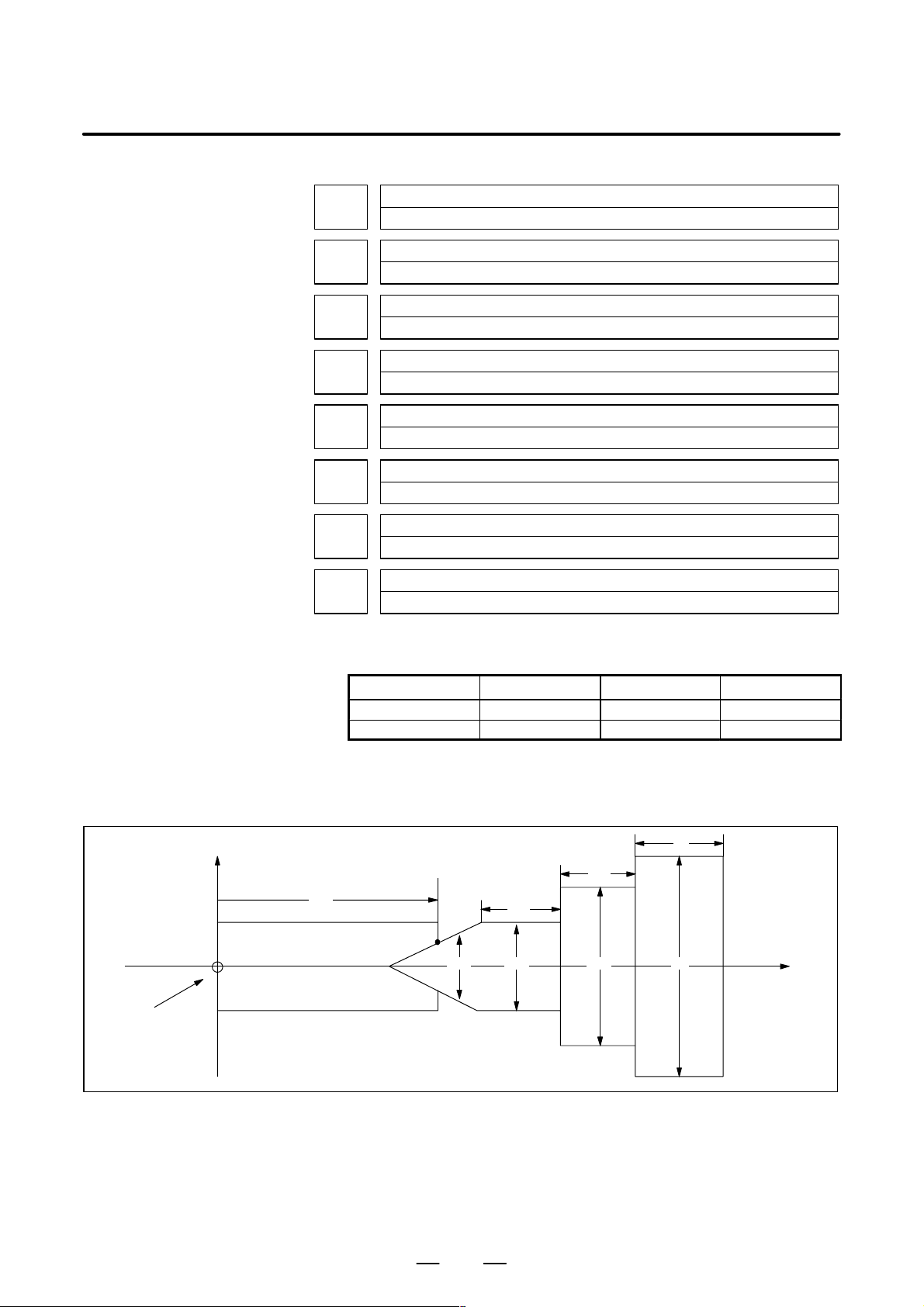
B–63610EN/01
4. DESCRIPTION OF PARAMETERS
1341
1342
1343
1344
1345
1346
1347
1348
[Data type] 2–words
Length of a tailstock (L)
Diameter of a tailstock (D)
Length of a tailstock (L1)
Diameter of a tailstock (D1)
Length of a tailstock (D1)
Diameter of a tailstock (D2)
Diameter of the hole of a tailstock (D3)
Z coordinate of a tailstock (TZ)
Zero point of
the workpiece
coordinate
system
[Unit of data]
Increment system IS–B IS–C Unit
Millimeter input 0.001 0.0001 mm
Inch input 0.0001 0.00001 inch
[Valid range] No.1341 to No.1347: 0 to 99999999
No.1348: –99999999 to 99999999
Specify the profile of a tailstock.
X
Workpiece
TZ
B
D3
L2
D2 D1 D
L
L1
Z
59
Page 66

4. DESCRIPTION OF PARAMETERS
TZ: Specifies the position (point B) of a tailstock with the Z–axis coordinate
B–63610EN/01
Symbol Description
TZ Z–axis coordinate of a tailstock
L Length of a tailstock
D Diameter of a tailstock (diameter input)
L1 Length of a tailstock (1)
D1 Diameter of a tailstock (1) (diameter input)
L2 Length of a tailstock (2)
D2 Diameter of a tailstock (2) (diameter input)
D3 Diameter of the hole of a tailstock (diameter input)
of the workpiece coordinate system. In this case, do not use the coordinate
of the machine coordinate system. The profile of a tailstock is assumed to
be symmetrical with respect to the Z–axis.
NOTE
Specifying the position of a tailstock with a radius or diameter
depends on whether the Z–axis conforms to radius or
diameter specification.
L, L1, L2, D, D1, D2, and D3:
Define the profile of a tailstock.
NOTE
Always specify D, D1, D2, and D3 with diameters. Specify L,
L1, and L2 with radiuses if the Z–axis conforms to radius
specification.
60
Page 67

B–63610EN/01
4.15
4. DESCRIPTION OF PARAMETERS
P ARAMETERS OF FEEDRATE
[Data type] Bit
#7
1401
#6
RDR
RDR
#5
TDR
TDR
#4
RF0
RF0
#3 #2
JZR
#1
LRP
LRP
#0
RPD
RPD
RPD Manual rapid traverse during the period from power–on time to the
completion of the reference position return.
0: Disabled (Jog feed is performed.)
1: Enabled
LRP Positioning (G00)
0: Positioning is performed with non–linear type positioning so that the
tool moves along each axis independently at rapid traverse.
1: Positioning is performed with linear interpolation so that the tool
moves in a straight line.
JZR The manual reference position return at JOG feedrate
0: Not performed
1: Performed
RF0 When cutting feedrate override is 0% during rapid traverse,
0: The machine tool does not stop moving.
1: The machine tool stops moving.
TDR Dry run during threading or tapping (tapping cycle G74 or G84, rigid
tapping)
0: Enabled
1: Disabled
RDR Dry run for rapid traverse command
0: Disabled
1: Enabled
#7
1402
#6 #5 #4
JRV
#3 #2 #1
JOV
JOV
[Data type] Bit
NPC The feed per rotation command is:
0: Ineffective when a position coder is not provided.
1: Effective even when a position coder is not provided (because the
CNC converts it to the feed per minute command from F command S
command).
NOTE
To use a position coder, set this parameter to 0. While
this parameter is set to 1, threading cannot be performed
even if a position coder is provided.
#0
NPC
NPC
JOV Job override is:
0: Enabled
1: Disabled (tied to 100%)
61
Page 68

4. DESCRIPTION OF PARAMETERS
JRV Manual continuous feed (jog feed)
B–63610EN/01
0: Jog feed is performed at feed per minute.
1: Jog feed is performed at feed per rotation.
NOTE
Specify a feedrate in parameter No.1423.
1403
#7
RTV
#6 #5 #4 #3 #2 #1 #0
NOTE
When this parameter is set, the power must be turned off
before operation is continued.
[Data type] Bit
MIF Cutting feedrates at feed per minute is specified by F commands
0: In units of 1 mm/min for millimeter machines or 0.01 inches/min for
inch machines.
1: In unit of 0.001 mm/min for millimeter machines or 0.00001
inches/min for inch machines.
NOTE
M series are not equipped with this parameter. Cutting
feedrates are specified by F commands in units of 0.001
mm/min for millimeter machines or 0.00001 inches/min for
inch machines.
MIF
RTV Override while the tool is retracting in threading
0 : Override is effective.
1 : Override is not effective.
1404
#7
FC0
#6 #5
EDR
EDR
#4 #3
FRV
FRV
#2
F8A
F8A
DLF
DLF
[Data type] Bit
HFC The feedrate for helical interpolation is:
0: Clamped so that the feedrates along an arc and linear axis do not
exceed the maximum cutting feedrate specified by parameter
(No.1422 or 1430).
1: Clamped so that the composite feedrate along an arc and linear axis does
not exceed the maximum cutting feedrate specified by parameter
(No.1422).
DLF After a reference potition is set, manual reference position return
performed at:
0 : Rapid traverse rate (parameter No.1420)
1 : Manual rapid traverse rate (parameter No.1424)
#1
#0
HFC
62
Page 69
B–63610EN/01
<For T series>
F8A Valid data range for an F command in feed–per–minute mode
<For M series>
F8A Valid data range for an F command with a decimal point in feed–per
4. DESCRIPTION OF PARAMETERS
NOTE
This parameter selects a feedrate for reference position
return performed without dogs. This parameter also selects
a feedrate when manual reference position return is
performed according to bit 7 (SJZ) of parameter No.0002
using rapid traverse without deceleration dogs after a
reference position is set.
0: Range specified with bit 0 (MIF) of parameter No.1403
1:
Increment system Units IS–A, IS–B IS–C
Millimeter input mm/min 0.001 to 240000. 0.001 to 100000.
Inch input
Rotation axis deg/min 1 to 240000. 1 to 100000.
inch/min 0.00001 to 9600. 0.00001 to 4000.
minute mode
0:
Increment system Units IS–A, IS–B IS–C
Millimeter input mm/min 0.001 to 99999.999.
Inch input inch/min 0.00001 to 999.99999.
Rotation axis (mm) deg/min 1 to 240000. 1 to 100000.
Rotation axis (inch) deg/min 1 to 9600. 1 to 4000.
1:
Increment system Units IS–A, IS–B IS–C
Millimeter input mm/min 0.001 to 240000. 0.001 to 100000.
Inch input inch/min 0.00001 to 9600. 0.00001 to 4000.
Rotation axis deg/min 1 to 240000. 1 to 100000.
FRV For inch input, the valid range of the feedrate specified for feed per
revolution is:
0 : Standard range. (F0.000001 to 9.999999 inches per revolution)
1 : Extended to F50.0 inches per revolution. (F0.000001 to 50.000000
inches per revolution)
EDR The external deceleration speed in liner interpolation type positioning is
set in:
0: Parameter No. 1426.
1: Parameter No. 1427, for the first axis.
FC0 Specifies the behavior of the machine tool when a block (G01, G02, G03,
etc.) containing a feedrate command (F command) that is 0 is issued
during automatic operation, as follows:
0: A P/S alarm (No.011) is displayed, and the block is not executed.
1: No alarm is displayed, and the block is executed.
63
Page 70

4. DESCRIPTION OF PARAMETERS
I
I
Unitofdat
I
Unitofdat
B–63610EN/01
#7
1405
#6 #5 #4 #3 #2 #1
[Data type] Bit
F1U Specifies the units of the data for the parameters that set the feedrates of
the F1–digit feed commands (parameter Nos. 1451 to 1459).
ncrementsystem
Millimeter machine 0.1 mm/min 1 mm/min
Inch machine 0.001 inch/min 0.1 inch/min
Rotation axis 0.1 deg/min 1 deg/min
When F1U is 0 When F1U is 1
Units of data
FD3 The number of significant digits of the fractional part in the feedrate
command (F command) for feed per revolution is:
0 : Up to two decimal positions (three decimal positions for inch input).
1 : Up to three decimal positions (four decimal positions for inch input).
#7
1408
#6 #5 #4 #3 #2 #1 #0
[Data type] Bit axis type
RFD The feedrate about a rotation axis is controlled:
0: In the usual method.
1: By converting the rotation speed about the rotation axis into the travel
speed on the circumference of a virtual circle.
Set the radius of the virtual circle in parameter No. 1465.
FD3
#0
F1U
RFD
1410 Dry run rate
[Data type] Word
[Unit of data]
[Valid data range]
1411
[Data type] Word
[Unit of data]
[Valid data range]
ncrementsystem
Millimeter machine 1 mm/min 6 to 15000 6 to 12000
Inch machine 0.1 inch/min 6 to 6000 6 to 4800
a
Valid data range
IS-A, IS-B IS-C
Set the dry run rate when the manual feedrate is overridden by 100%.
Cutting feedrate in the automatic mode at power–on
Setting entry is acceptable.
ncrementsystem
Millimeter machine 1 mm/min 6 to 32767 6 to 32767
Inch machine 0.1 inch/min 6 to 32767 6 to 32767
a
Valid data range
IS-A, IS-B IS-C
64
Page 71
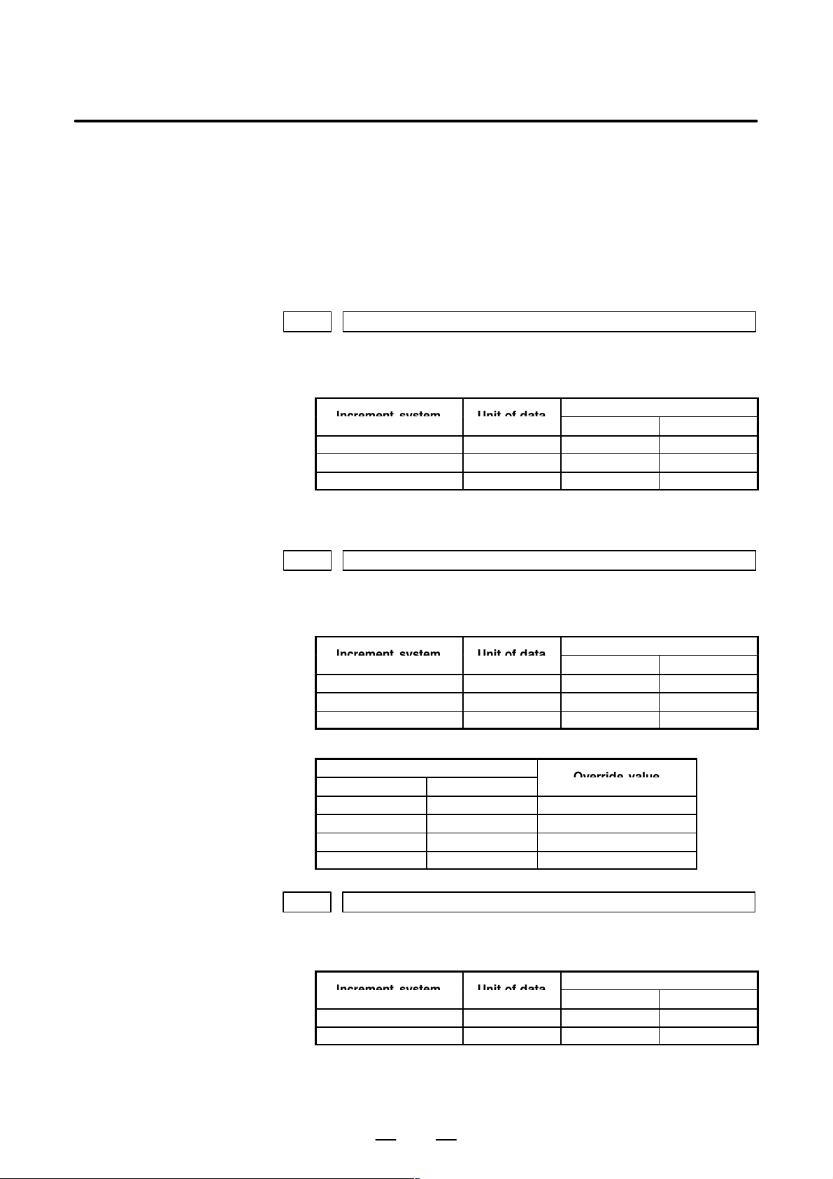
B–63610EN/01
I
Unitofdat
I
Unitofdat
O
I
Unitofdat
1420 Rapid traverse rate for each axis
[Data type] 2–word axis
[Unit of data]
[Valid data range]
4. DESCRIPTION OF PARAMETERS
When the machine requires little change in cutting feedrate during
cutting, a cutting feedrate can be specified in the parameter. This
eliminates the need to specify a cutting feedrate (F command) in the NC
program.
The cutting feedrate set by this parameter is valid after the CNC is placed
in the clear state by power–up or a reset until a feedrate is specified by a
program command (F command). After a feedrate is specified by the F
command, the feedrate becomes valid.
ncrementsystem
Millimeter machine 1 mm/min 30 to 240000 6 to 100000
Inch machine 0.1 inch/min 30 to 96000 6 to 48000
Rotation axis 1 deg/min 30 to 240000 6 to 100000
a
Valid data range
IS-A, IS-B IS-C
Set the rapid traverse rate when the rapid traverse override is 100% for
each axis.
1421 F0 rate of rapid traverse override for each axis
[Data type] Word axis
[Unit of data]
[Valid data range]
1422 Maximum cutting feedrate for all axes
[Data type] 2–word
[Unit of data]
[Valid data range]
ncrementsystem
Millimeter machine 1 mm/min 30 to 15000 30 to 12000
Inch machine 0.1 inch/min 30 to 6000 30 to 4800
Rotaion axis 1 deg/min 30 to 15000 30 to 12000
a
Valid data range
IS-A, IS-B IS-C
Set the F0 rate of the rapid traverse override for each axis.
Rapid traverse override signal
ROV2 ROV1
0 0 100%
0 1 50%
1 0 25%
1 1 F0
verridevalue
F0: Parameter 1421
ncrementsystem
Millimeter machine 1 mm/min 6 to 240000 6 to 100000
Inch machine 0.1 inch/min 6 to 96000 6 to 48000
a
Valid data range
IS-A, IS-B IS-C
Specify the maximum cutting feedrate.
A feedrate in the tangential direction is clamped in cutting feed so that it
does not exceed the feedrate specified in this parameter.
65
Page 72
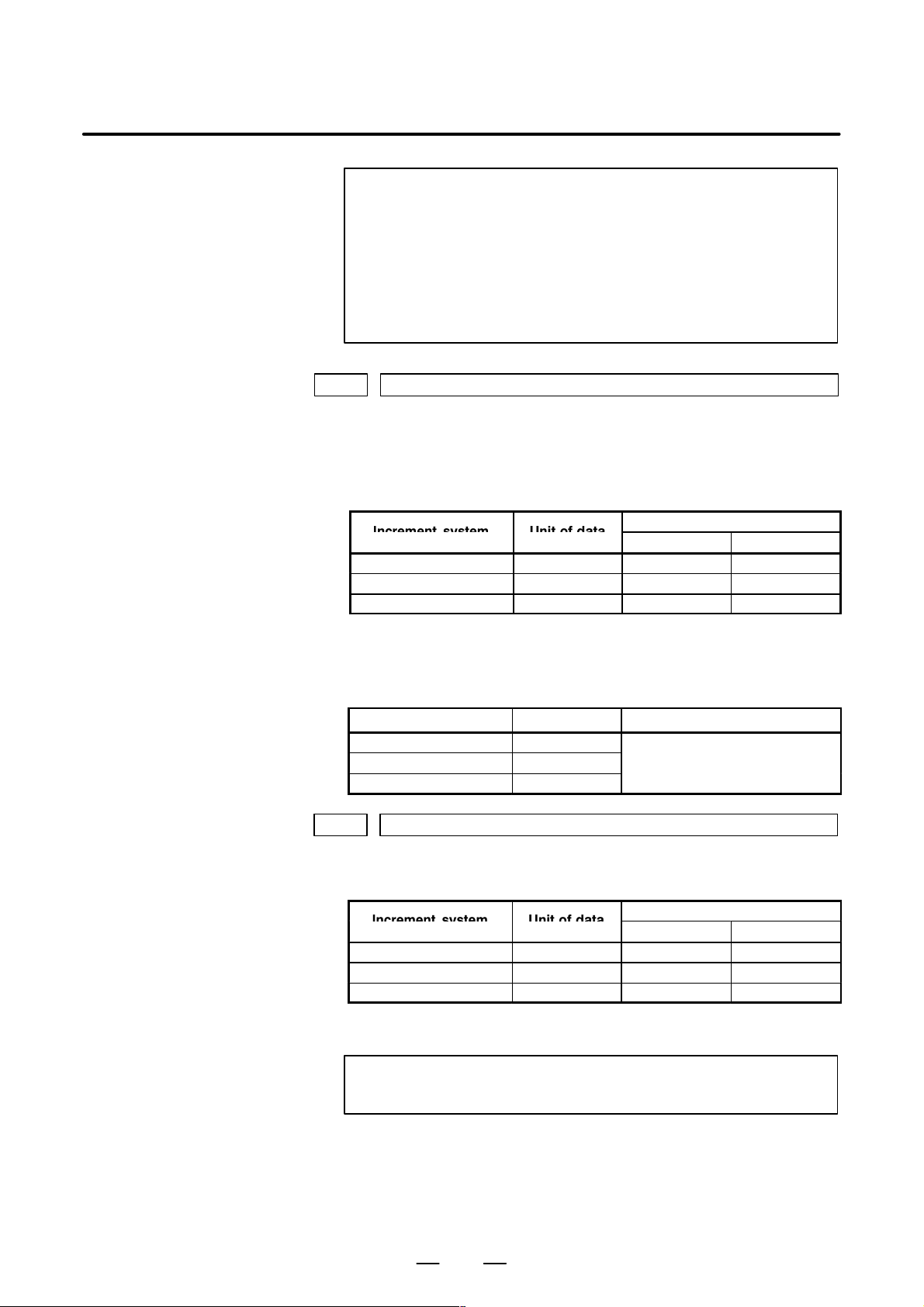
4. DESCRIPTION OF PARAMETERS
I
Unitofdat
I
Unitofdat
1423 Feedrate in manual continuous feed (jog feed) for each axis
[Data type] Word axis
[Unit of data, valid range]
B–63610EN/01
NOTE
1 A maximum cutting feedrate can be specified for each axis
only during linear interpolation and circular interpolation by
using parameter No. 1430.
2 Even when parameter No. 1430 is used, clamping to a
maximum cutting feedrate based on parameter No. 1422 is
enabled during polar coordinate interpolation, cylindrical
interpolation, and involute interpolation (M series).
(1) In M series, or in T series when JRV, bit 4 of parameter No.1402, is set
to 0 (feed per minute), specify a jog feedrate at feed per minute with an
override of 100%.
ncrementsystem
Millimeter machine 1 mm/min 6 to 15000 6 to 12000
Inch machine 0.1 inch/min 6 to 6000 6 to 4800
Rotaiton axis 1 deg/min 6 to 15000 6 to 12000
a
Valid data range
IS-A, IS-B IS-C
(2) When JR V , bit 4 of parameter No.1402, is set to 1 (feed per revolution)
[Unit of data, valid range]
Increment system Unit of data Valid data range
Millimeter machine 0.01 mm/rev
Inch machine 0.001 mm/rev
Rotation axis 0.01 deg/rev
1424 Manual rapid traverse rate for each axis
[Data type] 2–word axis
[Unit of data]
[Valid data range]
Millimeter machine 1 mm/min 30 to 240000 30 to 100000
Inch machine 0.1 inch/min 30 to 96000ă 30 to 48000
Rotation axis 1 deg/min 30 to 240000 30 to 100000
Set the rate of manual rapid traverse when the rapid traverse override is
100% for each axis.
NOTE
in T series, specify a jog feedarate (feed per revolution) under an
override of 100%.
0 to 32767
ncrementsystem
a
Valid data range
IS-A, IS-B IS-C
If 0 is set, the rate set in parameter 1420 is assumed.
66
Page 73
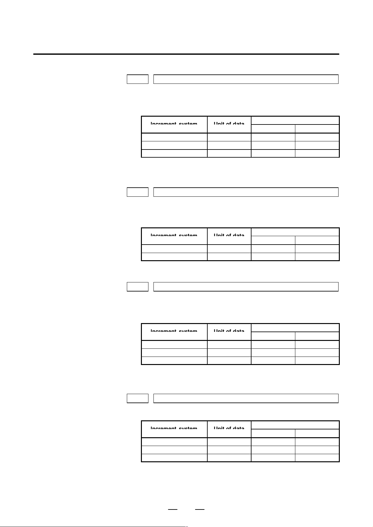
B–63610EN/01
I
Unitofdat
I
Unitofdat
I
Unitofdat
I
Unitofdat
1425 FL rate of the reference position return for each axis
[Data type] Word axis
[Unit of data]
[Valid data range]
1426 External deceleration rate of cutting feed
[Data type] Word axis
[Unit of data]
[Valid data range]
4. DESCRIPTION OF PARAMETERS
ncrementsystem
Millimeter machine 1 mm/min 6 to 15000 6 to 12000
Inch machine 0.1 inch/min 6 to 6000 6 to 4800
Rotaion axis 1 deg/min 6 to 15000 6 to 12000
a
Valid data range
IS-A, IS-B IS-C
Set feedrate (FL rate) after deceleration when the reference position return
is performed for each axis.
ncrementsystem
Millimeter machine 1 mm/min 6 to 15000 6 to 12000
Inch machine 0.1 inch/min 6 to 6000 6 to 4800
a
Valid data range
IS-A, IS-B IS-C
1427 External deceleration rate of rapid traverse for each axis
[Data type] Word axis
[Unit of data]
[Valid data range]
1430 Maximum cutting feedrate for each axis
[Data type] 2–word axis
Set the external deceleration rate of cutting feed.
ncrementsystem
Millimeter machine 1 mm/min 6 to 15000 6 to 12000
Inch machine 0.1 inch/min 6 to 6000 6 to 4800
Rotaion axis 1 deg/min 6 to 15000 6 to 12000
a
Valid data range
IS-A, IS-B IS-C
Set the external deceleration rate of rapid traverse for each axis.
ncrementsystem
Millimeter machine 1 mm/min 6 to 240000 6 to 100000
Inch machine 0.1 inch/min 6 to 96000 6 to 48000
Rotaion axis 1 deg/min 6 to 240000 6 to 100000
a
Valid data range
IS-A, IS-B IS-C
Specify the maximum cutting feedrate for each axis.
A feedrate for each axis is clamped in cutting feed so that it does not
exceed the maximum feedrate specified for each axis.
67
Page 74
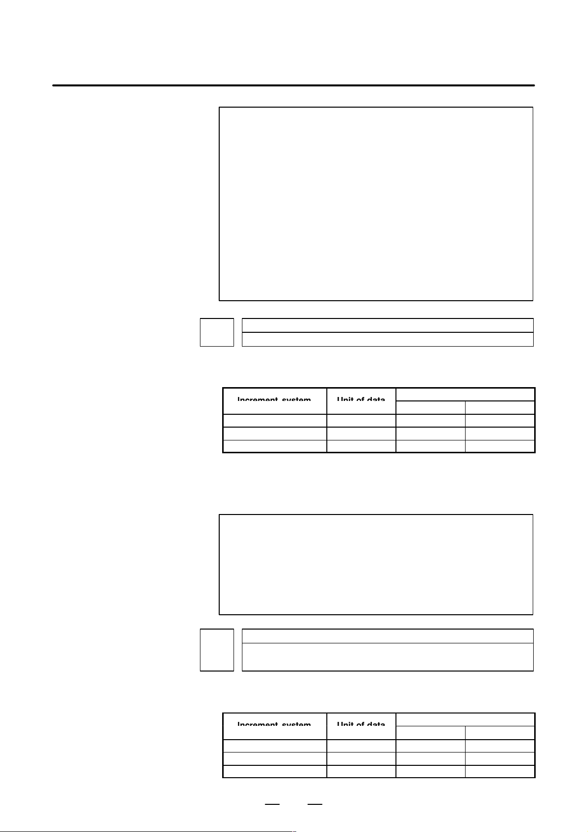
4. DESCRIPTION OF PARAMETERS
I
Unitofdat
I
Unitofdat
B–63610EN/01
NOTE
1 This parameter is valid only during linear interpolation and
circular interpolation. Even when this parameter is set,
clamping to a maximum cutting feedrate based on
parameter No. 1422 is enabled during polar coordinate
interpolation, cylindrical interpolation, and involute
interpolation (M series).
2 When this parameter is set to 0 for all axes, clamping to a
maximum cutting feedrate based on parameter No. 1422 is
enabled.
This means that if a value other than 0 is set for any of the axes
with this parameter, clamping to a maximum cutting feedrate
is performed for all axes during linear interpolation or circular
interpolation according to this parameter.
1431
[Data type] 2–words
[Unit of data, valid range]
ncrementsystem
Millimeter machine 1 mm/min 0 to 240000 0 to 100000
Inch machine 0.1 inch/min 0 to 96000 0 to 48000
Rotaion axis 1 deg/min 0 to 240000 0 to 100000
Specify the maximum cutting feedrate for all axes in the look–ahead
control mode.
A feedrate in the tangential direction is clamped in cutting feed so that it
does not exceed the feedrate specified in this parameter.
NOTE
1 To specify the maximum cutting feedrate for each axis, use
parameter No.1432 instead.
2 In a mode other than the look–ahead mode, the maximum
cutting feedrate specified in parameter No.1422 or No.1430
is applied and the feedrate is clamped at the maximum
feedrate.
Maximum cutting feedrate for all axes in the look–ahead control mode
a
Valid data range
IS-A, IS-B IS-C
1432
[Data type] 2–word axis
[Unit of data, valid range]
ncrementsystem
Millimeter machine 1 mm/min 0 to 240000 0 to 100000
Inch machine 0.1 inch/min 0 to 96000 0 to 48000
Rotaion axis 1 deg/min 0 to 240000 0 to 100000
Maximum cutting feedrate for each axis in the AI look–ahead control mode or look–
ahead control mode
a
IS-A, IS-B IS-C
Valid data range
68
Page 75

B–63610EN/01
4. DESCRIPTION OF PARAMETERS
Specify the maximum cutting feedrate for each axis in the AI look–ahead
control mode or look–ahead control mode.
A feedrate for each axis is clamped during cutting feed so that it does not
exceed the maximum cutting feedrate specified for each axis.
NOTE
1 This parameter is effective only in linear and circular
interpolation. In cylindrical interpolation, the maximum
feedrate for all axes specified in parameter No.1431 is
effective.
2 If a setting for each axis is 0, the maximum feedrate specified
in parameter No.1431 is applied to all axes and the feedrate
is clamped at the maximum feedrate.
3 In a mode other than the AI look–ahead control mode or
look–ahead mode, the maximum cutting feedrate specified
in parameter No.1422 or No.1430 is applied and the
feedrate is clamped at the maximum feedrate.
1450
[Data type] Byte
[Valid data range] 1 to 127
Set the constant that determines the change in feedrate as the manual pulse
generator is rotated one graduation during F1-digit feed.
∆
In the above equation, set n. That is, the number of revolutions of the
manual pulse generator, required to reach feedrate Fmaxi is obtained.
Fmaxi refers to the upper limit of the feedrate for an F1-digit feed
command, and set it in parameter 1460 or 1461.
Fmax1: Upper limit of the feedrate for F1 to F4 (parameter 1460)
Fmax2: Upper limit of the feedrate for F5 to F9 (parameter 1461)
Change of feedrate for one graduation on the manual pulse generator during F1
digit feed
Fmaxi
F +
100n
(where, i=1 or 2)
69
Page 76

4. DESCRIPTION OF PARAMETERS
B–63610EN/01
1451
1452
1453
1454
1455
1456
1457
1458
1459
Setting entry is acceptable.
[Data type] 2–word
Feedrate for F1 digit command F1
Feedrate for F1 digit command F2
Feedrate for F1 digit command F3
Feedrate for F1 digit command F4
Feedrate for F1 digit command F5
Feedrate for F1 digit command F6
Feedrate for F1 digit command F7
Feedrate for F1 digit command F8
Feedrate for F1 digit command F9
[Unit of data, valid range]
(1) When the F1U parameter (bit 0 of parameter No.1405) is 0
Increment system Units of data
Millimeter machine 0.1 mm/min 6 to 150000 6 to 120000
Inch machine 0.01 inch/min 6 to 60000 6 to 48000
Rotation axis 0.1 deg/min 6 to 150000 6 to 120000
(2) When the F1U parameter (bit 0 of parameter No.1405) is 1
Increment system Units of data
Millimeter machine 1 mm/min 6 to 15000 6 to 12000
Inch machine 0.1 inch/min 6 to 6000 6 to 4800
Rotation axis 1 deg/min 6 to 15000 6 to 12000
These parameters set the feedrates for 1–digit feed commands F1 to F9.
When an 1–digit feed command is specified, and the feedrate is changed
by turning the manual pulse generator, the parameter–set value also
changes accordingly.
Valid data range
IS–A, IS–B IS–C
Valid data range
IS–A, IS–B IS–C
70
Page 77
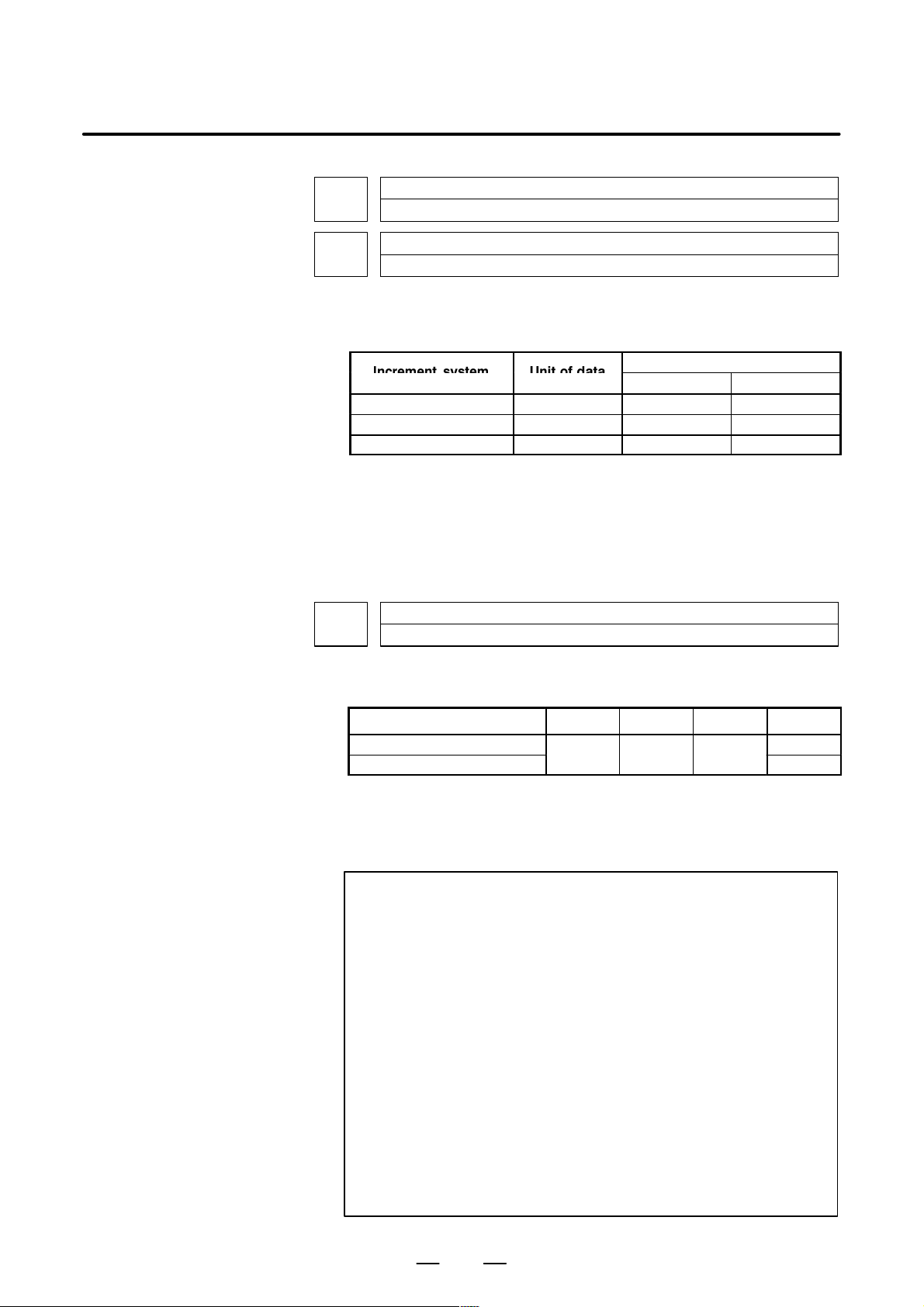
B–63610EN/01
I
Unitofdat
4. DESCRIPTION OF PARAMETERS
1460
1461
[Data type] 2–word
[Unit of data]
[Valid data range]
1465
Upper limit of feedrate for the one–digit F code command (F1 to F4)
Upper limit of feedrate for the one–digit F code command (F5 to F9)
ncrementsystem
Millimeter machine 1 mm/min 6 to 15000 6 to 12000
Inch machine 0.1 inch/min 6 to 6000 6 to 4800
Rotaion axis 1 deg/min 6 to 15000 6 to 12000
a
Valid data range
IS-A, IS-B IS-C
Set the upper limit of feedrate for the F1-digit feed command.
As the feedrate increases by turning the manual pulse generator, the
feedrate is clamped when it reaches the upper limit set. If an F1-digit feed
command F1 to F4 is executed, the upper limit is that set in parameter
1460. If an F1-digit command F5 to F9 is executed, the upper limit is that
set in parameter 1461.
Virtual radius for feedrate control about rotation axis
[Data type] 2–word
[Unit of data]
Increment system IS–A IS–B IS–C Unit
Metric input mm
Inch input
[Valid data range] 0 to 99999999
Set the radius of a virtual circle when using such a control method that the
feedrate of a rotation axis is converted to a travel speed on a circle of a
virtual radius.
NOTE
1 Note that the increment system remains unchanged
regardless of whether metric input or inch input is used.
2 This function is enabled when bit 0 (ROTx) of parameter No.
1006 and bit 0 (RFDx) of parameter No. 1408 are set to 1.
3 Be careful when setting bit 0 (RFDx) of parameter No. 1408
and parameter No. 1465 (virtual radius). In particular , when
this function is used with a small virtual radius value, axis
movement speeds up.
4 If a large value is set for the amount of travel and parameter
No. 1465 (virtual radius), an alarm (P/S 5307: Internal data
exceeded an allowable range.) is issued.
5 This function cannot be used in the following modes:
Rapid traverse, feed per revolution (G94), threading, AI
look–ahead control, high–speed remote buffer A,
high–speed remote buffer B
0.01 0.001 0.0001
inch
71
Page 78
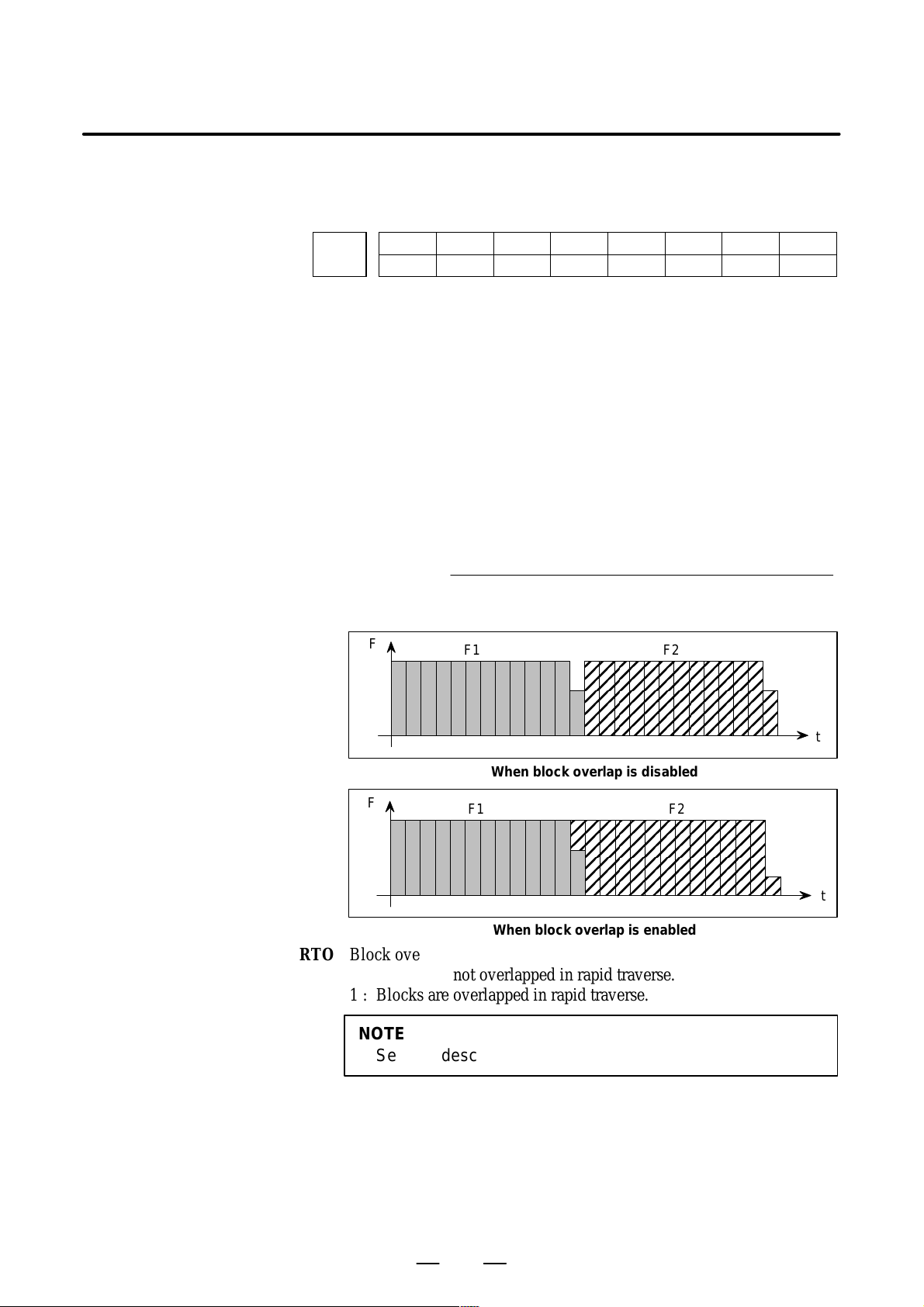
4. DESCRIPTION OF PARAMETERS
É
ÉÉÉ
É
4.16
P ARAMETERS OF ACCELERATION/ DECELERATION CONTROL
(Number of pulses to be added) = F2
[Data type] Bit
1601
OVB Block overlap in cutting feed
B–63610EN/01
#7
#6 #5
NCI
NCI
#4
RTO
RTO
#3 #2
OVB
#1 #0
0: Blocks are not overlapped in cutting feed.
1: Blocks are overlapped in cutting feed.
Block overlap outputs the pulses remaining at the end of pulse
distribution in a block together with distribution pulses in the next block.
This eliminates changes in feedrates between blocks.
Block overlap is enabled when blocks containing G01, G02, or G03 are
consecutively specified in G64 mode. If minute blocks, however, are
specified consecutively, overlap may not be performed.
The following pulses in block F2 are added to the pulses remaining at the
end of pulse distribution in block F1.
(Number of pulses required at the end of block F1)
F1
When F1 = F2
F
F
F1 F2
When block overlap is disabled
F1 F2
When block overlap is enabled
RTO Block overlap in rapid traverse
0 : Blocks are not overlapped in rapid traverse.
1 : Blocks are overlapped in rapid traverse.
NOTE
See the description of parameter No.1722.
t
t
NCI Inposition check at deceleration
0 : Performed
1 : Not performed
72
Page 79
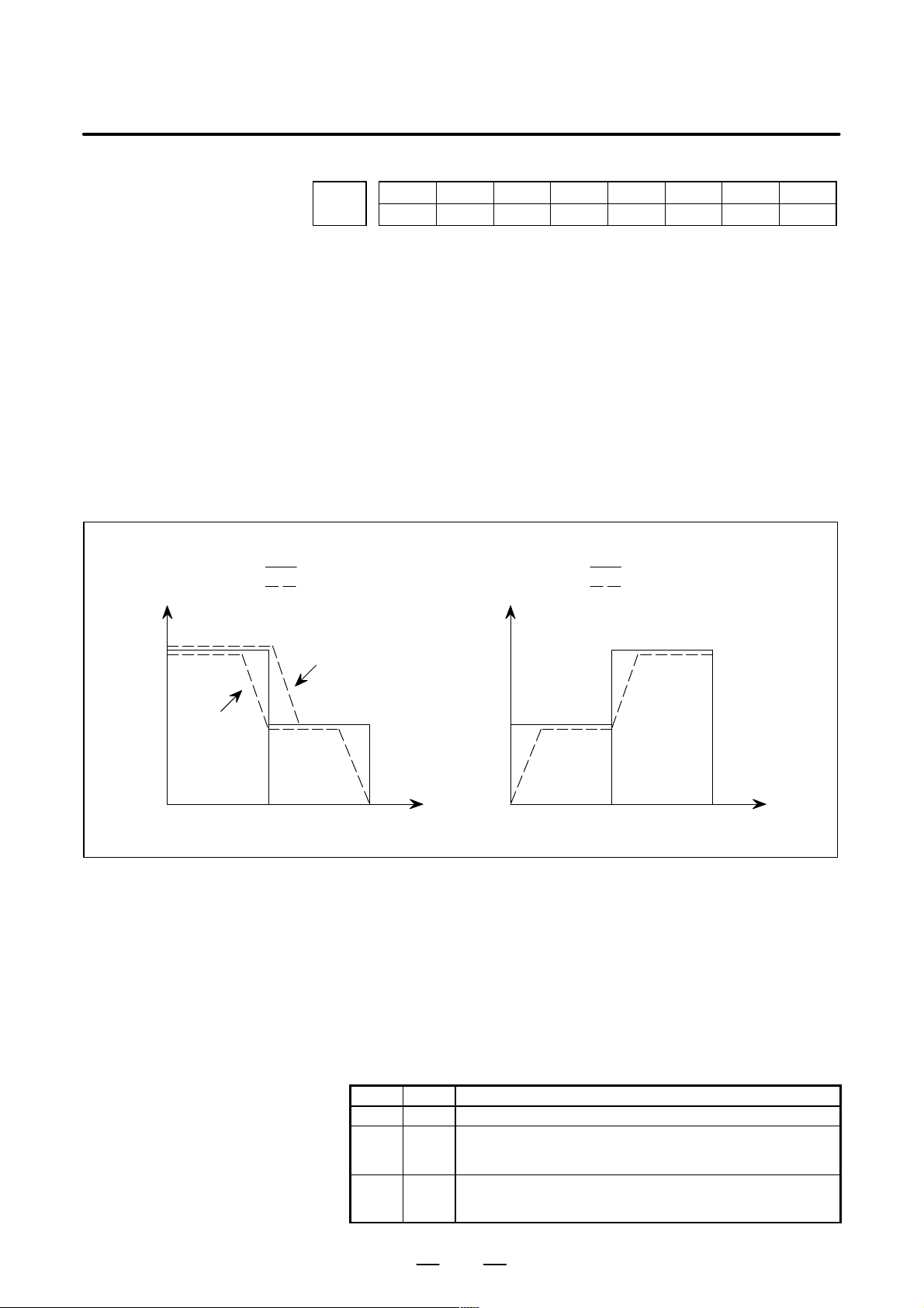
B–63610EN/01
4. DESCRIPTION OF PARAMETERS
#7
1602
#6
LS2
#5
G8S
G8S
#4
CSD
#3
BS2
#2
COV
#1 #0
[Data type] Bit
FWB Cutting feed acceleration/deceleration before interpolation
0 : Type A of acceleration/deceleration before interpolation is used.
1 : Type B of acceleration/deceleration before interpolation is used.
Type A: When a feedrate is to be changed by a command,
acceleration/deceleration starts after the program enters the
block in which the command is specified.
Type B: When a feedrate is to be changed by a command, deceleration
starts and terminates at the block before the blcock in which the
command is specified.
When a feedrate is to be changed by a command, acceleration
starts after the program enters theblock in which the command
is specified.
<Example of a deceleration process> <Example of a acceleration process>
Feedrate
F3
Point 1
Specified feedrate
Feedrate after acceleration/
deceleration before interpolation is applied
Type A
Feedrate
F3
Specified feedrate
Feedrate after acceleration/
deceleration before interpolation is applied
FWB
F2
F1
Type B
Time
N1 N2
To change the feedrate from F3 to F2, it is necessary to start reducing the feedrate at point 1.
F2
F1
N1 N2
COV The outer arc cutting feedrate change function of the automatic corner
override function is:
0 : Not used.
1 : Used.
BS2 Acceleration/deceleration after interpolation for cutting feed in
look–ahead control mode is:
0 : Exponential acceleration/deceleration or linear acceleration/
deceleration (one of which is selected by the LS2 parameter (bit 6 of
parameter No.1602)).
1 : Bell–shaped acceleration/deceleration.
BS2 LS2 Acceleration/deceleration
0 0 Exponential acceleration/deceleration after interpolation
0 1 Linear acceleration/deceleration after interpolation. (The
1 0 Bell–shaped acceleration/deceleration after interpolation.
option for linear acceleration/deceleration after interpolation
for cutting feed is required.)
(The option for bell–shaped acceleration/deceleration after
interpolation for cutting feed is required.)
Time
73
Page 80

4. DESCRIPTION OF PARAMETERS
CSD In the function for automatically reducing a feedrate at corners,
G8S Serial spindle look–ahead control is:
B–63610EN/01
0 : Angles are used for controlling the feedrate.
1 : Differences in feedrates are used for controlling the feedrate.
0 : Disabled.
1 : Enabled.
When enabled, look–ahead control can be applied to the following
functions:
D Rigid tapping
D Cs contour control
D Spindle positioning (only when bit 3 of parameter No.1800 is 1)
NOTE
1 FAD (fine acceleration/deceleration) cannot be applied to
the spindles. When serial spindle look–ahead control is
applied, therefore, FAD cannot be used for the servo axes.
2 For Cs contour control, look–ahead control is valid only for
the first spindle. Cs contour control with the second spindle
does not support look–ahead control.
LS2 Acceleration/deceleration after interpolation for cutting feed in
look–ahead control mode is:
0 : Exponential acceleration/deceleration.
1 : Linear accel erat io n/ d ecelerat i on . ( The fu nct i on fo r l in ear a ccelerat i on /
deceleration after interpo lation for cu tting feed is required.)
#7
1603
#6
RBL
#5 #4
RPT
RPT
#3 #2 #1 #0
[Data type] Bit
RPT The acceleration/deceleration of interpolation–type rapid traverse is
performed:
0: With a constant inclination.
1: With a constant time.
NOTE
This parameter is invalid if the function of bell–shaped
acceleration/deceleration after rapid–traverse
interpolation is provided. The acceleration/deceleration
time constant and override for rapid traverse are used.
RBL In the AI look–ahead control mode, acceleration/deceleration of rapid
traverse is:
0: Linear acceleration/deceleration.
1: Bell–shaped acceleration/deceleration.
NOTE
Bit 4 (RPT) of parameter No. 1603 is invalid.
74
Page 81

B–63610EN/01
4. DESCRIPTION OF PARAMETERS
#7
1610
#6 #5 #4
JGLx
#3 #2 #1
[Data type] Bit axis
CTLx Acceleration/deceleration in cutting feed including feed in dry run
0 : Exponential acceleration/deceleration is applied.
1 : Linear acceleration/deceleration after interpolation is applied.
NOTE
If the optional function of linear acceleration/deceleration
after interpolation in cutting feed is not provided, exponential
acceleration/deceleration is used irrespective of this setting.
To use bell–shaped acceleration/deceleration after
interpolation, set this parameter to 0 and select the
acceleration/deceleration using CTBx, bit 1 of parameter
No.1610.
Parameter
CTBx CTLx
0 0 Exponential acceleration/deceleration
0 1 Linear acceleration/deceleration after interpolation
1 0 Bell–shaped acceleration/deceleration after interpolation
Acceleration/deceleration
CTBx Acceleration/deceleration in cutting feed including feed in dry run
0 : Exponential acceleration/deceleration or linear acceleration/decel-
eration after interpolation is applied (depending on the setting in
CTLx, bit 0 of parameter No.1610).
1 : Bell–shaped acceleration/deceleration after interpolation is applied.
CTBx#0CTLx
NOTE
This parameter is effective only when the function of
bell–shaped acceleration/deceleration after interpolation in
cutting feed is provided. If the function is not provided, the
setting in CTLx, bit 0 of parameter No.1610, determines the
type of acceleration/deceleration irrespective of the setting
in this parameter.
JGLx Acceleration/deceleration in jog feed
0 : Exponential acceleration/deceleration is applied.
1 : Linear acceleration/deceleration after interpolation or bell–shaped
acceleration/deceleration after interpolation is applied (depending on
which is used for cutting feed).
75
Page 82
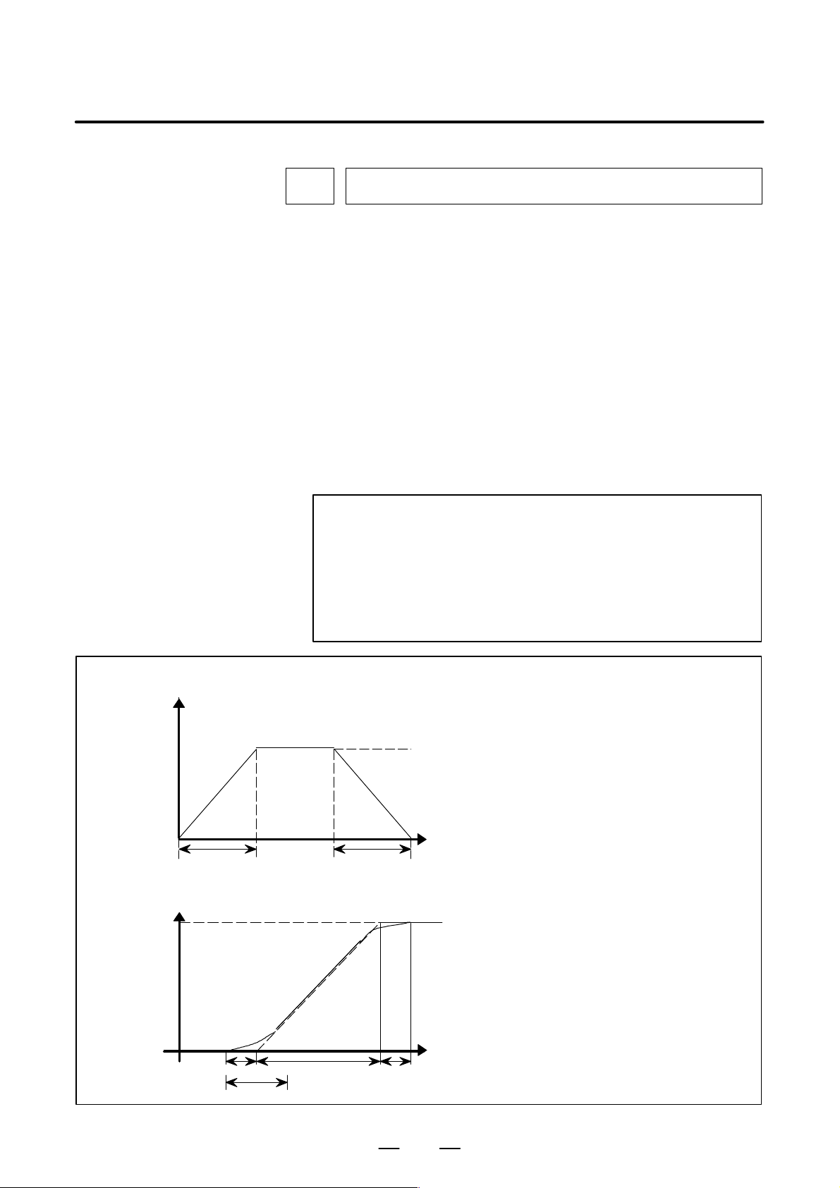
4. DESCRIPTION OF PARAMETERS
B–63610EN/01
1620
Time constant T or T1 used for linear acceleration/deceleration or bell–shaped
acceleration/deceleration in rapid traverse for each axis
[Data type] Word axis
[Unit of data] ms
[Valid data range] 0 to 4000
Specify a time constant used for acceleration/deceleration in rapid traverse. When the optional function of bell–shaped acceleration/decelera-
tion in rapid traverse is provided, bell–shaped acceleration/deceleration is
applied in rapid traverse. If the function is not provided, linear acceleration/deceleration is applied.
(1) When the function is provided, set this parameter to time constant T
used in bell–shaped acceleration/deceleration in rapid traverse, and
set parameter No.1621 to time constant T
(2) When the function is not provided, specify a time constant used in
linear acceleration/deceleration.
NOTE
When parameter No.1621 (time constant T2 used for
bell–shaped acceleration/deceleration in rapid traverse) is
set to 0, linear acceleration/deceleration is applied in rapid
traverse even if the function is provided. In this case, this
parameter stands for a time constant used in linear
acceleration/deceleration in rapid traverse.
1
.
2
<Rapid traverese linear acceleration/deceleration>
Speed
T
<Rapid traverse bell shaped acceleration/deceleration>
Speed
Rapid
traverse rate
T2/2
T
2
T
1
T
T2/2
Rapid traverse feed rate
Time
TIme
T: Time constant for linear
T1: Set a time constant used for lin-
: Set a time for rounding.
T
2
T otal time=T1 + T
Time for linear=T1 – T
Time for rounding part=T
acceleration/deceleration
ear acceleration/deceleration
2
2
2
76
Page 83

B–63610EN/01
4. DESCRIPTION OF PARAMETERS
Set the value when the rapid traverse rate is 100%. If it is under 100%, the
total time is reduced. (Constant acceleration method)
The value of T
value of T
1621
[Data type] Word axis
[Unit of data] ms
[Valid data range] 0 to 512
Specify time constant T
in rapid traverse for each axis.
NOTE
1 This parameter is effective when the function of bell–shaped
acceleration/deceleration in rapid traverse is provided. Set
parameter No.1620 to time constant T
bell–shaped acceleration/deceleration in rapid traverse, and
set this parameter to time constant T
For details of time constants T
of parameter No.1620.
2 When this parameter is set to 0, linear acceleration/
deceleration is applied in rapid traverse. The setting in
parameter No.1620 is used as a time constant in linear
acceleration/deceleration.
is determined from the torque of motor. Usually set the
1
to 24 ms ir 32 ms.
2
Time constant t T2 used for bell–shaped acceleration/deceleration in rapid traverse for each axis
used for bell–shaped acceleration/deceleration
2
used for
1
.
2
and T2, see the description
1
1622
Time constant of exponential acceleration/deceleration or bell–shaped acceleration/deceleration after interpolation, or linear aceeleration/deceleration after
interpolation in cutting feed for each axis
[Data type] Word axis
[Unit of data] ms
[Valid data range] 0 to 4000(exponential acceleration/deceleration in cutting feed)
0 to 512 (linear or bell–shaped acceleration/deceleration after
interpolation in cutting feed)
Set the time constant used for exponential acceleration/deceleration in
cutting feed, bell–shaped acceleration/deceleration after interpolation or
linear acceleration/deceleration after interpolation in cutting feed for each
axis. Except for special applications, the same time constant must be set
for all axes in this parameter . If the time constants set for the axes dif fer
from each other, proper straight lines and arcs cannot be obtained.
This parameter is valid for threading, irrespective of the
acceleration/deceleration type. For threading cycles G76 and G92 (G78
in the G code system B or C), this parameter is valid for operations other
than exponential acceleration/deceleration. (T series)
77
Page 84
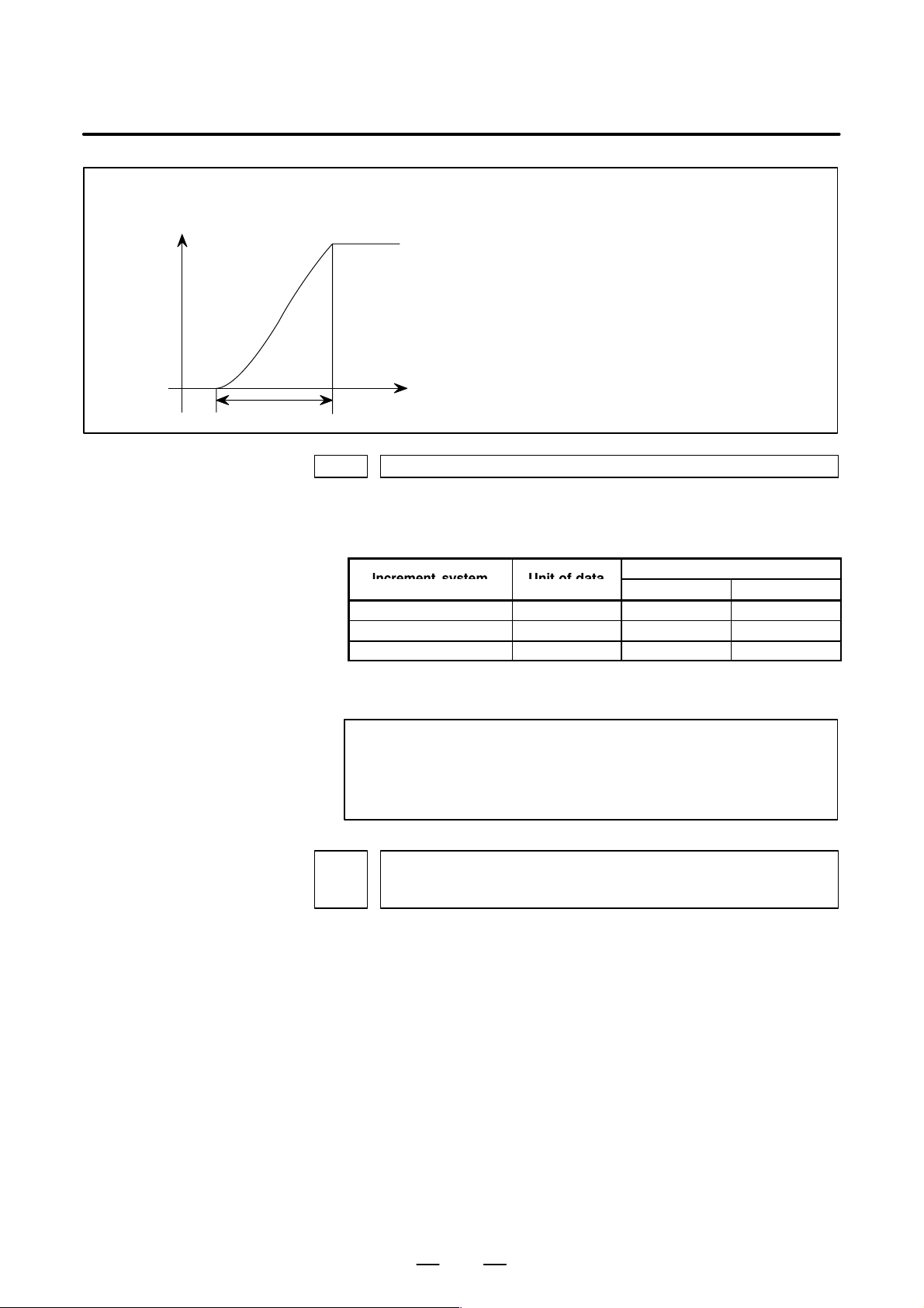
4. DESCRIPTION OF PARAMETERS
I
Unitofdat
Bell–shaped acceleraton/deceleration after cutting feed interpolation
Speed
T : T otal time. it is constant irrespective of feed rate.
(Time constant is constant).
B–63610EN/01
T
1623 FL rate of exponential acceleration/deceleration in cutting feed for each axis
[Data type] Word axis
[Unit of data]
[Valid data range]
The curve corresponds to that T
rameter No.1620 and 1621.
Time
ncrementsystem
Millimeter machine 1 mm/min 0,6 to 15000 0,6 to 12000
Inch machine 0.1 inch/min 0,6 to 6000 0,6 to 4800
Rotaion axis 1 deg/min 0,6 to 15000 0,6 to 12000
= T/2 and T2 = T/2 set in pa-
1
a
Valid data range
IS-A, IS-B IS-C
Set the lower limit (FL rate) of exponential acceleration/deceleration in
cutting feed for each axis.
NOTE
Except for special applications, this parameter must be set
to 0 for all axes. If a value other than 0 is specified, proper
straight lines and arcs cannot be obtained.
Time constant of exponential acceleration/deceleration or bell–shaped accelera-
1624
tion/deceleration or linear acceleration/deceleration after interpolation, in jog
feed for each axis.
[Data type] Word axis
[Unit of data] ms
[Valid data range] 0 to 4000(exponential acceleration/deceleration in jog feed)
0 to 512 (linear or bell–shaped acceleration/deceleration after
interpolation in jog feed)
Set the time constant used for exponential acceleration/deceleration,
bell–shaped acceleration/deceleration or linear acceleration/deceleration
after interpolation in jog feed fot each axis. The type to select depends
on the settings of the parameters CTLx, CTBx, and JGLx (Nos. 1610#0,
#1, and #4).
78
Page 85
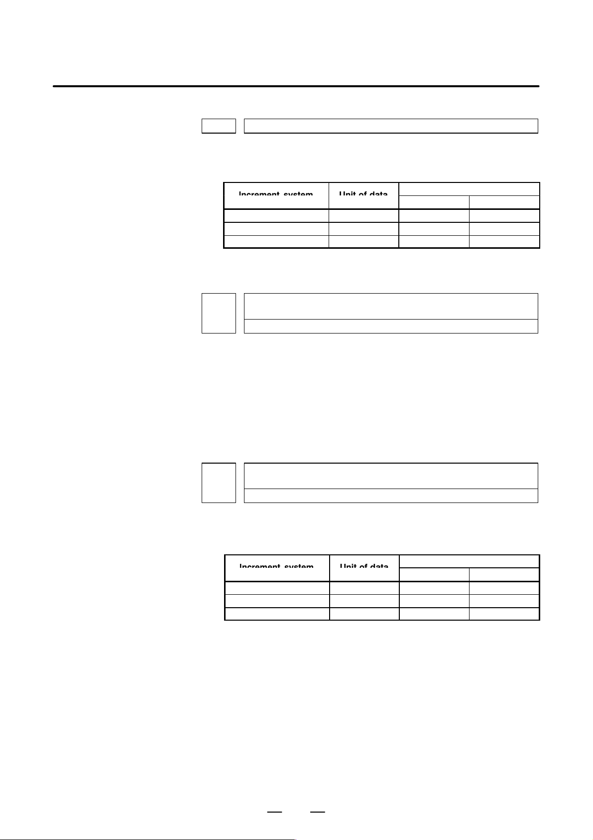
B–63610EN/01
I
Unitofdat
I
Unitofdat
1625 FL rate of exponential acceleration/deceleration in jog feed for each axis.
[Data type] Word axis
[Unit of data]
[Valid data range]
1626
[Data type] Word axis
4. DESCRIPTION OF PARAMETERS
ncrementsystem
Millimeter machine 1 mm/min 6 to 15000 6 to 12000
Inch machine 0.1 inch/min 6 to 6000 6 to 4800
Rotaion axis 1 deg/min 6 to 15000 6 to 12000
a
Valid data range
IS-A, IS-B IS-C
Set the lower limit (FL rate) of exponential acceleration/deceleration in
cutting feed for each axis.
Time constant of exponetial acceleration/deceleration in the thread cutting cycle
for each axis
[Unit of data] ms
[Valid data range] 0 to 4000
Set the time constant used for exponential acceleration/deceleration in the
thread cutting cycle (G76, G78 (G92 in G code system A)) for each axis.
If the acceleration type is not exponential acceleration/deceleration,
parameter No. 1622 becomes valid.
FL rate of exponential acceleration /deceleration in the thread cutting cycle for
1627
each axis
[Data type] Word axis
[Unit of data]
[Valid data range]
ncrementsystem
Millimeter machine 1 mm/min 6 to 15000 6 to 12000
Inch machine 0.1 inch/min 6 to 6000 6 to 4800
Rotaion axis 1 deg/min 6 to 15000 6 to 12000
Set the lower limit (FL rate) of exponential acceleration/deceleration in the
thread cutting cycle (G76, G78 (G92 in G code system A)) for each axis.
a
Valid data range
IS-A, IS-B IS-C
79
Page 86
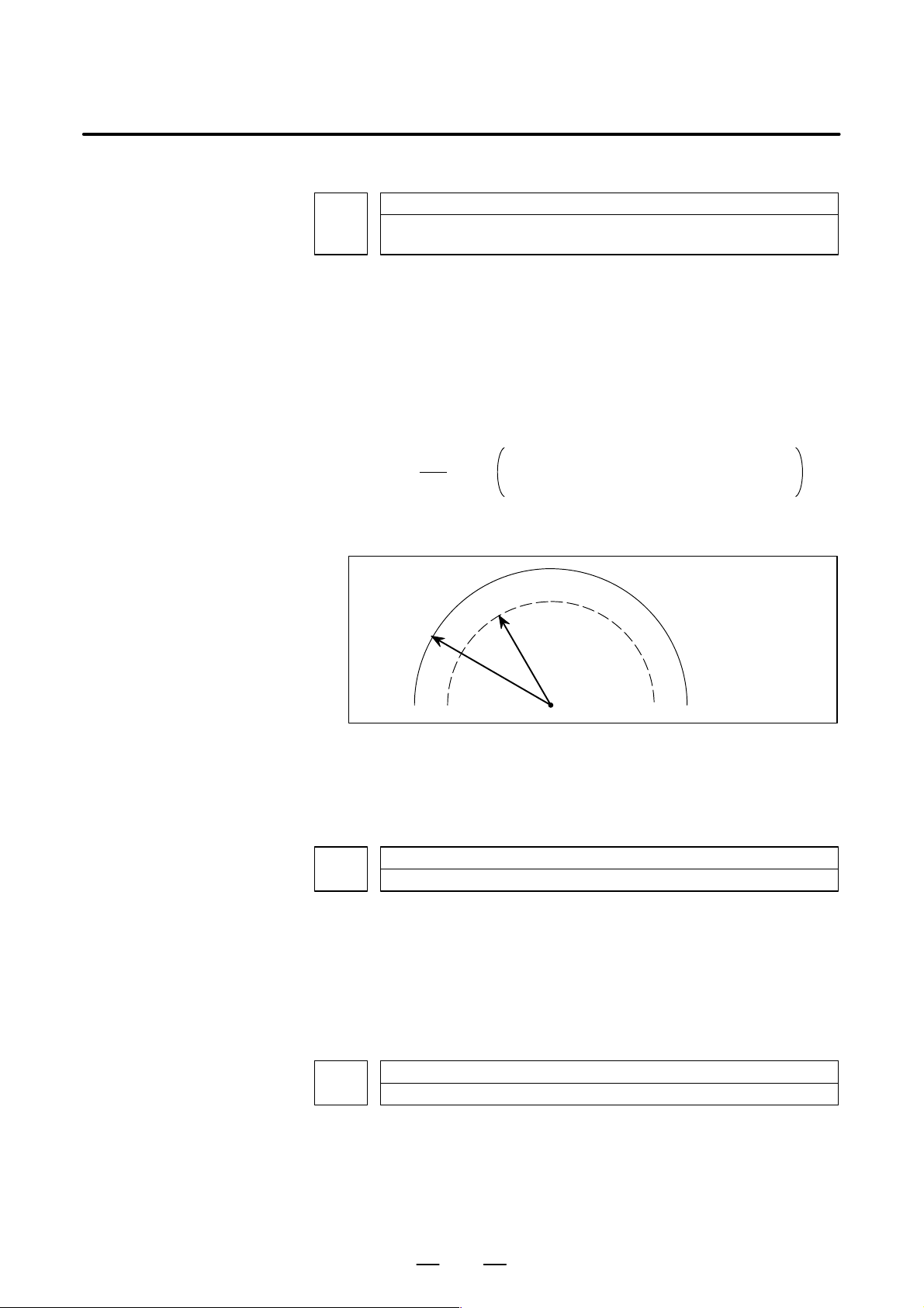
4. DESCRIPTION OF PARAMETERS
B–63610EN/01
1710
[Data type] Byte
[Unit of data] %
[Valid data range]
Minimum deceleration ratio (MDR) of the inner circular cutting rate in automatic
corner override
1 to 100
This parameter sets the minimum deceleration ratio (MDR) when the
inner circular cutting speed is changed by automatic corner override.
In circular cutting with an inward offset, the actual feedrate for a specified
feedrate (F) is expressed as follows:
Rc
Rp
F
Rc: Radius of the path of the cutter’s center.
Rp: Programmed radius
Then, the actual feedrate is controlled so that the feedrate on the
programmed path can achieve the specified feedrate F.
Rc
Programmed path
Rp
Path of the
cutter’s center
Fig. 4.16 (a) Rp and Rc
If Rc is too small in comparison with Rp, such that Rc/Rp 8 0, the cutter
will stop. To prevent this, a minimum deceleration ratio (MDR) is set.
1711
Angle (θp) used to recognize an inner corner in inner corner override
[Data type] Byte
[Unit of data] Degree
[Valid data range] 1 to 179 (standard value = 91)
This parameter sets the angle used to recognize an inner corner for inner
corner override by automatic corner override.
1712
Amount of override for an inner corner
[Data type] Byte
[Unit of data] %
[Valid data range]
1 to 100 (standard value = 50)
Set the amount of override for an inner corner.
80
Page 87
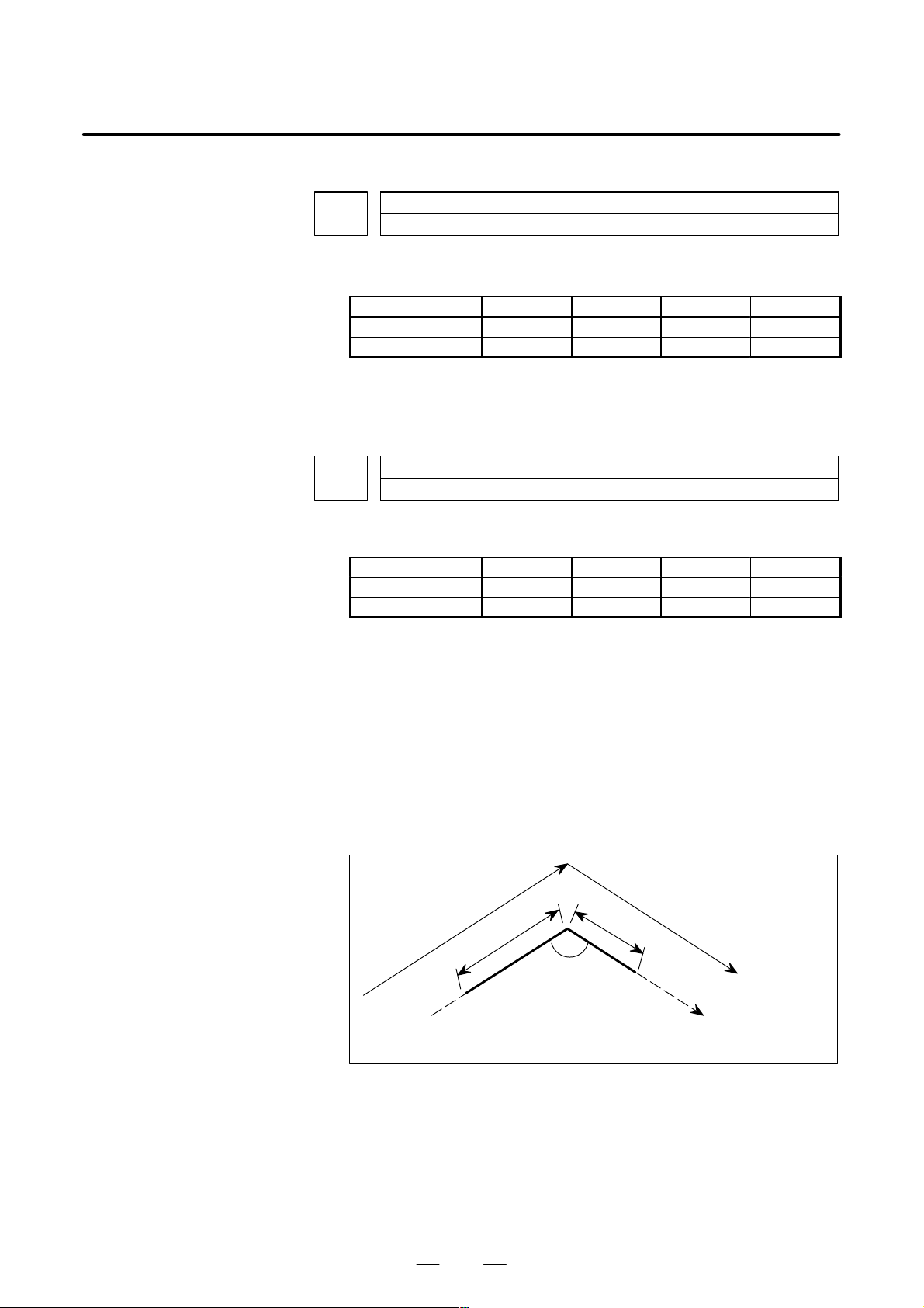
B–63610EN/01
4. DESCRIPTION OF PARAMETERS
1713
[Data type] Word
[Unit of data]
Increment system IS–A IS–B IS–C Unit
Millimeter input 1 0.1 0.01 mm
Inch input 0.1 0.01 0.001 inch
[Valid data range] 0 to 3999
Set distance Le from the starting point in an inner comer for corner
override.
1714
[Data type] Word
[Unit of data]
Increment system IS–A IS–B IS–C Unit
Millimeter input 1 0.1 0.01 mm
Inch input 0.1 0.01 0.001 inch
[Valid data range] 0 to 3999
Distance Le from the starting point in inner corner override
Distance Ls up to the ending point in inner corner override
Set distance Ls up to the end point in an inner corner for corner override.
If qx qp, the inside of a comer is recognized. (qp is set in parameter
1711.)
When an inner corner is recognized, the feedrate is overridden in the range
of Le in the block immediately before the intersection of the corner and Ls
in the next block following the intersection.
Ls and Le are each a straight line connecting the intersection of the corner
and a given point on the path of the cutter’s center.
Ls and Le are set in parameters 1713 and 1714.
Le
θ
a
An override is applied from point a to b.
Fig.4.16 (b) Distance Le and Ls in the automatic corner override at
an inner corner
Ls
b
Programmed
path
Cutter center
path
81
Page 88
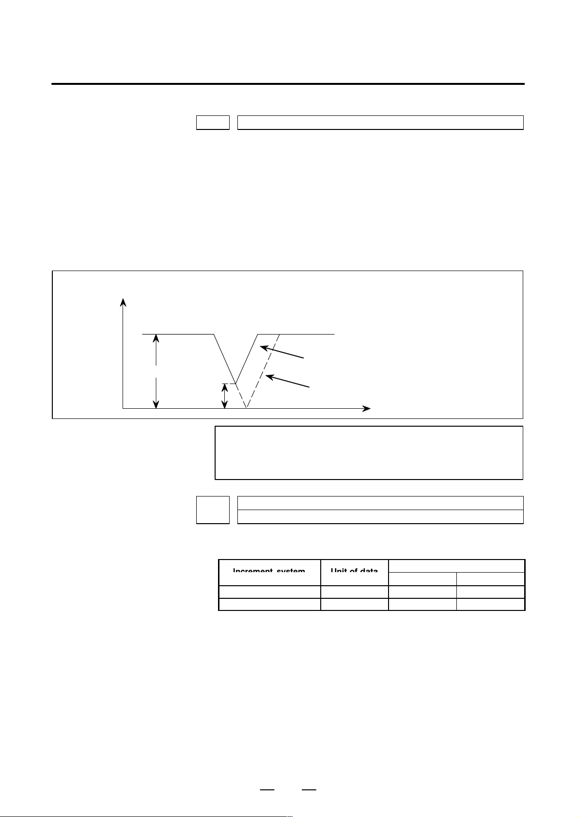
4. DESCRIPTION OF PARAMETERS
I
Unitofdat
1722 Rapid traverse feedrate reduction ratio for overlapping rapid traverse blocks
[Data type] Byte axis
[Unit of data] %
[Valid data range] 1 to 100
Examples
X–axis feedrate
N1 G00 X– – ; N2 G00 X– – ;
Fh
Fd
B–63610EN/01
This parameter is used when rapid traverse blocks are arranged
successively, or when a rapid traverse block is followed by a block that
does not cause, movement. When the feedrate for each axis of a block is
reduced to the ratio set in this parameter , the execution of the next block is
started.
Fh
: Rapid traverse feedrate
a
: Setting of parameter No.1722 (feedrate reduction ratio)
Fd
: Feedrate where deceleration is terminated: Fh x a/100
When the function of overlapping rapid
traverse blocks is enabled
When the function of overlapping rapid
traverse blocks is disabled
t
1730
[Data type] Word
[Unit of data]
NOTE
The parameter No.1722 is effective when parameter
No.1601 #4 (RT0) is set to 1.
Maximum feedrate for arc radius R
ncrementsystem
Millimeter machine 1 mm/min 8 to 15000 0 to 12000
Inch machine 0.1 inch/min 8 to 6000 0 to 4800
a
Valid data range
IS-A, IS-B IS-C
Set a maximum feedrate for the arc radius set in parameter No.1731. Set
this parameter when the arc radius–based feedrate clamping function is
enabled.
82
Page 89

B–63610EN/01
Increment system
Unit of data
I
Unitofdat
4. DESCRIPTION OF PARAMETERS
1731
Arc radius value corresponding to a maximum feedrate
[Data type] 2–word
[Unit of data]
Unit IS–A IS–B IS–C Unit
Linear axis
(millimeter machine)
Linear axis
(inch machine)
[Valid data range] 1000 to 99999999
Set the arc radius corresponding to the maximum feedrate set in parameter
No.1730. Set this parameter when the arc radius–based feedrate clamping
function is enabled.
1732
Minimum value (RV min) for arc radius–based feedrate clamp
[Data type] Word
Millimeter machine 1 mm/min 0 to 15000 0 to 12000
Inch machine 0.1 inch/min 0 to 6000 0 to 4800
0.01 0.001 0.0001 mm
0.001 0.0001 0.00001 inch
Valid data range
IS-A, IS-B IS-C
The arc radius–based feedrate clamping function reduces the maximum
feedrate as the arc radius decreases. When the specified maximum
feedrate is not greater than RV min (minimum value for arc radius–based
feedrate clamping), RV min is used as the maximum feedrate.
1762
Exponential acceleration/deceleration time constant for cutting feed in the look–
ahead control mode
[Data type] Word axis
[Unit of data] 1 ms
[Valid data range] 0 to 4000
Set an exponential acceleration/deceleration time constant for cutting
feed in the look–ahead control mode.
1763
Minimum speed in exponential acceleration/deceleration for cutting feed in the
look–ahead control mode
[Data type] Word axis
ncrementsystem
Millimeter machine 1 mm/min 6 to 15000 6 to 12000
Inch machine 0.1 inch/min 6 to 6000 6 to 4800
Rotation axis 1 deg/min 6 to 15000 6 to 12000
a
Valid data range
IS-A, IS-B IS-C
Set minimum speed (FL) in exponential acceleration/deceleration for
cutting feed in the look–ahead control mode.
83
Page 90
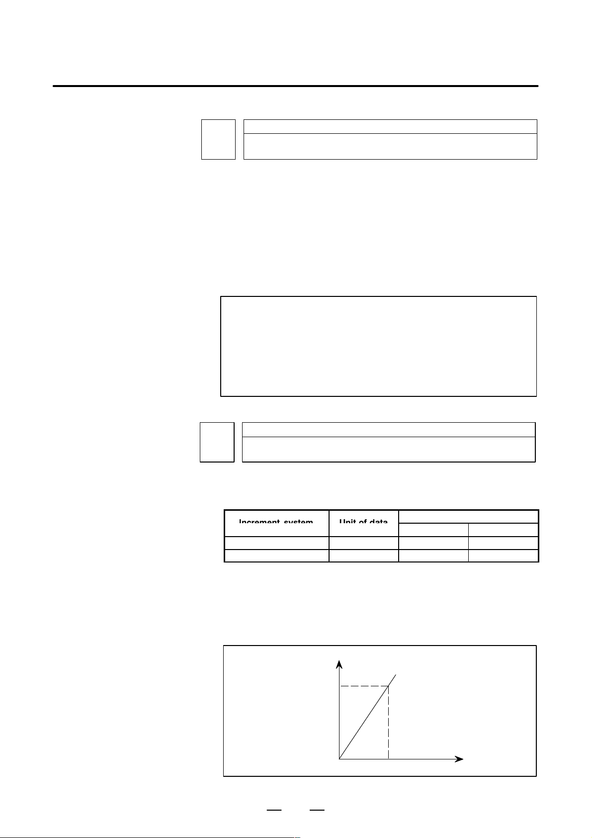
4. DESCRIPTION OF PARAMETERS
I
Unitofdat
B–63610EN/01
1768
[Data type] Word
[Unit of data] ms
[Valid data range] 8 to 512
This parameter sets a time constant for linear acceleration/deceleration or
bell–shaped acceleration/deceleration for cutting feed in the look–ahead
control mode.
Use parameter BS2 or LS2 (No.1602#3 or #6) to select the desired type.
NOTE
1 For linear acceleration/deceleration, the function of linear
acceleration/deceleration after cutting feed interpolation is
required.
2 For bell–shaped acceleration/deceleration, the function of
bell–shaped acceleration/deceleration after cutting feed
interpolation is required.
Time constant for linear acceleration/deceleration or bell–shaped acceleration/
deceleration during cutting feed in lock–ahead control mode.
1770 Parameter 1 (for look–ahead control) for setting an acceleration for linear ac-
[Data type] 2–word
[Unit of data, valid range]
ncrementsystem
Millimeter machine 1 mm/min 6 to 240000 6 to 100000
Inch machine 0.1 inch/min 6 to 96000 6 to 48000
This parameter is used to set an acceleration for linear acceleration/
deceleration before interpolation in the look–ahead control mode. In this
parameter , set the maximum machining speed during linear acceleration/
deceleration before interpolation. Set the time used to reach the
maximummachining speed in parameter No.1771.
celeration/deceleration before interpolation (maximum machining speed during
linear acceleration/deceleration before interpolation)
a
Speed
Parameter 1
(No.1770)
Valid data range
IS-A, IS-B IS-C
Parameter 2 (No.1771)
Time
84
Page 91

B–63610EN/01
I
Unitofdat
4. DESCRIPTION OF PARAMETERS
NOTE
When 0 is set in parameter No.1770 or parameter No.1771,
linear acceleration/deceleration before interpolation is
disabled.
1771 Parameter 2 (for look–ahead control) for setting an acceleration for linear ac-
celeration/deceleration before interpolation (time used to reach the maximum
machining speed during linear acceleration/deceleration before interpolation)
[Data type] Word
[Unit of data] 1 msec
[Valid range] 0 to 4000
This parameter is used to set an acceleration for linear acceleration/
deceleration before interpolation in the look–ahead control mode. In this
parameter, set the time (time constant) used toreach the speed set in
parameter No.1770.
NOTE
1 When 0 is set in parameter No.1770 or parameter No.1771,
linear acceleration/deceleration before interpolation is
disabled.
2 In parameter Nos. 1770 and 1771, set values that satisfy the
following:
Parameter No.1770/Parameter No.1771 y 5
1777
Minimum speed for the automatic corner deceleration function (look–ahead control)
[Data type] Word
[Unit of data, valid range]
ncrementsystem
Millimeter machine 1 mm/min 6 to 15000 6 to 12000
Inch machine 0.1 inch/min 6 to 6000 6 to 4800
Set a speed at which the number of buffered pulses in deceleration is
assumed to be 0 when linear acceleration/deceleration before
interpolation is used.
1779
Critical angle subtended by two blocks for automatic corner deceleration (for
look–ahead control)
[Data type] 2–word
[Unit of data] 0.001 deg
[Valid data range] 0 to 180000
Set a critical angle to be subtended by two blocks for corner deceleration
when the angle–basedautomatic corner deceleration function is used.
The angle subtended by two blocks is defined as θ in the examples shown
below.
a
Valid data range
IS-A, IS-B IS-C
85
Page 92

4. DESCRIPTION OF PARAMETERS
I
Unitofdat
I
Unitofdat
Block A (G01)
B–63610EN/01
θ
Angle subtended by two straight lines
Block B (G01)
1780
Allowable speed difference for the speed dif ference–based corner deceleration
function (for look–ahead control)
[Data type] Word
[Unit of data, valid range]
ncrementsystem
Millimeter machine 1 mm/min 6 to 15000 6 to 12000
Inch machine 0.1 inch/min 6 to 6000 6 to 4800
Set the speed difference for the speed difference–based automatic corner
deceleration function when linear acceleration/deceleration before
interpolation is used.
θ
Block A (G02)
Block B (G01)
Angle subtended by an arc and its tangent
a
IS-A, IS-B IS-C
Valid range
1783
[Data type] Word axis
[Unit of data, valid range]
Millimeter machine 1 mm/min 6 to 15000 6 to 12000
Inch machine 0.1 inch/min 6 to 6000 6 to 4800
Rotation axis 1 deg/min 6 to 15000 6 to 12000
A separate allowable feedrate difference can be set for each axis. The
allowable feedrate difference is set for each axis with this parameter.
Among the axes that exeed the specified allowable feedrate difference, the
axis with the greatest ratio of the actual feedrate difference to the
allowable feedrate difference is used as the reference to calculate the
reduced feedrate at the corner.
Allowable speed difference for the speed dif ference based corner deceleration
function (for look–ahead control)
ncrementsystem
a
IS-A, IS-B IS-C
Valid range
86
Page 93

B–63610EN/01
I
Unitofdat
4. DESCRIPTION OF PARAMETERS
1784
[Data type] Word axis
[Unit of data]
[Valid data range]
Speed when overtravel alarm has generated during acceleration/deceleration
before interpolation (for look–ahead control)
ncrementsystem
Millimeter machine 1 mm/min 6 to 15000 6 to 12000
Inch machine 0.1 inch/min 6 to 6000 6 to 4800
Rotation axis 1 deg/min 6 to 15000 6 to 12000
a
IS-A, IS-B IS-C
Valid range
Deceleration is started beforehand to reach the feedrate set in the
parameter when an overtravel alarm is issued (when a limit is reached)
during linear acceleration/deceleration before interpolation. By using
this parameter, the overrun distance that occurs when an overtravel alarm
is output can be reduced.
NOTE
1 When 0 is set in this parameter, the control described above
is not exercised.
2 Use type–B linear acceleration/deceleration before
interpolation (by setting bit 0 (FWB) of parameter No.1602
to 1).
3 The control described above is applicable only to stored
stroke check 1.
1785
Parameter for determining an allowable acceleration when the feedrate is set by
acceleration
[Data type] Word–axis
[Unit of data] ms
[Valid data range] 0 to 32767
This parameter sets the time required to attain the maximum cutting
feedrate to determine the allowable acceleration when the feedrate is
determined by acceleration in AI look–ahead control mode.
The maximum cutting feedrate and the data set in this parameter are used
to determine the allowable acceleration. As the maximum cutting
feedrate parameter , parameter No.1432 (maximum cutting feedrate in AI
look–ahead control mode) is used.
87
Page 94

4. DESCRIPTION OF PARAMETERS
4.17
PARAMETERS OF SERVO
[Data type] Bit
1800
CVR When velocity control ready signal VRDY is set ON before position
OZR When manual reference position return is attempted in the halt state
B–63610EN/01
#7
#6 #5
TRC
#4
RBK
#3
FFR
#2
OZR
#1
CVR
#0
control ready signal PRDY comes ON
0: A servo alarm is generated.
1: A servo alarm is not generated.
during automatic operation (feed hold stop state) under any of the
conditions listed below:
0: Manual reference position return is not performed, with P/S alarm
No.091.
1: Manual reference position return is performed without an alarm
occurring.
< Conditions >
(1) When there is a remaining distance to travel.
(2) When an auxiliary function (miscellaneous function, spindle–speed
function, tool function) is being executed.
(3) When a cycle such as a dwell cycle or canned cycle is being executed.
FFR Feed–forward control is enabled for
0 : Cutting feed only
1 : Cutting feed and rapid traverse
RBK Backlash compensation applied separately for cutting feed and rapid
traverse
0: Not performed
1: Performed
TRC The servo trace functon is:
0 : Disabled
1 : Enabled (Also set parameter No.1870.)
The digital servo software for learning control is necessary.
#7
1801
#6 #5
CIN
CIN
#4
CCI
CCI
#3
API
API
#2 #1
PM2
#0
PM1
[Data type] Bit
PM1, PM2 Sets a gear ratio between the spindle and motor when the servo
motor–based speed control function is used.
Magnification PM2
1/1
1/2
1/4
1/8
PM1
0
0
1
1
0
1
0
1
Magnification=
spindle speed
motor speed
API To use an absolute position detector for any axis, set API to 1.
88
Page 95
B–63610EN/01
4. DESCRIPTION OF PARAMETERS
CCI The in–position area for cutting feed is:
0 : Set in parameter No.1826 (same as for rapid traverse).
1 : Set in bit 5 (CIN) of parameter No.1801.
CIN When bit 4 (CCI) of parameter No.1801 = 1, the in–position area for
cutting feed is:
0 : Use value in parameter No.1827 if the next block is also for cutting
feed, or use value in parameter No.1826 if the next block is not for
cutting feed.
1 : Use value in parameter No.1827, regardless of the next block. (The
setting of parameter No.1826 is used for rapid traverse, and the setting
of parameter No.1827 is used for cutting feed.)
1802
#7
FWC
#6 #5
DPS
#4
B15
B15
#3 #2
DC2
DC2
NOTE
After this parameter is set, the power needs to be turned off.
[Data type] Bit
CTS The servo motor–based speed control function is:
0 : Not used
1 : Used
DC2 The reference position on the linear scale with absolute addressing
reference marks is established:
0: As determined by bit 1 (DC4) of parameter No. 1802.
1: By establishing the absolute position through detection of two
reference marks.
B15 In backlash compensation, the travel direction is determined:
0: Without consideration of the compensation amount (pitch error,
straightness, external machine coordinate shift, etc.).
1: In consideration of the compensation amount. (FS15 format)
DPS When servo motor–based speed control is applied, a position coder is:
0 : Used
1 : Not used
#1 #0
CTS
FWC The processing of command multiplication (CMR) is performed:
0: After acceleration/deceleration after interpolation.
1: Before acceleration/deceleration after interpolation.
#7
1803
#6 #5 #4
TQF
#3 #2 #1
TQA
[Data type] Bit
TQI While torque restriction is applied, in–position check is:
0 : Performed.
1 : Not performed.
TQA While torque restriction is applied, checking for an excessive error in the
stopped state/during movement is:
0 : Performed.
1 : Not performed.
89
#0
TQI
Page 96

4. DESCRIPTION OF PARAMETERS
TQF When torque control is performed by an axis control command of the
B–63610EN/01
PMC axis control function, follow–up operation is:
0 : Not performed.
1 : Performed.
#7
1804
#6
SAK
SAK
#5
ANA
ANA
#4
IVO
IVO
#3 #2 #1
BLC
[Data type] Bit axis
BLC During circular interpolation by jog feed (manual circular interpolation
function), the backlash acceleration function is:
0 : Disabled.
1 : Enabled.
IVO When an attempt is made to release an emergency stop while the VRDY
OFF alarm ignore signal is 1:
0 : The emergency stop state is not released until the VRDY OFF alarm
ignore signal is set to 0.
1 : The emergency stop state is released.
NOTE
When a reset is issued while the VRDY OFF alarm ignore
signal is set to 1 and the motor activating current is low, the
reset state can also be released, provided this parameter is
set to 1.
ANA When an abnormal load is detected for an axis:
0 : Movement along all axes is stopped, and a servo alarm is output.
1 : No servo alarm is output, and movement along only the axes of the
group containing the axis with the abnormal load is stopped in interlock
mode. (The group number of each axis is set in parameter No.1881.)
#0
SAK When the VRDY OFF alarm ignore signal IGNVRY is 1, or when the
VRDY OFF alarm ignore signals IGVRY1 to IGVRY8 are 1:
0 : Servo ready signal SA is set to 0.
1 : Servo ready signal SA remains set to 1.
#7
1805
#6 #5 #4 #3 #2 #1
TQU
[Data type] Bit
TQU If follow–up is not performed by the torque control command of PMC
axis control, the servo error counter is:
0: Updated.
1: Not updated.
NOTE
1 This parameter is valid if follow–up is not performed (bit 4
(TQF) of parameter No. 1803 is set to 0).
2 When torque control is switched to position control, a
reference position return must be made.
90
#0
Page 97

B–63610EN/01
4. DESCRIPTION OF PARAMETERS
#7
1815
#6 #5
APCx#4APZx
#3 #2
DCLx#1OPTx
NOTE
When this parameter has been set, the power must be
turned off before operation is continued.
[Data type] Bit axis
OPTx Position detector
0 : A separate pulse coder is not used.
1 : A separate pulse coder is used.
For an absolute–position system using Inductosyn, set this parameter to 1.
DCLx As a separate position detector, the linear scale with reference marks is:
0 : Not used.
1 : Used.
NOTE
When using the linear scale with reference marks, also set
the OPTx parameter (bit 1 of parameter No.1815) to 1.
APZx Machine position and position on absolute position detector when the
absolute position detector is used
0 : Not corresponding
1 : Corresponding
#0
NOTE
When an absolute position detector is used, after primary
adjustment is performed or after the absolute position
detector is replaced, this parameter must be set to 0, power
must be turned off and on, then manual reference position
return must be performed. This completes the positional
correspondence between the machine position and the
position on the absolute position detector, and sets this
parameter to 1 automatically.
APCx Position detector
0 : Other than absolute position detector
1 : Absolute position detector (absolute pulse coder)
For an absolute–position system using Inductosyn, set this parameter to 1.
1817
NOTE
When this parameter has been set, the power must be
turned off before operation is continued.
[Data type] Bit axis
#7
#6 #5 #4
SCPx
#3 #2 #1 #0
SCPx If bit 2 (DC2) of parameter No. 1802 is set to 1, the scale zero point of the
linear scale with absolute addressing reference marks is:
91
Page 98

4. DESCRIPTION OF PARAMETERS
B–63610EN/01
0: On the negative direction side. (V iewed from the scale zero point, the
reference position is on the positive direction side.)
1: On the positive direction side. (Viewed from the scale zero point, the
reference position is on the negative direction side.)
#7
1818
#6 #5 #4 #3 #2
DG0x#1RF2x#0RFSx
[Data type] Bit axis type
RFSx On an axis using a linear scale with absolute addressing reference marks,
if an automatic reference position return (G28) is made before the
reference position is established, the
then:
reference position is established first,
0: A movement to the reference position is made.
1: A movement to the reference position is not made, but the operation is
completed.
RF2x On an axis using a linear scale with absolute addressing reference marks,
if an automatic reference position return (G28) is made after the reference
position is established,
0: A movement to the reference position is made.
1: A movement to the reference position is not made, but the operation is
completed.
DG0x On an axis using a linear scale with absolute addressing reference marks, a
reference position return by jog feed or a rapid traverse command is:
0: Disabled.
1: Enabled.
#7
1819
#6 #5 #4 #3 #2
DATx
DATx
#1
CRFx
CRFx
[Data type] Bit axis
FUPx To perform follow–up when the servo is off is set for each axis.
0: The follow–up signal, *FLWU, determines whether follow–up is
performed or not.
When *FLWU is 0, follow–up is performed.
When *FLWU is 1, follow–up is not performed.
1: Follow–up is not performed.
NOTE
When the index table indexing function (M series) is used,
be sure to set FUPx of the 4th axis to 1.
CRFx When servo alarm No.445 (software disconnection), No.446 (hardware
disconnection), No.447 (hardware disconnection (separate type)), or
No.421 (excessive dual position feedback error) is issued:
0 : The reference position setting remains as is.
1 : The system enters the reference position undefined state.
DATx On a linear scale with absolute addressing reference marks, the automatic
setting of parameters No. 1883 and No. 1884 is:
0: Not performed.
1: Performed.
#0
FUPx
FUPxNAHx
92
Page 99
B–63610EN/01
4. DESCRIPTION OF PARAMETERS
NOTE
This parameter is automatically set to 0 when the manual
reference position return is completed.
NAHx In the look–ahead control mode, advanced feed–forward is:
0 : Used
1 : Not used
NOTE
Set1 for a PMC–based control axis.
1820 Command multiplier for each axis (CMR)
NOTE
When this parameter has been set, the power must be
turned off before operation is continued.
[Data type] Byte axis
Set a command multiplier indicating the ratio of the least command
increment to the detection unit for each axis.
Least command increment = detection unit command multiplier
Relationship between the increment system and the least command
increment
(1) T series
IS–B Millimeter Millimeter 0.001 mm (diameter specification) 0.0005 mm
machine input
machine input
IS–C Millimeter Millimeter 0.0001 mm (diameter specification) 0.00005 mm
machine input
machine input
Least
Least input increment
0.001 mm (radius specification) 0.001 mm
Inch input 0.0001 inch (diameter specification) 0.0005 mm
0.0001 inch (radius specification) 0.001 mm
Inch Millimeter 0.001 mm (diameter specification) 0.00005 inch
0.001 mm (radius specification) 0.0001 inch
Inch input 0.0001 inch (diameter specification) 0.00005 inch
0.0001 inch (radius specification) 0.0001 inch
Rotation axis 0.001 deg 0.001 deg
Least input increment
0.0001 mm (radius specification) 0.0001 mm
Inch input 0.00001 inch (diameter specification) 0.00005 mm
0.00001 inch (radius specification) 0.0001 mm
Inch Millimeter 0.0001 mm (diameter specification) 0.000005 inch
0.0001 mm (radius specification) 0.00001 inch
Inch input 0.00001 inch (diameter specification) 0.000005 inch
0.00001 inch (radius specification) 0.00001 inch
Rotation axis 0.0001 deg 0.0001 deg
command
increment
Least
command
increment
93
Page 100

4. DESCRIPTION OF PARAMETERS
B–63610EN/01
(2) M series
least command
increment
Increment
system
Millimeter machine 0.01 0.001 0.0001 mm
Inch machine 0.001 0.0001 0.00001 inch
Rotation axis 0.01 0.001 0.0001 deg
Least input increment and least command increment
IS–A IS–B IS–C Units
Setting command multiply (CMR), detection multiply (DMR), and the
capacity of the reference counter
X CMR
Reference
counter
Fig.4.17 (a) CMR, DMR, and the Capacity of the Reference Counter
+
–
Detection
unit
Error counter
Feedback pulse
X DMR
DA
Converter
Set the magnification ratios of CMR and DMR so that the weight of
positive inputs to the error counter equals that of negative inputs.
To velocity control
Position detector
Feedback pulse unit =
Least command increment
CMR
=detection unit=
feedback pulse unit
DMR
The feedback pulse unit varies according to the type of detector.
the amount of travel per rotation of the pulse coder
the number of pulses per rotation of the pulse coder (2000, 2500, or 3000)
As the size of the reference counter, specify the grid interval for the
reference position return in the grid method.
Size of the reference counter = Grid interval/detection unit
Grid interval = the amount of travel per rotation of the pulse coder
The value set in the parameter is obtained as follows:
(1) When command multiplier is 1/2 to 1/27
Set value =
1
+ 100
(Command multiplier)
Valid data range: 102 to 127
(2) When command multiply is 1 to 48
Set value = 2 command multiplier
Valid data range: 2 to 96
NOTE
When command multiplier is 1 to 48, the set value must be
determined so that an integer can be set for command
multiplier.
94
 Loading...