

Page 1

7169Fr4Hqa2ECQqEpRfd63ND/4NVqYNEFOTqTAv7RCUlwWzsC+2wd68VWEg==
FANUC Series 16+/160+/160+s-MODEL B
FANUC Series 18+/180+/180+s-MODEL B
FANUC Series 21+/210+/210+s-MODEL B
CONNECTION MANUAL (HARDWARE)
B-63523EN/03
© MyFANUC 19C934977F3A4E20A8A35A328E753C6E
Page 2

• The appearance and specifications of this product are subject to change without notice.
Foreign Exchange and
the government of Japan. Other models in this manual may also be subject to export
vernment of
Should you wish to export or re-export these products, please contact FANUC for advice.
er, a very large number of operations that must not or cannot be
being possible are "not possible".
which are registered trademarks of respective owners. However, these names are not
followed by or in the main body.
7169Fr4Hqa2ECQqEpRfd63ND/4NVqYNEFOTqTAv7RCUlwWzsC+2wd68VWEg==
• No part of this manual may be reproduced in any form.
The products in this manual are controlled based on Japan’s “
Foreign Trade Law”. The export of Series 16i from Japan is subject to an export license by
controls.
Further, re-export to another country may be subject to the license of the go
the country from where the product is re-exported. Furthermore, the product may also be
controlled by re-export regulations of the United States government.
In this manual, we endeavor to include all pertinent matters.
There are, howev
performed, and if the manual contained them all, it would be enormous in volume.
It is, therefore, requested to assume that any operations that are not explicitly described as
This manual contains the program names or device names of other companies, some of
© MyFANUC 19C934977F3A4E20A8A35A328E753C6E
Page 3

7169Fr4Hqa2ECQqEpRfd63ND/4NVqYNEFOTqTAv7RCUlwWzsC+2wd68VWEg==
B–63523EN/03
DEFINITION OF WARNING, CAUTION, AND NOTE
DEFINITION OF WARNING, CAUTION, AND NOTE
This manual includes safety precautions for protecting the user and preventing damage to the
machine. Precautions are classified into W arning and Caution according to their bearing on safety.
Also, supplementary information is described as a Note. Read the Warning, Caution, and Note
thoroughly before attempting to use the machine.
WARNING
Applied when there is a danger of the user being injured or when there is a danger of both the user
being injured and the equipment being damaged if the approved procedure is not observed.
CAUTION
Applied when there is a danger of the equipment being damaged, if the approved procedure is not
observed.
NOTE
The Note is used to indicate supplementary information other than Warning and Caution.
` Read this manual carefully, and store it in a safe place.
s–1
© MyFANUC 19C934977F3A4E20A8A35A328E753C6E
Page 4

7169Fr4Hqa2ECQqEpRfd63ND/4NVqYNEFOTqTAv7RCUlwWzsC+2wd68VWEg==
© MyFANUC 19C934977F3A4E20A8A35A328E753C6E
Page 5

7169Fr4Hqa2ECQqEpRfd63ND/4NVqYNEFOTqTAv7RCUlwWzsC+2wd68VWEg==
B–63523EN/03
PREFACE
PREFACE
This manual describes the electrical and structural specifications required
for connecting the CNC control unit to a machine tool. The manual
outlines the components commonly used for F ANUC CNC control units,
as shown in the configuration diagram in Chapter 2, and supplies
additional information on using these components. The manual outlines
the I/O unit, servo, spindle, and other components common to FANUC
CNC control units, and supplies additional information on using these
components in this CNC control unit. For detailed specifications, refer
to the manuals of these components.
For options not covered in this manual, also refer to the manuals of these
components.
Applicable models
The models covered by this manual, and their abbreviations, are :
Product Name Abbreviations
FANUC Series 16i–TB 16i–TB
FANUC Series 16i–MB 16i–MB
FANUC Series 18i–TB 18i–TB
FANUC Series 18i–MB5 18i–MB5
FANUC Series 18i–MB 18i–MB
FANUC Series 21i–TB 21i–TB
FANUC Series 21i–MB 21i–MB
FANUC Series 160i–TB 160i–TB
FANUC Series 160i–MB 160i–MB
FANUC Series 180i–TB 180i–TB
FANUC Series 180i–MB5 180i–MB5
FANUC Series 180i–MB 180i–MB
FANUC Series 210i–TB 210i–TB
FANUC Series 210i–MB 210i–MB
Series 16i
Series 18i
Series 21i
Series 160i
Series 180i
Series 210i
FANUC Series 160is–TB 160is–TB
FANUC Series 160is–MB 160is–MB
FANUC Series 180is–TB 180is–TB
FANUC Series 180is–MB5 180is–MB5
FANUC Series 180is–MB 180is–MB
FANUC Series 210is–TB 210is–TB
FANUC Series 210is–MB 210is–MB
p–1
© MyFANUC 19C934977F3A4E20A8A35A328E753C6E
Series 160is
Series 180is
Series 210is
Page 6

7169Fr4Hqa2ECQqEpRfd63ND/4NVqYNEFOTqTAv7RCUlwWzsC+2wd68VWEg==
PREFACE
Organization of this
manuals
Chapter and title Contents
Chapter 1
CONFIGURATION
Chapter 2
TOT AL CONNECTION DAIGRAMS
Chapter 3
INSTALLATION
Chapter 4
POWER SUPPLAY CONNECTION
Chapter 5
CONNECTION TO CNC PERIOHERALS
B–63523EN/03
This manual consists of chapters 1 to 15 and appendixes at the end of the
book.
Provides general information related to the connection of the i Series CNC, as well as an
introduction to detailed information.
Describes how to connect peripheral units to the i Series CNC.
Describes the installation requirements for using the i Series CNC.
1) Required power supply capacity
2) Heat output
3) Locations of connectors on the control unit
4) Action against noise
Describes how to make connections related to the power supply of the i Series CNC.
Describes how to connect the following peripheral devices to the i Series CNC:
1) MDI unit
2) I/O device (RS–232–C)
3) High–speed skip (HDI)
4) Built–in ethernet
Chapter 6
SPINDLE CONNECTION
Chapter 7
SERVO INTERF ACE
Chapter 8
CNC DISPLA Y UNIT WITH PC
FUNCTIONS
Chapter 9
CONNECTION TO FANUC I/O Link
Chapter 10
EMERGENCY STOP SIGNAL
Chapter 11
REMOTE BUFFER INTERFACE
(INCLUDING F ANUC DNC1 AND DNC2)
Chapter 12
HIGH–SPEED SERIAL BUS (HSSB)
Chapter 13
CONNECTION TO OTHER
NET–WORKS
Chapter 14
CONNECTION FOR Series
160is/180is/210is
Describes how to connect spindle–related units to the i Series CNC.
Describes how to connect servo–related units to the i Series CNC.
Describes how to connect a CNC display unit with PC functions to the i Series CNC.
Describes how to connect machine interface I/O with the FANUC I/O Link.
Describes how to handle the emergency stop signal.
Be sure to read this chapter.
Describes the remote buffer, DNC1, and DNC2 interfaces that can be used with the i Series CNC.
Describes the high–speed serial bus (HSSB) that can be used with the i Series CNC.
Describes how to connect the i Series CNC to networks.
Describes connection for Series 160is/180is/210is
APPENDIX A) EXTERNAL DIMENSIONS OF EACH UNIT
B) 20–PIN INTERFACE CONNECTORS AND CABLES
C) CONNECTION CABLE (SUPPLIED FROM US)
D) OPTICAL FIBER CABLE
E) LIQUID CRYST AL DISPLA Y (LCD)
F) MEMORY CARD INTERF ACE
p–2
© MyFANUC 19C934977F3A4E20A8A35A328E753C6E
Page 7

7169Fr4Hqa2ECQqEpRfd63ND/4NVqYNEFOTqTAv7RCUlwWzsC+2wd68VWEg==
B–63523EN/03
Related manuals of
Series 16i/18i/21i/160i/
180i/210i/160is/ 180is/
210is–MODEL B
PREFACE
The following table lists the manuals related to Series 16i, Series 18i,
Series 21i, Series 160i, Series 180i, Series 210i, Series 160is, Series
180is, Series 210is–MODEL B. This manual is indicated by an
asterisk(*).
Manual name
DESCRIPTIONS B–63522EN
CONNECTION MANUAL (HARDWARE) B–63523EN *
CONNECTION MANUAL (FUNCTION) B–63523EN–1
Series 16i/18i/160i/180i/160is/180is–TB
OPERATOR’S MANUAL
Series 16i/160i/160is–MB, Series 18i/180i/180is–MB5,
Series 18i/180i/180is–MB OPERATOR’S MANUAL
Series 21i/210i/210is–TB OPERATOR’S MANUAL B–63604EN
Series 21i/210i/210is–MB OPERATOR’S MANUAL B–63614EN
MAINTENANCE MANUAL B–63525EN
Specification
number
B–63524EN
B–63534EN
Series 16i/18i/160i/180i/160is/180is–MODEL B
P ARAMETER MANUAL
Series 21i/210i/210is–MODEL B PARAMETER MANUAL B–63610EN
PROGRAMMING MANUAL
Macro Compiler/Macro Executor
PROGRAMMING MANUAL
FAPT MACRO COMPILER (For Personal Computer)
PROGRAMMING MANUAL
C Language Executor PROGRAMMING MANUAL B–62443EN–3
CAP (T series)
FANUC Super CAPi T OPERAT ORS MANUAL B–63284EN
FANUC Symbol CAPi T OPERAT OR’S MANUAL B–63304EN
MANUAL GUIDE For Lathe PROGRAMMING MANUAL B–63343EN
MANUAL GUIDE For Lathe OPERA T OR’S MANUAL B–63344EN
CAP (M series)
FANUC Super CAPi M OPERAT OR’S MANUAL B–63294EN
B–63530EN
B–61803E–1
B–66102E
MANUAL GUIDE For Milling PROGRAMMING MANUAL B–63423EN
MANUAL GUIDE For Milling OPERA T OR’S MANUAL B–63424EN
PMC
PMC Ladder Language PROGRAMMING MANUAL B–61863E
PMC C Language PROGRAMMING MANUAL B–61863E–1
p–3
© MyFANUC 19C934977F3A4E20A8A35A328E753C6E
Page 8

7169Fr4Hqa2ECQqEpRfd63ND/4NVqYNEFOTqTAv7RCUlwWzsC+2wd68VWEg==
PREFACE
Related manuals of
SERVO MOTOR αi series
B–63523EN/03
Manual name
Network
FANUC I/O Link–II CONNECTION MANUAL B–62714EN
Profibus–DP Board OPERA T OR’S MANUAL B–62924EN
Ethernet Board/DA T A SERVER Board
OPERATOR’S MANUAL
FAST Ethernet Board/FAST DA TA SERVER
OPERATOR’S MANUAL
DeviceNet Board OPERA T OR ’S MANUAL B–63404EN
PC function
Screen Display Function OPERA TOR’S MANUAL B–63164EN
Specification
number
B–63354EN
B–63644EN
The following table lists the manuals related to SER VO MOTOR ai series
Manual name
AC SERVO MOTOR αi series DESCRIPTIONS B–65262EN
Specification
number
Related manuals of
SERVO MOTOR α series
AC SERVO MOTOR αi series P ARAMETER MANUAL B–65270EN
AC SPINDLE MOTOR αi series DESCRIPTIONS B–65272EN
AC SPINDLE MOTOR αi series PARAMETER MANUAL B–65280EN
SERVO AMPLIFIER αi series DESCRIPTIONS B–65282EN
SERVO MOTOR αi series MAINTENANCE MANUAL B–65285EN
The following table lists the manuals related to SER VO MOTOR a series
Manual name
FANUC AC SER VO MOTOR α series DESCRIPTIONS B–65142
FANUC AC SER VO MOTOR α series
P ARAMETER MANUAL
FANUC AC SPINDLE MOT OR α series DESCRIPTIONS B–65152
FANUC AC SPINDLE MOT OR α series
P ARAMETER MANUAL
FANUC SER VO AMPLIFIER α series DESCRIPTIONS B–65162
FANUC SER VO MOT OR α series
MAINTENANCE MANUAL
Specification
number
B–65150
B–65160
B–65165
Either of the following servo motors and the corresponding spindle can
be connected to the CNC covered in this manual.
D FANUC SERVO MOTOR ai series
D FANUC SERVO MOTOR a series
This manual mainly assumes that the FANUC SER VO MOTOR ai series
of servo motor is used. For servo motor and spindle information, refer to
the manuals for the servo motor and spindle that are actually connected.
p–4
© MyFANUC 19C934977F3A4E20A8A35A328E753C6E
Page 9

7169Fr4Hqa2ECQqEpRfd63ND/4NVqYNEFOTqTAv7RCUlwWzsC+2wd68VWEg==
B–63523EN/03
Table of Contents
DEFINITION OF WARNING, CAUTION, AND NOTE s–1. . . . . . . . . . . . . . . . . . . . . . . . . .
PREFACE p–1. . . . . . . . . . . . . . . . . . . . . . . . . . . . . . . . . . . . . . . . . . . . . . . . . . . . . . . . . . . . . . . .
1. CONFIGURATION 1. . . . . . . . . . . . . . . . . . . . . . . . . . . . . . . . . . . . . . . . . . . . . . . . . . . . .
1.1 CONTROL UNIT CONFIGURATION AND COMPONENT NAMES 2. . . . . . . . . . . . . . . . . . . . . .
1.1.1 Configurations of LCD–mounted Type Control Units 2. . . . . . . . . . . . . . . . . . . . . . . . . . . . . . . . . . . . .
1.1.2 Configurations of Stand–alone T ype Control Units 10. . . . . . . . . . . . . . . . . . . . . . . . . . . . . . . . . . . . . . .
1.2 HARDWARE OVERVIEW 17. . . . . . . . . . . . . . . . . . . . . . . . . . . . . . . . . . . . . . . . . . . . . . . . . . . . . . . .
2. TOTAL CONNECTION DIAGRAMS 22. . . . . . . . . . . . . . . . . . . . . . . . . . . . . . . . . . . . . .
3. INSTALLATION 28. . . . . . . . . . . . . . . . . . . . . . . . . . . . . . . . . . . . . . . . . . . . . . . . . . . . . . . .
3.1 ENVIRONMENTAL REQUIREMENTS OUTSIDE THE CABINET 29. . . . . . . . . . . . . . . . . . . . . . .
3.2 POWER SUPPLY CAPACITY 30. . . . . . . . . . . . . . . . . . . . . . . . . . . . . . . . . . . . . . . . . . . . . . . . . . . . . .
3.2.1 Power Supply Capacities of CNC–related Units 30. . . . . . . . . . . . . . . . . . . . . . . . . . . . . . . . . . . . . . . . . .
3.3 DESIGN AND INSTALLATION CONDITIONS OF THE MACHINE TOOL
MAGNETIC CABINET 33. . . . . . . . . . . . . . . . . . . . . . . . . . . . . . . . . . . . . . . . . . . . . . . . . . . . . . . . . . .
3.4 THERMAL DESIGN OF THE CABINET 35. . . . . . . . . . . . . . . . . . . . . . . . . . . . . . . . . . . . . . . . . . . .
3.4.1 T emperature Rise within the Cabinet 35. . . . . . . . . . . . . . . . . . . . . . . . . . . . . . . . . . . . . . . . . . . . . . . . . .
3.4.2 Heat Output of Each Unit 36. . . . . . . . . . . . . . . . . . . . . . . . . . . . . . . . . . . . . . . . . . . . . . . . . . . . . . . . . . .
3.4.3 Thermal Design of Operator’s Panel 39. . . . . . . . . . . . . . . . . . . . . . . . . . . . . . . . . . . . . . . . . . . . . . . . . . .
3.5 ACTION AGAINST NOISE 41. . . . . . . . . . . . . . . . . . . . . . . . . . . . . . . . . . . . . . . . . . . . . . . . . . . . . . .
3.5.1 Separating Signal Lines 41. . . . . . . . . . . . . . . . . . . . . . . . . . . . . . . . . . . . . . . . . . . . . . . . . . . . . . . . . . . .
3.5.2 Ground 43. . . . . . . . . . . . . . . . . . . . . . . . . . . . . . . . . . . . . . . . . . . . . . . . . . . . . . . . . . . . . . . . . . . . . . . . .
3.5.3 Connecting the Signal Ground (SG) of the Control Unit 45. . . . . . . . . . . . . . . . . . . . . . . . . . . . . . . . . . .
3.5.4 Noise Suppressor 47. . . . . . . . . . . . . . . . . . . . . . . . . . . . . . . . . . . . . . . . . . . . . . . . . . . . . . . . . . . . . . . . .
3.5.5 Cable Clamp and Shield Processing 48. . . . . . . . . . . . . . . . . . . . . . . . . . . . . . . . . . . . . . . . . . . . . . . . . . .
3.5.6 Measures Against Surges due to Lightning 51. . . . . . . . . . . . . . . . . . . . . . . . . . . . . . . . . . . . . . . . . . . . . .
3.6 CONTROL UNIT 53. . . . . . . . . . . . . . . . . . . . . . . . . . . . . . . . . . . . . . . . . . . . . . . . . . . . . . . . . . . . . . . .
3.6.1 Installation of the Control Unit 53. . . . . . . . . . . . . . . . . . . . . . . . . . . . . . . . . . . . . . . . . . . . . . . . . . . . . . .
3.6.2 Installing the Stand–alone T ype Control Unit 54. . . . . . . . . . . . . . . . . . . . . . . . . . . . . . . . . . . . . . . . . . . .
3.7 CABLING DIAGRAM 55. . . . . . . . . . . . . . . . . . . . . . . . . . . . . . . . . . . . . . . . . . . . . . . . . . . . . . . . . . . .
3.8 DUSTPROOF MEASURES FOR CABINETS AND PENDANT BOXES 55. . . . . . . . . . . . . . . . . . . .
4. POWER SUPPLY CONNECTION 56. . . . . . . . . . . . . . . . . . . . . . . . . . . . . . . . . . . . . . . .
4.1 GENERAL 57. . . . . . . . . . . . . . . . . . . . . . . . . . . . . . . . . . . . . . . . . . . . . . . . . . . . . . . . . . . . . . . . . . . . .
4.2 TURNING ON AND OFF THE POWER TO THE CONTROL UNIT 58. . . . . . . . . . . . . . . . . . . . . . .
4.2.1 Power Supply for the Control Unit 58. . . . . . . . . . . . . . . . . . . . . . . . . . . . . . . . . . . . . . . . . . . . . . . . . . . .
4.2.2 +24V Input Power Specifications 60. . . . . . . . . . . . . . . . . . . . . . . . . . . . . . . . . . . . . . . . . . . . . . . . . . . . .
4.2.3 Power–on Sequence 63. . . . . . . . . . . . . . . . . . . . . . . . . . . . . . . . . . . . . . . . . . . . . . . . . . . . . . . . . . . . . . .
4.2.4 Power–off Sequence 64. . . . . . . . . . . . . . . . . . . . . . . . . . . . . . . . . . . . . . . . . . . . . . . . . . . . . . . . . . . . . . .
4.3 CABLE FOR POWER SUPPLY TO CONTROL UNIT 65. . . . . . . . . . . . . . . . . . . . . . . . . . . . . . . . . .
4.4 BATTERIES 66. . . . . . . . . . . . . . . . . . . . . . . . . . . . . . . . . . . . . . . . . . . . . . . . . . . . . . . . . . . . . . . . . . . .
4.4.1 Battery for Memory Backup (3VDC) 66. . . . . . . . . . . . . . . . . . . . . . . . . . . . . . . . . . . . . . . . . . . . . . . . . .
4.4.2 Batteries for CNC Display Unit with PC Functions (3VDC) 71. . . . . . . . . . . . . . . . . . . . . . . . . . . . . . . .
4.4.3 Battery for Separate Absolute Pulse Coders (6VDC) 72. . . . . . . . . . . . . . . . . . . . . . . . . . . . . . . . . . . . . .
4.4.4 Battery for Absolute Pulse Coder Built into the Motor (6VDC) 73. . . . . . . . . . . . . . . . . . . . . . . . . . . . . .
5. CONNECTION TO CNC PERIPHERALS 74. . . . . . . . . . . . . . . . . . . . . . . . . . . . . . . . . .
c–1
© MyFANUC 19C934977F3A4E20A8A35A328E753C6E
Page 10

7169Fr4Hqa2ECQqEpRfd63ND/4NVqYNEFOTqTAv7RCUlwWzsC+2wd68VWEg==
Table of Contents
B–63523EN/03
5.1 CONNECTION OF MDI UNIT (LCD–MOUNTED TYPE) 75. . . . . . . . . . . . . . . . . . . . . . . . . . . . . . .
5.1.1 General 75. . . . . . . . . . . . . . . . . . . . . . . . . . . . . . . . . . . . . . . . . . . . . . . . . . . . . . . . . . . . . . . . . . . . . . . . .
5.1.2 Connection to the MDI Unit (LCD–mounted Type) 76. . . . . . . . . . . . . . . . . . . . . . . . . . . . . . . . . . . . . . .
5.1.3 Connection with the Standard MDI Unit 77. . . . . . . . . . . . . . . . . . . . . . . . . . . . . . . . . . . . . . . . . . . . . . .
5.1.4 Key Layout of Separate–type MDI 78. . . . . . . . . . . . . . . . . . . . . . . . . . . . . . . . . . . . . . . . . . . . . . . . . . . .
5.1.5 61–Key MDI Unit 82. . . . . . . . . . . . . . . . . . . . . . . . . . . . . . . . . . . . . . . . . . . . . . . . . . . . . . . . . . . . . . . .
5.2 CONNECTION WITH THE DISPLAY/MDI UNITS
(FOR THE STAND–ALONE TYPE i SERIES CNC) 83. . . . . . . . . . . . . . . . . . . . . . . . . . . . . . . . . . . .
5.2.1 Overview 83. . . . . . . . . . . . . . . . . . . . . . . . . . . . . . . . . . . . . . . . . . . . . . . . . . . . . . . . . . . . . . . . . . . . . . .
5.2.2 Connection with the 10.4I/9.5I LCD Unit 84. . . . . . . . . . . . . . . . . . . . . . . . . . . . . . . . . . . . . . . . . . . . . .
5.2.3 Connection with the 7.2I LCD Unit Via the Display Link 87. . . . . . . . . . . . . . . . . . . . . . . . . . . . . . . . . .
5.2.4 Connecting to the 7.2I LCD Unit by the Display Link (Multiple Connection) 91. . . . . . . . . . . . . . . . . . .
5.2.5 Connection of the Detachable 7.2I LCD/MDI Unit Via the Display Link 96. . . . . . . . . . . . . . . . . . . . . .
5.2.6 Connection with an CNC Display Unit with PC Functions 102. . . . . . . . . . . . . . . . . . . . . . . . . . . . . . . . . .
5.3 CONNECTION WITH INPUT/OUTPUT DEVICES 104. . . . . . . . . . . . . . . . . . . . . . . . . . . . . . . . . . . .
5.3.1 Overview 104. . . . . . . . . . . . . . . . . . . . . . . . . . . . . . . . . . . . . . . . . . . . . . . . . . . . . . . . . . . . . . . . . . . . . . .
5.3.2 Connecting I/O Devices 106. . . . . . . . . . . . . . . . . . . . . . . . . . . . . . . . . . . . . . . . . . . . . . . . . . . . . . . . . . . .
5.3.3 RS–232–C Serial Port 107. . . . . . . . . . . . . . . . . . . . . . . . . . . . . . . . . . . . . . . . . . . . . . . . . . . . . . . . . . . . .
5.3.4 RS–232–C Interface Specification 109. . . . . . . . . . . . . . . . . . . . . . . . . . . . . . . . . . . . . . . . . . . . . . . . . . . .
5.3.5 F ANUC Handy File Connection 118. . . . . . . . . . . . . . . . . . . . . . . . . . . . . . . . . . . . . . . . . . . . . . . . . . . . . .
5.4 CONNECTING THE HIGH–SPEED SKIP (HDI) 119. . . . . . . . . . . . . . . . . . . . . . . . . . . . . . . . . . . . . .
5.4.1 General 119. . . . . . . . . . . . . . . . . . . . . . . . . . . . . . . . . . . . . . . . . . . . . . . . . . . . . . . . . . . . . . . . . . . . . . . . .
5.4.2 Connection to the High–speed Skip (HDI) 120. . . . . . . . . . . . . . . . . . . . . . . . . . . . . . . . . . . . . . . . . . . . . .
5.4.3 Input Signal Rules for the High–speed Skip (HDI) 122. . . . . . . . . . . . . . . . . . . . . . . . . . . . . . . . . . . . . . . .
5.5 LINKING THE EMBEDDED ETHERNET INTERFACE 123. . . . . . . . . . . . . . . . . . . . . . . . . . . . . . . .
5.5.1 Connection to the Ethernet Interface 123. . . . . . . . . . . . . . . . . . . . . . . . . . . . . . . . . . . . . . . . . . . . . . . . . . .
5.5.2 Specification of T wisted–Pair Cable 125. . . . . . . . . . . . . . . . . . . . . . . . . . . . . . . . . . . . . . . . . . . . . . . . . . .
5.5.3 Anti–Noise Measure 127. . . . . . . . . . . . . . . . . . . . . . . . . . . . . . . . . . . . . . . . . . . . . . . . . . . . . . . . . . . . . . .
5.5.4 Network Installation 127. . . . . . . . . . . . . . . . . . . . . . . . . . . . . . . . . . . . . . . . . . . . . . . . . . . . . . . . . . . . . . .
6. SPINDLE CONNECTION 129. . . . . . . . . . . . . . . . . . . . . . . . . . . . . . . . . . . . . . . . . . . . . . . .
6.1 SERIAL SPINDLE 134. . . . . . . . . . . . . . . . . . . . . . . . . . . . . . . . . . . . . . . . . . . . . . . . . . . . . . . . . . . . . . .
6.1.1 Connection of One to Two Serial Spindles 134. . . . . . . . . . . . . . . . . . . . . . . . . . . . . . . . . . . . . . . . . . . . . .
6.1.2 Connecting One to Four Serial Spindles 136. . . . . . . . . . . . . . . . . . . . . . . . . . . . . . . . . . . . . . . . . . . . . . . .
6.2 ANALOG SPINDLE INTERFACE 144. . . . . . . . . . . . . . . . . . . . . . . . . . . . . . . . . . . . . . . . . . . . . . . . . .
6.3 POSITION CODER INTERFACE 145. . . . . . . . . . . . . . . . . . . . . . . . . . . . . . . . . . . . . . . . . . . . . . . . . . .
7. SERVO INTERFACE 146. . . . . . . . . . . . . . . . . . . . . . . . . . . . . . . . . . . . . . . . . . . . . . . . . . .
7.1 CONNECTION TO THE SERVO AMPLIFIERS 147. . . . . . . . . . . . . . . . . . . . . . . . . . . . . . . . . . . . . . .
7.1.1 General 148. . . . . . . . . . . . . . . . . . . . . . . . . . . . . . . . . . . . . . . . . . . . . . . . . . . . . . . . . . . . . . . . . . . . . . . . .
7.1.2 Interface to the Servo Amplifiers 148. . . . . . . . . . . . . . . . . . . . . . . . . . . . . . . . . . . . . . . . . . . . . . . . . . . . .
7.1.2.1 Interface to the servo amplifiers 148. . . . . . . . . . . . . . . . . . . . . . . . . . . . . . . . . . . . . . . . . . . . . . . .
7.1.2.2 Interfacing with servo amplifiers (for high–speed HR V function) 148. . . . . . . . . . . . . . . . . . . . . .
7.1.3 Separate Detector Interface 150. . . . . . . . . . . . . . . . . . . . . . . . . . . . . . . . . . . . . . . . . . . . . . . . . . . . . . . . . .
7.1.4 Separate Detector Interface Unit Specification 152. . . . . . . . . . . . . . . . . . . . . . . . . . . . . . . . . . . . . . . . . . .
7.1.5 Connection of Power Supply 152. . . . . . . . . . . . . . . . . . . . . . . . . . . . . . . . . . . . . . . . . . . . . . . . . . . . . . . .
7.1.6 Linear Scale Interface 153. . . . . . . . . . . . . . . . . . . . . . . . . . . . . . . . . . . . . . . . . . . . . . . . . . . . . . . . . . . . . .
7.1.7 Stand–alone Type Pulse Coder Interface 154. . . . . . . . . . . . . . . . . . . . . . . . . . . . . . . . . . . . . . . . . . . . . . . .
7.1.8 Input Signal Requirements 157. . . . . . . . . . . . . . . . . . . . . . . . . . . . . . . . . . . . . . . . . . . . . . . . . . . . . . . . . .
7.1.9 Connection of Battery for Separate Absolute Detector 159. . . . . . . . . . . . . . . . . . . . . . . . . . . . . . . . . . . . .
7.1.10 Connection Between the Basic Unit and Expansion Unit 161. . . . . . . . . . . . . . . . . . . . . . . . . . . . . . . . . . .
7.1.11 Connector Locations 162. . . . . . . . . . . . . . . . . . . . . . . . . . . . . . . . . . . . . . . . . . . . . . . . . . . . . . . . . . . . . . .
7.1.12 Installation 163. . . . . . . . . . . . . . . . . . . . . . . . . . . . . . . . . . . . . . . . . . . . . . . . . . . . . . . . . . . . . . . . . . . . . .
c–2
© MyFANUC 19C934977F3A4E20A8A35A328E753C6E
Page 11

7169Fr4Hqa2ECQqEpRfd63ND/4NVqYNEFOTqTAv7RCUlwWzsC+2wd68VWEg==
B–63523EN/03
7.1.13 Notes on Installing a Separate Detector Interface Unit 164. . . . . . . . . . . . . . . . . . . . . . . . . . . . . . . . . . . . .
7.1.14 Connecting the Servo Check Adapter 166. . . . . . . . . . . . . . . . . . . . . . . . . . . . . . . . . . . . . . . . . . . . . . . . . .
Table of Contents
8. CNC DISPLAY UNIT WITH PC FUNCTIONS 168. . . . . . . . . . . . . . . . . . . . . . . . . . . . . .
8.1 OVERVIEW 169. . . . . . . . . . . . . . . . . . . . . . . . . . . . . . . . . . . . . . . . . . . . . . . . . . . . . . . . . . . . . . . . . . . .
8.2 CAUTIONS 169. . . . . . . . . . . . . . . . . . . . . . . . . . . . . . . . . . . . . . . . . . . . . . . . . . . . . . . . . . . . . . . . . . . . .
8.3 CONNECTION 170. . . . . . . . . . . . . . . . . . . . . . . . . . . . . . . . . . . . . . . . . . . . . . . . . . . . . . . . . . . . . . . . . .
8.4 GENERAL CONNECTION DIAGRAMS 171. . . . . . . . . . . . . . . . . . . . . . . . . . . . . . . . . . . . . . . . . . . . .
8.4.1 CNC Display Unit with PC Functions Having Neither Soft Keys nor a T ouch Panel 171. . . . . . . . . . . . . .
8.4.2 CNC Display Unit with PC Functions Having Soft Keys but No T ouch Panel 173. . . . . . . . . . . . . . . . . . .
8.4.3 CNC Display Unit with PC Functions Having a T ouch Panel but No Soft Key 174. . . . . . . . . . . . . . . . . .
8.4.4 CNC Display Unit with PC Functions Having a T ouch Panel and Soft Key 175. . . . . . . . . . . . . . . . . . . . .
8.5 SPECIFICATIONS 176. . . . . . . . . . . . . . . . . . . . . . . . . . . . . . . . . . . . . . . . . . . . . . . . . . . . . . . . . . . . . . .
8.5.1 Installation Environmental Conditions 176. . . . . . . . . . . . . . . . . . . . . . . . . . . . . . . . . . . . . . . . . . . . . . . . .
8.5.2 Power Supply Specification 177. . . . . . . . . . . . . . . . . . . . . . . . . . . . . . . . . . . . . . . . . . . . . . . . . . . . . . . . .
8.5.3 Shutdown 178. . . . . . . . . . . . . . . . . . . . . . . . . . . . . . . . . . . . . . . . . . . . . . . . . . . . . . . . . . . . . . . . . . . . . . .
8.6 INSTALLATION SPACE 179. . . . . . . . . . . . . . . . . . . . . . . . . . . . . . . . . . . . . . . . . . . . . . . . . . . . . . . . . .
8.6.1 Basic Unit 10.4I LCD Type 179. . . . . . . . . . . . . . . . . . . . . . . . . . . . . . . . . . . . . . . . . . . . . . . . . . . . . . . . .
8.6.2 Basic Unit 12.1I LCD T ype 180. . . . . . . . . . . . . . . . . . . . . . . . . . . . . . . . . . . . . . . . . . . . . . . . . . . . . . . . .
8.6.3 Basic Unit 15.0I LCD T ype 180. . . . . . . . . . . . . . . . . . . . . . . . . . . . . . . . . . . . . . . . . . . . . . . . . . . . . . . . .
8.6.4 HDD Unit 181. . . . . . . . . . . . . . . . . . . . . . . . . . . . . . . . . . . . . . . . . . . . . . . . . . . . . . . . . . . . . . . . . . . . . . .
8.7 PERIPHERAL EQUIPMENT AND CONNECTION 182. . . . . . . . . . . . . . . . . . . . . . . . . . . . . . . . . . . .
8.7.1 Connector Layout Diagram 182. . . . . . . . . . . . . . . . . . . . . . . . . . . . . . . . . . . . . . . . . . . . . . . . . . . . . . . . .
8.7.2 Main Power Supply Input 183. . . . . . . . . . . . . . . . . . . . . . . . . . . . . . . . . . . . . . . . . . . . . . . . . . . . . . . . . . .
8.7.3 Floppy Disk Drive (Signal and Power Supply) 184. . . . . . . . . . . . . . . . . . . . . . . . . . . . . . . . . . . . . . . . . . .
8.7.3.1 Operating environment 186. . . . . . . . . . . . . . . . . . . . . . . . . . . . . . . . . . . . . . . . . . . . . . . . . . . . . . .
8.7.3.2 Handling precautions 186. . . . . . . . . . . . . . . . . . . . . . . . . . . . . . . . . . . . . . . . . . . . . . . . . . . . . . . .
8.7.4 High–speed Serial Bus (HSSB) 187. . . . . . . . . . . . . . . . . . . . . . . . . . . . . . . . . . . . . . . . . . . . . . . . . . . . . .
8.7.5 Typewriter–style Keyboard 188. . . . . . . . . . . . . . . . . . . . . . . . . . . . . . . . . . . . . . . . . . . . . . . . . . . . . . . . . .
8.7.6 Mouse 190. . . . . . . . . . . . . . . . . . . . . . . . . . . . . . . . . . . . . . . . . . . . . . . . . . . . . . . . . . . . . . . . . . . . . . . . . .
8.7.7 Centronics Parallel Port 191. . . . . . . . . . . . . . . . . . . . . . . . . . . . . . . . . . . . . . . . . . . . . . . . . . . . . . . . . . . .
8.7.8 Serial Port 2 + USB 192. . . . . . . . . . . . . . . . . . . . . . . . . . . . . . . . . . . . . . . . . . . . . . . . . . . . . . . . . . . . . . .
8.7.9 Serial Port 1 194. . . . . . . . . . . . . . . . . . . . . . . . . . . . . . . . . . . . . . . . . . . . . . . . . . . . . . . . . . . . . . . . . . . . .
8.7.10 Soft Keys 195. . . . . . . . . . . . . . . . . . . . . . . . . . . . . . . . . . . . . . . . . . . . . . . . . . . . . . . . . . . . . . . . . . . . . . .
8.7.11 PCMCIA Card 196. . . . . . . . . . . . . . . . . . . . . . . . . . . . . . . . . . . . . . . . . . . . . . . . . . . . . . . . . . . . . . . . . . .
8.7.12 Hard Disk Unit 197. . . . . . . . . . . . . . . . . . . . . . . . . . . . . . . . . . . . . . . . . . . . . . . . . . . . . . . . . . . . . . . . . . .
8.8 PCI EXPANSION BOARD 198. . . . . . . . . . . . . . . . . . . . . . . . . . . . . . . . . . . . . . . . . . . . . . . . . . . . . . . .
8.8.1 Installation Method 198. . . . . . . . . . . . . . . . . . . . . . . . . . . . . . . . . . . . . . . . . . . . . . . . . . . . . . . . . . . . . . . .
9. CONNECTION TO FANUC I/O Link 200. . . . . . . . . . . . . . . . . . . . . . . . . . . . . . . . . . . . . .
9.1 GENERAL 201. . . . . . . . . . . . . . . . . . . . . . . . . . . . . . . . . . . . . . . . . . . . . . . . . . . . . . . . . . . . . . . . . . . . .
9.2 CONNECTION 202. . . . . . . . . . . . . . . . . . . . . . . . . . . . . . . . . . . . . . . . . . . . . . . . . . . . . . . . . . . . . . . . . .
9.2.1 Connection of FANUC I/O Link by Electric Cable 204. . . . . . . . . . . . . . . . . . . . . . . . . . . . . . . . . . . . . . . .
9.2.2 Connection of FANUC I/O Link Optical Fiber Cable 205. . . . . . . . . . . . . . . . . . . . . . . . . . . . . . . . . . . . . .
9.2.3 Connection when Two Channels of F ANUC I/O Links are Used 209. . . . . . . . . . . . . . . . . . . . . . . . . . . . .
9.3 UNITS THAT CAN BE CONNECTED USING FANUC I/O LINK 213. . . . . . . . . . . . . . . . . . . . . . . . .
9.4 CONNECTION OF CONNECTOR PANEL I/O MODULE 214. . . . . . . . . . . . . . . . . . . . . . . . . . . . . . .
9.4.1 Configuration 214. . . . . . . . . . . . . . . . . . . . . . . . . . . . . . . . . . . . . . . . . . . . . . . . . . . . . . . . . . . . . . . . . . . .
9.4.2 Connection Diagram 215. . . . . . . . . . . . . . . . . . . . . . . . . . . . . . . . . . . . . . . . . . . . . . . . . . . . . . . . . . . . . . .
9.4.3 Module Specifications 216. . . . . . . . . . . . . . . . . . . . . . . . . . . . . . . . . . . . . . . . . . . . . . . . . . . . . . . . . . . . .
9.4.4 DI/DO Connector Pin Assignment 218. . . . . . . . . . . . . . . . . . . . . . . . . . . . . . . . . . . . . . . . . . . . . . . . . . . .
9.4.5 DI (Input Signal) Connection 219. . . . . . . . . . . . . . . . . . . . . . . . . . . . . . . . . . . . . . . . . . . . . . . . . . . . . . . .
c–3
© MyFANUC 19C934977F3A4E20A8A35A328E753C6E
Page 12

7169Fr4Hqa2ECQqEpRfd63ND/4NVqYNEFOTqTAv7RCUlwWzsC+2wd68VWEg==
Table of Contents
9.4.6 DO (Output Signal) Connection 221. . . . . . . . . . . . . . . . . . . . . . . . . . . . . . . . . . . . . . . . . . . . . . . . . . . . . .
9.4.7 DI/DO Signal Specifications 222. . . . . . . . . . . . . . . . . . . . . . . . . . . . . . . . . . . . . . . . . . . . . . . . . . . . . . . . .
9.4.8 2A Output Connector Pin Allocation 224. . . . . . . . . . . . . . . . . . . . . . . . . . . . . . . . . . . . . . . . . . . . . . . . . .
9.4.9 2A DO (Output Signal) Connection 225. . . . . . . . . . . . . . . . . . . . . . . . . . . . . . . . . . . . . . . . . . . . . . . . . . .
9.4.10 2A Output DO Signal Specifications 226. . . . . . . . . . . . . . . . . . . . . . . . . . . . . . . . . . . . . . . . . . . . . . . . . .
9.4.11 Analog Input Connector Pin Allocation 227. . . . . . . . . . . . . . . . . . . . . . . . . . . . . . . . . . . . . . . . . . . . . . . .
9.4.12 Analog Input Signal Connections 228. . . . . . . . . . . . . . . . . . . . . . . . . . . . . . . . . . . . . . . . . . . . . . . . . . . . .
9.4.13 Analog Input Signal Specifications 230. . . . . . . . . . . . . . . . . . . . . . . . . . . . . . . . . . . . . . . . . . . . . . . . . . . .
9.4.14 Analog Input Specifications 231. . . . . . . . . . . . . . . . . . . . . . . . . . . . . . . . . . . . . . . . . . . . . . . . . . . . . . . . .
9.4.15 Manual Pulse Generator Connection 233. . . . . . . . . . . . . . . . . . . . . . . . . . . . . . . . . . . . . . . . . . . . . . . . . . .
9.4.16 Cable Length for Manual Pulse Generator 234. . . . . . . . . . . . . . . . . . . . . . . . . . . . . . . . . . . . . . . . . . . . . .
9.4.17 Connection of Basic and Extension Modules 235. . . . . . . . . . . . . . . . . . . . . . . . . . . . . . . . . . . . . . . . . . . .
9.4.18 Module Installation 236. . . . . . . . . . . . . . . . . . . . . . . . . . . . . . . . . . . . . . . . . . . . . . . . . . . . . . . . . . . . . . . .
9.4.19 Other Notes 241. . . . . . . . . . . . . . . . . . . . . . . . . . . . . . . . . . . . . . . . . . . . . . . . . . . . . . . . . . . . . . . . . . . . .
9.4.20 Distribution I/O Setting 244. . . . . . . . . . . . . . . . . . . . . . . . . . . . . . . . . . . . . . . . . . . . . . . . . . . . . . . . . . . .
B–63523EN/03
9.5 CONNECTION OF OPERATOR’S PANEL I/O MODULE (FOR MATRIX INPUT) 247. . . . . . . . . . .
9.5.1 Overall Connection Diagram 247. . . . . . . . . . . . . . . . . . . . . . . . . . . . . . . . . . . . . . . . . . . . . . . . . . . . . . . .
9.5.2 Power Connection 248. . . . . . . . . . . . . . . . . . . . . . . . . . . . . . . . . . . . . . . . . . . . . . . . . . . . . . . . . . . . . . . .
9.5.3 DI/DO Connector Pin Arrangement 249. . . . . . . . . . . . . . . . . . . . . . . . . . . . . . . . . . . . . . . . . . . . . . . . . . .
9.5.4 DI (General–purpose Input Signal) Connection 250. . . . . . . . . . . . . . . . . . . . . . . . . . . . . . . . . . . . . . . . . .
9.5.5 DI (Matrix Input Signal) Connection 252. . . . . . . . . . . . . . . . . . . . . . . . . . . . . . . . . . . . . . . . . . . . . . . . . .
9.5.6 DO (Output Signal) Connection 253. . . . . . . . . . . . . . . . . . . . . . . . . . . . . . . . . . . . . . . . . . . . . . . . . . . . . .
9.5.7 Manual Pulse Generator Connection 256. . . . . . . . . . . . . . . . . . . . . . . . . . . . . . . . . . . . . . . . . . . . . . . . . . .
9.5.8 External View 257. . . . . . . . . . . . . . . . . . . . . . . . . . . . . . . . . . . . . . . . . . . . . . . . . . . . . . . . . . . . . . . . . . . .
9.5.9 Specifications 258. . . . . . . . . . . . . . . . . . . . . . . . . . . . . . . . . . . . . . . . . . . . . . . . . . . . . . . . . . . . . . . . . . . .
9.5.10 Other Notes 261. . . . . . . . . . . . . . . . . . . . . . . . . . . . . . . . . . . . . . . . . . . . . . . . . . . . . . . . . . . . . . . . . . . . .
9.6 CONNECTION OF OPERATOR’S PANEL I/O MODULE AND
POWER MAGNETICS CABINET I/O MODULE 265. . . . . . . . . . . . . . . . . . . . . . . . . . . . . . . . . . . . . .
9.6.1 Overall Connection Diagram 265. . . . . . . . . . . . . . . . . . . . . . . . . . . . . . . . . . . . . . . . . . . . . . . . . . . . . . . .
9.6.2 Power Connection 267. . . . . . . . . . . . . . . . . . . . . . . . . . . . . . . . . . . . . . . . . . . . . . . . . . . . . . . . . . . . . . . .
9.6.3 DI/DO Connector Pin Arrangement 268. . . . . . . . . . . . . . . . . . . . . . . . . . . . . . . . . . . . . . . . . . . . . . . . . . .
9.6.4 DI (General–purpose Input Signal) Connection 269. . . . . . . . . . . . . . . . . . . . . . . . . . . . . . . . . . . . . . . . . .
9.6.5 DO (Output Signal) Connection 273. . . . . . . . . . . . . . . . . . . . . . . . . . . . . . . . . . . . . . . . . . . . . . . . . . . . . .
9.6.6 Manual Pulse Generator Connection 275. . . . . . . . . . . . . . . . . . . . . . . . . . . . . . . . . . . . . . . . . . . . . . . . . . .
9.6.7 External View 275. . . . . . . . . . . . . . . . . . . . . . . . . . . . . . . . . . . . . . . . . . . . . . . . . . . . . . . . . . . . . . . . . . . .
9.6.8 Specifications 276. . . . . . . . . . . . . . . . . . . . . . . . . . . . . . . . . . . . . . . . . . . . . . . . . . . . . . . . . . . . . . . . . . . .
9.6.9 Other Notes 278. . . . . . . . . . . . . . . . . . . . . . . . . . . . . . . . . . . . . . . . . . . . . . . . . . . . . . . . . . . . . . . . . . . . .
9.7 CONNECTION OF MACHINE OPERATOR’S PANEL INTERFACE UNIT 282. . . . . . . . . . . . . . . . .
9.7.1 Function Overview 282. . . . . . . . . . . . . . . . . . . . . . . . . . . . . . . . . . . . . . . . . . . . . . . . . . . . . . . . . . . . . . . .
9.7.2 System Configuration 284. . . . . . . . . . . . . . . . . . . . . . . . . . . . . . . . . . . . . . . . . . . . . . . . . . . . . . . . . . . . . .
9.7.3 Signal Assignment 285. . . . . . . . . . . . . . . . . . . . . . . . . . . . . . . . . . . . . . . . . . . . . . . . . . . . . . . . . . . . . . . .
9.7.4 Interface 287. . . . . . . . . . . . . . . . . . . . . . . . . . . . . . . . . . . . . . . . . . . . . . . . . . . . . . . . . . . . . . . . . . . . . . . .
9.7.5 PMC Addresses 298. . . . . . . . . . . . . . . . . . . . . . . . . . . . . . . . . . . . . . . . . . . . . . . . . . . . . . . . . . . . . . . . . .
9.7.6 Major Connection Precautions 299. . . . . . . . . . . . . . . . . . . . . . . . . . . . . . . . . . . . . . . . . . . . . . . . . . . . . . .
9.7.7 State of the LEDs on the Machine Operator’s Panel Interface Unit 299. . . . . . . . . . . . . . . . . . . . . . . . . . . .
9.7.8 Connector (on the Cable Side) Specifications 300. . . . . . . . . . . . . . . . . . . . . . . . . . . . . . . . . . . . . . . . . . . .
9.7.9 Machine Operator’s Panel Interface Unit Dimension Diagram (Including Connector Locations) 301. . . . .
9.7.10 Machine Operator’s Panel Interface Unit Mounting Dimension Diagram 302. . . . . . . . . . . . . . . . . . . . . . .
9.7.11 Fuse Mounting Position 304. . . . . . . . . . . . . . . . . . . . . . . . . . . . . . . . . . . . . . . . . . . . . . . . . . . . . . . . . . . .
9.8 CONNECTION OF OPERATOR’S PANEL CONNECTION UNIT 305. . . . . . . . . . . . . . . . . . . . . . . . .
9.8.1 Input Signal Regulations for Operator’s Panel Connection Unit 306. . . . . . . . . . . . . . . . . . . . . . . . . . . . . .
9.8.2 Output Signal Regulations for Operator’s Panel Connection Unit 308. . . . . . . . . . . . . . . . . . . . . . . . . . . .
9.8.3 Connector Layout for Operator’s Panel Connection Unit 309. . . . . . . . . . . . . . . . . . . . . . . . . . . . . . . . . . .
9.8.4 External View of Operator’s Panel Connection Unit 311. . . . . . . . . . . . . . . . . . . . . . . . . . . . . . . . . . . . . . .
9.9 CONNECTION OF SOURCE OUTPUT TYPE CONNECTION UNIT 312. . . . . . . . . . . . . . . . . . . . . .
9.9.1 Input Signal Specifications for Source Output T ype Connection Unit 313. . . . . . . . . . . . . . . . . . . . . . . . .
c–4
© MyFANUC 19C934977F3A4E20A8A35A328E753C6E
Page 13

7169Fr4Hqa2ECQqEpRfd63ND/4NVqYNEFOTqTAv7RCUlwWzsC+2wd68VWEg==
B–63523EN/03
9.10 FANUC I/O LINK CONNECTION UNIT 322. . . . . . . . . . . . . . . . . . . . . . . . . . . . . . . . . . . . . . . . . . . . .
9.11 CONNECTING THE FANUC SERVO UNIT b SERIES WITH I/O LINK 329. . . . . . . . . . . . . . . . . . .
9.12 CONNECTION OF THE DISTRIBUTION I/O MACHINE OPERATOR’S PANEL 332. . . . . . . . . . .
9.13 CONNECTION TO MACHINE OPERATOR’S PANEL 364. . . . . . . . . . . . . . . . . . . . . . . . . . . . . . . . .
Table of Contents
9.9.2 Output Signal Specifications for Source Output T ype Connection Unit 314. . . . . . . . . . . . . . . . . . . . . . . .
9.9.3 Connector Pin Layout for Source Output T ype Connection Unit 318. . . . . . . . . . . . . . . . . . . . . . . . . . . . .
9.9.4 Dimensions of Source Output T ype Connection Unit 321. . . . . . . . . . . . . . . . . . . . . . . . . . . . . . . . . . . . . .
9.10.1 Overview 322. . . . . . . . . . . . . . . . . . . . . . . . . . . . . . . . . . . . . . . . . . . . . . . . . . . . . . . . . . . . . . . . . . . . . . .
9.10.2 Specification 323. . . . . . . . . . . . . . . . . . . . . . . . . . . . . . . . . . . . . . . . . . . . . . . . . . . . . . . . . . . . . . . . . . . . .
9.10.3 Connection 326. . . . . . . . . . . . . . . . . . . . . . . . . . . . . . . . . . . . . . . . . . . . . . . . . . . . . . . . . . . . . . . . . . . . . .
9.10.3.1 I/O Link interface 326. . . . . . . . . . . . . . . . . . . . . . . . . . . . . . . . . . . . . . . . . . . . . . . . . . . . . . . . . . .
9.11.1 Overview 329. . . . . . . . . . . . . . . . . . . . . . . . . . . . . . . . . . . . . . . . . . . . . . . . . . . . . . . . . . . . . . . . . . . . . . .
9.11.2 Connection 330. . . . . . . . . . . . . . . . . . . . . . . . . . . . . . . . . . . . . . . . . . . . . . . . . . . . . . . . . . . . . . . . . . . . . .
9.11.3 Maximum Number of Units that can be Connected 331. . . . . . . . . . . . . . . . . . . . . . . . . . . . . . . . . . . . . . .
9.11.4 Address Assignment by Ladder 331. . . . . . . . . . . . . . . . . . . . . . . . . . . . . . . . . . . . . . . . . . . . . . . . . . . . . .
9.12.1 Differences between the FS0 Standard Machine Operator’s Panel and
Distribution I/O Machine Operator Panel 332. . . . . . . . . . . . . . . . . . . . . . . . . . . . . . . . . . . . . . . . . . . . . . .
9.12.2 Overall Connection Diagram 334. . . . . . . . . . . . . . . . . . . . . . . . . . . . . . . . . . . . . . . . . . . . . . . . . . . . . . . .
9.12.3 Connector Mounting Diagram 335. . . . . . . . . . . . . . . . . . . . . . . . . . . . . . . . . . . . . . . . . . . . . . . . . . . . . . .
9.12.4 Power Supply Connection 336. . . . . . . . . . . . . . . . . . . . . . . . . . . . . . . . . . . . . . . . . . . . . . . . . . . . . . . . . .
9.12.5 Emergency Stop Signal Connection 337. . . . . . . . . . . . . . . . . . . . . . . . . . . . . . . . . . . . . . . . . . . . . . . . . . .
9.12.6 General–purpose DI Signal Connection 338. . . . . . . . . . . . . . . . . . . . . . . . . . . . . . . . . . . . . . . . . . . . . . . .
9.12.7 General–purpose DO Signal Connection 342. . . . . . . . . . . . . . . . . . . . . . . . . . . . . . . . . . . . . . . . . . . . . . .
9.12.8 Manual Pulse Generator Connection 343. . . . . . . . . . . . . . . . . . . . . . . . . . . . . . . . . . . . . . . . . . . . . . . . . . .
9.12.9 Relay T erminal Connection 343. . . . . . . . . . . . . . . . . . . . . . . . . . . . . . . . . . . . . . . . . . . . . . . . . . . . . . . . .
9.12.10 Keyboard Addresses 344. . . . . . . . . . . . . . . . . . . . . . . . . . . . . . . . . . . . . . . . . . . . . . . . . . . . . . . . . . . . . . .
9.12.11 Other Signal Addresses 346. . . . . . . . . . . . . . . . . . . . . . . . . . . . . . . . . . . . . . . . . . . . . . . . . . . . . . . . . . . . .
9.12.12 Allocation 347. . . . . . . . . . . . . . . . . . . . . . . . . . . . . . . . . . . . . . . . . . . . . . . . . . . . . . . . . . . . . . . . . . . . . . .
9.12.13 Specifications 349. . . . . . . . . . . . . . . . . . . . . . . . . . . . . . . . . . . . . . . . . . . . . . . . . . . . . . . . . . . . . . . . . . . .
9.12.14 Other Notes 352. . . . . . . . . . . . . . . . . . . . . . . . . . . . . . . . . . . . . . . . . . . . . . . . . . . . . . . . . . . . . . . . . . . . .
9.12.15 Operator’s Panel 355. . . . . . . . . . . . . . . . . . . . . . . . . . . . . . . . . . . . . . . . . . . . . . . . . . . . . . . . . . . . . . . . . .
9.13.1 Overview 364. . . . . . . . . . . . . . . . . . . . . . . . . . . . . . . . . . . . . . . . . . . . . . . . . . . . . . . . . . . . . . . . . . . . . . .
9.13.2 T otal Connection Diagram 366. . . . . . . . . . . . . . . . . . . . . . . . . . . . . . . . . . . . . . . . . . . . . . . . . . . . . . . . . .
9.13.3 Each Connections 367. . . . . . . . . . . . . . . . . . . . . . . . . . . . . . . . . . . . . . . . . . . . . . . . . . . . . . . . . . . . . . . . .
9.13.3.1 Pin assignment 367. . . . . . . . . . . . . . . . . . . . . . . . . . . . . . . . . . . . . . . . . . . . . . . . . . . . . . . . . . . . .
9.13.3.2 Power supply connection 369. . . . . . . . . . . . . . . . . . . . . . . . . . . . . . . . . . . . . . . . . . . . . . . . . . . . .
9.13.3.3 MDI connection 370. . . . . . . . . . . . . . . . . . . . . . . . . . . . . . . . . . . . . . . . . . . . . . . . . . . . . . . . . . . .
9.13.3.4 I/O link connection 371. . . . . . . . . . . . . . . . . . . . . . . . . . . . . . . . . . . . . . . . . . . . . . . . . . . . . . . . . .
9.13.3.5 Emergency stop signal connection 372. . . . . . . . . . . . . . . . . . . . . . . . . . . . . . . . . . . . . . . . . . . . . .
9.13.3.6 Power ON/OFF control signal connection 372. . . . . . . . . . . . . . . . . . . . . . . . . . . . . . . . . . . . . . . .
9.13.3.7 DI (input signal) connection 373. . . . . . . . . . . . . . . . . . . . . . . . . . . . . . . . . . . . . . . . . . . . . . . . . . .
9.13.3.8 DO (output signal) connection 376. . . . . . . . . . . . . . . . . . . . . . . . . . . . . . . . . . . . . . . . . . . . . . . . .
9.13.3.9 Manual pulse generator connection 376. . . . . . . . . . . . . . . . . . . . . . . . . . . . . . . . . . . . . . . . . . . . .
9.13.3.10Connector (on the cable side) specifications. 380. . . . . . . . . . . . . . . . . . . . . . . . . . . . . . . . . . . . . .
9.13.4 DI/DO Address 381. . . . . . . . . . . . . . . . . . . . . . . . . . . . . . . . . . . . . . . . . . . . . . . . . . . . . . . . . . . . . . . . . . .
9.13.4.1 Keyboard of main panel 381. . . . . . . . . . . . . . . . . . . . . . . . . . . . . . . . . . . . . . . . . . . . . . . . . . . . . .
9.13.4.2 Override signals 382. . . . . . . . . . . . . . . . . . . . . . . . . . . . . . . . . . . . . . . . . . . . . . . . . . . . . . . . . . . .
9.13.5 DI/DO Mapping 383. . . . . . . . . . . . . . . . . . . . . . . . . . . . . . . . . . . . . . . . . . . . . . . . . . . . . . . . . . . . . . . . . .
9.13.6 Outline 385. . . . . . . . . . . . . . . . . . . . . . . . . . . . . . . . . . . . . . . . . . . . . . . . . . . . . . . . . . . . . . . . . . . . . . . . .
9.13.6.1 Outline of main panel A 385. . . . . . . . . . . . . . . . . . . . . . . . . . . . . . . . . . . . . . . . . . . . . . . . . . . . . .
9.13.6.2 Outline of main panel B 387. . . . . . . . . . . . . . . . . . . . . . . . . . . . . . . . . . . . . . . . . . . . . . . . . . . . . .
9.13.6.3 Outline of sub panel A 388. . . . . . . . . . . . . . . . . . . . . . . . . . . . . . . . . . . . . . . . . . . . . . . . . . . . . . .
c–5
© MyFANUC 19C934977F3A4E20A8A35A328E753C6E
Page 14

7169Fr4Hqa2ECQqEpRfd63ND/4NVqYNEFOTqTAv7RCUlwWzsC+2wd68VWEg==
Table of Contents
9.13.6.4 Outline of sub panel B 389. . . . . . . . . . . . . . . . . . . . . . . . . . . . . . . . . . . . . . . . . . . . . . . . . . . . . . .
9.13.6.5 Outline of sub panel C 390. . . . . . . . . . . . . . . . . . . . . . . . . . . . . . . . . . . . . . . . . . . . . . . . . . . . . . .
9.13.6.6 Connector locations of main panel A/A1 391. . . . . . . . . . . . . . . . . . . . . . . . . . . . . . . . . . . . . . . . .
9.13.6.7 Connector locations of main panel B/B1 392. . . . . . . . . . . . . . . . . . . . . . . . . . . . . . . . . . . . . . . . .
9.13.6.8 Outline of sub panel B1 393. . . . . . . . . . . . . . . . . . . . . . . . . . . . . . . . . . . . . . . . . . . . . . . . . . . . . .
9.13.6.9 Outline of main panel A1 394. . . . . . . . . . . . . . . . . . . . . . . . . . . . . . . . . . . . . . . . . . . . . . . . . . . . .
9.13.6.10Outline of main panel B1 395. . . . . . . . . . . . . . . . . . . . . . . . . . . . . . . . . . . . . . . . . . . . . . . . . . . . .
9.13.6.11Outline of sub panel C1 396. . . . . . . . . . . . . . . . . . . . . . . . . . . . . . . . . . . . . . . . . . . . . . . . . . . . . .
9.13.7 Specifications 397. . . . . . . . . . . . . . . . . . . . . . . . . . . . . . . . . . . . . . . . . . . . . . . . . . . . . . . . . . . . . . . . . . . .
9.13.7.1 Environmental requirement 397. . . . . . . . . . . . . . . . . . . . . . . . . . . . . . . . . . . . . . . . . . . . . . . . . . .
9.13.7.2 Order specification 397. . . . . . . . . . . . . . . . . . . . . . . . . . . . . . . . . . . . . . . . . . . . . . . . . . . . . . . . . .
9.13.7.3 Main panel A/B/A1/B1 specification 398. . . . . . . . . . . . . . . . . . . . . . . . . . . . . . . . . . . . . . . . . . . .
9.13.7.4 Sub panel A/B/B1/C/C1 specification 398. . . . . . . . . . . . . . . . . . . . . . . . . . . . . . . . . . . . . . . . . . .
9.13.7.5 Power supply specification 398. . . . . . . . . . . . . . . . . . . . . . . . . . . . . . . . . . . . . . . . . . . . . . . . . . . .
9.13.7.6 General–purpose DI signal definition 398. . . . . . . . . . . . . . . . . . . . . . . . . . . . . . . . . . . . . . . . . . . .
9.13.7.7 General–purpose DO signal definition 399. . . . . . . . . . . . . . . . . . . . . . . . . . . . . . . . . . . . . . . . . . .
9.13.8 Key Symbol Indication on Machine Operators Panel 400. . . . . . . . . . . . . . . . . . . . . . . . . . . . . . . . . . . . . .
9.13.8.1 Meaning of key symbols 400. . . . . . . . . . . . . . . . . . . . . . . . . . . . . . . . . . . . . . . . . . . . . . . . . . . . .
9.13.8.2 Detachable key top 402. . . . . . . . . . . . . . . . . . . . . . . . . . . . . . . . . . . . . . . . . . . . . . . . . . . . . . . . . .
9.13.9 Others 403. . . . . . . . . . . . . . . . . . . . . . . . . . . . . . . . . . . . . . . . . . . . . . . . . . . . . . . . . . . . . . . . . . . . . . . . . .
9.13.10 Maintenance Parts 406. . . . . . . . . . . . . . . . . . . . . . . . . . . . . . . . . . . . . . . . . . . . . . . . . . . . . . . . . . . . . . . . .
B–63523EN/03
10.EMERGENCY STOP SIGNAL 407. . . . . . . . . . . . . . . . . . . . . . . . . . . . . . . . . . . . . . . . . . .
1 1.REMOTE BUFFER INTERFACE (INCLUDING FANUC DNC1 AND DNC2) 410. . . .
11.1 GENERAL 411. . . . . . . . . . . . . . . . . . . . . . . . . . . . . . . . . . . . . . . . . . . . . . . . . . . . . . . . . . . . . . . . . . . . .
11.2 REMOTE BUFFER INTERFACE (RS–232–C) 413. . . . . . . . . . . . . . . . . . . . . . . . . . . . . . . . . . . . . . . .
11.3 REMOTE BUFFER INTERFACE (RS–422) 415. . . . . . . . . . . . . . . . . . . . . . . . . . . . . . . . . . . . . . . . . . .
11.4 DNC2 INTERFACE (RS–232–C) 417. . . . . . . . . . . . . . . . . . . . . . . . . . . . . . . . . . . . . . . . . . . . . . . . . . .
11.5 DNC1 INTERFACE 418. . . . . . . . . . . . . . . . . . . . . . . . . . . . . . . . . . . . . . . . . . . . . . . . . . . . . . . . . . . . . .
11.5.1 Multipoint Connection 418. . . . . . . . . . . . . . . . . . . . . . . . . . . . . . . . . . . . . . . . . . . . . . . . . . . . . . . . . . . . .
11.5.2 Point–to–point Connection 419. . . . . . . . . . . . . . . . . . . . . . . . . . . . . . . . . . . . . . . . . . . . . . . . . . . . . . . . . .
12.HIGH–SPEED SERIAL BUS (HSSB) 420. . . . . . . . . . . . . . . . . . . . . . . . . . . . . . . . . . . . .
12.1 OVERVIEW 421. . . . . . . . . . . . . . . . . . . . . . . . . . . . . . . . . . . . . . . . . . . . . . . . . . . . . . . . . . . . . . . . . . . .
12.2 CAUTIONS 421. . . . . . . . . . . . . . . . . . . . . . . . . . . . . . . . . . . . . . . . . . . . . . . . . . . . . . . . . . . . . . . . . . . . .
12.3 CONNECTION DIAGRAM 422. . . . . . . . . . . . . . . . . . . . . . . . . . . . . . . . . . . . . . . . . . . . . . . . . . . . . . . .
12.4 PERSONAL COMPUTER SPECIFICATION 423. . . . . . . . . . . . . . . . . . . . . . . . . . . . . . . . . . . . . . . . . .
12.4.1 Specification of Personal Computer in Case that the Interface Board of ISA Type are Used 423. . . . . . . . .
12.4.2 Specification of Personal Computer in Case that the Interface Board of PCI T ype are Used 423. . . . . . . . .
12.5 INSTALLATION ENVIRONMENT 424. . . . . . . . . . . . . . . . . . . . . . . . . . . . . . . . . . . . . . . . . . . . . . . . .
12.6 PROCEDURE FOR INSTALLING PERSONAL COMPUTER INTERFACE BOARDS 425. . . . . . . .
12.7 HANDLING PRECAUTIONS 427. . . . . . . . . . . . . . . . . . . . . . . . . . . . . . . . . . . . . . . . . . . . . . . . . . . . . .
12.8 RECOMMENDED CABLES 428. . . . . . . . . . . . . . . . . . . . . . . . . . . . . . . . . . . . . . . . . . . . . . . . . . . . . . .
13.CONNECTION TO OTHER NETWORKS 429. . . . . . . . . . . . . . . . . . . . . . . . . . . . . . . . . .
c–6
© MyFANUC 19C934977F3A4E20A8A35A328E753C6E
Page 15

7169Fr4Hqa2ECQqEpRfd63ND/4NVqYNEFOTqTAv7RCUlwWzsC+2wd68VWEg==
B–63523EN/03
Table of Contents
14.CONNECTION FOR Series 160is/180is/210is 430. . . . . . . . . . . . . . . . . . . . . . . . . . . . .
14.1 TOTAL CONNECTION DIAGRAMS 431. . . . . . . . . . . . . . . . . . . . . . . . . . . . . . . . . . . . . . . . . . . . . . . .
14.1.1 LCD–Mounted Type Series 160is/180is/210is Control Unit 431. . . . . . . . . . . . . . . . . . . . . . . . . . . . . . . . .
14.1.2 CNC Display Unit for Windows (Stand–Alone Type) 432. . . . . . . . . . . . . . . . . . . . . . . . . . . . . . . . . . . . .
14.2 INSTALLATION 433. . . . . . . . . . . . . . . . . . . . . . . . . . . . . . . . . . . . . . . . . . . . . . . . . . . . . . . . . . . . . . . .
14.2.1 Connector Names and Connector Layout 433. . . . . . . . . . . . . . . . . . . . . . . . . . . . . . . . . . . . . . . . . . . . . . .
14.2.1.1 LCD–mounted Series 160is/180is/210is 433. . . . . . . . . . . . . . . . . . . . . . . . . . . . . . . . . . . . . . . . .
14.2.1.2 CNC display unit for Windows 435. . . . . . . . . . . . . . . . . . . . . . . . . . . . . . . . . . . . . . . . . . . . . . . .
14.2.2 External Dimensions of the Units 436. . . . . . . . . . . . . . . . . . . . . . . . . . . . . . . . . . . . . . . . . . . . . . . . . . . . .
14.2.3 Environmental Conditions for Control Units 437. . . . . . . . . . . . . . . . . . . . . . . . . . . . . . . . . . . . . . . . . . . .
14.2.4 Power Supply Capacity 437. . . . . . . . . . . . . . . . . . . . . . . . . . . . . . . . . . . . . . . . . . . . . . . . . . . . . . . . . . . .
14.3 CONNECTION TO CNC PERIPHERALS 438. . . . . . . . . . . . . . . . . . . . . . . . . . . . . . . . . . . . . . . . . . . .
14.3.1 Main Power Input 438. . . . . . . . . . . . . . . . . . . . . . . . . . . . . . . . . . . . . . . . . . . . . . . . . . . . . . . . . . . . . . . . .
14.3.2 Backup Unit 439. . . . . . . . . . . . . . . . . . . . . . . . . . . . . . . . . . . . . . . . . . . . . . . . . . . . . . . . . . . . . . . . . . . . .
14.3.3 Ethernet Interface (10BASE–T/100BASE–TX) 442. . . . . . . . . . . . . . . . . . . . . . . . . . . . . . . . . . . . . . . . . .
14.3.4 Serial Port/USB Port 450. . . . . . . . . . . . . . . . . . . . . . . . . . . . . . . . . . . . . . . . . . . . . . . . . . . . . . . . . . . . . . .
14.3.4.1 Serial port 450. . . . . . . . . . . . . . . . . . . . . . . . . . . . . . . . . . . . . . . . . . . . . . . . . . . . . . . . . . . . . . . . .
14.3.4.2 USB port 452. . . . . . . . . . . . . . . . . . . . . . . . . . . . . . . . . . . . . . . . . . . . . . . . . . . . . . . . . . . . . . . . .
14.3.5 F A Full–Keyboard 453. . . . . . . . . . . . . . . . . . . . . . . . . . . . . . . . . . . . . . . . . . . . . . . . . . . . . . . . . . . . . . . .
14.3.6 High–Speed Serial Bus (HSSB) (HSSB) [For Stand–Alone T ype] 455. . . . . . . . . . . . . . . . . . . . . . . . . . . .
APPENDIX
A. EXTERNAL DIMENSIONS OF EACH UNIT 459. . . . . . . . . . . . . . . . . . . . . . . . . . . . . . .
B. 20–PIN INTERFACE CONNECTORS AND CABLES 531. . . . . . . . . . . . . . . . . . . . . . .
B.1 OVERVIEW 532. . . . . . . . . . . . . . . . . . . . . . . . . . . . . . . . . . . . . . . . . . . . . . . . . . . . . . . . . . . . . . . . . . . .
B.2 ADDITIONAL TARGET MODEL 532. . . . . . . . . . . . . . . . . . . . . . . . . . . . . . . . . . . . . . . . . . . . . . . . . .
B.3 BOARD–MOUNTED CONNECTORS 532. . . . . . . . . . . . . . . . . . . . . . . . . . . . . . . . . . . . . . . . . . . . . . .
B.3.1 Vertical–type Connectors 532. . . . . . . . . . . . . . . . . . . . . . . . . . . . . . . . . . . . . . . . . . . . . . . . . . . . . . . . . . .
B.3.2 Straight and Right–angled Connectors (for Spring and Screw–fixing Connector Housings) 532. . . . . . . .
B.4 CABLE CONNECTORS 533. . . . . . . . . . . . . . . . . . . . . . . . . . . . . . . . . . . . . . . . . . . . . . . . . . . . . . . . . .
B.5 RECOMMENDED CONNECTORS, APPLICABLE HOUSINGS, AND CABLES 536. . . . . . . . . . . .
C. CONNECTION CABLE (SUPPLIED FROM US) 547. . . . . . . . . . . . . . . . . . . . . . . . . . . .
D. OPTICAL FIBER CABLE 551. . . . . . . . . . . . . . . . . . . . . . . . . . . . . . . . . . . . . . . . . . . . . . .
E. LIQUID CRYSTAL DISPLAY (LCD) 563. . . . . . . . . . . . . . . . . . . . . . . . . . . . . . . . . . . . . . .
F. MEMORY CARD INTERFACE 566. . . . . . . . . . . . . . . . . . . . . . . . . . . . . . . . . . . . . . . . . . .
c–7
© MyFANUC 19C934977F3A4E20A8A35A328E753C6E
Page 16

7169Fr4Hqa2ECQqEpRfd63ND/4NVqYNEFOTqTAv7RCUlwWzsC+2wd68VWEg==
© MyFANUC 19C934977F3A4E20A8A35A328E753C6E
Page 17

7169Fr4Hqa2ECQqEpRfd63ND/4NVqYNEFOTqTAv7RCUlwWzsC+2wd68VWEg==
B–63523EN/03
1
1. CONFIGURATION
CONFIGURATION
1
© MyFANUC 19C934977F3A4E20A8A35A328E753C6E
Page 18

7169Fr4Hqa2ECQqEpRfd63ND/4NVqYNEFOTqTAv7RCUlwWzsC+2wd68VWEg==
1. CONFIGURATION
1.1
CONTROL UNIT CONFIGURATION AND COMPONENT NAMES
1.1.1
Configurations of
LCD–mounted T ype
Control Units
B–63523EN/03
The i series control units are divided into two types: the LCD–mounted
type and stand–alone type.
LCD–mounted type control units have a built–in display. Stand–alone
type control units have a separate display unit. In the following sections,
the LCD–mounted type is also referred to as the LCD–mounted type, and
the stand–alone type is also referred to as the stand–alone type.
The configuration and component names of each type are shown in the
figures given below. This manual explains how to attach the connectors
shown in these figures to devices. The numbers in parentheses () in the
figures are keyed to the item numbers of the descriptions in this manual.
The numbers in brackets [] in the figures are connector numbers.
Series 16i/18i/21i LCD–mounted type control units (A circle in the table
denotes that a unit is available.)
Display
Expansion
slot
Soft key 16i 18i 21i
8.4″ TFT color
LCD
10.4″ TFT color
LCD
10.4″ TFT color
LCD (with touch
panel)
7.2″ STN
monochrome LCD
None 5+2 f f f
2 5+2 f f f
3 5+2 f f
4 5+2 f f
None 10+2 f f f
2 10+2 f f f
3 10+2 f f
4 10+2 f f
None None f f f
2 None f f f
3 None f f
4 None f f
None 5+2 f f f
2 5+2 f f f
3 5+2 f f
4 5+2 f f
9.5″ STN
monochrome LCD
2
© MyFANUC 19C934977F3A4E20A8A35A328E753C6E
None 10+2 f f f
2 10+2 f f f
3 10+2 f f
4 10+2 f f
Page 19

10.4 TFT
7169Fr4Hqa2ECQqEpRfd63ND/4NVqYNEFOTqTAv7RCUlwWzsC+2wd68VWEg==
B–63523EN/03
1. CONFIGURATION
Series 160is/180is/210is LCD–mounted type control units (A circle in
the table denotes that a unit is available.)
Display
10.4″ TFT
color LCD
Expan-
sion slot
None
2
3
Soft key
10+2 None f f f
None Provided f f f
10+2 Provided f f f
10+2 None f f f
None Provided f f f
10+2 Provided f f f
10+2 None f f f
None Provided f f f
10+2 Provided f f f
10+2 None f f f
Touch
panel
160is 180is 210is
4
None Provided f f f
10+2 Provided f f f
3
© MyFANUC 19C934977F3A4E20A8A35A328E753C6E
Page 20

7169Fr4Hqa2ECQqEpRfd63ND/4NVqYNEFOTqTAv7RCUlwWzsC+2wd68VWEg==
1. CONFIGURATION
LCD–mounted type control unit
Liquid–crystal
display
Memory card
interface
B–63523EN/03
Soft key switch
NOTE
This figure is a front view of the Series 16i/18i/21i
LCD–mounted type control unit with an 8.4″ TFT color
liquid–crystal display. The configurations of other control
units are basically the same as that shown above.
The numbers in parentheses () in the figures are keyed to
the item numbers of the descriptions in this manual. The
numbers in brackets [] in the figures are connector numbers.
4
© MyFANUC 19C934977F3A4E20A8A35A328E753C6E
Page 21

7169Fr4Hqa2ECQqEpRfd63ND/4NVqYNEFOTqTAv7RCUlwWzsC+2wd68VWEg==
B–63523EN/03
LCD–mounted type control unit
1. CONFIGURATION
Fan unit
Battery
Unit rear panel
Ethernet connector
[CD38A] (5.5)
Servo unit connector
[COP10A–1] (left) (7)
[COP10A–2] (right) (7)
Soft key
MDI connector
[CA55] (5.1)
Servo check board
connector
[CA69]
Power supply
module
Fuse
Serial spindle or
position coder connector
[JA41] (6)
I/O–Link connector
[JD44A]
Analog spindle or
high–speed skip
connector [JA40] (6.2, 5.4)
I/O unit interface
connector (5.3) [JD36A (left)
and JD36B (right)]
Power supply
connector [CP1]
NOTE
This figure is a rear view of the Series 16i/18i/21i LCD–mounted type control unit without option
slots. The configurations of the other control units of the Series 16i/18i/21i are basically the
same as that shown above.
The numbers in parentheses () in the figures are keyed to the item numbers of the descriptions
in this manual. The numbers in brackets [] in the figures are connector numbers.
5
© MyFANUC 19C934977F3A4E20A8A35A328E753C6E
Page 22

7169Fr4Hqa2ECQqEpRfd63ND/4NVqYNEFOTqTAv7RCUlwWzsC+2wd68VWEg==
1. CONFIGURATION
LCD–mounted type control unit
B–63523EN/03
Rear of unit
Option board
For remote buf fer, DNC1, or DNC2
RS–422
connector (11)
[JD6A]
RS–232C
connector (11)
[JD28A]
Rear of unit
Option board
For HSSB board
HSSB optical
connector (12)
[COP7]
6
© MyFANUC 19C934977F3A4E20A8A35A328E753C6E
Page 23

7169Fr4Hqa2ECQqEpRfd63ND/4NVqYNEFOTqTAv7RCUlwWzsC+2wd68VWEg==
B–63523EN/03
1. CONFIGURATION
NOTE
1 The above figures are rear views of a LCD–mounted type
control unit with option slots. The configurations of the
option slot portions of other LCD–mounted type control
units are the same as in the above figures.
2 When a loader control board is used, refer to the loader
control connection manual.
3 The optional functions shown below use option boards.
These option boards do not have connectors for connecting
external devices.
D C language
D Symbol CAPi T
D RISC
The numbers in parentheses () in the figures are keyed to
the item numbers of the descriptions in this manual. The
numbers in brackets [] in the figures are connector numbers.
7
© MyFANUC 19C934977F3A4E20A8A35A328E753C6E
Page 24

7169Fr4Hqa2ECQqEpRfd63ND/4NVqYNEFOTqTAv7RCUlwWzsC+2wd68VWEg==
1. CONFIGURATION
LCD–mounted type control unit
Servo unit
connector (FSSB)
(7) [CP10A–1] (left)
[CP10A–2] (right)
(Near side) (Far side)
Rear side of unit
Option board
For sub–CPU card
Servo check
board connector
B–63523EN/03
Analog output
connector (6)
[JA40]
Connector for
serial spindle/
position coder (6)
[JA41]
(7) [CA54]
Rear side of unit
Option board
For data server board
ATA card
Ethernet (5)
[CD33]
NOTE
The above figures are rear views of a LCD–mounted type
control unit with option slots. The configurations of the
option slot portions of other LCD–mounted type control
units are the same as in the above figures.
The numbers in parentheses () in the figures are keyed to
the item numbers of the descriptions in this manual. The
numbers in brackets [] in the figures are connector numbers.
8
© MyFANUC 19C934977F3A4E20A8A35A328E753C6E
Page 25

7169Fr4Hqa2ECQqEpRfd63ND/4NVqYNEFOTqTAv7RCUlwWzsC+2wd68VWEg==
B–63523EN/03
LCD–mounted type control unit
1. CONFIGURATION
Rear of unit
Option board
Profibus board
Connector for
master board
[JN1]
Connector for
slave board
[JN2]
Rear side of unit
Option board
I/O Link–II interface board
I/O LINK–II
terminal unit
[TB1]
NOTE
The above figures are rear views of a LCD–mounted type
control unit with option slots. The configurations of the
option slot portions of other LCD–mounted type control
units are the same as in the above figures.
The numbers in parentheses () in the figures are keyed to
the item numbers of the descriptions in this manual. The
numbers in brackets [] in the figures are connector numbers.
9
© MyFANUC 19C934977F3A4E20A8A35A328E753C6E
Page 26

9.5 STN
7169Fr4Hqa2ECQqEpRfd63ND/4NVqYNEFOTqTAv7RCUlwWzsC+2wd68VWEg==
1. CONFIGURATION
1.1.2
Configurations of
Stand–alone T ype
Control Units
B–63523EN/03
Series 16i/18i/21i stand–alone type control units (A circle in the table
denotes that a unit is available.)
Slot rack name
Single–slot rack None 2 f f f (*NOTE)
3–slot rack 2 4 f f f (*NOTE)
Expansion
slot
Mini
slot
16i 18i 21i
Re-
marks
Series 16i/18i/21i display units (A circle in the table denotes that a unit
is available.)
Display
10.4″ TFT color LCD 10+2 Provided f f f
10.4″ TFT color LCD
(with touch panel)
9.5″ STN
monochrome LCD
Soft
key
None Provided f f f
10+2 Provided f f f
10+2 None f f f
Graphic
display
160i 180i 210i
Re-
marks
Series 160i/180i/210i display units (CNC display unit with PC functions)
(A circle denotes that a unit is available.)
Display
″
10.4″ TFT color LCD
″
12.1″ TFT color LCD
″
15.0″ TFT color LCD
Soft
key
None None f f f
10+2 Provided f f f
None Provided f f f
10+2 Provided f f f
None None f f f
10+2 None f f f
None Provided f f f
10+2 Provided f f f
None None f f f
10+2 None f f f
None Provided f f f
10+2 Provided f f f
Touch
panel
160i 180i 210i
Re-
marks
10
© MyFANUC 19C934977F3A4E20A8A35A328E753C6E
Page 27

7169Fr4Hqa2ECQqEpRfd63ND/4NVqYNEFOTqTAv7RCUlwWzsC+2wd68VWEg==
B–63523EN/03
1. CONFIGURATION
Series 160is/180is/210is display units (CNC display unit with PC
functions) (A circle denotes that a unit is available.)
Display
10.4″ TFT color LCD
Soft
key
10+2 None f f f
None Provided f f f
10+2 Provided f f f
Touch
panel
160is 180is 210is
Re-
marks
11
© MyFANUC 19C934977F3A4E20A8A35A328E753C6E
Page 28

7169Fr4Hqa2ECQqEpRfd63ND/4NVqYNEFOTqTAv7RCUlwWzsC+2wd68VWEg==
1. CONFIGURATION
Stand–alone type control unit
Battery
(4.4)
Memory card
interface
LCD connector (5)
[COP20A]
B–63523EN/03
Battery
(4.4)
Status display LED
I/O unit interface
connector (5.2)
[JD5A, JD5B]
I/O Link
connector (9)
[JD44A]
Slot 3 Slot 2
Connector for analog
spindle or high–speed
skip (6) (5.3) [JA40]
Connector for serial
spindle or position
coder (6) [JA41]
Mini slot
Slot 12
Mini slot
Slot 11
Mini slot
Slot 10
Mini slot
Slot 9
Servo unit (FSSB)
connector (7)
[COP10A–1(lower)]
[COP10A–2(upper)]
Connector for
CRT link and MDI (5)
[JD45]
LED for maintenance
Servo check board
connector (7) [CA69A]
Power supply
connector (4)
[CP1(right)]
[CP2(left)]
Rotary switch for
maintenance (upper),
Push switch for
maintenance (lower)
GND
connection terminal
Connector for ethernet
[CD38A]
NOTE
The numbers in parentheses () in the figures are keyed to
the item numbers of the descriptions in this manual. The
numbers in brackets [] in the figures are connector numbers.
12
© MyFANUC 19C934977F3A4E20A8A35A328E753C6E
Page 29

7169Fr4Hqa2ECQqEpRfd63ND/4NVqYNEFOTqTAv7RCUlwWzsC+2wd68VWEg==
B–63523EN/03
Stand–alone type control unit
Connector for analog
spindle or high–speed
skip (6) (5.3) [JA40]
Connector for
serial spindle or position
coder (6) [JA41]
1. CONFIGURATION
Sub–CPU board
Mini slot
Servo unit
(FSSB) connector (7)
[COP10A–1(lower)]
[COP10A–2(upper)]
Servo check board
connector (7) [CA69B]
NOTE
The numbers in parentheses () in the figures are keyed to
the item numbers of the descriptions in this manual. The
numbers in brackets [] in the figures are connector numbers.
13
© MyFANUC 19C934977F3A4E20A8A35A328E753C6E
Page 30

7169Fr4Hqa2ECQqEpRfd63ND/4NVqYNEFOTqTAv7RCUlwWzsC+2wd68VWEg==
1. CONFIGURATION
Stand–alone type control unit (mini slots)
HSSB board
C board
B–63523EN/03
HSSB optical
connector (12)
The C board has
no connector.
Remote buf fer , DNC2 board
Remote buf fer , DNC2 board
DNC1 board
RS–232–C
connector (11)
RS–422
connector (11)
RS–485
connector (11)
NOTE
The numbers in parentheses () in the figures are keyed to
the item numbers of the descriptions in this manual. The
numbers in brackets [] in the figures are connector numbers.
14
© MyFANUC 19C934977F3A4E20A8A35A328E753C6E
Page 31

7169Fr4Hqa2ECQqEpRfd63ND/4NVqYNEFOTqTAv7RCUlwWzsC+2wd68VWEg==
B–63523EN/03
Stand–alone type control unit (mini slots)
Ethernet board
DeviceNet board
1. CONFIGURATION
Ethernet board
connector (13)
DeviceNet board
connector (13)
PROFIBUS board
FL–net board
I/O Link–II board
PROFIBUS board
connector (13)
FL–net board
connector (13)
I/O Link–II board
connector (13)
NOTE
The numbers in parentheses () in the figures are keyed to
the item numbers of the descriptions in this manual. The
numbers in brackets [] in the figures are connector numbers.
15
© MyFANUC 19C934977F3A4E20A8A35A328E753C6E
Page 32

7169Fr4Hqa2ECQqEpRfd63ND/4NVqYNEFOTqTAv7RCUlwWzsC+2wd68VWEg==
1. CONFIGURATION
LCD unit for stand–alone type control unit
Liquid–crystal
display
Memory card
interface
Soft key switch
B–63523EN/03
Connector for
MDI connection (5)
[CA55]
I/O unit interface
connector (5)
[JD36A]
LCD connector (5)
[COP20B]
© MyFANUC 19C934977F3A4E20A8A35A328E753C6E
Fuse
Power supply
connector(5)
[CPIA (right)]
[CPIB (left)]
GND
connection terminal
NOTE
The numbers in parentheses () in the figures are keyed to
the item numbers of the descriptions in this manual. The
numbers in brackets [] in the figures are connector numbers.
16
Page 33

7169Fr4Hqa2ECQqEpRfd63ND/4NVqYNEFOTqTAv7RCUlwWzsC+2wd68VWEg==
B–63523EN/03
1.2
HARDWARE OVERVIEW
Serial communication board
Remote buffer/
DNC1/DNC2/HDLC
Sub–CPU board
Sub–CPU for 2–path control
· 2–axis to 8–axis control
· Spindle interface
· Analog output
C board
C functions for PMC
Loader control board
Loader control function
· 2–/4–axis control
Data server board
Data server function
RISC board
High–precision contour control
function
HSSB interface board
1. CONFIGURATION
Mother board
CPU for controlling CNC
· Power supply
· 2–axis to 8–axis control
· Spindle interface
· LCD/MDI
· I/O link
· PMC–SB7
· Analog output/high–
speed DI
· RS–232C × 2
· Memory card interface
Basic system
Symbol CAPi T
Conversational
automatic
programming
function
The following types of units are
available:
D Unit without option slots
D Unit having two option slots
D Unit having three option slots
D Unit having four option slots
High–speed serial bus
interface
Network board
· I/O Link–II board
· Ethernet board
· Profibus–DP board
· DeviceNet board
Options
On a unit with option slots, as many option boards as the number of option slots can be mounted. (However, the
option board must satisfy the mounting conditions. See the mounting conditions for additional options.)
Fig. 1.2 (a) Configuration of the LCD–mounted type control unit (Series 16i/160is)
17
© MyFANUC 19C934977F3A4E20A8A35A328E753C6E
Page 34

7169Fr4Hqa2ECQqEpRfd63ND/4NVqYNEFOTqTAv7RCUlwWzsC+2wd68VWEg==
1. CONFIGURATION
Serial communication board
Remote buffer/
DNC1/DNC2/HDLC
Sub–CPU board
Sub–CPU for 2–path control
· 2–axis to 6–axis control
· Spindle interface
· Analog output
C board
C functions for PMC
Symbol CAPi T
Conversational
automatic
programming
function
Loader control board
Loader control function
· 2–/4–axis control
Data server board
Data server function
HSSB interface board
High–speed serial bus
interface
B–63523EN/03
Mother board
CPU for controlling CNC
· Power supply
· 2–axis to 6–axis control
· Spindle interface
· LCD/MDI
· I/O link
· PMC–SB7
· Analog output/high–
speed DI
· RS–232C × 2
· Memory card interface
Basic system
· I/O Link–II board
· Ethernet board
· Profibus–DP board
· DeviceNet board
The following types of units are available:
D Unit without option slots
D Unit having two option slots
D Unit having three option slots
D Unit having four option slots
Network board
Options
On a unit with option slots, as many option boards as the number of option slots can be mounted. (However,
the option board must satisfy the mounting conditions. See the mounting conditions for additional options.)
Fig. 1.2 (b) Configuration of the LCD–mounted type control unit (Series 18i/180is)
18
© MyFANUC 19C934977F3A4E20A8A35A328E753C6E
Page 35

7169Fr4Hqa2ECQqEpRfd63ND/4NVqYNEFOTqTAv7RCUlwWzsC+2wd68VWEg==
B–63523EN/03
Serial communication board
Remote buffer/
DNC1/DNC2/HDLC
C board
C functions for PMC
Network board
· I/O Link–II board
· Ethernet board
· Profibus–DP board
· DeviceNet board
Symbol CAPi T
Conversational
automatic
programming
function
Loader control board
(for T system only)
Loader control function
· 2–/4–axis control
HSSB interface board
High–speed serial bus
interface
DATA SERVER board
1. CONFIGURATION
Mother board
CPU for controlling CNC
· Power supply
· 2–axis to 4–axis control
· Spindle interface
· LCD/MDI
· I/O link
· PMC–SA1/SB7
· Analog output/high–
speed DI
· RS–232C × 2
· Memory card interface
Basic system
A control unit without option slots
and a control unit having two
slots are available.
DATA SERVER function
Options
On a unit with option slots, as many option boards as the number of option slots can be mounted.
(However, the option board must satisfy the mounting conditions. See the mounting conditions for additional options.)
Fig. 1.2 (c) Configuration of the LCD–mounted type control unit (Series 21i/210is)
19
© MyFANUC 19C934977F3A4E20A8A35A328E753C6E
Page 36

7169Fr4Hqa2ECQqEpRfd63ND/4NVqYNEFOTqTAv7RCUlwWzsC+2wd68VWEg==
1. CONFIGURATION
Option
slot 2
Mini slot 12
Three–slot rack
Option
slot 1
Mini slot 10
Slot 0
B–63523EN/03
Single–slot rack
Mini slot 10
Mini slot 11 Mini slot 9
Options (mini slot)
HSSB interface board
High–speed serial
bus interface
C board
C functions for PMC
Serial communication
board
Remote buffer/
DN1/DNC2
Symbol CAPi T
Conversational
automatic
programming
function
Network board
· I/O Link–II board
· Ethernet board
· Profibus–DP board
· DeviceNet board
Mini slot 9
Options (slot 3) Options (slot 2)
Sub–CPU board
(for 16i/18i only)
Sub–CPU for
2–path control
· Axis control
· Spindle control
· Analog output
RISC board
(for 16i/18i only)
High–precision
contour control
function
DATA SERVER
board
DATA SERVER
function
Loader control
board
Loader control
function
Basic system (slot 1)
Main board
CPU for controlling CNC
· Power supply
· Axis control
· Spindle control
· LCD/MDI control
· I/O link control
· PMC control
· Analog output/high–speed DI
control
· Serial communication control
(RS–232–C)
· Memory card control
NOTE
In the above description, the 16i/18i/21i include the
160i/180i/210i/160is/180is/210is, respectively.
Fig. 1.2 (d) Configuration of the stand–alone type control unit
20
© MyFANUC 19C934977F3A4E20A8A35A328E753C6E
Page 37

7169Fr4Hqa2ECQqEpRfd63ND/4NVqYNEFOTqTAv7RCUlwWzsC+2wd68VWEg==
B–63523EN/03
Conditions for installing options (LCD–mounted type)
Option
Axis control Sub–CPU board
Axis control board
– 2/4/6/8 axis
Loader control board
Axis control board
– 2/4 axis
PMC C
language
Communication HSSB board
PMC C board
Main unit
– A/B
PC side
HSSB board
Serial communication board
Main unit
– A/B
Communication function
+
– Remote buffer/DNC1/DNC2
Slot nearest
to the LCD
1. CONFIGURATION
Middle slot
among the
option 3 slots
Option 4 slot
farthest from
the LCD
CAP Symbol CAPi T board
RISC RISC board
High–precision contour control function
/High–precision contour control function dedicated to NURBS
interpolation
Data server Data server board (A T A flash card and 10BASE–T)
Ethernet and
data server functions
Network Ethernet board
Ethernet
function
Ethernet and data server functions
DeviceNet
function
PROFIBUS board
PROFIBUS
function
I/O Link–II interface board
Main unit
– Slave/master
Function
+
– FOCASI/DNC1/FACT OLINK
DeviceNet
+
application
PROFIBUS
+
application
+
+
Master
/slave
Master
/slave
CAUTION
Each option listed above occupies one option slot. These option slots do not necessarily accept
all option types. When selecting option slots, therefore, pay attention to the number of option
slots. In this table, the symbol “ ” indicates the option slot that does not accept the indicated
options. Some combinations of options are unacceptable.
21
© MyFANUC 19C934977F3A4E20A8A35A328E753C6E
Page 38

7169Fr4Hqa2ECQqEpRfd63ND/4NVqYNEFOTqTAv7RCUlwWzsC+2wd68VWEg==
2. TOTAL CONNECTION DIAGRAMS
TOTAL CONNECTION DIAGRAMS
2
B–63523EN/03
22
© MyFANUC 19C934977F3A4E20A8A35A328E753C6E
Page 39

7169Fr4Hqa2ECQqEpRfd63ND/4NVqYNEFOTqTAv7RCUlwWzsC+2wd68VWEg==
B–63523EN/03
LCD–mounted type control unit
L
C
D
Mother board
24V–IN(CP1A)
(CN2)
MDI(CA55)
R232(JD36A)
R232(JD36B)
A–OUT&HDI(JA40)
I/O Link(JD1A)
SPDL&POS(JA41)
Soft key cable
DC24V
DC24V
CK1
{
Analog output for tool drive
High–speed skip input
Distributed I/O
board
CPD1
JD1B
JD1A
CPD1
JD1B
JD1A
CX1A
TB2
TB1
CX1B
MDI UNIT
RS–232C I/O unit
Touch panel
JA3
Distributed
I/O board, I/O
unit, etc.
AC reactor
PSM
2. TOTAL CONNECTION DIAGRAMS
RS–232C I/O unit
Operator’s
panel
Power
magnetics
cabinet
CX3
CX4
JX1B
MCC
24 VDC power
Manual pulse generator
Position coder for analog spindle
Circuit breaker
200VAC
200VAC
Circuit breaker
Position coder
FSSB(COP10A–1)
FSSB(COP10A–2)
Ethernet(CD38A)
To 2nd spindle
See 7.1.2.2.
DC24V
CX1A
TB1
JA7B
TB1
JA7A
TB2 CX2A JX1A
COP10B
COP10A
TB1 CX2B JX1B
COP10B
COP10A
COP10B
COP10A
COP10B
COP10A
The maximum allowable number of controlled axes varies with the model. (In this figure, a 1–axis
amplifier is used.)
Separate detector interface unit 1
CP11A
COP10B
COP10A
CNF1
Separate detector interface unit 2 (cannot be used in 21i/210i)
CP11A
CX2A
SPM
CX2B JX1B
SVM
SVM
SVM
SVM
JF101
JF102
JF103
JF104
JA4A
JF101
JF102
JF103
JF104
JX1A
JY2
TB2
Serial spindle motor
TB2
JF1
Linear scale, axis 1
Linear scale, axis 2
Linear scale, axis 3
Linear scale, axis 4
Absolute scale battery
(Required only when an absolute scale is used)
Linear scale, axis 1
Linear scale, axis 2
Linear scale, axis 3
Linear scale, axis 4
Axis 1 servo motor
Axis 2 servo motor
Axis 3 servo motor
Axis 4 servo motor
SV–CHK(CA69)
Servo check board
Ethernet
23
© MyFANUC 19C934977F3A4E20A8A35A328E753C6E
Page 40

7169Fr4Hqa2ECQqEpRfd63ND/4NVqYNEFOTqTAv7RCUlwWzsC+2wd68VWEg==
2. TOTAL CONNECTION DIAGRAMS
LCD–mounted type control unit (only when optional functions are provided)
Serial communication
board
Remote buffer board
DNC1 board
DNC2 board
Option slot
R232–3(JD28A)
R422–1(JD6A)
Sub–CPU board
(cannot be used in
21i/210is)
A–OUT(JA40)
SPDL&POS(JA41)
RS–232C I/O unit (when remote buffer board
or DNC2 board is used)
RS–422 I/O unit (when remote buffer board or
DNC1 board is used)
Analog output for tool drive
B–63523EN/03
Position coder
Servo card
FSSB(COP10A–1)
FSSB(COP10A-2)
To 2nd spindle
Up to six or eight axes, depending on the model
COP10B
COP10A
COP10B
COP10A
COP10B
COP10A
COP10B
COP10A
PSM
SPM
SVM
SVM
SVM
SVM
Position coder
Spindle motor
Sub axis 1
servo motor
Sub axis 2
servo motor
Sub axis 3
servo motor
Sub axis 4
servo motor
SV–CHK(CA69)
© MyFANUC 19C934977F3A4E20A8A35A328E753C6E
Servo check board
24
Page 41

7169Fr4Hqa2ECQqEpRfd63ND/4NVqYNEFOTqTAv7RCUlwWzsC+2wd68VWEg==
B–63523EN/03
LCD–mounted type control unit (when optional functions are provided)
Loader control board
Option slot
CX1A TB2
PSM
TB1
FSSB(COP10A)
CX1B
TB2 CX2A JX1A
COP10B
COP10A
TB1 CX2B JX1B
COP10B
COP10A
COP10B
COP10A
CX2B JX1B
SVM
SVM
SVM
2. TOTAL CONNECTION DIAGRAMS
Circuit breaker
200VAC
200VAC
MCC
CX3
CX4
TB2
JF1
Circuit breaker
Loader axis 1 servo
motor
Loader axis 2 servo
motor
Loader axis 3 servo
motor
SV–CHK(CA54)
I/O Link(JD1A)
Data server board
ATA
flash card
24VDC
24VDC
COP10B
COP10A
(In this figure, a 1–axis amplifier is used.)
Loader control servo check board
Distributed I/O
board
CPD1
JD1B
JD1A
CPD1
JD1B
JD1A
SVM
JA3
Distributed
I/O board,
I/O unit, etc.
Loader axis 4 servo
motor
Operator’s
panel for
loader
Power
magnetics
cabinet
10BASE5(CD27)
HSSB board
HSSB(COP7)
Ethernet
(When a PC or PANEL i is connected using
Personal computer or
PANEL i
the HSSB interface, the model name is still
16i/18i/21i.)
25
© MyFANUC 19C934977F3A4E20A8A35A328E753C6E
Page 42

7169Fr4Hqa2ECQqEpRfd63ND/4NVqYNEFOTqTAv7RCUlwWzsC+2wd68VWEg==
2. TOTAL CONNECTION DIAGRAMS
Stand–alone type control unit
Main board
24V–IN(CP1)
Slot 0
24V–OUT(CP2)
LCD(COP20A)
R232–1(JD5A)
R232–2(JD5B)
A–OUT&HDI(JD44A)
I/O Link(JD1A)
LINK(JD45)
SPDL&POS(JA41)
Optical fiber cable
24VDC
24VDC
24VDC
To I/O unit
LCD UNIT
COP20B
CA55CP1A
CP1B
(Touch panel)
Analog output for tool drive
High–speed skip input
Distributed
I/O board
JA3
CPD1
JD1B
JD1A
CPD1
Distributed
JD1B
I/O board,
I/O unit, etc.
JD1A
JD1B
β amplifier
JD1A
with I/O link
TB2
CX1B TB1
PSM
The soft key cable is
attached to the LC control
printed circuit board.
Memory card
AC reactor
CX3CX1A
CX4
JX1B
MDUNIT
CK2
CK1
RS–232C I/O unit
RS–232C I/O unit
Operator’s
panel
Power
magnetics
cabinet
MCC
Position coder
B–63523EN/03
24 VDC power
Manual pulse generator
Servo motor
Detachable LCD/MDI
MDI unit
Position coder
Circuit breaker
200VAC
200VAC
Circuit breaker
Servo card
FSSB(COP10A–1)
FSSB(COP10A–2)
ETHERNET(CD38A)
SV–CHK(CA69A)
To 2nd spindle
See 7.1.2.2.
Up to six or eight axes, depending on the model (In this figure, a 1–axis amplifier is used.)
Separate detector interface unit 1
24VDC
Separate detector interface unit 2
(cannot be used in 21i)
Servo check board
CX1A
TB1
JA7B
TB1
JA7A
TB2 CX2A
COP10B
COP10A
TB1 CX2B JX1B
COP10B
COP10A
COP10B
COP10A
COP10B
COP10A
CP11A
COP10B
COP10A
CNF1
Ethernet
SPM
SVM
SVM
SVM
SVM
JF101
JF102
JF103
JF104
JA4A
CX2A
CX2B
JX1A
JY2
TB2
JX1B
Serial spindle motor
JX1A
TB2
JF1
Linear scale, axis 1
Linear scale, axis 2
Linear scale, axis 3
Linear scale, axis 4
Battery for absolute scale
(Required only when an absolute scale is used)
Axis 1 servo motor
Axis 2 servo motor
Axis 3 servo motor
Axis 4 servo motor
26
© MyFANUC 19C934977F3A4E20A8A35A328E753C6E
Page 43

7169Fr4Hqa2ECQqEpRfd63ND/4NVqYNEFOTqTAv7RCUlwWzsC+2wd68VWEg==
B–63523EN/03
Stand–alone type control unit
Data server board
slot 2slot 3
Hard disk unit
Sub–CPU board
(cannot be used in 21i)
A–OUT(JA40)
SPDL&POS(JA41)
Servo card
FSSB(COP10A-1)
{
T o second spindle
Optical fiber cable
(*1)
Ethernet
Analog output for tool drive
PSM
SPM
COP10B
COP10A
SVM
2. TOTAL CONNECTION DIAGRAMS
Position coder
Position coder
Spindle motor
Sub axis 1
servo motor
FSSB(COP10A-2)
SV–CHK(CA69B)
Serial communication
board
Remote buffer board
DNC1 board
DNC2 board
Mini slotMini slotMini slot
Ethernet
HSSB board
R232–3
R422–1
COP10B
COP10A
COP10B
COP10A
COP10B
COP10A
Up to six or eight axes, depending on the model.
Servo check board
*1 With the lathe system with complex machining function on the main
CPU board, this servo interface cannot be used.
Only the servo interface of the main board can be used.
RS–232C I/O unit (when remote buf fer board or DNC2 board is used)
RS–422 I/O unit (when remote buf fer board or DNC1 board is used)
Ethernet
SVM
SVM
SVM
(When a PC or PANEL i is connected using the
HSSB interface, the model name is still 16i/18i/21i.
The model name is changed to 160i/180i/210i only
when a CNC display unit with PC functions is connected.)
Sub axis 2
servo motor
Sub axis 3
servo motor
Sub axis 4
servo motor
HSSB(COP7)
Optical fiber cable
Personal Computer, PANEL i or CNC display unit with PC functions
27
© MyFANUC 19C934977F3A4E20A8A35A328E753C6E
Page 44

7169Fr4Hqa2ECQqEpRfd63ND/4NVqYNEFOTqTAv7RCUlwWzsC+2wd68VWEg==
3. INSTALLATION
INSTALLATION
3
B–63523EN/03
28
© MyFANUC 19C934977F3A4E20A8A35A328E753C6E
Page 45

Ambient
Meters
7169Fr4Hqa2ECQqEpRfd63ND/4NVqYNEFOTqTAv7RCUlwWzsC+2wd68VWEg==
B–63523EN/03
3.1
ENVIRONMENTAL REQUIREMENTS OUTSIDE THE CABINET
3. INSTALLATION
The peripheral units and the control unit have been designed on the
assumption that they are housed in closed cabinets. In this manual
“cabinet” refers to the following:
D Cabinet manufactured by the machine tool builder for housing the
control unit or peripheral units;
D Operation pendant, manufactured by the machine tool builder, for
housing the control unit or operator ’s panel.
D Equivalent to the above.
The environmental conditions when installing these cabinets shall
conform to the following table. Section 3.3 describes the installation and
design conditions of a cabinet satisfying these conditions.
LCD–
mounted
Condition
type control
unit and dis-
play unit
(except unit
with data
server
function)
Stand–alone
type control
unit
LCD–mounted
type control
unit with PC
and data server
functions
Ambient
Tempera-
ture
Humidity
Vibration
Meters
above sea
level
Environment
Operating 0°C to 58°C 0°C to 55°C 5°C to 53°C
Storage,
Transport
Normal
Short period
(less than 1
month)
Operating 0.5 G or less
Non–operat-
ing
Operating Up to 1000 m Up to 1000 m
Non–operat-
ing
Normal machine shop environment
(The environment must be considered if the cabinets are in a location where the density of dust, coolant, and/or organic solvent is
relatively high.)
75%RH or less, no condensation
95%RH or less, no condensation
Up to 12000 m Up to 12000 m
–20°C to 60°C
10% to 75%RH,
no condensation
10% to 90%RH,
no condensation
1.0 G or less
29
© MyFANUC 19C934977F3A4E20A8A35A328E753C6E
Page 46

7169Fr4Hqa2ECQqEpRfd63ND/4NVqYNEFOTqTAv7RCUlwWzsC+2wd68VWEg==
3. INSTALLATION
3.2
POWER SUPPLY CAPACITY
3.2.1
Power Supply
Capacities of
CNC–related Units
T able 3.2.1 (a) Power supply capacity (for LCD–mounted type control units)
Unit
LCD–mounted
type control unit
Without option slots f f — 1.6A (*1)
With 2 option slots f f — 1.7A (*1)
With 3 option slots f f — 1.9A (*1)
B–63523EN/03
The following CNC–related units require an input power supply that
satisfies the indicated current capacities with a power supply voltage of
24 VDC "10%. Here, note that momentary voltage changes and ripples
are also within "10% of the power supply voltage.
16i 18i 21i
Power supply
capacity
Remarks
With 4 option slots f f — 2.0A (*1)
Without option slots — — f 1.5A (*1)
With 2 option slots — — f 1.7A (*1)
HSSB board f f f 0.2A
Sub–CPU board f f — 0.7A
Loader control board f f f 0.5A
PMC C f f f 0.3A
Serial communication board
(remote buffer, DNC1, DNC2)
Symbol CAPi T board — — f 0.5A
RISC board f f — 0.5A
Data server board f f f 0.5A
I/O Link–II board f f f 0.5A
f f f 0.3A
NOTE
1 The liquid–crystal display and MDI unit are included. Option
boards are not included.
2 For other peripheral units (such as I/O units), see Table
3.2.1 (c) and also refer to the relevant manuals.
3 When you select the input DC power supply for the CNC
control section, consider the restrictions other than the
power supply capacity. Be sure to see also Subsection
4.4.2.
30
© MyFANUC 19C934977F3A4E20A8A35A328E753C6E
Page 47

7169Fr4Hqa2ECQqEpRfd63ND/4NVqYNEFOTqTAv7RCUlwWzsC+2wd68VWEg==
B–63523EN/03
T able 3.2.1 (b) Power supply capacity (for stand–alone type control units)
Unit
Stand–alone
type control unit
(including main
CPU board)
HSSB board f f f f f f 0.2A
Sub–CPU board f f — f f — 0.8A
Loader control unit f f f f f f 0.5A+7.3mA
PMC C f f f f f f 0.3A
Serial communication board
(remote buffer, DNC1, DNC2)
Symbol CAPi T board f f f f f f 0.3A
1–slot rack f f f f f f 1.6A (*1, *2,
3–slot rack f f f f f f 1.8A (*1, *2,
16i 18i 21i
f f f f f f 0.3A
160i/
160is
180i/
180is
210i/
210is
3. INSTALLATION
Power
supply
capacity
×DI
Re-
marks
*3, *4)
*3, *4)
RISC board f f — f f — 0.5A
Ethernet board f f f f f f 0.5A
10.4″ LCD unit f f f — — — 1.0A (*3)
9.5″ LCD unit f f f — — — 0.8A (*3)
NOTE
1 Boards in option slots and mini slots are not included.
2 When an RS–232–C unit (with power supplied form the NC)
is connected to the RS–232–C port, +1 A is further required.
3 Use memory cards that consume no more than 2 W.
4 When adjusting the servo, use the FANUC i Tune. Use of
the servo check board requires +0.2 A.
5 For the CNC display unit with PC functions, see Chapter 8.
6 For the Series 160is/180is/210is, see Chapter 14.
7 When you select the input DC power supply for the CNC
control section, consider the restrictions other than the
power supply capacity. Be sure to see also Subsection
4.4.2.
31
© MyFANUC 19C934977F3A4E20A8A35A328E753C6E
Page 48

7169Fr4Hqa2ECQqEpRfd63ND/4NVqYNEFOTqTAv7RCUlwWzsC+2wd68VWEg==
3. INSTALLATION
T able 3.2.1 (c) Power supply rating
Unit
MDI unit f f f f f f 0A
Operator’s panel I/O
module
Connector panel I/O
module (basic)
Connector panel I/O
module (additional)
Separate detector
interface unit
Separate detector
interface unit
16i 18i 21i
f f f f f f 0.3A+7.3mA×DI
f f f f f f 0.2A+7.3mA×DI
f f f f f f 0.1A+7.3mA×DI
f f f f f f 0.9A Basic 4–axis unit
f f — f f — 1.5A Basic 4 axes +
160i/
160is
180i/
180is
210i/
210is
Power supply
capacity
B–63523EN/03
Remarks
only
additional 4 axes
32
© MyFANUC 19C934977F3A4E20A8A35A328E753C6E
Page 49

7169Fr4Hqa2ECQqEpRfd63ND/4NVqYNEFOTqTAv7RCUlwWzsC+2wd68VWEg==
B–63523EN/03
3.3
DESIGN AND INSTALLATION CONDITIONS OF THE MACHINE TOOL MAGNETIC CABINET
3. INSTALLATION
When a cabinet is designed, it must satisfy the environmental conditions
described in Section 3.1. In addition, the magnetic interference on the
screen, noise resistance, and maintenance requirements must be
considered. The cabinet design must meet the following conditions :
D The cabinet must be fully closed.
The cabinet must be designed to prevent the entry of airborne
dust,coolant,and organic solvent.
D The cabinet must be designed so that the permissible temperature of
each unit is not exceeded. For actual heat design, see Section 3.4.
D A closed cabinet must be equipped with a fan to circulate the air
within. (This is not necessary for a unit with fan.)
The fan must be adjusted so that the air moves at 0.5 m/sec along the
surface of each installed unit.
CAUTION
If the air blows directly from the fan to the unit, dust easily
adheres to the unit. This may cause the unit to fail. (This
is not necessary for a unit with fan.)
D For the air to move easily, a clearance of 100 mm is required between
each unit and the wall of the cabinet. (This is not necessary for a unit
with fan.)
D Packing materials must be used for the cable port and the door in order
to seal the cabinet.
D The display unit must not be installed in such a place that coolant
would directly fall onto the unit. The control unit has a dust–proof
front panel, but the unit should not be placed in a location where
coolant would directly fall onto it.
D Noise must be minimized.
As the machine and the CNC unit are reduced in size, the parts that
generate noise may be placed near noise–sensitive parts in the
magnetics cabinet.
The CNC unit is built to protect it from external noise. Cabinet design
to minimize noise generation and to prevent it from being transmitted
to the CNC unit is necessary. See section 3.5 for details of noise
elimination/management.
D When placing units in the cabinet, also consider ease of maintenance.
The units should be placed so that they can be checked and replaced
easily when maintenance is performed.
D The hard disk drive and floppy disk drive must not be installed near
the source of a strong magnetic field.
33
© MyFANUC 19C934977F3A4E20A8A35A328E753C6E
Page 50

7169Fr4Hqa2ECQqEpRfd63ND/4NVqYNEFOTqTAv7RCUlwWzsC+2wd68VWEg==
3. INSTALLATION
B–63523EN/03
D The installation conditions of the I/O unit and connector panel I/O
module must be satisfied.
To obtain good ventilation in the module, the I/O unit and connector
panel I/O module must be installed in the direction shown in the
following figure. Clearances of 100 mm or more both above and
below the I/O unit are required for wiring and ventilation.
Equipment radiating too much heat must not be put below the I/O unit
and connector panel I/O module.
Top
Bottom
Connector panel I/O module or
I/O base unit
(No screws or protrusions shall
extend from the bottom of this
unit.)
34
© MyFANUC 19C934977F3A4E20A8A35A328E753C6E
Page 51

7169Fr4Hqa2ECQqEpRfd63ND/4NVqYNEFOTqTAv7RCUlwWzsC+2wd68VWEg==
B–63523EN/03
3.4
THERMAL DESIGN OF THE CABINET
3.4.1
Temperature Rise within the Cabinet
3. INSTALLATION
The internal air temperature of the cabinet increases when the units and
parts installed in the cabinet generate heat. Since the generated heat is
radiated from the surface of the cabinet, the temperature of the air in the
cabinet and the outside air balance at certain heat levels. If the amount
of heat generated is constant, the larger the surface area of the cabinet, the
less the internal temperature rises. The thermal design of the cabinet
refers to calculating the heat generated in the cabinet, evaluating the
surface area of the cabinet, and enlarging that surface area by installing
heat exchangers in the cabinet, if necessary. Such a design method is
described in the following subsections.
The cooling capacity of a cabinet made of sheet metal is generally 6 W/°C
per 1m
cabinet having a surface area of 1 m
cabinet rises by 1°C. In this case the surface area of the cabinet refers to
the area useful in cooling , that is, the area obtained by subtracting the area
of the cabinet touching the floor from the total surface area of the cabinet.
There are two preconditions : The air in the cabinet must be circuited by
the fun, and the temperature of the air in the cabinet must be almost
constant.The following expression must then be satisfied to limit the
difference in temperature between the air in the cabinet and the outside air
to 13°C or less when the temperature in the cabinet rises:
Internal heat loss P [W] x
6[W/m
(A cooling capacity of 6 W/°C assumes the cabinet is so large that
agitation with the fan motor does not make the temperature distribution
uniform. For a small cabinet like the operator’s panel, a cooling capacity
of 8 W/°C, indicated in Subsection 3.4.4, may be used.)
For example, a cabinet having a surface area of 4m
of 24W/°C. T o limit the internal temperature increase to 13°C under these
conditions, the internal heat must not exceed 312W. If the actual internal
heat is 360W, however, the temperature in the cabinet rises by 15°C or
more. When this happens, the cooling capacity of the cabinet must be
improved using the heat exchanger.
For the power magnetic cabinet containing a stand–alone type control
unit, the internal temperature rise must be suppressed to 10°C or less,
instead of 13°C.
2
surface area, that is, when the 6W heat source is contained in a
2
⋅°C] × surface area S[m2]×13[°C] of rise in temperature
2
, the temperature of the air in the
2
has a cooling capacity
35
© MyFANUC 19C934977F3A4E20A8A35A328E753C6E
Page 52

7169Fr4Hqa2ECQqEpRfd63ND/4NVqYNEFOTqTAv7RCUlwWzsC+2wd68VWEg==
3. INSTALLATION
3.4.2
Heat Output of Each Unit
T able 3.4.2 (a) Heat output (for LCD–mounted type control unit)
Unit 16i 18i 21i
LCD–mounted
type control unit
Option board (*5)
Without option slots f f f 33W (*1)
With 2 option slots f f f 37W (*1)
With 3 option slots f f — 39W (*1)
With 4 option slots f f — 40W (*1)
HSSB board f f f 3W
Sub–CPU board f f — 13W
Loader control board f f f 10W
PMC C f f f 5W
Heat output
(W)
B–63523EN/03
Remarks
Serial communication board
(remote buffer, DNC1, DNC2)
Symbol CAPi T board — — f 10W
RISC board f f — 9W
Data server board f f f 9W
I/O Link–II board f f f 9W
f f f 6W
NOTE
1 The liquid–crystal display and MDI unit are included. Option boards are not included.
2 When option boards are used, the total heat output of the selected option boards must not
exceed the following value:
Rack type Total heat output
2–slot rack 26W
3–slot rack 38W
4–slot rack 38W
36
© MyFANUC 19C934977F3A4E20A8A35A328E753C6E
Page 53

7169Fr4Hqa2ECQqEpRfd63ND/4NVqYNEFOTqTAv7RCUlwWzsC+2wd68VWEg==
B–63523EN/03
Stand–alone type
control unit
(including main
CPU board)
Option board
3. INSTALLATION
T able 3.4.2 (b) Heat output (for stand–alone type control units)
Unit
1–slot rack f f f f f f 30W (*1)
3–slot rack f f f f f f 43W (*1)
HSSB board f f f f f f 4W
Loader control unit f f f f f f 15W
Sub–CPU board f f — f f — 14W
PMC C f f f f f f 7W
Serial communication
board (remote buffer ,
DNC1, DNC2)
Symbol CAPi T board f f f f f f 10W
RISC board f f — f f — 12W
16i 18i 21i
f f f f f f 7W
160i/
160is
180i/
180is
210i/
210is
Heat
output
Re-
marks
Ethernet board f f f f f f 10W
10.4″ LCD unit f f f — — — 18W
9.5″ LCD unit f f f — — — 14W
NOTE
1 The indicated heat output values are the maximum values,
including the heat outputs of the boards in the option slots
and mini slots.
2 The heat outputs of units connected to the CNC and
memory cards are not included.
3 For the CNC display unit with PC functions, see Chapter 8.
4 See Chapter 14 for explanations about the CNC display unit
for the is series CNC.
37
© MyFANUC 19C934977F3A4E20A8A35A328E753C6E
Page 54

7169Fr4Hqa2ECQqEpRfd63ND/4NVqYNEFOTqTAv7RCUlwWzsC+2wd68VWEg==
3. INSTALLATION
T able 3.4.2 (c) Heat output (peripheral units)
Unit
MDI unit f f f f f f 0W
Operator’s panel I/O
module
Connector panel I/O
module (basic)
Connector panel I/O
module (additional)
Separate detector
interface unit
Separate detector
interface unit
16i 18i 21i
f f f f f f 12W (*1)
f f f f f f 8W (*1)
f f f f f f 5W (*1)
f f f f f f 9W Basic 4–axis unit
f f — f f — 14W Basic 4 axes +
160i/
160is
180i/
180is
210i/
210is
Heat output
NOTE
1 The indicated values are when 50% of the module input
signals are ON.
2 Heat output generated within the separate detector is not
included.
(W)
B–63523EN/03
Remarks
only(*2)
additional 4 axes(*2)
38
© MyFANUC 19C934977F3A4E20A8A35A328E753C6E
Page 55

7169Fr4Hqa2ECQqEpRfd63ND/4NVqYNEFOTqTAv7RCUlwWzsC+2wd68VWEg==
B–63523EN/03
3.4.3
Thermal Design of
Operator’s Panel
3. INSTALLATION
With a small cabinet like the operator’s panel, the heat dissipating
capacity of the cabinet is as shown below , assuming that there is sufficient
mixing of the air inside the cabinet.
2
Coated metal surfaces: 8 W/m
Plastic surfaces: 3.7 W/m
°C
2
°C
An example of the thermal design for the cabinet shown in Fig. 3.4.3 is
shown below.
Air guide
chamber
120–mm square fan
motor (for air mixing)
Machine operator’s panel
Fig. 3.4.3
Assume the following.
2
Thermal exchange rates : Coated metal surfaces 8 W/m
: Plastic surfaces 3.7 W/m
2
°C
°C
: Allowable temperature rise:
13°C higher than the exteriortemperature
Also, assume the following.
Dimensions of pendant type cabinet shown in Fig. 3.4.3:
560(W) × 470(H) × 150(D) mm
Surface area of metallic sections : 0.5722 m
Surface area of plastic sections : 0.2632 m
2
2
In this case, the allowable total heat dissipation for the cabinet is:
8 × 0.5722 × 13 + 3.7 × 0.2632 × 13 = 72 W.
In consequence, it can be concluded that the units shown in Table 3.4.3
on the next page can be installed in this cabinet.
39
© MyFANUC 19C934977F3A4E20A8A35A328E753C6E
Page 56

7169Fr4Hqa2ECQqEpRfd63ND/4NVqYNEFOTqTAv7RCUlwWzsC+2wd68VWEg==
3. INSTALLATION
B–63523EN/03
T able 3.4.3
LCD–mounted type control unit with option 2 slots
Option board (serial communication board) 6 W
Option board (loader control board) 10 W
Distributed operator’s panel I/O module 12 W
120–mm square fan motor for air mixing 8 W
Total heat dissipation of the above 73 W
37 W
NOTE
The 12 W quoted for the I/O module of the distribution–type
operator’s panel represents an example heat output value
when half of all the input signals are turned on. This value
varies, depending on the mechanical configuration.
40
© MyFANUC 19C934977F3A4E20A8A35A328E753C6E
Page 57

7169Fr4Hqa2ECQqEpRfd63ND/4NVqYNEFOTqTAv7RCUlwWzsC+2wd68VWEg==
B–63523EN/03
3.5
ACTION AGAINST NOISE
3.5.1
Separating Signal Lines
3. INSTALLATION
The CNC has been steadily reduced in size using surface–mount and
custom LSI technologies for electronic components. The CNC also is
designed to be protected from external noise. However, it is difficult to
measure the level and frequency of noise quantitatively, and noise has
many uncertain factors. It is important to prevent both noise from being
generated and generated noise from being introduced into the CNC. This
precaution improves the stability of the CNC machine tool system.
The CNC component units are often installed close to the parts generating
noise in the power magnetics cabinet. Possible noise sources into the
CNC are capacitive coupling, electromagnetic induction, and ground
loops.
When designing the power magnetics cabinet, guard against noise in the
machine as described in the following section.
The cables used for the CNC machine tool are classified as listed in the
following table:
Process the cables in each group as described in the action column.
Group Signal line Action
Primary AC power line
Secondary AC power line
AC/DC power lines (containing the
power lines for the servo and
A
spindle motors)
AC/DC solenoid
AC/DC relay
DC solenoid (24VDC)
DC relay (24VDC)
DI/DO cable between the CNC and
power magnetics cabinet
B
DI/DO cable between the CNC and
machine
24–VDC input power cables
connected to the control unit and
its peripherals
Cable between the CNC and I/O
Unit
Cable for position and velocity
feedback
Cable between the CNC and
spindle amplifier
Cable for the position coder
Cable for the manual pulse
C
generator
Cable between the CNC and the
MDI (Note 3)
RS–232C and RS–422 interface
cable
Cable for the battery
Other cables to be covered with
the shield
Bind the cables in group A
separately (Note 1) from groups B
and C, or cover group A with an
electromagnetic shield (Note 2).
See Section 3.5.4 and connect
spark killers or diodes with the
solenoid and relay.
solenoid and relay.
Connect diodes with DC solenoid
and relay.
Bind the cables in group B
separately from group A, or cover
group B with an electromagnetic
shield.
Separate group B as far from
Group C as possible.
It is more desirable to cover group
B with the shield.
Bind the cables in group C
separately from group A, or cover
group C with an electromagnetic
shield.
Separate group C as far from
Group B as possible.
Be sure to perform shield
processing in Section 3.5.5.
41
© MyFANUC 19C934977F3A4E20A8A35A328E753C6E
Page 58

7169Fr4Hqa2ECQqEpRfd63ND/4NVqYNEFOTqTAv7RCUlwWzsC+2wd68VWEg==
3. INSTALLATION
Power magnetics cabinet
24 VDC
power
supply
Spindle
amplifier
B–63523EN/03
NOTE
1 The groups must be 10 cm or more apart from one another
when binding the cables in each group.
2 The electromagnetic shield refers to shielding between
groups with grounded steel plates.
3 The shield is not required when the cable between the CNC
and MDI is shorter than 30 cm.
Operator’s cabinet
Servo
amplifier
I/O unit
CNC
control
unit
to motor
Cable of group A
Duct
Cable of group B, C
Section of duct
Group A Group B, C
Cover
42
© MyFANUC 19C934977F3A4E20A8A35A328E753C6E
Page 59

7169Fr4Hqa2ECQqEpRfd63ND/4NVqYNEFOTqTAv7RCUlwWzsC+2wd68VWEg==
B–63523EN/03
3.5.2
Ground
3. INSTALLATION
The CNC machine tool uses the following three types of grounding:
D Signal grounding
Signal grounding supplies a reference potential (0 V) for electrical
signals.
D Grounding for protection
Grounding for protection is performed for safety reasons as well as to
shield against external and internal noise. This type of grounding
includes, for example, the equipment frames, cases and panels of
units, and the shielding on interface cables connecting the equipment.
D Protective grounding (PE)
Protective grounding (PE) is performed to connect protection grounds
provided for equipment or between units to ground together at one
point as a grounding system.
43
© MyFANUC 19C934977F3A4E20A8A35A328E753C6E
Page 60

7169Fr4Hqa2ECQqEpRfd63ND/4NVqYNEFOTqTAv7RCUlwWzsC+2wd68VWEg==
3. INSTALLATION
LCD–mounted type i series CNC
Distributed
I/O
24–V power
supply
AC input
Stand–alone type i series CNC
αi amplifier
AC power
supply
PE (ground plate of cabinet)
B–63523EN/03
Pendant box
CNC
Frame
Operator’s
panel
Pendant box
Cabinet on machine side
Distributed
I/O
24–V power
supply
AC input
Notes on grounding
αi amplifier
AC power
supply
PE (ground plate of cabinet)
AC power
supply
D The ground resistance in protective grounding (PE) must be 100 Ω or
less (type D grounding).
D The cable used for protective grounding (PE) must be of a sufficient
cross section to allow current to flow safely into protective ground
(PE) if an accident such as a short–circuit occurs. (Generally, a cross
section equal to or greater than that of the AC power cable is required.)
D The cable connected to protective ground (PE) must be incorporated
into the AC power wire such that power cannot be supplied with the
ground wire disconnected.
CNC
Pendant box
Display
Frame
Operator’s
panel
Frame
Cabinet on machine side
Path for grounding
Path for protective grounding (PE)
44
© MyFANUC 19C934977F3A4E20A8A35A328E753C6E
Page 61

7169Fr4Hqa2ECQqEpRfd63ND/4NVqYNEFOTqTAv7RCUlwWzsC+2wd68VWEg==
B–63523EN/03
3.5.3
Connecting the Signal Ground (SG) of the Control Unit
3. INSTALLATION
M4 stud
Grounding cable,
wire 2 mm2 or more
Connect the 0 V line of the electronic circuit in the control unit with the
ground plate of the cabinet via the signal ground (SG) terminal.
For the locations of the grounding terminals of other units, see
“EXTERNAL DIMENSIONS OF EACH UNIT” in APPENDIX.
45
© MyFANUC 19C934977F3A4E20A8A35A328E753C6E
Page 62

7169Fr4Hqa2ECQqEpRfd63ND/4NVqYNEFOTqTAv7RCUlwWzsC+2wd68VWEg==
3. INSTALLATION
Single–slot rack Three–slot rack
B–63523EN/03
Stand–alone type control unit
Signal ground terminal
Signal ground terminal
(Faston terminal)
Ground cable
2 mm
PE
2
or more
M4
(threaded hole)
M3 (threaded hole)
Grounding plate
of the cabinet
Connect the 0–V lines of the electronic circuits in the control unit to the
ground plate of the cabinet via the signal ground terminal.
Note that the grounding method differs depending on whether option slots
are present.
Use the Faston terminal (FANUC specification: A02B–0166–K330).
46
© MyFANUC 19C934977F3A4E20A8A35A328E753C6E
Page 63

7169Fr4Hqa2ECQqEpRfd63ND/4NVqYNEFOTqTAv7RCUlwWzsC+2wd68VWEg==
B–63523EN/03
3.5.4
Noise Suppressor
Notes on selecting the
spark killer
3. INSTALLATION
The AC/DC solenoid and relay are used in the power magnetics cabinet.
A high pulse voltage is caused by coil inductance when these devices are
turned on or off.
This pulse voltage induced through the cable causes the electronic circuits
to be disturbed.
D Use a spark killer consisting of a resistor and capacitor in series. This
type of spark killer is called a CR spark killer.(Use it under AC)
(A varistor is useful in clamping the peak voltage of the pulse voltage,
but cannot suppress the sudden rise of the pulse voltage. FANUC
therefore recommends a CR spark killer.)
D The reference capacitance and resistance of the spark killer shall
conform to the following based on the current (I (A)) and DC
resistance of the stationary coil:
1) Resistance (R) : Equivalent DC resistance of the coil
2) Capacitance (C) :
10
2
I
2
I
to
20
(µF)
I : Current at stationary state of the coil
RC
Equivalent circuit of the spark killer
AC
relay
Spark killer
Mount the noise eliminator near a motor or a relay coil.
Note) Use a CR–type noise eliminator. Varistor–type noise eliminators
clamp the peak pulse voltage but cannot suppress a sharp
rising edge.
Spark killer
Motor
Diode (used for direct–current circuits)
–
Diode
DC relay
+
Use a diode which can withstand a
voltage up to two times the applied
voltage and a current up to two times
the applied current.
47
© MyFANUC 19C934977F3A4E20A8A35A328E753C6E
Page 64

7169Fr4Hqa2ECQqEpRfd63ND/4NVqYNEFOTqTAv7RCUlwWzsC+2wd68VWEg==
3. INSTALLATION
3.5.5
Cable Clamp and Shield Processing
B–63523EN/03
If a cable connected to the CNC, servo amplifier, spindle amplifier, or
other device requires shielding, clamp the cable as shown below. The
clamp both supports and shields the cable. Use this clamp to ensure stable
operation of the system.
Partially peel out the sheath and expose the shield. Push and clamp by
the plate metal fittings for clamp at the part. The ground plate must be
made by the machine tool builder, and set as follows :
Ground plate
Cable
Metal fittings
for clamp
40 to 80 mm
Fig. 3.5.5 (a) Cable clamp (1)
48
© MyFANUC 19C934977F3A4E20A8A35A328E753C6E
Page 65

7169Fr4Hqa2ECQqEpRfd63ND/4NVqYNEFOTqTAv7RCUlwWzsC+2wd68VWEg==
B–63523EN/03
3. INSTALLATION
Machine side
installation
board
Control unit
Ground plate
Metal fittings
for clamp
Shield cover
Fig. 3.5.5 (b) Cable clamp (2)
Prepare ground plate like the following figure.
Hole for securing metal fitting clamp
Mount screw hole
Fig. 3.5.5 (c) Ground plate
Ground terminal
(grounded)
For the ground plate, use a metal plate of 2 mm or thicker, which surface
is plated with nickel.
49
© MyFANUC 19C934977F3A4E20A8A35A328E753C6E
Page 66

7169Fr4Hqa2ECQqEpRfd63ND/4NVqYNEFOTqTAv7RCUlwWzsC+2wd68VWEg==
3. INSTALLATION
8mm
12mm
20mm
Fig. 3.5.5 (d) Ground plate holes
(Reference) Outer drawings of metal fittings for clamp.
B–63523EN/03
Ground
plate
Max. 55mm
28mm
6mm
17mm
Fig. 3.5.5 (e) Outer drawings of metal fittings for clamp
Ordering specification for metal fittings for clamp
A02B–0124–K001 (8 pieces)
50
© MyFANUC 19C934977F3A4E20A8A35A328E753C6E
Page 67

7169Fr4Hqa2ECQqEpRfd63ND/4NVqYNEFOTqTAv7RCUlwWzsC+2wd68VWEg==
B–63523EN/03
3.5.6
Measures Against Surges due to Lightning
Installation procedure
3. INSTALLATION
To protect the devices from surge voltages due to lightening, it is
recommended to install surge–absorbing elements between the lines of
the input power and between one line and ground. This does not,
however, assure protection from all surges due to lightening.
The recommended items are as follows. (Items made by Okaya Denki
Sangyo Co.)
For the 200–V system
Between lines R S A S V–781BYZ–2
Between line and ground R S A S V–781BXZ–4
For the 400–V system
Between lines R S A S V–152BYZ–2A
Between line and ground R S A S V–801BXZ–4
The surge–absorbing elements used for measures against surges due to
lightening must be installed in the input power unit as shown in the figure
below. The figure below shows an example in which an insulating
transformer, shown by dotted lines, is not installed. If an insulating
transformer is installed, surge–absorbing element 2 (between line and
ground) is not required.
AC
input
R
S
T
PE
Input
breaker
Insulating
transformer
Nonfuse
breaker
Nonfuse
breaker
5A
Nonfuse
breaker
b
a
Surge–absorbing element 1
(between lines)
Surge–absorbing element 2
(between line and ground)
M
C
C
To other electric parts
on the machine
To CNC
AC
reactor
Servo unit
power
supply
module
51
© MyFANUC 19C934977F3A4E20A8A35A328E753C6E
Page 68

7169Fr4Hqa2ECQqEpRfd63ND/4NVqYNEFOTqTAv7RCUlwWzsC+2wd68VWEg==
3. INSTALLATION
Notes
B–63523EN/03
(1) For a better surge absorbing effect, the wiring shown by heavy line
must be as short as possible.
2
Wire Size: The wire diameter must be 2 mm
or greater.
Wire length: The sum of the length (a) of the wire for the
connection of surge–absorbing element 1 and
that (b) of surge–absorbing element 2 must be 2
m or less.
(2)If conducting dielectric strength tests by applying overvoltages (1000
VAC and 1500 VAC) to the power line, remove surge–absorbing
element 2. Otherwise, the overvoltages would activate the element.
(3)The nonfuse breaker (5A) is required to protect the line when a surge
voltage exceeding the capacity of the surge–absorbing elements is
applied and the surge–absorbing elements are short–circuited.
(4)Because no current flows through surge–absorbing elements 1 and 2
during normal operation, the nonfuse breaker (5A) can be shared by
other electric devices on the machine. It can be used with the control
power supply of the servo unit power supply module or with the power
supply for the fan motor of the spindle motor.
52
© MyFANUC 19C934977F3A4E20A8A35A328E753C6E
Page 69

7169Fr4Hqa2ECQqEpRfd63ND/4NVqYNEFOTqTAv7RCUlwWzsC+2wd68VWEg==
B–63523EN/03
3.6
CONTROL UNIT
3.6.1
Installation of the Control Unit
50mm
AIR FLOW
3. INSTALLATION
The control unit has a built–in fan motor.
Air enters the control unit through the bottom and is drawn through the
fan motor which is located on the top of the control unit.
Space (A), shown in Fig. 3.6.1, must be provided to ensure unrestricted
air flow. Also, space (B) should be provided whenever possible. When
space (B) cannot be provided, ensure that nothing is placed in the
immediate vicinity which could obstruct the air flow.
AIR FLOW
A
AA
50mm
Unit rear panel
B
Fig. 3.6.1
BB
53
© MyFANUC 19C934977F3A4E20A8A35A328E753C6E
Page 70
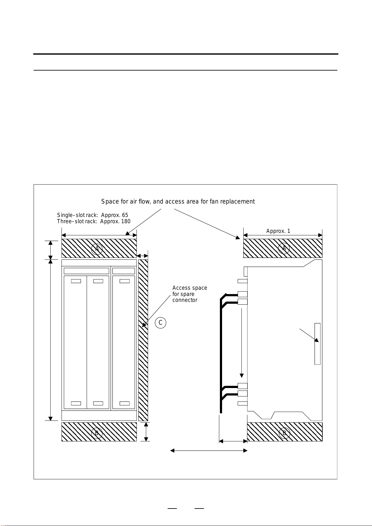
7169Fr4Hqa2ECQqEpRfd63ND/4NVqYNEFOTqTAv7RCUlwWzsC+2wd68VWEg==
3. INSTALLATION
3.6.2
Installing the
Stand–alone T ype
Control Unit
Single–slot rack: Approx. 65
Three–slot rack: Approx. 180
B–63523EN/03
The control unit is equipped with a fan motor.
Air is fed into the bottom of the unit and output from the fan motor
mounted on the top of the unit.
The spaces shown in Fig. 3.6.2 (areas (A) and (B)) are always required to
ensure smooth air flow.
Also, adequate service access space is required in front of and at the top
of the unit so that printed circuit boards and the fan motor can be replaced
easily if necessary.
There is a spare connector located at the far end (at middle height) on the
right side of the control unit. This connector is used for controller testing
and other purposes. Therefore, space (area (C)) for handling the
connector is required.
Space for air flow, and access area for fan replacement
Approx. 180
50380
A
30
Access space
for spare
connector
C
Spare connector
A
B B
© MyFANUC 19C934977F3A4E20A8A35A328E753C6E
50
80
Sufficient space for
replacing a printed circuit
board is required.
Fig. 3.6.2
54
Unit: mm
Page 71

7169Fr4Hqa2ECQqEpRfd63ND/4NVqYNEFOTqTAv7RCUlwWzsC+2wd68VWEg==
B–63523EN/03
3.7
CABLING DIAGRAM
3.8
DUSTPROOF MEASURES FOR CABINETS AND PENDANT BOXES
3. INSTALLATION
For the cabling diagram, see the control unit configuration and
component names in Section 1.1.
The cabinet and pendant box that house a display and a operator’s panel
that are to be designed and manufactured by the machine tool builder are
susceptible to dust, cutting debris, oil mist, etc. Note the following and
make sure that they are structured to prevent their entry.
1) The cabinet and pendant box must be of a hermetically sealed
structure.
2) Apply packing to the panel mounting surface to which a display and
operator’s panel are to be mounted.
3) Make sure that the door packing of the cabinet and pendant box is
sealed firmly.
4) For a cabinet or pendant box with a rear cover, apply packing to the
mounting surface.
5) Make sure that the cable entrance is sealed with packing, connectors
for conduits, etc.
6) Make sure that all other openings are blocked, if any.
7) Make sure that the display and operator’s panel do not receive cutting
debris and coolant directly.
8) Oil can easily stay on the top of the cabinet and pendant box, possibly
dripping down the display and operator’s panel. Make sure that the
cabinet and pendant box is of such a structure that oil do not collect
or that oil do not drip down the display or panel.
Panel (display/
operator’s panel)
If the frame is weak, reinforce it.
Cable entrance (example)
Hardware
Cable
Packing
Cabinet/pendant box
Connector for conduit
Cable
Panel (rear cover)
Apply packing.
Beware of collection of oil.
Oil must not collect or drip.
Display/
operator’s
panel
55
© MyFANUC 19C934977F3A4E20A8A35A328E753C6E
Page 72

7169Fr4Hqa2ECQqEpRfd63ND/4NVqYNEFOTqTAv7RCUlwWzsC+2wd68VWEg==
4. POWER SUPPLY CONNECTION
POWER SUPPLY CONNECTION
4
B–63523EN/03
56
© MyFANUC 19C934977F3A4E20A8A35A328E753C6E
Page 73

7169Fr4Hqa2ECQqEpRfd63ND/4NVqYNEFOTqTAv7RCUlwWzsC+2wd68VWEg==
B–63523EN/03
4.1
GENERAL
4. POWER SUPPLY CONNECTION
This section explains the connection of power supply for i Series control
unit.
57
© MyFANUC 19C934977F3A4E20A8A35A328E753C6E
Page 74

7169Fr4Hqa2ECQqEpRfd63ND/4NVqYNEFOTqTAv7RCUlwWzsC+2wd68VWEg==
4. POWER SUPPLY CONNECTION
4.2
TURNING ON AND OFF THE POWER TO THE CONTROL UNIT
4.2.1
Power Supply for the Control Unit
B–63523EN/03
Supply power (24VDC) to the control uint of i series CNC from an
external sources.
Provide ON/OFF circuit A for turning the AC power on and off or
ON/OFF circuit B for turning 24 VDC on and off outside the unit as
shown in Fig. 4.2.1 (a). It is recommended that the AC power be turned
on and off (ON/OFF circuit A).
When the i series CNC with PC functions is used, apply countermeasures
to guard against the possible destruction of hard disk storage due to
momentary power failure or power outage, by installing an
uninterruptible power supply, etc.
See Section 3.2 for power capacity.
Main circuit
breaker
200 V AC
Magnetic
contractor
AC line
filter
Servo converter Servo inverter
3–phase 200 V
AC for power
line
Single–phase
200 V AC for
control line
External 24 V
DC power
Fig. 4.2.1 (a)
ON/OFF circuit
ON OFF COM
CNC control unit
24 V DC
input
I/O units, etc.
58
© MyFANUC 19C934977F3A4E20A8A35A328E753C6E
Page 75

7169Fr4Hqa2ECQqEpRfd63ND/4NVqYNEFOTqTAv7RCUlwWzsC+2wd68VWEg==
B–63523EN/03
ON/OFF circuit (example)
+24V
DC INPUT
24 V
0V
POWER ON/OFF SWITCH
4. POWER SUPPLY CONNECTION
For example, “ON/OFF circuit” is as follows : (Fig.4.2.1 (b) )
Select the circuit devices, in consideration of its capacity.
+24V
OUTPUT 24 VDC
The power rating is the
sum of power requirements
on the load side.
0V
RELA Y CONTACT
A CONT ACT
RY1
ry1
ry1
ONCOMOFF
Fig. 4.2.1 (b)
DIODE
B
CONTACT
RELAY
COIL
59
© MyFANUC 19C934977F3A4E20A8A35A328E753C6E
Page 76

7169Fr4Hqa2ECQqEpRfd63ND/4NVqYNEFOTqTAv7RCUlwWzsC+2wd68VWEg==
4. POWER SUPPLY CONNECTION
4.2.2
+24V Input Power Specifications
B–63523EN/03
Specifications of recommended external 24 VDC power supply
(regulated power supply): (The power supply must satisfy UL1950.)
Output voltage: +24 V (10% (21.6 V to 26.4 V)
(including ripple voltage and noise. See the figure
below.)
Output current: The continuous load current must be larger than the
current consumption of the CNC.
(At the maximum temperature inside the power
magnetics cabinet in which the power supply is
located)
Load fluctuations (including rush current):
The output voltage must not go out of the above range
due to load fluctuations by external DO and other
factors.
Instantaneous input interruption retention time: 10 mS (for –100%)
20 mS (for –50%)
Instantaneous
interruption
(–100%)
Instantaneous
interruption
(–50%)
AC input voltage
26.4V
Output voltage
21.6V
Output current
10mS 20mS
Abrupt
load
change
0A
Fig. Example of ripple voltage and noise due to switching power supply
Noise
Ripple
voltage
Noise
Fig 4.2.2 (a) Timing chart
60
© MyFANUC 19C934977F3A4E20A8A35A328E753C6E
Page 77

7169Fr4Hqa2ECQqEpRfd63ND/4NVqYNEFOTqTAv7RCUlwWzsC+2wd68VWEg==
B–63523EN/03
S Notes to take when the
vertical axis exists
S Circuit configurations
Forbidden
4. POWER SUPPLY CONNECTION
When the vertical axis exists, select the DC power supply that has a long voltage
hold time to decrease the amount of vertical axis falling during power–off
(including a power failure).
If the operating voltage drops to less than or equal to 21.6V, the CNC releases
servo activation. Therefore, when the hold time for 24 VDC during AC
power–off is too short, servo activation is released before the breaks are applied
because some peripheral circuit detects power–off. This may increase the
amount of vertical axis falling.
Generally, a power supply with sufficient power capacity tends to increase the
hold time during power–off.
The following circuit configurations are not recommended.
1 Circuit examples that cannot retain the output voltage at an
instantaneous interruption (the voltage reduces to 21.6 V or below)
Example 1
AC input
Rectifier
circuit
CNC unit
Example 2
AC input
Rectifier
circuit
CNC unit
NOTE
The rectifier circuit means a circuit using diodes for
full–wave rectification.
2 Circuit examples that exceed the output voltage specifications (21.6
V to 26.4 V) due to an abrupt load change
Example 1
AC input
Regulated
power
supply
CNC unit
Device with
remarkable
load fluctuations
61
© MyFANUC 19C934977F3A4E20A8A35A328E753C6E
Page 78

7169Fr4Hqa2ECQqEpRfd63ND/4NVqYNEFOTqTAv7RCUlwWzsC+2wd68VWEg==
4. POWER SUPPLY CONNECTION
Recommended
B–63523EN/03
Example 2
AC input
Regulated
power
supply
CNC unit
Device with
large rush
current
For a circuit configuration in 2, connect another regulated power supply
to be specifically used for the device with remarkable load fluctuations
so that the CNC and other units are not affected.
If you find instructions to ”turn the power on simultaneously when or
before turning the power to the CNC on” for a unit such as a 24 VDC
power supply, turn the power to the unit simultaneously when turning on
the power to the CNC on from now on. T o turn the power to such a unit
simultaneously when turning the power to the CNC on, connecting the
unit on the same line as for the CNC as shown in Fig. 4.2.2 (b) is
recommended. (For a separate detector (scale), see Subsection 4.2.3,
”Power–on Sequence,” however.)
Turning the power to units on simultaneously when turning the power to
the CNC:
When the following power–on timing condition is satisfied, the power to
units is assumed to be turned on simultaneously when the power to the
CNC is turned on.
Power to the CNC
Power to units
(including the
Power Mate)
On
Off
On
Off
t1
t2
t1 : 200 ms Means that the power to units (including the Power
Mate) is turned on within 200 ms before the power to
the CNC is turned on.
t2 : 500 ms Means that the power to units (including the Power
Mate) is turned on within 500 ms after the power to the
CNC is turned on.
For instructions to ”turn the power off simultaneously when or after
turning the power to the CNC off” for a unit such as a 24 VDC power
supply, the power–off sequence is not changed unlike the above
power–on sequence. (Turning the power off simultaneously when
turning the power to the CNC on means that the power may be turned off
within 500 ms before the power to the CNC is turned off.)
62
© MyFANUC 19C934977F3A4E20A8A35A328E753C6E
Page 79

7169Fr4Hqa2ECQqEpRfd63ND/4NVqYNEFOTqTAv7RCUlwWzsC+2wd68VWEg==
B–63523EN/03
AC input
When on/off circuit B is connected, the
power must not be supplied to units between the 24 VDC output of the regulated power supply and input of on/off
circuit B. (This is because the condition
that the power to the units is turned on
within 200 ms before the power to the
CNC is turned on.)
On/off
circuit A
4. POWER SUPPLY CONNECTION
The following circuit configuration is recommended.
The power to the CNC and other units (F ANUC I/O Unit MODEL A (I/O
Unit–A), FANUC Servo Unit (Series with an I/O link (β amplifier with
an I/O link), and so on in the sample configuration below) is assumed to
be turned on at the same time. (The power to any unit is not assumed to
be turned on during operation or before the power to the CNC is turned
on. No unit is assumed to be connected between the 24 VDC output of
the regulated power supply and input of on/off circuit B.)
Either on/off circuit is
connected.
Regulated
power
supply
On/off
circuit B
Units
CNC
I/O Unit–A
4.2.3
Power–on Sequence
β amplifier
with an I/O link
Fig 4.2.2 (b)
Turn on the power to all the units at the same time, or in the following
sequence:
1 Power to the overall machine (200 VAC), power to the
separate detector (scale)
2 Power to slave I/O units connected via the I/O link, separate
detector interface unit, and stand–alone type LCD unit (24
VDC), servo amplifier control power supply (200 VAC)
3 Power to the CNC (24 VDC)
“Turning on the power to all the units at the same time” means completing
the power–on operations in 1 and 2 above within 500 ms of performing
power–on in 3.
As for a stand–alone LCD unit for a display link, no specific power
turn–on sequence is required.
63
© MyFANUC 19C934977F3A4E20A8A35A328E753C6E
Page 80

7169Fr4Hqa2ECQqEpRfd63ND/4NVqYNEFOTqTAv7RCUlwWzsC+2wd68VWEg==
4. POWER SUPPLY CONNECTION
4.2.4
Power–off Sequence
B–63523EN/03
As for a CNC display unit with PC functions, no specific power turn–on
sequence for the CNC control unit is required.
D If the power only to the control unit of the CNC is turned on without
turning the power to the CNC display unit with PC functions on, the
control unit of the CNC does not start up normally.
D If the power only to the CNC display unit with PC functions is turned
on without turning the power to the control unit of the CNC on
conversely, the units do not start up normally.
Turn off the power to all the units at the same time, or in the following
sequence:
1 Power to the CNC (24 VDC)
2 Power to the slave I/O units connected via the I/O link,
separate detector interface unit, and stand–alone type LCD
unit (24 VDC), servo amplifier control power supply (200
VAC), and power to any separate detector (scale)
3 Power to the overall machine (200 VAC)
“Turning off the power to all units at the same time” means completing
the power–off operations in 2 and 3 above within 500 ms before the
power–off operation described in 1 above. If the power to the units
indicated in 2 or 3 is turned off other than within 500 ms of the power in
1 being turned off, alarm information is left in the NC.
The power–off sequence for a stand–alone type LCD unit supporting the
display link and an CNC display unit with PC functions is undefined.
CAUTION
When the CNC display unit with PC functions is used, the
OS must be shut down before the power to the control unit
is turned off. Be careful not to turn off the power while the
hard disk is being accessed or before the OS has
terminated; otherwise, the hardware contents may be
destroyed.
When the power is turned off or when the power is momentarily
disconnected, motor control is disabled. Problems that may be generated
from the motor control disabled state should be handled from the
machine, as necessary.
For example, when movement along a vertical axis is controlled, a brake
should be applied to prevent falling. Usually , the brake clamps the motor
when the servo is not activated or when the motor is not turning. The
clamp is released only when the motor is turning. When servo axis control
is disabled by power–off or momentary power disconnection, the brake
usually clamps the servo motor. In this case, before the relay for clamping
operates, the controlled axis may fall. So, also consider whether the
distance the axis is likely to fall will cause a problem.
64
© MyFANUC 19C934977F3A4E20A8A35A328E753C6E
Page 81
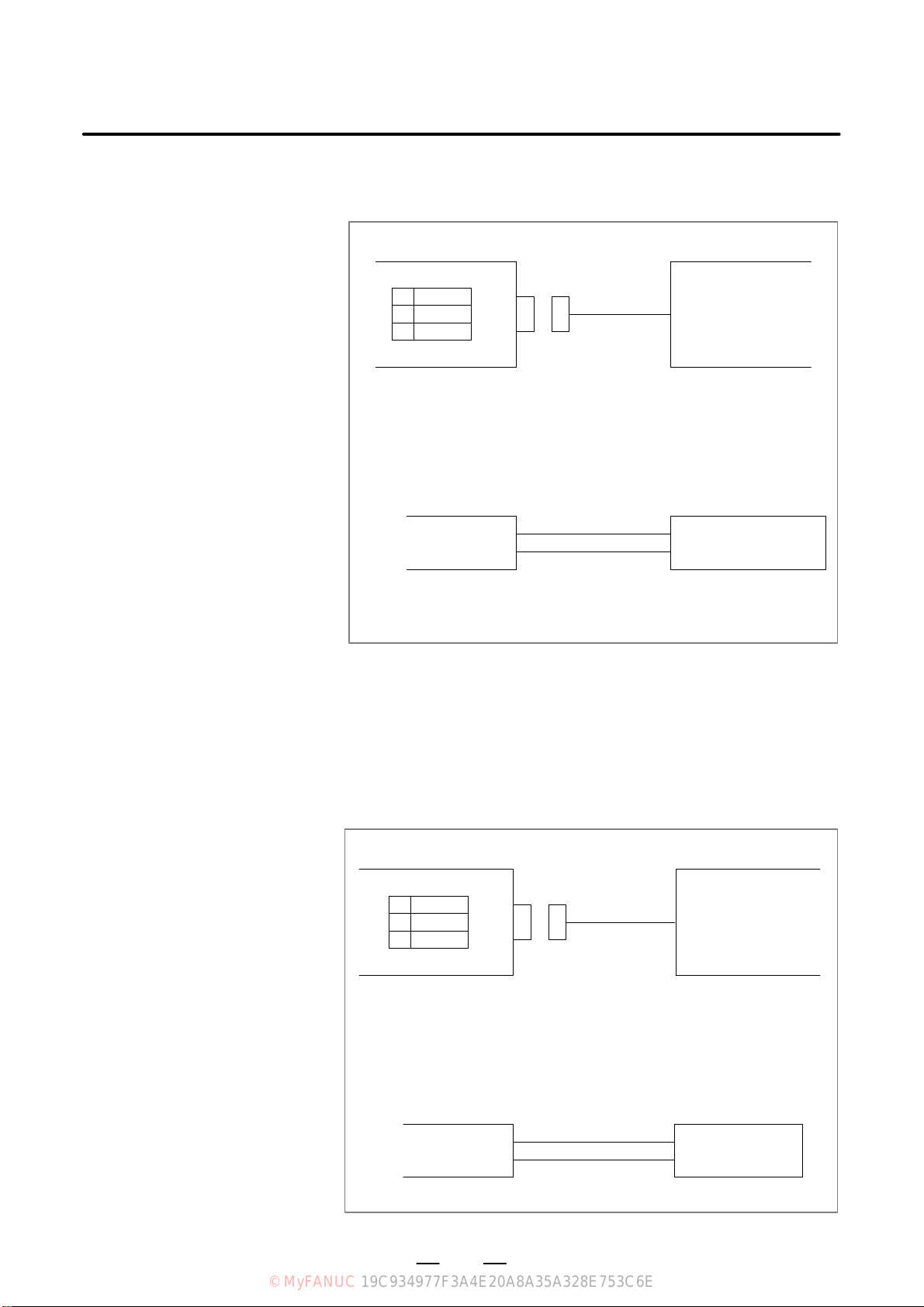
7169Fr4Hqa2ECQqEpRfd63ND/4NVqYNEFOTqTAv7RCUlwWzsC+2wd68VWEg==
B–63523EN/03
4.3
CABLE FOR POWER SUPPLY TO CONTROL UNIT
4. POWER SUPPLY CONNECTION
Supply power to the control unit from external resouce.
The brackets in the figures are the stand–alone type connector name.
i series control unit
CP1
13+24V
2
Cable
CP1A (CP1)
AMP Japan
1–178288–3 (housing)
1–175218–5 (Contact)
0V
+24V (1)
0V (2)
External power
24VDC stabilized
power
24VDC "10%
External power
Select a source that
meets the external
power terminal.
Recommended cable : A02B–0124–K830 (5m)
(Crimp terminal of size M3 is available on the external power side)
As for an stand–alone type control unit, part of the 24 VDC power input
to CP1 can be taken out from CP2 by branching. CP2 should be connected
as shown below. In this case, the rating of the external 24 VDC power
supplied to CP1 must be the sum of the power consumed within the
control unit and that supplied to external equipment via CP2. Up to 1.0
A can be supplied to the external equipment.
Series 21i/210i control unit External device
CP2
1
+24V
2
3
Cable
0V
CP2
AMP JAP AN
2–178288–3 (Housing)
1–175218–5 (Contact)
+24V (1)
0V (2)
65
© MyFANUC 19C934977F3A4E20A8A35A328E753C6E
External device
Select a connector that
matches the pin layout of
the external device.
Page 82

7169Fr4Hqa2ECQqEpRfd63ND/4NVqYNEFOTqTAv7RCUlwWzsC+2wd68VWEg==
4. POWER SUPPLY CONNECTION
4.4
BATTERIES
4.4.1
Battery for Memory Backup (3VDC)
B–63523EN/03
In a system using the i Series CNC, batteries are used as follows:
Use
Memory backup in the CNC control unit CNC control unit
BIOS data backup in the CNC display unit with
PC functions
Preservation of the current position indicated
by the separate absolute pulse coder
Preservation of the current position indicated
by the absolute pulse coder built into the motor
Component connected to
battery
CNC display unit with PC
functions
Separate detector interface
unit
Servo amplifier
Used batteries must be discarded according to appropriate local
ordinances or rules. When discarding batteries, insulate them by using
tape and so forth to prevent the battery terminals from short–circuiting.
Part programs, offset data, and system parameters are stored in CMOS
memory in the control unit. The power to the CMOS memory is backed
up by a lithium battery mounted on the front panel of the control unit. The
above data is not lost even when the main battery goes dead. The backup
battery is mounted on the control unit at shipping. This battery can
maintain the contents of memory for about a year.
When the voltage of the battery becomes low, alarm message “BAT”
blinks on the display and the battery alarm signal is output to the PMC.
When this alarm is displayed, replace the battery as soon as possible. In
general, the battery can be replaced within two or three weeks, however,
this depends on the system configuration.
If the voltage of the battery becomes any lower, memory can no longer
be backed up. T urning on the power to the control unit in this state causes
system alarm 910 (SRAM parity alarm) to occur because the contents of
memory are lost. Clear the entire memory and reenter data after replacing
the battery.
The following two kinds of batteries can be used.
D Lithium battery built into the CNC control unit.
D Two alkaline dry cells (size D) in the external battery case.
NOTE
A lithium battery is installed as standard at the factory.
66
© MyFANUC 19C934977F3A4E20A8A35A328E753C6E
Page 83

7169Fr4Hqa2ECQqEpRfd63ND/4NVqYNEFOTqTAv7RCUlwWzsC+2wd68VWEg==
B–63523EN/03
Replacing the lithium
battery
4. POWER SUPPLY CONNECTION
(1)Prepare a new lithium battery (ordering drawing number:
A02B–0200–K102).
(2)Turn the i Series on for about 30 seconds.
(3)Turn the i Series off.
(4)(LCD–mounted type i Series CNC)
Remove the old battery from the top of the CNC control unit.
First unplug the battery connector then take the battery out of its case.
The battery case of a control unit without option slots is located at the
top right end of the unit. That of a control unit with 2 slots is located
in the central area of the top of the unit (between fans).
(Stand–alone type i Series CNC)
Remove the old battery from the front panel of the CNC control unit.
First unplug the battery connector then take the battery out of its case.
(5)Insert a new battery and reconnect the connector.
NOTE
Steps (3) to (5) should be completed within the period
indicated below. Do not leave the control unit without a
battery for any longer than the period shown, as this will
result in the contents of memory being lost.
Series 16i/18i/21i: Within 30 minutes
Connector
Lithium battery
A02B–0236–K102
(LCD–mounted type i Series CNC)
WARNING
Incorrect battery replacement may cause an explosion. Do
not use a battery other than that specified (specification:
A02B–0200–K102).
Battery
case
67
© MyFANUC 19C934977F3A4E20A8A35A328E753C6E
Page 84

7169Fr4Hqa2ECQqEpRfd63ND/4NVqYNEFOTqTAv7RCUlwWzsC+2wd68VWEg==
4. POWER SUPPLY CONNECTION
Claw holding the battery
Lithium battery
B–63523EN/03
Battery connector
(Stand–alone type i Series CNC)
WARNING
Incorrect battery replacement may cause an explosion. Do
not use a battery other than that specified (specification:
A02B–0200–K102).
68
© MyFANUC 19C934977F3A4E20A8A35A328E753C6E
Page 85

7169Fr4Hqa2ECQqEpRfd63ND/4NVqYNEFOTqTAv7RCUlwWzsC+2wd68VWEg==
B–63523EN/03
Replacing the alkaline
dry cells (size D)
4. POWER SUPPLY CONNECTION
(1)Prepare two new alkaline dry cells (size D).
(2)Leave the power to the i Series CNC turned on for 30 seconds or so.
(3)Turn the i Series 16i/18i/160i/180i off.
(4)Remove the battery case cover.
(5)Replace the batteries, paying careful attention to their orientation.
(6)Replace the battery case cover.
NOTE
When replacing the dry cells, use the same procedure as
that for lithium battery replacement procedure, described
above.
Dry cell × 2
Connection terminal
on the rear
Cover
Mounting hole × 4
Battery case
69
© MyFANUC 19C934977F3A4E20A8A35A328E753C6E
Page 86

7169Fr4Hqa2ECQqEpRfd63ND/4NVqYNEFOTqTAv7RCUlwWzsC+2wd68VWEg==
4. POWER SUPPLY CONNECTION
Use of alkaline dry cells
(size D)
Connection
B–63523EN/03
Power from the external batteries is supplied through the connector to
which the lithium battery is connected. The lithium battery, provided as
standard, can be replaced with external batteries in the battery case
(A02B–0236–C281) according to the battery replacement procedures
described above.
NOTE
1 Install the battery case (A02B–0236–C281) in a location where the batteries can be replaced
even when the control unit power is on.
2 The battery cable connector is attached to the control unit by means of a simple lock system.
To prevent the connector from being disconnected due to the weight of the cable or tension
within the cable, fix the cable section within 50 cm of the connector.
70
© MyFANUC 19C934977F3A4E20A8A35A328E753C6E
Page 87

7169Fr4Hqa2ECQqEpRfd63ND/4NVqYNEFOTqTAv7RCUlwWzsC+2wd68VWEg==
B–63523EN/03
4.4.2
Batteries for CNC Display Unit with PC Functions (3VDC)
4. POWER SUPPLY CONNECTION
If the voltage of a battery drops, the screen on the LCD flashes. (If a fan
alarm is issued, the screen on the LCD also flashes.) If this status occurs,
replace the battery as soon as possible (within 1 week). FANUC
recommends that each battery be replaced periodically (once a year)
regardless of whether a battery alarm is issued.
The BIOS settings are usually preserved as long as the battery is replaced
according to the following procedure. If they are lost, the following
message is displayed when the power is turned on:
251: System CMOS checksum bad – Default configuration used.
After this, the default BIOS settings are loaded, and the unit restarts
automatically. Before starting machining, check that the current BIOS
settings of the CNC display unit with PC functions in use have been
changed from the default BIOS settings, and resume your settings as
required.
(1)After keeping the CNC display unit with PC functions powered for at
least 5 seconds, turn it off, and enable work to be done from the rear ,
for example, by removing the battery section from the panel.
(2)Remove the connector from the lithium battery, and take the battery
out from the battery holder.
(3)Attach the connector (BAT1) to a new battery within 5 minutes, and
put the battery in the battery holder.
(4) Put the CNC display unit with PC functions back into the previous
place.
(5)Turn the power on, and check that no BIOS parameter is lost (no error
is detected at start–up).
NOTE
Be sure to install a new battery within 5 minutes after the old
one is removed from the connector.
71
© MyFANUC 19C934977F3A4E20A8A35A328E753C6E
Page 88

7169Fr4Hqa2ECQqEpRfd63ND/4NVqYNEFOTqTAv7RCUlwWzsC+2wd68VWEg==
4. POWER SUPPLY CONNECTION
Lithium battery
A02B–0200–K102
Connector
(BAT1)
B–63523EN/03
Battery holder
4.4.3
Battery for Separate Absolute Pulse Coders (6VDC)
Fig.4.4.2 Battery replacement
One battery unit can maintain current position data for six absolute pulse
coders for a year.
When the voltage of the battery becomes low , APC alarms 3n6 to 3n8 (n:
axis number) are displayed on the LCD display. When APC alarm 3n7
is displayed, replace the battery as soon as possible. In general, the battery
should be replaced within one or two weeks, however , this depends on the
number of pulse coders used.
If the voltage of the battery becomes any lower, the current positions for
the pulse coders can no longer be maintained. Turning on the power to
the control unit in this state causes APC alarm 3n0 (reference position
return request alarm) to occur. Return the tool to the reference position
after replacing the battery.
Therefore, FANUC recommends that the battery be replaced once a year
regardless of whether APC alarms are generated.
See Section 7.1.3 for details of connecting the battery to separate absolute
pulse coders.
72
© MyFANUC 19C934977F3A4E20A8A35A328E753C6E
Page 89

7169Fr4Hqa2ECQqEpRfd63ND/4NVqYNEFOTqTAv7RCUlwWzsC+2wd68VWEg==
B–63523EN/03
Replacing batteries
4. POWER SUPPLY CONNECTION
Obtain four commercially available alkaline batteries (size D).
(1)Turn on the power to the machine (i Series CNC).
(2)Loosen the screws of the battery case, and remove the cover.
(3)Replace the dry batteries in the case.
Note the polarity of the batteries as shown in the figure below (orient
two batteries one way and the other two in the opposite direction).
Screws
Cover
4.4.4
Battery for Absolute Pulse Coder Built into the Motor (6VDC)
(4)After installing the new batteries, replace the cover.
(5)Turn off the power to the machine (i Series CNC).
WARNING
If the batteries are installed incorrectly, an explosion may
occur. Never use batteries other than the specified type
(Size D alkaline batteries).
CAUTION
Replace batteries while the power to the i Series CNC is on.
Note that, if batteries are replaced while no power is
supplied to the CNC, the recorded absolute position is lost.
The battery for the absolute pulse coder built into the motor is installed
in the servo amplifier. For how to connect and replace the battery, refer
to the following manuals:
D FANUC SERVO MOTOR αi series Maintenance Manual
D FANUC SERVO MOTOR β series Maintenance Manual
D FANUC SERVO MOTOR β series (I/O Link Option) Maintenance
Manual
73
© MyFANUC 19C934977F3A4E20A8A35A328E753C6E
Page 90

7169Fr4Hqa2ECQqEpRfd63ND/4NVqYNEFOTqTAv7RCUlwWzsC+2wd68VWEg==
5. CONNECTION TO CNC PERIPHERALS
CONNECTION TO CNC PERIPHERALS
5
B–63523EN/03
74
© MyFANUC 19C934977F3A4E20A8A35A328E753C6E
Page 91

7169Fr4Hqa2ECQqEpRfd63ND/4NVqYNEFOTqTAv7RCUlwWzsC+2wd68VWEg==
B–63523EN/03
5.1
CONNECTION OF
MDI UNIT
(LCD–MOUNTED
TYPE)
5.1.1
General
5. CONNECTION TO CNC PERIPHERALS
“MDI unit” is the generic name used to refer to a manual data input device.
It has a keyboard and is used to input CNC data such as programs and
parameters into the CNC.
A standard MDI unit is available for each of the i Series models with
personal computer function according to the specifications.
75
© MyFANUC 19C934977F3A4E20A8A35A328E753C6E
Page 92

7169Fr4Hqa2ECQqEpRfd63ND/4NVqYNEFOTqTAv7RCUlwWzsC+2wd68VWEg==
5. CONNECTION TO CNC PERIPHERALS
5.1.2
Connection to the MDI
Unit (LCD–mounted
Type)
B–63523EN/03
CN2
MDI
CA55
MDI cable
Soft key flexible cable
Included in the main unit
CK1
MDI unit
76
© MyFANUC 19C934977F3A4E20A8A35A328E753C6E
Page 93

7169Fr4Hqa2ECQqEpRfd63ND/4NVqYNEFOTqTAv7RCUlwWzsC+2wd68VWEg==
B–63523EN/03
5.1.3
Connection with the Standard MDI Unit
CNC
CA55
JAE LY20–20P–DTI–P
P
1
2
3
*KEY04
*KEY05
4
*COM005
6
*COM01
*COM047 *COM06
8
*COM05 *COM07
*COM089
*COM09
10 *COM11
Recommended cable specification:
A02B–0236–K812 (25 cm)
A02B–0236–K813 (45 cm)
Recommended wire specification:
A66L–0001–0284#10P (#28AWG × 10 pairs)
BA
*KEY02*KEY00
*KEY03*KEY01
*KEY06
*KEY07
*COM02
*COM03
*COM10
*KEY00
*KEY02
*KEY01
*KEY03
*KEY04
*KEY06
*KEY05
*KEY07
*COM00
*COM02
*COM01
*COM03
*COM04
*COM06
*COM05
*COM07
*COM08
*COM10
*COM09
*COM11
CA55
Japan Aviation Electronics
LY10–DC20 (Housing)
LY10–C2–3 (Contact)
A02B–0236–K303
A1
B1
A2
B2
A3
B3
A4
B4
A5
B5
A6
B6
A7
B7
A8
B8
A9
B9
A10
B10
SHIELD
5. CONNECTION TO CNC PERIPHERALS
MDI unit
CK1
PCR–E20MDK–SL–A
*KEY00
1
*KEY02
2
*KEY04
3
*KEY064 *KEY07
*COM005 *COM01
*COM026 *COM03
*COM047
*COM068
*COM089 *COM09
10
*COM10
CK1
1
*KEY00
2
*KEY02
11
*KEY01
12
*KEY03
3
*KEY04
4
*KEY06
13
*KEY05
14
*KEY07
5
*COM00
6
*COM02
15
*COM01
16
*COM03
7
*COM04
8
*COM06
17
*COM05
18
*COM07
9
*COM08
10
*COM10
19
*COM09
20
*COM11
GROUNDING PLA TE
11
12
13
14
15
16
17
18
19
*KEY01
*KEY03
*KEY05
*COM05
*COM07
*COM1120
NOTE
For MDI cable connector mating on the CA55 side, a simple lock mechanism is employed.
Ensure that a load greater than 1 kg is not applied to the connectors. Moreover , clamp the cable
so that excessive force is not applied due to vibration. However, shielding and clamping are
not required for a cable of up to 50 cm.
77
© MyFANUC 19C934977F3A4E20A8A35A328E753C6E
Page 94

7169Fr4Hqa2ECQqEpRfd63ND/4NVqYNEFOTqTAv7RCUlwWzsC+2wd68VWEg==
5. CONNECTION TO CNC PERIPHERALS
5.1.4
Key Layout of
Separate–type MDI
Compact keys for lathe
series (T series)
English display
B–63523EN/03
Symbol display
78
© MyFANUC 19C934977F3A4E20A8A35A328E753C6E
Page 95

7169Fr4Hqa2ECQqEpRfd63ND/4NVqYNEFOTqTAv7RCUlwWzsC+2wd68VWEg==
B–63523EN/03
Compact keys for
machine center series
(M series)
English display
5. CONNECTION TO CNC PERIPHERALS
Symbol display
79
© MyFANUC 19C934977F3A4E20A8A35A328E753C6E
Page 96

7169Fr4Hqa2ECQqEpRfd63ND/4NVqYNEFOTqTAv7RCUlwWzsC+2wd68VWEg==
5. CONNECTION TO CNC PERIPHERALS
Standard keys for lathe
series (T series)
English display
B–63523EN/03
Symbol display
80
© MyFANUC 19C934977F3A4E20A8A35A328E753C6E
Page 97

7169Fr4Hqa2ECQqEpRfd63ND/4NVqYNEFOTqTAv7RCUlwWzsC+2wd68VWEg==
B–63523EN/03
Compact keys for
machining center series
(M series)
English display
5. CONNECTION TO CNC PERIPHERALS
Symbol display
81
© MyFANUC 19C934977F3A4E20A8A35A328E753C6E
Page 98

7169Fr4Hqa2ECQqEpRfd63ND/4NVqYNEFOTqTAv7RCUlwWzsC+2wd68VWEg==
5. CONNECTION TO CNC PERIPHERALS
5.1.5
61–Key MDI Unit
The 61–key MDI unit can be used, in addition to the conventional MDI
units (small MDI unit and standard MDI unit). On this 61–key MDI unit,
the alphabetic keys are each assigned to a single letter, and are arranged
in alphabetical order.
(1)Connection
The 61–key MDI unit can be connected in the same way as the small
and standard MDI units. See Subsection 5.1.3.
The 61–key MDI unit cannot, however, be detached. The CNC control
unit automatically determines whether a 61–key MDI unit or a
conventional MDI unit is attached when the control unit is turned on.
If a 61–key MDI unit is connected after the control unit is turned on,
therefore, the keys cannot be recognized correctly.
(2)Outline drawing
An outline drawing is given in Appendix A.
B–63523EN/03
82
© MyFANUC 19C934977F3A4E20A8A35A328E753C6E
Page 99

7169Fr4Hqa2ECQqEpRfd63ND/4NVqYNEFOTqTAv7RCUlwWzsC+2wd68VWEg==
B–63523EN/03
5.2
CONNECTION WITH
THE DISPLAY/MDI
UNITS (FOR THE
STAND–ALONE TYPE
i SERIES CNC)
5.2.1
Overview
Connection with a 10.4″ LCD unit or 9.5″ LCD unit
Control
unit
With the stand–alone type i Series CNC (except CNC with the PC
functions), the following display/MDI units can be connected:
5. CONNECTION TO CNC PERIPHERALS
LCD Unit MDI Unit
Connection with a 7.2″ LCD unit via the display link
MDI Unit
Control
unit
When an LCD/MDI integration unit is used, the connections within the dotted box ( )
are completed inside the unit.
Connection with a detachable 7.2″ LCD unit via the display link
VIDEO
Soft key cable
24VDC
24VDC
LCD Unit
24VDC
Control
unit
24VDC
© MyFANUC 19C934977F3A4E20A8A35A328E753C6E
Branch
connector
83
Detachable LCD/
MDI unit
Page 100

7169Fr4Hqa2ECQqEpRfd63ND/4NVqYNEFOTqTAv7RCUlwWzsC+2wd68VWEg==
5. CONNECTION TO CNC PERIPHERALS
Connection with an CNC display unit with PC functions
Control
unit
MDI Unit
5.2.2
Connection with the
10.4″/9.5″ LCD Unit
CNC display
unit with PC
functions
B–63523EN/03
FA full
keyboard
24VDC
Control unit
Optical fiber cable
COP20A COP20B
External power
supply
24 VDC ±10%
LCD Unit
CP1A
CP1B
CA55
MDI Unit
84
© MyFANUC 19C934977F3A4E20A8A35A328E753C6E
CK1
 Loading...