

Epson TM-T20III Technical Reference Guide
Technical Reference Guide
Product Overview
Describes features of the product.
Setup
Describes setup and installation of the product and peripherals.
Advanced Usage
Describes advanced usage methods for the product.
Application Development Information
Describes how to control the printer and necessary information when you develop applications.
Handling
Describes how to handle the product.
Replacement of the TM-T20II
Describes precautions for replacement.
Appendix
Describes general specifications and character code tables.
M00122203
Rev. D

Cautions
•No part of this document may be reproduced, stored in a retrieval system, or transmitted in any form or by any means, electronic, mechanical, photocopying, recording, or otherwise, without the prior written permission of Seiko Epson Corporation.
•The contents of this document are subject to change without notice. Please contact us for the latest information.
•While every precaution has been taken in the preparation of this document, Seiko Epson Corporation assumes no responsibility for errors or omissions.
•Neither is any liability assumed for damages resulting from the use of the information contained herein.
•Neither Seiko Epson Corporation nor its affiliates shall be liable to the purchaser of this product or third parties for damages, losses, costs, or expenses incurred by the purchaser or third parties as a result of: accident, misuse, or abuse of this product or unauthorized modifications, repairs, or alterations to this product, or (excluding the U.S.) failure to strictly comply with Seiko Epson Corporation's operating and maintenance instructions.
•Seiko Epson Corporation shall not be liable against any damages or problems arising from the use of any options or any consumable products other than those designated as Original Epson Products or Epson Approved Products by Seiko Epson Corporation.
Trademarks
EPSON is a registered trademark of Seiko Epson Corporation. Exceed Your Vision and ESC/POS are registered trademarks or trademarks of Seiko Epson Corporation.
Microsoft and Windows are registered trademarks of Microsoft Corporation in the United States and/or other countries.
Wi-Fi→, WPA™, and WPA2™ are either registered trademarks or trademarks of Wi-Fi Alliance→.
IOS is a trademark or registered trademark of Cisco in the U.S. and other countries and is used under license. Android™ is a trademark of Google LLC.
Google Play and the Google Play logo are trademarks of Google LLC.
All other trademarks are the property of their respective owners and used for identification purpose only.
ESC/POS→ Command System
EPSON ESC/POS is a proprietary POS printer command system that includes patented or patent-pending commands. ESC/POS is compatible with most EPSON POS printers and displays. ESC/POS is designed to reduce the processing load on the host computer in POS environments. It comprises a set of highly functional and efficient commands and also offers the flexibility to easily make future upgrades.
©Seiko Epson Corporation 2019-2021.

For Safety
Key to Symbols
The symbols in this manual are identified by their level of importance, as defined below. Read the following carefully before handling the product.
You must follow warnings carefully to avoid serious bodily injury.
WARNING
|
Provides information that must be observed to prevent damage to the equipment or loss of data. |
|
|
• Possibility of sustaining physical injuries. |
|
CAUTION |
• Possibility of causing physical damage. |
|
• Possibility of causing information loss. |
||
|
Provides information that must be observed to avoid damage to your equipment or a malfunction.
Provides important information and useful tips.
Warnings
|
• |
To avoid risk of electric shock, do not set up this product or handle cables during a |
|
|
thunderstorm |
WARNING |
• |
Never insert or disconnect the power plug with wet hands. |
|
Doing so may result in severe shock. |
|
|
|
•Handle the power cable with care.
Improper handling may lead to fire or electric shock.
Do not modify or attempt to repair the cable.
Do not place any heavy object on top of the cable.
Avoid excessive bending, twisting, and pulling.
Do not place the cable near heating equipment.
Check that the plug is clean before plugging it in.
Be sure to push the plug all the way in.
•Be sure to use the specified AC adapter.
Connection to an improper power source may cause fire or shock.
•Do not place multiple loads on the power outlet. Overloading the outlet may lead to fire.
•Shut down your equipment immediately if it produces smoke, a strange odor, or unusual noise. Continued use may lead to fire. Immediately unplug the equipment and contact qualified service personnel.
•Never attempt to repair this product yourself. Improper repair work can be dangerous.
•Never disassemble or modify this product.
Tampering with this product may result in injury or fire.
•Do not allow foreign matter to fall into the equipment. Penetration by foreign objects may lead to fire.
3

• If water or other liquid spills into this equipment, do not continue to use it.
|
Continued use may lead to fire. Unplug the power cord immediately and contact qualified |
|
WARNING |
service personnel. |
|
• Do not use aerosol sprayers containing flammable gas inside or around this product. |
||
|
||
|
Doing so may cause fire. |
Cautions
|
• |
Do not connect cables in ways other than those mentioned in this manual. |
|
|
Different connections may cause equipment damage or fire. |
CAUTION |
• |
Be sure to set this equipment on a firm, stable, horizontal surface. |
|
The product may break or cause injury if it falls. |
|
|
|
•Do not use this product in locations subject to high humidity or dust levels. Excessive humidity and dust may cause equipment damage or fire.
•Do not place heavy objects on top of this product. Never stand or lean on this product. Equipment may fall or collapse, causing breakage and possible injury.
•Take care not to push your hand or finger against the manual cutter. Doing so may injure your hand or finger.
When you remove printed paper
When you perform other operations such as loading/replacing roll paper
•Do not open the roll paper cover without taking the necessary precautions, as this can result in injury from the autocutter fixed blade.
•To ensure safety, unplug this product before leaving it unused for an extended period.
•Do not remove the user interface board installed on this product.
Caution Labels
The caution labels on the product indicate the following precautions.

 CAUTION:
Do not touch the thermal head and the frame on its side during or immediately after use. After printing, the thermal head and its surroundings can be very hot.
Restriction of Use
When this product is used for applications requiring high reliability/safety, such as transportation devices related to aviation, rail, marine, automotive, etc.; disaster prevention devices; various safety devices, etc.; or functional/precision devices, etc., you should use this product only after giving consideration to including failsafes and redundancies into your design to maintain safety and total system reliability.
Because this product was not intended for use in applications requiring extremely high reliability/safety, such as aerospace equipment, main communication equipment, nuclear power control equipment, or medical equipment related to direct medical care, etc., please make your own judgment on this product's suitability after a full evaluation.
4

Note About Interference
•This product generates, uses, and can radiate radio frequency energy and, if not installed and used in accordance with the instruction manual, may cause harmful interference to radio communications.
•If this equipment does cause harmful interference to radio or television reception, which can be determined by turning the equipment off and on, the user is encouraged to try to correct the interference by one or more of the following measures:
-Reorient or relocate the receiving antenna for the radio/TV.
-Increase the separation between the equipment and the radio/TV.
-Connect the equipment into an outlet on a circuit different from that to which the receiver is connected.
-Consult your dealer or an experienced radio/TV technician for help.
•Never disassemble or modify this product.
•Seiko Epson Corporation shall not be liable for interference to radio/TV resulting from changes or modifications to this product not expressly approved by Seiko Epson Corporation.
Open Source Software License
This product uses open source software in addition to Epson proprietary software. For information of the open source software used in this product, see the following URL.
http://xxx.xxx.xxx.xxx/licenses.html
For “xxx.xxx.xxx.xxx” in the above URL, input your printer’s IP address.
5

About this Manual
Aim of the Manual
This manual provides developers/engineers with all the necessary information for design, development and installation of a POS system, and also design and development of a printer application.
Manual Content
The manual is made up of the following sections:
Chapter 1 |
Product Overview |
|
Chapter 2 |
Setup |
|
Chapter 3 |
Advanced Usage |
|
Chapter 4 |
Application Development Information |
|
Chapter 5 |
Handling |
|
Chapter 6 |
Replacement of the TM-T20II |
|
Appendix |
Product Specifications |
|
Specifications of Interfaces and Connectors |
||
|
6

Contents |
|
■ For Safety.................................................................................................................................. |
3 |
Key to Symbols.................................................................................................................................................................. |
3 |
Warnings ............................................................................................................................................................................. |
3 |
Cautions............................................................................................................................................................................... |
4 |
■ Caution Labels ......................................................................................................................... |
4 |
■ Restriction of Use .................................................................................................................... |
4 |
■ Note About Interference........................................................................................................ |
5 |
Open Source Software License ................................................................................................................................... |
5 |
■ About this Manual .................................................................................................................. |
6 |
Aim of the Manual ........................................................................................................................................................... |
6 |
Manual Content................................................................................................................................................................ |
6 |
■ Contents.................................................................................................................................... |
7 |
Product Overview .......................................................................................... |
11 |
■ Features ................................................................................................................................. |
11 |
■ Product Configurations ...................................................................................................... |
12 |
Models................................................................................................................................................................................ |
12 |
Accessories ....................................................................................................................................................................... |
12 |
■ Parts and Functions ............................................................................................................. |
13 |
LED lights .......................................................................................................................................................................... |
14 |
Connectors ....................................................................................................................................................................... |
15 |
■ Status and Errors .................................................................................................................. |
16 |
Online and Offline.......................................................................................................................................................... |
16 |
Automatically Recoverable Errors ............................................................................................................................ |
16 |
Recoverable Errors......................................................................................................................................................... |
17 |
Unrecoverable Errors .................................................................................................................................................... |
17 |
Status Display .................................................................................................................................................................. |
18 |
■ NV Memory ........................................................................................................................... |
19 |
NV Graphics Memory.................................................................................................................................................... |
19 |
User NV Memory ............................................................................................................................................................ |
19 |
Memory Switches (Customized Value) ................................................................................................................... |
19 |
R/E (Receipt Enhancement)........................................................................................................................................ |
19 |
User-defined Page ......................................................................................................................................................... |
20 |
Maintenance Counter................................................................................................................................................... |
20 |
■ Simple Setup for Wireless LAN .......................................................................................... |
21 |
■ Useful Functions for Smart Devices.................................................................................. |
22 |
QR Code............................................................................................................................................................................. |
22 |
7

Setup ............................................................................................................... |
23 |
■ Flow of Setup ........................................................................................................................ |
23 |
■ Installing the Printer............................................................................................................ |
24 |
Installing the Printer Vertically .................................................................................................................................. |
24 |
Hanging the Printer on a Wall.................................................................................................................................... |
25 |
■ Adjusting the Roll Paper Near-End Sensor...................................................................... |
27 |
■ Connecting the AC adapter................................................................................................ |
28 |
Connecting Procedure ................................................................................................................................................. |
28 |
■ Connecting the Printer to the Host................................................................................... |
29 |
USB Interface ................................................................................................................................................................... |
29 |
Serial Interface ................................................................................................................................................................ |
29 |
Ethernet Interface .......................................................................................................................................................... |
30 |
Wireless LAN Interface (when OT-WL06 is used) ................................................................................................ |
31 |
■ Connecting the Cash Drawer ............................................................................................. |
35 |
Cash Drawer Requirements........................................................................................................................................ |
35 |
Connecting the Drawer Kick Cable.......................................................................................................................... |
36 |
■ Connecting the Optional External Buzzer....................................................................... |
37 |
Connecting Procedure ................................................................................................................................................. |
37 |
■ Connecting the Optional Wireless LAN Unit................................................................... |
39 |
■ Attaching the Power Switch Cover ................................................................................... |
40 |
■ Changing the Paper Width ................................................................................................. |
41 |
Advanced Usage ............................................................................................ |
42 |
■ Software Settings................................................................................................................. |
42 |
Feature ............................................................................................................................................................................... |
43 |
■ Setting/Checking Modes .................................................................................................... |
51 |
Self-test Mode ................................................................................................................................................................. |
53 |
NV Graphics Information Print Mode...................................................................................................................... |
53 |
Receipt Enhancement Information Print Mode .................................................................................................. |
54 |
Software Setting Mode ................................................................................................................................................ |
54 |
Restore Default Values Mode..................................................................................................................................... |
56 |
Interface Setup Mode................................................................................................................................................... |
57 |
Peripheral Device Information Print Mode ........................................................................................................... |
58 |
Hexadecimal Dumping Mode ................................................................................................................................... |
59 |
■ Printing a Status Sheet........................................................................................................ |
60 |
■ Resetting the Interface Settings ....................................................................................... |
62 |
8

Application Development Information....................................................... |
63 |
■ Controlling the Printer ........................................................................................................ |
63 |
ePOS-Print XML............................................................................................................................................................... |
63 |
ESC/POS............................................................................................................................................................................. |
63 |
■ Controlling the Cash Drawer.............................................................................................. |
64 |
■ Controlling the Optional External Buzzer ....................................................................... |
65 |
■ Software................................................................................................................................. |
66 |
Development Kits .......................................................................................................................................................... |
66 |
Drivers ................................................................................................................................................................................ |
67 |
Utilities ............................................................................................................................................................................... |
68 |
Others................................................................................................................................................................................. |
68 |
Download ......................................................................................................................................................................... |
68 |
■ Notes on Printing Barcodes and Two-dimensional Symbols....................................... |
69 |
Handling ......................................................................................................... |
70 |
■ Installing and Replacing Roll Paper.................................................................................. |
70 |
■ Removing Jammed Paper .................................................................................................. |
72 |
When the Roll Paper Cover Cannot be Opened.................................................................................................. |
72 |
■ Cleaning the Printer............................................................................................................. |
74 |
Cleaning the Printer Case............................................................................................................................................ |
74 |
Cleaning the Thermal Head/Platen Roller............................................................................................................. |
74 |
■ Preparing for Transport....................................................................................................... |
75 |
Replacement of the TM-T20II........................................................................ |
76 |
■ Compatibility ........................................................................................................................ |
76 |
Printing .............................................................................................................................................................................. |
76 |
Print Speed ....................................................................................................................................................................... |
76 |
Logo Registration........................................................................................................................................................... |
76 |
Driver Compatibility...................................................................................................................................................... |
76 |
If Connecting as a Peripheral Device of the TM-i/DT Printer .......................................................................... |
76 |
Overall Dimensions ....................................................................................................................................................... |
77 |
Appendix......................................................................................................... |
78 |
■ Product Specifications ........................................................................................................ |
78 |
Printing Specifications ................................................................................................................................................. |
79 |
Character Specifications .............................................................................................................................................. |
80 |
Paper Specifications...................................................................................................................................................... |
81 |
Printable Area.................................................................................................................................................................. |
82 |
9

Printing and Cutting Positions .................................................................................................................................. |
84 |
Electrical Characteristics.............................................................................................................................................. |
85 |
Environmental Conditions.......................................................................................................................................... |
86 |
External Dimensions and Mass ................................................................................................................................. |
87 |
■ Specifications of Interfaces and Connectors .................................................................. |
88 |
USB Interface ................................................................................................................................................................... |
88 |
RS-232 Serial Interface ................................................................................................................................................. |
89 |
Ethernet Interface .......................................................................................................................................................... |
92 |
Wireless LAN Interface (when OT-WL06 is used) ................................................................................................ |
94 |
10
Chapter 1 Product Overview 
Product Overview
This chapter describes features of the product.
Features
Printing
•High speed receipt printing is possible (250 mm/s {9.84"/s} maximum).
•Switching from 80 mm {3.15"} width paper printing to 58 mm {2.28"} width paper printing is available.
Handling
Easy drop-in paper loading
Software
•Command protocol is based on the ESC/POS→ Proprietary Command System.
•Windows printer drivers, OPOS ADK, and OPOS ADK for .NET are available.
•Printing of various types of bar codes, GS1-DataBar, and two-dimensional symbols (PDF417, QR code, MaxiCode, Composite Symbology, Aztec Code, DataMatrix) is supported.
•A maintenance counter function is supported.
•Multiple languages are supported for code pages, Windows drivers, and utility software.
Interface
The interface is selectable when purchasing the product.
Environment
Paper reduction function is available.
Others
•Various installation layouts (horizontal, vertical, and wall-hanging installation) are selectable.
•Optional Wireless LAN unit and external buzzer are available.
11

Chapter 1 Product Overview 
Product Configurations
Models
•Serial (RS-232C)/USB interface model
•Ethernet interface model
Accessories
Included
•Roll paper (for operation check)
•Power switch cover
•Soft power switch cover
•Wall hanging bracket
•Rubber feet for vertical installation
•58 mm width roll paper guide
•AC adapter
•Interface cable*
•AC cable*
•User's Guide
*: Not included with some models
Options
•Affixing tape for fixing the printer (Model: DF-10)
•External buzzer (Model: OT-BZ20)
•Wireless LAN cable set (Model: OT-WL06)
12

Chapter 1 Product Overview 
Parts and Functions
1 |
Roll paper cover |
Open this cover to install/replace the roll paper. |
|
|
|
|
|
|
|
|
|
|
|
|
|
2 |
Manual cutter |
Use this cutter when you cut the roll paper manually. |
|||||
|
|
|
|
|
|
|
|
3 |
Cutter cover |
If the roll paper cover will not open due to a paper jam, open this cover and unlock the |
|||||
|
|
autocutter blade. |
|
|
|
|
|
|
|
|
|
|
|
|
|
4 |
Power switch |
Press this button to turn the printer on or off. ( |
|
|
: OFF/ |
|
: ON) |
|
|
|
|||||
|
|
||||||
|
|
|
|
|
|
|
|
5 |
Power switch cover |
Put this cover on the power switch to prevent it being operated inadvertently. |
|||||
|
|
To operate the power switch, insert an object with a pointed tip such as a ballpoint |
|||||
|
|
pen into the hole on the power switch cover. |
|
|
|
|
|
|
|
For attaching the power switch cover, see "Attaching the Power Switch Cover" on |
|||||
|
|
page 40. |
|
|
|
|
|
|
|
|
|
|
|
|
|
6 |
Status sheet button |
Press this button to print the interface status sheet, or to reset the interface settings. |
|||||
|
(Ethernet interface model |
|
|
|
|
|
|
|
only) |
|
|
|
|
|
|
|
|
|
|
|
|
|
|
7 |
Cover open lever |
Use this button to open the roll paper cover. |
|
|
|
|
|
|
|
|
|
|
|
|
|
8 |
Feed button |
Press this button to feed the roll paper by one line. Hold down this button to feed the |
|||||
|
|
roll paper continuously. |
|
|
|
|
|
|
|
|
|
|
|
|
|
9 |
LED lights |
For details on the LED lights, see "LED lights" on page 14. |
|||||
|
|
|
|
|
|
|
|
When turning off the printer without using the power switch, it is recommended to send a power-off command to the printer. If you use the power-off sequence, the latest maintenance counter values are saved. (Maintenance counter values are usually saved every two minutes.) For information about ESC/POS commands, see the ESC/POS Command Reference.
13

Chapter 1 Product Overview 
LED lights
1
2
|
|
|
3 |
|
|
|
|
1 |
Power LED |
• |
On when the power supply is on. |
|
|
• |
Off when the power supply is off. |
|
|
|
|
2 |
Error LED |
Lights or flashes when the printer is offline. (For information about the lighting and |
|
|
|
flashing patterns, see "Status and Errors" on page 16.) |
|
•Lights after the power is turned on or after a reset (offline). Automatically goes out after a while to indicate that the printer is ready.
•Lights when the end of the roll paper is detected, and when printing has stopped (offline). If this happens, replace the roll paper.
•Off when the printer is in standard mode (online).
3 |
Paper LED |
• Lights when there is no more roll paper. If the near-end detection is set to |
|
|
“Enabled”, this LED also lights when the near-end of the paper is detected. |
•Off when there is a sufficient amount of roll paper remaining.
•Flashes when a self-test is in progress or when macro execution standby state.
14

Chapter 1 Product Overview 
Connectors
All connectors are located on the lower rear of the printer.
•The interface installed differs according to the model.
•Do not remove the user interface board installed on this product.
1 |
Serial interface |
Connects the serial cable for connecting to a computer. |
|
|
|
2 |
USB (Type-B) connector |
Connects the USB cable for connecting to a computer. |
|
|
The connector is covered with a plate when shipped with some model. |
|
|
When using this connector with such model, set Interface Selection in the |
|
|
printer's Software Setting Mode to [Built-in USB]. See "Software Settings" |
|
|
on page 42. |
|
|
|
3 |
Ethernet connector |
Connects the 10BASE-T/100BASE-TX Ethernet cable. |
|
|
|
4 |
Power supply connector |
Connects the AC cable. "Connecting the AC adapter" on page 28 |
|
|
|
5 |
USB (Type-A) connector |
Use only for connecting optional Wireless LAN unit. |
|
|
Leave the cover in place if this connector is not used. |
|
|
|
6 |
Drawer kick connector |
Connects the cash drawer or the optional external buzzer. |
|
|
"Connecting the Cash Drawer" on page 35 |
|
|
"Connecting the Optional External Buzzer" on page 37 |
|
|
|
15

Chapter 1 Product Overview 
Status and Errors
The LEDs light or flash to indicate the printer status.
The printer cannot print while an error is left unsolved.
Online and Offline
Online
The printer is online and ready for normal printing unless there is a reason to go offline.
Offline
The printer automatically goes offline under the following conditions:
•While the printer power is turning on/off
•While a self-test is running
•While roll paper is fed using the Feed button
•When the printer stops printing due to a paper end
(When the paper end is detected by the roll paper end sensor)
•During an operation standby state
•When an error has occurred ("Status and Errors" on page 16)
•While the roll paper cover is open
Automatically Recoverable Errors
The printer cannot print when automatically recoverable errors occur. When the conditions for recovery described below are met, the printer automatically recovers from the error.
Error |
Error description |
Error LED status |
Condition for Recovery |
|
|
|
|
Roll paper cover |
The roll paper cover was opened |
ON |
The roll paper cover is closed |
open error |
during printing |
|
|
|
|
|
|
Head temperature error |
A high temperature outside the |
ON |
When the thermal head cools |
|
thermal head drive operating |
|
|
|
range was detected |
|
|
|
|
|
|
16
Chapter 1 Product Overview 
Recoverable Errors
The printer cannot print when a recoverable error occurs. When the roll paper cover is closed, the power is turned off and on again, or an error recovery command is received, the printer can recover from the error.
Error |
Error description |
Error LED status |
Condition for Recovery |
|
|
|
|
Autocutter error |
Autocutter does not work |
ON |
Recovers from the error when |
|
correctly |
|
the jammed paper or foreign |
|
|
|
matter is removed, and the roll |
|
|
|
paper cover is closed |
|
|
|
|
The error recovery command is valid only if a recoverable error (excluding automatically recoverable errors) occurs.
Use the TM-T20III Utility to change the condition for recovery. For details, see the TM-T20III Utility User's Manual.
Unrecoverable Errors
The printer cannot print when an unrecoverable error occurs. If the error persists after turning the printer off and then on again, the printer may be defective. Contact qualified service personnel.
Turn off the power immediately when an unrecoverable error occurs.
CAUTION
Error |
Error description |
|
Error LED flash code |
|||||||||||||||||||
|
|
|
|
|
|
|
|
|
|
|
|
|
|
|
|
|
|
|
|
|
|
|
R/W error in memory |
After R/W checking, the printer does not |
|
|
|
|
|
|
|
|
|
|
|
|
|
|
|
|
|
|
|
|
|
|
work correctly. |
|
|
|
|
|
|
|
|
|
|
|
|
|
|
|
|
|
|
|
|
|
|
|
|
|
|
|
|
|
|
|
|
|
|
|
|
|
|
|
|
|
|
|
|
High voltage error |
The power supply voltage is extremely |
|
|
|
|
|
|
|
|
|
|
|
|
|
|
|
|
|
|
|
|
|
|
high. |
LED ON |
|
|
|
|
|
|
|
|
|
|
|
|
|
|
|
|
|
|
||
|
|
|
|
|
|
|
|
|
|
|
|
|
|
|
|
|
|
|
||||
|
|
LED OFF |
|
|
|
|
|
|
|
|
|
|
|
|
|
|
|
|
|
|
|
|
Low voltage error |
The power supply voltage is extremely low. |
|||||||||||||||||||||
|
|
|
Approx. 320 ms |
|||||||||||||||||||
|
|
|
|
|||||||||||||||||||
|
|
|
|
|||||||||||||||||||
|
|
|
|
|
|
|
|
|
|
|
|
|
|
|
|
|
|
|
|
|
|
|
CPU execution error |
The CPU is executing an incorrect address. |
|
|
|
|
|
|
|
|
|
|
|
|
|
|
|
|
|
|
|
|
|
|
|
|
|
|
|
|
|
|
|
|
|
|
|
|
|
|
|
|
|
|
|
|
Internal circuit connection |
Internal circuits are not connected |
|
|
|
|
|
|
|
|
|
|
|
|
|
|
|
|
|
|
|
|
|
error |
correctly. |
|
|
|
|
|
|
|
|
|
|
|
|
|
|
|
|
|
|
|
|
|
|
|
|
|
|
|
|
|
|
|
|
|
|
|
|
|
|
|
|
|
|
|
|
17

Chapter 1 Product Overview 
Status Display
|
Power LED |
Error LED |
Paper LED |
|
|
|
|
Online |
ON |
OFF |
OFF |
|
|
|
|
Initializing after power-on |
ON |
ON |
- |
|
|
|
|
Running a self-test |
ON |
OFF |
- |
|
|
|
|
Waiting to continue self-test |
ON |
OFF |
Flashing |
|
|
|
|
Feeding using the Feed button |
ON |
OFF |
- |
|
|
|
|
Waiting to execute a macro |
ON |
OFF |
Flashing |
|
|
|
|
Roll paper cover open while the printer |
ON |
ON |
- |
is not printing |
|
|
|
|
|
|
|
No paper |
ON |
ON |
ON |
|
|
|
|
While updating firmware |
ON |
Flashing |
Flashing |
|
|
|
|
While in forced firmware update mode |
ON |
ON |
ON |
|
|
|
|
While in power off standby |
ON |
OFF |
Flashing |
|
|
|
|
The network link is down |
ON |
Flashing* |
- |
|
|
|
|
Waiting to print status sheet |
ON |
ON |
Flashing |
|
|
|
|
-: Changes depending on whether or not paper is detected.
*: The error LED flashing patterns are as follows.
LED ON 

LED OFF

 Approx. 640 ms
 Approx. 5,120 ms
18

Chapter 1 Product Overview 
NV Memory
The printer is equipped with the NV memory (Nonvolatile Memory) to store data even after the printer power is turned off. NV memory contains the following memory areas for the user:
•NV graphics memory
•User NV memory
•Memory switches (Customized value)
•R/E (Receipt Enhancement)
•User-defined page
•Maintenance counter
As a guide, NV memory rewriting should be 10 times or less a day when you program applications.
CAUTION
NV Graphics Memory
Graphics, such as shop logos to be printed on receipts, can be stored. Even with a serial interface model whose transmission speed is low, high speed graphics printing is possible.
TM-T20III Utility or ESC/POS commands can be used for the graphic registration. TM-T20III Utility or NV Graphics Information Print Mode can be used for the confirmation.
User NV Memory
You can store and read text data for multiple purposes, such as for storing a note including customizing or maintenance information of the printer.
Memory Switches (Customized Value)
You can configure various settings of the printer.
For more information, see "Software Settings" on page 42.
R/E (Receipt Enhancement)
Registered graphics in the NV Graphics Memory can be printed automatically, as a top logo before receipt printing or as a bottom logo before cutting paper.
TM-T20III Utility or ESC/POS commands can be used for the settings.
TM-T20III Utility or Receipt Enhancement Information Print Mode can be used for the confirmation.
19

Chapter 1 Product Overview 
User-defined Page
You can store character data in the user-defined page (character code table: page 255) so that you can also print characters not resident in the printer.
Maintenance Counter
With this function, printer information, such as the number of lines printed, the number of autocuts, and printer operation time after the printer starts working, is automatically stored in NV memory. You can use the counter information for periodical checks or part replacement.
• You can also check the print head running length and number of times of autocutting with the self-test (see "Self-test Mode" on page 53).
•The maintenance counter value is normally saved in the NV memory every 2 minutes (maximum of 4 minutes). However, it is not automatically saved when the product is in the power-saving mode or when the power is turned off without using the power switch.
20
Chapter 1 Product Overview 
Simple Setup for Wireless LAN
This printer comes with a mode (SimpleAP) that allows printers to connect with a smart device or a computer without requiring a wireless access point. This allows you to easily setup a wireless LAN for the printer by using a printer settings tool (TM-T20III Utility, Epson TM Utility for iOS/Android, or EpsonNet Config) even without a network environment such as access points.
SimpleAP mode is enabled by default when shipping from the factory. When SimpleAP mode is enabled and the printer is turned on, the following information is printed automatically.
SimpleAP Start |
|
SSID |
: EPSON_Printer |
Encryption Type |
: WPA2-PSK |
Passphrase |
: 12345678 |
IP Address |
: 192.168.192.168 |
MAC Address |
: xx-xx-xx-xx-xx-xx |
|
|
Although operations are performed in SimpleAP mode during the initial startup, operations switch to standard mode (infrastructure mode) when changing settings in Epson TM-T20III Utility or EpsonNet Config. After switching, operations continue in standard mode. If you want to make settings in SimpleAP mode again, initialize the communication settings. ("Resetting the Interface Settings" on page 62)
Changing to standard mode
Ex.) Change IP address,
|
|
change SSID |
||
SimpleAP mode |
|
|
|
Standard mode |
|
|
|
||
|
|
|||
|
|
|
(infrastructure |
|
(default setting) |
|
|
|
|
|
|
|
mode) |
|
|
|
|
|
|
|
|
|
|
|
|
Initialize the communication |
|||
|
settings |
|||
21

Chapter 1 Product Overview 
Useful Functions for Smart Devices
You can easily connect this product to the network by using the QR code printed on the status sheet.
QR Code
Capture the QR code printed on the status sheet with the camera on your smart device to acquire the printer information (information for specifying the device).
Specify the target printer using the acquired information to connect to the network.
• To use the function, programming using Epson ePOS SDK is required. In addition to the QR code capturing operations, use Printer Easy Select API to achieve this function.
See the “Epson ePOS SDK for Android/iOS User's Manual” and the Epson ePOS SDK sample program for more details. The sample program also contains a sample implementation method for capturing a QR code.
• You can try a demo of the function by using Epson TM Utility for iOS/Android.
22

Chapter 2 Setup 
Setup
This chapter describes setup and installation of the product and peripherals.
Flow of Setup
This chapter consists of the following sections along with the setup flow of the product and peripherals.
1.Installing the Printer (page 24)
2.Adjusting the Roll Paper Near-End Sensor (page 27)
3.Connecting the AC adapter (page 28)
4.Connecting the Printer to the Host (page 29)
5.Connecting the Cash Drawer (page 35)
6.Connecting the Optional External Buzzer (page 37)
7.Connecting the Optional Wireless LAN Unit (page 39)
8.Attaching the Power Switch Cover (page 40)
9. Changing the Paper Width (page 41)
23

Chapter 2 Setup 
Installing the Printer
You can install the printer horizontally on a flat surface (with the paper exit on top) or vertically (with the paper exit at the front). Also, you can hang it on a wall using the included accessories.
Horizontal installation |
Vertical installation |
Hanging on a wall |
•Do not place the printer in a dusty location.
•Do not knock or strike the printer. This may cause defective print.
•Do not catch cables or place foreign matter under the printer.
•Take measures to prevent the printer from moving by vibration during paper cutting and when using a drawer. Affixing tape (Model: DF-10) is provided as an option.
Installing the Printer Vertically
When installing the printer vertically, attach the four rubber feet in the rectangular indents in the printer case, as shown in the illustration below.
 Rubber feet
24

Chapter 2 Setup 
Hanging the Printer on a Wall
To securely hang the printer on a wall, follow the steps below.
•Hang the printer on a wood, concrete, or metal wall. The thickness of the wall should be 10 mm {0.4"} or more.
•Be sure to use metallic screws.
•The screws to be put into the wall must have a pull-out strength of 150 N (15.3 kgf) or more.
1 Put two screws (diameter: 4 mm {0.16"}, head diameter: 7 to 9 mm {0.28 to 0.35"}) into the wall at an interval of 80 mm {3.15"}.
Make sure the length of the screw in the wall is 10 mm {0.39"} or more, and the length outside the wall is 3 to 4 mm {0.12 to 0.16"}.
|
|
3 to 4 mm {0.12 to 0.16"} |
|
|
|
|||||||
80 mm |
7 to 9 mm |
|
|
|
|
4 mm |
||||||
|
|
|
|
|||||||||
|
|
|
|
|||||||||
{0.28 to 0.35"} |
|
|
|
|
||||||||
{3.15"} |
|
|
|
|
{0.16"} |
|||||||
|
|
|
|
|
|
|
|
|||||
|
|
|
|
|
|
|
|
|
|
|
|
|
|
|
|
|
|
|
|
|
|
|
|
|
|
|
|
|
|
|
|
|
|
|
|
|
|
|
|
|
|
|
|
|
|
|
|
|
|
|
|
|
|
|
|
|
|
|
|
|
|
|
|
|
|
|
|
|
|
|
|
|
|
|
|
|
|
10 mm {0.39"} or more
2Remove the two screws from the printer, and then attach the wall hanging bracket to the printer using the screws.
 Screws
Wall hanging bracket
25

Chapter 2 Setup 
3Align the holes in the wall hanging bracket with the screws on the wall, and hook it securely.
26

Chapter 2 Setup 
Adjusting the Roll Paper Near-End Sensor
Below are two situations where a roll paper near-end sensor adjustment is required.
•To adjust the detection position to suit the diameter of the roll paper core used.
•To adjust the detection position of remaining amount of paper.
•The roll paper near-end detection function can be used only when this product is installed horizontally.
•Be sure to disable the near-end detection when the product is installed vertically or is wallmounted. Failure to do so may lead to erroneous detection.
•Since roll paper cores vary slightly in shape, depending on paper roll design and manufacturing tolerances, it is impossible to detect the remaining paper exactly.
•Use roll paper with a core inner diameter of 12 mm {0.47"} and outer diameter of 18 mm {0.71"} so that the near-end sensor can detect the remaining paper as accurately as possible.
•To use the near-end detection, it must be enabled using the memory switches. See "Software Setting Mode" on page 54 for details about the making the memory switch settings.
Follow the steps below to adjust the roll paper near-end sensor.
1Open the roll paper cover, and remove the roll paper.
2Loosen the adjustment screw fastening the sensor, and align the upper edge of the positioning plate with the adjustment position.
Adjustment position |
Remaining amount of paper |
|
(outer diameter) |
||
|
||
|
|
|
Upper |
Approx. 27 mm {1.06"} |
|
|
|
|
Lower (Default setting) |
Approx. 23 mm {0.97"} |
|
|
|
3Tighten the adjustment screw.
4After adjustment, make sure that the detection lever operates smoothly.
 Adjustment screw
 Upper position


 Positioning plate
 Lower position
 Detection lever
27

Chapter 2 Setup 
Connecting the AC adapter
• Be sure to use the specified AC adapter [AC adapter, C1 (Model: M235B)]. Penetration by foreign objects may lead to fire.
WARNING |
• Never insert the AC cable plug into a socket that does not meet the input voltage of the AC |
|
adapter. |
||
|
||
|
Doing so may result in damage to the printer. |
|
|
• Should a fault ever occur, immediately turn off the power to the printer and unplug the AC cable |
|
|
from the wall socket. |
Connecting Procedure
1
2
Make sure the printer is turned off.
Connect the AC cable to the AC adapter.
 AC adapter
AC cable
3Connect the DC cable of the AC adapter to the power supply connector (stamped 24V).
28
Chapter 2 Setup 
Connecting the Printer to the Host
•Be sure to install the driver before connecting the printer to the host computer.
•The printer uses a modular connector specifically designed for the cash drawer. Do not connect the connector to an ordinary telephone line.
USB Interface
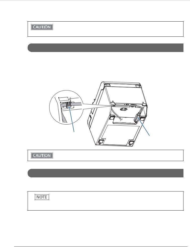
When using USB cable to connect with host device, connect the USB cable to the printer, and after starting the host device, turn the printer on.
When connecting the USB cable to the printer, fix the cable with the hook to prevent it from being disconnected.
Hooks
USB cable
Do not place any weight or stress on the cable when using. Doing so could damage the cable and connectors.
Serial Interface
When connecting to the host computer through a serial interface (RS-232), connect a serial cable to the printer, start the host computer, and then turn on the printer.
• When using connectors equipped with screws, tighten the screws on both sides to secure the connectors firmly.
•When using interface cables equipped with a ground line, attach the ground line to the screw hole marked “FG” on the printer.
29
 Loading...