

Technical Reference Guide
Describes features of the product.
Describes setup and installation of the product.
Describes advanced usage methods for the product.
Describes how to control the printer and necessary
information when you develop applications.
Describes how to handle the product.
Describes information for replacement.
Describes general specications and character code
tables.
with Peeler
Product Overview
Setup
Advanced Usage
Application Development Information
Handling
Replacement of the TM-P60
Appendix
M00060910
Rev. J

Cautions
• No part of this document may be reproduced, stored in a retrieval system, or transmitted in any form or by
any means, electronic, mechanical, photocopying, recording, or otherwise, without the prior written permission of Seiko Epson Corporation.
• The contents of this document are subject to change without notice. Please contact us for the latest information.
• While every precaution has been taken in the preparation of this document, Seiko Epson Corporation
assumes no responsibility for errors or omissions.
• Neither is any liability assumed for damages resulting from the use of the information contained herein.
• Neither Seiko Epson Corporation nor its affiliates shall be liable to the purchaser of this product or third
parties for damages, losses, costs, or expenses incurred by the purchaser or third parties as a result of:
accident, misuse, or abuse of this product or unauthorized modifications, repairs, or alterations to this
product, or (excluding the U.S.) failure to strictly comply with Seiko Epson Corporation’s operating and
maintenance instructions.
• Seiko Epson Corporation shall not be liable against any damages or problems arising from the use of any
options or any consumable products other than those designated as Original Epson Products or Epson
Approved Products by Seiko Epson Corporation.
Trademarks
EPSON is a registered trademark of Seiko Epson Corporation.
Exceed Your Vision and ESC/POS are registered trademarks or trademarks of Seiko Epson Corporation.
Microsoft
countries.
Wi-Fi
The Bluetooth® word mark and logos are registered trademarks owned by Bluetooth SIG, Inc. and any use of
such marks by Seiko Epson Corporation is under license.
IOS is a trademark or registered trademark of Cisco in the U.S. and other countries and is used under license.
Apple, Apple TV, Apple Watch, iPad, iPad Air, iPad Pro, iPhone, and Lightning are trademarks of Apple Inc.,
registered in the U.S. and other countries. tvOS is a trademark of Apple Inc.
QR Code is a registered trademark of DENSO WAVE INCORPORATED in Japan and in other countries.
Android™ is a trademark of Google LLC.
Google Play and the Google Playlogo are trademarks of Google LLC.
All other trademarks are the property of their respective owners and used for identification purpose only.
®
and Windows® are registered trademarks of Microsoft Corporation in the United States and/or other
®
, WPA™, and WPA2™ are either registered trademarks or trademarks of Wi-Fi Alliance®.
ESC/POS® Command System
Epson ESC/POS is a proprietary POS printer command system that includes patented or patent-pending
commands. ESC/POS is compatible with most Epson POS printers and displays.
ESC/POS is designed to reduce the processing load on the host computer in POS environments. It comprises a
set of highly functional and efficient commands and also offers the flexibility to easily make future upgrades.
©Seiko Epson Corporation 2013-2020. All rights reserved.
2
For Safety
Key to Symbols
The symbols in this manual are identified by their level of importance, as defined below. Read the following
carefully before handling the product.
Dangers must be observed carefully to avoid serious injury or death.
DANGER
You must follow warnings carefully to avoid serious bodily injury.
WARNING
Provides information that must be observed to prevent damage to the equipment or loss of data.
• Possibility of sustaining physical injuries.
CAUTION
• Possibility of causing physical damage.
• Possibility of causing information loss.
Provides information that must be observed to avoid damage to your equipment or a
malfunction.
Provides important information and useful tips.
Safety Precautions
Shut down your equipment immediately if it produces smoke, a strange odor, or unusual noise.
Continued use may lead to fire. Immediately unplug the equipment and contact qualified service
WARNING
personnel.
Never attempt to repair this product yourself. Improper repair work can be dangerous.
Never disassemble or modify this product. Tampering with this product may result in injury or
fire.
Be sure to use the dedicated AC adapter, Epson PS-11. Connection to an improper power supply
may cause fire.
Do not allow foreign matter to fall into the equipment. Penetration by foreign objects may lead to
fire.
If water or other liquid spills into this equipment, do not continue to use it. Continued use may
lead to fire. Unplug the equipment immediately and contact qualified service personnel.
3
Do not connect cables in ways other than those mentioned in this manual. Different connections
may cause equipment damage and burning.
CAUTION
When connecting a USB cable, do not stress the connector part. Doing so may damage that part.
Be careful not to drop this product. The product may break or cause injury if it is dropped.
Do not use in locations subject to high humidity or dust levels. Excessive humidity and dust may
cause equipment damage or fire.
Do not place heavy objects on top of this product. Never stand or lean on this product. Equipment may fall or collapse, causing breakage and possible injury.
To ensure safety, unplug this product before leaving it unused for an extended period.
Before moving the product, unplug it and unplug all cables connected to it.
Take care not to injure your fingers on the manual cutter
• When you remove printed paper
• When you perform other operations such as loading/replacing roll paper
Do not use aerosol sprayers containing flammable gas inside or around this product. Doing so
may cause fire.
Safety Precautions on the Rechargeable Battery Pack
If any liquid from the battery gets into your eyes, promptly wash it out with clean water for more
than 10 minutes and consult your doctor at once. If you do not, the liquid may cause loss of eye-
DANGER
sight.
Never disassemble or modify the battery pack. This may cause fire, explosion, leakage, overheating or damage.
Do not expose the battery to fire or heat it. This may cause fire, explosion, leakage, overheating or
damage.
WARNING
If you notice a strange odor, overheating, discoloration, distortion, or other abnormality of the
battery, remove it from the printer or charger, and do not use it. Continued use may cause overheating, fire or explosion.
Immediately move the battery pack away from fire or flame if it produces a strange odor or leakage. Leaked electrolyte may flash off, leading to fire or explosion.
Should any battery liquid get on skin or clothing, promptly wash it off with clean water. If you do
not, the liquid may damage your skin.
Do not expose the battery to water. Do not allow water to contact the terminals. This may cause
fire, overheating, or electric shock.
Be sure to use and charge the specified battery OT-BY60II. Using a battery other than the one
specified may cause fire, explosion, leakage, overheating, or other damage.
4

Restriction of Use
When this product is used for applications requiring high reliability/safety, such as transportation devices
related to aviation, rail, marine, automotive; disaster prevention devices; various safety devices; or functional/
precision devices, etc., you should use this product only after giving consideration to including fail-safes and
redundancies into your design to maintain safety and total system reliability. Because this product was not
intended for use in applications requiring extremely high reliability/safety, such as aerospace equipment, main
communication equipment, nuclear power control equipment, or medical equipment related to direct medical
care, etc., please make your own judgement on this product's suitability after a full evaluation.
Note about interference
• This product generates, uses, and can radiate radio frequency energy and, if not installed and used in accor-
dance with the instruction manual, may cause harmful interference to radio communications.
• If this equipment does cause harmful interference to radio or television reception, which can be determined
by turning the equipment off and on, the user is encouraged to try to correct the interference by one or more
of the following measures:
− Reorient or relocate the receiving antenna for the radio/TV.
− Increase the separation between the equipment and the radio/TV.
− Connect the equipment into an outlet on a circuit different from that to which the radio/TV is con-
nected.
− Consult your dealer or an experienced radio/TV technician for help.
• Never disassemble or modify this product.
• Seiko Epson Corporation shall not be liable for interference to radio/TV resulting from changes or modifica-
tions to this product not expressly approved by Seiko Epson Corporation.
5

About this Manual
Aim of the Manual
This manual was created to provide information on the development, design, and installation of POS systems
and the development and design of printer applications for developers.
Manual Content
The manual is made up of the following sections:
Chapter 1
Chapter 2
Chapter 3
Chapter 4
Chapter 5
Chapter 6
Appendix
Product Overview
Setup
Advanced Usage
Application Development Information
Handling
Replacement of the TM-P60
Product Specifications
Specifications of Interfaces and Connectors
Character Code Tables
6

Contents
Q For Safety..................................................................................................................................3
Key to Symbols.................................................................................................................................................................... 3
Safety Precautions .............................................................................................................................................................3
Safety Precautions on the Rechargeable Battery Pack .........................................................................................4
Q Restriction of Use ....................................................................................................................5
Q Note about interference ........................................................................................................5
Q About this Manual ..................................................................................................................6
Aim of the Manual ............................................................................................................................................................. 6
Manual Content .................................................................................................................................................................. 6
Q Contents....................................................................................................................................7
Product Overview ..........................................................................................11
Q Features ................................................................................................................................. 11
Q Product Configurations ...................................................................................................... 13
Interfaces.............................................................................................................................................................................13
NFC Tag................................................................................................................................................................................13
Buzzer...................................................................................................................................................................................13
Accessories .........................................................................................................................................................................13
Q Part Names and Functions ................................................................................................. 15
Control Panel .....................................................................................................................................................................15
Online and Offline............................................................................................................................................................17
Q Switching Issuing Mode...................................................................................................... 19
Q Power Functions ................................................................................................................... 20
Auto-Power Off .................................................................................................................................................................20
Battery Charge Modes....................................................................................................................................................20
Q Operation Mode When Battery is Low ............................................................................. 21
Mode 1 .................................................................................................................................................................................21
Mode 2 .................................................................................................................................................................................22
Q Error Status............................................................................................................................ 23
Automatically Recoverable Errors ..............................................................................................................................23
Recoverable Errors ...........................................................................................................................................................23
Unrecoverable Errors ......................................................................................................................................................24
Q NV Memory (Non-Volatile Memory) ................................................................................. 25
NV Graphics Memory......................................................................................................................................................25
User NV Memory ..............................................................................................................................................................25
Customized Values and Memory Switches .............................................................................................................26
User-defined Page ...........................................................................................................................................................26
Maintenance Counter.....................................................................................................................................................26
Q Useful Functions for Smart Devices.................................................................................. 27
NFC Tag................................................................................................................................................................................27
7

QR Code .............................................................................................................................................................................. 27
Setup............................................................................................................... 28
Q Flow of Setup ........................................................................................................................ 28
Q Installing the Printer............................................................................................................ 29
Notes on Using the Wi-Fi Models............................................................................................................................... 29
Q Changing the Paper Width ................................................................................................. 30
Q Installing the Battery ........................................................................................................... 32
Q Installing or Replacing the Roll Paper .............................................................................. 34
When Using the Label Continuous Issuing Mode................................................................................................ 34
When Using the Label Peeler Issuing Mode .......................................................................................................... 38
Q Connecting the Printer........................................................................................................ 42
USB Interface ..................................................................................................................................................................... 42
Wireless LAN Interface ................................................................................................................................................... 43
Bluetooth Interface......................................................................................................................................................... 44
Advanced Usage............................................................................................ 48
Q Software Settings ................................................................................................................. 48
Q Paper Layout Setting........................................................................................................... 54
Q Settings/Check Mode .......................................................................................................... 55
Self-test mode................................................................................................................................................................... 56
NV graphics information print mode ....................................................................................................................... 57
Software settings mode ................................................................................................................................................ 58
Radio field intensity check mode...............................................................................................................................60
Wireless module setup mode...................................................................................................................................... 61
Hexadecimal dumping mode ..................................................................................................................................... 65
Q Dynamic Status Sheet Print Mode .................................................................................... 66
Wi-Fi Model........................................................................................................................................................................ 66
Bluetooth Model .............................................................................................................................................................. 67
Q EpsonNet Config (Web Version) ........................................................................................ 68
Starting EpsonNet Config (Web Version)................................................................................................................ 68
Settings ............................................................................................................................................................................... 70
Application Development Information ...................................................... 73
Q Controlling the Printer ........................................................................................................ 73
ePOS-Print XML ................................................................................................................................................................ 73
ESC/POS .............................................................................................................................................................................. 73
8

Q Software and Manuals ........................................................................................................ 74
Development Kits ............................................................................................................................................................74
Drivers ..................................................................................................................................................................................75
Utilities .................................................................................................................................................................................75
Others...................................................................................................................................................................................76
Download ...........................................................................................................................................................................76
Q iOS Application Development and Distribution ............................................................ 77
Handling .........................................................................................................78
Q Charging Battery .................................................................................................................. 78
Q Cleaning the Printer............................................................................................................. 79
Cleaning the Printer Case ..............................................................................................................................................79
Cleaning the Thermal Head..........................................................................................................................................79
Cleaning the Platen Roller/Paper Sensor.................................................................................................................80
Cleaning the Peeler Unit................................................................................................................................................81
Replacement of the TM-P60 .........................................................................82
Q Compatibility ........................................................................................................................ 82
Q Additional Functions and Functional Improvements................................................... 85
Appendix.........................................................................................................86
Q Product Specifications ........................................................................................................ 86
Printing Specifications....................................................................................................................................................86
Character Specifications ................................................................................................................................................87
Paper Specifications ........................................................................................................................................................88
Printable Area....................................................................................................................................................................91
Printing and Cutting Positions ....................................................................................................................................95
Electrical Characteristics................................................................................................................................................96
Reliability.............................................................................................................................................................................97
Environmental Conditions ............................................................................................................................................98
External Dimensions and Mass ...................................................................................................................................99
Colors....................................................................................................................................................................................99
Q Specifications of Interfaces and Connectors ................................................................ 100
USB Interface .................................................................................................................................................................. 100
Wireless LAN Interface................................................................................................................................................. 101
Bluetooth Wireless Interface ..................................................................................................................................... 104
NFC Tag............................................................................................................................................................................. 108
Q Character Code Tables....................................................................................................... 109
9

10

Chapter 1 Product Overview
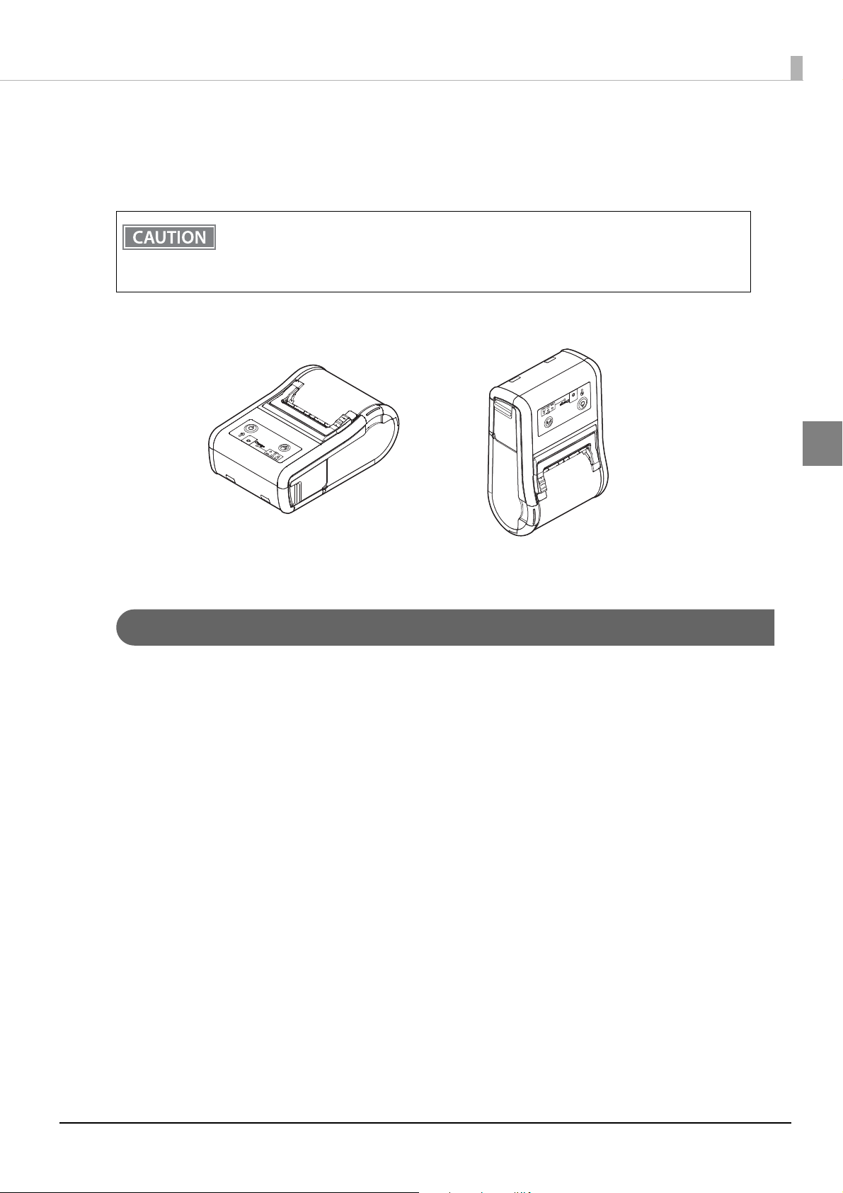
Product Overview
This chapter describes features and specifications of the TM-P60II, a portable thermal printer.
Features
Printing
Maximum printing speed of 100 mm/s is possible.
Printer handling
• The direct connection without Wi-Fi access point brings a simplified configuration procedure of network
settings. (SimpleAP mode)
• Easy drop-in paper loading.
1
• The range of 29.5 mm to 58 mm paper width can be used. A 60 mm paper width can be used by removing the
spacer.
• Belt clip for maximum mobility.
• Long battery life.
• Peeler function is installed as the standard. (It is easy to switch between the label peeler issuing mode and the
label continuous issuing mode.)
Software
• NFC tag built into the printer unit for printing to a touched printer.
• Printing triggered by bar code scan by smart device camera.
• Utility for iOS/Android provides a user-friendly wizard to simplify the connection for smart devices. (Epson
TM Utility for iOS/Android™)
• Command protocol is based on the ESC/POS Proprietary Command System.
• OPOS ADK, JavaPOS ADK, and Windows printer drivers are available.
• Printing various kinds of barcodes, GS1 DataBar, and two-dimensional symbols (PDF417, QR code, Maxi-
Code, Composite Symbology, Aztec Code, DataMatrix) are available.
• Various layouts are possible by using page mode.
• Has a maintenance counter function.
• ePOS-print is possible with the Wi-Fi
® models.
Interfaces
• Has Wi-Fi (IEEE802.11 a/b/g/n) or Bluetooth® interface.
• USB interface is standard equipment.
11

Environment
Has a paper-saving function.
12
Product Configurations
NFC Tag
Interfaces
• Wi-Fi (IEEE802.11a/b/g/n) + USB interface model
• Bluetooth + USB interface model
NFC Tag
Chapter 1 Product Overview
You can perform wireless setup for terminals that support NFC by placing the terminal close to the NFC tag
(mark) on the printer.
*There is no Read/Write function.
Buzzer
Model with the internal buzzer function.
Accessories
1
Included
• Thermal roll paper (for operation check)
• Battery pack (OT-BY60II)
• AC adapter (PS-11)
• AC cable
• Wire saddle
• USB cable
• Setup Guide (Wi-Fi / Bluetooth)
• User’s manual
• Warranty certificate
*1 May not be included, depending on the model.
*1
*1
*1
13

Options
• Battery pack (OT-BY60II)
• AC adapter (PS-11)
• Battery charger (OT-CH60II)
14
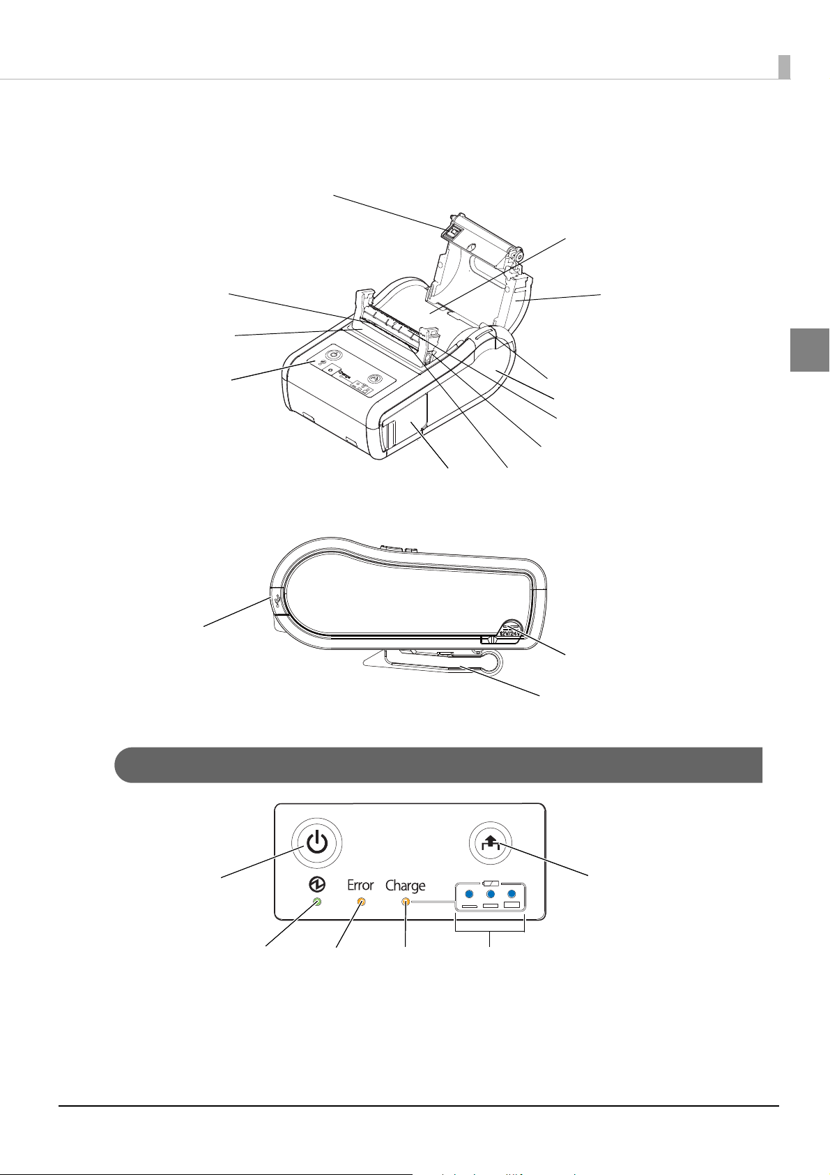
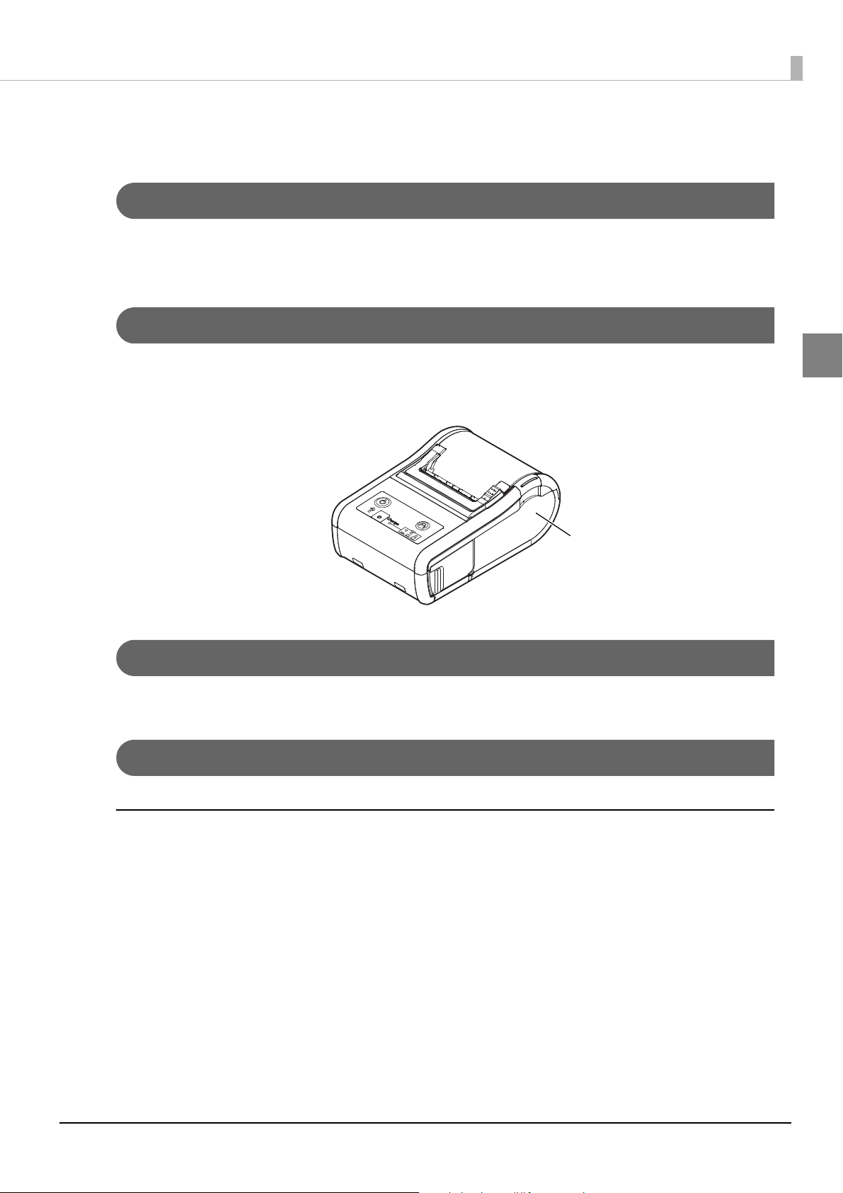
Part Names and Functions
Control panel
Roll paper cover
Open button
Battery cover
Belt clip
USB connector cover
Label peeler sensor
Peeler cover
Connector for AC
Paper sensor
Roll paper holder
Manual cutter
Peeler switch lever
Peeler holder
NFC Tag
Power button
Feed button
Power LED
Error LED
Charge LED
Battery LED
Chapter 1 Product Overview
1
Control Panel
15
Buttons
Power Button
Press this button to turn the printer on. Press this button for 2 seconds or more to turn the printer off.
• After the power button is pressed, it takes the following time before the printer is initialized.
Time to establish the communication is not included.
∗ IEEE802.11a/b/g/n: Approx. 10 sec. after the Power LED comes on.
∗ Bluetooth: Approx. 2 sec. after the Power LED comes on.
• The printer does not operate and the LEDs go out when the battery is not installed in the
printer even if the printer is connected to the AC adapter.
• It is recommended to turn off the printer after executing the power-off sequence command.
The latest values of the maintenance counter are automatically stored in the NV memory (the
values of the maintenance counter are normally stored every 2 minutes.) For detailed information about ESC/POS commands, see the ESC/POS Command Reference.
• If the battery is removed from the printer without executing the power-off sequence command, the values of the maintenance counter are not updated correctly.
• To turn the printer on immediately after turning the printer off, press the Power button after
the LED lights go off.
Feed button
• When receipt paper is selected for the layout setting, pressing this button once feeds paper by one line. Holding this button down feeds paper continuously.
• When paper other than receipt paper is selected for the layout setting, pressing this button feeds paper to the
print starting position on the next label.
• If the printer is used in a situation in which strong light, such as direct sunlight or strong light from illumination strikes the label peeler sensor, even when a label is removed, the label removal status may not be canceled. In this case, pressing this button for approximately 1 second or more cancels the label removal status
and feeds paper to the print starting position on the next label.
Enabling/disabling of the Feed button can be selected by a command. If the command is set to
disable the button, it does not function. For detailed information about ESC/POS commands, see
the ESC/POS Command Reference.
LEDs
The printer does not operate and the LEDs go out when the battery is not installed in the printer
even if the printer is connected to the AC adapter.
Power LED (Green)
• Lights when the power is on.
• Goes out when the power supply is turned off.
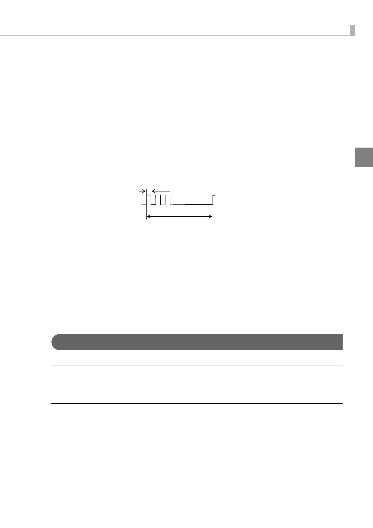
• Flashes when the printer is powering-off or while the Feed button is being pressed in the software setting
mode. With the Wi-Fi models, it flashes also when the printer is being initialized after the power is turned on.
16
Chapter 1 Product Overview
Approx. 5120 ms
Approx. 160 ms
Error LED (Orange)
Lights or flashes when the printer is offline.
• Lights after the power is turned on or after a reset (offline). Automatically goes out when the printer is ready.
• Lights when the remaining battery charge is at E level or zero (no remaining battery charge). (For details
about battery charge levels, see
"Operation Mode When Battery is Low" on page 21.)
• Lights when the printer is offline. (For details about offline, see
• Flashes when an error occurs. (For details about the flash codes, see
• Flashes when the printer is in the following label removal waiting status.
• When the label peeler sensor detects the label after the label is fed to the label removal position.
• When the label peeler sensor detects the label after the power is turned on (initialization) or the peeler
cover is closed.
Flashing pattern
• Goes out during normal operation (online).
"Offline" on page 17.)
"Error Status" on page 23.)
Charge LED (Orange)
• Lights when the battery is being charged.
• Off when the battery is fully charged.
• Flashes when there is abnormality in battery charging.
1
Battery LED (Blue)
The remaining battery charge is indicated by three LEDs only when the battery is installed in the printer. For
details, see
"Operation Mode When Battery is Low" on page 21.
Online and Offline
Online
The printer is online and ready for normal printing unless there is a reason to go offline.
Offline
The printer automatically goes offline under the following conditions:
• During power on until the printer is ready
• When the cover is open
• When paper is out
• When the remaining battery charge is at level E or zero (no remaining battery charge)
• When an error has occurred
17

• The Error LED lights during offline. However, it flashes when an error has occurred.
• For details about the battery charge levels and operation modes, see "Operation Mode When
Battery is Low" on page 21
• The buzzer beeps five times when there is no more paper or an error has occurred. You can disable the buzzer with the memory switches. For details on the memory switch settings, see
"Software Settings" on page 48.
.
18

Chapter 1 Product Overview
Switching Issuing Mode
With the roll paper cover and peeler cover open, you can switch the issuing mode between the label continuous
issuing mode and the label peeler issuing mode by folding the peeler holder under the peeler cover or using the
peeler switch lever.
Label peeler issuing mode: the label is peeled off from the liner when the paper is fed.
The printer operates in the label peeler issuing mode immediately after closing the peeler cover
or turning on the power. When the specified amount of paper is fed, if a label is not detected by
the label peeler sensor, the printer operates in the label continuous issuing mode. When the
cover is opened or the power is turned off, the mode setting is returned to the default (the label
peeler issuing mode).
1
19
Power Functions
You can customize the printer using the power functions, the auto-power off function and battery charge mode
function to save the battery power or minimize the battery deterioration.
Auto-Power Off
The printer turns off the power automatically after the specified amount of time elapses in the power saving status.
The initial setting of the auto-power off function differs depending on the models as follows:
For European models: Enabled (The auto-power off time is set to 60.)
For North America models: Disabled (The auto-power off time is set to 0.)
• The auto-power off time is selectable with the customized value. To set the customized value,
see
"Software Settings" on page 48.
• To disable this function, set the auto-power off time to 0.
• When using a USB, even if the set time is defined, the auto-power off function is disabled.
Battery Charge Modes
The printer acts differently when connected to the AC adapter depending on the battery charge mode.
The printer has two modes and is initially set to the mode 1.
The battery charge mode is selectable with the customized value. To set the customized value,
see
"Software Settings" on page 48.
Mode 1
In the mode 1, the printer charges the battery even if the battery is fully charged.
Mode 2
In the mode 2, the printer charges the battery when the remaining battery charge is less than fully charged.
20
Chapter 1 Product Overview
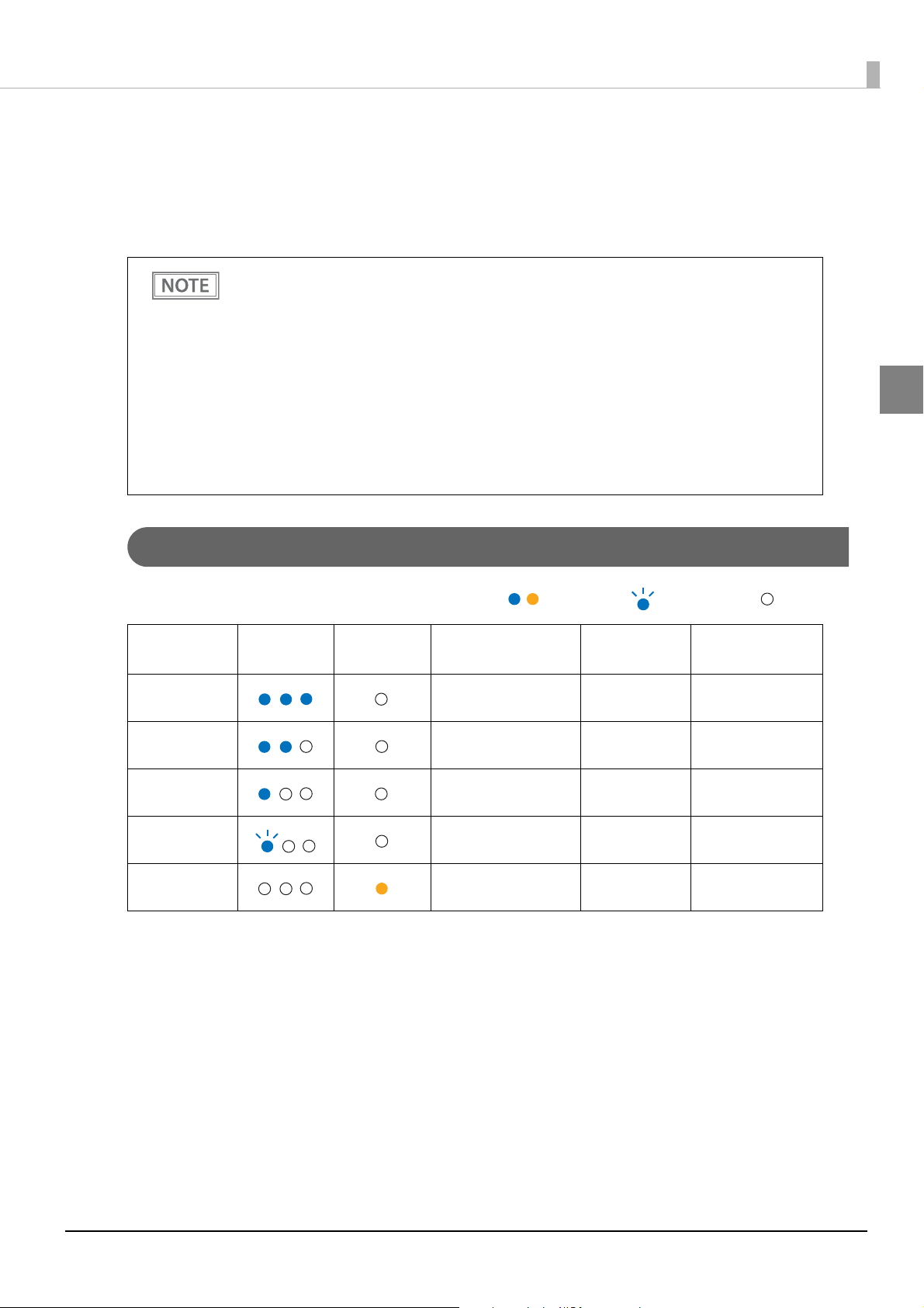
: On
: Flash : Off
Operation Mode When Battery is Low
The printer acts differently depending on the remaining battery charge and the operation mode when battery is
low.
The printer has two modes and is initially set to the mode 1.
• It is recommended to replace or charge the battery when the remaining battery charge goes
down to the level L.
• Replace or charge the battery when the remaining battery charge goes down to the levels S or
E.
• The buzzer beeps five times when the remaining battery charge goes down to the levels L or S.
You can disable the buzzer with the memory switches. To set the memory switches, see
ware Settings" on page 48
• The operation mode when battery is low is selectable with the customized value. To set the
customized value, see
• The remaining battery charge is detected before printing starts and the displayed amount is
then updated. The Battery LED does not indicate the remaining battery charge detected in
real time.
.
"Software Settings" on page 48.
"Soft-
1
Mode 1
Battery LED Error LED
Level H Approx. 60 ~ 100% Possible Possible
Level M Approx. 20 ~ 60% Possible Possible
Level L Approx. 10 ~ 20% Possible Possible
Level S Approx. below 10% Possible* Possible
Level E Approx. 0% Impossible Impossible
*: Printing may stop in the middle.
Remaining
battery charge
Printing Communication
21
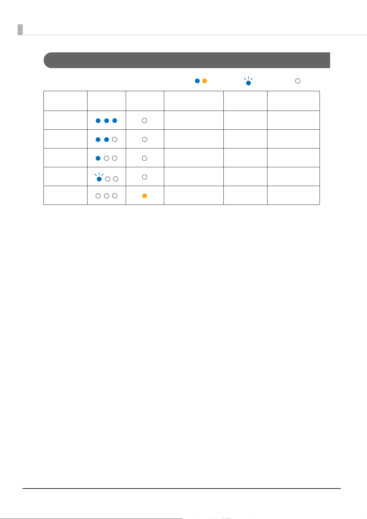
Mode 2
: On
: Flash : Off
Battery LED Error LED
Level H Approx. 60 ~ 100% Possible Possible
Level M Approx. 40 ~ 60% Possible Possible
Level L Approx. 20 ~ 40% Possible Possible
Level S Approx. 10 ~ 20% Possible Possible
Level E Approx. below 10% Impossible Impossible
Remaining
battery charge
Printing Communication
22
Chapter 1 Product Overview
Error Status
When an error occurs, the printer stops operating, goes offline, and the Error LED flashes.
There are three possible error types: automatically recoverable errors, recoverable errors, and unrecoverable
errors.
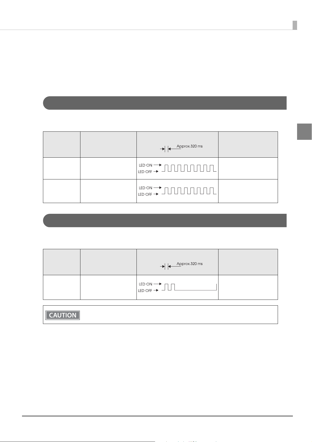
Automatically Recoverable Errors
Printing is no longer possible when automatically recoverable errors occur. They can recover easily, as described
below.
Error LED flash code
Error Error description
Paper error The basic position on the
label cannot be detected.
Tem p e rature
error
The temperature of the
print head, motor driver
IC, or battery is high.
Recovery measure
Recovers automatically
when the cover is opened.
Recovers automatically
when the temperature
goes down.
Recoverable Errors
Printing is no longer possible when recoverable errors occur. They can be recovered easily by sending an error
recovery command after eliminating the cause of the error.
Error LED flash code
Error Error description
Paper layout
error
The paper layout differs
from the actual paper.
Paper jam occurs.
Recovery measure
Recovers by sending an
error recovery command.
1
The error recovery command is valid only if a recoverable error (excluding automatically recoverable errors) occurs.
23
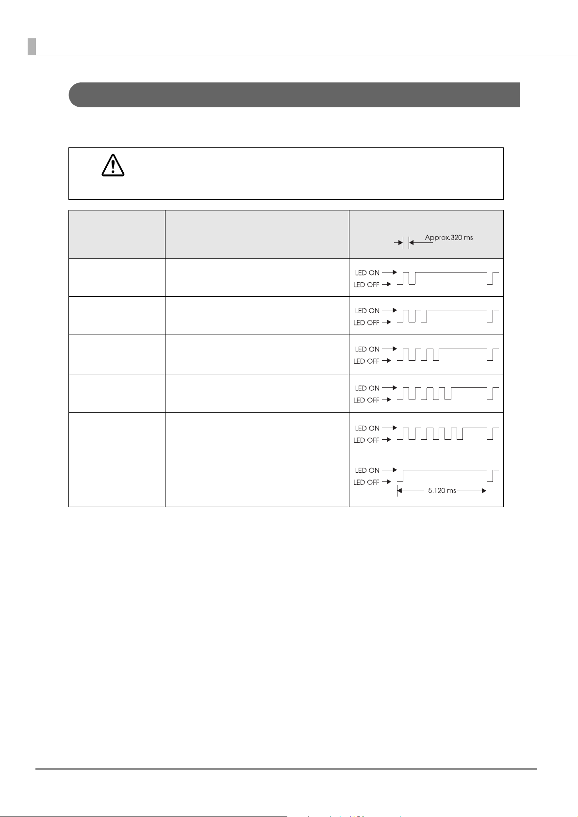
Unrecoverable Errors
Printing is no longer possible when unrecoverable errors occur. If the same error occurs again even after turning the power back on, contact qualified service personnel.
Immediately turn off the power and remove the battery when unrecoverable errors occur.
CAUTION
Error LED flash code
Error Error description
R/W error in memory After R/W checking, the printer does not work
correctly.
High voltage error The power supply voltage is high.
Overload error The temperature of the print head or battery is
extremely high or low.
CPU execution error The CPU is executing an incorrect address.
Wireless communication unit error
Internal circuit error Internal circuits are not connected correctly.
Wireless communication does not work correctly or the wireless communication unit is disconnected.
24
Chapter 1 Product Overview
NV Memory (Non-Volatile Memory)
The printer's NV memory stores data even after the printer power is turned off. NV memory contains the following memory areas for the user:
• NV graphics memory
• User NV memory
• Customized values and memory switches
• User-defined page
• Maintenance counter
As a guide when you program applications, NV memory should be rewritten 10 or fewer times a
day.
NV Graphics Memory
Graphics, such as shop logos to be printed on receipts, can be stored. Even if communication speed is low, high
speed graphic printing is possible.
Use the TM-P60II Utility to register graphics. You can also print and confirm the registered graphics in the TMP60II Utility or NV graphics memory print mode.
1
The NV graphics memory print mode can be executed in the label continuous issuing mode. If it
is executed in the label peeler issuing mode, a paper layout error occurs when paper is detected
by the label peeler sensor.
• For detailed information about the TM-P60II Utility, see the TM-P60II Utility User’s Manual.
• To use the NV graphics memory print mode, see
page 57
.
"NV graphics information print mode" on
User NV Memory
You can store and read text data for multiple purposes, such as for storing a note including customizing or
maintenance information of the printer.
Use ESC/POS commands to store and read the text data.
For detailed information about ESC/POS commands, see the ESC/POS Command Reference.
25
Customized Values and Memory Switches
With the customized values and memory switches, which are software switches for the printer, you can configure various settings of the printer.
To set the customized values and memory switches, see
"Software Settings" on page 48.
User-defined Page
You can store character data in the user-defined page (character code table: page 255) so that you can also print
characters not resident in the printer.
Maintenance Counter
With this function, printer information, such as the number of lines fed and printer operation time after the
printer starts working, is automatically stored in NV memory. You can read or reset the information with TMP60II Utility, the Status API of the APD, or OPOS ADK to use it for periodical checks or part replacement.
Maintenance counter values can also be checked with TM-P60II Utility or by executing a self-test.
Maintenance counter values are usually saved every two minutes except in the power saving status. However, if the printer power is turned off by removing the battery or using up the battery
charge, the latest maintenance counter will not be saved. For detailed information about ESC/
POS commands, see the ESC/POS Command Reference.
26
Chapter 1 Product Overview
Useful Functions for Smart Devices
You can easily connect this product to the network by using the NFC tag built-in to the printer or the QR code
printed on the status sheet.
NFC Tag
Bring a smart device that supports NFC close to the NFC tag to acquire the printer information (information
for specifying the device).
Specify the target printer using the acquired information to connect to the network.
QR Code
Capture the QR code printed on the status sheet with the camera on your smart device to acquire the printer
information (information for specifying the device).
Specify the target printer using the acquired information to connect to the network.
1
• Programming using Epson ePOS SDK is required to use these functions. These functions are
created by combining NFC touch and QR code capturing operations and the target printer
specifications using Printer Easy Select API.
See the "Epson ePOS SDK for Android/iOS User's Manual" and the Epson ePOS SDK sample
program for more details. The sample program also contains a sample implementation method for
reading an NFC tag and capturing a QR code.
• You can try a demo of these functions by using Epson TM Utility for iOS/Android.
27
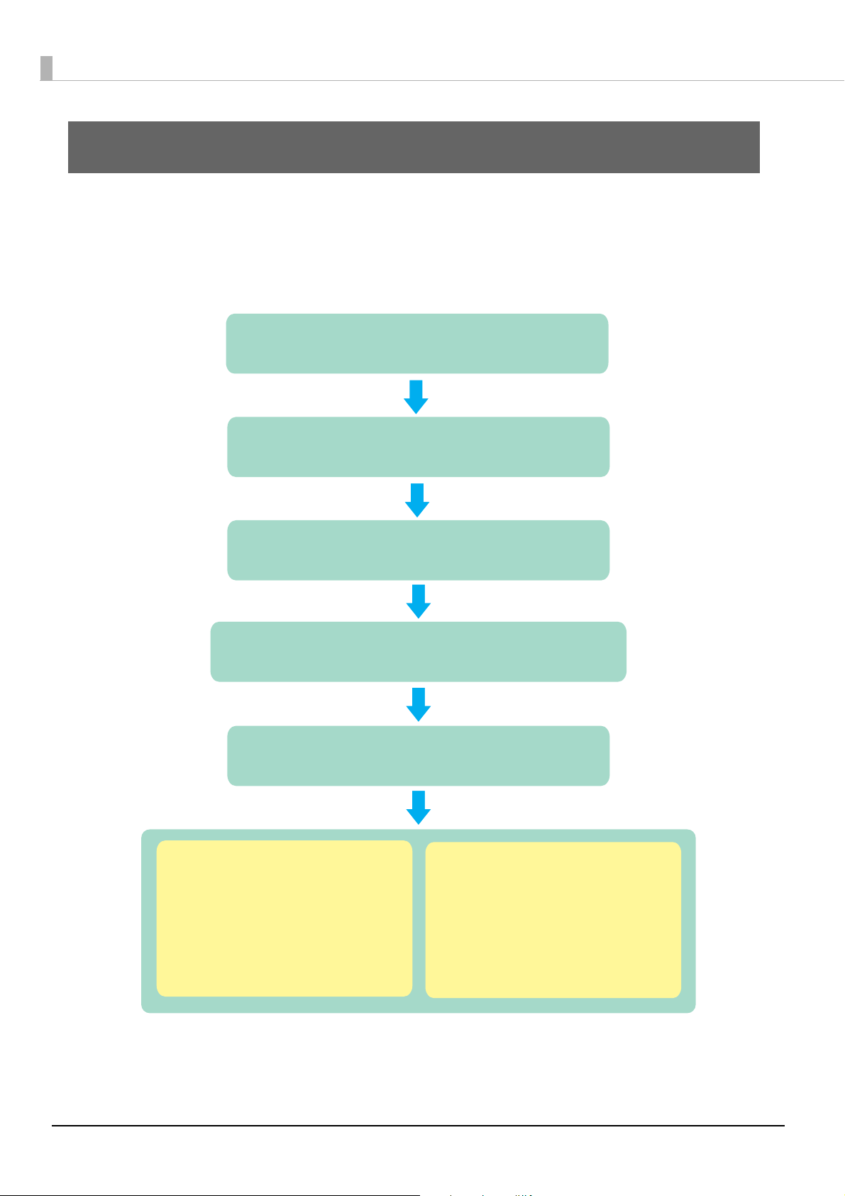
Setup
2. Changing the Paper Width (page 30)
5. Connecting the Printer (page 42)
3. Installing the Battery (page 32)
1. Installing the Printer (page 29)
For Wi-Fi models:
USB Interface (page 42)
or
Wireless LAN Interface (page 43)
For Bluetooth models:
USB Interface (page 42)
or
Bluetooth Interface (page 44)
4. Installing or Replacing the Roll Paper (page 34)
This chapter describes setup and installation of the product and peripherals.
Flow of Setup
This chapter consists of the following sections, along with the setup flow of the product.
28
Chapter 2 Setup
Installing the Printer
You can install the printer horizontally or vertically. You can also carry it using the belt clip on the back of the
printer to hang the printer on your belt.
• When you install the printer vertically, only the orientation shown below is available. Do not
install the printer upside down.
• When you install the printer horizontally, it is recommended to remove the belt clip. Remove
the two screws fixing the clip to remove it.
2
Notes on Using the Wi-Fi Models
• Keep the printer away from the devices, such as kitchen microwaves, that may cause radio wave interference.
• Use channels that are away from the frequency bands that may cause radio wave influence.
• Place shields between the printer and the devices that may cause radio wave interference.
• Select either 2.4 GHz or 5 GHz, whichever is free from radio wave interference.
• In auto channel setting for the access point, do not select a channel in which the printer may cause radio
wave interference.
29
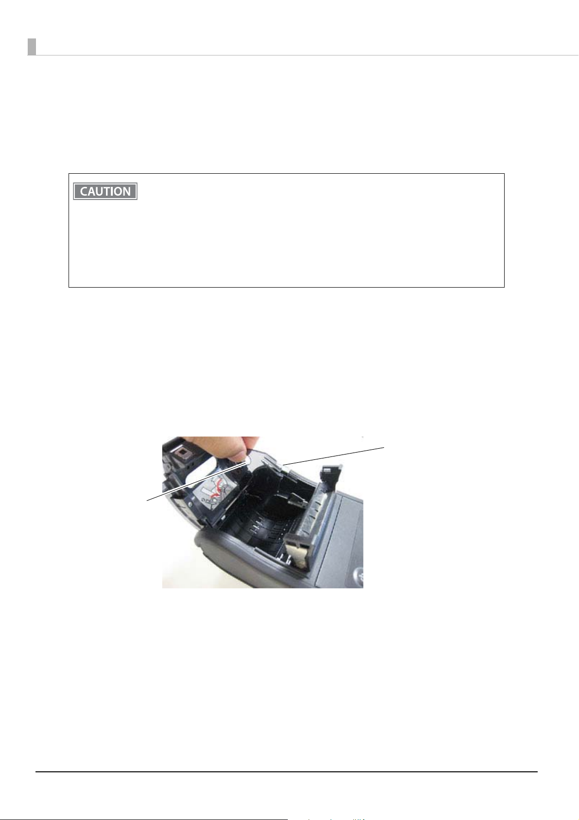
Changing the Paper Width
Top part of the spacer
Hole of the spacer
The printer is initially set to print on 58 mm {2.28"} width paper. When using 29.5 mm {1.16"}, 36 mm {1.82"},
42 mm {1.65"}, 48.5 mm {1.91"}, 55 mm {2.17"}, or 58 mm {2.28"} width paper, adjust the spacer to the position
matching the width of your paper by following the steps below. If you use 60 mm {2.36"} width paper, remove
the spacer installed in the printer.
• When changing the paper width, after adjusting the spacer position, set the paper layout with
ESC/POS commands. If the changed settings are not stored in the NV memory, change the settings with the “Paper layout setting” command. If the changed settings are stored in the NV
memory, change the settings with the “Paper layout setting” command and store the settings
with the “Save the setting values from the work area into the storage area” command. For
detailed information about ESC/POS commands, see the ESC/POS Command Reference.
• Do not increase the paper width after you have used a narrower width because if the printer
has ever been used with narrow paper, part of the head contacts the platen. Therefore, when a
wider setting is used, part of the head may be worn out.
Make sure that the printer is turned off.
1
Press the open button to open the roll paper cover and the peeler cover.
2
Remove the roll paper if there is one in the roll paper holder.
3
Insert your finger into the hole of the spacer and lift it upward to undo the top part
4
that is fixed in one of the slots.
30

Move the spacer to the position matching the width of the paper you are using.
Paper width:
58 mm
55 mm
48.5 mm
42 mm
36 m
29.5 mm
5
Insert the top of the spacer and press it down until it clicks.
6
Chapter 2 Setup
2
31

Installing the Battery
The printer does not operate without a charged battery installed.
Follow the steps below to install the battery.
Be sure to use the battery OT-BY60II.
Using a battery other than the one specified may cause fire, explosion, leakage, overheating or
WARNING
Make sure that the printer is turned off.
1
Open the battery cover.
2
other damage.
• When removing or installing the battery, be sure to turn off the power before doing so.
• Dispose of used batteries according to the instructions.
Install the battery.
3
32

Close the battery cover.
4
To charge the battery, see "Charging Battery" on page 78.
Chapter 2 Setup
2
33

Installing or Replacing the Roll Paper
Follow the steps below to install or replace the roll paper.
When installing or replacing the roll paper, take care not to injure your fingers on the manual cutter.
CAUTION
Use paper that meets the printer specifications. For details about paper specifications, see
Specifications" on page 88
Do not use the roll paper that have the paper glued to the core.
.
When Using the Label Continuous Issuing Mode
Press the open button to open the roll paper cover and the peeler cover.
1
Remove the used roll paper core if there is one.
2
Fold the peeler holder under the peeler cover. This covers the label peeler sensor.
3
"Paper
If you hang the printer vertically on a belt using a belt clip on the back of the printer, see "When installing the
printer vertically" on page 36
.
34

When installing the printer horizontally
Set a new roll of paper in the correct direction inside the roll paper holder, and pull
4
the leading edge of the roll paper.
Chapter 2 Setup
2
Close the roll paper cover.
5
Close the peeler cover.
6
When closing the peeler cover, make sure to close it firmly, pressing both ends.
35

When using the label continuous issuing mode, you can tear off the paper.
When installing the printer vertically
Set a new roll of paper in the correct direction inside the roll paper cover.
4
Be sure that roll paper side is at the bottom when you install the printer vertically.
36
Pull the leading edge of the roll paper, and align the left edge of the roll paper with
5
the edge of the cover.

Close the roll paper cover.
6
Close the peeler cover.
7
When closing the peeler cover, make sure to close it firmly, pressing both ends
Chapter 2 Setup
2
When using the label continuous issuing mode, you can tear off the paper.
37

When Using the Label Peeler Issuing Mode
Peeler holder
Peeler switch lever
Press the open button to open the roll paper cover and the peeler cover.
1
Remove the used roll paper core if there is one.
2
Press the peeler switch lever to lift the peeler holder.
3
If you hang the printer vertically on a belt using a belt clip on the back of the printer, see "When installing the
printer vertically" on page 40
.
When installing the printer horizontally
Set a new roll of paper in the correct direction inside the roll paper holder. Remove
4
the first label off, and pull the label paper so you can set the backing paper in the
peeler holder.
If the first label is not removed when using the label peeler issuing mode, the thickness of the
label and the backing paper overloads the peeler holder, possibly stopping the paper feed motor.
38

Close the roll paper cover.
5
Close the peeler cover.
6
When closing the peeler cover, make sure to close it firmly, pressing both ends.
Chapter 2 Setup
2
39

When installing the printer vertically
Set a new roll of paper in the correct direction inside the roll paper cover. Remove the
4
first label off.
• If the first label is not removed when using the label peeler issuing mode, the thickness of the
label and the backing paper overloads the peeler holder, possibly stopping the paper feed
motor.
• Be sure that roll paper side is at the bottom when you install the printer vertically.
Pull the label paper so you can set the backing paper in the peeler holder, and align
5
the left edge of the roll paper with the edge of the cover.
40

Close the roll paper cover.
6
Close the peeler cover.
7
When closing the peeler cover, make sure to close it firmly, pressing both ends.
Chapter 2 Setup
2
When the label peeler sensor detects the label at power on, the printer goes in the label removal
waiting state and the Error LED flashes. Be sure to remove the label before powering off the
printer. Otherwise, the printer goes into the label removal waiting state when it is powered on
again.
• When the label is completely fed to the peeling position, the printer goes in the label removal
waiting state, so remove the label.
• Removing the issued label enables the label peeler sensor to detect a paper end and the
printer is ready to print the next label.
41

Connecting the Printer
Wire saddle
The TM-P60II has dual interfaces: a built-in USB interface and another interface selected by the customer, wireless LAN or
Bluetooth interface. See the corresponding section for the interface you selected.
• Wi-Fi models: "USB Interface" on page 42 or "Wireless LAN Interface" on page 43
• Bluetooth models: "USB Interface" on page 42 or "Bluetooth Interface" on page 44
• Before connecting the printer, confirm the current interface mode. The printer is initially set to
the Automatic selection mode. To change the interface mode, see
48
.
• Automatic selection:
When the USB cable is connected with a host PC, the USB interface is preferentially selected.
However, if the printer is turned on before turning on a host PC, the wireless LAN/Bluetooth
interface is selected. When the USB cable is not connected with a host PC, the wireless LAN/
Bluetooth interface is selected.
USB Interface
When communicating with a host PC via the USB cable, connect the USB cable to the printer, turn on the PC,
and then turn on the printer. For Windows, you can change the printer settings with the TM-P60II Utility. For
details on the TM-P60II Utility, see "Software Settings" on page 48.
"Software Settings" on page
• Putting the USB cable through the wire saddle prevents the cable from coming unplugged.
• Do not place any weight or stress on the cable when using. Doing so could damage the cable
and connectors.
• When communicating with a host PC via the USB interface, connect the USB cable to the
printer before turning on the printer.
Attach the enclosed wire saddle to the printer as shown in the illustration below.
1
Put the USB cable through the wire saddle.
2
42
Chapter 2 Setup
Connect the USB cable from the host computer to the USB connector.
3
Connect the other end of the interface cable to the host computer.
4
Wireless LAN Interface
Using Epson TM Utility, you can easily connect the printer to the network from an iOS or Android devices. We
also recommend connecting using a USB cable from a Windows computer, and setting up the wireless LAN
using the network setup tool (EpsonNet Config).
• Examine the radio wave situation in the surrounding area before use.
• Avoid using the same channel that is used in the neighboring shops where wireless LAN is
used.
• In the infrastructure mode, W53 and W56 channels are not available to connect to a stealth
SSID access point.
• For detailed information about EpsonNet Config, see the EpsonNet Config manual (operation
guide) or the EpsonNet Config online help.
• If you configure the wireless LAN setting without using EpsonNet Config, use the network
parameters printed on the dynamic status sheet. To print dynamic status sheet, see
Status Sheet Print Mode" on page 66
• To initialize the wireless LAN setting, see
Setting up from a Smart Device
Necessary Items
Prepare the following items.
• Printer: TM-P60II
• Device for setting: iOS or Android device
• Utility for setting: Epson TM Utility for iOS/Android
Running Epson TM Utility for iOS/Android
Run the Epson TM Utility for iOS/Android.
1
2
"Dynamic
.
"Wireless module setup mode" on page 61.
Set from “Wi-Fi® Setup Wizard” in the menu.
2
Setup and Operation Work flow
1. Select the network you want to connect to.
2. Enter the passkey.
3. Perform a test print.
43
Setting up from a Windows Computer
Connect the printer to a PC via the USB cable.
1
See "USB Interface" on page 42.
Turn on the printer.
2
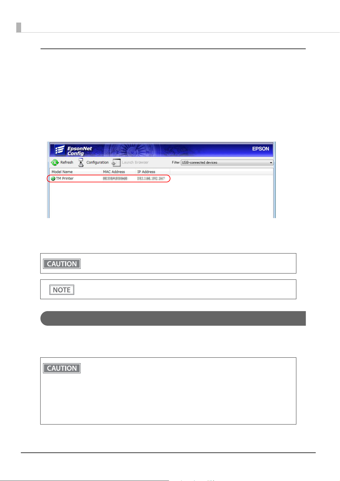
Start up EpsonNet Config.
3
Double-click on the printer.
4
Configure the [Network] settings and the [TCP/IP] settings.
5
Disconnect the USB cable, turn off the printer, and then turn it back on.
6
Be sure to disconnect the USB cable, turn off the printer, and then turn it back on after using
EpsonNet Config via the USB interface.
If you need to configure other settings, use EpsonNet Config (web version). For information about
EpsonNet Config (web version), see
"EpsonNet Config (Web Version)" on page 68.
Bluetooth Interface
Use a tool, such as a built-in Bluetooth connection tool of your device to establish the connection with the
printer. If your device is a Windows computer, use EPSON TM Bluetooth
pair a terminal and the printer.
• If the host computer and the printer are not connected on a continuous basis but rather connected every time the printer starts printing, some time may be needed for the printer to actually start printing after the host computer commands printing. This pause is the time required
for processing the connection between the host computer and the printer, and it depends on
the conditions of the environment where used.
• If data transfer from an application of the host computer has already been completed, data
might remain in the Bluetooth module internal buffer. As such data remaining in the buffer
might be lost when the connection is cut off, use the status or similar functions to check that
transmitted data has been completely printed before cutting off the wireless connection.
® Connector, which is a utility to easily
44
• The device name and passkey are initially set as follows:
∗ Device name: TM-P60II_xxxxxx*
*xxxxxx refers to the last 6 digits of the serial number labeled on the back of your printer.
∗ Passkey: 0000
• For detailed information about EPSON TM Bluetooth
nector User’s Manual.
• The device name and passkey are editable with the TM-P60II Utility.
Setting up from a Smart Device
Necessary Items
Prepare the following items.
• Printer: TM-P60II
• Device for setting: iOS or Android device
• Utility for setting: Epson TM Utility for iOS/Android
Running Epson TM Utility for iOS/Android
Chapter 2 Setup
® Connector, see the TM Bluetooth® Con-
2
Run the Epson TM Utility for iOS/Android.
1
Set from “Bluetooth® Setup Wizard” in the menu.
2
Setup and Operation Work flow
1. Select the printer you want to connect to.
2. Enter the passkey.
3. Perform a test print.
Setting up from a Windows Computer
Follow the procedure below and make the settings.
Have a Bluetooth wireless technology compatible computer ready.
1
Make sure you have installed TM Bluetooth® Connector.
45

Turn on the printer.
2
Start TM Bluetooth® Connector.
3
Select [Search all printers around this computer], and then click [Search].
4
Select the printer to be paired ( Not been paired yet), and then click [Connect].
5
46
If the window to enter a passkey appears, enter a passkey and click [OK].
6
Select the port to be used from the pull-down list, and then click [OK].
7

Printing method Port name
APD print queue ESDPRTxxx (TM-P60II: Queue name)
UPOS ESDPRTxxx (UPOS for TM-P60II)
ESC/POS command Displayed virtual COM port (e.g. COM4)
The “Connection complete” window appears. Click [Test Buzzer] or [Test Printing] to
8
check operation.
Click [Back to Main screen] to return to the main window.
9
Click the “x” button of TM Bluetooth® Connector to exit.
10
Chapter 2 Setup
• If “Error” is displayed when you click the [Search] on the TM Bluetooth
whether:
• The Bluetooth adapter is installed to the computer.
• Bluetooth is ON in the Windows settings.
• If the device is not displayed on the TM Bluetooth
Status shows “ ” after pairing.
Check whether:
• The printer is not turned on.
Turn on the printer. Confirm that the battery is properly loaded in the printer.
• The printer is 10 m or further away from the computer.
• Confirm that there is no other wireless device, such as a microwave oven and cordless tele-
phone, that can interfere with the Bluetooth printer.
• If the printer and the computer are placed in different rooms separated by a wall, move the
printer and/or the computer in the same room.
• The printer may not be detected when the search time is short. Try search again with longer
search time.
• While a computer and printer are communicating, the printer cannot be detected by other
computers. Confirm that the printer to be detected is not communicating with any computer.
® Connector or the TM Bluetooth® Connector
® Connector, check
2
47

Advanced Usage
Software Settings
With the customized values and memory switches, which are software settings for this printer, you can set the
various functions. For an outline of those functions, see the following section.
Use TM-P60II Utility, Software setting mode, or ESC/POS commands, to set the customized values and memory switches.
TM Utility
for iOS, for
Android
User NV memory capacity
NV graphics memory capacity
Print density
Print speed
Interface mode
Command execution during offline
Automatic paper reduction
Automatic power off time
Battery charge mode
Customized values
Offline response
Operation mode when battery is low
Battery status levels
TM-P60II
Utility
Software
setting
mode
ESC/POS
commands
Adjusted value for movement distance of label
peeling position
Allocation of paper position immediately after
the memory switch 8 specific state
Transmission of status notice
Buzzer Settings
Memory
Paper position immediately after the specific
switches
state
USB Class
Bluetooth interface
• For detailed information about TM-P60II Utility, see the TM-P60II Utility User’s Manual.
• For information about how to use the Software setting mode, see
on page 58
• For detailed information about ESC/POS commands, see the ESC/POS Command Reference.
.
"Software settings mode"
48

User NV memory capacity
• 1 KB (initial setting)
• 64 KB
• 128 KB
• 192 KB
NV graphics memory capacity
• None
• 64 KB
• 128 KB
• 192 KB
• 256 KB
• 320 KB
• 384 KB (initial setting)
Chapter 3 Advanced Usage
Print density
Selectable from 70% to 130% (initial setting: 100%)
Depending on the paper type, it is recommended to set the print density as shown in the table below for the best
print quality.
Roll Paper Type Original Paper Type Density Level
Die-cut label DTM9502 130%
Receipt paper P31023, P35024 100%
P30023 110%
• If the print density is set to a darker level, printing speed may be reduced.
• If the print density is set to a darker level, paper dust accumulates on the print head and print
may be faint. For information about how to clean the thermal head, see
Head" on page 79
.
"Cleaning the Thermal
Print speed
Selectable from levels 1 to 10 (Slow ~ Fast) (initial setting: level 10)
• The printing speed changes automatically depending on power supply voltage and the condition of the head temperature.
• Printing speed may be slower, depending on the data transmission speed and the combination of control commands.
3
49

Interface mode
Selectable from: automatic selection, fixed to wireless LAN/Bluetooth interface, or fixed to built-in USB.
• The TM-P60II has dual interfaces: a built-in USB interface and another interface selected by the
customer, wireless LAN or Bluetooth. The tables below describe the modes you can set for the
printer to control the dual interfaces.
• Automatic selection:
When the USB cable is connected with a host PC, the USB interface is preferentially selected.
However, if the printer is turned on before turning on a host PC, the wireless LAN/Bluetooth
interface is selected. When the USB cable is not connected with a host PC, the wireless LAN/
Bluetooth interface is selected.
For Wi-Fi models
Interface mode Wireless LAN Built-in USB
Automatic selection (initial setting)
Fixed to Wireless LAN
Fixed to built-in USB
Available Available
Available Not available
Not available Available
For Bluetooth models
Interface mode Bluetooth Built-in USB
Automatic selection (initial setting)
Fixed to Bluetooth
Fixed to built-in USB
Available Available
Available Not available
Not available Available
50

Chapter 3 Advanced Usage
Command execution during offline
When this function is enabled, you can execute specified commands even if the printer is offline due to specified causes.
• Enabled (initial setting)
• Disabled
Automatic paper reduction
• Extra upper space reduction: disabled (initial setting) or enabled
• Extra lower space reduction: disabled (initial setting) or enabled
• Line space reduction rate: not reduced (initial setting), 25%, 50%, or 75%
• Line feed reduction rate: not reduced (initial setting), 25%, 50%, or 75%
• Barcode height reduction rate: not reduced (initial setting), 25%, 50%, or 75%
• Paper reduction is not performed for space dot lines of graphics printing data.
• When reducing barcode height, be sure to check reading a barcode with your barcode reader
in advance.
Automatic power off time
Selectable from 0 to 60 minutes. The initial setting of the auto-power off function differs depending on the
models as follows:
For European models: Enabled (The auto-power off time is set to 60.)
For North America models: Disabled (The auto-power off time is set to 0.)
When using the USB interface, this functions is disabled even if the time is set.
For detailed information, see
"Auto-Power Off" on page 20.
Adjusted value for movement distance of label peeling position
Selectable from - 32 dots to 32 dots. (initial setting: 0 dots)
3
51

Battery charge mode
• Mode 1 (initial setting)
• Mode 2
For detailed information about the battery charge mode, see "Battery Charge Modes" on page 20.
Offline response
Select “offline response for the TM-P60,” if you replace a TM-P60 with a TM-P60II.
• Offline response for the TM-P60II (initial setting)
• Offline response for the TM-P60
While the offline response for the TM-P60II includes the offline cause, that for the TM-P60 does
not include the offline cause.
Operation mode when battery is low
• Mode 1 (initial setting)
• Mode 2
For detailed information about the operation mode when battery is low, see
When Battery is Low" on page 21
.
"Operation Mode
Allocation of paper position immediately after the memory switch 8 specific state
• Memory switch 8-7 (initial setting)
• Memory switch 8-6 (TM-P60 compatible)
Battery status levels
Select “battery status levels for the TM-P60,” if you replace a TM-P60 with a TM-P60II.
• Battery status levels for the TM-P60II (initial setting)
• Battery status levels for the TM-P60
While the battery status for the TM-P60II has 6 levels, that for the TM-P60 has 4 levels.
52

Transmission of Status notice
• Transmits (initial setting)
• Does not transmit
Buzzer settings
• Buzzer sounds for low battery warning: disabled or enabled (initial setting)
• Buzzer sounds for roll paper end warning: disabled or enabled (initial setting)
• Buzzer sounds for error occurrence warning: disabled or enabled (initial setting)
Paper position immediately after the specific state
• Not specified as “Start of printing” (initial setting)
• Specified as “Start of printing”
To enable this function, select the memory switch 8-7 with the customized value “Allocation of
paper position immediately after the memory switch specific state.”
Chapter 3 Advanced Usage
USB class
• Printer Class
• Vendor Class (initial setting)
Bluetooth interface
• Passkey (initial setting: 0000)
• Device name (initial setting: TM-P60II_xxxxxx)
• Security (initial setting: Low)
• Auto Re-Connect with iOS device (initial setting: Enabled)
• The device name is initially set to TM-P60II_xxxxxx.
(xxxxxx refers to the last 6 digits of the serial number labeled on the back of your printer.)
• When the firmware version is 6.14 ESC/POS or later, you can change the Bluetooth security
settings. (iOS Bluetooth model only)
3
53

Paper Layout Setting
Before printing, it is necessary to set the layout information for paper type and size in the printer. Doing paper
feeding or printing without this layout setting may result in a paper out (no paper left) or an error. In all of the
following cases, therefore, make layout settings before use.
• When using label paper for the first time (except when replacing label paper of the same type)
• When changing the paper type (receipt paper (with/without black mark), die-cut label paper (with/without
black mark))
• When changing the size of the label paper
The paper layout can be set with ESC/POS commands. If the changed settings are not stored in the NV memory, change the settings with the “Paper layout setting” command. If the changed settings are stored in the NV
memory, change the settings with the “Paper layout setting” command and store the settings with the “Save the
setting values from the work area into the storage area” command. For detailed information about ESC/POS
commands, see the ESC/POS Command Reference.
54

Chapter 3 Advanced Usage
Close the roll paper cover, and turn on the printer while pressing the FEED button.
Self-test
Briey press the FEED button. Hold down the FEED button.
Press the FEED button
once briey and then
hold it down.
Open the roll paper cover, and turn on the printer while pressing the FEED
button, and then close the roll paper cover.
Continuing the self-test
Mode selection guidance
NV graphics
information print
Hexadecimal dumping
Press the FEED button
twice briey and then
hold it down.
Software settings
Press the FEED button
three times briey and
then hold it down.
Radio eld intensity
check
Press the FEED button
four times briey and
then hold it down.
Wireless module
setup
Settings/Check Mode
As well as print mode, the following modes are also provided for making various printer settings and checking
items.
• Self-test mode
• NV graphics information print mode
• Software settings mode
• Radio field intensity check mode (Wi-Fi model only)
• Wireless module setup mode
• Hexadecimal dumping mode
• Dynamic status sheet print mode
The self-test mode or hexadecimal dumping mode is selected depending on the operation performed when the
power is turned on.
NV graphic information print mode, Software settings mode, Radio field intensity check mode, and the Wireless module setup mode are selected depending on the FEED button operation performed during a self-test.
3
55
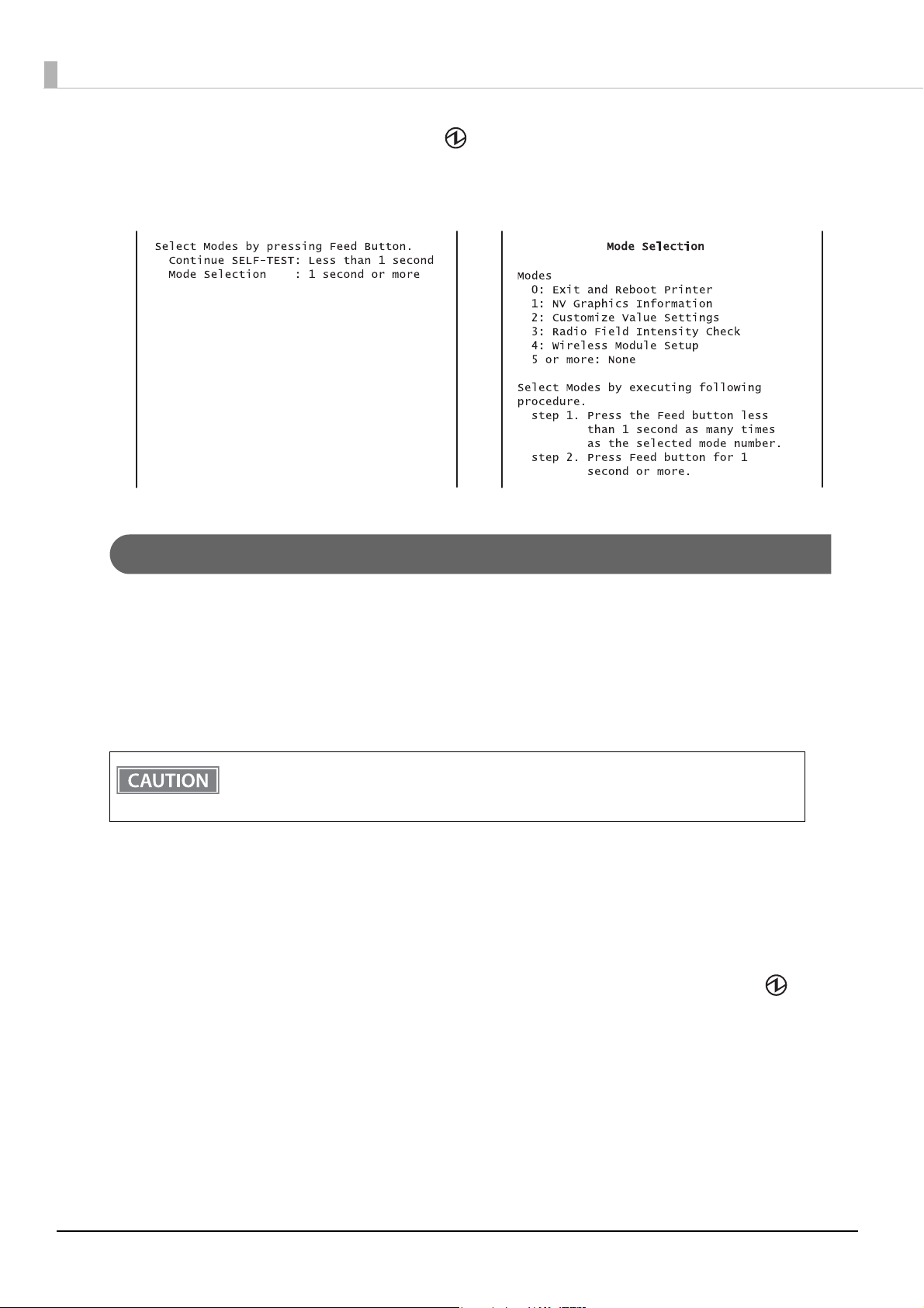
In 1 and 2, the following guidances are printed, the Power LED flashes, and instructs the user's operations.
1. Continuing self-test guidance 2. Mode selection guidance
Self-test mode
You can check the following items using the self-test.
• Firmware version
• Product serial number
• Interface information
• Loaded font
• Maintenance information (head mileage)
The Self-test mode can only be executed in the label continuous issuing mode. If it is executed in
the label peeler issuing mode, a paper layout error occurs when paper is detected by the label
peeler sensor.
Follow the steps below.
Close the roll paper cover.
1
While pressing the FEED button, turn on the printer. (Hold down the FEED button
2
until printing starts.)
After printing the current print status, a Continuing self-test guidance is printed, and the Power
LED flashes.
56
Briefly press the FEED button (less than one second) to continue the self-test.
3
The printer prints a rolling pattern on the roll paper, using the built-in character set.
After “*** completed ***” is printed, the printer initializes and switches to standard mode.
NV graphics information print mode
Prints the following NV graphic information registered to the printers.
• NV graphics capacity
• NV graphics usage capacity
• NV graphics free capacity
• NV graphics registration
• Key code for each data, number of X direction dots, number of Y direction dots
• NV graphics data
The NV graphics information print mode can only be executed in the label continuous issuing mode. If
it is executed in the label peeler issuing mode, a paper layout error occurs when paper is detected by
the label peeler sensor.
Chapter 3 Advanced Usage
For details on NV graphics, see
Follow the steps below.
After running a self test, hold down the FEED button for at least one second, and then
1
select the Mode selection.
The Mode selection guidance is printed, and the Power LED flashes.
After briefly (less than one second) pressing the FEED button once, hold it down for
2
at least one second, to print the NV graphics information.
After information printing, the Mode selection guidance is printed again.
To finish, turn off the power, or select “Exit and Reboot Printer”.
3
"NV Graphics Memory" on page 25.
3
57

Software settings mode
Set the printer's memory switch (customized value).
• Print density
• Automatic paper reduction
• Interface selection
• USB communications settings
• Print speed
• NV memory capacity
The software setting mode can only be executed in the label continuous issuing mode. If it is executed
in the label peeler issuing mode, a paper layout error occurs when paper is detected by the label
peeler sensor.
For details on the memory switch (customized value), see
Follow the steps below.
After running a self test, hold down the FEED button for at least one second, and then
1
• Command execution during offline
• Transmission of status notice
• Buzzer control
• Automatic power off setting
• Paper position immediately after specific state
"Software Settings" on page 48.
select the Mode selection.
The Mode selection guidance is printed, and the Power LED flashes.
Briefly press the FEED button twice (less than one second), hold it down for at least
2
one second, and then select the Software settings mode (Customized value setting).
The Software setting mode guidance is printed, and the Power LED flashes.
58

Chapter 3 Advanced Usage
After briefly pressing the FEED button (less than one second) for the number of times
3
shown in the print result, hold down the button for more than one second, and then
select the setting items.
The setting selected as the setting item, the current settings and initial settings are printed.
Depending on the setting item, you may need to continue selecting the setting item before the settings are printed.
For details on setting items, see "Software Settings" on page 48.
Select a setting by briefly pressing the FEED button (less than one second) for the
4
number of times applicable to the setting, and then hold down the button for more
than one second to confirm your selection.
After saving the settings, the Software setting mode guidance is printed, and the Power LED flashes.
To close Software setting mode, turn off the printer, or select “Exit” to return to Mode
5
selection guidance, and then select “Exit and Reboot Printer”.
• To select 0 as the item number, hold down the FEED button until printing starts.
• If the button is pressed a number of times that is not displayed by the Setup guidance, the opera-
tion is invalid and the same guidance is printed.
3
59
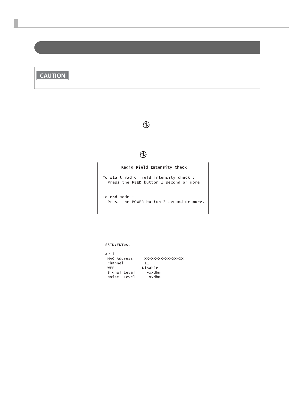
Radio field intensity check mode
Print image for radio field intensity information
Information on the strength of the wireless LAN radio field is printed. (Wi-Fi model only)
The radio field intensity check mode can only be executed in the label continuous issuing mode. If it is
executed in the label peeler issuing mode, a paper layout error occurs when paper is detected by the
label peeler sensor.
Follow the steps below.
After running a self test, hold down the FEED button for at least one second, and then
1
select the Mode selection.
Prints the Mode selection guidance, and the Power LED flashes.
After briefly (less than one second) pressing the FEED button for three times, hold it
2
down for at least one second to select the Radio field intensity check.
The operation guidance is printed, and the Power LED flashes.
Press the FEED button (approximately one second) until the buzzer sounds once.
3
Continue this operation when repeating the Radio field intensity check.
Turn the power off to finish.
4
60
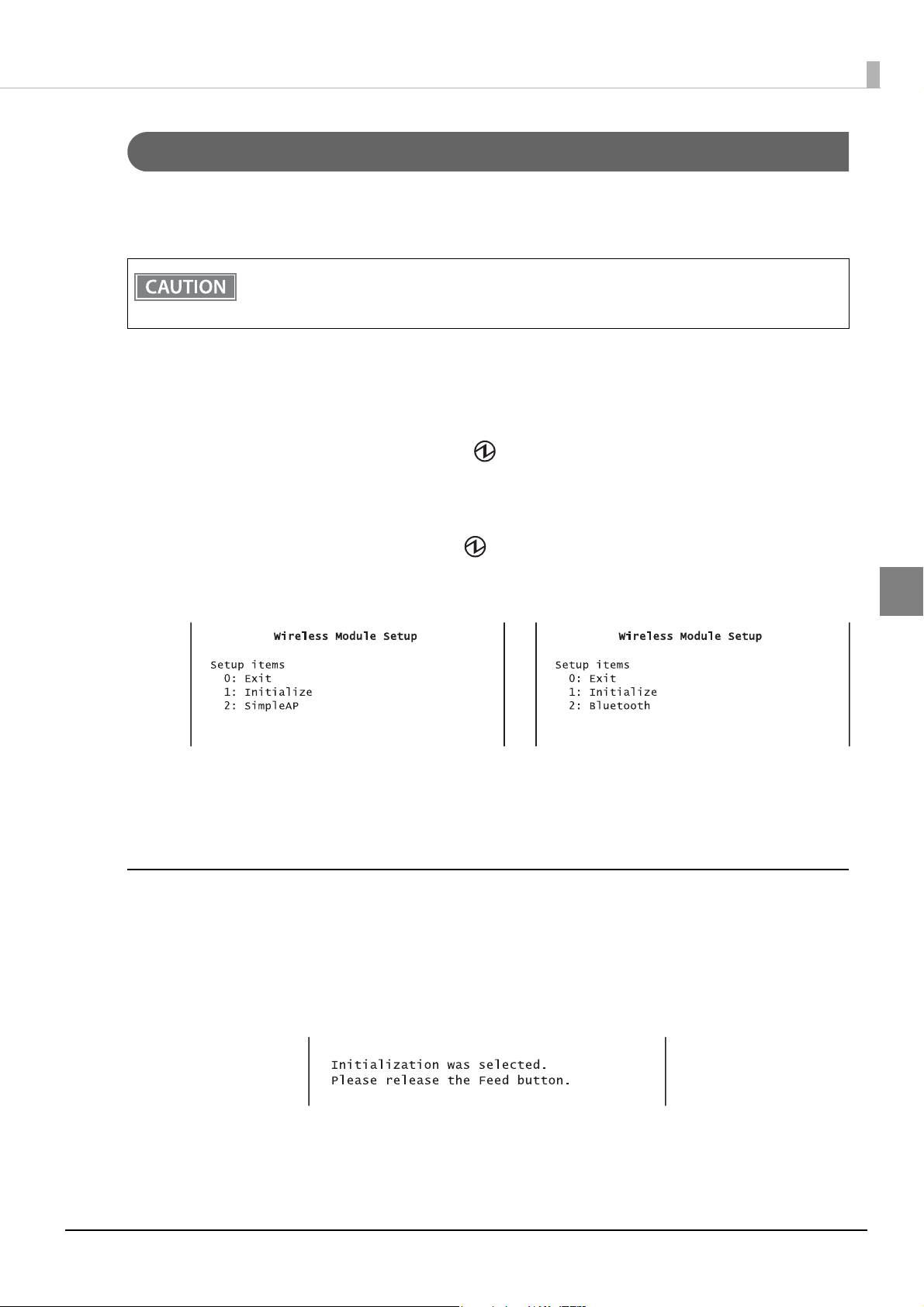
Chapter 3 Advanced Usage
Wireless module setup mode
You can change settings or reset the wireless communication settings. For Wi-Fi models, you can change or
reset the wireless LAN settings, and for Bluetooth models, you can change or reset the Bluetooth settings. For
USB connections, the settings are not reset.
The Wireless module setup mode can only be executed in the label continuous issuing mode. If it is
executed in the label peeler issuing mode, a paper layout error occurs when paper is detected by the
label peeler sensor.
Follow the steps below.
After running a self test, hold down the FEED button for at least one second, and then
1
select the Mode selection.
Prints the Mode selection guidance, and the Power LED flashes.
After briefly (less than one second) pressing the FEED button for four times, hold it
2
down for at least one second to select the Wireless module setup mode.
The operation guidance is printed, and the Power LED flashes.
Wi-Fi model Bluetooth model
Perform one of the following operations according to the printed operation guid-
3
ance.
Initialize
Select 1: Initialize to initialize the wireless communication settings (network parameters). The printer is reset
and restarted.
<Procedure>
After briefly (less than one second) pressing the FEED button once, hold it down until the following message is
printed.
3
61

SimpleAP mode (SimpleAP)
In Wi-Fi model, select 2: SimpleAP to start in SimpleAP mode (the same as the factory default setting).
Select this to use Quick connection for Wi-Fi model.
For information on the Quick connection function, see "Useful Functions for Smart Devices" on page
27
.
Auto re-connect to iOS device (Bluetooth)
In Bluetooth model, select 2: Bluetooth and set in 1: Auto Re-Connect iOS, you can select whether to enable or
disable auto reconnection to iOS devices. (iOS Bluetooth model only)
For information on the Auto re-connect feature, see
on page 104
When the firmware version is 6.12 ESC/POS or later:
After selecting the setting value, press the Feed button again.
1
(Keep pressing the button until the printer starts printing.)
The selected setting value (Enable/Disable) is printed.
The printer starts printing Wireless Module Setup instructions.
2
Changing the settings is complete. You can turn off the printer.
When the firmware version is 6.11 ESC/POS or earlier:
After selecting the setting value, press the Feed button again.
1
(Keep pressing the button until the following message is printed.)
"Please release the Feed button."
The printer restarts.
2
.
"Auto Reconnect Feature (iOS Bluetooth model)"
iAP2 Protocol Settings (Bluetooth)
When the firmware version is 6.14 ESC/POS or later, you can change the accessory protocol (iAP2) settings
used to connect with the device. (iOS Bluetooth model only)
In iOS Bluetooth model, select 2: Bluetooth, and then select 2: iAP2, and you can change the settings.
Setting Explanation
Enable (default) iAP2 is used to connect to the device. This setting should normally be used.
Disable iAP1 is used to connect to the device. Use when there is a problem connecting to the
device using iAP2.
62

Chapter 3 Advanced Usage
Approx. 640 ms
5,120 ms
Bluetooth Security Settings (Bluetooth)
When the firmware version is 6.14 ESC/POS or later, you can change the Bluetooth security settings. (iOS Bluetooth model only)
When the security settings are changed, the link key (pairing information) is removed.
You can also change the settings using the printer Utility and TM Utility for iOS/Android.
In Bluetooth model, select 2: Bluetooth, and then select 3: Security, and you can change the security settings.
Security Pairing Mode Pairing Method
Low Pairing is always possible Just Works
Middle Pairing is possible for one minute after
printing the status sheet
High Pairing is possible for one minute after
printing the status sheet
* When Middle or High is selected, the power LED flashes in the following pattern while pairing is possible.
Pairing method when the security is set to Middle/High (from the printer)
When the security is set to Middle or High and the printer is ready to be paired, perform the following procedure.
Load paper in the printer, and then turn it on.
1
Make sure no errors have occurred and that the printer is not off-line.
Just Works
Numeric Comparison/Passkey Entry
3
2
3
Open the roll paper cover, hold down the FEED button (two seconds), and when the
buzzer sounds, close the roll paper cover.
A status sheet is printed, and the power LED flashes a pattern indicating that pairing
is now possible.
Pairing is possible for one minute after printing the status sheet.
63

Pairing method when the security is set to High (from the host)
When the security is set to High and the printer is ready to be paired, perform the following procedure.
Search for the printer on the Bluetooth settings screen on the host device.
1
Select the printer you want to pair with.
2
The printer prints the Passkey.
Check that the printed Passkey and the Passkey displayed on the host device match,
3
and then select "Pairing" on the host device.
64

Chapter 3 Advanced Usage
Hexadecimal dumping mode
In hexadecimal dumping mode, data from the host computer is printed in hexadecimal numbers and characters. By comparing the print outs and the program, you can check whether or not data is being sent to the
printer correctly.
• The hexadecimal dumping mode can only be executed in the label continuous issuing mode. If
executed in the label peeler issuing mode, a paper layout error occurs when paper is detected by
the label peeler sensor.
• When there are no characters that correspond to the print data, “ . ” is printed.
• If you press the FEED button when there is less than one line of print data, one line is printed.
• During hexadecimal dumping mode, applications that check the printer status may not operate
correctly. The printer only returns the status for the “Real-time transmission status” command.
Follow the steps below.
Open the roll paper cover.
1
While pressing the FEED button, turn on the printer. (Hold down the FEED button
2
until the Error LED turns on.)
Close the roll paper cover.
3
From this point, all data received by the printer is printed in the corresponding hexadecimal numbers and ASCII characters.
Example of printing in hexadecimal dumping mode
To close hexadecimal dumping mode, turn off the printer after printing is complete,
4
or press the FEED button for three times.
3
65

Dynamic Status Sheet Print Mode
Wi-Fi Model
In the dynamic status sheet print mode, the printer prints the dynamic status sheet indicating the wireless LAN
settings.
Do not run this mode while communicating with the wireless LAN interface. Otherwise, printing
might not be performed normally.
• Dynamic status sheet cannot be printed in SimpleAP mode (factory default status).
• Dynamic status sheet cannot be printed when USB cable is connected.
• QR codes can be printed when the firmware version is 6.14 ESC/POS or later.
Follow the steps below.
Make sure the printer is turned on.
1
Open the roll paper cover.
2
Install the roll paper.
3
With the roll paper cover open, keep pressing the Feed button until the buzzer
4
sounds.
Close the roll paper cover.
5
The printer starts printing the dynamic status sheet.
Confirm that “Link Status” value is “Connect” and that “TCP/IP Status” is properly set.
6
After printing, the printer returns to the normal mode.
66

Chapter 3 Advanced Usage
Bluetooth Model
In the dynamic status sheet print mode, the printer prints the dynamic status sheet indicating the Bluetooth settings.
Dynamic status sheet can be printed when the firmware version is 6.14 ESC/POS or later.
Make sure the printer is turned on.
1
Open the roll paper cover.
2
Install the roll paper.
3
With the roll paper cover open, keep pressing the Feed button until the buzzer
4
sounds.
Close the roll paper cover.
5
The printer starts printing the status sheet.
After printing, the printer returns to the normal mode.
3
67

EpsonNet Config (Web Version)
EpsonNet Config (Web version) is a utility to configure the network and other settings on a web browser.
Starting EpsonNet Config (Web Version)
Follow the steps below to start up EpsonNet Config (web version).
Start up a PC connected to the network.
1
Start up the web browser and input the printer’s IP address (http://printer’s IP
2
address) in the address bar as shown below.
http://xxx.xxx.xxx.xxx
• You can check the printer's IP address using the dynamic status sheet or in self-test mode. For
details on printing the dynamic status sheet, see
66
. For details on the self-test mode, see "Software Settings" on page 48.
• A user name and a password will be required on the authentication screen. The settings for
the user name and password are as follows. The default setting for the password varies
depending on the Wi-Fi model's firmware version.
"Dynamic Status Sheet Print Mode" on page
Wi-Fi model's
rmware version
Before 1.30
1.30 or later
You can check the Wi-Fi model's firmware version using the self-test. (
56)
You can check the product's serial number using a self-test or on the manufacturing
nameplate attached to the product. (
You can change the password with [Password] in the Optional configuration menu.
• In the initial setting, a warning message for authentication may appear when you access
EpsonNet Config (web version) from a browser.
"epson"
"epson"
PasswordUser name
"epson"
Product serial number (10 alphanumeric characters,
case sensitive)
"Self-test mode" on page
"Self-test mode" on page 56)
68

EpsonNet Config starts.
Chapter 3 Advanced Usage
3
69
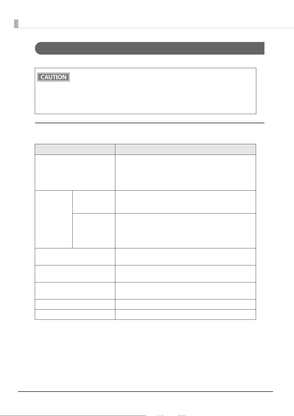
Settings
Select from the menu list on the left to check or configure the settings.
Enable the time server when using a certificate. Otherwise, the printer's Stored Date/Time may
not be set correctly and the wireless LAN may be unavailable. If this happens, enable the time
server, or initialize the Stored Date/Time from one of the following:
• EpsonNet Config
• EpsonNet Config (Web Version)
• Wireless module setup mode
You can check the printer's Stored Date/Time from the dynamic status sheet.
Information menu
You can check the settings as shown in the table below.
Menu Settings
Administrator Name, Location, interface Card Model Name, MAC Address,
Hardware Version, Software Version, Model Name,
Basic Information
Communication Standard, Network Mode, SSID, Channel, Transmission
Rate, Access Point MAC Address, Signal Condition,
Printer Status
IP Address Settings (Acquiring the IP Address, IP Address, Subnet Mask,
IPv4 Address
TCP/IP
DNS/DDNS
SNMP
Bonjour
Time Setting
Timeout Print (LPR, RAW (Port9100))
ePOS-Print Version, ePOS-Print (Disable/Enable), Device ID
Default Gateway)
Set Using Automatic Private IP Addressing (APIPA)
DNS Server Addresses (IPv4) Settings (Acquire DNS Server Address Automatically, DNS Server Addresses)
Domain Name Setting (Acquire Domain Name Automatically, Fully Qualified Domain Name, Register the Network Interface’s Address to DNS
Server)
Community (Read Only, Wellknown Community Name)
IP Trap (Trap1/2, Address, Community)
Bonjour (Disable/Enable)
Bonjour Name, Bonjour Printer Name, Location
Use Time Server
Time Server Address, Update Interval, Time Server Status
70

Configuration menu
You can configure the settings as shown in the table below.
Menu Settings
Wireless Settings (Communication Standard, Network Mode, SSID, Channel, Encryption Type)
WPA Pre-Shared Key, Default WEP Key, WEP Key 1/2/3/4, Authentication
Wireless
Algorithm
Power Save
Roaming
AP Density
Chapter 3 Advanced Usage
Security
Authentication
TCP/IP
SNMP
Bonjour
SSL/TLS
Certificate List
Certificate Import
IPv4 Address
DNS/DDNS
Server Certificate, Encryption Strength, Automatic Redirect HTTP to
HTTPS
Self-Signed Certificate (Status, Subject)
CA-Signed Certificate 1~3 (Status, Subject)
CA Certificate 1~10 (Status, Subject)
Certificate Import (File Type, File Name, Password)
IP Address Settings (Acquiring the IP Address, IP Address, Subnet Mask,
Default Gateway)
Set Using Automatic Private IP Addressing (APIPA)
DNS Server Addresses (IPv4) Settings (Acquire DNS Server Address Automatically, DNS Server Addresses)
Host Name and Domain Name Setting (Acquire Host Name and Domain
Name Automatically, Host Name, Domain Name, Register the Network
Interface’s Address to DNS Server)
Community (Read/Write, Wellknown Community Name)
IP Trap (Trap1/2, Address, Community)
Bonjour (Disable/Enable)
Bonjour Name, Bonjour Printer Name, Location
3
Time Setting
Timeout Print (LPR, RAW (Port9100))
ePOS-Print Version, ePOS-Print (Disable/Enable), Device ID
Use Time Server
Time Server Address, Update Interval
71

• [Roaming] and [AP Density] in the [Wireless] menu can be set only when the Wi-Fi model's
firmware is version 1.17 or later.
• [Wellknown Community Name] in the [SNMP] menu can be set only when the Wi-Fi model's
firmware is version 1.19 or later.
The initial value is enabled.
If you disable this setting, there are the following restrictions.
∗ TM drivers
The battery status cannot be acquired.
Port opening is extended by approximately 2 seconds.
∗ Deployment Tool
The model name cannot be acquired.
∗ EpsonNet Config/Monitoring Tool
The model name, status, and setting information cannot be acquired.
The setting cannot be changed.
• You can also select the following functions from the optional configuration menu.
∗ Administrator Information: Use to register administrator name and the printer location.
∗ Reset: Use to reset the interface card or restore the default settings.
∗ Password: Use to change the password.
The default setting for the password varies depending on the Wi-Fi model's firmware
version.
Wi-Fi model's
rmware version
Before 1.30
1.30 or later
You can check the Wi-Fi model's firmware version using the self-test. ("Self-test mode" on
page 56)
You can check the product's serial number using a self-test or on the manufacturing
nameplate attached to the product. (
Password
"epson"
Product serial number (10 alphanumeric characters, case sensitive)
"Self-test mode" on page 56)
72

Chapter 4 Application Development Information
Application Development Information
This chapter describes how to control the printer and gives information useful for printer application development.
Controlling the Printer
The printer supports the following command systems:
• ePOS-Print XML (Wi-Fi model only)
• ESC/POS
Users can control the printer by using the aforementioned commands, or the following development kits or
drivers.
• ePOS-Print SDK
• OPOS ADK
• OPOS ADK for .NET
• JavaPOS ADK
• EPSON Advanced Printer Driver (APD)
ePOS-Print XML
ePOS-Print XML is the Epson original control command system for POS printers defined in XML. With ePOSPrint XML commands, you can print in environments where http communication is available and from OS
applications.
For detailed information about ePOS-Print XML, see the ePOS-Print XML User's Manual.
On this printer, ePOS-Print XML is only supported by a Wi-Fi model.
To use ePOS-Print XML or SDK for JavaScript, set ePOS-Print to Enable in EpsonNet Config (Web Version) beforehand.
For details about EpsonNet Config (Web Version), see
"EpsonNet Config (Web Version)" on page 68.
ESC/POS
ESC/POS is the Epson original printer command system for POS printers and customer display. With ESC/POS
commands, you can directly control all the TM-P60II printer functions, but detailed knowledge of printer specifications or combination of commands is required, compared to using drivers and applications.
For detailed information about ESC/POS commands, see the ESC/POS Command Reference.
4
73
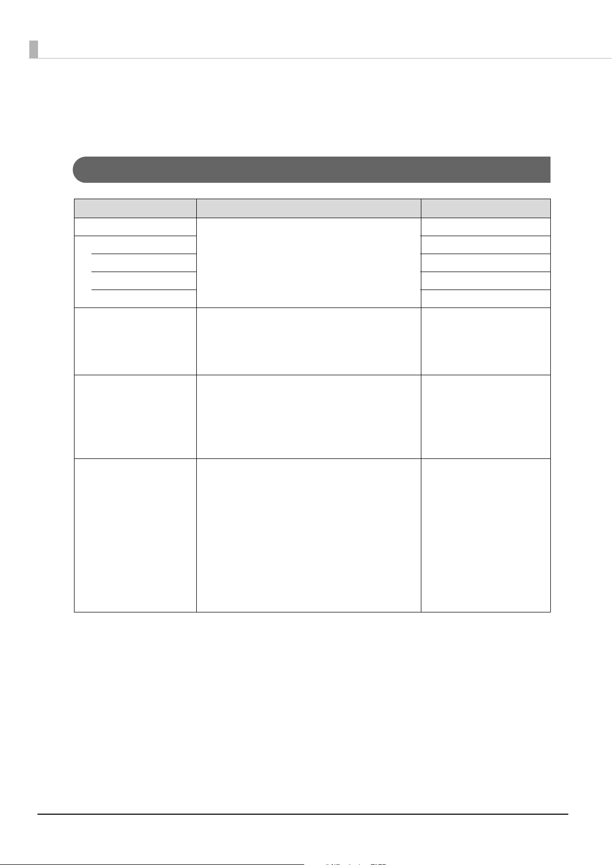
Software and Manuals
The following software and manuals are provided for application development.
Development Kits
Software Description Targ e t model
ePOS-Print SDK This development kit is for controlling the printer from
for iOS Bluetooth model, Wi-Fi model
for Android Bluetooth model, Wi-Fi model
for Windows Store Apps Bluetooth model, Wi-Fi model
for JavaScript Wi-Fi model only
Web applications and native applications of smart
devices. It includes libraries, manuals, and sample programs.
EPSON OPOS ADK This OCX driver can control POS peripherals using OLE
technology.*1
Because controlling POS peripherals with original commands is not required on the application side, efficient
system development is possible.
EPSON OPOS ADK for .NET The OPOS ADK for .NET is a POS industry standard
printer driver compatible with Microsoft POS for .NET.
It allows you to develop applications that are compatible
with the UPOS (Unified POS) specification.
When developing applications, use a separate development environment such as Microsoft Visual Studio .NET.
EPSON JavaPOS ADK JavaPOS is the standard specification which defines an
architecture and device interface (API) to access various
POS devices from a Java based system. Using JavaPOS
standard API allows control with Javabased applications
of functions inherent to each device. A flexible design
with Java language and JavaPOS enables many different
types of computer systems, such as stand alone or network configuration, to use a same application. You can
use JavaPOS to build applications and drivers independently of platforms. This allows flexible configurations using thin clients to meet the system
requirements.
Bluetooth model, Wi-Fi model
Bluetooth model, Wi-Fi model
Bluetooth model, Wi-Fi model
∗1: OLE technology developed by Microsoft divides software into part blocks. The OPOS driver is presupposed to be
used with a development environment, such as Visual Basic, unlike ordinary Windows printer drivers. It is not a
driver to be used for printing from commercial applications.
You can acquire documents regarding the UnifiedPOS from the following link.
https://www.omg.org/retail/unified-pos.htm
74

Drivers
Chapter 4 Application Development Information
Software Description
EPSON Advanced Printer
Driver (APD)
EPSON TM Virtual Port Driver This is a serial/parallel-USB/LAN conversion driver to make an Epson
In addition to ordinary Windows printer driver functions, this driver
has controls specific to POS. The Status API (Epson original DLL) that
monitors printer status and sends ESC/POS commands is also
attached to this driver.
TM/BA/EU printer connected via USB or LAN accessible from a POS
application through a virtual serial or parallel port. It allows you to
directly control devices connected via USB or LAN with ESC/POS commands without making changes in the POS application that controls
devices connected via a serial or parallel interface.
Utilities
Software Description
TM-P60II Utility A utility for checking and changing various printer settings. Use this utility to:
• Check the current settings
• Test ope rat ion
• Store logos
• Set paper saving
• Set printing control
• Set communication interfaces
• Save/restore settings
Operating
environment
Windows
Windows
Operating
environment
Windows
4
Epson TM Utility A utility that is available on the App Store or Google Play. Use this to perform
wireless connection setup and change settings on the printer from iOS and
Android devices. This utility also comes with the following sample printing
functions:
• Sample receipt printing
• Customized receipt printing
• Printer status display
• Quick pairing by NFC/QR code
• Easy print by NFC/QR code
EpsonNet Config A network setting tool for Epson network products.
In the case of this printer, you can use this tool to check and/or set network
parameters by connecting the Wi-Fi model to a computer for setup via the USB
interface.
iOS, Android
Windows, Mac
75
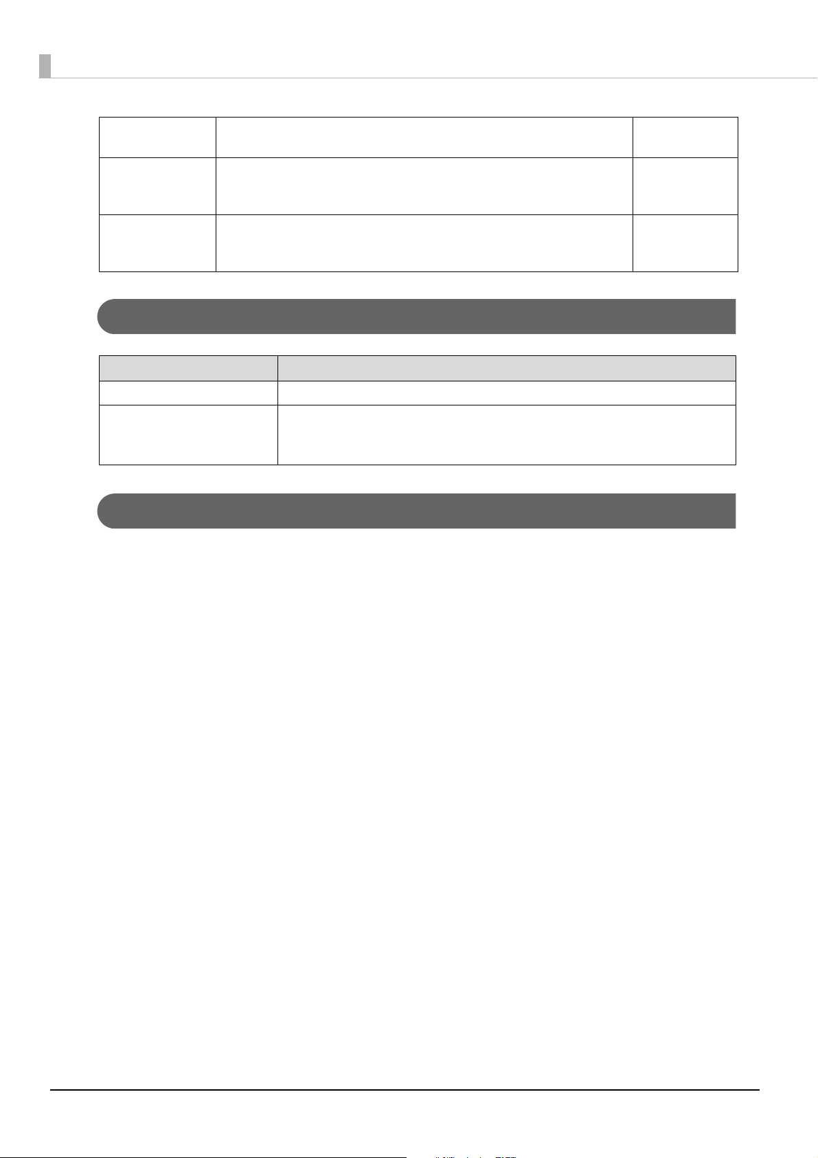
TM Bluetooth®
Connector
Use to pair a Bluetooth printer and associate the generated Bluetooth port with
that used by the driver and applications.
Windows
Deployment Tool Use to make network and printer settings simultaneously, via USB. Allows you
to make settings efficiently at the time of introducing TM printers for the first
time, or when configuring multiple TM printers at the same time.
Monitoring Tool Use to check a list of status for the Epson printers connected to the network.
You can also update certificates for multiple printers used for WPA-Enterprise in
a batch.
Windows
Windows
Others
Manual Description
ePOS-Print XML User's Manual Describes ePOS-Print XML statements. This manual comes with sample programs.
ESC/POS Command Reference Web contents including detailed description of ESC/POS commands, character code
tables, and sample programs. This manual is accessible from the following URL:
www.epson-biz.com/pos/reference/
Download
You can obtain software and manuals from one of the following URLs.
For customers in North America, go to the following web site:
www.epson.com/support/
For customers in other countries and regions, go to the following web site:
www.epson-biz.com/
76

Chapter 4 Application Development Information
iOS Application Development and Distribution
If registering an application that uses Bluetooth in the App Store, Epson must submit an application to Apple in
advance. Please apply for each application you want to register in the App Store from the URL below.
www.epson-biz.com/ais/E/
4
77

Handling
This chapter describes basic handling of the printer.
Charging Battery
Follow the steps below to charge the battery. You can charge the battery using the printer itself with the AC
adapter (PS-11) or using the optional multi-charger (OT-CH60II).
Be sure to use the battery OT-BY60II.
Using a battery other than the one specified may cause fire, explosion, leakage, overheating or
WARNING
other damage.
• The battery can be charged only when the temperature is 0 ~ 40°C {32 ~ 104°F}.
• Dispose of used batteries according to the instructions.
• Do not remove the battery during charging.
• Fully charging a battery that is fully discharged while the printer is turned off will take approx-
imately 2.5 hours.
• Charging the battery at 35°C {95°F} or higher may require a longer charging time than the
specified one.
• You can use the printer during the battery charging; however, do not disconnect the AC
adapter during printing.
• For information on the AC adapter (PS-11), see its User’s Manual.
• For information on the optional multi-charger (OT-CH60II), see its User’s Manual.
Install the battery.
1
See "Installing the Battery" on page 32.
Connect the AC adapter to the connector for the AC adapter.
2
Charging starts. The Charge LED flashes while charging the battery.
78

Chapter 5 Handling
Cleaning the Printer
Cleaning the Printer Case
Be sure to unplug the AC cable from the wall socket, remove the battery, and turn off the printer before cleaning. Wipe the dirt off the printer case with a dry cloth or a damp cloth.
Never clean the product with alcohol, benzine, thinner, or other such solvents. Doing so may
damage or break the parts made of plastic and rubber.
Cleaning the Thermal Head
Epson recommends cleaning the thermal head periodically (generally every 3 months) to maintain receipt print
quality.
•
After printing, the thermal head can be very hot. Do not touch it and let it cool before you
clean it.
•
CAUTION
Turn off the printer, open the roll paper cover and the peeler cover, and clean the thermal elements of the thermal head
with a cotton swab moistened with an alcohol solvent (ethanol or IPA).
Do not damage the thermal head by touching it with your fingers or any hard object.
5
79
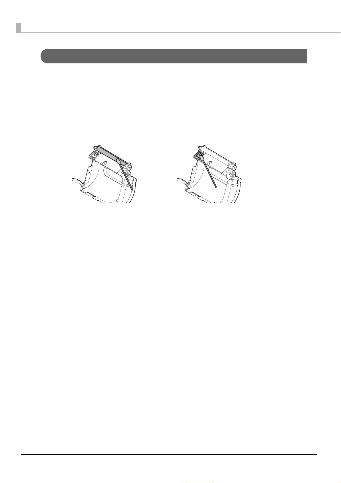
Cleaning the Platen Roller/Paper Sensor
When paper dust accumulates on the platen roller or the paper sensor, follow the steps below to clean them. To maintain
good functional capabilities, clean them regularly
Turn off the printer, and open the roll paper cover and the peeler cover.
1
Clean the platen roller and the paper sensor with a cotton swab lightly moistened
2
with water.
Close the covers after the water has dried.
3
(generally every 3 months).
80

Chapter 5 Handling
Label
Cleaning the Peeler Unit
After the peeler is used for a prolonged period of time, the glue from the labels accumulates on the roller or the
peeler holder of the peeler unit. If you leave the roller or the peeler holder in such a condition, the glue may stick
to issued labels, or a paper jam may occur. To prevent malfunctions and maintain good print quality, clean them
regularly (generally every 20,000 labels).
Do not use any alcohol based solvents for cleaning. Such solvents may enter the roller shaft and
cause a malfunction of the peeler.
Turn off the printer, and open the roll paper cover and the peeler cover.
1
Remove the glue with a wasted label.
2
Close the covers.
3
5
81

Replacement of the TM-P60
The TM-P60II is designed so that it can smoothly replace the TM-P60. This chapter describes useful information for the replacement.
Compatibility
TM-P60 TM-P60II
Paper width Changeable (29.5 mm {1.16"}, 36 mm {1.82"}, 42 mm {1.65"}, 48.5 mm
{1.91"}, 55 mm {2.17"}, 58 mm {2.28"}, 60 mm {2.36"})
Density 203 × 203 dpi
Paper type Receipt (with/without black mark)
Die-cut label paper (with/without black mark)
Internal buffer for NV area 384 KB
External Dimensions 65 × 103 × 159 mm
Case color EDG (Epson Dark Grey) EBCK (Epson Black)
Belt clip Attached
Shoulder strap Optional Not available
Reliability Printer mechanism 10 million lines printing
Thermal head 100 million pulses (for each element)
MTBF 120,000 hours
MCBF 16 million lines
Power supply From the battery or AC adapter Only from the battery
Environmental
Conditions
For operation Without AC adapter and with bat-
tery:
0 to 50°C, 10 to 90% RH
With AC adapter and without battery:
0 to 45°C, 10 to 90% RH
With AC adapter and battery:
0 to 40°C, 10 to 90% RH
For print quality 5 to 45°C, 10 to 90% RH Without AC adapter and with bat-
Without AC adapter and with battery:
0 to 45°C, 10 to 90% RH
With AC adapter and battery:
0 to 40°C, 10 to 90% RH
tery:
5 to 45°C, 10 to 90% RH
With AC adapter and battery:
5 to 40°C, 10 to 90% RH
82

Chapter 6 Replacement of the TM-P60
TM-P60 TM-P60II
Roll paper Width 29.5 mm, 36 mm, 42 mm, 48.5 mm, 55 mm, 58 mm, 60 mm
Original paper type TF50KS-E, P300, P310, P350, ETLA
series
Roll diameter Up to 51 mm
LEDs Error LED Red LED Orange LED
Battery LED Red LED 3 Blue LEDs
Dip switches Dip switches 1-2, 1-3, 1-4 assigned
for serial interface settings
Memory switches Memory switches 8-1~ 8-8 Same as the TM-P60 except Mem-
Offline response
(See
"Software Settings" on page 48.)
Battery status levels
(See
"Software Settings" on page 48.)
Interface Serial RS-232 Not available
USB Not available USB 2.0
Bluetooth
(Factory option)
Offline response excluding offline
cause
4 levels 6 levels
Ver. 1.1 Ver. 2.1 + EDR/
TF50KS-E, P30023, P31023, P35024,
V9NS5, DTM9502
Dip switches are not available.
ory switches 8-3, 8-6, and 8-7.
Offline response including offline
cause
Ver. 3.0 (EDR supported)
Wi-Fi
(Factory option)
Wi-Fi default mode Ad-hoc Infrastructure
Wi-Fi security WEP WEP, WPA, WPA2-Personal/Enter-
ePOS-Print Not available Available with the Wi-Fi models
Startup time Approx. 2 sec. Wi-Fi models: Approx. 10 sec.
ESC/POS commands You can control a TM-P60II with the ESC/POS commands that you used for
Drivers APD Available Available
OPOS ADK Available Available
OPOS ADK for .NET Available Available
JavaPOS ADK
(Windows)
JavaPOS ADK
(Linux)
802.11b (2.4 GHz) 802.11b/g/n (2.4GHz)
802.11a/n (5GHz)
prise
Bluetooth models: Approx. 2 sec.
a TM-P60.
Available Available
Available Not available
6
Power supply unit PS-10 PS-11
83

TM-P60 TM-P60II
Battery LIP-2500 OT-BY60II
Time for battery charging by printer Approx. 4 hours Approx. 2.5 hours
dpi: dots per inch
cpl: Characters per line
84
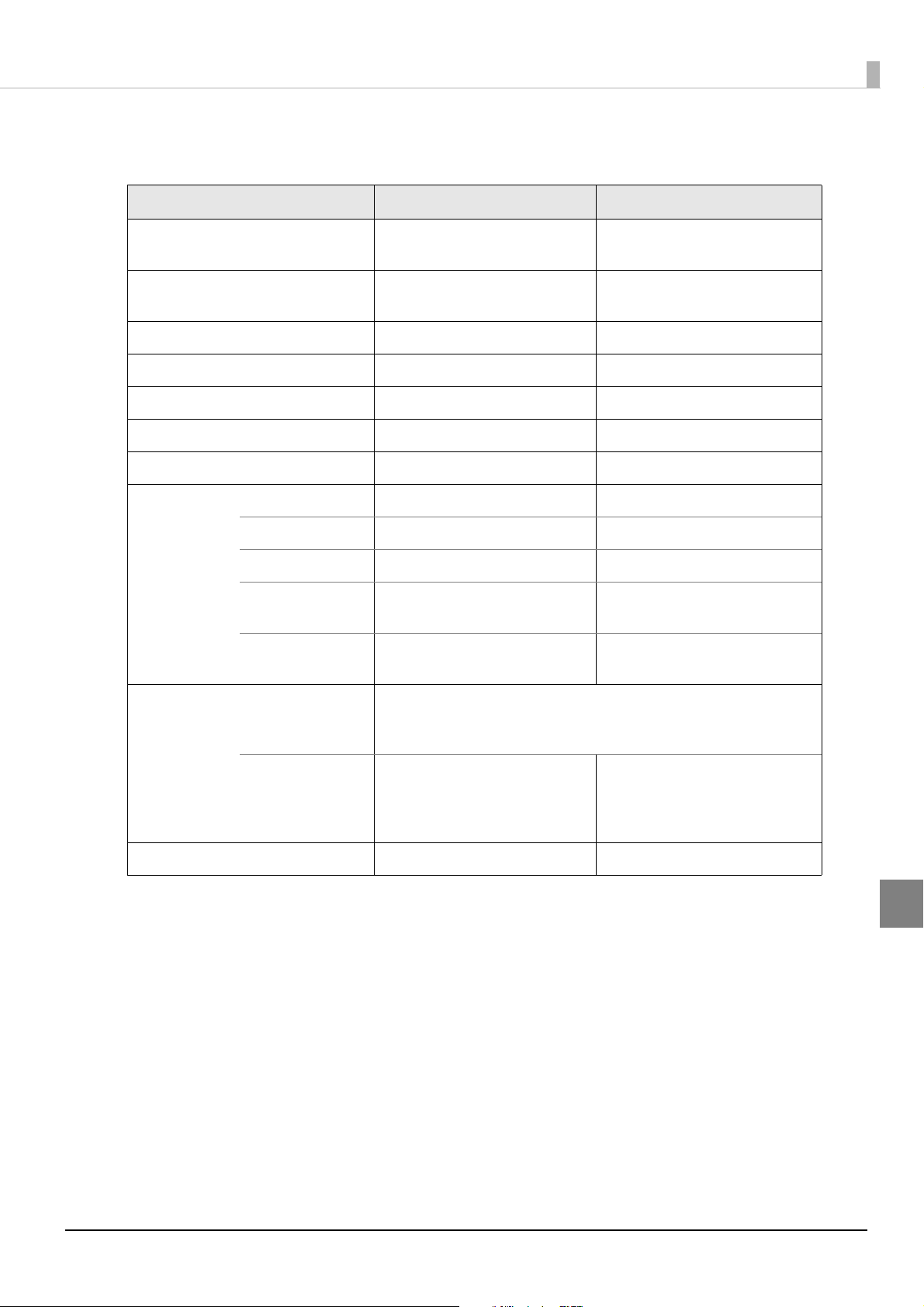
Chapter 6 Replacement of the TM-P60
Additional Functions and Functional Improvements
TM-P60 TM-P60II
Print Speed MAX. 80 mm/s
(receipt printing)
Extended graphics (including userdefined page)
International characters 16 sets 18 sets
Battery life (Bluetooth models) Approx. 20 hours Approx. 56 hours
Mass (including the battery) Approx. 640 g Approx. 613 g
Battery charge LED Not available Orange LED
EPSON TM Virtual Port Driver Not available Available
Utilities TM-P60II Utility Not available Available
EpsonNet Config Not available Available
Monitoring Tool Not available Available
TM-P60II Remote
Configuration Tool
TM Bluetooth
nector
® Con-
128 × 10 pages 128 × 43 pages
Not available Available
Not available Available
MAX. 100 mm/s
(receipt printing)
Barcode printing
Automatic reduction of paper Not available Available
1D UPC-A, UPC-E, JAN13/EAN13, JAN8/EAN8, CODE39, ITF, CODABAR,
CODE93, CODE128, GS1-128, GS1 DataBar Omnidirectional, GS1 DataBar
Truncated, GS1 DataBar Limited, GS1 DataBar Expanded
2D PDF417, MaxiCode, QR Code, Com-
posite Symbology, Two-dimensional GS1 DataBar
PDF417, MaxiCode, QR Code, Composite Symbology, Two-dimensional GS1 DataBar, Aztec Code,
DataMatrix
6
85

Appendix
Product Specifications
Printing Specifications
Printing method Thermal line printing
Dot density 203 × 203 dpi
Feeding method Friction feed
Paper width*
Printing width 54.0 mm {2.13"} maximum, 432 dots (when the paper width is 60 mm)
Characters per line Font A: 36
Maximum print speed*
Paper feed speed*
Line spacing*
dpi: dots per inch
*1: Receipt paper with a width of 58 mm or 60 mm can be used.
*2: Only for Traditional Chinese Model.
*3: The printing speed listed above are the values when using a new battery fully charged, the print density is 100%, and at normal
temperature. The printing speed changes automatically depending on power supply voltage and the condition of the head tem-
perature. Receipt and label printing can be changed by setting the paper layout.
*4: With label printing, peeler issuing and continuous issuing modes change automatically depending on the peeler use conditions.
*5: Initial setting. Programmable by commands.
1
3
4
5
29.5 mm {1.16"}, 36 mm {1.82"}, 42 mm {1.65"}, 48.5 mm {1.91"}, 55 mm {2.17"}, 58
mm {2.28"} (default), 60 mm {2.36"}
48.5 mm {1.91"} dots, 388 dots (when the label width is 54 mm and the paper width
of the backing paper (liner) is 58 mm)
Font B: 43
Font C: 54
Kanji font*
100 mm/s {3.94"/s} (receipt printing)
80 mm/s {3.15"/s} (label continuous issuing mode)
40 mm/s {1.57"/s} (label peeler issuing mode)
40 mm/s {1.57"/s} (ladder bar code and 2-dimensional symbols printing)
100 mm/s {3.94"/s} (receipt printing)
80 mm/s {3.15"/s} (label continuous issuing mode)
40 mm/s {1.57"/s} (label peeler issuing mode)
3.75 mm {0.15"}
2
: 18
86

• For changing the paper width, see "Changing the Paper Width" on page 30.
• Printing speed may be slower, depending on the data transmission speed and the
combination of control commands.
Character Specifications
Number of characters Alphanumeric characters: 95
Extended graphics: 128 × 43 pages (including user-defined page)
International characters: 18 sets
Traditional Chinese*
Character structure Font A: 12 × 24
Font B: 10 × 24 (Initial setting)
Font C: 8 × 16
Kanji font*
1
: 24 × 24
1
: Big5 13,535
Appendix
Character size
(Standard/
Double-height/
Double-width/)
W × H
(mm)*
3
cpl*
Font A: 1.5 × 3.0/1.5 × 6.0/3.0 × 3.0
2
Font B: 1.25 × 3.0/1.25 × 6.0/2.5 × 3.0
Font C: 1.0 × 2.0/1.0 × 4.0/2.0 × 2.0
Kanji font*
1
: 3.0 × 3.0/3.0 × 6.0/6.0 × 3.0
Font A: 36/36/18
Font B: 43/43/21
Font C: 54/54/27
Kanji font*
1
: 18/18/9
*1: Only for Traditional Chinese Model.
*2: The actual print character may be smaller than the size shown in the table above because the above size includes spaces in the
font.
*3: The “characters per line” shows the value of receipt printing when the paper width is 60 mm {2.36"}.
cpl: Characters per line
87

Paper Specifications
Type Thermal paper:
Die-cut label paper (without black mark)
Die-cut label paper (with black mark)
Receipt paper (without black mark)
Receipt paper (with black mark)
Form Roll paper
Size Width*
*1: Receipt paper with a width of 58 mm or 60 mm can be used.
1
Outside diameter 51.0 mm {2.01"} maximum
Roll width when takenup29.5 mm paper width: 29.5 + 0/-1.0 mm {1.16 + 0/- 0.04"}
Roll paper core Outside diameter (die-cut label): 31.4 mm {1.24"} or more
29.5 mm paper width: 29.0 ± 0.5 mm {1.14 ± 0.02"}
36.0 mm paper width: 35.5 ± 0.5 mm {1.40 ± 0.02"}
42.0 mm paper width: 41.5 ± 0.5 mm {1.63 ± 0.02"}
48.5 mm paper width: 48.0 ± 0.5 mm {1.90 ± 0.02"}
55.0 mm paper width: 54.5 ± 0.5 mm {2.15 ± 0.02"}
58.0 mm paper width: 57.5 ± 0.5 mm {2.26 ± 0.02"}
60.0 mm paper width: 59.5 ± 0.5 mm {2.34 ± 0.02"}
36.0 mm paper width: 36.0 + 0/-1.0 mm {1.82 + 0/- 0.04"}
42.0 mm paper width: 42.0 + 0/-1.0 mm {1.65 + 0/- 0.04"}
48.5 mm paper width: 48.5 + 0/-1.0 mm {1.91 + 0/- 0.04"}
55.0 mm paper width: 55.0 + 0/-1.0 mm {2.17 + 0/- 0.04"}
58.0 mm paper width: 58.0 + 0/-1.0 mm {2.28 + 0/- 0.04"}
60.0 mm paper width: 60.0 + 0/-1.0 mm {2.36 + 0/- 0.04"}
Outside diameter (receipt): 18 mm {0.71"} or more
Specified original paper type
Paper type Paper type no. Manufacturer
Die-cut label DTM9502
(label paper: KL370 or KIP37032)
Receipt P30023, P31023, P35024 Kanzaki Specialty Papers (USA)
• Paper must not be pasted to the roll paper spool.
• For the best print quality for each paper type, it is recommended to set the print density. The
print density can be set with the customized value. To set customized value, See
Settings" on page 48
• Be sure to use the specified paper.
A red line that indicates the paper end is recommended to be preprinted on the end of the roll
paper.
.
MACtac
(Kanzaki Specialty Papers (USA))
88
"Software

Requirement for die-cut label (without black mark)
Die-cut label length =
25.4 - 150 mm
Die-cut label interval = 28.4- 153mm
Dimension of liner portion between die-cut labels = 3
± 0.5 mm (gap between labels)
Die-cut label length =
25.4 - 150 mm
Die-cut label interval = 28.4- 153mm
Dimension of liner portion between die-cut labels = 3
± 0.5 mm (gap between labels)
The gap between the top/bottom of a black mark and
the top/bottom of a die-cut label must be 0.5 mm or
less.
Black mark must be printed on the reverse left side.
Appendix
Requirement for die-cut label (with black mark)
89

Requirement for black mark printing
(2) Reverse side
(1) Reverse side
Reverse side preprintable area
15 or more
30 - 150
3 - 5
Paper feed direction
[Units: mm]
The allowable relation between the reflecting rate in the black mark portion (1) and the non black mark portion
(2) must be as shown in the table below:
Allowable combination of the reflecting rate [units: %]
Black mark portion (1) 17 16 15 14 13 or less
Black mark portion (2) 90 85 80 75 70 or more
The reflecting rate means the value which is measured with a Macbeth density meter (PCMII) D
filter.
90

Printable Area
[Units: mm]
Printable area
Printable area
[Units: mm]
Printable area
Printable area
Die-cut label paper
Example: Liner width: 57.5 mm/Label width: 54 mm
Appendix
Example: Liner width: 59.5 mm/Label width: 56 mm
The printable area may be out of alignment by 2.8 mm {0.11"} maximum (left or right), due to the
paper position or tolerance of parts. To make the margin for both sides safely, it is recommended
to set a margin of 2.8 mm {0.11"} or more.
91

Liner width and printable area (recommended)
Liner width (mm) 60 58 55 48.5 42 36 29.5
Liner width (design value) (mm) 5 9. 5 ±
0.5
Label width (mm) 56 54 51 44.5 38 32 25.5
Printable area (mm) 50 48.5 45 39 32 26 20
Liner paper edge - label edge (left) 1.75 1.75 1.75 1.75 1.75 1.75 1.75
Liner paper edge - label edge
(right)
Left margin (mm) 3 3 3 3 3 3 3
Right margin (mm) 3 2.5 3 2.5 3 3 2.5
Positioning dot number 1 7 t o
Characters per line Font A 33 32 30 26 21 17 13
Font B 40 38 36 31 25 20 16
Font C 50 48 45 39 32 26 20
It is assumed that the label is placed on the center of the liner exactly. Numeric values used here are average values for designing.
1.75 1.75 1.75 1.75 1.75 1.75 1.75
416
57.5 ±
0.5
17 to
404
54.5 ±
0.5
17 to
376
48.0 ±
0.5
17 to
328
41.5 ±
0.5
17 to 272 1 7 t o
35.5 ±
0.5
224
29.0 ±
0.5
17 to
176
92

Receipt paper
Dot 1
(2.75 mm)
(2.25 mm)
52 mm (Dot 1 - 420)
Dot 420
0.125 mm
57.5 0.5 mm
(2.75 mm)
(2.75 mm)
54 mm (Dot 1 - 432)
Dot 432
0.125 mm
59.5 0.5 mm
Printing is automatically performed in one to four-part energization depending on the printing
conditions. During printing with two to four-part energization, a maximum misalignment
(horizontal ruled line shift) of 1/4 to 1/2 dot might occur in the paper feeding direction due to
segmented printing.
58 mm width paper printing
Appendix
60 mm width paper printing
93

Paper width and printable area
Paper width (mm) 60 58
Paper width (design value) (mm) 59.5 ± 0.5 57.5 ± 0.5
Printable area (mm) 54 52.5
Left margin (mm) 2.75 2.75
Right margin (mm) 2.75 2.25
Positioning dot number 1 to 432 1 to 420
Total number of dots 432 420
Characters per line Font A 36 35
Font B 43 42
Font C 54 52
Numeric values used here are average values for designing.
94

Printing and Cutting Positions
When a peeler is used: Label
When a label is issued continuously: Liner + Label or receipt
Label peeler sensor
Peeler shaft
Peeler roller
When a peeler is used: Liner
When a label is issued continuously: Nothing
is fed
Platen
Manual cutter
Reflecting photosensor
Transmissive photosensor
Approx. 15 mm
Platen head
A
p
p
r
o
x
.
8
.
5
m
m
A
p
p
r
o
x
.
1
4
m
m
A
p
p
r
o
x
.
3
.
5
m
m
Peeling position
Appendix
Numeric values used here are typical values. The values above may vary slightly as a result of
paper slack or variations in the paper. Take this into account when setting the manual cutting
position.
95

Electrical Characteristics
• Be sure to install the battery in the printer. The printer does not operate with the AC adapter
only.
• Be sure to use the optional PS-11 as the AC adapter.
Dedicated battery
(OT-BY60II)
Power supply Input: DC24 V/Max. 1.5 A or DC12 V/Max. 1.0 A*
Dedicated AC adapter
(PS-11)
Consumption During standby: 0.3 W/230 V, when using PS-11
Continuous operating
time
*: This is the input voltage required to charge the battery with the printer.
Model: D141A Rated voltage: DC 7.4 V
Capacity: 2000 mAh
Model: D161A Rated voltage: DC 7.2 V
Capacity: Typ. 1950 mAh, Min. 1850 mAh
Output: DC 24 V/Max. 1.5 A
Input: AC 100 V to 240 V
During charging: 15 W/230 V, when using PS-11
Wi-Fi models Power save mode enabled: approx. 34 hours
Power save mode disabled: approx. 15 hours
Bluetooth models Approx. 56 hours
Above continuous operating times will vary depending on changes in the use environment or
condition.
96

Reliability
1
Life*
Appendix
Printer mechanism When printing labels: 500,000 labels issued (When the length of the label
in the paper feeding direction is 25.4 mm {1"} through 100 mm {3.94"}. The
value above corresponds to approximately 14 km to 50 km {8.71 to 31.1
miles] of running length. When printing labels whose length exceeds 100
mm, the label-issuing life is 50 km {31.1 miles} of running length.
When printing receipts: 10,000,000 lines printed (3.75 mm {0.15"} for one
line) (When the value above is calculated, the printer uses 26-line feeding
and 20-line printing repeatedly. This corresponds to approximately 50 km
of running length.)
Thermal head 100 million pulses (for each element)
MTBF (Mean Time Between Failure)*
MCBF (Mean Cycle Between Failure)*
Depending on the paper condition, paper or glue may stick to the thermal head, platen, or peeler
holder. The reliability values listed above are given for the condition of performing cleaning after
every 20,000 label issued (label length: 25.4 mm).
*1: End of life is defined as the point at which the printer reaches the beginning of the wear out period.
*2: Failure is defined as a random failure occurring at the time of the random failure period.
*3: This is an average failure interval based on failures related to wear out and random failures up to the life of 10 million lines.)
2
120,000 hours
3
16 million lines
97

Environmental Conditions
Temperature and humidity
For operation When using only battery for
power supply
When using battery and AC
adapter for power supply
For print quality When using only battery for
power supply
When using battery and AC
adapter for power supply
For battery charging Temperature: 0 to 40°C {32 to 104°F}
Storage at high temperature and high humidity Temperature: 45°C {113°F}
Storage at high temperature Temperature: 70°C {158°F}
Storage at low temperature Temperature: -25°C {-13°F}
Temperature: 0 to 45°C {32 to 113°F} (except for print quality)
Humidity: 10 to 90% RH (except for paper)
Temperature: 0 to 40°C {32 to 104°F} (except for print quality)
Humidity: 10 to 90% RH (except for paper)
Temperature: 5 to 45°C {41 to 113°F}
Humidity: 10 to 90% RH
Temperature: 5 to 40°C {41 to 104°F}
Humidity: 10 to 90% RH
Humidity: 10 to 90% RH
Humidity: 90% RH
Storage time: 120 hours
Storage time: 120 hours
Storage time: 120 hours
Acoustic noise
During operation Approximately 50 dB (bystander position)
Note:
The values above are measured in the Epson evaluation
condition.
Acoustic noise differs depending on the paper used, printing contents, and the setting values, such as print speed or
print density.
If the printer is not used for a long time with paper installed, some part of the printing may be
light due to the deformation of the paper. If the printer is not used for a long time with paper
installed, be sure to feed paper approximately 30 mm {1.18"} before printing.
98

External Dimensions and Mass
103
159
65
[Units: mm]
• Width: Approximately 103 mm {4.06"}
• Depth: Approximately 159 mm {6.26"}
• Height: Approximately 65 mm {2.56"} (the belt clip excluded)
• Mass: Approximately 613 g {1.35 lb} (the battery and belt clip included; roll paper excluded)
Appendix
Colors
EBCK (Epson Black)
99
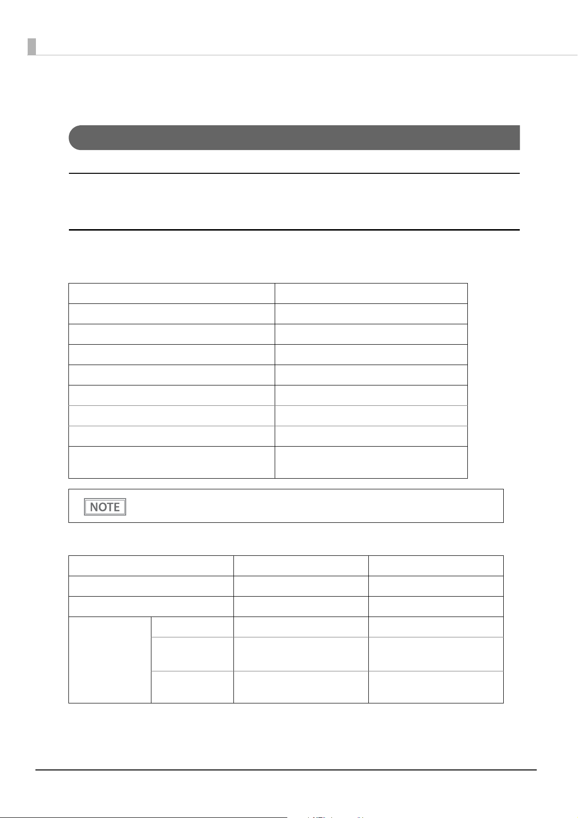
Specifications of Interfaces and Connectors
USB Interface
USB interface connector
Has a USB connector (mini USB type-B connector)
USB transmission specifications
USB function
Overall specifications According to USB 2.0 specifications
Transmission speed USB Full-Speed (12 Mbps)
Transmission method USB bulk transmission method
Power supply specifications USB self power supply function
Current consumed by USB bus 2 mA
USB packet size (with full-speed connection)
USB bulk OUT (TM) 64 bytes
USB bulk IN (TM) 64 bytes
USB device class Both USB vendor-defined class and USB printer
class are supported.
To set the USB device class, see
"Software Settings" on page 48.
USB descriptor
USB vendor-defined class USB printer class
Vendor ID 04B8h 04B8h
Product ID 0202h 0E0Eh
String Descriptor Manufacturer EPSON EPSON
Product TM-P60IIPeeler Wi-Fi
TM-P60IIPeeler Bluetooth
TM-P60IIPeeler Wi-Fi
TM-P60IIPeeler Bluetooth
100
Serial number Character string based on the
product serial number
Character string based on the
product serial number
 Loading...