

Page 1
SERVICE MANUAL "ECOS"
Scanner•Printer•Copier
EPSON Stylus Photo RX700
Page 2

Notice
All rights reserved. No part of this manual may be reproduced, stored in a retrieval system, or transmitted in any form or by any means electronic, mechanical,
photocopying, or otherwise, without the prior written permission of SEIKO EPSON CORPORATION.
All efforts have been made to ensure the accuracy of the contents of this manual. However, should any errors be detected, SEIKO EPSON would greatly
appreciate being informed of them.
The contents of this manual are subject to change without notice.
The above not withstanding SEIKO EPSON CORPORATION can assume no responsibility for any errors in this manual or the consequences thereof.
EPSON is a registered trademark of SEIKO EPSON CORPORATION.
General Notice: Other product names used herein are for identification purpose only and may be trademarks or registered trademarks of their
respective owners. EPSON disclaims any and all rights in those marks.
Copyright © 2004 SEIKO EPSON CORPORATION.
I&I CS Quality Promotion Dept.
(Printer Technical Support Grp.)
Imaging & Information Products Div.
Page 3

PRECAUTIONS
Precautionary notations throughout the text are categorized relative to 1)Personal injury and 2) damage to equipment.
DANGER Signals a precaution which, if ignored, could result in serious or fatal personal injury. Great caution should be exercised in performing procedures preceded by
DANGER Headings.
WARNING Signals a precaution which, if ignored, could result in damage to equipment.
The precautionary measures itemized below should always be observed when performing repair/maintenance procedures.
DANGER
1. ALWAYS DISCONNECT THE PRODUCT FROM THE POWER SOURCE AND PERIPHERAL DEVICES PERFORMING ANY MAINTENANCE OR REPAIR PROCEDURES.
2. NO WORK SHOULD BE PERFORMED ON THE UNIT BY PERSONS UNFAMILIAR WITH BASIC SAFETY MEASURES AS DICTATED FOR ALL ELECTRONICS
TECHNICIANS IN THEIR LINE OF WORK
3. WHEN PERFORMING TESTING AS DICTATED WITHIN THIS MANUAL, DO NOT CONNECT THE UNIT TO A POWER SOURCE UNTIL INSTRUCTED TO DO SO. WHEN
THE POWER SUPPLY CABLE MUST BE CONNECTED, USE EXTREME CAUTION IN WORKING ON POWER SUPPLY AND OTHER ELECTRONIC COMPONENTS
4. WHEN DISASSEMBLING OR ASSEMBLING A PRODUCT, MAKE SURE TO WEAR GLOVES TO AVOID INJURIES FROM METAL PARTS WITH SHARP EDGES.
.
.
WARNING
1. REPAIRS ON EPSON PRODUCT SHOULD BE PERFORMED ONLY BY AN EPSON CERTIFIED REPAIR TECHNICIAN.
2. MAKE CERTAIN THAT THE SOURCE VOLTAGES IS THE SAME AS THE RATED VOLTAGE, LISTED ON THE SERIAL NUMBER/RATING PLATE. IF THE EPSON
PRODUCT HAS A PRIMARY AC RATING DIFFERENT FROM AVAILABLE POWER SOURCE, DO NOT CONNECT IT TO THE POWER SOURCE.
3. ALWAYS VERIFY THAT THE EPSON PRODUCT HAS BEEN DISCONNECTED FROM THE POWER SOURCE BEFORE REMOVING OR REPLACING PRINTED CIRCUIT
BOARDS AND/OR INDIVIDUAL CHIPS.
4. IN ORDER TO PROTECT SENSITIVE MICROPROCESSORS AND CIRCUITRY, USE STATIC DISCHARGE EQUIPMENT, SUCH AS ANTI-STATIC WRIST STRAPS, WHEN
ACCESSING INTERNAL COMPONENTS.
5. DO NOT REPLACE IMPERFECTLY FUNCTIONING COMPONENTS WITH COMPONENTS WHICH ARE NOT MANUFACTURED BY EPSON. IF SECOND SOURCE IC OR
OTHER COMPONENTS WHICH HAVE NOT BEEN APPROVED ARE USED, THEY COULD CAUSE DAMAGE TO THE EPSON PRODUCT, OR COULD VOID THE
WARRANTY OFFERED BY EPSON.
Page 4

About This Manual
This manual describes basic functions, theory of electrical and mechanical operations, maintenance and repair procedures of the printer. The instructions and procedures included
herein are intended for the experienced repair technicians, and attention should be given to the precautions on the preceding page.
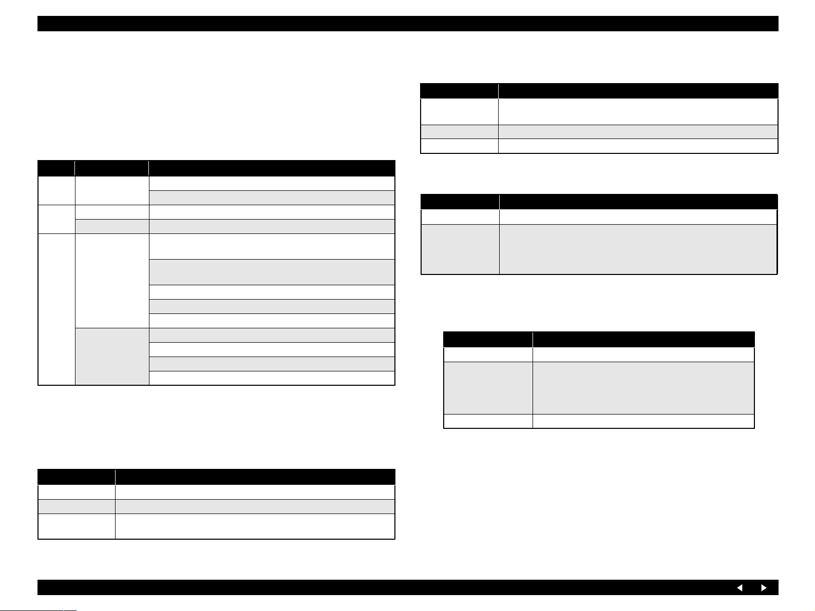
Manual Configuration
This manual consists of six chapters and Appendix.
CHAPTER 1.PRODUCT DESCRIPTIONS
Provides a general overview and specifications of the product.
CHAPTER 2.OPERATING PRINCIPLES
Describes the theory of electrical and mechanical operations of
the product.
CHAPTER 3.TROUBLESHOOTING
Describes the step-by-step procedures for the troubleshooting.
CHAPTER 4.DISASSEMBLY / ASSEMBLY
Describes the step-by-step procedures for disassembling and
assembling the product.
CHAPTER 5.ADJUSTMENT
Provides Epson-approved methods for adjustment.
CHAPTER 6.MAINTENANCE
Provides preventive maintenance procedures and the lists of
Epson-approved lubricants and adhesives required for servicing
the product.
APPENDIX Provides the following additional information for reference:
• Connection with Connectors
• Circuit Boards Component Layout
• Exploded diagram & Parts List
Symbols Used in this Manual
Various symbols are used throughout this manual either to provide ad ditional
information on a specific topic or to warn of possible danger present during a
procedure or an action. Be aware of all symbols when they are used, and
always read NOTE, CAUTION, or WARNING messages.
A D J U S T M E N T
R E Q U I R E D
C A U T I O N
C H E C K
P O I N T
W A R N I N G
Indicates an operating or maintena nce procedure, practice or
condition that is necessary to keep the product’s quality.
Indicates an operating or maintenance procedure, practice, or
condition that, if not strictly observed, could result in damage to, or
destruction of, equipment.
May indicate an operating or maintenance procedure, practice or
condition that is necessary to accomplish a task efficiently. It may
also provide additional information that is related to a specific
subject, or comment on the results achieved through a previous
action.
Indicates an operating or maintena nce procedure, practice or
condition that, if not strictly observed, could result in injury or loss
of life.
Page 5

Revision Status
Revision Date of Issue Description
A May 9, 2005 First Release
B June16, 2005 Revised the following.
"Ink Cartridges" on page -15: Changed the description of print capacity and checkpoint.
"Adjustment Items" on page -134: The remained Japanese has been translated.
Page 6

EPSON Stylus Photo RX700 Revision A
CONTENTS
Chapter 1 Product Description
1.1 Overview ............................................................................................................ 10
1.1.1 Printer and PC Printing ............................................................................. 10
1.1.2 Scanner and Scanning Functions .............................................................. 11
1.1.3 Copy Functions ......................................................................................... 12
1.1.4 Interfaces ................................................................................................... 13
1.1.5 USB Host Functions ................................................................................. 13
1.1.6 LCD Function ........................................................................................... 13
1.2 Common Specifications ................................ .................................................... 14
1.2.1 Electrical Specifications ........................................................................... 14
1.2.2 Environmental Resistance ........................................................................ 14
1.2.3 Durability .................................................................................................. 15
1.2.4 Noise ......................................................................................................... 15
1.2.5 Weight and Shape ..................................................................................... 15
1.2.6 Ink Cartridges ........................................................................................... 15
1.3 Special Operations ................................... ......................................................... 16
1.3.1 Operation for Forced Power Off ............................................................... 16
Chapter 2 Operating Principles
2.1 Overview ............................................................................................................ 18
2.1.1 Mechanical Components .......................................................................... 18
2.1.2 Motors and Sensors ................................................................................... 19
2.2 Mechanism Operating Principles .................................................................... 21
2.2.1 Printhead ................................................................................................... 21
2.2.2 Carriage Mechanism ................................................................................. 22
2.2.2.1 CR Motor Specifications .................................................................. 22
2.2.2.2 PW Sensor ......................................................................................... 22
2.2.3 APG Mechanism ....................................................................................... 23
2.2.3.1 APG Motor Specifications ................................. ............................... 23
2.2.3.2 APG Sensor ....................................................................................... 23
2.2.3.3 APG Driving Transmission ............................................................... 24
2.2.3.4 Driving Specifications ....................................................................... 25
2.2.4 Paper Feed Mechanism ............................................................................. 26
2.2.4.1 PF Motor Specifications .................................................................... 26
2.2.4.2 PF Encoder ........................................................................................ 26
2.2.4.3 PE Detector ....................................................................................... 27
2.2.4.4 Transmission Path of Driving Force for Paper Feed ......................... 27
2.2.5 CD-R Mechanism ..................................................................................... 28
2.2.5.1 CD-R Sensor 1 (for Guide) ............................................................... 28
2.2.5.2 CD-R Sensor 2 (for Tray) ............................................ ...................... 28
2.2.5.3 CD-R Mechanism Explanation ......................................................... 29
2.2.6 Paper Loading Mechanism ....................................................................... 30
2.2.6.1 ASF Motor ......................................................................................... 30
2.2.6.2 Cover Tray Detector .......................................................................... 30
2.2.6.3 Transmission Path of Driving Force for the Paper Loading Mechanism
31
2.2.7 Outline of Paper Path ................................................................................ 34
2.2.8 Ink Supply System .................................................................................... 36
2.2.8.1 I/C Cover Opening/Closing Switch ................................................... 36
2.2.8.2 Self-closing Valve ............................................................................. 37
2.2.9 Pressure Pump Mechanism ....................................................................... 38
2.2.9.1 Pressure Pump Motor ........................................................................ 38
2.2.9.2 Pressure Sensor ................................................................................. 38
2.2.9.3 Pump HP Sensor ................................................................................ 39
2.2.9.4 Driving Specifications ....................................................................... 39
2.2.10 Ink System .............................................................................................. 40
2.2.10.1 Pump Motor ..................................................................................... 40
2.2.10.2 Ink System Driving Conditions ....................................................... 40
2.2.11 Scanner Unit ........................................................................................... 41
2.2.11.1 CR Motor ......................................................................................... 42
2.2.11.2 HP Sensor ........................................................................................ 42
2.3 Operating Principles of Electric Circuitry ..................................................... 43
2.3.1 Overview .................................................................................................. 43
6
Page 7

EPSON Stylus Photo RX700 Revision A
2.3.2 Features ..................................................................................................... 43
2.3.3 Main Board ............................................................................................... 44
2.3.3.1 Outline of the Main Board ................................................................. 44
2.3.3.2 Environmental Conditions ................................................................. 44
2.3.3.3 Power Supply Specifications ............................................................. 44
2.3.3.4 Main Board Circuit Configuration (Printer and Common Section) .. 45
2.3.3.5 Main Board Circuit Configuration (Card Section) ............................ 46
2.3.3.6 Main Board Circuit Configuration (Scanner Section) ....................... 47
2.3.4 Panel Board ............................................................................................... 47
2.3.5 Power Supply Board ................................................................................. 48
2.3.5.1 Circuit Constitution ........................................................................... 48
2.3.5.2 Input and Output Specifications ........................................................ 48
2.3.5.3 General Specifications ....................................................................... 50
Chapter 3 Troubleshooting
3.1 Overview ............................................................................................................ 52
3.1.1 Specified Tools ......................................................................................... 52
3.1.2 Preliminary Checks ................................................................................... 52
3.1.3 Procedure for Troubleshooting ................................................................. 53
3.1.4 Error List ................................................................................................... 54
3.1.5 Warning List ............................................................................................. 57
3.1.6 FATAL Error ............................................................................................ 59
3.2 Troubleshooting for Printer ............................................................................ 65
3.3 Power Supply Related Troubleshooting ......................................................... 69
3.4 Ink Supply Related Troubleshooting .............................................................. 70
3.5 I/F Related Troubleshooting ............................................................................ 72
3.6 Troubleshooting for Scanner ........................................................................... 73
3.7
Troubleshooting for Motors and Sensors ............................................... 75
Chapter 4 Disassembly and Assembly
4.1 Overview ............................................................................................................ 77
4.1.1 Precautions ................................................................................................ 77
4.1.2 Tools ......................................................................................................... 78
4.1.3 Preparation before Disassembly ............................................................... 78
4.1.4 Disassembly and Reassembly Procedure .................................................. 79
4.2 Removal of Exterior Parts ............................................................................... 80
4.2.1 Panel Assy ................................................................................................ 80
4.2.1.1 LCD Assy .......................................................................................... 81
4.2.1.2 Disassembly of LCD Assy ................................................................ 81
4.2.1.3 Disassembly of Panel Assy ............................................................... 82
4.2.2 Scanner Unit ............................................................................................. 83
4.2.3 Pressure Pump Assy ................................................................................. 85
4.2.4 Main Board Unit ....................................................................................... 86
4.2.5 Middle Housing ........................................................................................ 88
4.2.6 Linear Scale ...................................... ........................................................ 91
4.2.7 Printhead ................................................................................................... 92
4.2.8 Valve Assy (Including Ink Tube Assy) .................................................... 94
4.3 Disassembly of Scanner Unit ........................................................................... 96
4.3.1 Disassembly Procedure for Scanner Unit ................................................. 96
4.3.2 Scanner Housing ....................................................................................... 97
4.3.3 HP Board ................................................................................................ .. 98
4.3.4 Carriage Cover Assy ................................................................................. 98
4.3.5 CR Motor Unit .......................................................................................... 99
4.3.6 CCD Unit (Carriage Unit Assy) ........................... .................................. 100
4.3.7 Disassembly of TPU Assy ...................................................................... 101
4.4 Disassembly and Assembly of Major Parts of Printer ................................ 102
4.4.1 ASF Rear Assy .............................. ......................................................... 103
4.4.2 I/C Holder Assy ............................................................ .......................... 105
4.4.3 Waste Ink Pads (I/C Holder Assy) ......................................................... 106
4.4.4 Printer Mechanism .................................................................................. 107
4.4.5 Power Supply Board ............................................................................... 109
4.4.6 Waste Ink Pads (Lower Case) ................................................................ 110
4.4.7 APG Assy ............................................................................................... 111
4.4.8 Ink System Assy ..................................................................................... 112
4.4.9 ASF Drive Assy ...................................................................................... 113
4.4.10 Rear Paper Guide Assy ......................................................................... 114
4.4.11 CR Motor .............................................................................................. 115
4.4.12 Carriage Assy ....................................................................................... 116
4.4.12.1 Assembly of Carriage Assy ........................................................... 117
4.4.12.2 Disassembly of Carriage Assy ...................................................... 118
4.4.13 Paper Guide Front Assy (Platen) .......................................................... 119
4.4.14 Waste Ink Pads (Platen Area) ............................................................... 120
4.4.15 Release Assy ......................................................................................... 121
4.4.16 PE Sensor Assy ..................................................................................... 122
4.4.17 Upper Paper Guides .............................................................................. 123
7
Page 8

EPSON Stylus Photo RX700 Revision A
4.4.18 Idle Roller Shaft Assy ........................................................................... 124
4.4.19 PF Motor ............................................................................................... 125
4.4.20 PF Roller Assy & PF Encoder Assy ..................................................... 126
4.4.21 CD-R Guide Assy ............................................................ ... .................. 127
4.4.21.1 Assembly of CD-R Guide Assy .................................................... 128
4.4.21.2 Checking of CD-R Guide Assy ..................................................... 129
4.4.22 EJ Frame Assy ...................................................................................... 130
4.4.22.1 Assembly of EJ Frame Assy ......................................................... 131
4.4.22.2 Checking of EJ Frame Assy .......................................................... 131
4.4.23 ASF Pick Up Shaft Assy ....................................................................... 132
Chapter 5 Adjustment
5.1 Overview .......................................................................................................... 134
5.1.1 Adjustment Items .................................................................................... 134
5.2 Mechanical Adjustment ................................................................................. 135
5.2.1 PG Adjustment ........................................................................................ 135
5.2.2 PF Belt Tension Adjustment ............................................................. ...... 138
5.2.3 FD Belt Tension Adjustment .................................................................. 139
5.3 Adjustments by Adjustment Program .......................................................... 140
5.3.1 Overview ................................................................................................. 140
5.3.2 Starting the Adjustment Program ..................................................... 141
5.4 Scanner Home Position Adjustment ............................................................. 142
5.4.1 Overview ................................................................................................. 142
5.4.2 Preparations for Use of the Adjustment Program ................................... 142
5.4.3 Home Position Adjustment Procedure .................................................... 143
5.4.4 Home Position Confirmation Procedure ............................................. .... 144
5.5 Uploading Firmware ...................................................................................... 145
5.5.1 Overview ................................................................................................. 145
5.5.2 Upload Procedure ................................................................................... 145
6.2 Cleaning ................................................................................ ... ........................ 150
6.3 Lubrication ...................................................................................................... 151
6.3.1 Designated Lubricant .............................................................................. 151
6.3.2 Lubrication Points ................................................................................... 151
Chapter 7 Appendix
7.1 Connectors ....................................... .................................. .. ........................... 164
7.1.1 Connector Assignments ................................................ .......................... 164
7.1.2 Pin Assignment ....................................................................................... 165
7.2 Component Layout ......................................................................................... 172
7.3 Electric Circuit Diagrams .............................................................................. 174
7.4 Exploded Diagrams ................................................................ ........................ 184
7.5 ASP Reference List ......................................................................................... 198
Chapter 6 Maintenance
6.1 Overview .......................................................................................................... 147
6.1.1 Maintenance Error .................................................................................. 147
6.1.1.1 Maintenance counters ...................................................................... 148
6.1.1.2 Waste Ink Absorption Capacity ...................................................... 149
6.1.2 Consumables and Regular Replacement Parts ....................................... 149
8
Page 9

PRODUCT DESCRIPTION
CHAPTER
1
Page 10
EPSON Stylus Photo RX700 Revision B
1.1 Overview
Stylus Photo RX700, incorporating a color inkjet printer, image scanner and memory
card slot, is provided with the following functions.
Printing: The product works as a PC printer as well as a standalone printer
that directly prints image data in the memory card inserted to the
card slot.
And the product works as a CD-R/DVD±R printing.
Image scanning: The product works as a PC image scanner. It can also save
acquired image to the memory card inserted to the memory card
slot of the product.
A film scanning function with the TPU (transparency unit) is
available as a standard feature.
Copying: The product works as a standalone copier.
Memory card slot:
The memory card slot can be used as a USB memory card slot
for a PC.
Color LCD: The color LCD is incorporated as a standard component for easy
operation.
USB Host: Data in storage devices can be printed.
Memory card information can be backed up into a storage
device.
Bluetooth or IrDA wireless connection is available as an
optional feature.
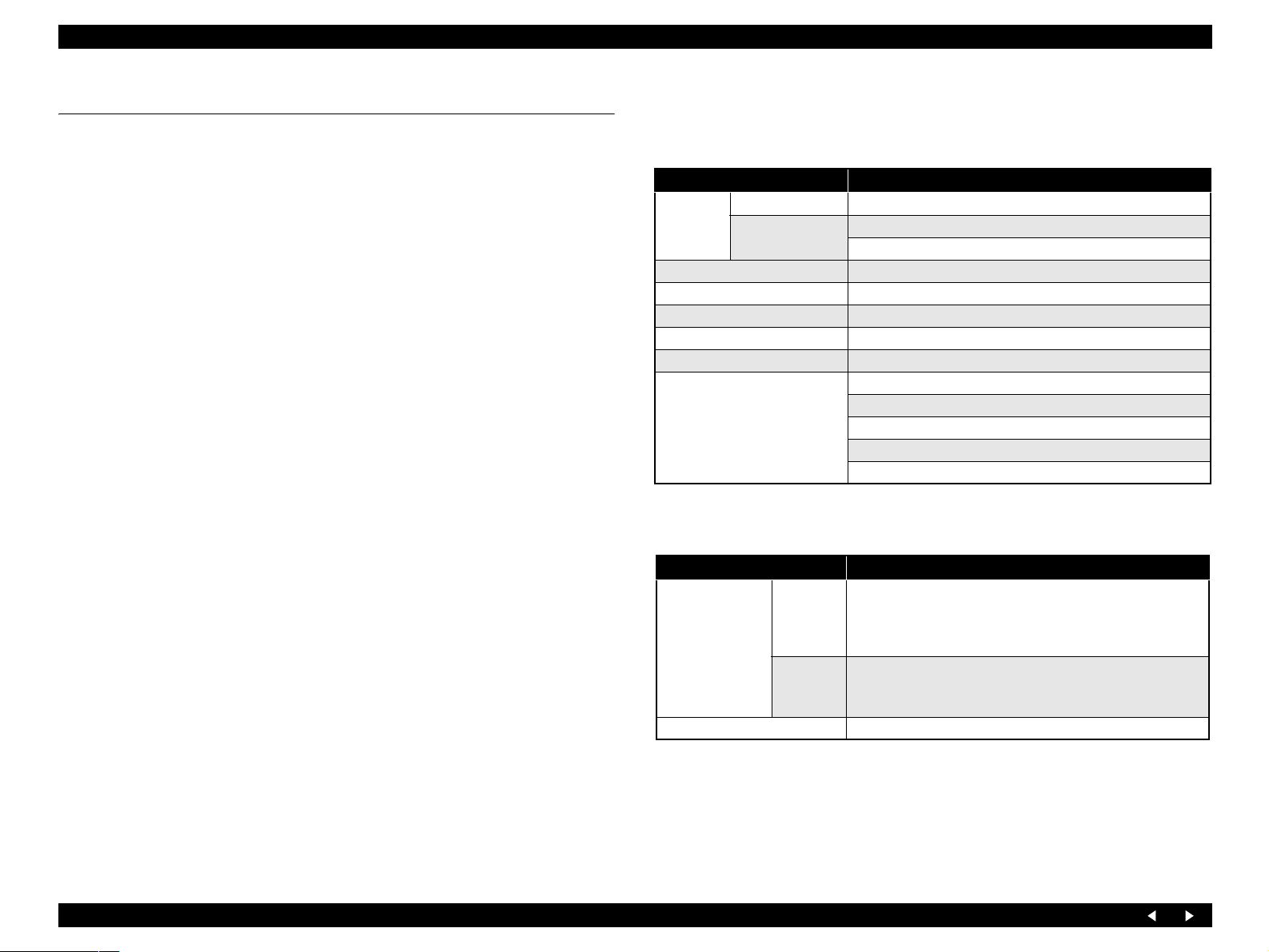
1.1.1 Printer and PC Printing
Basic specifications
Table 1-1. Printer Basic Specifications
Items Specifications
Type F-Mach
Print Head
Number of inks 6 colors
Colors of inks Black, Cyan, Magenta, Yellow, Light-Cyan, Light-Magenta
Type of ink Black & Color: HQ4
Maximum print resolution 5760 x 1440 dpi
Minimum size of dot 1.5 pl
Other functions and goals Preferred Color
Number of nozzles
Paper inputs
Table 1-2. Paper Loading Specifications
Items Specifications
Auto Sheet Feeder Type New design
Capacity*
Other paper inputs CD-R/DVD±R (with CD Try)
Black : 180
Color : 180 x 5
BorderFree printing
Silent paper loading
Double paper path
Sensor for paper width
Front in Front out: Plain Paper, A4 (Euro) only,
Letter (EAI) only
Top in Front out: All type paper, thicker Paper)
Front ASF: Plain paper: 150 sheets
Top ASF: Plain paper: 120 sheets
PGPP: 20 sheets
Note “*”: Paper thickness = 0.1mm
Product Description Overview 10
Page 11
EPSON Stylus Photo RX700 Revision B
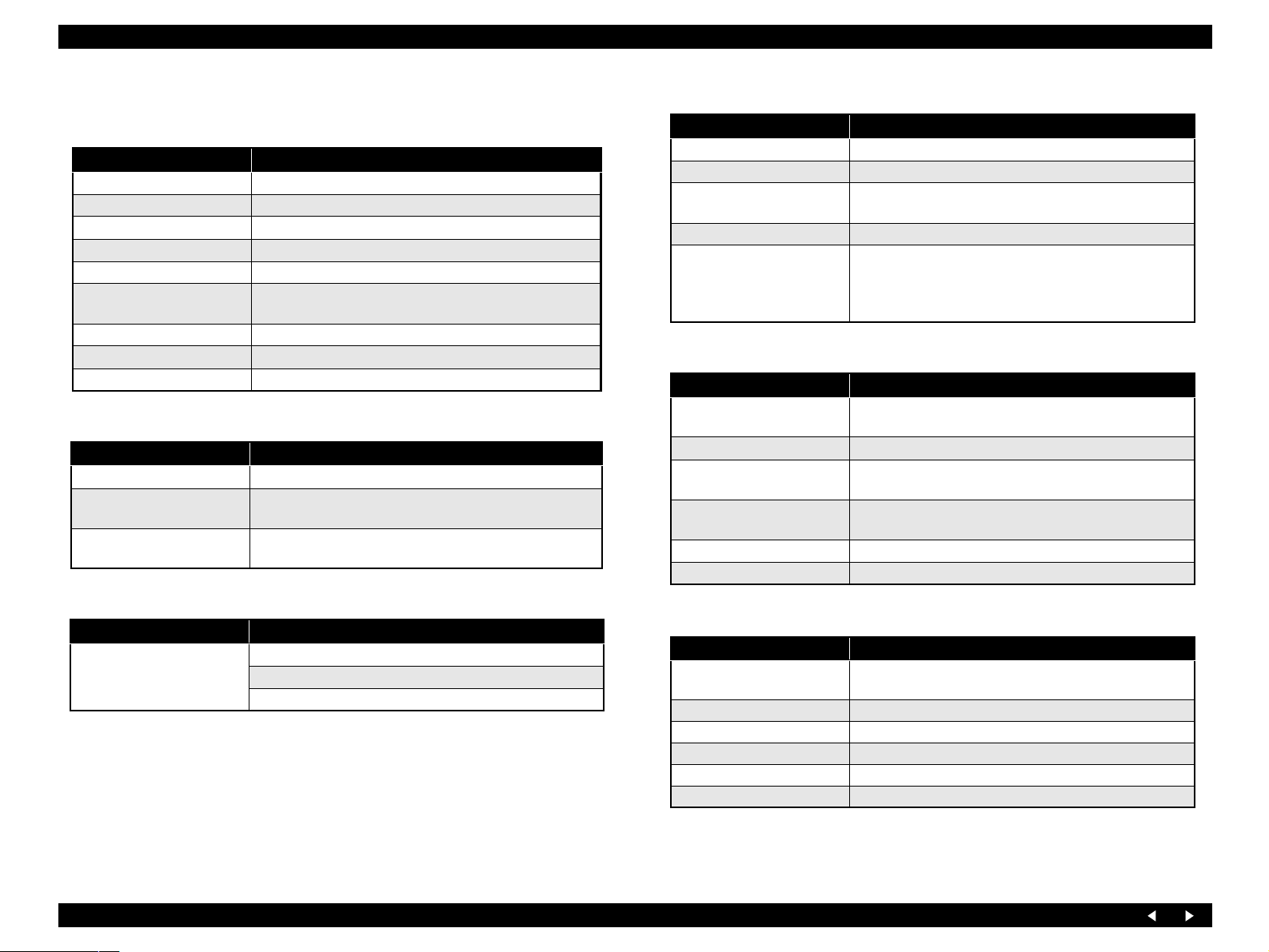
1.1.2 Scanner and Scanning Functions
Basic specifications
Items Specifications
Type Flat bed
Scan method Scanning head moving with the document fixed
Sensor Alternative 6 line color CCD
Maximum scanning size A4, US Letter
Scanning area 216 mm x 297 mm
Output resolution Main: 3200 dpi
Sub: 6400 dpi
Maximum effective pixels 27200 x 37440 pixels (3200 dpi)
Pixel depth 16-bit input and output for each pixel and each color
Light source White cold cathode fluorescent lamp
TPU
Items Specifications
Maximum document size 48 mm x 240.42 mm
Maximum number of original Strip 6 pictures
Slide 4 pictures
Film type 35 mm Color/Mono Negative Film
35 mm Color Positive Film
Scanning speed
Items Specifications
Scanning speed Mono: 4.0 ms/line (600 dpi) 25.6 ms/line (3200 dpi)
Gray: 4.0 ms/line (600 dpi) 25.6 ms/line (3200 dpi)
Full Color: 4.0 ms/line (600 dpi) 25.6 ms/line (3200 dpi)
PC scanner
Items Specifications
Interface USB 2.0 High Speed
Command level FS-D (TBD)
Scanning resolution 50 ~ 6400 dpi (selectable in 1-dpi steps), 9600dpi,
12800dpi
Gamma correction User setting: 2 levels
Special function The following software can be run and scanning operation
can be started by operation on the panel.:
Scan to E-mail
Scan to PC
Standalone scanner (Reflective document)
Items Specifications
Function Saving the acquired image from the scanner to a memory
card inserted in the memory card slot of the product
Supported memory card All the specified memory cards
Scanning area A4/Letter (maximum)
Auto crop
Document optimization Document
Photo
File format JPEG (Fixed compression ratio)
File/directory naming Automatic
Standalone scanner (Transparency)
Items Specifications
Function Saving the acquired image from the scanner to a memory
card inserted in the memory card slot of the product
Supported memory card All the specified memory cards
Scanning area TPU
Document optimization Automatic
File format JPEG (Fixed compression ratio)
File/directory naming Automatic
Product Description Overview 11
Page 12
EPSON Stylus Photo RX700 Revision B
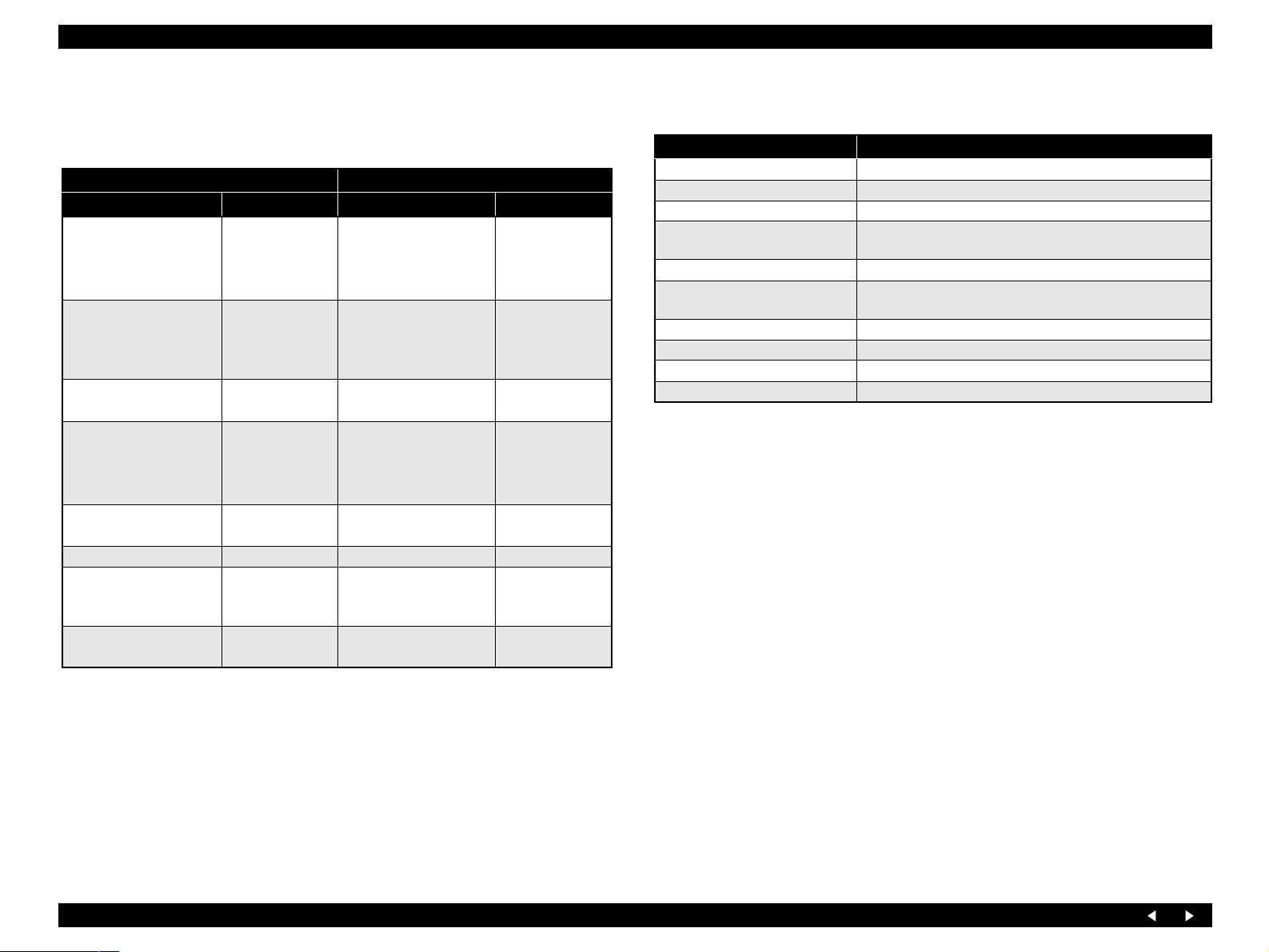
1.1.3 Copy Functions
Supported papers
Table 1-3. Supported Papers for Copy Function
EUR US
Paper Type Paper Size Paper Type Paper Size
Plain (Rear)
Plain (Front)
(Plain paper)
BrightWhite
Matte
(Matte Paper Heavy
Weight)
PQIJ
GlossyPhoto
Photo_Paper
Prem.Glossy
(Premium Photo papers)
(PGPP)
SemiGloss
Photo Stickers A6 – –
Iron On
(Iron-on cool peal Tranfer
paper)
CD-R/DVD-R Label CD Label (12 cm)
A4
A4
10x15 cm (4x6 in)
A4
10x15 cm (4x6 in)
A4
10x15 cm (4x6 in)A4SemiGloss
A4
Plain (Rear)
Plain (Front)
(Plain paper)
Matte
(Matte Paper Heavy
Weight)
GlossyPhoto
Prem.Glossy
(Premium Photo papers)
(PGPP)
Prem.Luster
Iron On
(Iron-on cool peal Tranfer
paper)
CD-R/DVD-R
Label
Letter
8x10
Letter
4x6
Letter
4x6
5x7
8x10
Letter
Letter
Letter
CD Label (12 cm)
Functions available
Table 1-4. Functions Available
Copy Function Summary
Standard copy General purpose copy mode with 3 mm margins
BorderFree copy BorderFree copying suited for making a copy of photo.
Small margins copy (Only EHC) Wider printable area provides real copy output.
Repeat copy
Poster copy (Only EHC) Enlarges an image and copies by dividing into 4, 9 or 16.
N up copy
Mirror copy (Only EHC) Prints on the Iron-On Print paper.
Wallet Photo copy (EAI only) Prints to Wallet Photo size.
CD to CD copy Prints to CD size.
Photo Stickers (Only EHC, Euro) Prints on the Photo Stickers Paper.
Provided with Auto, 4, 9, 16 and Wallet that makes multiple
small copy images on one sheet.
Copies 2 or 4 original sheets into one sheet by shrinking and
layouting them.
Product Description Overview 12
Page 13
EPSON Stylus Photo RX700 Revision B
1.1.4 Interfaces
PC Interface: USB 2.0 High Speed
Outside Interface: USB 1.1 Host
TPU Interface: 8pin MINI DIN
Memory Card Slots:
Table 1-5. Memory Card Slots
Priority Slot Support Memory Card
1 CF Type II Compact Flash (Memory card only)
MicroDrive
2 Smart Media Smart Media (max : 128MB)
xD-Picture card xD-Picture card
3 Memory Stick Memory Stick
(max : 128MB, copy protection function is not supported)
MagicGate Memory Stick
(max : 128MB, copy protection function is not supported)
Memory Stick PRO (copy protection function is not supported)
Memory Stick Duo (Adapter required)
Memory Stick Pro Duo (Adapter required)
SD/MMC SD (Secure Digital)
MiniSD (Adapter required)
Multi Media Card
RS-MMC (Adapter required)
1.1.5 USB Host Functions
Back Up function
Table 1-7. Backup Function Specifications
Items Specifications
Function Storing image data from memory card to storage drive through the USB
Host I/F.
Interface USB 1.1 Host I/F
Support device CD-R/DVD-R drive, MO drive, Zip drive
Wireless function
Table 1-8. Wireless Function Specifications
Items Specifications
Function Wireless printing from another device. (DSC etc.)
Support standard
Bluetooth : Attach the Bluetooth adapter in the USB Host I/F.
(Optional)
Wireless LAN : Attach the Tellurium to the USB2.0 FS I/F.
(Optional)
1.1.6 LCD Function
Table 1-9. LCD Function Specifications
Items Specifications
Function Displaying the information for control
Support
Others angle adjustment
Select the functions
Viewer
Slide show
Screen save
Printing function
Table 1-6. Printing Function Specifications
Items Specifications
Function Printing image data from another device through the USB Host I/F.
Interface USB 1.1
Support device USB DP, PictBrige, CD-R/DVD±R drive, MO drive, Zip drive,
USB Flash memory
Product Description Overview 13
Page 14
EPSON Stylus Photo RX700 Revision B
1.2 Common Specifications
1.2.1 Electrical Specifications
Primary power input
Table 1-10. Primary Power Input Specifications
100-120 V Model 220-240 V Model
Rated power supply voltage
(ACV)
Input voltage range (ACV) 90 ~ 132 198 ~ 240
Rated current (A) 0.8 A (max. 1.1 A) 0.4 A (max. 0.55 A)
Rated frequency (Hz) 50 ~ 60
Input frequency range (Hz) 49.5 ~ 60.5
Power consumption (W)
100-120 220-240
Approx. 25 W
(Standalone copying,
ISO10561 Letter Patter,
Plain Paper–A4 Text)
Approx. 12.5 W
(Low-power Mode)
Approx. 2.5 W (Sleep Mode) Approx. 2.5 W (Sleep Mode)
Approx. 0.2 W
(Power Off Mode)
Approx. 25 W
(Standalone copying,
ISO10561 Letter Patter,
Plain Paper–A4 Text)
Approx. 12.5 W
(Low-power Mode)
Approx. 0.4 W
(Power Off Mode)
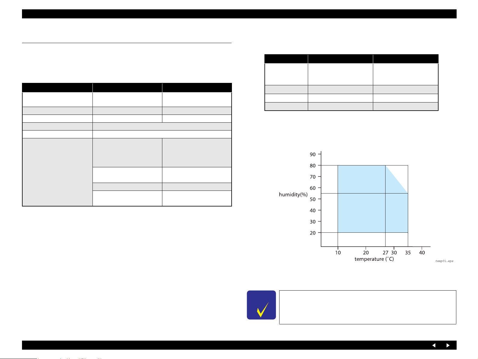
1.2.2 Environmental Resistance
Table 1-11. Environment Resistance Specifications
Item Ope ration Mode Non-operation Mode
Temperature 10 ~ 35°C *
Humidity 20 ~ 80%, RH *
Impact 1 G, 1 x 10⁻³ seconds 2 G, 2 x 10⁻³ seconds *
Vibration 0.15G 0.50G *
Note “*1”:When packed for shipping.
“*2” : No condensation
“*3”:Under the following conditions
3
2, *3
-20 ~ 60°C *
1 month when at 40°C
120 hours when at 60°C
5 ~ 85%, RH *
1
1, *2
1
1
Note 1: This product complies with the “Energy Star” standards.
2: If the printer is not operated at all for at least 5 minutes, the standby function reduces
the current to the motor to save power.
3: If the scanner is not operated at all for at least 15 minutes, the standby function reduces
the current to the motor to save power.
Insulation resistance:
10 MΩ minimum (tested between AC line and chassis, test voltage: DC 500 V)
Dielectric strength:
Figure 1-1. Environmental Conditions
AC 1000 Vrms for one minute or AC 1200 Vrms for one second
Safety Standards/EMC:
VCCI class B
Guideline for the Suppression of Harmonics in Household and General-Use
Equipment
C H E C K
P O I N T
For storage, make sure that the printhead is capped and ink
cartridges are left mounted.
Other Model-dependent Specifications: None.
Product Description Common Specifications 14
Page 15
EPSON Stylus Photo RX700 Revision B
1.2.3 Durability
Total print life : 25,000 pages (black only, A4 ),
or 10,000 color pages (A4)
or 5 years (whichever comes first)
Print head life : 6 milli on shot s (per nozzle)
or 5 years (whichever comes first)
Scanner head MCBF : 36,000 cycles
1.2.4 Noise
Noise level : max 46 dB (approx.)
(according to ISO7779 when copying)
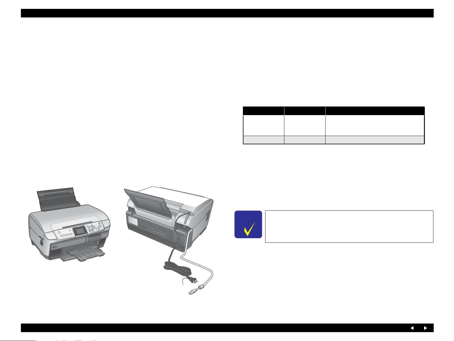
1.2.5 Weight and Shape
Weight : 12.9 kg (Excluding the ink cartridges and CD-R tray)
External dimensions (W x D x H):
Storage : 450 mm x 418 mm x 236 mm
Operation : 450 mm x 563.8 mm x 363 mm
1.2.6 Ink Cartridges
Type : Each-color separate ink cartridge
Print capacity (in pages)
Black:600pages/A4 (360dpi, 3.5% duty)
Color:450pages/A4 (360dpi, 5% duty each color)
Effective period: 6 months after unpacking; 2 years in total including 6 months
after unpacking
Storage temperature
Status Temperature Remarks
Within a month at 40°C.
Installed
Packing storage
Dimensions : 42 mm (W) x 83 mm (D) x 13 mm (H)
Weight
Refilled ink amount : 16.4+/-0.5g
Effective ink amount : 14.4 g or more
Remaining ink amount: 1.5 g or less
-20°C ~ 40°C
-30°C ~ 40°C Within a month at 40°C
An acceptable change in temperature is 45°C
or less within this range.
(25% duty continuous printing at room temperature)
C H E C K
P O I N T
Figure 1-2. External View
Product Description Common Specifications 15
The ink in the ink cartridges freezes if left in an environment of
-16°C or below. It takes approximately 3 hours before the ink
can be used, if frozen ink is moved from an environment of 20°C to that of 25°C, for example.
Page 16
EPSON Stylus Photo RX700 Revision B
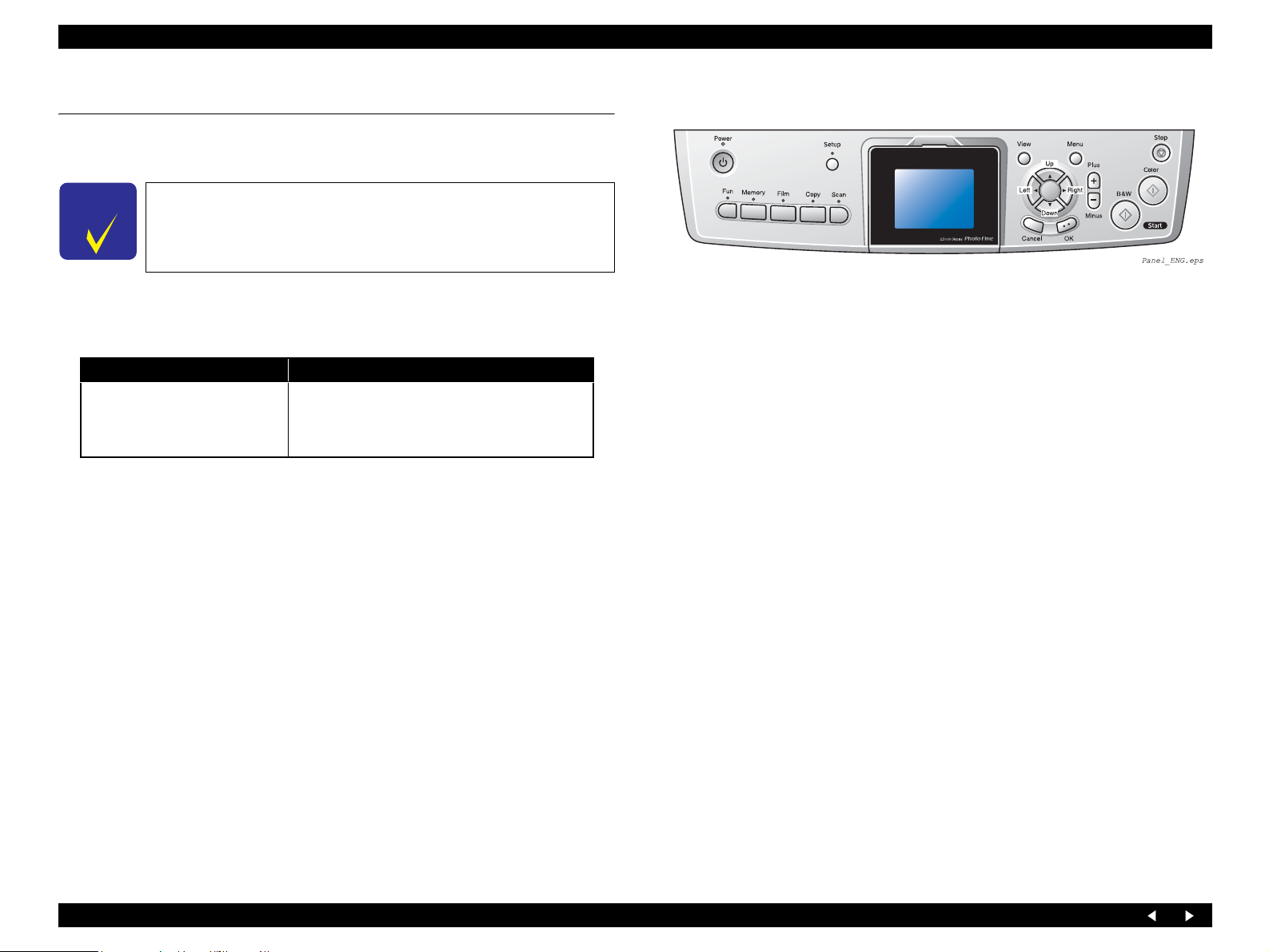
1.3 Special Operations
With Stylus Photo RX700, the special operation modes described below are available
by turning the power on with the specified buttons held down.
C H E C K
P O I N T
The functions described below, intended for use by service
personnel, must not be opened to users.
1.3.1 Operation for Forced Power Off
Table 1-12. Operation for Forced Power Off
Switches Function
Power + Stop
(Press Power SW first, and press
both switches for more than seven
seconds)
Turning the power off forcibly (processing
equivalent to power down)
Figure 1-3. Operation Panel
Product Description Special Operations 16
Page 17

OPERATING PRINCIPLES
CHAPTER
2
Page 18

EPSON Stylus Photo RX700 Revision A
2.1 Overview
PF Encoder Encoder Scale
This Chapter describes the operating principles of the mechanism and electric circuits
of Stylus Photo RX700.
APG Assy
2.1.1 Mechanical Components
The printer of Stylus Photo RX700 consists of the following major mechanisms:
Printhead (p.21)
Carriage Mechanism (p.22)
APG Mechanism (p.23)
Paper Feed Mechanism (p.26)
CD-R Mechanism (p.28)
Paper Loading Mechanism (p.30)
Ink Supply System (p.36)
Pressure Pump Mechanism (p.38)
Ink System (p.40)
In addition to the mechanisms mentioned above, the following mechanisms and circuit
boards constitute Stylus Photo RX700:
Scanner Unit (p.41)
Main Board (p.44)
Panel Board (p.47)
Power Supply Board (p.48)
Paper Eject Roller
E/J Assy
CR Assy
Printhead
PF Motor
Encoder Scale
Rear Paper
Guide Assy
CR Encoder
PE Sensor
Ink System Assy
ASF Rear Assy
ASF Motor
CR Motor
CR Guide Shaft
CR Belt
Figure 2-1. Schematic Printer Mechanism
Operating Principles for "ECOS" Overview 18
Page 19
EPSON Stylus Photo RX700 Revision A
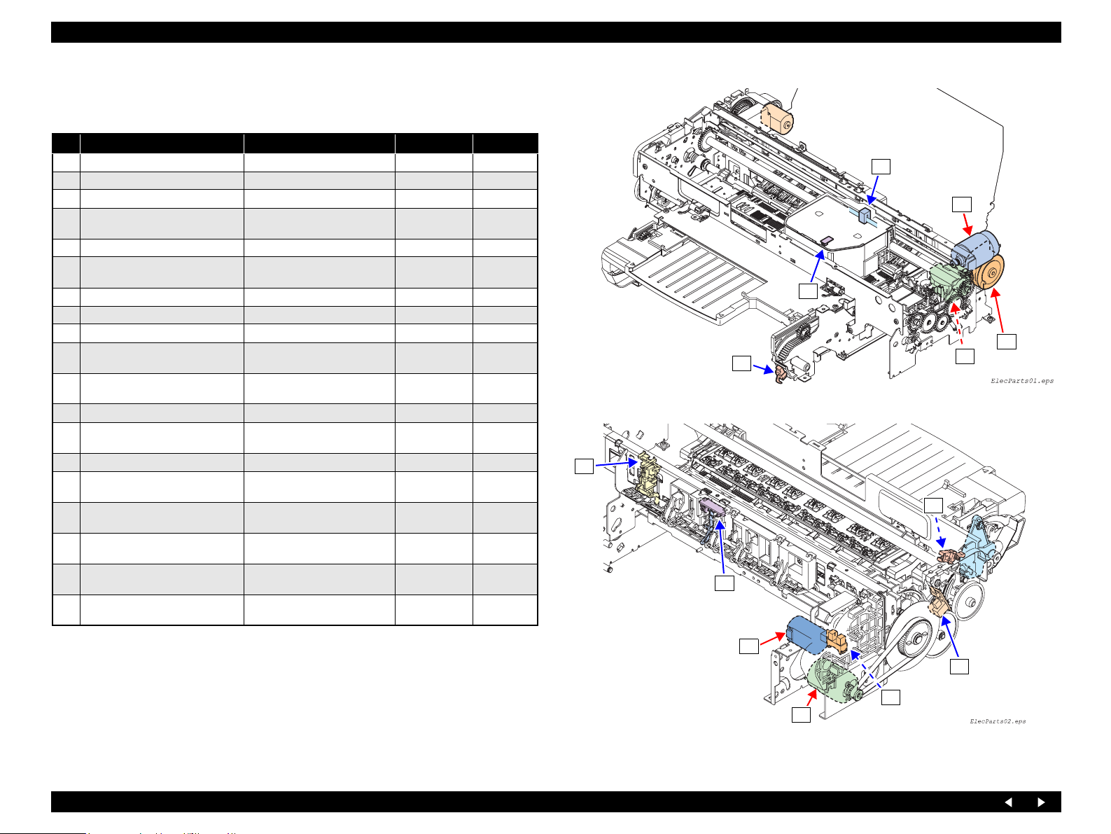
2.1.2 Motors and Sensors
Printer
No. Name Type Voltage Fig.No
A CR Motor DC motor
B APG Motor DC motor
C PF Motor DC motor
D ASF Motor
E Ink Supply System Pressure Motor DC motor (2-core, white)
F Pump Motor
1 PTS Detector (CR Encoder) Linear encoder
2 Ink Cartridge Detector (CSIC) CSIC
Paper Width Detector (PW
3
Detector)
4 APG Detector 1 (Position)
5 PF Encoder Linear encoder
6 PE Detector
7 Cover Tray Detector (2-core, yellow)
8 CD-R Sensor 1 (for Guide)
9 CD-R Sensor 2 (for Tray)
I/C Cover Opening/Closing
10
Switch
Ink Supply System Pressure
11
Sensor
Ink Supply System Pressure Assy
12
Detector
4-phase 48-pole PM type
stepping motor
4-phase 48-pole PM type
stepping motor
Reflective photo interrupter
Transmissive-type photo-
interrupter
Transmissive-type photointerrupter
Mechanical contact (2-core,
black)
Mechanical contact (2-core,
blue)
Mechanical contacts x2
Transmissive-type photo-
interrupter
Mechanical contact
42VDC±5% Figure 2-2
42VDC±5% Figure 2-3
42VDC±5% Figure 2-3
42VDC±5% Figure 2-2
3.3VDC±5% Figure 2-4
42VDC±5% Figure 2-2
3.3VDC±5% Figure 2-2
3.3VDC±5% Figure 2-2
3.3VDC±5% Figure 2-3
3.3VDC±5% Figure 2-3
3.3VDC±5% Figure 2-3
3.3VDC±5% Figure 2-2
3.3VDC±5% Figure 2-3
3.3VDC±5% Figure 2-3
3.3VDC±5% Figure 2-4
3.3VDC±5% Figure 2-4
3.3VDC±5% Figure 2-4
1
A
3
D
7
F
Figure 2-2. Motors and Sensors (Front Side of Mechanism)
6
9
8
B
(Continued to next page)
5
4
C
Figure 2-3. Motors and Sensors (Rear Side of Mechanism)
Operating Principles Overview 19
Page 20
EPSON Stylus Photo RX700 Revision A
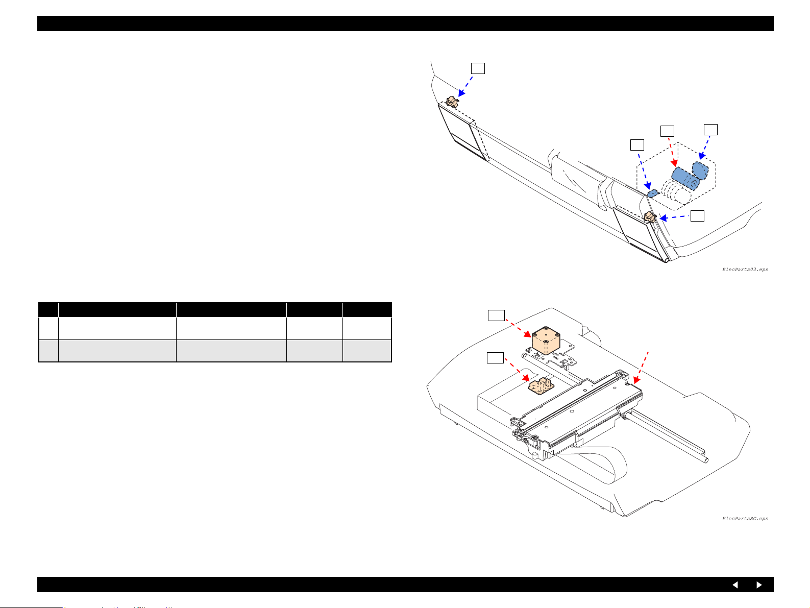
10
Scanner Unit
No. Name Type Voltage Fig.No
Scanner CR Motor
S1
Scanner Home Detector
S2
4-phase 200-pole HB stepping
motor
Transmissive‑type photointerrupter
42VDC ±5% Figure 2-5
3.3VDC±5% Figure 2-5
E
12
10
Figure 2-4. Motors and Sensors (Printer Housing)
S1
Carriage Unit Assy
S2
11
Figure 2-5. Motors and Sensors (Scanner Unit)
Operating Principles Overview 20
Page 21
EPSON Stylus Photo RX700 Revision A
2.2 Mechanism Operating Principles
This section describes the operating principles of the mechanism of Stylus Photo
RX700.
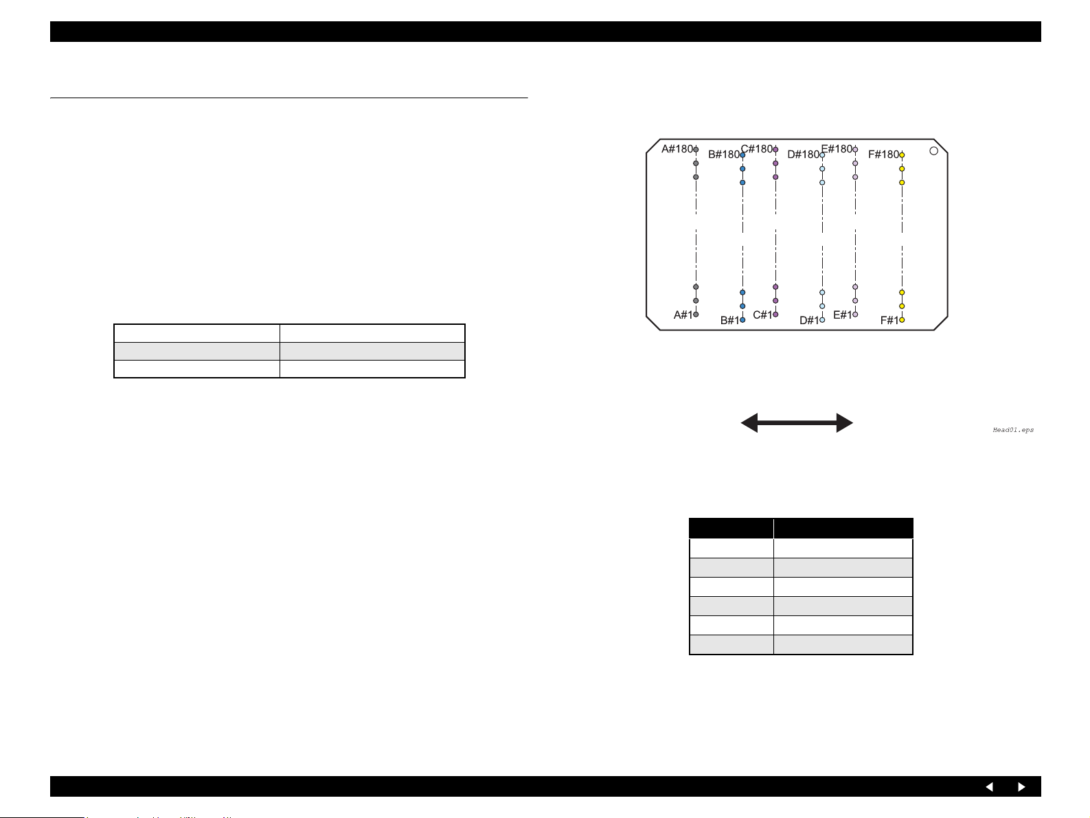
2.2.1 Printhead
The printhead of Stylus Photo RX700 is equipped with six rows of nozzles for six
colors. The head drivers consist of the driver on the head (nozzle selector) and the
driver on the circuit board (drive voltage waveform generating circuit).
Printing method: On-demand ink-jet (F-Mach head)
Nozzles
Colors Bk, C, M, Lc, Lm, Y (6 colors)
Ink change system None
The number of nozzles 180 nozzles in each color
Print direction
Text: Bidirectional shortest distance printing, Unidirectional
printing
Graphics: Bidirectional shortest distance printing, Unidirectional
printing
Row A
Row C
Row B
Carriage Moving Direction
Row D
Figure 2-6. Nozzle Arrangement
Nozzle Row Ink Color
ABlack
B Cyan
CMagenta
D Light Cyan
E Light Magenta
F Yellow
Row E
Row F
Operating Principles Mechanism Operating Principles 21
Page 22
EPSON Stylus Photo RX700 Revision A
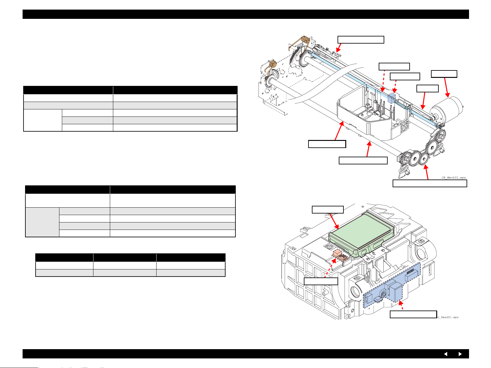
2.2.2 Carriage Mechanism
The Carriage Mechanism consists of the CR Motor, CR Belt, Driven Pulley Assy, CR
Guide Shafts (x2), Carriage Assy, CR Scale Mounting Plate Assy, Parallelism Adjust
Bushes (x4), APG Assy, etc.
2.2.2.1 CR Motor Specifications
Item Specifications
Type DC brush motor (Mabuchi Motor RS445PB-15205B)
Voltage 42 V (DC voltage) ± 5% (voltage applied to the driver)
Armature resistance 23.6Ω ± 15%
Characteristics
2.2.2.2 PW Sensor
Function
Detection of the top, bottom, right and left edges of a cut sheet
Detection of the center of CD-R
Detector specifications
Detection method
Electrical
characteristics
Inductance 17.5mH ± 25%
Rotor inertia 20.8 gcm
Item Specifications
Photo-electric conversion system (reflection type) (SHARP
GP2S700HCP)
Open-collector Collector withstand voltage 35 V or below
Sink current 0.2 mA or below
Drive voltage 1 3.3 V ± 5%
Drive voltage 2 3.3 V ± 5%
2
Driven Pulley Assy
Linear Scale
Carriage Assy
CR Guide Shaft (x2)
Figure 2-7. Carriage Mechanism
Printhead
CR Encoder
CR Scale Mounting Plate Assy
CR Motor
CR Belt
Switch mode
Detected Condition Switch Mode Detector Output
There is paper Open L ow voltage
There is no paper Closed High voltage
PW Sensor
Note : The leading signal is A/D-converted in 8 bits.
CR Encoder Board
Figure 2-8. Bottom of Carriage Assy
Operating Principles Mechanism Operating Principles 22
Page 23
EPSON Stylus Photo RX700 Revision A
2.2.3 APG Mechanism
2.2.3.1 APG Motor Specifications
Item Specifications
Type DC brush motor
Voltage 42V (DC voltage) ± 5% (voltage applied to the driver)
Armature resistance 64.7Ω ± 15%
Characteristics
Drive system PWM system, constant-current chopping system
PG Adjustment Direction Current
PG-
→ PG release: Larger PG
PG- ← PG release: Smaller PG
Drive system
PWM driving
Current
chopping
Inductance 33.6 mH ± 25%
Rotor inertia 3.97gcm
The motor is turned ON during the time determined by calculation in the specified PWM
fundamental period PWMcrc, and turned OFF during the rest of the period. The time
resolution of the PWM is 41.7 nsec, which is taken as one count. The motor is driven in
Slow Decay mode and stopped by a short brake. (Duty = 0)
The slow-decay mode (chopping OFF time of 50 µsec.) is always used during current
chopping for current control. The slow-decay mode is such that the blanking time is 6
2
Direction of Motor Rotation (as
viewed from the output side)
→ OUT_B CW
OUT_A
OUT_A ← OUT_B CCW
µsec. and both the transistors on the sink side are turned ON during chopping OFF in
PWM driving mode. (Synchronous rectification is enabled in the active mode.) The upper
limit current value is
± 0.5 A ± 8%.
APG Assy
APG Motor
CR Guide Shaft (Main)
APG Sensor
Release Assy
Upper Paper Guide
CR Guide Shaft (Front)
Carriage Assy
CR Scale Mounting Plate Assy
Figure 2-9. APG Mechanism
2.2.3.2 APG Sensor
Function: Detection of the PG position
Right Side
PG Right Cam
Spur Gear 25.6 (x2)
PG Right Cam
Detector specifications
Item Specifications
Detection method Photo-electric conversion system (transmissive-type photo-interrupter)
Electrical characteristics Voltage 3.3V ± 5%
Detected Condition Detector Output Remarks
Each PG position area
Between PG positions
Operating Principles Mechanism Operating Principles 23
H Light intercepted
L Light transmitted
Spur Gear 20.8
Figure 2-10. Gear Train of CR Scale Mounting Plate Assy
Page 24
EPSON Stylus Photo RX700 Revision A
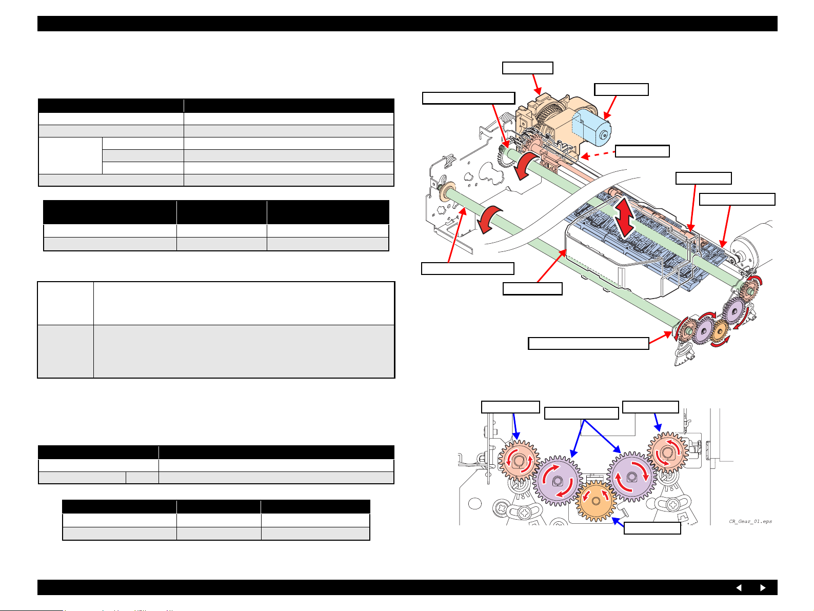
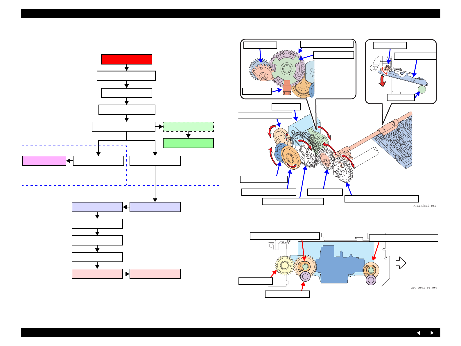
2.2.3.3 APG Driving Transmission
Shown below is the transmission path of driving force from the APG Motor.
APG Assy
APG Motor
Composite Gear 8, 22.986
Release Gear
Composite Gear 30, 35.2,
PG Sensor Flag
Release Assy
Upper Paper Guide
Release Assy
Release Assy
During CW rotation, the Upper
Paper Guides are pushed down
to set them to the PG++ state.
Carriage Assy
The carriage moves up
and down by rotation
of the right and left PG
Cams.
Composite Gear 11, 22
Composite Gear 10.8, 26
Composite Gear 30, 35.2, 39.6
Release Gear
Spur Gear 25.6
Spur Gear 20.8
Spur Gear 25.6
PG Right Cam
Spur Gear 22.4
PG Left CamPG Right Cam
PG Front Left Cam
PG Sensor Flag
APG Sensor
On the CR Guide
Shaft (Main)
On the CR Guide
Shaft (Front)
APG Sensor
APG Motor
Composite Gear 8, 22.986
Composite Gear 11, 22
Composite Gear 10.8, 26
Composite Gear 30, 35.2, 39.6
Figure 2-11. Transmission of Driving Force from the APG Motor
PG Right Cam (CR Guide Shaft)
Spur Gear 22.4
PF Roller
Spur Gear 22.4
PG Right Cam (CR Guide Shaft)
PG Right Cam (CR Guide Shaft)
Front
PG Cam Bush (x2)
Flowchart 2-1. Transmission Path of Driving Force from the APG Motor
Because of the eccentricity of PG Right Cams
(x2), the carriage moves up and down.
Figure 2-12. Outline of CR Up and Down Operation
Operating Principles Mechanism Operating Principles 24
Page 25
EPSON Stylus Photo RX700 Revision A
s
2.2.3.4 Driving Specifications
Basic control operation
The PG setting in several stages for the Carriage is achieved by moving the CR
Guide Shafts up and down with the DC motor while monitoring with the position
sensors. The control of the DC motor is referred to as Auto PG control (APG
control). The basic operation to realize this control is as follows:
<Setting Control>
To move the CR Guide Shafts from the current PG position to a designated PG position, the DC
1
motor is driven by energization (Duty) according to the time setting, slowed down by receiving
the signal from the sensor 1, and stopped within the PG setting range.
<Reset Control>
By unidirectional energization according to the time setting, the DC motor is driven and stopped
2
at the stopper position. Then PG positions are counted until the Position 1 is reached. Arrival at
the Position 1 is determined when the number of the PG positions is equal to the theoretical value.
APG control operation mode
There are five PG positions, which are determined by a continuous cam profile. Switching
1
between these positions is permitted in sequence: posi.1
The sensor 1 outputs the H and L signals when each PG position area and each area between
2
adjacent positions are detected, respectively. (See the table below for operation modes.)
To set and recognize each PG position area, rotate the motor in the posi.5 direction of the sensor
1 until it is stopped by the stopper. Then rotate the motor back in the posi.1 direction. The five
position areas are recognized in sequence; posi.5
this point, posi.1 is established as the first position. This position flag continues this recognition
3
of the positions until setting of the positions is newly made by a higher sequence.
Each PG position area is set when it is recognized that the signal from the sensor 1 changes as L
→ H (or H → L).
⇔ posi.2 ⇔ posi.3 ⇔ posi.4 ⇔ posi.5
⇒ posi.4 ⇒ posi.3 ⇒ posi.2 ⇒ posi.1. At
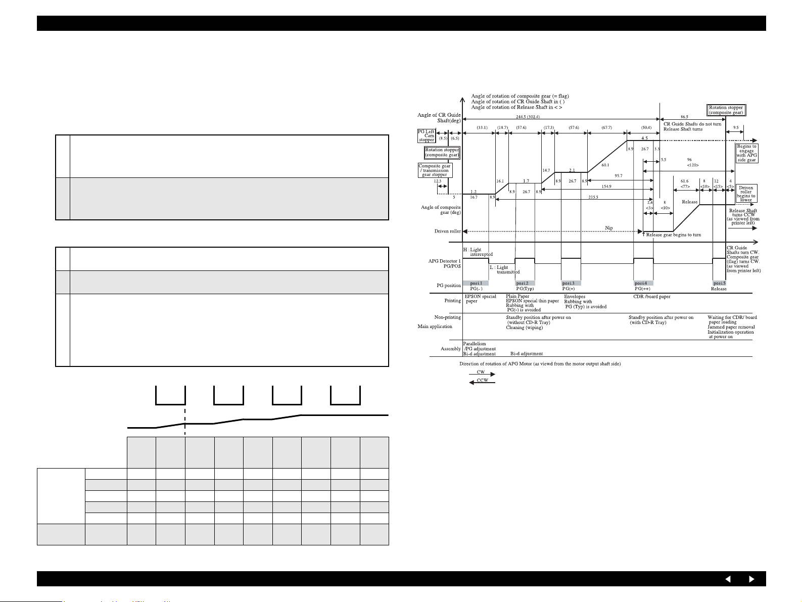
Figure 2-13 below shows the relationship between the PG positions and the outputs of
the sensor 1 as well as major applications of the PG positions.
Sensor 1 output
PG schematic diagram
End position
Starting position
Setting
control
Reset control
Position not
High
Low
posi.1
PG–
posi.1 {
posi.2 { {
posi.3 {{
posi.4 { {
posi.5 {
identified
{ {
←Reference edge
posi.1-2 posi.2
PG typ
posi.2-3 posi.3
{ mark shows each pair of position
where basic control takes place.
posi.3-4 posi.4
PG+
posi.4-5 posi.5
PG++
Release
Reduction gear ratio between PG motor ~ composite gear (flag) = 1/91.93
Reduction gear ratio between PG motor ~ CR Guide Shaft = 1/71.04
Reduction gear ratio between PG motor ~ Release Shaft = 1/73.54
• CR Guide Shaft turning angle = Composite gear turning angle
* In any PG changing area, the CR Guide Shafts move up and down (the cam gear rotates). Therefore, the
above conversion equation cannot be used.
• Release Shaft turning angle = Composite gear turning angle
× (44/34)
×(30/24)
Figure 2-13. PG Positions and Sensor Outputs, and Major Applications
Operating Principles Mechanism Operating Principles 25
Page 26
EPSON Stylus Photo RX700 Revision A
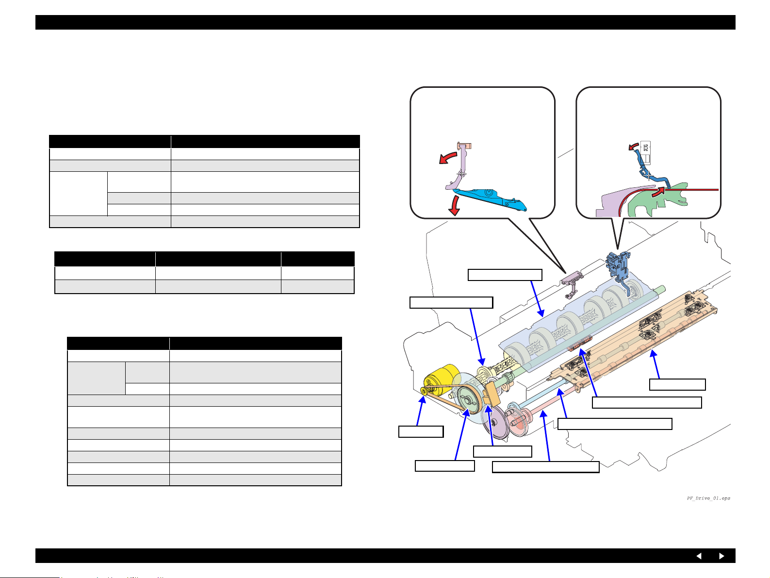
2.2.4 Paper Feed Mechanism
The paper feed mechanism, consisting primarily of the PF Motor, PF Roller Assy and
Paper Eject Rollers (x2), transports the paper from the paper loading mechanism and
ejects it to the front.
2.2.4.1 PF Motor Specifications
Item Specifications
Type DC brush motor
Voltage 42 V (DC voltage) ± 5% (voltage applied to the driver)
Armature
Characteristics
Drive system PWM system, constant-current chopping sy stem
resistance
Inductance 16.7mH (1KHz)
Inertia 12.4 gcm
26.4Ω ± 10%
2
Paper feed direction
Paper Feed Direction Direction of Motor Rotation Current
Normal CW PF-A
Reverse CCW PF-B → PF-A
→ PF-B
2.2.4.2 PF Encoder
Detector specifications
Item Specifications
Detection method (SHARP GP1A038CKL)
Electrical
characteristics
Output waveform Phase A and phase B 2-channel digital output (TTL)
Output level
Resolution 1/180 pulse/inch
Signal detecting element Photo interrupter
Duty ratio 50% ± 20%
Output phase difference 90° ± 54°
Frequency response 20kHz
Supply
voltage
Current 16 mA (40 mA MAX) 120Ω
3.3 VDC ± 5%
“H” 2.4 V DC min.
“L ” 0. 4 V DC max
CD-R Sensor 1
Detects the position (PG++) of the
Upper Paper Guides
When the Upper Paper
Guides have been
located at the PG++
position, the actuator
moves and the sensor
detects the position.
Upper Paper Guides
Idle Roller Shaft Assy
PF Motor
PF Encoder
PF Roller Assy
Front Paper Eject Roller Shaft
PE Sensor
Detects the presence of paper.
EJ Frame Assy
PF Roller Holder Support Assy
Rear Paper Eject Roller Shaft
Figure 2-14. Components of Paper Feed Mechanism
Operating Principles Mechanism Operating Principles 26
Page 27
EPSON Stylus Photo RX700 Revision A
2.2.4.3 PE Detector
Function : • Detection for paper positioning control
• Detection of the paper tail end
Detector specifications
Item Specifications
Detection method Photo-electric conversion system (transmissive type) SHARP GP1S94
Open-collector Collector withstand voltage 30 V or below
Electrical
characteristics
Sink current 0.3 mA or below
Drive voltage 1 3.3 V ± 5%
Drive voltage 2 3.3 V ± 5%
Detected Condition Switch Mode Detector Output
There is no paper
There is paper
Closed 2.4 V or above
Open 0.4 V or below
Recognition of the change of the PE signals:
The recognition during driving of the ASF Motor is such that the signal is read and
judged immediately (within 100 µs) after phase switching.
NOTE: Once “no paper” has been detected during driving of the PF Motor,
paper detecting operation does not take place during paper feeding by
the PF Motor until paper ejecting operation is completed.
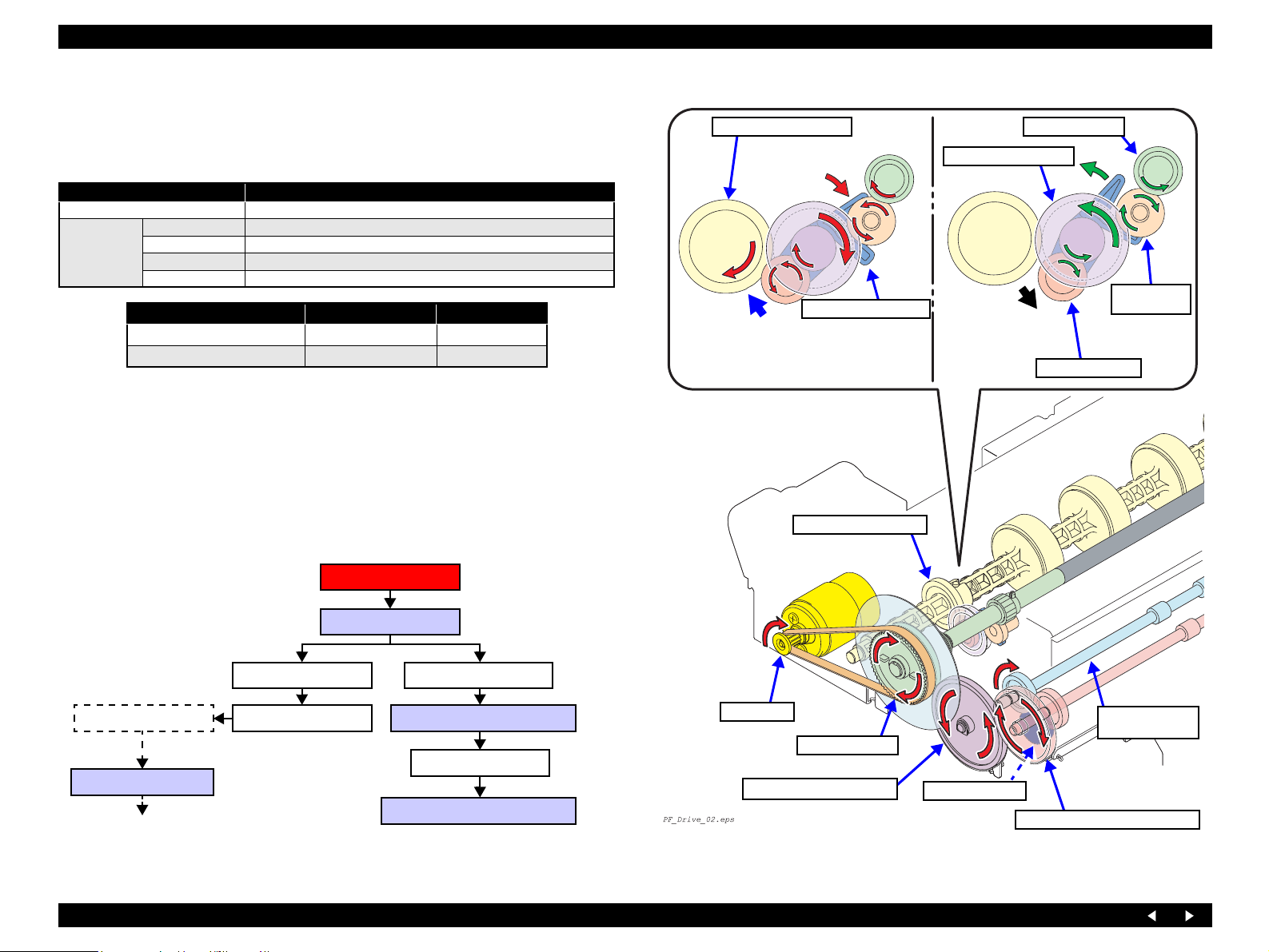
Idle Roller Shaft Assy
(Transports the front-
loaded paper)
Engaged
During CW rotation, the Epicyclic Gear
Holder turns clockwise, and the Epicyclic
Gear and Idle Roller Shaft Assy are engaged
to transmit driving force.
Epicyclic Gear Holder
Idle Roller Shaft Assy
Composite Gear 12, 10
Disengaged
PF Roller Assy
Transmission
Gear 12
Epicyclic Gear 12
2.2.4.4 Transmission Path of Driving Force for Paper Feed
PF Motor
PF Roller Assy
Transmission Gear 12 EJ Transmission Gear B
Epicyclic Gear 12
No transmission during
CCW rotation
Idle Roller Shaft Assy
See Flowchart 2-1.(p.32)
Composite Gear 12, 10 Front Paper Eject Roller Shaft
Spur Gear 15.5
Rear Paper Eject Roller Shaft
Flowchart 2-1. Transmission Path of Driving Force from the PF Motor
PF Motor
PF Roller Assy
EJ Transmission Gear B
Spur Gear 15.5
Front Paper Eject Roller Shaft
Figure 2-15. Transmission Path of Driving Force from the PF Motor
Rear Paper Eject
Roller Shaft
Operating Principles Mechanism Operating Principles 27
Page 28
EPSON Stylus Photo RX700 Revision A
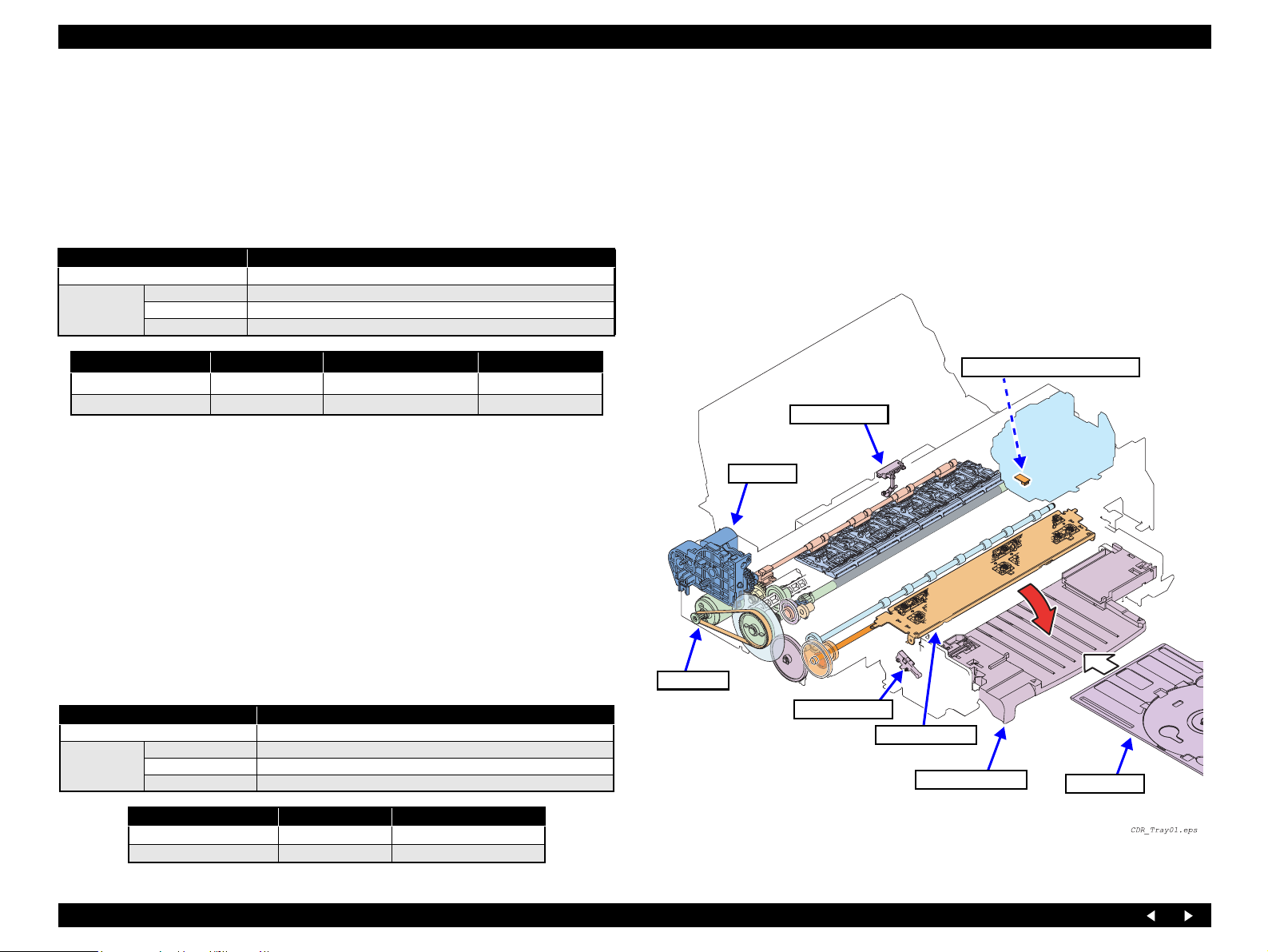
2.2.5 CD-R Mechanism
Stylus Photo RX700 supports printing on CD-R/DVDs. It executes printing on the
media placed on the CD-R tray, which is supplied as a standard accessory.
2.2.5.1 CD-R Sensor 1 (for Guide)
Function: Detection of CD-R Guide position
Detector specifications
Item Specifications
Detection method Mechanical contact detector leaf by MIK Electronic: 2020393(R-E04)
Electrical
characteristics
Detected Condition Switch Mode Applicable Printing Mode CD-R Guide Signal
CD-R Guide retracted
CD-R Guide used
Note 1: Even when the CD-R Guide position changes as “retracted → used”, the PG setting
2: Even when the CD-R Guide position has been changed as “retracted
3: Before printing and at other times, the CD-R Guide position is judged and the
Drive voltage 3.3 V ± 5%
Rated current 0.6 ~ 1 mA
Contact resistance 50mΩ
Open ASF mode H
Closed CDR mode L
(release) does not take place if there is paper.
→ used”, the CD-
R tray cannot be set until the PG setting (release) is completed. The user is alerted by a
panel display.
applicable printing mode is set
During printing, the CD-R Guide position is checked. If “CD-R Guide used” is detected
in the ASF mode, printing is discontinued. Then printing is resumed when “CDR Guide
retracted” is detected.
CD-R Tray Signal
Before printing in the CDR mode and other times, the CD-R Guide position is
judged.
CD-R Tray not installed: CD-R Guide error is displayed
CD-R Tray installed: If timer-controlled suction and I/C replacement are
necessary, the CD-R Tray is ejected and the user is
alerted during suction operation. If suction
operation is unnecessary, operation for printing on
the CD-R is carried out.
PW Sensor (on the Carriage)
CD-R Sensor 1
APG Assy
2.2.5.2 CD-R Sensor 2 (for Tray)
Function: Detection of CD-R Tray position
Detector specifications
Item Specifications
Detection method Mechanical contact detector by MIK Electronic: MPU10420MLB0
Electrical
characteristics
Operating Principles Mechanism Operating Principles 28
Drive voltage 3.3 V ± 5%
Rated current 0.6 ~ 1 mA
Contact resistance 50mΩ
Detected Condition Switch Mode CD-R Tray Signal
CD-R Tray not installed Closed L
CD-R Tray installed Open H
PF Motor
CD-R Sensor 2
EJ Frame Assy
CD-R Guide Assy
CD-R Tray
Figure 2-16. Components of the CD-R Mechanism
Page 29
EPSON Stylus Photo RX700 Revision A
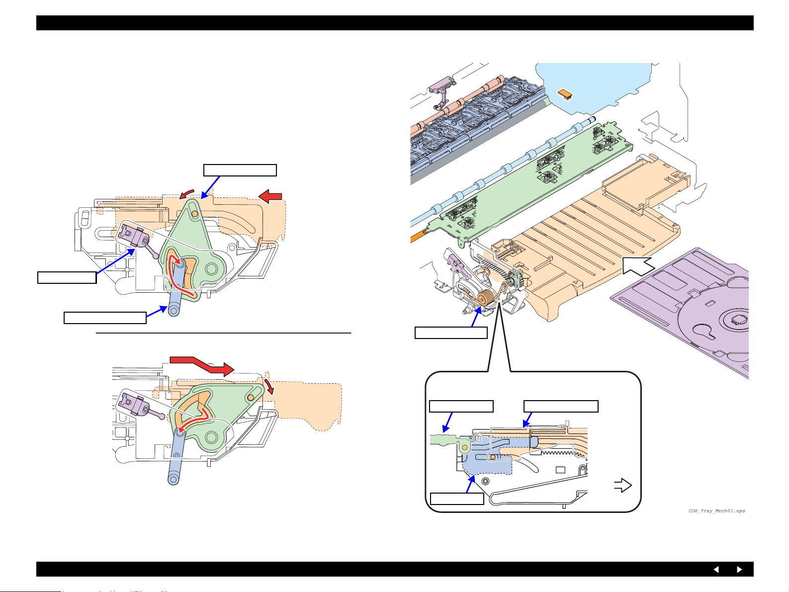
2.2.5.3 CD-R Mechanism Explanation
The CD-R Mechanism is as follows: When the CD-R Guide Assy is drawn out toward
the front, its position is detected by the CD-R Sensor 2 (Front). Then the APG Assy
widens the platen gap to the PG++ position so that the CD-R Tray can be loaded.
The CD-R Mechanism is driven as follows: The CD-R Tray inserted by hand is loaded
and ejected by the driving force transmitted from the PF Motor to the PF Roller and
Paper Eject Rollers (x2). (See Figure 2-15)
CD-R Guide is retracted
CD-R Sensor 2
CD-R Link Lever
CD-R Guide is open
CD-R Right Cam
The CD-R Link Lever locks the CD-R Guide
Assy with the CD-R Right Cam in the position
shown, which is detected by the sensor.
Torsion spring (x2)
Slides to the front by
the force of the right
and left springs
The E/J Frame and the CD-R Guide operate connected
with each other by the right and left EJ Links.
CD-R Guide AssyEJ Frame Assy
To draw out the CD-R Guide, push the CD-R
Guide Assy inward slightly. Then the CD-R
Guide Assy is unlocked from the CD-R Link
Lever and locked in the position shown.
Left EJ Link
Front
Figure 2-17. Detection of CD-R Guide Position
Figure 2-18. CD-R Mechanism
Operating Principles Mechanism Operating Principles 29
Page 30
EPSON Stylus Photo RX700 Revision A
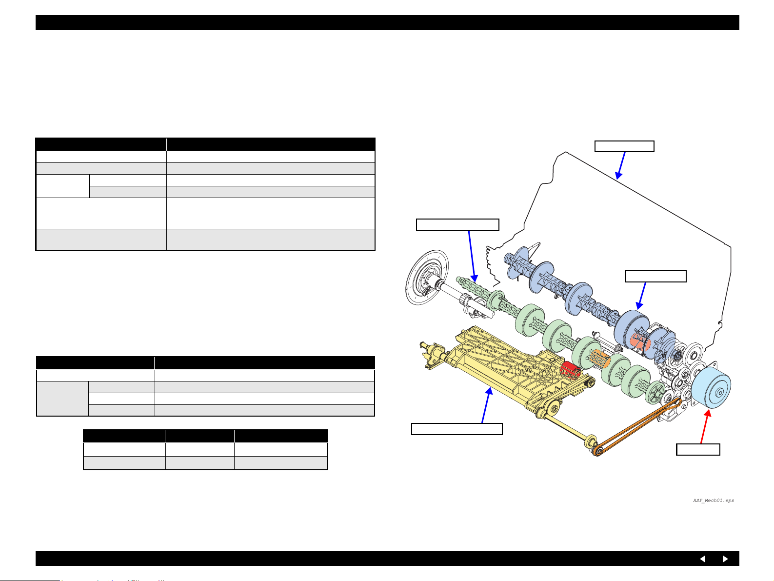
2.2.6 Paper Loading Mechanism
Stylus Photo RX700 is provided with two-way paper loading system, permitting paper
loading from the front and rear. The paper loading system consists of two paper
loading mechanisms and the ASF Drive Assy.
2.2.6.1 ASF Motor
Item Specifications
Type 2-phase 48-pole PM type stepping motor
Voltage 42 V (DC voltage) ± 5% (voltage applied to the driver)
Characteristics
Drive system
Driving resolution
Winding resistance 7.0Ω ± 10%(25°C/phase)
Inductance 10.3mH ± 20%(1kHz, 1Vrms, 25°C)
Bipolar driving
2-2 phase, 1-2 phase, W1-2 phase, 2W1-2 phase, 4W1-2 phase
constant-current driving
1/126.6 inch (0.201 mm/pulse) (2-2 phase excitation)
(Resolution on the Rear Paper Feed Roller)
2.2.6.2 Cover Tray Detector
Function: Detection of Cover Tray opening/closing
(appropriate one of the following operations is performed)
Cover Tray is closed: Warning is displayed on the LCD or PC monitor.
Cover Tray is open: Printing operation is continued.
Detector specifications
Item Specifications
Detection method Mechanical contact detector by MIK Electronic: MPU10980MNB0
Electrical
characteristics
Drive voltage 3.3 V ± 5%
Rated current 0.6 ~ 1 mA
Contact resistance 500mΩ
ASF Rear Assy
Idle Roller Shaft Assy
LD Roller Assy
Detected Condition Switch Mode Cover Tray Signal
Cover Tray is closed
Cover Tray is open
Closed L
Open H
ASF Pick Up Shaft Assy
ASF Motor
Figure 2-19. Components of Paper Loading Mechanism
Operating Principles Mechanism Operating Principles 30
Page 31

EPSON Stylus Photo RX700 Revision A
2.2.6.3 Transmission Path of Driving Force for the Paper Loading Mechanism
The ASF Motor switches the paper source between the two feeders by changing the
direction of rotation. This section describes the transmission path of driving force from
the ASF Motor and each paper loading mechanism.
CCW: Front paper loading
CW : Rear paper loading
ASF Motor
Composite Gear
27.5, 15.2
Composite Gear
27.5, 15.2
Composite Gear
17.5, 15.2
ASF Motor
Pick Up Gear
During CCW rotation of the motor, the rear spur
gear is engaged with Pick Up Cam, to move it
rearward so that ASF Pick Up Shaft Assy lowers.
Pick Up Roller
Spur Gear 12.8
Pick Up Cam
See Flowchart
2-1.(p.32)
ASF Gear
17.6
Spur Gear 11.2
FD Belt
FD Gear 9.6
Spur Gear 14.4
The belt runs only during
CCW rotation of motor.
Pick Up Roller
Transports paper
Composite Gear
17.5, 15.2
ASF Gear 17.6
Spur Gear 11.2
Spur Gear 10 Pick Up Gear
Pick Up Clutch
Pick Up Belt
Pick Up Retard Shaft
CW: Up (retracted)
CCW: Down (paper transport)
Spur Gear 12.8 (x2)
Moves the ASF Pick Up
Shaft Assy up and down
FD Belt
Flowchart 2-1. Transmission Path of Driving Force from the ASF Motor 1
FD Gear 9.6
Pick Up Clutch
Only during CCW rotation of the motor,
the Pick Up Clutch transmits driving
force to turn the Pick Up Roller.
Spur Gear 14.4
Spur Gear 10
During CCW , the PF Rear Clutch is
brought down toward the front to
disconnect the drive mechanism from
the ASF Rear Assy.
Figure 2-20. Transmission Path of Driving Force from the ASF Motor 1
Operating Principles Mechanism Operating Principles 31
Page 32

EPSON Stylus Photo RX700 Revision A
ASF Motor
Composite Gear
17.5, 15.2
See Flowchart
2-1.(p.31)
Composite Gear
14.7
Trigger Gear
48
PF Motor
See Flowchart
2-1.(p.27)
Idle Roller Shaft
Assy
Spur Gear 16
Ratchet Gear
LD Roller
Assy
Paper Reversing
Trigger
Paper Reversing
Clutch
PF Rear
Clutch
PF Rear
Trigger
Paper Reversing
Cam
Composite Gear
27.5, 15.2
Composite Gear
27.2, 15.2
Spur Gear 29.6
Flowchart 2-1. Transmission Path of Driving Force from the ASF Motor 2
Composite
Gear
Composite
Gear
27.5, 15.2
PF Roller Assy
Idle Roller Shaft Assy
Spur Gear 29.6
Composite Gear 14.7
Trigger Gear 48
Figure 2-21. Transmission Path of Driving Force from the ASF Motor 2
Paper location
Paper
Cam (Left)
By the effect of the cam at the left side of
the LD Roller Assy, the Paper Reversing
Lever Shaft moves back and forth.
Reversing
Lever Shaft
By the effect of the cam at the
right side of the LD Roller Assy,
the hopper moves back and forth.
Hopper
Cam (Right)
Figure 2-22. ASF Rear Assy Mechanism
Operating Principles Mechanism Operating Principles 32
Page 33

EPSON Stylus Photo RX700 Revision A
Outlined below is the operation of each paper loading mechanism.
Outline of the Rear Paper Loading Mechanism
ASF Motor (CW)
PF Rear Clutch: locked
Paper Reversing Clutch: unlocked
FD Belt rotation (CW)
Lifts up the ASF Pick Up Shaft Assy.
During CW rotation of the ASF Motor, the Pick Up Clutch
does not operate to turn the Retard Roller.
Transmits the driving force to the LD
Roller to load paper from rear.
Does not transmit the driving
force from the Idle Roller to the
Paper Reversing Roller.
Outline of the Front Paper Loading Mechanism
ASF Motor (CCW)
PF Rear Clutch: unlocked
Does not transmit the driving
force to the LD Roller.
During CW rotation, the PF Rear Clutch
is locked to transmit the driving force to
the ASF Rear Assy.
CW CCW
PF Rear Clutch
ASF Motor
CCW
Paper Reversing Clutch
During CCW rotation, the Paper Reversing
Clutch is locked to transmit the driving
force of the PF Motor to Paper Reversing
Shaft.
CCW 時、紙戻しクラッチのロックを解除
し、PF モータからの駆動力を紙戻しク
ラッチのギアに伝達する。
CW CCW
Idle Roller Shaft Assy
Paper Reversing Clutch: unlocked
Transmits the driving force
from the Idle Roller to the
Paper Reversing Shaft.
FD Belt rotation (CCW)
Paper Reversing Shaft
Idle Roller
Lower the ASF Pick Up Shaft Assy.
The Retard Roller turns to transport paper.
Paper Reversing Shaft
Shaft Assy
The cam of the Paper Reversing
Clutch, coming in contact with
the lever of the Paper Reversing
Shaft, operates the shaft.
Figure 2-23. Outline of the Trigger Mechanism
Operating Principles Mechanism Operating Principles 33
Page 34

EPSON Stylus Photo RX700 Revision A
2.2.7 Outline of Paper Path
Stylus Photo RX700 is provided with two paper paths for front paper loading and rear
paper loading. The paper paths consist of the respective paper loading mechanisms.
CD-R printing is also supported using the supplied CD-R Tray. This section outlines
the paper paths.
Paper Loading
Method
Rear paper loading
(See Figure 2-24)
Front paper loading
(See Figure 2-25)
CD-R loading
(See Figure 2-26)
Drive Rollers
Paper Loading Mechanism PF Mechanism
• Retard Roller
• Pick Up Roller
• (Set the CD-R Tray by hand)
•PF Roller
• Paper Eject Rollers (x2)
•PF Roller
• Paper Eject Rollers (x2)
• Idle Roller
•PF Roller
• Paper Eject Rollers (x2)
Retard Roller
PF Roller
Paper Eject Rollers
Figure 2-24. Path of Rear-loaded Paper
Operating Principles Mechanism Operating Principles 34
Page 35

EPSON Stylus Photo RX700 Revision A
PF Roller
Paper Eject Rollers
The CD-R Sensor 1
detects PG++ (presence/
absence of the tray), and
the PW Sensor on the
carriage detects the
center of the CD.
CD-R Sensor 2
CD-R Sensor 1
PG++ is set
When the CD-R Tray has
been opened (manually),
which is detected by the
CD-R Sensor 2, the platen
gap is set to PG++.
Idle Roller
The ASF Pick Up Shaft Assy lowers
and loads paper.
PF Roller
Pick Up Roller
Paper Eject Rollers
Figure 2-25. Path of Front-loaded Paper Figure 2-26. Path of CD-R
Operating Principles Mechanism Operating Principles 35
Page 36

EPSON Stylus Photo RX700 Revision A
2.2.8 Ink Supply System
The printer is of an off carriage type in which the ink cartridges are contained in the
right and left I/C Holder Assy.
By the Pressure Pump Assy, compressed air is sent through the Pressure Sensor Assy
to the Left Ink Duct Assy. From there, the air is supplied into the left ink cartridges
(x3) and through the Right Ink Duct Assy into the ink cartridges (x3) in the Right I/C
Holder.
The sent air presses the ink bag in each ink cartridge. The ink pushed out is supplied
through the Left/Right Ink Duct Assy → Ink Tube Assy → Valve Assy to the
Printhead.
2.2.8.1 I/C Cover Opening/Closing Switch
Function: Detect ion of I/C Cover opening/closing
(appropriate one of the following operations is performed)
I/C Cover is closed: Warning is displayed on the LCD or PC monitor.
I/C Cover is open: Printing operation is continued.
Detector specifications
Item Specifications
Detection method Mechanical contact detector by MIK Electronic: MPU10980MNB0
Electrical
characteristics
Drive voltage 3.3 V ± 5%
Rated current 0.6 ~ 1 mA
Contact resistance 500mΩ
Valve Assy (including Ink Tube Assy)
Printhead
I/C Holder Assy
Detected Condition Switch Mode I/C Cover Switch Signal
I/C Cover is closed
I/C Cover is open
Note : When the I/C Cover Switch has opened (signal has turned H) during printing,
“Cartridge cover open error” is displayed.
Closed L
Open H
Ink Cartridge
Pressure Pump
Pressure Sensor
Figure 2-27. Ink Path
Operating Principles Mechanism Operating Principles 36
Page 37

EPSON Stylus Photo RX700 Revision A
2.2.8.2 Self-closing Valve
The Valve Assy is equipped with the self-closing valve to prevent ink from flowing
back.
The self-closing valve works as a sub tank to compensate for a temporary shortage of
ink supply to the off carriage type head. When solid printing is performed with a
printhead of an off carriage type, there may be a case where an excessive volume of a
specific ink is consumed temporarily and dot missing can occur.
Use of this valve ensures a uniform print quality.
When ink in the Valve Assy is supplied to the Printhead, the pressure in the Ink Storage
Chamber drops, so that the Valve Lever is tilted by the Pressure Receiving Plate. When
the Valve Lever inclines, the ink passage from the Ink Tube to the Valve Assy opens,
so that ink is supplied to the Ink Storage Chamber.
When the Ink Storage Chamber is filled with ink, the Valve Lever tilted by the Pressure
Receiving Plate is raised, so that the Valve Lever closes the ink passage from the Ink
Tube Assy.
C H E C K
P O I N T
The capacity of each Ink Storage Chamber is equivalent to
printing of 36 pages of graphics.
Stylus Photo RX700 uses six colors, thus two chambers are left
out of use.
Filter Ink Storage Chamber Valve Lever
Pressure
Receiving
Plate
To Printhead
Valve Lever
Filter
LM
M
LC
BkC
No ink
No ink
Y
To Printhead
Figure 2-28. Self-closing Valve
Operating Principles Mechanism Operating Principles 37
Page 38

EPSON Stylus Photo RX700 Revision A
2.2.9 Pressure Pump Mechanism
2.2.9.1 Pressure Pump Motor
Item Specifications
Type DC brush motor
Voltage 42 V (DC voltage) ±5% (voltage applied to the driver)
Basic
characteristics
Drive system PWM system, constant-current chopping system
Operation Current
Pressure
Pressure release
Drive system
PWM driving
method
Current chopping
method
Armature resistance 64.7Ω ±15%
Inductance 37.6mH ±25%
Rotor inertia 3.97 gcm
OUT_A → OUT_B CW
OUT_A → OUT_B CCW
The PWM fundamental period resolution is 24 MHz (= 41.7 nsec), wh ich is taken as
one count. The output time is the ON time, while the remaining time is OFF time.
During the OFF time in PWM driving mode, the slow-decay mode is used with both
the transistors on the sink side turned ON (synchronous rectification is enabled in the
active mode). Unless specified, the motor is stopped by a short brake (duty=0).
The slow-decay mode (chopping OFF time of 50 µsec.) is always used during
current chopping for current control. The slow-decay mode is such that the blanking
time is 6
µsec. and both the transistors on the sink side are turned ON during
chopping OFF in PWM driving mode. (Synchronous rectification is enabled in the
active mode.) The upper limit current value is ± 0.63[A] ± 8%.
2
Direction of Motor Rotation
(as viewed from the output side)
Pressure Sensor
Pressure Pump Motor
Pressure Pump
Relief Valve
Pump HP Sensor
CW rotation
2.2.9.2 Pressure Sensor
Function: Detection of pressurization / pressure release
Detector specifications
Item Specifications
Detection method Photo-electric conversion system (transmissive-type photo-interrupter)
Model GP2S24C J000F (SHARP)
Voltage 3.3 V ± 5%
Detected Condition Detector Output Remarks
Pressurized
Pressure released
H Light transmitted
L Light intercepted
The valve is closed, so
that the compressed
air is supplied through
the I/C Holder to the
Printhead.
CCW rotation
When the gear turns
counterclockwise, the
lever pushes up the valve
to release the compressed
air from the chamber.
Figure 2-29. Pressure Pump Assy Mechanism
Operating Principles Mechanism Operating Principles 38
Page 39

EPSON Stylus Photo RX700 Revision A
2.2.9.3 Pump HP Sensor
Function : Detection of pump home position
Detector specifications
Item Specifications
Detection method Mechanical contact
Model D3C-2220(OMRON)
Voltage 3.3 V ± 5%
Detected Condition Detector Output Remarks
Pump in the HP area
Pump not in the HP area
HOPEN
L CLOSE
2.2.9.4 Driving Specifications
Basic operation
Pressurization
control
Pressure
Pump reset
Applies pressure to the inside of the ink supply passage. Drives the Pressure
Motor while checking the outputs of the Pressure Sensor and Pump HP
Sensor.
When the Pump HP Sensor turns L → H by the specified number of
additional pumping actions from the state where both sensors are H, the
motor is stopped by a short brake (Duty = 0) via stop control.
Initial pressurization raises the pressure up to above the threshold value of
the Pressure Sensor to reduce the required number of pumping actions.
If “Cover OPEN” is detected during the driving of the Pressure Motor, the
motor is stopped by a short brake (Duty = 0) immediately, without via the
stop control.
Releases the pressure in the ink supply passage to atmospheric pressure. If
the Pump HP Sensor is H, until it turns as H → L → H → L → H, while if it
is L, until it turns as L
continuously and stopped by a short brake (Duty = 0) via stop control.
(The motor is always stopped with the Pump HP Sensor signal at H to avoid
the condition where the bellows pump may creep if it is stopped in a shrunk
position.)
→ H → L → H → L → H, the motor is driven
Figure below shows the relationship between the pressure and the outputs of the Pump
HP Sensor (position detection: Sensor 1) and Pressure Sensor (Sensor 2) during the
operation of the Pressure Pump.
Pressure
The pressure is prevented from rising too
high by the regulator mechanism
Released to
atmospheric
pressure
Pump reset from H status
Pump reset from L status
Sensor 2 threshold
value
Additional
pumping
Pressure
applied
Sensor 2
(Pressure Sensor)
Sensor 1
(Pressure Pump
Assy)
Motor stopped
Direction of Pressure Motor rotation (as viewed from the output shaft)
Sencer_op_pr.eps
Relationship between Motor Operation and Sensor Outputs and Pressure
Figure 2-30.
Operating Principles Mechanism Operating Principles 39
Page 40

EPSON Stylus Photo RX700 Revision A
2.2.10 Ink System
2.2.10.1 Pump Motor
Item Specifications
Type 4-phase 48-pole PM type stepping motor
Voltage 42 V (DC voltage) ± 5% (voltage applied to the driver)
Basic
characteristics
Drive system
Driving conditions
Winding resistance 7.6Ω ± 10%(25°C/phase)
Inductance 13.4mH ± 20%(1kH 1Vrms)
Bipolar driving
2-2 phase, 1-2 phase, W1-2 phase, 2W1-2 phase, 4W1-2
phase constant-current driving
Angle of rotation of pump shaft per step of driving resolution
motor: 1.067 degrees/pulse (2-2 phase conversion)
2.2.10.2 Ink System Driving Conditions
With the Pump Motor as the drive source, the Ink System Assy is driven according to
the following conditions.
Drive settings (six modes)
Drive Mode Suction Speed Name
Constant-value drive -2
IS7
Constant-value drive
IS6
Low speed
IS5
Normal
IS4
High speed
IS3
Super-high speed 1
IS2
Super-high speed 2
IS1
Revolving Speed of Pump
Wheel (revolutions/s)
––
– –
0.8 TBD
2.2 TBD
3TBD
5 TBD
6TBD
Suction Flow
Rate (g/s)
During CW rotation, the
pin of the Cap Assy moves
to raise the Cap Assy and
the Carriage Lock Lever.
Pin
Cap Unit
Directions of
rotation of
gears during
CW rotation
Carriage Lock Lever
Operation settings
Direction of Pump Motor Rotation Operation of Pump Unit
Counterclockwise (CCW) rotation as
viewed from the rear side of the output
shaft of the motor
Clockwise (CW) rotation as view from the
rear side of the output shaft of the motor
Cap open (moving down)
Pump release
Wiper setting
CR unlocking
Cap closed (moving up)
Pump suction
Wiper reset
CR locking
Operating Principles Mechanism Operating Principles 40
Cap Assy
moves up to
push up the
lever and open
the tube cap.
Figure 2-31. Ink System
Page 41

EPSON Stylus Photo RX700 Revision A
2.2.11 Scanner Unit
The Scanner Unit consists primarily of the following components:
CCD Unit (Carriage Unit)
Consists of the CCD Board, mirrors and lens, lamp, and Inverter Board, and
moves on the CR Shaft.
HP Board
Informs the Main Board of HP detection of the CCD Unit, and conveys the signal
from the Main Board to the CR Motor.
CR Motor Unit
Moves the CCD Unit right and left via the Timing Belt.
TPU Assy
Works as the light source for scanning negative or positive film, incorporating an
inverter board and a lamp. Users can remove the TPU Assy by disconnecting the
Film Scan Connector from the Exterior Assembly.
TPU Assy
Figure 2-33. Transmission Path of Driving Force from the CR Motor
CCD Board
Lamp
ランプ
CCD
HP side
HP Board
CR Motor
Mirror (x5)
Lens
Figure 2-34. CCD Unit Internal Configuration
HP side
CCD Unit
Figure 2-32. Components of Scanner Unit
Figure 2-35. Image Path inside the CCD Unit
Operating Principles Mechanism Operating Principles 41
Page 42

EPSON Stylus Photo RX700 Revision A
2.2.11.1 CR Motor
Item Specifications
Type
Voltage 42 V ± 5%
Basic
characteristics
Step angle 1.8° /Full step
Drive system Bipolar constant-current driving
Maximum rating Power supply voltage 50 V, output current 800mA (per phase)
Winding resistance 6.3Ω ± 10%(25°C/phase)
Inductance 5.6mH ± 20%( 1k HzÅ A 1VrmsÅA25°C)
2-phase 200-pole HB stepping motor
(Shinano Kenshi: SHP-35D1010)
2.2.11.2 HP Sensor
Function: Detect ion of HP of the Carriage (CCD) Unit
Detector specifications
Item Specifications
Detection method
Light transmission type
(BRIGHT LED ELECTRONICS: BPI-3CI-05)
ø1Home position correction position
chart marking
Guaranteed scanning area
for reflective document
Carriage
moving
limit
Reflective document scanning area
Carriage
ScanArea01.eps
moving
limit
Figure 2-36. Reflective Document Scanning Area and Guaranteed Area
Operating Principles Mechanism Operating Principles 42
Page 43

EPSON Stylus Photo RX700 Revision A
2.3 Operating Principles of Electric Circuitry
2.3.1 Overview
The major circuit boards of Stylus Photo RX700 are as follows:
Main Board: C583MAIN
Power Supply Board: C583PSB/C583PSE
Panel Board: C583PNL
CCD Unit Board (Scanner):
2.3.2 Features
High-Speed SPC is realized without HUB, thanks to employment of USB 2.0
multi-end point.
An SOC incorporating the printer controller, scanner controller, PT controller
and CPU Super Macro is realized.
Only one CPU (NA85E 2S by NEC) controls the printer, scanner and PT
section.
Equipped with one 64-Mbit Flash ROM (with 16-bit bus width) and one 32-
Mbit Flash ROM (with 16-bit bus width).
Equipped with one 256-Mbit SDRAM (16-bit bus width) and one 128-Mbit
SDRAM (16-bit bus width) (two SDRAM in total) for ASIC local buses, and
one 256-Mbit SDRAM (16-bit bus width) for CPU bus.
Two motor driver ICs (RENESAS M63160J) are mounted, each of which
controls two DC motors and one stepping motor.
The band width is ensured by setting the operating frequency of the local
SDRAM of SOC at 96 MHz.
High-speed processing is ensured because all the processing from scanning to
binarization, Microweave, and image buffer generation is carried out inside
the SOC, without via the CPU bus.
Equipped with a color LCD (2.5-inch low-temperature poly-silicon TFT
liquid crystal) as a standard feature.
With the aid of the low-current LED, power consumption is suppressed by
executing the following actions at transition to the power save mode.
• Lowering the supply voltage for main power
• Cutting off the photo-electric current of the photo sensor
• Stopping the motor drive circuit
• Stopping the UDL clock inside the ASIC
• Entering the CPU core low consumption mode
• High η power supply circuit
• Stopping excitation of the printer motor
• Stopping the head drive circuit
• Turning off the CCD scanner power supply and stopping the excitation of the
scanner motor
• Turning off the preview monitor
Figure 2-37. Main Board
Figure 2-38. Power Supply Board
Operating Principles Operating Principles of Electric Circuitry 43
Page 44

EPSON Stylus Photo RX700 Revision A
2.3.3 Main Board
2.3.3.1 Outline of the Main Board
C583Main consists primarily of the three following sections.
Common section and printer section
Logic circuits (ASIC incorporated in the CPU core, ASIC for cards, Flash
ROM x 2, and SDRAM x 3)
Motor control and drive circuits (PF, CR, APG, Pressurization, ASF, Pump)
Head control and drive circuit
Interface circuit (USB 2.0, USB 1.1 Host)
LED circuit
Sensor circuits (PE, PW, APG, CDR 1 and 2, Stacker, Ink cartridges door, Ink
supply system pressure / pressurization)
RTC circuit
Regulator circuit
Overvoltage protection circuit
Color LCD interface
Panel interface
Card ASIC section
Logic circuit (ASIC)
Card power supply control circuit
Scanner section
Scanner interface circuit
Motor control and drive circuit (Scanner)
Scanner HP detection interface circuit
TPU interface circuit
2.3.3.2 Environmental Conditions
Operating temperature: 0 ~ 70°C inside the case
Operating humidity: 30 ~ 70%RH inside the case (no condensation)
2.3.3.3 Power Supply Specifications
Supply voltage for main power system: 42 V ±5%, 0.8 A (Max 2.5 A)
Supply voltage for scanner system: 12 V +5% -3.5%, 0.15 A
Supply voltage for logic system:
5 V ±5% (for 10 ms at startup +10%) 1.2 A
3.3 V ±5% (for 10 ms at startup +10%) 0.8 A (Max1.2 A)
1.5 V ±5% (for 10 ms at startup +10%) 0.8 A (Max1.2 A)
Output voltage control by the secondary side power switch:
If the power cable is unplugged when the power is ON, the voltages (3.3 V and 5
V) for the logic system are maintained for at least 350 msec. after the voltage for
the main power system has lowered below 32 V (Typ. 36.0 V, Max. 38.1 V).
Operating Principles Operating Principles of Electric Circuitry 44
Page 45

EPSON Stylus Photo RX700 Revision A
2.3.3.4 Main Board Circuit Configuration (Printer and Common Section)
IC Location Functions
SOC in CPU core IC12
FLASH ROM
(64Mbit)
FLASH ROM
(32Mbit)
SDRAM
(CPU bus)
SDRAM for
image processing
(256-Mbit chip
and 128-Mbit
chip)
Name: E01A56B*: by NEC (CPU: NA85E2S)
Built-in iLB RAM 32 Kbyte, Built-in dLB RAM 16 Kbyte
Built-in iCACHE 8 Kbyte, Built-in dCACHE 8 Kbyte
Operating frequency:
CPU core 192 MHz (SSCG)
NPB macro (UART, Timer C/D, prescaler) 48 MHz
User logic (Scanner / Printon) 48 MHz (SSCG)
User logic (Printer) 48 MHz
Local SDRAM 96 MHz (SSCG)
External bus clock 64 MHz (SSCG)
IC2
Name: MBM29PL64LM (Fujitsu) or the equivalent
Application: Program
Type: Flash memory chip powered by +3.3 V only, the data on which
can be erased totally or partially in sectors
Capacity: 64 Mbit(R4CD120)
Package: 48 Pin TSOP
Bus width: 16 bits
IC1
Name : MBM29PL32TM/BM (Fujitsu) or the equivalent
Application : Data / program
Type : Flash memory chip powered by +3.3 V only, the data on which
can be erased totally or partially in sectors
Capacity : 32Mbit
Package : 48 Pin TSOP
Bus width : 16 bits
IC11
NameK4S561632*(SAMSUNG) or the equivalent
Application : System memory
Type : 4 M Wor ds x1 6 bits x 4- ban k SDRAM
Bus width : 16 bits
Power supply : 3.3 V single power supply
Capacity : 256 Mbit(4Mx16bitx4bank)
Package : 54 pin TSOP
Operating frequency : 133 MHz (CL =2) or higher
IC13
Name: K4S561632*(SAMSUNG) or the equivalent (256 Mbits)
(256)
Application : Work memory for copy function
Bus width : 16 bits
IC14
Power supply : 3.3 V single power supply
(128)
Capacity: 256 Mbit (4 M x 16 bits x 4 banks) (256 Mbits)
Package : 54-pin TSOP
Operating frequency : 133 MHz (CL =2) or higher
K4S281632*(SAMSUNG) or the equivalent (128 Mbits)
128 Mbit (2 M x 16 bits x 4 banks) (128 Mbits)
IC Location Functions
RTC circuit IC3
CR/PF/Pump
motor drive
circuit
APG/Pressure/
ASF motor drive
circuit
DAC circuit for
motor driver Vref
Head drive
circuit
RTC9824: by Seiko Epson
Composite IC for reset function, RTC and EEPROM
IC7
Sleep mode is entered for power-saving.
Drive voltage : 42 V
Drive IC: M63160J (RENESAS)
CR motor
Drive system : DC motor control
Control method: PID feedback method
Current detection resistance: 0.36Ω
PF Motor
Drive system : DC motor control
Control method: PID feedback method
Current detection resistance: 0.36Ω
Pump motor
Excitation method: 2-2 phase / 1-2 phase / 4W1-2 phase
Drive system : Bipolar driving
Current detection resistance: 0.36Ω
IC8
Sleep mode is entered for power-saving.
Drive voltage : 42V
Drive IC: M63160J (RENESAS)
APG motor
Drive system : DC motor control
Control method: PID feedback method
Current detection resistance: 0.36Ω
Pressure motor
Drive system : DC motor control
Control method: PID feedback method
Current detection resistance: 0.36Ω
ASF Motor
Excitation method: 2-2 phase / 1-2 phase / W1-2 phase / 2W1-2 phase /
4W1-2 phase
Drive system : Bipolar driving
Current detection resistance: 0.36Ω
IC6
Name : M62384FP (Mitsubishi)
Application : Vref generation for motor driver ICs
IC5
Drive voltage : 42 V ±5%, VH is supplied to the head drive and control
circuit.
Head drive control through the control port of SOC.
Head drive control IC: E09A54RA (Sony)
±5%
±5%
±1% 1 Ω
±1% 1 Ω
±1% 1Ω
±1% 1 Ω
±1% 1 Ω
±1% 1Ω
Operating Principles Operating Principles of Electric Circuitry 45
Page 46

EPSON Stylus Photo RX700 Revision A
IC Location Functions
USB IF circuit
(USB 2.0)
USB IF circuit
(USB 1.1 Host)
Power supply
controller for
USB 1.1 Host
Energy save
circuit
DC-DC
converter circuit
Oscillation
circuit
(IC12)
(IC12)
IC4
IC700
Specification: Universal Serial Bus Specification Revision 2.0
Receive mode: High/Full speed mode
Receiving system: Bulk transfer / control transfer
Data reception capacity:
About 48.0 MB/s max. (bulk transfer in high speed mode)
About 1.15 MB/s max. (bulk transfer in full speed mode)
Control circuit: 2.0 USB controller SOC (E01A56B*)
Transceiver IC: PHY incorporated in SOC is used
Crystal oscillator: 48.000 MHz
Specification: Universal Serial Bus Specification Revision 1.1
Transmission mode: TPS2051A (by TI: IC 4) is mounted as the
overcurrent sensing circuit and power supply control circuit of the USB
port.
Data transmission capability: About 1.15 MB/s max. (bulk transfer in
full speed mode)
Control circuit: USB 1.1 Host controller in SOC (E01A56B*)
Crystal oscillator : 48.000 MHz
Name: TPS2051A(TI)
Package : 8-Pin PSOP
Function: Current limiting power control 1 CH
The control signal is active at high level.
When the PSC terminal is connected to GND via the 20 V Zener diode,
the Power Supply Unit enters the low-power mode.
Name: FA 7728 F (Fuji Electric Device Technology)
Application: 3.3 V power generation circuit for logic
1.5 V power generation circuit for logic
Input voltage range : 15 V~44 V
Capacity: 3.3 V 0.8 A (Max 1.2 A)
1.5 V 0.8 A (Max 1.2 A)
Model: Q22FA23800046
Element: Crystal oscillator
Frequ ency: 48.000 [MHz]
Remarks : 45-55% Duty
±500 ppm 45-55% duty
±500 ppm 45-55% duty
±500 ppm or less
2.3.3.5 Main Board Circuit Configuration (Card Section)
IC Location Functions
ASIC for card
section control
Compact Flash
I/F
Memory Stick
I/F
SmartMedia/xD
card I/F
SD card I/F
LED circuit
(Card section)
IC10
CN27
CN26
Name : E09A56B* (by NEC)
Manufacturing process: 0.35Éþ cell base IC CB9-VX
Package: 144 pin QFP
Supply voltage: 3.3 V single power supply
Operating frequency: 64 MHz (bus clock) and 48 MHz (internal clock)
Controls the following functions of the card section:
• PCMCIA (CF) I/F
• SSFDC (SmartMedia) I/F, xD-Picture Card I/F
•SD I/F
• Memory Stick I/F
• General-purpose I/O ports
• UART 1 (for Bluetooth debug and authentication)
Conforming to PCMCIA Rev.2.1/JEIDA Ver.4.2 standard
Supporting PCMCIA-ATA cards
CF Socket Power Controller
Name : TP2041B(TI) IC17
Package : 8-Pin PSOP
Conforming to Memory Stick Standard Format Specification Version 1.3
Transmit and receive: 8 bytes (4 half words) for each, incorporating Data
Buffer
Transfer clock: 12 MHz
CRC circuit incorporated
Automatic command execution func tion
ECC numeration circuit conforming to SSFDC Physical Format
Specification Version 1.21 incorporated
SD Memory Card
• Conforming to SD Memory Card “Physical Layer Specification” Rev. 1.0
• Supporting 4-bit SD bus mode interface
• SPI mode is not supported.
• Supporting SD Memory Card ACMD for authentication
MultimediaCard
• Conforming to MultiMediaCard “System Specification” Rev. 2.2
• Supporting 1 bit MultiMedia Card mode interface
• SPI mode is not supported.
LED (GREEN) : SML-A12MTT86(Rohm)
LED : 1
Drive current: 3 mA
Drive circuit: General-purpose port of E09A56B* on the Main Board
Current limiting resistance: 750 Ω
At Reset: All the LEDs go out
Function : Card access function
Operating Principles Operating Principles of Electric Circuitry 46
Page 47

EPSON Stylus Photo RX700 Revision A
2.3.3.6 Main Board Circuit Configuration (Scanner Section)
IC Location Functions
Scanner interface
circuit
Scanner motor
drive circuit
Sensor circuit
TPU interface
circuit
Regulator
Image sensor type: CCD (ILX181K by Sony)
Sensor resolution: 3200 dpi
TPU: Provided
Data transfer method: AFE is mounted on the ISN Board
Light source: White cold-cathode fluorescent lamp (42 V)
<AFE specifications>
AFE Type : S1R77012F00A000 (by Epson)
Number of bits: 16
Number of channels: 3
Maximum operating frequency: 10 Msps
Reference voltage: 1[V]
Offset adjustment range:
Gain adjustment range: 0.25~4.2 5 tim es
Power down mode: Available
Supply voltage : Analog 3.3 V, 5 V, Digital 3.3 V, 5 V
Package : 100-pin QFP
IC18
Drive IC: LB1946 (Sanyo)
Drive system : Bipolar constant-current driving
Control method: 2-2/1-2/W 1-2/2W 1-2/4W 1-2 phase circular motion
Current detection resistance: 2.2 Ω
Current value setting: 400 mA (Set by dividing voltage by resistance)
Scanner carriage home position sensor
Type: Photo interrupter
LED current: Current is limited by 150Ω
Output logic:L output: Outside the home position
Input circuit: Input to SOC port (3.3 V TTL Schmidt)
Light source: White cold-cathode fluorescent lamp (42 V)
Recognition method
• Presence or absence of connections of SOC port input and SOC port
output.
• Grounding of the power supply is detected by SOC port input.
Name : PQ12DZ5UJ00H (Sharp)
Application : Circuit to generate the 12 V power for scanner
Input voltage : 12.5 V~14 V
Capacity : 0.15 A
H output: At the home position
Surface illuminant
±250 mV
±1% 1/2 Ω
2.3.4 Panel Board
C583PNL consists primarily of the following circuits:
Power switch circuit
Switching circuit
LED circuit
Switch Functions
Functional
switches
LED
Operation
(power) switch
Stop switch
Various setting
switches
Control switches
Type: Embossed sheet
Circuit: Connected to the power on/off control circuit on the Main
Board.
Logic: PSC is controlled so that power does not turn off by
switch-off after the power is turned on by switch-on.
Power is turned off by the PSC controlled when switchon is detected after power on.
Function: Operation (power supply on the secondary side)
Others: Connected to both the power supply side and Main side.
Type: Embossed sheet
Input circuit:Pull up by 5.6 kΩ
Connected to general-purpose port of E09A57Y* on the
Panel Board
Logi c: “Low” by switch-on
“High” by switch-off
Function For operation, forced termination
Others: Forced termination by pressing the stop switch and power
switch together.
Type Embossed sheet
Switch: 1
Input circuit:Pull up by 5.6 kΩ
Connected to general-purpose port (PA 15) of E01A56B*
on the Main Board
Logi c: “Low” by switch-on
“High” by switch-off
Type Embossed sheet
Switches: 18
Input circuit:Pull up by 5.6 kΩ
Connection to general-purpose port of E09A57Y* on the
Panel Board
Logi c: “Low” by switch-on
“High” by switch-off
LED (GREEN) : SML-512MWT86 (Rohm)
Drive current : 8 mA (each LED )
Drive circuit: General-purpose port of E09A57Y* on the Panel Board
Current limiting resistance: 390Ω
All the LEDs go out at reset.
Operating Principles Operating Principles of Electric Circuitry 47
Page 48

EPSON Stylus Photo RX700 Revision A
2.3.5 Power Supply Board
2.3.5.1 Circuit Constitution
C583PSB/C583PSE
AC
input
Input filter
Quasi-resonance type
Line-commuted flyback
1. OCP function
2. OVP function
3. Secondary side power
switch function
Block Description
AC input Directly connected AC cable (C583PSB)
Directly connected AC cable (C583PSE)
Input filter Inrush current preventive circuit with a power thermistor
Main
conversion
circuit
Quasi-resonance type line-commutator flyback converter
ZD type constant voltage detection circuit
Secondary-side power switch function
Primary-side OVP detection function
5 V circuit Chopper circuit with regulator L4978 (by ST)
C583MAIN (Power supply)
+42 V input
+15 V input
Block Description
3.3 V circuit Chopper circuit with regulator FA7728F (Fuji Electric)
1.5 V circuit Chopper circuit with regulator FA7728F (Fuji Electric)
12 V circuit
Dropper circuit with regulator NJM2386 (New Japan Radio)
ON/OFF function
3.3 V generation circuit
1.5 V generation circuit
12 V generation circuit
Fuse for LPS
(Rated current 2A)
5 V generation
circuit
+42V 0.8A
+15V 0.15A
+5V 1.2A
PSC
+3.3 V, 0.8 A
+1.5 V, 0.8 A
+12 V, 0.15 A
I/O
CN2
2.3.5.2 Input and Output Specifications
Input Specifications
Item 100-120 V Specifications 220-240 V Specifications
Power Supply Unit C583 PSB C583 PSE
Rated input voltage 100-120VAC 220-240VAC
Input voltage range 85-138VAC 187-276VAC
Rated input power frequency 50-60Hz
Input frequency range 47-63Hz
Input current (reference value *) (100V/120V, 60Hz) (220V/240V, 50Hz)
Secondary-side switch OFF 0.0154A/ 0.0184A 0.0276A/0.0300A
Minimum load 0.0198A/ 0.0217A 0.0285A/0.0308A
Rated load 0.860A/ 0.742A 0.419A/0.396A
Maximum load 1.910A/ 1.623A 0.927A/0.873A
Input power (reference value *) (100V/120V,60Hz) (220V/240V,50Hz)
Secondary-side switch OFF 0.113W/ 0.143W 0.286W/ 0.302W
Minimum load 0.397W/ 0.411W 0.390W/ 0.406W
Rated load 48.9W/ 48.5W 48.3W/ 48.2W
Maximum load 132W/ 128W 126W/ 125W
Inrush current 30A(0-p) or below
(Input:138V/60Hz)
(Ambient temperature: 25
Leakage current 0.25mA or below
(Input:100V, 50Hz)
0.75mA or below
(Input:138V, 60Hz)
(Ambient temperature: 25°C)
Output holding time 25 ms or above
(Input: 85V/47Hz) (Input: 187V/47Hz)
(Output: Rated load/Ambient temperature:25°C)
Special output holding time
(Output 5 holding time from the point
when output 1 drops below 32 V)
(Input:85V, 60Hz) (Input:187V, 50Hz)
(Load condition: actual machine load condition)
250 ms or above
Others – Does not start at 121 V
Note "*": Each value indicated here is only the average of measured values of samples (sample
size n = 3), that is, it is not a typical value or guaranteed value.
30A(0-p) or below
(Input:276V/50Hz)
°C at cold start)
0.75mA or below
(Input:276V, 60Hz)
or below
Operating Principles Operating Principles of Electric Circuitry 48
Page 49

EPSON Stylus Photo RX700 Revision A
Output specifications
Item
Rated output voltage
Output voltage range*
Rated output current
Output current at starting, stop or in
low-power mode
Output current range
Ripple voltage*
Spike voltage*
1
0.24A or below 0.15A or below 0.6A or below
0~2.0A*
2
2
100mVpp Typ. 100mVppTyp. 100mVpp Typ.
500mVpp Typ. 300mVpp Typ. 300mVpp Typ.
Note "*1": The values of Output 1 do not include any ripple or spike. The values of Output 2
and 3 do not include any spike.
"*2": The ripple and spike voltage are reference val u es with a rated resistance load
applied. (Ambient temperature: 25°C)
For the measurement of Output 1, connect a 47uF electrolytic capacitor and 0.1
film capacitor to the output.
For the measurement of Output 2 or 3, connect a 0.1µF film capacitor to the output.
"*3": A maximum of 2.1 A output current is permitted as long as it does not continue for
more than 10 ms.
"*4": 13 V or above when Output 2 is 150mA, Output 3 has no load, and Output 1 is 35mA
or more. 21 V or above when Output 2 has no load, Output 1 and 3 have the
maximum load.
Outputs of the Power Supply Unit
Output 1 Output 2 Output 3
+42V +15V +5V
40~44V 13~21V*4 4.75~5.25V
0.8A 0.15A 1.2A
3
0~0.15A 0~1.2A
µF
Item
Input voltage
Input voltage range
Rated output voltage
Output voltage range*
Rated output current
Output current at startup
Output current range
Ripple voltage*
Spike voltage*
2
2
Output 4 Output 5 Output 6
+15V +42V +42V
13~21V 15~44V 15~44V
+12V +3.3V +1.5V
1
11.60~12.60V 3.135~3.465V 1.350~1.650V
0.15A 0.8A 0.8A
0~0.15A 0~1.2A 0~1.2A
20mVpp Typ. 50mVpp Typ. 30mVpp Typ.
200mVppTyp. 100mVppTyp. 100mVppTyp.
Outputs of the C583 MAIN Board
0A 0.8A 0.8A
Note "*1": Output 4, 5 and 6 do not include any spike.
"*2": The ripple and spike voltage are reference values with a rated resistance load
applied. (Ambient temperature:25°C)
Protective functions
Item
Overcurrent protection
(OCP)
OCP reset method
Load short-circuit current
Overvoltage protection
(OVP)
OVP preset voltage
Output 1
(+42V)
Intermittent
operation*
Automatic
recovery
2Arms
or below
Shutdown
type
60 V or
below
Output 2
Shutdown
1
Replace
0.315Arms
or below
Shutdown
25 V or
(+15V)
type
fuse
type*
below
3
Output 3
(+5V)
Dropping
type
Automatic
recovery
1Arms
or below
Shutdown
3
type*
10 V or
below
Output 4
(+12V)*
Dropping
type
Automatic
recovery
0.5Arms
or below
Shutdown
type
20 V or
below
2
Output 5
(+3.3V)*
Shutdown
0.1Arms
or below
Shutdown
Output 6
2
(+1.5V)*
Shutdown
type
Restart Restart
type
9 V or
below
type
0.1Arms
or below
Shutdown
type
4.5 V or
below
2
Note "*1": Intermittent operation in which operation period is about 12%.
"*2": Outputs of the C583 MAIN Board
"*3": The overvoltage protection function is constituted outside the Power Supply Unit.
Operating Principles Operating Principles of Electric Circuitry 49
Page 50

EPSON Stylus Photo RX700 Revision A
2.3.5.3 General Specifications
Item 100-120 V Specifications 220-240 V Specifications
Protection against
electric shocks
Safety
standards
Dielectric strength
Environmental
conditions
Life (input and output conditions,
rated input and output)
Dimensions
Safety standard
application model
No.
Applicable standards
Operating
temperature range
Storage temperature
range
Control signal I/O
Signal
Name
At power ON: The Power Supply Unit becomes active immediately when the PSC terminal
is opened.
Functions
At power OFF: The Power Supply Unit becomes inactive immediately when the PSC
In low-power mode: When the PSC terminal is connected to GND via the Zener diode, the
Time for recovery from the low-pow er mode to normal operation:
terminal is short-circuited to GND.
Power Supply Unit enters the low-power mode.
Time period from when the PSC terminal is opened to when Output 1 returns
to the normal voltage: 200 ms or less
Power supply for Class I equipment
EPS-95 EPS-95E
UL1950
CSA22.2No.950
Between primary side and secondary side: 3000V, for 1 minute
Between primary side and FG: 1500V, for 1 minute
leak current:10mA, Ambient temperature:25°C
0 ~ 50°C
-30 ~ 70°C
10000 hours or more (Ambient temperature: 50°C)
51.6 x 210 x 31.6 mm
(Reference for height: Component side of circuit board)
PS Control Signal (PSC)
EN60950
Operating Principles Operating Principles of Electric Circuitry 50
Page 51

TROUBLESHOOTING
CHAPTER
3
Page 52

EPSON Stylus Photo RX700 Revision A
3.1 Overview
With Stylus Photo RX700, almost all troubles can be coped with by following the
instructions given on “EPSON Status Monitor 3” (when connected to the PC) or on the
LCD.
Once an error occurs, the “EPSON Status Monitor 3” will appear as a pop-up window
on the screen of the host PC. It will show details of how to cope with the trouble. In
almost all cases, the user can recover the printer from the error, provided that the user
follows the instructions indicated on the pop-up window.
In addition, the User's Manual for EPSON Stylus Photo RX700 describes detailed steps
to be taken for recovery from typical errors.
3.1.1 Specified Tools
Stylus Photo RX700 does not require any specified tools for troubleshooting.
3.1.2 Preliminary Checks
Before starting troubleshooting, be sure to verify that the following conditions are all
met:
The power supply voltage must be within the specification limits. (Measure the
voltage at the wall outlet.)
The POWER CORD must be free from damage, short circuit or breakage, or
miswiring in the POWER CORD.
The printer must be grounded properly.
The printer should not be located in a place where it can be exposed to too high or
low temperature, too high or low humidity, or abrupt temperature change.
The printer should not be located near waterworks, near humidifiers, near heaters
or near flames, in a dusty atmosphere or in a place where the printer can be
exposed to blast from an air conditioner.
The printer should not be located in a place where volatile or inflammable gases
are produced.
The printer should not be located in a place where it can be exposed to direct rays
of the sun.
The printer must be placed on a strong and steady level table (without an
inclination larger than 5 degrees).
There must be no vibration generating source placed in contact with this printer.
The paper used must conform to the specification.
There must be no error in handling of the printer.
Check the inside of the printer, and remove foreign matters, if any, such as paper
clips, staples, bits of paper, paper dust or toner.
Clean the inside of the printer and the rubber rolls.
Troubleshooting Overview 52
Page 53

EPSON Stylus Photo RX700 Revision A
3.1.3 Procedure for Troubleshooting
Perform troubleshooting according to the flowchart shown at right.
In addition, this printer is provided with a mode dedicated for use in various
adjustments in the manufacturing process. This mode can be used for fault finding of
the components described below.
START
Does the same
error occur even when power
is turned on again?
Yes
Perform “Preliminary Checks
(p.52)”.
Does the error recur?
Yes
Is there any
error display?
No
To Troubleshooting for
Individual Units
No
No
Yes
Troubleshooting for Printer (p.65)
Problem solved
Problem solved
By referring to “Error List
(p.54)“, identify the error and
repair it.
(Also refer to “Troubleshooting”
in Basic Operation Guide.)
Power Supply Related Troubleshooting (p.69)
Ink Supply Related Troubleshooting (p.70)
I/F Related Troubleshooting (p.72)
Troubleshooting for Scanner (p.73)
Flowchart 3-1. Procedure for Troubleshooting
Troubleshooting Overview 53
Page 54

EPSON Stylus Photo RX700 Revision A
3.1.4 Error List
Table 3-1. Error List
Error Name Occurrence Condition Displayed Message Release Condition
No ink cartridge. Open the ink cover and set the ink cartridge.
←Left Right→
Black (T5591) Magenta (T5593)
Ink related message (1) The ink cover was closed without the ink cartridge being set.
Note: • If left with the error status, displayed 60 seconds in maximum.
• If the operation such as printing or cleaning is involved, displayed just
Set all ink cartridge correct position and close the ink cover.
Ink related message (2) The ink cover was open without the ink cartridge being set.
Ink out. Open the ink cover and replace the following ink cartridge.
Ink related message (5)
Ink related message (6)
Ink related message (7) An unrecognizable ink cartridge has been detected.
Ink related message (8) The ink cover was open. Ink cover is open. Replace the ink cartridge and close the ink cover. The ink cover has been closed.
Backup error
(no external connection)
Backup error (insufficient capacity) The media capacity to which backup is made is insufficient. There is not enough free space on the memory card or disk. Operation canceled.
Backup error (no card) Backup source does not exist. No memory card in slot. Stopping backup.
Backup error
(during printer operation)
Ink will almost run out.
(When the ink cover is closed)
Replace the following ink cartridge and close the ink cover.
Ink will almost run out.
(When the ink cover is open)
Ink cartridges cannot be recognized. Replace the following ink cartridge.
An external device is not connected when backup was
started.
Backup was attempted while the printer was operating. Backup cannot be performed when connected to a PC.
External device is not connected or media is not inserted. Backup terminated.
Cyan (T5592) Light Magenta (T5596)
Light Cyan (T5595) Yellow (T5594)
before the operation.
←Left Right→
Black (T5591) Magenta (T5593)
Cyan (T5592) Light Magenta (T5596)
Light Cyan (T5595) Yellow (T5594)
←Left Right→
Black (T5591) Magenta (T5593)
Cyan (T5592) Light Magenta (T5596)
Light Cyan (T5595) Yellow (T5594)
←Left Right→
Black (T5591) Magenta (T5593)
Cyan (T5592) Light Magenta (T5596)
Light Cyan (T5595) Yellow (T5594)
←Left Right→
Black (T5591) Magenta (T5593)
Cyan (T5592) Light Magenta (T5596)
Light Cyan (T5595) Yellow (T5594)
Ink has been replaced correctly.
Ink has been replaced correctly.
Ink has been replaced correctly.
Ink has been replaced correctly.
Ink has been replaced correctly.
Displayed for a specified time
(approx. 3 seconds).
Displayed for a specified time
(approx. 3 seconds).
Displayed for a specified time
(approx. 3 seconds).
Displayed for a specified time
(approx. 3 seconds).
Troubleshooting Overview 54
Page 55

EPSON Stylus Photo RX700 Revision A
Table 3-1. Error List (continued)
Error Name Occurrence Condition Displayed Message Release Condition
Combo print error 1 (Euro)
Photo Greeting card error 1 (EAI)
Combo print error 2 (Euro)
Photo Greeting card error 2 (EAI)
Combo print error 3 (Euro)
Photo Greeting card error 3 (EAI)
Combo print error 4 (Euro)
Photo Greeting card error 4 (EAI)
Combo print error 5 (Euro)
Photo Greeting card error 5 (EAI)
FATAL error An irrecoverable error has occurred. Printer error occurred. Please see documentation.
Scanner FATAL error An irrecoverable error has occurred at the scanner side. Scanner error occurred. Please see documentation.
No rear paper error There is no paper in the rear paper tray. Paper out (Rear). Please insert paper and press the Color button.
No front paper error There is no paper in the front paper tray. Paper out (Front). Please insert paper and press the Color button.
Jam error Paper has jammed. Paper jam. Press the Color button. If the error is not cleared, please clear by hand Remove pap e r .
Maintenance error
BT communications error An error has occurred with communications to the BT unit. Bluetooth module error. Please remove and reinstall the module.
IrDA communications error
CDR error (correct set) There is no CDR/DVD tray before starting printing. There is no CD/DVD tray. Please check it and press the Color button.
CDR error (reset request)
Scan to memory error (no card)
Scan to memory error
(insufficient card capacity)
Scan to memory error
(folder not created)
Scan to memory error
(card write-protect)
A recognition mark could not be found on th e template sheet.
No mark is given for Paper Type or Paper Size selection area,
or more than one mark is given.
No mark is given for compose Layout, or more than one
mark is given.
A blot or writing into the reference area has been detected.
(If any, image is highly likely to fail in alpha channel.)
After template printing, a different memory card was inserted
or an image was added or deleted.
The printer requires maintenance due to waste liquid
overflow or elastomer tube replacement time, etc.
An error has occurred with communications to the IrDA
communications unit.
A CDR/DVD tray could not be recognized correctly before
starting printing.
Scan to memory was performed with no memory card
inserted.
The memory card capacity is insufficient. There is not enough free space on the memory card or disk. Operation canceled.
A folder could not be created in the memory card. Cannot create a memory card or disk folder. Operation canceled.
As the memory card was write-protected, save failed. The memory card or disk is write-protected. Operation canceled.
There is no Template sheet or it is not placed correctly. Please check it and try
again.
Paper is not selected or ovals are not filled in correctly. Only one possible paper
may be selected. Please check and try again.
Layout is not selected or ovals are not filled in correctly. Only one possible layout
may be selected. Please check and try again.
Cannot be read as the sheet is dirty or there is writing outside the handwriting
area.
The contents of the memory card have changed. Print a new Index Form and try
again.
Service required. Parts inside your printer are at the end of their service life. See
your printer’s documentation for details.
IrDA module error. Please replace the module.
There is no CD/DVD tray. Please check it and press the Color button.
No memory card or disk inserted. Stopping save operation.
Turn off the power.
(Refer to FATAL Error (p.59))
Turn off the power.
(Refer to Troubleshooting for
Scanner (p.73))
Press the “Color” button to feed
paper correctly.
Press the “Color” button to feed
paper correctly.
Turn off the power.
(Refer to Maintenance Error
(p.147))
Remove the BT unit. Press the OK
button to delete the message.
Remove the IrDA communications
unit.
Displayed for a specified time
(approx. 3 seconds).
Displayed for a specified time
(approx. 3 seconds).
Displayed for a specified time
(approx. 3 seconds).
Displayed for a specified time
(approx. 3 seconds).
Troubleshooting Overview 55
Page 56

EPSON Stylus Photo RX700 Revision A
Table 3-1. Error List (continued)
Error Name Occurrence Condition Displayed Message Release Condition
Scan to memory error (card removed) The memory card or disk was removed. Operation canceled.
Scan to memory error (format failed) An error has occurred during format. Format error.
Scan to memory error (card removed) Media was removed during format. The memory card or disk was removed. Formatting is stopped.
Index sheet scan error (no index sheet) An index sheet was not set. There is no Index Form or it is not placed correctly. Please check it and try again.
Index sheet scan error
(incorrect image selection marking)
Index sheet scan error
(incorrect paper selection marking)
Index sheet scan error
(discrepancy between index sheet and
card)
CDR/DVD guide open
(at startup initialization)
Name card long edge first insertion
error
Paper mismatch error
CDR/DVD guide open
CDR/DVD guide close
Displayed when the guide was open when printing started.
(at startup initialization)
A name card was fed long edge first and caused a jam. Please insert paper and press the Color button.
CD/DVD printing was attempted on a photo board, and vice
versa.
• Displayed when the guide was open when printing started.
(except for standalone printing)
• Displayed when the guide was opened during printing.
Displayed when the guide was closed when printing started.
(except for standalone printing)
No image is selected on the Index Form or is not marked correctly. Please check
it and try again.
Paper is not selected on the Index Form or ovals are not filled in correctly. Check
the Index Form and then try again.
The contents of the memory card have changed. Print a new Index Form and try
again.
The guide for CD/DVD print is opened. Close the guide. The guide has been stored.
There is no CD/DVD tray. Please check it and press the Color button.
The guide for CD/DVD print is opened. Close the guide. The guide has been stored.
The guide for CD/DVD print is closed. Open the guide and press start button.
Displayed for a specified time
(approx. 3 seconds).
Displayed for a specified time
(approx. 3 seconds).
Displayed for a specified time
(approx. 3 seconds).
Displayed for a specified time
(approx. 3 seconds).
Displayed for a specified time
(approx. 5 seconds).
Displayed for a specified time
(approx. 5 seconds).
Displayed for a specified time
(approx. 5 seconds).
The name card inserted in a
landscape direction has been ejected
with the procedures on the left.
Paper that is in accordance with
print setting has been set.
The guide has been opened. Or, a
specified time has elapsed.
Troubleshooting Overview 56
Page 57

EPSON Stylus Photo RX700 Revision A
3.1.5 Warning List
Table 3-2. Warning List
Causes Details Displayed Message (TBD) Release Conditions
CDR/DVD guide open
CDR/DVD guide closed
Waste liquid near end
Elastomer tube replacement
A part of the reference object is
broken (BT-MIME).
A part of the reference object cannot
be buffered (BT-MIME).
XHTML-Print document cannot be
decoded (BT-MIME).
Unsupported media is inserted. Unformatted or unrecognizable media was inserted. Cannot recognize the memory card or disk.
BT File size error The document is too large to print with Bluetooth. Press any key.
BT designation error The document is too complex to print with Bluetooth. Press any key.
BT structure error Error in the data stream, the document cannot be printed. Pres s any key .
During extended copy The B&W button cannot be used. Press the Color button. Press “Color” key.
During extended copy The Color button cannot be used. Press the B&W button. Press “B&W” key.
P.I.F. list print P.I.F. data does not exist. P.I.F. data cannot be found.
Memory card print No image is contained in the memory card. Memory card or disk was not inserted or cannot be recognized.
Card insertion Recognition of the memory card failed. Cannot recognize the memory card or disk.
External device installment An unsupported device has been installed. Cannot recognize the device.
Displayed when the guide was open when printing started.
(at standalone printing)
Displayed when the guide was closed when printing started.
(at standalone CD Label printing)
Indicates the I/C waste liquid counter comes near end. This message is
displayed only when power is turned on.
The replacement time of the elastomer tube is near. This message is
displayed only when power is turned on.
While XHTML-Print data could be decoded, a part or all of the reference
object had a MIME encode error and could not be obtained. The following
two problems are considered depending on the type of the un-obtained
reference object.
• For an image, an area where that image is to be printed becomes blank.
• For a CSS (style sheet) file, the background color, basic character size
or the like cannot be specified as intended at the send side.
While XHTML-Print data could be decoded, a part of all of reference
object decoding was abandoned due to memory shortage or excess of the
max. number of objects to be handled.
XHMLT-Print document cannot be decoded due to a MIME encode error,
or XHML-Print is not contained.
The guide for CD/DVD print is opened. Close the guide.
The guide for CD/DVD print is closed. Open the guide and press
start button.
Service required. Parts inside your printer are at near end of their
service life. See your printer’s documentation for details.
Service required. Parts inside your printer are at near end of their
service life. See your printer’s documentation for details.
Error in the data stream, the document cannot be printed very well. Press any key.
Error in the data stream, the document cannot be printed very well. Press any key.
Error in the data stream, the document cannot be printed. Pres s any key .
The guide has been stored. Or, a
specified time has elapsed.
The guide has been opened. Or, a
specified time has elapsed.
EEPROM has been initialized or
replaced. Displayed for a specified
time (approx. 7 seconds).
EEPROM has been initialized or
replaced. Displayed for a specified
time (approx. 7 seconds).
Remove the card. Press the OK
button to delete the message.
Displayed for a specified time
(approx. 3 seconds).
Displayed for a specified time
(approx. 3 seconds).
Displayed for a specified time
(approx. 3 seconds).
Displayed for a specified time
(approx. 3 seconds).
Troubleshooting Overview 57
Page 58

EPSON Stylus Photo RX700 Revision A
Table 3-2. Warning List (continued)
Causes Details Displayed Message (TBD) Release Conditions
CD/DVD copy More than one CD or DVD was attempted to be set for CD/DVD copy. Cannot set multiple copies
Memory card print onto CD/DVD
Ink related message (3) Non-brand ink was installed.
Ink related message (4) A Non-brand ink was installed
Stacker open error The stacker was not open when printing started. Open the output tray.
Images exceeding the number of layouts was attempted to be set for CD
label in memory card printing.
n-up all selected.
The genuine ink cartridges listed bellow.
Black (T5591) Magenta (T5593)
Cyan (T5592) Light Magenta (T5596)
Light Cyan (T5595) Yellow (T5594)
This ink cartridge is not genuine. Do you use this ink cartridge?
Yes : Ok Button No : Back Button
Open the ink cover and set the ink cartridge.
Black (T5591) Magenta (T5593)
Cyan (T5592) Light Magenta (T5596)
Light Cyan (T5595) Yellow (T5594)
Ink cartridges cannot be recognized. The genuine ink cartridges
listed bellows are recommended for replacement.
←Left Right→
←Left Right→
Displayed for a specified time
(approx. 3 seconds).
Displayed for a specified time
(approx. 3 seconds).
Press the OK button or Back button.
Open the cover.
Displayed for a specified time
(approx. 3 seconds).
Troubleshooting Overview 58
Page 59

EPSON Stylus Photo RX700 Revision A
3.1.6 FATAL Error
C H E C K
P O I N T
The EEPROM (Address: 3CH) stores the error code of the latest
fatal error.
The latest fatal error can be identified using the adjustment
program.
Table 3-3. Fatal Errors
Category Error Code Error Cause Remedy
Checking the operation of the Carriage Assy;
Move the Carriage Assy by hand, and check to see if it moves
smoothly.
Making the following adjustments
♦Bi-D
♦PF
♦Right and left margin adjustment
♦PW adjustment
Checking the following parts and replacing the defective one
♦Checking the head FFC (CN6~9) for disconnection or breakage
♦Checking the lead wires of the CR Motor ~ Relay Connector (CN19)
for disconnection or breakage
♦Checking the CR Encoder FFC (CN3) for disconnection or breakage
♦Checking the CR Guide Shafts (Main & Sub) for adhesion of dirt or
insufficient lubrication
♦Checking the Linear Scale for adhesion of dirt or damage (p.91)
♦Checking the CR Encoder for adhesion of dirt or damage (p.118)
♦Checking the PW Sensor for adhesion of dirt or damage (p.118)
♦Checking the CR Belt for damage or improper tension (p.118)
♦Checking the CR Motor and replacing it if necessary (p.115)
♦Main Board (p.86)
♦Power Supply Board (p.109)
DC error
(CR motor)*
01H CR PID speed over error
02H CR load positioning lock error
08H CR PID reverse rotation detection error
0AH
CR load positioning accumulation moving distance
error
0BH CR load positioning speed over error
1
0CH CR PID lock error
An error occurred in the CR
motor operating sequence
0DH CR PID aveTi max error
0EH CR PID drive time-out judgment error
0FH CR load positioning drive time-out judgment error
Troubleshooting Overview 59
Page 60

EPSON Stylus Photo RX700 Revision A
Table 3-3. Fatal Errors (continued)
Category Error Code Error Cause Remedy
DC error
(PF motor)*
APG motor
FBH PF acceleration lock error
FEH PF speed over error
FAH Measurement value error in PF Duty limiting control
EFH Position error in PF BS control
F0H DTY_max error in PF BS control
FDH PF position protection
FCH Speed over error in PF BS control
F2H PF PID drive time-out judgment error
An error occurred in the PF
1
motor operating sequence
F3H PF BS drive time-out judgment error
70H APG error (normal drive error)
71H APG home seek error
An error occurred in the APG
72H Error in APG drive by factory command
operating sequence
Checking the PF mechanism by visual inspection:
Check the PF mechanism for paper jam or adhesion of foreign matters
by visual inspection.
Checking the operation of the PF mechanism:
Operate the PF mechanism by hand, and check to see if it operates
smoothly.
Making the following adjustments:
♦PF degradation compensation counter initialization / maximum value
write
♦Bi-D
♦PF
♦PW adjustment
Checking the following parts and replace the defective one:
♦Checking the PF Encoder FFC (CN4) for disconnection or breakage
♦Checking the lead wires of the PF Motor ~ Relay Connector (CN19)
for disconnection or breakage
♦Checking the PF scale for adhesion of dirt or damage
♦Checking the PF encoder for adhesion of dirt or damage
♦Checking the PF timing belt for damage (p.125) or improper tension
(p.138)
♦Checking the PF Motor and replacing it if necessary (p.125)
♦Main Board (p.86)
♦Power Supply Board (p.109)
APG Assy
♦Checking to see if the APG Assy is engaged with the gears of the CR
Guide Shaft (Main) and Release Assy (p.111)
♦Checking to see if the APG Assy and Carriage Assy have been installed
in their proper positions (p.111)
♦Operating the APG Assy as a single unit and checking to see if its gear
train operate normally
Checking the APG Assy and replacing it if necessary
♦Checking the lead wires for disconnection or breakage (CN31)
♦Checking the lead wires of the APG Motor ~ Relay Connector (CN19)
for disconnection or breakage
♦Checking the installation of the APG Sensor (p.111)
Checking the following parts and replace the defective one:
♦APG Assy (p.111)
♦Main Board (p.86)
♦Power Supply Board (p.109)
Troubleshooting Overview 60
Page 61

EPSON Stylus Photo RX700 Revision A
Table 3-3. Fatal Errors (continued)
Category Error Code Error Cause Remedy
Pressure motor
Motor drive time
error
Factory
command error
Head system
error
80H Pressure leakage error
81H Pressure release error
82H Unit detection error
83H Pressure Motor abnormal
D1H CR (PID) drive time-out
D2H CR (load positioning) drive time-out
D3H PF (PID) drive time-out
D4H PF (BS) drive time-out
D5H ASF drive time-out
D6H Pump drive time-out
D7H APG drive time-out
D8H Pressure Pump drive time-out
30H Error by EEPROM verify command
40H Transistor ambient temperature abnormal
41H Error in X-Hot detection before printing
42H Error in X-Hot detection after flushing
43H Head ambient temperature abnormal
An error occurred in the
pressure mechanism sequence
during pressurization operation.
The motor kept operating for
more than the specified time.
The ambient temperature of the
*3
head exceeded the specified
range.
*3
*3
The driver IC on the head
detected a temperature above
the specified temperature.
Checking the tube route (Pressure Motor ~ Pressure Sensor ~IC Holder
~ Printhead) by visual inspection
Checking the Pressure Motor / Sensors and related parts
♦Checking the drive of the Pressure Pump Assy
♦Checking the sensors of the Pressure Pump Assy
Checking the following parts and replace the defective one:
♦Pressure Pump Assy (p.85)
♦IC Holder Assy (p.105)
♦Valve Assy (p.94)
♦Main Board (p.86)
♦Power Supply Board (p.109)
Checking the mechanism and operation
Check the mechanism and operation of the motor in question.
Checking the connection of the connectors and routing of the lead wires
Checking the motor in question and the following parts and replacing
the defective part
♦Main Board (p.86)
♦Power Supply Board (p.109)
Checking the following parts and replace the defective one:
♦Main Board (p.86)
♦Power Supply Board (p.109)
Checking the following parts and replace the defective one:
♦Printhead (p.92)
♦Main Board (p.86)
♦Power Supply Board (p.109)
♦Replace the Head FFC
Troubleshooting Overview 61
Page 62

EPSON Stylus Photo RX700 Revision A
Table 3-3. Fatal Errors (continued)
Category Error Code Error Cause Remedy
Sequence error
Sensor error
Sensor error
Maintenance
error
50H Home seek error
51H CR unlocking error
52H CR locking error
60H PW detection error (Hi check error)
61H PW detection error (Low check error)
62H Tray detection (CDR detector 2) error
63H Paper detection error
A0H Waste ink overflow
A1H Platen waste ink overflow
A2H Ink holder waste ink overflow
A3H Tube maintenance error
An error occurred in the
carriage operating sequence.
PW detector trouble
Sensor trouble
Life expiration of maintenance
parts
Checking the operation of the Carriage Assy:
Move the Carriage Assy by hand, and check to see if it moves
smoothly.
Making the following adjustments:
♦Bi-D
♦PF
♦Right and left margin adjustment
♦PW adjustment
Checking the following parts and replace the defective one:
♦Checking the head FFC (CN6~9) for disconnection or breakage
♦Checking the lead wires of the CR Motor ~ Relay Connector (CN19)
for disconnection or breakage
♦Checking the CR Encoder FFC (CN3) for disconnection or breakage
♦Checking the CR Guide Shafts (Main & Sub) for adhesion of dirt or
insufficient lubrication
♦Checking the Linear Scale for adhesion of dirt or damage (p.91)
♦Checking the CR Encoder for adhesion of dirt or damage (p.118)
♦Checking the PW Sensor for adhesion of dirt or damage (p.118)
♦Checking the CR Belt for damage or improper tension (p.118)
♦Checking the CR Motor and replacing it if necessary (p.115)
♦Main Board (p.86)
♦Power Supply Board (p.109)
Checking the PW Sensor (p.118)
♦Checkingthe PW Sensor for adhesion of dirt and dust
♦Checking the connection of the FFC (PW Sensor ~CR Encoder Board
~Main Board)
Making the following adjustments:
♦Right and left margin adjustment
♦PW adjustment
Checking the following parts and replace the defective one:
♦FFC
♦Valve Assy
♦Carriage Assy
♦Main Board (p.86)
♦Power Supply Board (p.109)
Check the operation of the actuator and the connection of the connector.
Replacing the sensor
Replace all the maintenance parts, and clear the maintenance counter.
♦Refer to Maintenance Error (p.147)
Troubleshooting Overview 62
Page 63

EPSON Stylus Photo RX700 Revision A
Flags that are not stored in
memory at power OFF
• Paper set flag
• CR locking flag
• PF drive blocking flag
Flowchart 3-1. Printer Power ON
Troubleshooting Overview 63
Page 64

EPSON Stylus Photo RX700 Revision A
Flowchart 3-2. Printing Processing
Troubleshooting Overview 64
Page 65

EPSON Stylus Photo RX700 Revision A
3.2 Troubleshooting for Printer
This section describes repair/service of the Printer Mechanism. Listed below are
various problems which may occur, observations of such problems, check point and
remedies.
Faulty paper loading
Table 3-4. Diagnostics when feeder is abnormal
Condition Cause Check Point Remedy
Clean the rollers using a cleaning sheet.
1. Set a cleaning sheet upside down in the ASF Unit.
2. Start paper feed with the panel button.
3. Repeat steps above several times.
To remove oils from rollers, staple a cloth dampened with alcohol to a postcard
and follow the steps below.
1. Set the postcard in the tray with the alcohol dampened cloth side facing the LD
Roller (or Retard Roller).
2. Start paper feed while firmly holding the upper edge of the card.
3. Repeat the paper feed operation several times to clean the surface of the LD Roller
(or Retard Roller).
If these steps do not correct the problem, replace both the LD Roller and Retard
Roller.
Wipe the rollers with a cloth dampened with alcohol.
Adjust the phase of the paper loading mechanism.
Remove the dust and dirt, if any.
Connect the PE Sensor connector to the sensor and Main Board CN30.
Connect the Torsion Spring and PE Lever properly.
Connect the Extension Spring properly.
Paper is not
loaded.
Several sheets of
paper are fed at
the same time
LD Roller and Retard Roller
dirty or worn
Pick Up Roller and Idle
Roller dirty or worn
Operation of paper loading
mechanism is abnormal
PE Sensor/PE Lever
not operating properly
Retard Roller operation is
abnormal
Check to see if no Micro Pearl or oily substance is adhering to
the paper loading roller.
Check to see if no Micro Pearl or oily substance is adhering to
the rollers.
Check to see if there is no abnormality in the paper loading
mechanism.
Check to see if the PE Sensor connector has not been
disconnected from the sensor or Main Board.
Check to see if Torsion Spring is connected to PE Lever
properly.
Check for damaged PE Sensor. Replace the PE Sensor.
Check to see if the Extension Spring on the Retard Roller has
not been disconnected.
Check for disconnected Retard Roller. Install the Retard Roller properly.
Troubleshooting Troubleshooting for Printer 65
Page 66

EPSON Stylus Photo RX700 Revision A
Faulty paper ejection
Table 3-5. Diagnostics when paper ejection is abnormal
Condition Cause Check Point Remedy
Turn the PF Roller, and check to see if the paper is
transferred to the Paper Eject Rollers properly.
Check the PF degradation compensation counter and the
number of printed sheets using the adjustment program.
Check to see if Paper Eject Roller rotates correctly. Properly engage the gears driving the Paper Eject Roller.
Engage the PF-related gears properly.
Initialize the PF degradation compensation counter and write the maximum value.
Paper is jammed on the
way of paper ejection.
Faulty PF-related operation
PF degradation
compensation counter
Faulty operation of Paper
Eject Roller
Faulty carriage operation
Table 3-6. Diagnostics when carriage action is abnormal
Condition Cause Check Point Remedy
Abnormal carriage
operation during
printing
Carriage does not move
smoothly.
Check to see if there is an obstacle in carriage route. Remove the obstacle.
Operate the carriage by hand and check to see i f carriage
moves smoothly.
Check tension of timing belt. Replace the Compression Spring of the Driven Pulley Holder.
Clean the CR guide shaft and lubricate.
Troubleshooting Troubleshooting for Printer 66
Page 67

EPSON Stylus Photo RX700 Revision A
Printer stops during initialization
Table 3-7. Diagnostics when printer stops during format
Condition Cause Check Point Remedy
Printer error is
indicated.
Paper Eject Frame not installed
properly
CR Motor not operating
properly
PF Motor not operating
properly
Linear Scale not operating
properly
CR Encoder not operating
properly
Rotary Scale not operating
properly
PF Encoder not operating
properly
Head FFC not operating
properly
Head Hot Error generated Check to see if ink is emitted from all nozzles. If condition does not improve after cleaning, replace the Printhead.
Check to see if the hook securing the Paper Eject Frame has not been
disconnected.
Check for disconnected CR Motor connector.
Check to see if CR Motor coil resistance is as specified. Replace the CR Motor.
Check for disconnected PF Motor connector.
Check to see if PF Motor coil resistance is as specified. Replace the PF Motor.
Check to see if the Linear Scale is traveling through the CR Encoder. Enable the Linear Scale to pass through the CR Encoder.
Check for dirt on Linear Scale. Completely clean the Linear Scale.
Check for damaged Linear Scale. Replace the Linear Scale.
Check to see if Encoder FFC is connected to CR Encoder Board. Connect the Encoder FFC to the CR Encoder Board.
Check for paper bits and dust adhering to CR Encoder. Remove paper bits and dust adhering to the CR Encoder.
Check for damaged Encoder FFC. Replace the Encoder FFC.
Check for damaged CR Encoder. Replace the Carriage Unit.
Check to see if the Rotary Scale is not traveling through the PF Encoder. Enable the Rotary Scale to pass through the PF Encoder.
Check for dirt on Rotary Scale. Completely clean the Rotary Scale.
Check for damaged Rotary Scale. Replace the Rotary Scale.
Check to see if Encoder FFC is connected to PF Encoder Board. Connect the Encoder FFC to the PF Encoder Board.
Check for paper bits and dust adhering to PF Encoder. Remove paper bits and dust adhering to the PF Encoder.
Check for damaged Encoder FFC. Replace the Encoder FFC.
Check for damaged PF Encoder. Replace the PF Encoder.
Check for disconnected Head FFC.
Check for damaged Head FFC. Replace the Head FFC.
Install the Paper Eject Frame properly.
Check the connector ~ Relay Connector (CN19)~ Main Board of the CR
Motor.
Check the connector ~ Relay Connector (CN19)~ Main Board of the PF
Motor.
Firmly connect the Head FFC to the Main Board CN6 ~ 9 and to the
Printhead.
Troubleshooting Troubleshooting for Printer 67
Page 68

EPSON Stylus Photo RX700 Revision A
Faulty print
Table 3-8. Diagnostics when printing is abnormal
Condition Cause Check Point Remedy
Printhead surface is dirty (dots missing) Alternate cleaning and test printing several times. Clean the Printhead surface with a cotton swab.
Improper printing
occurs only with
specific dots
Dots are
sometimes
missing
Black spots or dots
are printed
Vertical lines are
not in alignment
White lines appear
in output data
Capping absorbent material is in contact
with Printhead surface
Head FFC not operating properly Check for damaged Head FFC. Replace the Head FFC.
Printhead not operating properly Alternate cleaning and nozzle check several times. If condition does not improve after cleaning, replace the Printhead.
Printhead surface is dirty (dots missing) Alternate cleaning and nozzle check several times. Clean the Printhead surface with a cotton swab.
Ink Cartridge not operating properly Install a new ink cartridge and perform nozzle check. Replace the ink cartridge.
Faulty connection inside the Head FFC Use a tester to check the FFC. Replace the Head FFC.
Printhead not operating properly Repeat cleaning several times, then perform nozzle check. If condition does not improve after cl ea ning, replace the Printhead.
Head FFC is not connected
Printhead not operating properly Check connection of Head FFC to Printhead.
Bi-D adjustment is not made Check to see if Bi-D adjustment has been done properly. Perform Bi-D adjustment.
Dirt is adhering to CR Guide Shaft Check for dirt adhering to surface of CR Guide Shaft. Clean the surface of the CR Guide Shaft with a soft dry cloth.
PF Roller not operating properly
Ink Cartridge not operating properly Install a new ink cartridge and test printing. Replace the ink cartridge.
Carriage Slide not moving properly
Platen Gap not set properly Check to see if platen gap adjustment has been done properly. Adjust platen gap. (See “ PG Adjustment” (p.135))
Gear is damaged
Dot jet direction is angled due to dirt on
Printhead surface
Printhead not operating properly Repeat cleaning several times, and then perform test print. Replace the Printhead.
CR Guide Shaft not operating properly
Check for deformed or damaged capping absorbent material. Replace the Ink System Assy.
Check to see if FFC is firmly connected to each board and
Carriage Unit.
Check for dirt on PF Roller. Carefully clean the surface of the PF Roller with a soft brush.
Check for damaged PF Roller. Replace the PF Roller.
Check to see if sufficient grease is remaining on carriage slide
parts at back of main frame.
Check for abnormality in gears between pump mechanism and
ASF mechanism.
Alternate cleaning and test printing several times. Clean with a cotton swab.
Check for debris on Cleaner Blade. Clean or replace the Cleaner Blade.
Check to see if CR Guide Shaft is firmly installed in specified
position.
Check for damage on surface of CR Guide Shaft. Replace the CR Guide Shaft.
Connect the FFC firmly.
If there is no problem with the Head FFC to Printhead connection,
replace the Printhead.
Clean the main frame carriage slide parts and lubricate with a specified
quantify of G-70. (See “ Lubrication of Carriage Assy” (p.156))
Replace the damaged parts.
Reassemble the CR Guide Shaft.
Troubleshooting Troubleshooting for Printer 68
Page 69

EPSON Stylus Photo RX700 Revision A
3.3 Power Supply Related Troubleshooting
If the printer does not operate at all (LED does not light up) even with the power turned
ON, refer to the following table and perform troubleshooting.
Table 3-9. Power Supply Related Troubleshooting
Cause Check Point Remedy
Defective power cord Connect the normal power cord. Replace the power cord.
Abnormal AC power
voltage
Faulty connection of the
connector
Fuse blown Check the fuse (F1) on the Power Supply Board. Replace the fuse with a new one.
Abnormal output voltage of
Power Supply Board
Check the AC power voltage. Supply the normal power.
Check the connection between the Power Supply Board
~ Main Board (CN28).
Check the output voltage of the Power Supply Board.
Correct the connection.
When the output voltage is normal: Replace the Main Board with a new one.
When the output voltage is abnormal: Replace the Power Supply Board with a new one.
Troubleshooting Power Supply Related Troubleshooting 69
Page 70

EPSON Stylus Photo RX700 Revision A
3.4 Ink Supply Related Troubleshooting
Printer stops during initialization or printing.
Table 3-10. Troubleshooting for Printer Stop During Initialization or Printing
Condition Cause Check Point Remedy
Ink End error is
displayed.
No Ink Cartridge error is
displayed.
Ink Cartridge Trouble
error is displayed.
Printing is not carried out correctly.
Condition Cause Check Point Remedy
Carriage moves
correctly but printing is
not normal.
Ink is out. Check to see if ink is remaining in all the ink cartridges. Replace the ink cartridge.
Not all the ink cartridges
have been installed.
Ink cartridge is damaged.
Check to see if all the ink cartridges have been installed
in the I/C holders.
Check to see if no ink cartridge is in a raised position. Install the ink cartridge properly.
The front or back hook of an ink cartridge is broken. Replace the ink cartridge.
Check to see if the CSIC Board is not dislocated. Replace the ink cartridge.
Check to see if no chip on the CSIC Board is chipping. Replace the ink cartridge.
Install all the ink cartridges.
Table 3-11. Diagnostics when printing is erratic
Ink Cartridge not operating
properly
FFC not connected properly
Cleaner Blade not operating
properly
FFC internal component
connections have
deteriorated
Faulty Printhead or Valve
Assy
Ink leakage or clogging
with ink
Defective Pressure Pump
Assy or Pressure Sensor
Assy
Trouble with compressed
air route
Install a new ink cartridge and test printing. Replace the ink cartridge.
Check the FFC connection between each CSIC Board ~
Main Board.
Check for debris adhering to Cleaner Blade. Clean or replace the Cleaner Blade.
Check each FFC with a circuit tester. Replace the FFC.
Alternate cleaning and test printing several times.
Check to see if there is no ink leakage betw een the I/C ~
Printhead.
Check to see if the connector of each unit is connected. Connect the connector properly or replace it.
Check to see if there is no abnormality in the tubes
between the Pressure Pump Assy ~ Pressure Sensor ~ IC
Holder Assy.
Connect the FFC firmly.
When the condition is not improved even after cleaning, replace the Printhead or
Valve Assy with a new one.
Identify the leak point in the ink tubes and install them properly. (Or replace)
Connect each tube properly or replace the defective tube.
Troubleshooting Ink Supply Related Troubleshooting 70
Page 71

EPSON Stylus Photo RX700 Revision A
Ink is not supplied or waste ink is not discharged properly
Table 3-12. Troubleshooting for Faulty Ink Supply or Faulty Waste Ink Discharge
Condition Cause Check Point Remedy
Pump tube collapsed Visually check tube. Replace the Ink System Assy
Ink is not flowing from
Printhead to Cap or from
Cap to Ink Tube
Cap is dirty or damaged.
Tube is disconnected from
Cap bottom
Cap does not slide up
properly
Check for foreign object adhering to Cap or damaged
Cap.
Visually check for disconnection of tube from Cap
lower bottom.
Check for installation of compression spring on tube
assembly.
Remove foreign object in Cap with cotton swab. If Cap is damaged, replace the Ink
System Assy.
Connect the tube properly.
Replace the Ink System Assy with a new one.
Troubleshooting Ink Supply Related Troubleshooting 71
Page 72

EPSON Stylus Photo RX700 Revision A
3.5 I/F Related Troubleshooting
This section describes the troubleshooting for the USB I/F and Memory Card Slot.
USB I/F error
Table 3-13. USB I/F Error
Cause Check Point Remedy
On Windows, open “My
Host PC does not
support Windows
98 essentially.
Printer driver is not
installed correctly.
Defective USB
cable
Poor contact
Defective main
board
computer”
→“Property”
→“Device manager”.
“Universal serial bus controller”
is effective?
On Windows, open “My
computer”
→“Property”
→“Device manager”.
Printer driver is not installed in
“Other devices”?
Operation is normal if USB
cable is replaced?
Check to see if there is no
adhesion of foreign matters in
the USB interface connector.
Check to see if main board is not
damaged.
Remove the USB driver, and install it
again.
Delete the driver and install it again
according to operation manual.
Replace the USB cable.
Remove the foreign matters, and clean
the contact.
Replace the main board.
Troubleshooting for Memory Card Slot
Table 3-14. Troubleshooting for Memory Card
Cause Check Point Remedy
Driver has not been
installed correctly.
Data has been
destroyed.
A memory card
other than those
specified is used.
Memory Card is
faulty.
Poor contact.
Firmware has
abnormality.
Electric noise, etc.
has been
generated.
Defective main
board
Check to see if a memory card is
recognized in the single unit
mode.
Data on card may be destroyed
owing to static electricity.
Check the card to see if it is one
of the specified cards.
Check to see if another Memory
Card can be recognized.
Check to see if foreign matters
are not adhering to Memory
Card or slot.
– Upload firmware.
Check to see if FFC is connected
correctly and Ferrite Core is
positioned in place inside the
printer.
Check to see if main board is not
damaged.
Temporarily remove the driver, and then
install it again.
Check to see if card data is read by a PC.
If not, format the card.
Use a memory card specified.
Use a new Memory Card.
Remove the foreign matters, and clean
the contact.
After the confirmation, if they have no
abnormality, replace the main board.
Replace the main board.
Troubleshooting I/F Related Troubleshooting 72
Page 73

EPSON Stylus Photo RX700 Revision A
3.6 Troubleshooting for Scanner
This section describes repair/service for the Scanner mechanism. In troubleshooting,
first identify the trouble at the unit level based on the observation.
According to the observation as described in Table 3-16, perform the necessary
checking by referring to the appropriate table.
Scanner Errors at User Level
Table 3-15. Scanner Errors at User Level
Error Cause Remedy
Scanner error • Lamp has burnt out.
• Power is turned on without
unlocking the scanner.
• The scanner carriage is
interfering with any other part.
Command error Undefined command is detected. When correct command is received, error
Scanner open Scanner cover is open. Close the cover.
• Unlock the CR.
• Replace the scanner lamp.
• Replace the scanner carriage unit.
• Remove the obstacle.
status is cancelled.
Turn the power off once and then turn it
on again.
Observation of Trouble and Reference for Remedy
Table 3-16. Observation of Trouble and Reference for Remedy
Observation Description of Trouble
Even with power turned on, the
machine does not operate.
“Fatal error” occurred.
Indication error occurs and it is not
cleared even after power is turned off
once and then turned on again.
Picture is not read clearly. Picture is not read clearly. Table 3-21
“Communication error”.
Indication error occurs and when
communication with the host is tried
again, “Communication error” recurs.
The machine does not operate for
initialization.
CR unit does not operate. Table 3-18
CR unit operates but error is indicated. Table 3-19
The fluorescent lamp does not turn on.
USB interface error
Reference for
Remedy
Table 3-17
Table 3-20
Table 3-13
Scanner does not operate for initialization
Table 3-17. Scanner does not operate for initialization
Cause Check Point Yes/No Remedy
Connector is disconnected. 1. Check each connector
for disconnection?
Connect the disconnected
Yes
connector.
No Replace the main board.
Troubleshooting Troubleshooting for Scanner 73
Page 74

EPSON Stylus Photo RX700 Revision A
Carriage unit does not operate
Table 3-18. Carriage unit does not operate
Cause Check Point Yes/No Remedy
Connector CN20 and
CN23 on main board is
disconnected.
Faulty carriage moving
mechanism
Defective CR HP Board Replace the CR HP sensor
Faulty CR motor Disconnect connector CN2
Defective main board – – Replace the main board.
Connector CN20 and
CN23 on main board is
disconnected?
Grease is applied properly?
Does CR motor operate
when power is turned
ON with upper case of
Scanner removed?
Does CR unit move with
CR motor removed?
board
on CR HP sensorboard
and measure with a tester
the coil resistance between
pins 2 and 4 and between 1
and 3 on motor side.
Connect the connector.
Yes
Apply grease at designated
point
No
(Refer to “ Lubrication”
(p.151))
Check the carriage moving
mechanism, replace the
relevant parts or remove
No
and reinstall them.
Replace the CR HP sensor
No
board.
Replace the CR motor.
No
Fluorescent lamp does not turn on
Table 3-20. Fluorescent lamp does not turn on
Cause Check Point Yes/No Remedy
Connector CN20 on main
board is disconnected.
Connector of CCD Unit is
disconnected.
Fluorescent lamp is not set
correctly in connector on
inverter board.
Defective lamp Lamp turns on after
Defective inverter board Problem is solved after
Defective main board – – Replace the main board
Connector CN20 on main
board is disconnected?
Connector of CCD Unit is
disconnected?
Fluorescent lamp is not set
correctly in connector on
inverter board?
replaced?
inverter board is replaced?
Connect the connector
Yes
CN20 on the main board.
Connect the connector on
Yes
the CCD Unit.
Set the lamp correctly on
No
the inverter board.
Replace the CCD Unit.
Yes
Replace the CCD Unit.
Yes
Picture can not be read clearly
Table 3-21. Picture can not be read clearly
Cause Check Point Yes/No Remedy
Dirt on mirror inside CR
unit
Defective CCD Unit – – Replace the CCD Unit.
Defective main board – – Replace the main board
Picture can be read clearly
after mirror is cleaned?
Clean fluorescent lamp
No
surface.
Carriage operates but error indicated
Table 3-19. Carriage operates but error indicated
Cause Check Point Yes/No Remedy
Upper case of scanner is
removed.
Defective main board – – Replace the main board
Defective CR HP sensor
Troubleshooting Troubleshooting for Scanner 74
Upper case of scanner is
removed.?
––
Install the upper case.
Yes
Replace the CR HP sensor
board.
Page 75

EPSON Stylus Photo RX700 Revision A
3.7 Troubleshooting for Motors and Sensors
C H E C K
P O I N T
Motor
CR motor Relay Connector (White) Pin 1 & 2 23.6Ω ±
PF motor Relay Connector (Red) Pin 1 & 2 26.4Ω ± 10%
Pump motor
(Ink System Assy)
Pressure motor
(Pressure Pump Assy)
ASF motor Relay Connector (White)
APG motor Relay Connector (Black) Pin 1 & 2 64.7Ω ± 15%
CR motor
(Scanner Unit)
Refer to 2.1.2 Motors and Sensors (p.19) for the locations of the
motors and sensors.
Table 3-22. Motor Resistance and Check Points
Motor Name Location Check Point Resistance
15%
Relay Connector (Yellow)
CN18 Pin 1 & 2 64.7Ω ± 15%
Pin 1 & 3,
Pin 2 & 4
Pin 1 & 3,
Pin 2 & 4
Pin 1 & 2
7.6Ω ±
7.0Ω ±
10%
10%
Sensor (mechanical contact type)
Table 3-23. Sensor Check
Sensor Name Location Signal Level Sensor Status
Pressure Pump HP Sensor CN16 Pin x & x
PE sensor CN30 Pin x & x
CD-R sensor 1
(for guide)
CD-R sensor 2
(for tray)
Cover Tray sensor CN13 Pin 1 & 2
I/C cover SW
CN15 Pin 1 & 2
CN14 Pin 1 & 2
CN5 Pin 1 & 2
CN10 Pin 1 & 2
H: Cover Open
L: Cover Closed
On:
2.4V or over
Off:
less than 0.4V
Open: H: CDR Guide retracted
Close: L: CDR Guide used (CDR
Close: L: CD-R Tray absent
Open: H: CD-R Tray present
Close: L: Cover Tray closed
Open: H: Cover Tray open
Close: L: I/C Cover closed
Open: H: I/C Cover open
On: Paper absent
Off: Paper present
(ASF mode)
mode)
Troubleshooting Troubleshooting for Motors and Sensors 75
Page 76

DISASSEMBLY AND ASSEMBLY
CHAPTER
4
Page 77

EPSON Stylus Photo RX900 Revision A
4.1 Overview
This section describes procedures for disassembling the main components of the
product.
Unless otherwise specified, disassembled units or components can be reassembled by
reversing the disassembly procedure.
4.1.1 Precautions
See the precautions given under the heading “WARNING” and “CAUTION” in the
following column when disassembling or assembling the product.
Things, if not strictly observed, that could result in injury or loss of life are described
under the heading “Warning”.
Precautions for any disassembly or assembly procedures are described under the
heading “CAUTION”.
Chips for disassembling procedures are described under the heading “CHECK
POINT”.
If the assembling procedure is different from the reversed procedure of the
disassembling, the procedure is described under the heading “REASSEMBLY”.
Any adjustments required after disassembling the units are described under the heading
“ADJUSTMENT REQUIRED”.
When you have to remove any units or parts that are not described in this chapter, refer
to the exploded diagrams in the appendix.
Read precautions described in the next section before starting.
W A R N I N G
Remove the batteries and plug off the AC adapter before
disassembling the Stylus Photo RX700.
Always wear gloves for disassembly and reassembly to avoid
injury from sharp metal edges.
Lithium batteries are installed on the main board of this
product. Never fail to observe the following instructions when
serving the batteries:
1. Keep each battery away from any metal or other batteries so
that electrodes of the opposite polarity do not come in contact
with each other.
2. Do not heat the battery or put it near fire.
3. Do not solder on any part of the battery. (Doing so may result
in leakage of electrolyte from the battery, burning or
explosion. The leakage may affect other devices close to the
battery.)
4. Do not dismantle the battery. (The gas inside the battery may
hurt your throat. Leakage, burning or explosion may also be
caused.)
5. Do not install the battery in the wrong direction. (This may
cause burning or explosion.)
6. Dispose the used batteries according to government's law and
regulations.
7. To avoid dust explosion or ignition, never heat batteries or
bring them close to flames or throw them into fire.
To protect sensitive microprocessors and circuitry, use static
discharge equipment, such as anti-static wrist straps, when
accessing internal components.
Disassembly and Assembly Overview 77
Page 78

EPSON Stylus Photo RX900 Revision A
C A U T I O N
Use only recommended tools for disassembling, assembling or
adjusting the Stylus Photo RX700.
Observe the specified torque when tightening screws.
Make the specified adjustments when you disassemble the
Stylus Photo RX700. (See Chapter 5 for details.)
Use the special package for transportation.
Prior to disassembly and reassembly, remove the accessories,
such as memory cards.
When removing or installing exterior parts, take great care that
no coated surface is scratched and no coating is peeled off.
When disconnecting an FPC, unlock the connector beforehand
and take care not to touch the FPC terminal face. If you have
touched the terminal face with bare hand or if the terminal
face is found soiled, wipe it with the specified solvent.
For disconnecting an FPC, unlock the connector first and then
pull it off. For connection, insert the FPC to the depths
properly first and then lock the connector.
The portion of the printer frame shown below has a sharp edge.
Take due care not to hurt your hand with the edge.
4.1.2 Tools
Use only specified tools to avoid damaging the Stylus Photo RX700.
Table 4-1. Tools
Name Availability Tool Code
Phillips precision screwdriver
Phillips precision screwdriver
Tweezers
Tension gauge (2000cN)
Sonic Tension meter
Note : “{” : available on the market
“EPSON” : available from EPSON
EPSON 1080530
EPSON 1080532
EPSON 1080561
EPSON 1213123
EPSON 1231678
4.1.3 Preparation before Disassembly
Make the following preparations before disassembling the Stylus Photo RX700:
Make sure that no memory card has been inserted in the Stylus Photo RX700.
Unplug the power cable from the wall outlet.
When the Main Board is to be replaced, make a copy of the EEPROM data.
When the Carriage Assy is to be moved out of its home position, locate it at a
position other than the home position before starting disassem bly by turning the
power ON and turning it OFF timely.
As soon as the repaired product has been returned to the user, there may be a case
a maintenance call occurs because of the expiration of the life of a service part.
Avoid such a case, if possible, as follows: Check the maintenance counter for
regularly replaced parts before disassembly. If the life of any part is found almost
expired, communicate with the user to that effect. If the user's consent is obtained,
replace also the relevant service parts with new ones.
Disassembly and Assembly Overview 78
Page 79

EPSON Stylus Photo RX900 Revision A
4.1.4 Disassembly and Reassembly Procedure
The flowchart below shows step-by-step disassembly procedure for Stylus Photo RX700. When disassembling each component, refer to the page number indicated for the relevant
component.
Disassembly of TPU Assy
(p.101)
Disassembly of Scanner Unit
Printhead
(p.92)
(p.96)
START
Preparation before Disassembly
(p.78)
Panel Assy
(p.80)
Scanner Unit
(p.83)
Main Board Unit
(p.86)
LCD Assy
(p.81)
Disassembly of LCD Assy
(p.81)
Pressure Pump Assy
(p.85)
C H E C K
P O I N T
Stylus Photo RX700 does not have any mechanism that permits
the operator to unlock the carriage. Therefore, turn the power
ON and turn it OFF timely after seeing the movement of the
carriage to locate it at a position other than the home position.
As soon as the repaired product has been returned to the user,
there may be a case a maintenance call occurs because of the
expiration of the life of a service part. Avoid such a case, if
possible, as follows: Check the maintenance counter for
regularly replaced parts before disassembly. If the life of any
part is found almost expired, communicate with the user to that
effect. If the user’s consent is obtained, replace also the relevant
service parts with new ones.
Disassembly of Panel Assy
(p.82)
Middle Housing
(p.88)
Linear Scale
(p.91)
Disassembly and Assembly of Major Parts of Printer
(p.102)
Valve Assy (Including Ink Tube Assy)
(p.94)
Flowchart 4-1. Disassembly Procedure
Disassembly and Assembly Overview 79
Page 80

EPSON Stylus Photo RX900 Revision A
4.2 Removal of Exterior Parts
4.2.1 Panel Assy
C A U T I O N
1. Raise the LCD, and remove the Panel Cover while opening it longitudinally outward
with your thumbs placed in the central space for the LCD.
2. Remove the screws (x4) securing the Panel Assy.
3. Open the Scanner Unit, and remove the USB Cable Cover.
4. Remove the screws (x2) securing the Middle Cover.
5. Release the hooks of the Middle Cover and Panel Assy from the printer.
6. Disconnect the FFCs of the LCD and Panel Board from the Main Board.
Take care not to damage any cables with any screw that is
projecting from the Shield of the Main Board.
Before installing the Middle Cover, make sure that the cables
are routed properly without any of them placed over the post
on the bottom of the Middle Cover.
Panel Assy
USB Cable Cover
Post
Panel Cover
C.B.P-Tite 3x8 F/ZN-3C (x4)
Torque: 0.6 ± 0.1N⋅ m
Remove while
opening here left
and right
Hook (left)
Hooks (x2)
C.B.P-Tite 3x10 F/ZN-3C (x2)
Torque: 0.6 ± 0.1N⋅ m
Middle Cover
Install the Middle Cover while engaging its rear-side hooks (x3)
with the printer body.
Figure 4-1. Removing the Panel Assy
Disassembly and Assembly Removal of Exterior Parts 80
Page 81

EPSON Stylus Photo RX900 Revision A
4.2.1.1 LCD Assy
C A U T I O N
1.
Remove the Panel Assy. (p.80)
2. Remove the screws (x2), and remove the LCD Assy.
3. Remove the LCD Shafts A and B.
Take care not to bend the Panel Ground Plate on the back side
when performing disassembly and assembly with the Panel
Ground Plate installed.
4.2.1.2 Disassembly of LCD Assy
C A U T I O N
Take care that the surface of the removed LCD is kept free from
scratches or dust and dirt.
LCD Shaft A
Figure 4-2. Removing the LCD Assy
C.B.P-Tite 2x8 F/ZN-3C (x6)
Torque: 0.15 ± 0.05N⋅m
Coil Spring Clutch
C.B.P-Tite 3x8 F/ZN-3C (x2)
Torque: 0.6 ± 0.1N⋅ m
LCD Shaft B
LCD Assy
LCD Shield Plate
1.
Remove the Panel Assy. (p.80)
2.
Remove the LCD Assy. (p.81)
3. Remove the screws (x2), and remove the LCD Lower Housing.
LCD Module
LCD Lower Housing
Hooks (x2)
4. Remove the screws (x4), and remove the LCD Shield Plate and the LCD Module.
Install the LCD Module so that it is exactly horizontal, and route
the lead wires properly in the LCD Upper Housing.
LCD Upper Housing
LCD Cover
Figure 4-3. Disassembling the LCD Assy
Disassembly and Assembly Removal of Exterior Parts 81
Page 82

EPSON Stylus Photo RX900 Revision A
4.2.1.3 Disassembly of Panel Assy
C A U T I O N
1.
Remove the Panel Assy. (p.80)
2. Remove the screws (x6), and remove the Panel Shield Plate together with the Panel
Ground Plate.
3. Remove the screws (x2), and remove the Panel Board, Light Conduction Tubes, Right
Button and Left Button.
Take care not to scratch the surface of the LCD Panel when
performing disassembly and assembly with the LCD Assy
installed.
Make sure that the Panel Board are engaged with the hooks
(three) of the panel housing.
When installing the Panel Ground Plate, make sure that its
projection is fitted into the hole in the Panel Shield Plate.
Panel Ground Plate
C.B.P-Tite 3x8 F/ZN-3C (x2)
Torque: 0.6 ± 0.1N
Panel Ground Plate
Panel Shield Plate
⋅m
C.B.P-Tite 3x8 F/ZN-3C (x6)
Torque: 0.6 ± 0.1N⋅ m
Panel Board
Left Button
Right Button
Hooks (three)
Panel Ground Plate
Light Conduction
Tubes
Figure 4-4. Disassembling the Panel Assy
Disassembly and Assembly Removal of Exterior Parts 82
Page 83

EPSON Stylus Photo RX900 Revision A
4.2.2 Scanner Unit
C A U T I O N
When removing the Scanner Unit, take care not to break the
Chassis Assy (LCD Assy)
ground cable, which is connected to the printer.
With the FFC disconnected, take care not to break the ferrite
cores by hitting them against each other.
1.
Remove the Panel Assy. (p.80)
2. Remove the FFC Cover.
3. Disconnect the FFCs (x2) of the Scanner Unit from the Main Board, together with the
FFC Clamp.
4. Remove the screws (x2).
5. Lift the Scanner Unit carefully, and unplug the ground cable from the printer frame.
C H E C K
P O I N T
Remove the Scanner Unit, while holding it in an open position,
from the printer body.
(Continued to next page)
Disconnect ground cable from frame
FFC Cover
Scanner Unit
FFC Clamp
C.B.P-Tite 3x10 F/NI (x2)
Torque: 0.6 ± 0.1N⋅m
Figure 4-5. Removing the Scanner Unit
Disassembly and Assembly Removal of Exterior Parts 83
Page 84

EPSON Stylus Photo RX900 Revision A
Locate the FFCs (x2) of the Scanner Unit as shown at right in
the Middle Housing so that the Scanner Unit can be opened
smoothly without folding the FFCs.
Install the ferrite cores (x2) and the FFC Clamp at the locations
shown below:
Ferrite Core
Ferrite Core
Tape
FFC Clamp
A D J U S T M E N T
R E Q U I R E D
Refer to the following section and perform the necessary
adjustments.
Figure 4-6. Placing the Scanner Unit FFCs
5.1.1 Adjustment Items (p.134)
Disassembly and Assembly Removal of Exterior Parts 84
Page 85

EPSON Stylus Photo RX900 Revision A
4.2.3 Pressure Pump Assy
C A U T I O N
1.
Remove the Panel Assy. (p.80)
2.
Remove the Scanner Unit. (p.83)
3. Disconnect the connectors (x2) of the Pressure Pump Assy from the Main Board.
4. Remove the ground screw (x1) from the printer.
5. Remove the screws (x2) in the casing of the Pressure Pump Assy.
6. Detach the pump tube from the Right I/C Holder Assy, and remove the Pressure Pump
Assy from the printer.
Before removing or installing the screws shown at right for the
Pressure Pump Assy, compress the bellows against the right
support by turning the gear so that the bellows cannot be
damaged during the removal or installation of the screws.
Take care not to damage the tube of the Pressure Pump Assy,
and take care that the connected end does not whiten or is not
bent. When connecting the tube, make sure that it is all the way
seated.
Before installing the Pressure Pump Assy, place the power
cable properly by forming it into a loop. (See the figure at right)
After installing the Pressure Pump Assy, route the cables as
shown below, and connect them to the Main Board.
Take care not to
damage bellows
Compress the bellows
against the right support by
turning the gear first and
then remove the screws.
Torque: 0.6 ± 0.1N⋅ m
C.B.P-Tite 3x8 F/ZN-3C (x2)
Torque: 0.8 ± 0.1N
C.B.S-Tite 3x6 F/ZN-3C
Pressure Pump Assy
Right I/C Holder Assy
Pump tube
⋅m
Place the power cable
properly by forming it
into a loop.
Disconnect or connect the tube
with care that it is not broken or
whitened.
Figure 4-7. Removing the Pressure Pump Assy
Disassembly and Assembly Removal of Exterior Parts 85
Page 86

EPSON Stylus Photo RX900 Revision A
4.2.4 Main Board Unit
A D J U S T M E N T
R E Q U I R E D
1.
Remove the Panel Assy. (p.80)
2.
Remove the Scanner Unit. (p.83)
3. Remove the ground screw from the Pressure Pump Assy.
(See Figure 4-7)
4. Disconnect all the connectors connected to the Main Board Unit.
5. Remove all the screws securing the Main Board Unit.
6. Lift the Main Board Unit and remove it from the printer.
C H E C K
P O I N T
When the Main Board is to be replaced, refer to the following
section and back up the data in EEPROM before starting
disassembly, if possible.
5.1.1 Adjustment Items (p.134)
Screw Qty Tightening Torque
C.B.P-Tite 3x6 F/ZN-3C
C.B.S-Tite 3x10 F/ZN-3C
The removal procedure for the Main Board Unit is completed
here. You can start the procedure for removing any other
subsequent unit. However, if the Main Board is to be replaced,
follow the steps described below to complete the removal
procedure for the Main Board.
3 0.8 ± 0.1 N
5 0.6 ± 0.1 N⋅m
⋅m
Main Board Unit
Figure 4-8. Removing the Main Board Unit
M/B Upper Shield Plate
C.B.S 2.5x5 F/ZB-3C
Torque: 0.7 ± 0.1N
⋅m
C.B.P-Tite 3x6 F/ZN-3C
C.B.S-Tite 3x10 F/ZN-3C (x5)
Torque: 0.6 ± 0.1N⋅ m
C.B.P-Tite 3x6 F/ZN-3C (x2)
Torque: 0.8 ± 0.1N
C.B.S 3x6 F/ZN-3C (x6)
Torque: 0.8 ± 0.1N⋅m
⋅m
7. Remove the screws (1+6) securing the M/B Upper Shield Plate.
8. Remove the screws (1+4) securing the Main Board.
(Continued to next page)
C.B.S 3x12 F/ZN-3C
Torque: 0.8 ± 0.1N
M/B Lower Shield Plate
⋅m
C.B.S 3x6 F/ZN-3C (x4)
Torque: 0.8 ± 0.1N
Main Board
Figure 4-9. Disassembling the Main Board Unit
Disassembly and Assembly Removal of Exterior Parts 86
⋅m
Page 87

EPSON Stylus Photo RX900 Revision A
Stick the FFC of the Right I/C Holder Assy as shown at right,
and make sure that the contact is located at the connector on
the Main Board.
Fold
For the assignment of connectors, see Table 4-2 below and
Figure 4-11 at right.
See Figure 4-12 for the routing of the lead wires and FFCs.
Adjustments are required. When the Main Board has been
replaced with a new one, refer to the following section and
perform the necessary adjustments.
5.1.1 Adjustment Items (p.134)
Table 4-2. Main Board Connector List
CN No. Color Pins Connecte d to
3 (FFC) 8
4 (FFC) 5
5 White 2
6 (FFC) 17
7 (FFC) 17
8 (FFC) 17
9 (FFC) 17
10 Red 2
11 (FFC) 23
12 (FFC) 23
13 Yellow 2
14 Blue 2
15 Black 2
16 White 9
18 White 2
19 White 14
20 (FFC) 27
21 White 5
23 (FFC) 9
24 (FFC) 12
25 (FFC) 11
28 White 10
30 Yellow 3
31 White 3
CR, PW Sensor
PF Encoder
I/C SW 1 (Right)
Printhead (Lower)
Printhead (Upper)
I/C SW 2 (Left)
CSIC 1 (Right)
CSIC 2 (Left)
Stacker Sensor
CD-R Sensor 2
CD-R Sensor 1
I/S Sensor
PRS Motor (Pressure Pump Assy)
Relay Connector
CCD Unit (Scanner Unit)
TPU Harness
Scanner Unit Relay Board
Panel Board
LCD
Power Supply Board
PE Sensor
APG2 Sensor
Figure 4-10. Sticking the FFC of Right I/C Holder Assy
Figure 4-11. Main Board Connector Layout
Figure 4-12. Routing the Lead Wires and FFCs
Disassembly and Assembly Removal of Exterior Parts 87
Page 88

EPSON Stylus Photo RX900 Revision A
4.2.5 Middle Housing
C A U T I O N
1.
Remove the Panel Assy. (p.80)
2.
Remove the Scanner Unit. (p.83)
3.
Remove the Pressure Pump Assy. (p.85)
4.
Remove the Main Board Unit. (p.86)
5. Remove the Stacker Assy.
6. Remove the screws (x2), and disengage the hooks (x2) at the bottom of the printer and
remove the Front Cover.
7. At the rear of the printer, remove the screws (x2) securing the Hinge Units (x2).
8. Remove the screws securing the Middle Housing.
When removing or installing the Middle Housing, take care not
to tilt the printer more than 90 degrees. Otherwise, ink leakage
may occur inside the printer.
Release the right and left hooks at the bottom of the Front
Cover as shown at right so as to avoid damaging them.
Screw Qty Tightening Torque
C.B.P-Tite 3x10 F/ZN-3C
C.B.P-Tite 3x10 F/Ni
C.B.S-Tite 3x6 F/ZN-3C
4 0.6 ± 0.1 N
2 0.6 ± 0.1 N⋅m
2 0.8 ± 0.1 N
⋅m
⋅m
C.B.S-Tite 3x6 F/ZN-3C (x2)
Torque: 0.8 ± 0.1N
C.B.P-Tite 3x10 F/ZN-3C (x4)
Torque: 0.6 ± 0.1N
Middle Housing
⋅m
⋅m
Hinge Unit (x2)
C.B.P-Tite 3x10 F/NI (x2)
Torque: 0.6 ± 0.1N
⋅m
9. Remove the Middle Housing from the printer body while paying attention to the lead
Stacker Assy
Front Cover
wires and FFCs.
~Bottom~
(Continued to next page)
Release the hooks
(left and right) by
raising them.
Do not pinch the
prongs to release
them.
Figure 4-13. Removing the Middle Housing
Disassembly and Assembly Removal of Exterior Parts 88
Page 89

EPSON Stylus Photo RX900 Revision A
Before installing the Middle Housing, check the following
conditions for properness:
• Connection of each Waste Ink Tube (x2) (See Figure 4-14)
• Connector orientation and routing of TPU Harness
(See Figure 4-15)
• Clearance around each post on the rear of the Middle
Housing (x2) (See Figure 4-17)
• Placing of Relay Connectors (See Figure 4-16)
• Use of Harness Clamp and fastening of lead wires
(See Figure 4-16)
• Installation of Linear Scale
Push the Relay Connectors adequately
so that they will not rise.
(Continued to next page)
Waste Ink Tube (Red)
Harness Clamp
Figure 4-16. Placing of Relay Connectors
Waste Ink Tube (Blue)
Figure 4-14. Connection of the Waste Ink Tubes
TPU Harness
Confirm the orientation of the
connector of the TPU Harness
Lead it out through here
Figure 4-15. Checking the TPU Harness
Figure 4-17. Clearance around the Posts on the Middle Housing
Disassembly and Assembly Removal of Exterior Parts 89
Page 90

EPSON Stylus Photo RX900 Revision A
When installing the Middle Housing, lead out the connectors
and FFCs through the respective areas shown below in the
Middle Housing.
FFCx 4 (H ea d FFC)
FFC (CR Encoder Board)
Black (CD-R Sensor 1 Connector)
White (Relay Connector)
Yellow (PE Sensor Assy Connector)
Blue (CD-R Sensor 2 Connector)
White (APG Sensor Connector)
White (TPU Harness Connector)
FFC (PF Encoder)
White (Power Supply Connector)
FFC (Left I/C Holder)
Route the lead wires of the following
connectors under this hook:
• Yellow (PE Sensor Assy Connector)
• Blue (CD-R Sensor 2 Connector)
• White (APG Sensor Connector)
• Black (CD-R Sensor 1 Connector)
FFC (Right I/C Holder)
White (I/C Cover Sensor Connector)
Yellow (Tray Cover Sensor Connector)Red (Tray Cover Sensor Connector)
Install the ferrite core for the
CR Encoder FFC (CN3)
Figure 4-18. Routing of Lead Wires and FFCs
Disassembly and Assembly Removal of Exterior Parts 90
Page 91

EPSON Stylus Photo RX900 Revision A
4.2.6 Linear Scale
C A U T I O N
When you hold the Linear Scale, hold its ends or two points of the
top and bottom surfaces with your hands; do not touch the reading
surface.
Take care that the reading surface is not soiled or scratched.
HP side
About 4 cm About 4 cm
C H E C K
P O I N T
Hold here
Hold here Hold here
Stylus Photo RX700 does not have any mechanism that permits the
operator to unlock the carriage. Therefore, turn the power ON and
Hold here
turn it OFF timely after seeing the movement of the carriage to
locate it at a position other than the home position.
1.
Remove the Middle Housing. (p.88)
2. Move the Carriage Assy to the middle of the printer.
3. Remove the spring of the Linear Scale from the right frame of the printer.
4. Disengage the Linear Scale from the hook on the left frame of the printer, and move
the Carriage Assy to the left side.
Removing the spring
(Rear of Carriage Assy)
Turn by 90 degrees and
remove
Carriage Assy
5. Pull out the Linear Scale from the Carriage Assy slowly, and turn it by 90 degrees and
remove it from the right hook.
Pass the Linear Scale through the space shown at right in the
Carriage Assy.
Figure 4-19. Removing the Linear Scale
Disassembly and Assembly Removal of Exterior Parts 91
Page 92

EPSON Stylus Photo RX900 Revision A
4.2.7 Printhead
C A U T I O N
Take due care not to stain any surrounding objects with ink.
The ink tubes are very delicate. Take due care not to bend or
whiten them by applying undue force.
C H E C K
P O I N T
1. Move the Carriage Assy to the middle of the printer.
2.
Remove the Middle Housing. (p.88)
3. Remove the screws (x2) securing the Valve Assy, and remove the Valve Assy
carefully.
4. Disconnect the FFC of the CR Encoder Board.
5. Remove the CR Weight with care that it is not caught by the FFC.
6. Remove the screws (x3) securing the Printhead.
7. Lift the Printhead carefully, and disconnect the FFCs (x2).
Stylus Photo RX700 does not have any mechanism that permits the
operator to unlock the carriage. Therefore, turn the power ON and
unplug the power cable from the wall outlet timely after seeing the
movement of the carriage to locate it at a position other than the
home position.
Valve Assy
CR Weight
C.B.P-Tite 2.6x8 F/NI-3C (x2)
C.B.P-Tite 2.6x8 F/NI-3C (x3)
Torque: 0.4 ± 0.05N
Torque: 0.4 ± 0.05N
Printhead
Here is Head ID
⋅m
⋅m
(Continued to next page)
Figure 4-20. Removing the Printhead
Disassembly and Assembly Removal of Exterior Parts 92
Page 93

EPSON Stylus Photo RX900 Revision A
Take care not to confuse the orientation of the terminal side of
the FFC when connecting the FFC to the Printhead.
After installing the CR Weight, form the FFC of the CR
Encoder Board as shown at right. (See Figure 4-21)
C H E C K
P O I N T
A D J U S T M E N T
R E Q U I R E D
When installing the Valve Assy, place the Head FFCs between the
Ink Tube Assy and the Tube Guide, and connect them to the Valve
Assy. In doing so, to facilitate your work, you are advised to place a
sheet of paper bent into a shape of mountain over the FFCs and
remove it after installing the Valve Assy. (See Figure 4-22)
Adjustments are required. When the Printhead has been replaced
with a new one, refer to the following section and perform the
necessary adjustments. Note down the head ID before installing the
Printhead. (See Figure 4-20)
5.1.1 Adjustment Items (p.134)
FFC
Form the CR Encode r FF C as
shown, and connect it to the
connector
Figure 4-21. Forming the FFC beside the Printhead
Valve Assy
Mountain-
shaped paper
Ink Tube Assy
*Do not forget to
remove the paper
after installing
the Valve Assy.
Tube Guide
Figure 4-22. Installing the Valve Assy
Disassembly and Assembly Removal of Exterior Parts 93
Page 94

EPSON Stylus Photo RX900 Revision A
4.2.8 Valve Assy (Including Ink Tube Assy)
C A U T I O N
Take due care not to stain any surrounding objects with ink.
The ink tubes are very delicate. Take due care not to bend or
whiten them by applying undue force.
Tube Stopper
Shank
(right and left)
~Rear Side~
1.
Remove the Middle Housing. (p.88)
2.
Remove the Printhead. (p.92)
3. Remove the screw, disengage the hook and remove the Tube Stopper.
(See Figure 4-23)
4. Disengage the hooks (x5) of the Right and Left I/C Holder Assy from the printer
frame.
5. Unhook and remove the Spacer to release the Joint Clamp and disconnect the ink tubes
from the Left I/C Holder.
6. Disconnect the Ink Tube Assy from the Right I/C Holder.
7. Remove the Tube Guide Ground Plate.
C A U T I O N
The Joint Clamp, Spacer, Ink Joints (Black) x3, and Pressure
Tube (White) are likely to be damaged once they are removed.
Therefore, do not reuse them, but be sure to replace them with new
ones.
Ink Joint (Black)x3
Joint Clamp
Remove the Spacer and
detach the Tube Joints
Hooks (x3)
Disconnect the tubes
Figure 4-23. Disconnecting the Tubes
Tube Stopper
Valve Assy
Hooks (x2)
Right I/C Holder Assy
Ink Tube Assy
Pressure Tube (White)
Spacer
(Continued to next page)
ValveUnit_Re02.eps
Figure 4-24. Removing the Valve Assy
Disassembly and Assembly Removal of Exterior Parts 94
Page 95

EPSON Stylus Photo RX900 Revision A
CONNECTION OF VALVE ASSY AND I/C HOLDER ASSY
C A U T I O N
In this process, there is a possibility of ink leakage. Take great
care not to stain any surrounding objects with ink.
The ink tubes are very delicate. Take due care not to bend or
whiten them by applying undue force.
The Joint Clamp, Spacer, Ink Joints (Black) x3, and Pressure
Tube (White) are likely to be damaged once they are removed.
Therefore, do not reuse them, but be sure to replace them with
new ones.
1. Engage the hooks (x2) of the Left I/C Holder Assy and hooks (x3) of the Right I/C
Holder Assy with the printer frame.
2. Put the Joint Clamp on the Ink Tube Assy and connect the ink tubes to the Left I/C
Holder Assy via the Ink Joints.
3. Connect the Ink Tube Assy to the Right I/C Holder Assy.
4. Set the Tube Spacer in place, and install the Spacer in the Joint Clamp.
5. Hang the Tube Guides 1 and 2 on the projection of the Right I/C Holder Assy.
6. Install the Tube Guide Ground Plate on the printer frame so as to hold the Tube Guides
1 and 2.
(See Figure 4-26)
7. Insert the right and left shanks of the Tube Stopper into the printer frame, and engage
the hook and tighten the screw.
8. Fix the Head FFCs to the Left I/C Holder Assy with tape.
9. Elongate or contract the outermost Tube Guide made of Lumirror (polyester film)
around the area where it is installed, thus adjust its length to prevent the ink tubes from
being elongated or contracted excessively.
(See Figure 4-23)
(See Figure 4-25)
(See Figure 4-27)
Connect the ink tubes to
the Left I/C Holder
Assy.
Connect the Ink Tube
Assy to the Right I/C
Holder Assy.
Figure 4-26. Installing the Tube Guide Ground Plate
Joint Clamp
After connecting the
tubes, insert the Tube
Spacer and install the
Spacer.
Spacer
Tube Spacer
Install with the projection down
Ink Tube Assy
Right I/C Holder Assy
Figure 4-25. Connecting the Ink Tubes
A D J U S T M E N T
R E Q U I R E D
On the occasion of replacing the Valve Assy with a new one as
required by a maintenance error, replace all the specified parts
Shank (right and left)
with new ones and clear the counter value.
• 6.1.1 Maintenance Error (p.147)
Be sure to carry out Step 9 above so that the ink tubes are not
elongated or contracted excessively.
Fix with tape
Hook
Figure 4-27. Installing the Tube Stopper
Disassembly and Assembly Removal of Exterior Parts 95
Page 96

EPSON Stylus Photo RX900 Revision A
4.3 Disassembly of Scanner Unit
4.3.1 Disassembly Procedure for Scanner Unit
C A U T I O N
Once the Scanner Housing is removed, there is a possibility that
dust and dirt may enter the inside of the scanner body. Perform
disassembly and assembly of the Scanner Unit in an
environment that minimizes intrusion of dust and dirt.
Disassembly and assembly on a clean bench is ideal.
Perform disassembly and assembly with care not to damage the
document table (glass). In addition, never forget that a very
troublesome cleaning is required if dirt sticks to the inside of
the document table.
After reinstallation or replacement of
any of the following parts, make “5.4
Scanner Home Position Adjustment
(p.142)”.
HP Board
(p.98)
Flowchart 4-2. Disassembly Procedure for Scanner Unit
A D J U S T M E N T
R E Q U I R E D
When the Scanner Housing is removed, make the following
adjustment after reinstallation.
5.4 Scanner Home Position Adjustment (p.142)
Scanner Unit
(p.83)
Scanner Housing
(p.97)
Carriage Cover Assy
(p.98)
Disassembly of TPU Assy
(p.101)
CR Motor Unit
(p.99)
CCD Unit (Carriage Unit Assy)
(p.100)
Disassembly and Assembly Disassembly of Scanner Unit 96
Page 97

EPSON Stylus Photo RX900 Revision A
4.3.2 Scanner Housing
C A U T I O N
1.
Remove the Scanner Unit. (p.83)
2. Remove the ASF Cover.
3. Remove the nine screws at the bottom of the Scanner Unit.
4. Disengage the right and left hooks (x4) of the Scanner Housing, disengage the hooks
(x2) at the rear with the front side opened slightly, and remove the Scanner Housing.
Once the Scanner Housing is removed, there is a possibility that
dust and dirt may enter the inside of the scanner body. Perform
disassembly and assembly of the Scanner Unit in an
environment that minimizes intrusion of dust and dirt.
Disassembly and assembly on a clean bench is ideal.
There is a possibility of damaging the right and left shanks of
the ASF Cover when removing the Scanner Housing. To
prevent such damage, remove the ASF Cover beforehand.
Perform disassembly and assembly with care not to damage the
document table (glass). In addition, never forget that a very
troublesome cleaning is required if dirt sticks to the inside of
the document table.
• 3x 8 Ni (x2)
• 3x10 B (x7)
Tighten the screws in the order shown below to secure the Scanner
Housing. (Torque : 0.54 ± 0.05 N⋅m)
A D J U S T M E N T
R E Q U I R E D
When the Scanner Housing is removed, make the following
adjustment after reinstallation.
5.4 Scanner Home Position Adjustment (p.142)
Scanner Housing
Hooks
ASF Cover
Hooks
3x8 Ni
3x8 Ni
3x10 B(x7)
Hook
x4
Figure 4-28. Removing the Scanner Housing
Disassembly and Assembly Disassembly of Scanner Unit 97
Page 98

EPSON Stylus Photo RX900 Revision A
4.3.3 HP Board
1.
Remove the Scanner Housing. (p.97)
2. Move the CCD Unit from the home position.
(See Figure 4-29)
3. Disconnect the FFC and the connector of the CR Motor.
4. Remove the screw (x1), and remove the HP Board.
4.3.4 Carriage Cover Assy
1.
Remove the Scanner Housing. (p.97)
2. Remove the screw (x2) of the Carriage Cover.
3. Lift the right side of the Carriage Cover and remove it from the carriage, release the
lead wires from the hooks (x2), and disconnect the connector.
After connecting the connector, route the lead wires as shown
below:
(See Figure 4-30)
Lead out through here
Hooks (x2)
Projections (x2)
3x5 B
0.34 ± 0.05N
HP Board
Figure 4-29. Removing the HP Board
3x8 P/Flat Washer (x2)
Torque: 0.64 ± 0.05N
⋅m
Carriage Cover Assy
Torque:
⋅m
Hooks (x2)
When installing the Carriage Cover, fit the projections (x2) at
the left edge first.
Of the two screws, tighten the one on the CR shaft side first.
(0.64±0.05N⋅m)
Disassembly and Assembly Disassembly of Scanner Unit 98
Figure 4-30. Removing the Carriage Cover Assy
Page 99

EPSON Stylus Photo RX900 Revision A
4.3.5 CR Motor Unit
1.
Remove the Scanner Housing. (p.97)
2. Disconnect the connector of the CR Motor from the HP Board.
(See Figure 4-29)
3. Push the Driven Pulley Holder inward and remove the Timing Belt.
4. Remove the CR Shaft in the direction of the home position.
5. Remove the screws (x3) securing the CR Motor Unit.
6. Remove the retaining ring, and remove the Timing Belt together with the Drive Pulley.
C H E C K
P O I N T
See below for disassembly of the CR Motor Unit:
Torque: 0.88 ± 0.1N
Ferrite Core
Wind the harness
around here by one
turn
⋅m
M3x5 Ni
Torque:
0.54 ± 0.5N
*Tighten in
numerical order
⋅m
Nut (x3)
Torque:
0.44 ± 0.5N
3x10 Ni(x3)
Core Holder
CR Motor Unit
Drive Pulley
Retaining ring
⋅m
Timing Belt
CCD Unit
Tighten in
numerical order
CR Shaft
Lubrication is necessary. Refer to the following section and
Loosen the belt
lubricate the specified points:
• Lubrication of CR Motor Unit (p.162)
Tighten the screws in numerical order shown at right.
Figure 4-31. Removing the CR Motor Unit
Disassembly and Assembly Disassembly of Scanner Unit 99
Page 100

EPSON Stylus Photo RX900 Revision A
4.3.6 CCD Unit (Carriage Unit Assy)
1.
Remove the Scanner Housing. (p.97)
2.
Remove the CR Motor Unit. (p.99)
(There is no need to remove the Timing Belt)
3. Remove the screw securing the FFC Ground Plate, and disconnect the ground cable.
4. Peel off the FFC from the FFC Ground Plate and Housing Lower Assy.
5. At the bottom of the CCD Unit, remove the belt clamp and the Timing Belt.
Fix the HP Sensor FFC with double-stick tape (x3), and fix th e
FFC Ground Plate with double-stick tape that must be stuck in
the area shown at right beforehand. (See Figure 4-33)
Fix the CCD Unit FFC with the double-stick tape that must be
stuck on the FFC Ground Plate.
CCD Unit FFC
Double-stick tape (10x140)
Ground
cable
3x6 B
0.34 ± 0.05N
Belt Clamp
CCD Unit
CR Shaft
Torque:
⋅m
Unhook
FFC Ground Plate
Timing Belt
Double-stick tape (8x26) x2
Route the ground cable as shown at right.
For HP Sensor FFC (8x30)x3
HP Sensor FFC
For FFC Ground Plate (20x40)
Figure 4-32. Removing the CCD Unit
Figure 4-33. Sticking the Double-stick Tapes
Disassembly and Assembly Disassembly of Scanner Unit 100
 Loading...