

Page 1
SERVICE MANUAL
Scanner•Printer•Copier
EPSON
Stylus PHOTO RX640/650
SEMF05003
Page 2

PRECAUTIONS
Precautionary notations throughout the text are categorized relative to 1)Personal injury and 2) damage to equipment.
DANGER Signals a precaution which, if ignored, could result in serious or fatal personal injury. Great caution should be exercised in performing procedures preceded by
DANGER Headings.
WARNING Signals a precaution which, if ignored, could result in damage to equipment.
The precautionary measures itemized below should always be observed when performing repair/maintenance procedures.
DANGER
1. ALWAYS DISCONNECT THE PRODUCT FROM THE POWER SOURCE AND PERIPHERAL DEVICES PERFORMING ANY MAINTENANCE OR REPAIR PROCEDURES.
2. NO WORK SHOULD BE PERFORMED ON THE UNIT BY PERSONS UNFAMILIAR WITH BASIC SAFETY MEASURES AS DICTATED FOR ALL ELECTRONICS
TECHNICIANS IN THEIR LINE OF WORK
3. WHEN PERFORMING TESTING AS DICTATED WITHIN THIS MANUAL, DO NOT CONNECT THE UNIT TO A POWER SOURCE UNTIL INSTRUCTED TO DO SO. WHEN
THE POWER SUPPLY CABLE MUST BE CONNECTED, USE EXTREME CAUTION IN WORKING ON POWER SUPPLY AND OTHER ELECTRONIC COMPONENTS
4. WHEN DISASSEMBLING OR ASSEMBLING A PRODUCT, MAKE SURE TO WEAR GLOVES TO AVOID INJURIES FROM METAL PARTS WITH SHARP EDGES.
5. WHEN USING COMPRESSED AIR PRODUCTS; SUCH AS AIR DUSTER, FOR CLEANING DURING REPAIR AND MAINTENANCE, THE USE OF SUCH PRODUCTS
CONTAINING FLAMMABLE GAS IS PROHIBITED.
.
.
WARNING
1. REPAIRS ON EPSON PRODUCT SHOULD BE PERFORMED ONLY BY AN EPSON CERTIFIED REPAIR TECHNICIAN.
2. MAKE CERTAIN THAT THE SOURCE VOLTAGES IS THE SAME AS THE RATED VOLTAGE, LISTED ON THE SERIAL NUMBER/RATING PLATE. IF THE EPSON
PRODUCT HAS A PRIMARY AC RATING DIFFERENT FROM AVAILABLE POWER SOURCE, DO NOT CONNECT IT TO THE POWER SOURCE.
3. ALWAYS VERIFY THAT THE EPSON PRODUCT HAS BEEN DISCONNECTED FROM THE POWER SOURCE BEFORE REMOVING OR REPLACING PRINTED CIRCUIT
BOARDS AND/OR INDIVIDUAL CHIPS.
4. IN ORDER TO PROTECT SENSITIVE MICROPROCESSORS AND CIRCUITRY, USE STATIC DISCHARGE EQUIPMENT, SUCH AS ANTI-STATIC WRIST STRAPS, WHEN
ACCESSING INTERNAL COMPONENTS.
5. DO NOT REPLACE IMPERFECTLY FUNCTIONING COMPONENTS WITH COMPONENTS WHICH ARE NOT MANUFACTURED BY EPSON. IF SECOND SOURCE IC OR
OTHER COMPONENTS WHICH HAVE NOT BEEN APPROVED ARE USED, THEY COULD CAUSE DAMAGE TO THE EPSON PRODUCT, OR COULD VOID THE
WARRANTY OFFERED BY EPSON.
Page 3

About This Manual
This manual describes basic functions, theory of electrical and mechanical operations, maintenance and repair procedures of the printer. The instructions and procedures included
herein are intended for the experienced repair technicians, and attention should be given to the precautions on the preceding page.
Manual Configuration
This manual consists of six chapters and Appendix.
CHAPTER 1.PRODUCT DESCRIPTIONS
Provides a general overview and specifications of the product.
CHAPTER 2.OPERATING PRINCIPLES
Describes the theory of electrical and mechanical operations of
the product.
CHAPTER 3.TROUBLESHOOTING
Describes the step-by-step procedures for the troubleshooting.
CHAPTER 4.DISASSEMBLY / ASSEMBLY
Describes the step-by-step procedures for disassembling and
assembling the product.
CHAPTER 5.ADJUSTMENT
Provides Epson-approved methods for adjustment.
CHAPTER 6.MAINTENANCE
Provides preventive maintenance procedures and the lists of
Epson-approved lubricants and adhesives required for servicing
the product.
APPENDIX Provides the following additional information for reference:
• Connection with Connectors
• Circuit Boards Component Layout
• Exploded diagram & Parts List
Symbols Used in this Manual
Various symbols are used throughout this manual either to provide ad ditional
information on a specific topic or to warn of possible danger present during a
procedure or an action. Be aware of all symbols when they are used, and
always read NOTE, CAUTION, or WARNING messages.
A D J U S T M E N T
R E Q U I R E D
C A U T I O N
C H E C K
P O I N T
W A R N I N G
Indicates an operating or maintena nce procedure, practice or
condition that is necessary to keep the product’s quality.
Indicates an operating or maintenance procedure, practice, or
condition that, if not strictly observed, could result in damage to, or
destruction of, equipment.
May indicate an operating or maintenance procedure, practice or
condition that is necessary to accomplish a task efficiently. It may
also provide additional information that is related to a specific
subject, or comment on the results achieved through a previous
action.
Indicates an operating or maintena nce procedure, practice or
condition that, if not strictly observed, could result in injury or loss
of life.
Page 4

Revision Status
Revision Date of Issue Description
A December 19, 2005 First Release
B March 8,2006 Error correction
Checkpoint: "Scanner Home Position Adjustment" on page -75:
C April 17,2006 Addition of scanner lubrication point
"Lubrication of SCANNER" on page -81
Page 5

EPSON Stylus PHOTO RX640/650 Revision A
CONTENTS
Chapter 1 Product Description
1.1 Overview . ............................................................................................................. 9
1.2 Basic Specifications . ......................................................................................... 10
1.2.1 Printer and PC Printing . ............................................................................ 10
1.2.2 Scanner . .................................................................................................... 10
1.2.3 Interfaces . .................................................................................................. 11
1.2.3.1 USB Interface . ................................................................................... 11
1.2.3.2 Infrared Communication Printing Function ...................................... 12
1.2.3.3 Memory Card Slots . .......................................................................... 12
1.3 Consumables and Options . .............................................................................. 13
1.3.1 Ink Cartridges . .......................................................................................... 13
1.4 Common Specifications . ................................................................................... 13
1.4.1 Electrical Specifications . .......................................................................... 13
1.4.2 Safety Standard/EMC . .............................................................................. 14
1.4.3 Other Model-unique Specifications . ......................................................... 14
1.4.4 Environment Resistance . .......................................................................... 14
1.4.5 Lifetime . .................................................................................................... 14
1.4.6 Noise .......................................................................................................... 14
1.4.7 Weight / Physical Specifications . ............................................................. 14
1.4.8 Special Operations . ................................................................................... 14
Chapter 2 Operating Principles
2.1 Overview ............................................................................................................. 16
2.1.1 Mechanical Components . ......................................................................... 16
2.1.2 Motors and Sensors . .................................................................................. 17
2.2 Operating Principles of Electric Circuitry ..................................................... 18
2.2.1 Overview . .................................................................................................. 18
2.2.2 Features . .................................................................................................... 18
2.2.3 Circuit Board Constitution . ....................................................................... 18
Chapter 3 Troubleshooting
3.1 Overview ............................................................................................................. 20
3.1.1 Specified Tools . ........................................................................................ 20
3.1.2 Preliminary Checks . .................................................................................. 20
3.1.3 Procedure for Troubleshooting . ................................................................ 20
3.2 Troubleshooting When There is Error Display . ............................................ 21
3.2.1 Error List .................................................................................................... 21
3.2.2 Warning List . ............................................................................................ 23
3.2.3 FATAL Error . ........................................................................................... 28
3.3 Troubleshooting When There is No Error Display . ...................................... 31
3.3.1 Troubleshooting for Printer . ..................................................................... 31
3.3.2 Power Supply Related Troubleshooting . .................................................. 35
3.3.3 Ink Supply Related Troubleshooting . ....................................................... 35
3.3.4 I/F Related Troubleshooting . .................................................................... 37
3.3.5 Troubleshooting for Scanner . ................................................................... 38
3.3.6 Troubleshooting for Motors and Sensors ....................................... 39
Chapter 4 Disassembly and Assembly
4.1 Overview ............................................................................................................. 41
4.1.1 Precautions ................................................................................................. 41
4.1.2 Tools .......................................................................................................... 41
4.1.3 Preparation before Disassembly . .............................................................. 41
4.1.4 Disassembly and Reassembly Procedure ................................................. 42
4.2 Removal of Exterior Parts . .............................................................................. 43
4.2.1 Panel Assy ................................................................................................. 43
4.2.2 Disassembly of Panel Assy . ...................................................................... 44
4.2.3 Scanner Unit . ............................................................................................ 45
4.2.4 Main Board ................................................................................................ 46
4.2.5 Middle Housing ......................................................................................... 48
4.2.6 Waste Ink Tray Assy . ............................................................................... 50
6
Page 6

EPSON Stylus PHOTO RX640/650 Revision A
4.2.7 Printhead . .................................................................................................. 51
4.2.8 Linear Scale . ............................................................................................. 52
4.2.9 Printer Mechanism . ................................................................................... 53
4.3 Disassembly of Housing Lower Assy .............................................................. 54
4.3.1 Waste Ink Pads . ........................................................................................ 54
4.3.2 Power Supply Board . ................................................................................ 54
4.3.3 Stacker Assy . ............................................................................................ 55
4.4 Disassembly of Scanner Unit . .......................................................................... 57
4.4.1 Scanner Housing . ...................................................................................... 57
4.4.2 CCD Unit (Scanner Unit) . ........................................................................ 58
4.4.3 HP Sensor (Scanner Unit) . ........................................................................ 58
4.4.4 CR Motor Unit . ......................................................................................... 58
4.4.5 Disassembly of TPU Unit . ........................................................................ 59
4.5 Disassembly and Assembly of Major Parts of Printer .................................. 61
4.5.1 PF Motor, PF Encoder and PF Scale . ....................................................... 61
4.5.2 I/S Assy . .................................................................................................... 62
4.5.3 ASF Assy . ................................................................................................. 63
4.5.4 APG Assy .................................................................................................. 64
4.5.5 CR Motor . ................................................................................................. 65
4.5.6 Carriage Assy . ........................................................................................... 66
4.5.7 Eject Frame Assy . ..................................................................................... 68
4.5.8 Upper Paper Guides . ................................................................................. 69
4.5.9 Paper Guide Front Assy . ........................................................................... 70
Chapter 7 Appendix
7.1 Connectors ......................................................................................................... 83
7.2 Component Layout ............................................................................................ 85
7.3 Electric Circuit Diagrams . ............................................................................... 86
7.4 Exploded Diagrams ........................................................................................... 95
7.5 ASP Reference List .......................................................................................... 102
Chapter 5 Adjustment
5.1 Overview ............................................................................................................. 72
5.1.1 Adjustment by Use of Adjustment Program (TBD) ................................. 72
5.1.2 PG Adjustment . ......................................................................................... 73
5.1.3 Scanner Home Position Adjustment . ........................................................ 75
5.1.4 Preparations for Use of the Adjustment Program ..................................... 75
5.1.5 Home Position Adjustment Procedure . ..................................................... 76
Chapter 6 Maintenance
6.1 Overview ............................................................................................................. 78
6.1.1 Maintenance Error . ................................................................................... 78
6.1.2 Cleaning . ................................................................................................... 78
6.1.3 Lubrication . ............................................................................................... 79
7
Page 7

PRODUCT DESCRIPTION
CHAPTER
1
Page 8

EPSON Stylus PHOTO RX640/650 Revision A
1.1 Overview
Realizing 4-in-1 functionality (computer-connected printer or scanner, stand-alone
copy machine, and stand-alone memory card printing), this unit is targeted for both
home/personal use and small office and home office (SOHO) use. Its main functions
are described below.
Printer Functions
As a printer, this unit realizes high-quality printing at high speed on plain paper, higher
light-, water-, and gas-resistance and rub fastness using new Dye-based inks, and
features the following:
Maximum print resolution: 5760 (H) x 1440 (V) dpi
Six color ink cartridges
Borderless printing available using EPSON special media paper.
Reduced noise level
CD-R Printing
ESC/P-R Lev el-1 commands compliant and printing from RGB data
transmitted by the host available
Scanner Functions
This unit adopts a 3,200 dpi CCD sensor to enable high-quality scanning. LiDTPU is
installed as standard, enabling film scanning in stand-alone mode or via a TWAIN
interface.
Furthermore, Scan to Memory Card function, a function that enables easy conversion
of original images into electronic data in standalone mode, is also installed.
Functions similar to those activated via the scanner’s scan navigation buttons are also
provided within Scan Mode so that the scanned data can be easily transferred to a
connected computer via EPSON SMART PANEL.
Additional features include the following.
Maximum optical resolution 3200 x 6400 dpi
Scan pixel depth 48 bit (input/output)
Stand-alone copy functions
A six-color-Dye-type printer engine is installed to enable photo-quality copying.
In addition to a “0.12-inch (3 mm) bottom margin” for standard use, this unit offers a
lineup of the following copying options.
“Border Free copying”
“Small Margins copying” to provide a minimum margin (0.06-inch or 1.5
mm) around the edges
Printing on CD/DVD labels and jackets
Repeat copying to provide a various types of copying from an original
“2-up and 4-up copying” helpful in minimizing paper waste
“Poster 16” enabling enlargement copying
“Mirror copying” installed to support printing on Iron-On Cool Peel Transfer
Paper
“Photo Stickers printing” to enable printing on photo stickers in photo quality
Memory card print functions
The printer, equipped with a memory card reader function, has a standalone memory
card printing functions. In addition, the following features are also available:
Index Sheet printing supported, whereby images can be selected simply by
marking an Index Sheet. This function makes image selection easier - just by
marking the desired images on the Index Sheet and scanning the sheet.
Together with custom printing functions that set the desired photos by session
such as “Select Print,” “All Photos” and “Range Print,” the editing function
like “Zoom Print” is also provided.
Scan functions
This unit is equipped with the “Scan to Memory Card” function that facilitates the
conversion of a reflective Document to Digital form. Furthermore, functions similar to
those activated via the scanner’s scan navigation buttons are also provided in this mode
to easily perform Scan to PC, Scan to PDF, Scan to E-mail and Scan to Web using
EPSON SMART PANEL.
Film print functions
This unit is capable of scanning and printing films.
Specialty print functions
Multiple special processing features are available in this unit.
Print Image Framer Ver.2 and Ver.3 compliant P.I.F Printing Mode available
“Combo Print”/“Photo Greeting Card” provided, which is helpful in printing
greeting cards or 4 ( 6-inch photos with handwritten text superimposed.
Expanded from the functions existing in Stylus Photo RX700 are “Watermark
printing” - a function to facilitate alignment by printing a faint photo image on
the handwritten area - and character decoration.
“Photo copying” provided, which helps to reprint three 4 x 6-inch photos or
one 5 x 7-inch photo.
“Text input via mobile phone” provided, which uses the incorporated infrared
communication function to combine an image in the memory card and the text
sent by a mobile phone through infrared communications on the template
available in this unit
Simultaneous use of functions
Printer functions and scanner functions are independent and therefore can be operated
simultaneously from a connected computer.
However, note that printing by ESC/P-R commands cannot be operated with scanner
functions simultaneously.
Product Description Overview 9
Page 9
EPSON Stylus PHOTO RX640/650 Revision A
1.2 Basic Specifications
1.2.1 Printer and PC Printing
Basic Specifications
Table 1-1. Printer Basic Specifications
Items Specifications
Print method On-demand ink jet
Black ink: 90 nozzles
Print heads
Print Direction Bi-Directional minimum distance printing (with logic seeking)
Print resolution 5760 x 1440 dpi (max)
Input buffer size 256 K Bytes
Paper Feed Specifications
Items Specifications
Paper feed method Friction feed using an ASF (Auto Sheet Feeder)
Paper path Top feed, front out
Paper feed rates
CR interval Programmable in 0.0176 mm (1/1440 inch) steps
Platen print prevention
Color ink: 90 nozzles x 5 colors
(cyan, magenta, yellow, light cyan, and light magenta)
Table 1-2. Paper Feed Specifications
TBD mm/sec (TBD inches/sec) (when 25.4-mm paper feeds)
296.64 mm/sec (11.6 inches/sec) (when paper feeds in high-speed
continuous mode)
Printing using a Borderless layout :
Top detection and PW detection implemented for platen print
prevention.
Printing using a layout with borders :
platen print prevention with the paper width of 1st page or 1st
job
Economy printing mode :
no platen print prevention.
1.2.2 Scanner
Basic Specifications
Table 1-3. Basic Specifications
Items Specifications
Product type Flatbed color image scanner
Scanning method Fixed document and carriage movement
Sensor Automotive 6 line color CCD with On-Chip Microlens
Maximum scan area 8.5” x 11.7” (216 mm x 297 mm)
Document sizes A4, US Letter
Max. effective pixels 27,200 x 37,440 pixels (3200 dpi)
Main scan: 3200 dpi
Resolution
Scanning speed*
Light source White cold cathode fluorescent lamp
LiD-TPU
*: Gradations (pixel depth): Each pixel has 16-bit input and 1-, 8- or 16-bit output.
Sub scan: 6400 dpi with Micro Step drive
50 to 6400 dpi (selectable in 1-dpi steps)
(12800 dpi is achieved by enlarging 6400 dpi by 200 %)
3200dpi : Color : Approx. 23 msec
Monochrome : Approx. 23 msec
600dpi : Color : Approx. 4.5 msec
Monochrome : Approx. 4.5 msec
Scan 35mm film strips with up to six per strip
Scan 35mm film slides with up to four per slide
Built-in 35mm film strip adapter
Product Description Basic Specifications 10
Page 10
EPSON Stylus PHOTO RX640/650 Revision A
1.2.3 Interfaces
The interfaces this unit is equipped with are as follows:
USB I/F
Mounted on the printer (for connection to a PC)
For printing of data from a USB storage (printing of data from an external
storage device, such as a DSC or CD-R disk or wireless printing by use of the
optional Bluetooth adapter)
Memory card slot (multi-slot)
IrDA (infrared communication with a mobile phone or the like)
C H E C K
P O I N T
1.2.3.1 USB Interface
Main specifications
Detailed information on above-mentioned external storage
devices, Bluetooth adapter and devices compatible with IrDA
(infrared data association) is available on EPSON web site.
External Storage Device Connection Port
Recommended cable length: 2 m
Wireless printing is available by installing the optional Bluetooth adapter in the
External Storage Device Connection Port.
Table 1-5. Bluetooth Communication Basic Specifications
Items Specifications
Communication method Bluetooth standard specification Ver. 2.0 + EDR
Output Bluetooth standard specification Power Class 2
Communication distance Approx. 10 m (line-of-sight)
Frequency band used 2.4 GHz band (2.4 GHz to 2.4835 GHz)
Basic Printing Profile (BPP)
Supported profiles
Note : Subject to conditions such as obstructions between communication devices, radio wave
condition, magnetic field, static electricity, locations where interferences occur,
software or OS used, receiver sensitivity of communication Devices, and antenna
performance.
Basic Imaging Profile (BIP)
Object Push Profile (OPP)
Hardcopy Cable Replacement Profile (HCRP)
Table 1-4. Main specifications
Items Specifications
“Universal Serial Bus Specifications Revision 2.0”
Printer: “Universal Serial Bus Device Class Definition for
Standards
Storage: “Universal Serial Bus Mass Storage Class Bulk-Only
Transfer rate 480 Mbps (High Speed Device)
Data format NRZI
Compatible connector USB Series B
Maximum cable length Less than 2 m
Printing Devices Version 1.1”
Transport Revision 1.0”
Product Description Basic Specifications 11
Page 11
EPSON Stylus PHOTO RX640/650 Revision A
1.2.3.2 Infrared Communication Printing Function
Stylus PHOTO RX640/650 incorporates an infrared communication port on the Main Board.
Items Specifications
Standards
Communication Speed 9.6 kbit/s-115.2 kbit/s, 0.576 Mbit/s, 1.152 Mbit/s, 4.0 Mbit/s
Communication Distance 0-20 cm (without obstruction), Infrared range is as shown below.
Object Data
Compliant with the infrared data communication standards (IrDA Ver.1.3 [Low
Power option], etc.)
JPEG file
vNote file (including support for NTT Docomo image transfer format)
vCard file
vCalendar file
vMessage file
Infrared receiver
SM/xD Slot
SD/MMC/SM Slot
CF Slot
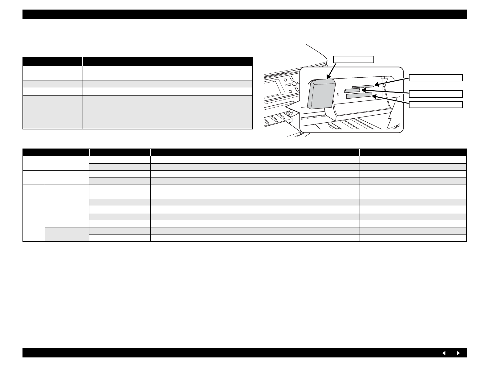
1.2.3.3 Memory Card Slots
Priority Slots Support Memory Card Standards
1 CF Type II
Smart Media/
2
xD-Picture card
Memory Stick
3
SD/MMC
Compact Flash CF+ and CompactFlash Specification Revision 1.4 compliant Only memory cards
Microdrive
Smart Media SmartMedia Standard 2003 compliant Max : 128MB
xD-Picture card xD-Picture Card Specification Version 1.20 compliant * Type M supported Supporting Type M
Memory Stick MemoryStick Standard Version 1.3 compliant
MagicGate Memory Stick Not supporting any copyright protection function
Memory Stick PRO MemoryStick Standard Memory Stick PRO Format Specifications Version 1.0 compliant Not supporting any copyright protection function
Memory Stick Duo Requiring the adapter
Memory Stick Pro Duo Requiring the adapter
SD SD Memory Card Specifications / PART1. Physical Layer Specification Version 1.0 compliant
MMC MultiMediaCard Standard compliant
Max : 128MB
Including the one with memory select function
Note 1: For both PC connection and Directing printing, only one type of media is accessible at the same time.
Priority is assigned to each slot, so that if multiple media are inserted into multiple slots at the same time, an accessible slot is determined in the order of priority.
2: In order to select the medium inserted into an invalid slot, the medium in the valid slot needs to be removed.
3: For direct printing: Only the image files in a valid slot are determined to be valid and photo numbers are assigned to only them. The number of images does not change
even if media are inserted into unselected slots.
4: For PC connection (Windows): Only one “removable disk” drive is displayed; and only the medium in a valid slot can be accessed on the “removable disk.” Media inserted in
unselected slots are not accessible.
5: For PC connection (Macintosh): Only the medium in a valid slot is mounted onto the desktop. Media inserted in unselected slots can not be mounted onto the desktop.
6: Slot selection at power on: When power is turned on with media inserted in multiple slots, an accessible slot is determined in accordance with the above order of priority.
7: Slot selection with power turned on: When the medium is removed from the valid slot, the slot of the second highest priority becomes valid (if a medium is inserted there). It is not
necessary to reinsert the medium before it is accessed. If media are not inserted in any of the slots, the valid slot is changed to the slot of the highest
priority (Compact Flash). This is not affected by the order of media insertion in or removal from unselected slots.
備考
Product Description Basic Specifications 12
Page 12
EPSON Stylus PHOTO RX640/650 Revision A
1.3 Consumables and Options
1.3.1 Ink Cartridges
Table 1-1. Ink Cartridges
Items Specifications
Type Each-color separate ink cartridge
Colors Black, Cyan, Magenta, Yellow, Light Cyan, Light Magenta
-20°C to 40°C (Installed) (Within 1 month at 40°C. An acceptable
Storage temperature
Dimensions 12.7 mm (W) x 73.46 mm (D) x 55.25 mm (H)
Weight 39 g
Note : Ink cartridges cannot be refilled. They are provided as consumable items.
C H E C K
P O I N T
Ink cartridges whose validity has expired should not be used.
The ink in cartridges freezes if left in a temperature of -16°C or
change in temperature is 45°C or less within this range.)
-30°C to 40°C (Packing storage) (Within 1 month at 40°C)
below. To restore frozen ink to a usable condition, it takes
approximately 3 hours, for example, if it is moved from an
environment at -20°C to an environment at 25°C.
1.4 Common Specifications
1.4.1 Electrical Specifications
Primary power input
Table 1-2. Primary Power Input
100-120V model 220-240V model
Rated power supply voltage (V AC) 100-120 220-240
Input voltage range (V AC) 90-132 198-264
Rated current (A) 0.6 A (max. 1.0 A) 0.3A (max. 0.5 A)
Rated frequency (Hz) 50 ~ 60
Input frequency range (Hz) 47 ~ 63
Approx. 22 W
(Standalone copying, ISO10561 Letter Patter, Plain
Power
consumption (W)
Note 1: This product conforms to “Energy Star”.
2: If inactive condition of the printer continues for more than 5 minutes, the status shifts to
the standby status to reduce holding current of the motors.
3: If inactive condition of the scanner continues for more than 15 minutes, power supply to
the scan lamp is stopped.
Low-power Mode Approx. 11 W Approx. 11 W
Sleep Mode Approx. 1.5W Approx. 1.5W
Power Off Mode Approx. 0.2 W Approx. 0.3 W
Insulation resistance
Min. 10 MΩ (between AC line and chassis, test voltage of DC 500V)
Dielectric strength
AC 1000 Vrms, 1 minute or AC 1200 Vrms, 1 second
Paper - A4 Text)
Product Description Consumables and Options 13
Page 13
EPSON Stylus PHOTO RX640/650 Revision A
1.4.2 Safety Standard/EMC
Table 1-3. Safety Standard/EMC
100-120 V version 220-240 V version
Safety standards UL60950
CSA C22.2 No.60950
EMI FCC part15 subpart B class B
CAN/CSA-CEI/IEC CISPR
22 Class B
Safety standards EN 60950
EMC EN 55022(CISPR Pub.22)
1.4.3 Other Model-unique Specifications
None.
1.4.4 Environment Resistance
Table 1-4. Environment Resistance
10 ~ 35°C (operation mode *3)
Temperature
Humidity
Impact
Vibration
-20 ~ 60°C (non-operation mode *1)
1 month when at 40°C, 120 hour when at 60°C
20 ~ 80%, RH (operation mode *2, *3)
5 ~ 85%, RH (non-operation mode *1, *2)
1 G, 1 x 10⁻³ seconds (operating)
2 G, 2 x 10⁻³ seconds (not operating *1)
0.15G 10-55Hz(operating)
0.50G 10-55Hz(not operating *1)
class B
EN61000-3-2
EN61000-3-3
EN55024
AS/NZS CISPR22 class B
1.4.5 Lifetime
Table 1-5. Lifetime
Total print volume 16,000 pages (A4/Letter), or 5 years (the shortest one among these)
Print head lifetime 6 billion shots (per nozzle), or 5 years (the shortest one among these)
Scanner head MCBF 36,000 cycles
1.4.6 Noise
Noise level : Max 42 dB (During copy, ISO7779)
1.4.7 Weight / Physical Specifications
Table 1-6. Weight / Physical Specifications
Weight 9.3 kg
External Dimensions
450 mm x 414 mm x 210 mm (Width x Depth x Height, when closed)
450 mm x 492 mm x 288 mm (Width x Depth x Height, in operation)
1.4.8 Special Operations
With Stylus PHOTO RX640/650, the special operation modes described below are
available by turning the power on with the specified buttons held down.
C A U T I O N
The functions described below, intended for use by service
personnel, must not be opened to users.
*1: When packed for shipping.
*2: No condensation
*3: Under the conditions shown in the chart above
Operation for
Forced Power Off
Power + Stop
(Press Power SW first, and press
both switches for more than seven
seconds)
Table 1-7. Special Operations
Switches Function
Turning the power off forcibly
(processing equivalent to power
down)
Product Description Common Specifications 14
Page 14

OPERATING PRINCIPLES
CHAPTER
2
Page 15
EPSON Stylus PHOTO RX640/650 Revision A
2.1 Overview
This Chapter describes the operating principles of the mechanism and electric circuits
of Stylus PHOTO RX640/650.
2.1.1 Mechanical Components
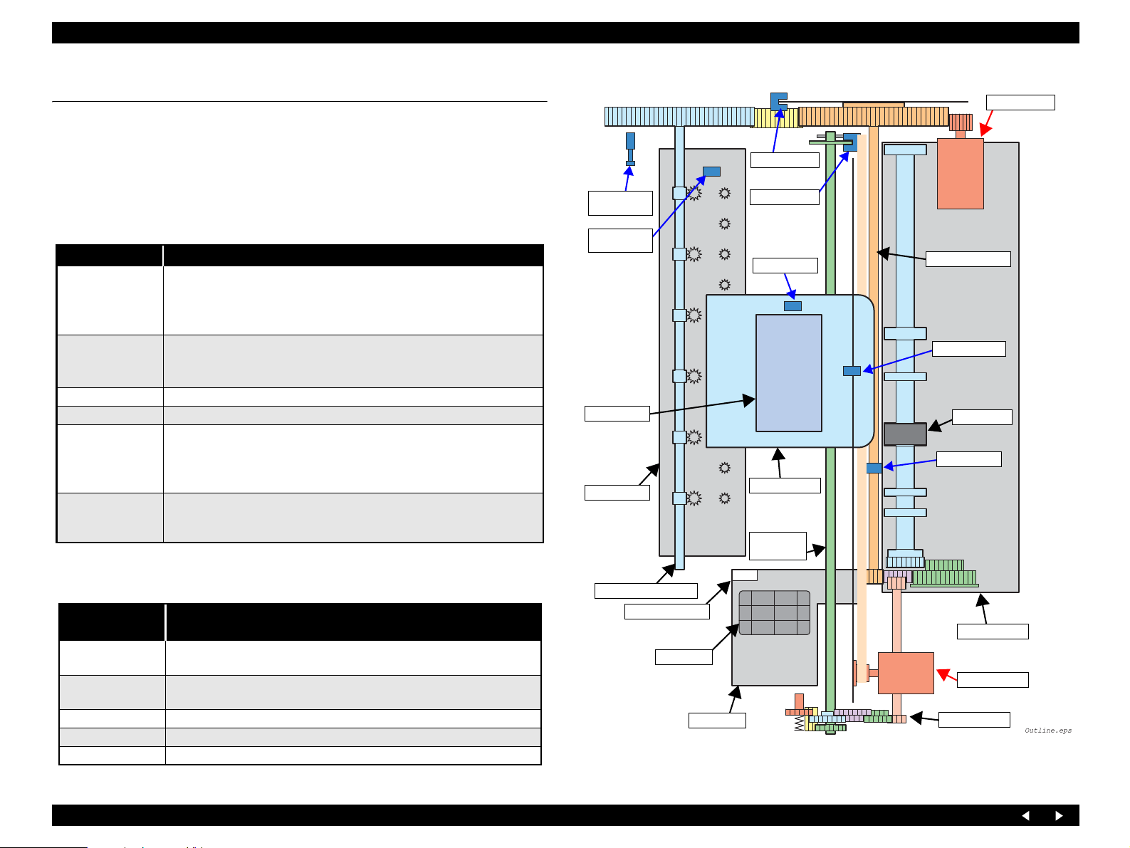
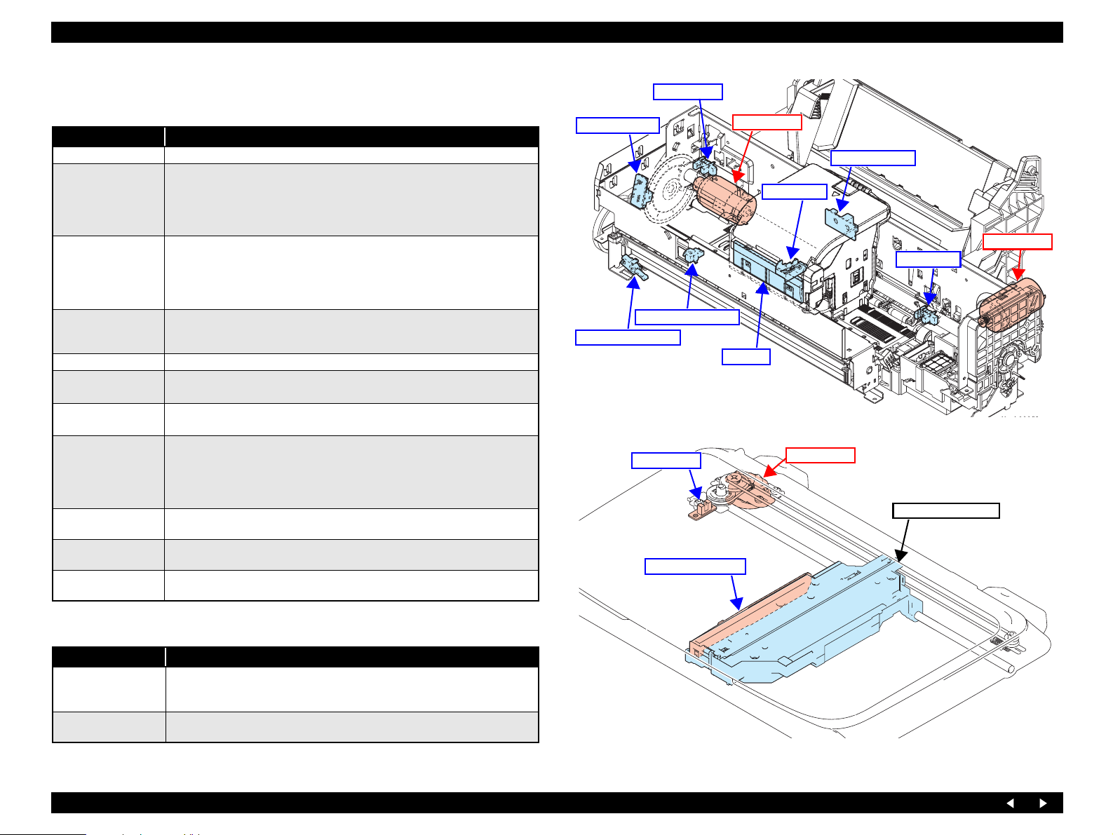
The printer of Stylus PHOTO RX640/650 consists of the following major mechanisms:
Table 2-1. Mechanical Components 1
Mechanism Function/Description
Moves on the CR Guide Shaft right and left and performs printing on
CR Assy
APG Assy
PF Assy Driven by the PF Motor to turn the PF Roller Shaft for feeding paper.
ASF Assy Driven by the PF Motor to load paper into the Printer Mechanism.
Eject Assy
I/S Assy
The units and circuit boards constituting Stylus PHOTO RX640/650 are as follows:
paper.
The Carriage Assy incorporates the Printhead, PW Sensor, and CR
Encoder. The power source is the CR Motor.
Controls the platen gap in four stages.
Detects the current height of the carriage with the APG Sensor, and
moves the carriage up and down, driven by the PF Motor.
Driven by the PF Motor to eject the paper (CD-R Tray).
As the Stacker is moved up and down (by manual operation), the paper
eject frame moves up and down so that its height can be adjusted to the
media.
Located in the right end of the mechanism, performs capping the
Printhead, while it is not used, and sucking waste ink. The waste ink is
sent to the Waste Ink Tray via the Waste Ink Tube.
CD-R Guide
Sensor
CD-R Tray
Sensor
Printhead
Eject Frame
PF Encoder
APG Sensor
PW Sensor
CR Assy
CR Guide
Shaft
PF Motor
PF Roller Shaft
CR Encoder
LD Roller
PE Sensor
Table 2-2. Mechanical Components 2
Unit /Circuit
Board
Main Board
Power Supply
Board
Located on the Middle Housing, incorporating the USB I/F (for PC),
card reader, and infrared communication function.
Located on the Lower Housing. The power cable can be plugged in and
unplugged.
Panel Board Consists of two pieces located on the Middle Housing.
Function/Description
Eject Roller Shaft
CR Lock Lever
Cap Assy
I/S Assy
ASF Assy
CR Motor
APG Assy
USB I/F Board Front USB I/F Board
Scanner Unit Incorporates the film scanner functions.
Figure 2-1. Schematic Printer Mechanism
Operating Principles Overview 16
Page 16
EPSON Stylus PHOTO RX640/650 Revision A
2.1.2 Motors and Sensors
Table 2-3. Motors and Sensors (Printer Mechanism)
Name Function
Printhead F3-MACH head (6 colors x 90 nozzles)
Type : DC motor
CR Motor
PF Motor
PE detector
Ink Cartridge detector CSIC
PTS detector (CR)
PTS detector (PF)
PW detector
APG detector
CD-R Guide detector
CD-R Tray detector
Voltage : 42V DC ± 5% (voltage applied to the driver)
Characteristics Armature resistance : 24.4Ω ± 10%
Inductance : 17.5mH ± 25%
Drive system : PWM system, constant-current chopping system
Type : DC motor
Voltage : 42V DC ± 5% (voltage applied to the driver)
Characteristics Armature resistance : 27.5Ω ± 10%
Inductance : 21.45mH (1kHz)
Drive system : PWM system
Function : Detection of the paper tail end, Paper leading edge positioning
control
Detection method: Transmissive-type photo-interrupter
Type : Linear encoder
Resolution : 1440 pulse/inch
Type : Linear encoder
Resolution : 180 pulses/inch
Function : Paper left and right edge (before and during printing)
Paper top edge (before printing)
Paper bottom edge (during printing)
CD-R top, bottom, right and left edges (before printing)
Detection method: Reflective photosensor
Function : APG position detection
Detection method: Transmissive-type photo-interrupter
Function : CD-R Guide up/down detection
Detection method: Mechanical contact detector
Function : CD-R Tray presence detection
Detection method: Mechanical contact detector
APG Sensor
PF Encoder
CD-R Tray Sensor
CD-R Guide Sensor
Figure 2-2. Motors and Sensors (Front Side of Mechanism)
HP Sensor
CCD Sensor Board
PF Motor
CR Encoder
PW Sensor
CR Motor
PE Sensor
CSIC
CR Motor
CCD Unit (CR Unit)
Table 2-4. Motors and Sensors (Scanner Unit)
Name Function
Type : 2-phase-200-pole PM type stepping motor
CR Motor
HP detector
Voltage : 42V DC ± 5%
Drive system : Bipolar constant-current driving
Function : Carriage home position detection
Detection method: Transmissive-type photo-interrupter
Figure 2-3. Motors and Sensors (Scanner Unit)
Operating Principles Overview 17
Page 17
EPSON Stylus PHOTO RX640/650 Revision A
2.2 Operating Principles of Electric Circuitry
2.2.1 Overview
The major circuit boards of Stylus PHOTO RX640/650 are as follows:
Main Board: C608MAIN
Power Supply Board: C608PSB/C608PSE
Panel Board: C608PNL and C608PNL-B
CCD Unit Board (Scanner): C608ISN
USB I/F Board : I/F Board Assembly
2.2.2 Features
High-Speed SPC is realized without HUB, thanks to employment of USB 2.0
multi-end point.
An SOC incorporating the printer controller, scanner controller, PT controller
and CPU Super Macro is realized.
Only one CPU (SH2A by RENESAS) controls the printer, scanner and PT
section.
Equipped with one 64-Mbit Flash ROM (with 16-bit bus width) and one 32-
Mbit Flash ROM (with 16-bit bus width).
(Flash ROM or MASK ROM is mounted)
Equipped with one 256-Mbit SDRAM (16-bit bus width) for ASIC local
buses, and one 256-Mbit SDRAM (16-bit bus width) for CPU bus.
Low cost of logic power supply and motor drive is realized by employment of
motor drivers with built-in power supply.
The band width is ensured by setting the operating frequency of the local
SDRAM of SOC at 96 MHz.
High-speed processing is ensured because all the processing from scanning to
binarization, Microweave, and image buffer generation is carried out inside
the SOC, without via the CPU bus.
The size of the MW buffer is reduced to 1/3 of the conventional size by
employment of UBEC (Ultra Block Encode).
Equipped with a color LCD (2.5-inch low-temperature poly-silicon TFT
liquid crystal) as a standard feature.
Power consumption is suppressed by executing the following actions at
transition to the power save mode.
• Lowering the supply voltage for main power
• Cutting off the photo-electric current of the photo sensor
• Stopping the motor drive circuit
• Stopping the UDL clock inside the ASIC
• Entering the CPU core low consump tion mode
• High efficiency power supply circuit
• Stopping excitation of the printer mot or
• Stopping the head drive circuit
• Turning off the CCD scanner power supply and stopping the excitation of the
scanner motor
• Turning off the preview monitor
2.2.3 Circuit Board Constitution
Table 2-5. Circuit Board Constitution
Circuit Board Description
Logic circuits (ASIC incorporated in the CPU core, Flash ROM
x 2, and SDRAM x 2)
Interface circuit (USB 2.0, USB 1.1 Host)
System section
Power Supply
section
Main
Board
Printer section
Card ASIC section
Scanner section
Panel Board
ISN Board
LCD Board
RTC circuit
Color LCD interface
Panel interface
IrDA circuit
Regulator circuit
Power switch circuit
Overvoltage protection circuit
Motor control and drive circuits (PF, CR)
Head control and drive circuit
Sensor circuits (PE, PF, PW, APG, CDR 1 and 2)
Logic circuit (ASIC)
Card power supply control circuit
Scanner interface circuit
Motor control and drive circuit (Scanner)
Scanner HP detection interface circuit
TPU interface circuit
Power switch circuit
Switching circuit
LED circuit
CCD control and A/D conversion circuit
Optical sensor circuit
LCD control circuit
LCD module
SDRAM
Operating Principles Operating Principles of Electric Circuitry 18
Page 18

TROUBLESHOOTING
CHAPTER
3
Page 19
EPSON Stylus PHOTO RX640/650 Revision A
3.1 Overview
With Stylus PHOTO RX640/650, almost all troubles can be coped with by following
the instructions given on “EPSON Status Monitor 3” (when connected to the PC) or on
the LCD.
Once an error occurs, the “EPSON Status Monitor 3” will appear as a pop-up window
on the screen of the host PC. It will show details of how to cope with the trouble. In
almost all cases, the user can recover the unit from the error, provided that the user
follows the instructions indicated on the pop-up window.
In addition, the User's Manual for EPSON Stylus PHOTO RX640/650 describes
detailed steps to be taken for recovery from typical errors.
3.1.1 Specified Tools
Stylus PHOTO RX640/650 does not require any specified tools for troubleshooting.
3.1.2 Preliminary Checks
Before starting troubleshooting, be sure to verify that the following conditions are all
met:
The power supply voltage must be within the specification limits. (Measure
the voltage at the wall outlet.)
The POWER CORD must be free from damage, short circuit or breakage, or
miswiring in the POWER CORD.
The Unit must be grounded properly.
The Unit should not be located in a place where it can be exposed to too high
or low temperature, too high or low humidity, or abrupt temperature change.
The Unit should not be located near waterworks, near humidifiers, near
heaters or near flames, in a dusty atmosphere or in a place where the Unit can
be exposed to blast from an air conditioner.
The Unit should not be located in a place where volatile or inflammable gases
are produced.
The Unit should not be located in a place where it can be exposed to direct
rays of the sun.
The Unit must be placed on a strong and steady level table (without an
inclination larger than 5 degrees).
There must be no vibration generating source placed in contact with this Unit.
The paper used must conform to the specification.
There must be no error in handling of the Unit.
Check the inside of the Unit, and remove foreign matters, if any, such as paper
clips, staples, bits of paper, paper dust or toner.
Clean the inside of the Unit and the rubber rolls.
3.1.3 Procedure for Troubleshooting
Perform troubleshooting according to the flowchart shown at below.
START
Perform “3.1.2 Preliminary
Checks (p.20)”.
Does the error recur?
Yes
Is there any error
display?
No
To Troubleshooting for
Individual Units
Flowchart 3-1. Procedure for Troubleshooting
No
Yes
Problem solved
By referring to “3.2
Troubleshooting When There is
Error Display (p.21)”, identify
the error and repair it.
(Also refer to “Troubleshooting”
Troubleshooting for Printer (p.31)
Power Supply Related Troubleshooting (p.35)
Ink Supply Related Troubleshooting (p.35)
I/F Related Troubleshooting (p.37)
Troubleshooting for Scanner (p.38)
Troubleshooting Overview 20
Page 20

EPSON Stylus PHOTO RX640/650 Revision A
3.2 Troubleshooting When There is Error Display
3.2.1 Error List
Table 3-1. Error List
Error Name Occurrence Condition Displayed Message Recovery Procedure
The ink cartridge cover is not closed.
Message related to Ink (1)
Message related to Ink (2)
Message related to Ink (3)
Message related to Ink (4) Ink end.
Scanner FATAL Error
Paper Jam Error A paper jam has occurred.
Paper Empty Error There is no paper in the sheet feeder.
Paper detect error
The ink exchange was executed with the ink cartridge
fixation cover open.
The ink cartridges have not been inserted or defective ink
cartridges have been inserted.
The ink cartridge had not been inserted at an initial filling
or the ink cartridge error occurred.
An error that cannot be recovered on the scanner side
occurred.
A sheet was loaded in a wrong orientation and caused a
jam.
Open the scanner unit and close the ink cartridge cover.
Press OK to continue.
Guide Display “ OK: Continue ”
Ink cartridges cannot be recognized.
Make sure the ink cartridges are correctly installed.
Press OK to continue.
Guide Display “ OK: Continue ”
Ink cartridges cannot be recognized.
Make sure the ink cartridges are correctly installed.
Press OK to continue.
Guide Display “OK: Continue ”
[Color icons]
Ink out.
Press the OK button to replace the cartridges.
Guide Display “ OK: Continue ”
A scanner error has occurred.
Please see your manual.
Guide Display “<Power Button>: Turn off ”
Paper or CD/DVD jam or feed error.
Press the Start button.
If the error does not clear, reinsert the paper or CD/DVD and press
the Start Button.
Guide Display “<Start Button>: Start”
Paper out.
Load paper and press the Start button.
Guide Display “<Start Button>: Start”
Paper jam.
Load paper and press the Start button.
If the error does not clear, repeat the procedure.
Guide Display “<Start Button>: Start”
Close the ink cartridge fixation cover
and press the OK Button.
Install the normal ink cartridges
correctly and press the OK button.
Install the normal ink cartridges
correctly and press the OK button.
Install the normal ink cartridges filled
with ink correctly and press the OK
button.
Turn off the power.
Remove the paper.
Press the “Start” button to load paper
correctly.
Follow the displayed message until the
sheet loaded in a wrong orientation is
ejected.
Troubleshooting Troubleshooting When There is Error Display 21
Page 21

EPSON Stylus PHOTO RX640/650 Revision A
Table 3-1. Error List (continued)
Error Name Occurrence Condition Displayed Message Recovery Procedure
Multi-page Feed Error Multi-page feed error has occurred.
FATAL Error An irrecoverable error has occurred.
Maintenance Error
CD/DVD guide open
(When startup)
CD/DVD guide open
The printer requires maintenance due to waste liquid
overflow or elastomer tube replacement time, etc.
The front tray is in the CD/DVD print position.
Multi-page feed error.
Remove and reload the paper, then press the Start button.
Guide Display “<Start Button>: Start”
A printer error occurred.
Please see your manual.
Guide Display ““Power Button”: Turn off”
Service required. Parts inside your printer are at the end of their
service life. See your manual for details.
Guide Display ““Power Button”: Turn off”
The front tray is in the CD/DVD position.
Pull up the tray lever to set the front tray to the paper position.
Re-set paper and press the “Start” button
to feed paper correctly.
Turn off the power
( Refer to “3.2.3 FATAL Error” (p.28))
Turn off the power
( Refer to “3.2.3 FATAL Error” (p.28))
Pull up the lever to change the print
position to the lower position.
Troubleshooting Troubleshooting When There is Error Display 22
Page 22

EPSON Stylus PHOTO RX640/650 Revision A
3.2.2 Warning List
Table 3-2. Warning List
Causes Details Displayed Message (TBD) Recovery Procedure
In adjustment of borderless
expansion value
Position of CD/DVD guide
(Re-set)
Set the CD/DVD guide
(Set correctly)
Message related to ink (5) A non-genuine ink cartridge has been installed.
BT File size error The document is too large to print with Bluetooth.
BT Designation error The document is too complex to print with Bluetooth.
BT structure error
A part of the reference object
is broken (BT-MIME).
This message is always displayed during
adjustment of the Borderless Expansion Value.
Printer did not recognize the CD/DVD tray
correctly when it was about to start printing.
CD/DVD tray was not in its position when the
printer was about to stat printing,
While XHTML-Print data could be decoded, a part
or all of the reference object had a MIME encode
error and could not be obtained.
The following two problems are considered
depending on the type of the un-obtained reference
object.
For an image, an area where that image is to be
printed becomes blank.
For a CSS (style sheet) file, the background color,
basic character size or the like cannot be specified
as intended at the send side.
You can change the amount of image enlargement.
If you reduce it too much, you may see a white border around your photo.
Guide Display “<OK>: Finish”
The front tray is in the wrong position.
Push down the tray lever to set the front tray to the CD/DVD position.
The CD/DVD tray is set incorrectly.
Set the CD/DVD tray correctly, then press the Start button.
Guide Display “<Start Button>: Start”
The installed ink cartridges listed below differ from the genuine Epson
ink cartridges for this printer.
[Y] [BK] [LC] [LM] [M] [C]
The use of other products may affect your print quality and could result in
printer damage.
Do you want to continue using the currently installed ink cartridges?
[Yes] [No]
Guide Display “<- ->:Make a Selection <OK>: OK”
Error in the data.
The document cannot be printed.
Error in the data.
The document may not be printed correctly.
Press the OK button.
Pull down the lever to change the
print position to the lower position.
Set the CD/DVD tray correctly, and
press the Start button.
Press the OK button
Press the OK button or wait for a
certain time (approx. 5 seconds).
Press the OK button or wait for a
certain time (approx. 5 seconds).
Press the OK button or wait for a
certain time (approx. 5 seconds).
Press the OK button or wait for a
certain time (approx. 5 seconds).
Troubleshooting Troubleshooting When There is Error Display 23
Page 23

EPSON Stylus PHOTO RX640/650 Revision A
Table 3-2. Warning List (continued)
Causes Details Displayed Message (TBD) Recovery Procedure
A part of the reference object
cannot be buffered (BTMIME).
BT communications error
External device installment An unsupported device has been installed.
Menu change or printing
operation with a DSC
connected
Reprint/Restore Photos Cannot recognize the Photos
Film print Cannot recognize the Film
Combo print error 1 (Euro)
Photo Greeting card error 1
(EAI)
Combo print error 2 (Euro)
Photo Greeting card error 3
(EAI)
Photo Greeting card error 4
(EAI)
While XHTML-Print data could be decoded, a part
or all of reference object decoding was abandoned
due to memory shortage or excess of the max.
number of objects to be handled.
An error has occurred in communication with the
BT adapter.
Entering a menu screen for use of memory cards or
starting to print was attempted with a DSC
connected.
No recognition mark could be found on the
template sheet.
No mark is given in the Paper Type or Text Style
selection area, or more than one mark is given.
No mark is given for compose layout, or more than
one mark is given.
No mark is given for compose paper type, or more
than one mark is given.
Error in the data.
The document may not be printed correctly.
Bluetooth print adapter cannot be recognized.
Please remove and reinstall the adapter.
Guide Display “<OK>: Cancel”
Cannot recognize the USB device.
Guide Display “<OK>: Finish”
Camera is connected.
Disconnect the camera and try again.
Guide Display “<OK>: Cancel”
No photos could be recognized. Make sure the photos are positioned
correctly. For details, see your manual.
Guide Display “<OK>: Finish”
A slide or negative could not be recognized.
Make sure the film holder is properly positioned and the film is inserted
in the holder.
For details, see your manual.
Guide Display “<OK>: Finish”
There was an error reading the template.
Check that the template is correctly located on the glass and try again.
Guide Display “<OK>: Finish”
Selection of the text style is not correct.
Please select only one text style and try again.
Guide Display “<OK>: Finish”
The layout has not been selected or the ovals are not marked correctly.
Only one layout may be selected.
Please correct and try again.
Guide Display “<OK>: Finish”
The paper type has not been selected or the ovals are not marked
correctly.
Only one paper type may be selected.
Please correct and try again.
Guide Display “<OK>: Finish”
Press the OK button or wait for a
certain time (approx. 5 seconds).
Remove the BT adapter.
Press the OK button to delete the
message.
Press the OK button
Press the OK button
Press the OK button
Press the OK button
Press the OK button
Press the OK button
Press the OK button
Press the OK button
Troubleshooting Troubleshooting When There is Error Display 24
Page 24

EPSON Stylus PHOTO RX640/650 Revision A
Table 3-2. Warning List (continued)
Causes Details Displayed Message (TBD) Recovery Procedure
Combo print error 5 (Euro)
Photo Greeting card error 5
(EAI)
Index sheet scan error
(no index sheet)
Index sheet scan error
(incorrect image selection
marking)
Index sheet scan error
(incorrect paper selection
marking)
Index sheet scan error
(discrepancy between index
sheet and card)
Scan to memory error
(fail to format)
Scan to memory error
(card removed)
Scan to memory error
(no card)
Scan to memory error
(insufficient card capacity)
Scan to memory error
(card write-protect)
Scan to memory error
(folder not created)
After template printing, a different memory card
was inserted or an image was added or deleted.
No index sheet has been set.
The image selection marking on the index sheet is
not correct.
The paper type selection marking on the index
sheet is not correct.
After index sheet printing, a different memory card
was inserted or an image was added or deleted.
Error has occurred in formatting the card.
The medium has been removed during card
formatting.
Scan to memory was performed with no memory
card inserted.
The memory card capacity is insufficient.
As the memory card was write-protected, save
failed.
A folder could not be created in the memory card.
The contents of the memory card have changed. Print a new template and
try again.
Guide Display “<OK>: Finish”
There is no index sheet or it is not positioned correctly.
Please check it and try again.
Guide Display “<OK>: Finish”
Photos are not selected on the index sheet, or the ovals are not marked
correctly.
Please correct and try again.
Guide Display “<OK>: Finish”
The paper type has not been selected or the ovals are not marked
correctly.
Only one paper type may be selected.
Please correct and try again.
Guide Display “<OK>: Finish”
The contents of the memory card have changed. Print a new index sheet
and try again.
Guide Display “<OK>: Finish”
A problem occurred while formatting.
Formatting canceled.
Guide Display “<OK>: Finish”
The memory card or disk was removed.
Formatting canceled.
Guide Display “<OK>: Finish”
No memory card or Disk inserted.
Save canceled.
Guide Display “<OK>: Finish”
There is not enough free space on the memory card or disk.
Save canceled.
Guide Display “<OK>: Finish”
The memory card or disk is write-protected.
Operation canceled.
Guide Display “<OK>: Finish”
Cannot create a folder on the memory card or disk.
Operation canceled.
Guide Display “<OK>: Finish”
Press the OK button
Press the OK button
Press the OK button
Press the OK button
Press the OK button
Press the OK button
Press the OK button
Press the OK button
Press the OK button
Press the OK button
Press the OK button
Troubleshooting Troubleshooting When There is Error Display 25
Page 25

EPSON Stylus PHOTO RX640/650 Revision A
Table 3-2. Warning List (continued)
Causes Details Displayed Message (TBD) Recovery Procedure
Scan to memory error
(card removed)
Card insertion Recognition of the memory card failed.
Life of waste ink pads is near
end.
A non-supported medium is
inserted
No memory card is inserted.
Memory card print No image is contained in the memory card.
Backup error (no card) Backup source does not exist.
Backup error
(no external connection)
Message of backup cancel
Backup error
(connected to PC)
Backup error (insufficient
external media capacity)
File clearness (Cancel)
File clearness
(Error has occurred.)
File clearness
(Memory card has removed)
Can not saving data, because memory card has been
removed.
The waste ink counter is indicating that the life of
the waste ink pads has been nearly expired.
This is displayed only at power on.
Unformatted or non-supported medium is inserted.
Memory card Mode has been selected with no
memory card inserted.
Backup was about to be started without an external
device connected.
This message is displayed when backup has been
canceled.
Backup was about to be started with the Unit
connected to a PC.
Insufficient capacity of destination media for
backup.
This message is displayed when file clearness is
canceled
An error has occurred in file clearness.
Memory card has been removed during file
clearness.
The memory card or disk was removed. Operation canceled.
Guide Display “<OK>: Finish”
Cannot recognize the memory card or disk.
Guide Display “<OK>: Finish”
Service required. Parts inside your printer are near the end of their service
life.
See your manual for details.
Guide Display “<OK>: Back”
Cannot recognize the memory card or disk. Do you want to format it?
Guide Display “<OK>: Proceed, <Back>: Cancel”
No memory card or disk inserted.
A memory card was inserted.
No photos found.
Guide Display “<OK>: Finish”
No memory card in slot.
Backup canceled.
Guide Display “<OK>: Finish”
External device is not connected or media is not inserted.
Backup canceled.
Guide Display “<OK>: Finish”
Backup canceled.
Guide Display “<OK>: Finish”
Backup cannot be performed when connected to a PC.
Guide Display “<OK>: Finish”
Insufficient space on the backup device.
Backup cannot be performed.
Guide Display “<OK>: Finish”
Operation canceled.
Guide Display “<OK>: Finish”
An error occurred while clearing files.
Operation canceled.
Guide Display “<OK>: Finish”
The memory card or disk was removed. Operation canceled.
Guide Display “<OK>: Finish”
Press the OK button
Press the OK button or wait for a
certain time (approx. 3 seconds).
Initialize the EEPROM or replace the
waste pads and related parts. Or press
“OK: Back”
OK: Format
Back: Not format
Press the OK button or wait for a
certain time (approx. 3 seconds).
Press the OK button
Press the OK button
Press the OK button
Press the OK button
Press the OK button
Press the OK button
Press the OK button
Press the OK button
Press the OK button
Troubleshooting Troubleshooting When There is Error Display 26
Page 26

EPSON Stylus PHOTO RX640/650 Revision A
Table 3-2. Warning List (continued)
Causes Details Displayed Message (TBD) Recovery Procedure
File clearness (Writeprotected)
File clearness
(No memory card)
Head cleaning Failure for insufficient amount of remaining ink
Film mode:
Scan to memory card
Select photos in CD label print. More than one copy has been selected. Only 1 copy can be selected.
Paper type change for CD
printing.
Select the number of copies Plural pieces selection error
Zoom Warning against changing the paper size.
P.I.F. No P.I.F. in memory card. Insert a memory card that contains P.I.F. data.
Memory card print
Because the memory card is write-protected, it is
not possible to delete it.
Because the memory card has not been inserted, it
is not possible to delete the file.
An error due to impossible sorting has occurred.
You are asked if you really desire to clear the
settings.
No image is contained in the memory card or no
memory card has been inserted.
The memory card or Disk is write-protected.
Operation canceled.
Guide Display “<OK>: Finish”
No memory card in slot.
Operation canceled.
Guide Display “<OK>: Finish”
Cannot perform print head cleaning due to low ink level.
Guide Display “<OK>: Finish”
An error occurred while saving.
Save canceled.
Guide Display “<OK>: Finish”
If you change the settings, you must select your photos and number of
prints again.
Guide Display “<OK>: OK, <Back>: Cancel”
Only 1 copy can be selected.
Guide Display “<OK>: Cancel”
If the paper size is changed, the crop area may change.
Do you want to continue? [Yes] [No]
Guide Display “<- ->:Make a selection, <OK>: OK”
Insert a memory card that contains photos.
Press the OK button
Press the OK button
Press the OK button
Press the OK button
Wait for a certain time (approx. 3
seconds).
Press the OK button or “Back”
button.
Press the OK button
Press the OK button
Wait for a certain time (approx. 3
seconds).
Wait for a certain time (approx. 3
seconds).
Troubleshooting Troubleshooting When There is Error Display 27
Page 27
EPSON Stylus PHOTO RX640/650 Revision A
3.2.3 FATAL Error
C H E C K
P O I N T
The EEPROM (Address: 3CH) stores the error code of the
latest fatal error.
The latest fatal error can be identified using the adjustment
program.
In case any fatal error (such as memory check) other than those
in the Printer Mechanism occurs, all the LEDs (x5) flash
without any indication on the LCD. Pressing the Change View
button during flashing will display the error code, so that you
can identify the error from the error code.
Table 3-3. Fatal Errors
Category Error Code Error Cause Remedy
Checking the operation of the Carriage Assy;
Move the Carriage Assy by hand, and check to see if it moves smoothly.
Making the following adjustments
♦Bi-D
♦Paper feed length with PF Assy
♦Paper feed length with Eject Assy
♦PW adjustment
Checking the following parts and replacing the defective one
♦Checking the head FFC (CN6/7) for disconnection or breakage
♦Checking the lead wires of the CR Motor (CN3)for disconnection or breakage
♦Checking the CR Encoder FFC (CN6) for disconnection or breakage
♦Checking the printer frame for adhesion of dirt or insufficient lubrication (p.79)
♦Checking the CR Guide Shaft for adhesion of dirt or insufficient lubrication
♦Checking the Linear Scale for adhesion of dirt or damage (p.52)
♦Checking the CR Encoder for adhesion of dirt or damage (p.67)
♦Checking the PW Sensor for adhesion of dirt or damage (p.67)
♦Checking the CR Belt for damage or improper tension (p.65)
♦Checking the CR Motor and replacing it if necessary (p.65)
♦Main Board (p.46)
♦Power Supply Board (p.54)
DC error
(CR motor)
01H CR PID speed over error
02H CR load positioning lock error
08H CR PID reverse rotation detection error
0AH
0BH CR load positioning speed over error
0CH CR PID lock error
0DH CR PID aveTi max error
CR load positioning accumulation moving
distance error
An error occurred in the CR
motor operating sequence
Troubleshooting Troubleshooting When There is Error Display 28
Page 28
EPSON Stylus PHOTO RX640/650 Revision A
Table 3-3. Fatal Errors (continued)
Category Error Code Error Cause Remedy
DC error
(PF motor)
APG motor
Motor drive
time error
Factory
command
error
FBH PF acceleration lock error
FEH PF speed over error
FAH
Measurement value error in PF Duty
limiting control
EFH Position error in PF BS control
F0H DTY_max error in PF BS control
F2H PF PID drive time-out judgment error
F3H PF BS drive time-out judgment error
70H APG error (normal drive error)
71H APG home seek error
72H Error in APG drive by factory command
D1H
D2H
D3H
D4H
30H
CR (PID) drive time-out
CR (load positioning) drive time-out
PF (PID) drive time-out
PF (BS) drive time-out
Error by EEPROM verify command
An error occurred in the PF
motor operating sequence
An error occurred in the APG
operating sequence
The motor kept operating for
more than the specified time.
Checking the PF mechanism by visual inspection:
Check the PF mechanism for paper jam or adhesion of foreign matters by visual
inspection.
Checking the operation of the PF mechanism:
Operate the PF mechanism by hand, and check to see if it operates smoothly.
Making the following adjustments:
♦Bi-D
♦Paper feed length with PF Assy
♦Paper feed length with Eject Assy
♦PW adjustment
Checking the following parts and replace the defective one:
♦Checking the PF Encoder FFC (CN8) for disconnection or breakage
♦Checking the lead wires of the PF Motor (CN4)for disconnection or breakage
♦Checking the PF scale for adhesion of dirt or damage (p.61)
♦Checking the PF encoder for adhesion of dirt or damage (p.61)
♦Checking the Upper Paper Guides for improper installation (p.69)
♦Checking the PF Motor and replacing it if necessary (p.61)
♦Main Board (p.46)
♦Power Supply Board (p.54)
Checking the installation of the APG Sensor: position of the sensor and connection of
the connector (CN9)
Checking the drive of the APG Assy
♦Installation of the composite gear of the ASF Assy ~APG Assy
♦Standalone operation of the APG Assy
♦Reinstallation of the APG Assy (phase)
Checking the following parts and replace the defective one:
♦APG Assy (p.64)
♦ASF Assy (p.63)
♦APG Sensor
♦PG Left Cam (p.67)
♦Main Board (p.46)
♦Power Supply Board (p.54)
Checking the mechanism and operation
Check the mechanism and operation of the motor in question.
Checking the connection of the connectors and routing of the lead wires
Checking the motor in question and the following parts and replacing the defective part
♦Main Board (p.46)
♦Power Supply Board (p.54)
Checking the following parts and replace the defective one:
♦Main Board (p.46)
♦Power Supply Board (p.54)
Troubleshooting Troubleshooting When There is Error Display 29
Page 29
EPSON Stylus PHOTO RX640/650 Revision A
Table 3-3. Fatal Errors (continued)
Category Error Code Error Cause Remedy
Transistor ambient temperature abnormal
Error in X-Hot detection before printing
Error in X-Hot detection after flushing
Head ambient temperature abnormal
Home seek error
CR unlocking error
CR locking error
Paper detect error before initial charge
completion
PW detection error (Hi check error)
PW detection error (Low check error)
Tray detection (CDR detector 2) error
Paper detection error
Waste ink overflow
The thermistor on the printhead
detected abnormal temperature.
An error occurred in the
carriage operating sequence.
PW detector trouble
Sensor trouble
Life expiration of maintenance
parts
Checking the following parts and replace the defective one:
♦Printhead (p.51)
♦Main Board (p.46)
♦Power Supply Board (p.54)
♦Replace the Head FFC
See Remedy for DC error (CR motor)
Checking the PW Sensor (p.67)
♦Checkingthe PW Sensor for adhesion of dirt and dust
♦Checking the connection of the FFC
Making the following adjustments:
♦PW adjustment
Checking the following parts and replace the defective one:
♦Head FFC
♦Carriage Assy
♦Main Board (p.46)
♦Power Supply Board (p.54)
Checking the operation of the actuator and the connection of the connector.
Checking the following parts and replace the defective one:
♦Sensor
♦Main Board (p.46)
♦Power Supply Board (p.54)
Replace all the maintenance parts, and clear the maintenance counter.
♦Refer to “6.1.1 Maintenance Error” (p.78)
Head system
error
Sequence
error
Sensor error
Maintenance
error
40H
41H
42H
43H
50H
51H
52H
53H
60H
61H
62H
63H
A0H
Troubleshooting Troubleshooting When There is Error Display 30
Page 30
EPSON Stylus PHOTO RX640/650 Revision A
3.3 Troubleshooting When There is No Error Display
3.3.1 Troubleshooting for Printer
This section describes repair/service of the Printer Mechanism. Listed below are various problems which may occur, observations of such problems, check point and remedies.
Faulty paper loading
Table 3-1. Diagnostics when feeder is abnormal
Condition Cause Check Point Remedy
Clean the rollers using a cleaning sheet.
1. Set a cleaning sheet upside down in the ASF Assy.
2. Start paper feed with the panel button.
3. Repeat steps above several times.
To remove oils from rollers, staple a cloth dampened with alcohol to a postcard
and follow the steps below.
1. Set the postcard in the tray with the alcohol dampened cloth side facing the LD
Roller (or Retard Roller).
2. Start paper feed while firmly holding the upper edge of the card.
3. Repeat the paper feed operation several times to clean the surface of the LD Roller
(or Retard Roller).
If these steps do not correct the problem, replace both the LD Roller and Retard Roller.
Wipe the rollers with a cloth dampened with alcohol.
Adjust the phase of the paper loading mechanism.
Remove the dust and dirt, if any.
Connect the PE Sensor connectors to the sensor and Main Board CN10 properly.
Install the Torsion Spring on the PE Lever properly.
Install the tension spring properly.
Paper is not
loaded.
Several sheets of
paper are fed at
the same time
LD Roller and Retard Roller
dirty or worn
Pick Up Roller and Idle
Roller dirty or worn
Operation of paper loading
mechanism is abnormal
PE Sensor/PE Lever
not operating properly
Retard Roller operation is
abnormal
Check to see if no Micro Pearl or oily substance is adhering to
the paper loading roller.
Check to see if no Micro Pearl or oily substance is adhering to
the rollers.
Check to see if there is no abnormality in the paper loading
mechanism.
Check to see if the PE Sensor connector has not been
disconnected from the sensor or Main Board.
Check to see if the Torsion Spring has been set on the PE Lever
properly.
Check for damaged PE Sensor. Replace the PE Sensor.
Check to see if the tension spring on the Retard Roller is
disengaged.
Check to see if the Retard Roller is out of position. Install the Retard Roller properly.
Troubleshooting Troubleshooting When There is No Error Display 31
Page 31

EPSON Stylus PHOTO RX640/650 Revision A
Faulty paper ejection
Table 3-2. Diagnostics when paper ejection is abnormal
Condition Cause Check Point Remedy
Faulty PF-related operation
Paper is jammed on the
way of paper ejection.
PF degradation
compensation counter
Faulty operation of Paper
Eject Roller
Faulty carriage operation
Condition Cause Check Point Remedy
Abnormal carriage
operation during
printing
Carriage does not move
smoothly.
Turn the PF Roller, and check to see if the paper is
transferred to the Paper Eject Rollers properly.
Check the PF degradation compensation counter and the
number of printed sheets using the adjustment program.
Check to see if Paper Eject Roller rotates correctly. Properly engage the gears driving the Paper Eject Roller.
Engage the PF-related gears properly.
Initialize the PF degradation compensation counter and write the maximum value.
Table 3-3. Diagnostics when carriage action is abnormal
Check to see if there is an obstacle in carriage route. Remove the obstacle.
Operate the carriage by hand and check to see if carriage
moves smoothly.
Check tension of timing belt. Replace the Compression Spring of the Driven Pulley Holder.
Move the carriage to the right end and left end fully and
check to see if the length of the Head FFC is proper and
the carriage moves smoothly.
Clean the CR guide shaft and lubricate.
Remove the Head FFC once and reinstall it properly.
Troubleshooting Troubleshooting When There is No Error Display 32
Page 32

EPSON Stylus PHOTO RX640/650 Revision A
Printer stops during initialization
Table 3-4. Diagnostics when printer stops during format
Condition Cause Check Point Remedy
Printer error is
indicated.
Paper Eject Frame not installed
properly
CR Motor not operating
properly
PF Motor not operating
properly
Linear Scale not operating
properly
CR Encoder not operating
properly
Rotary Scale not operating
properly
PF Encoder not operating
properly
Head FFC not operating
properly
Head Hot Error generated Check to see if ink is emitted from all nozzles. If condition does not improve after cleaning, replace the Printhead.
Check to see if the hook securing the Paper Eject Frame has been engaged. Install the Paper Eject Frame properly.
Check for disconnected CR Motor connector. Check the connector (CN3) of the CR Motor.
Check to see if CR Motor coil resistance is as specified. Replace the CR Motor.
Check for disconnected PF Motor connector. Check the connector (CN4) of the PF Motor.
Check to see if PF Motor coil resistance is as specified. Replace the PF Motor.
Check to see if the Linear Scale is traveling through the CR Encoder. Enable the Linear Scale to pass through the CR Encoder.
Check for dirt on Linear Scale. Completely clean the Linear Scale.
Check for damaged Linear Scale. Replace the Linear Scale.
Check to see if Encoder FFC is connected to CR Encoder Board. Connect the Encoder FFC to the CR Encoder Board.
Check for paper bits and dust adhering to CR Encoder. Remove paper bits and dust adhering to the CR Encoder.
Check for damaged Encoder FFC. Replace the Encoder FFC (Carriage Assy).
Check for damaged CR Encoder. Replace the Carriage Assy.
Check to see if the Rotary Scale is not traveling through the PF Encoder. Enable the Rotary Scale to pass through the PF Encoder.
Check for dirt on Rotary Scale. Completely clean the Rotary Scale.
Check for damaged Rotary Scale. Replace the Rotary Scale.
Check to see if Encoder FFC is connected to PF Encoder Board. Connect the Encoder FFC to the PF Encoder Board.
Check for paper bits and dust adhering to PF Encoder. Remove paper bits and dust adhering to the PF Encoder.
Check for damaged Encoder FFC. Replace the Encoder FFC.
Check for damaged PF Encoder. Replace the PF Encoder.
Check for disconnected Head FFC.
Check for damaged Head FFC. Replace the Head FFC.
Firmly connect the Head FFC to the Main Board CN6 ~7 and to the
Printhead.
Troubleshooting Troubleshooting When There is No Error Display 33
Page 33

EPSON Stylus PHOTO RX640/650 Revision A
Faulty print
Table 3-5. Diagnostics when printing is abnormal
Condition Cause Check Point Remedy
Improper printing
occurs only with
specific dots
Dot missing
sometimes occurs
Print is not as
intended
Vertical lines are
not in alignment
White lines appear
in output data
Printhead surface is dirty
(Dot missing)
Capping absorbent material is in contact
with Printhead surface
Head FFC not operating properly Check for damaged Head FFC. Replace the Head FFC.
Printhead not operating properly Alternate cleaning and nozzle check several times. If condition does not improve after cleaning, replace the Printhead.
Printhead surface is dirty
(Dot missing)
Ink Cartridge not operating properly Install a new ink cartridge and perform nozzle check. Replace the ink cartridge.
Faulty connection inside the Head FFC Use a tester to check the FFC. Replace the Head FFC.
Printhead not operating properly Repeat cleaning several times, and then perform nozzle check. If condition does not improve after cleaning, replace the Printhead.
Head FFC is not connected
Printhead not operating properly Check connection of Head FFC to Printhead.
Bi-D adjustment is not made Check to see if Bi-D adjustment has been done properly. Perform Bi-D adjustment.
Dirt is adhering to CR Guide Shaft Check for dirt adhering to surface of CR Guide Shaft. Clean the surface of the CR Guide Shaft with a soft dry cloth.
PF Roller not operating properly
Ink Cartridge not operating properly Install a new ink cartridge and test printing. Replace the ink cartridge.
Carriage Slide not moving properly
Platen Gap not set properly Check to see if platen gap adjustment has been done properly. Adjust platen gap. ( See “5.1.2 PG Adjustment” (p.73) )
Gear is damaged
Dot jet direction is angled due to dirt on
Printhead surface
Printhead not operating properly Repeat cleaning several times, and then perform test print. Replace the Printhead.
CR Guide Shaft not operating properly
Alternate cleaning and test printing several times. Clean the Printhead surface with a cotton swab.
Check for deformed or damaged capping absorbent material. Replace the Ink System Assy.
Alternate cleaning and nozzle check several times. Clean the Printhead surface with a cotton swab.
Check to see if FFC is firmly connected to each board and
Carriage Assy.
Check for dirt on PF Roller. Carefully clean the surface of the PF Roller with a soft brush.
Check for damaged PF Roller. Replace the PF Roller.
Check to see if sufficient grease is remaining on carriage slide
parts at back of main frame.
Check for abnormality in gears between PF mechanism and ASF
mechanism.
Alternate cleaning and test printing several times. Clean with a cotton swab.
Check for dust and dirt on Cleaner Blade. Clean or replace the Cleaner Blade.
Check to see if CR Guide Shaft is firmly installed in specified
position.
Check for damage to surface of CR Guide Shaft. Replace the CR Guide Shaft.
Connect the FFC firmly.
If there is no problem with the Head FFC to Printhead connection,
replace the Printhead.
Clean the main frame carriage slide parts and lubricate with a specified
quantify of G-71.
( See “ Lubrication at Installation of Carriage Assy” (p.80) )
Replace the damaged parts.
Reassemble the CR Guide Shaft.
Troubleshooting Troubleshooting When There is No Error Display 34
Page 34

EPSON Stylus PHOTO RX640/650 Revision A
3.3.2 Power Supply Related Troubleshooting
If the printer does not operate at all (LED does not light up) even with the power turned ON, refer to the following t a ble and perform troubleshooting.
Table 3-6. Power Supply Related Troubleshooting
Cause Check Point Remedy
Defective power cord Connect the normal power cord. Replace the power cord.
Abnormal AC power
voltage
Faulty connection of the
connector
Fuse blown Check the fuse (F1) on the Power Supply Board. Replace the Power Supply Board with a new one.
Abnormal output voltage of
Power Supply Board
Check the AC power voltage. Supply the normal power.
Check the connection between the Power Supply Board
~ Main Board (CN20).
Check the output voltage of the Power Supply Board.
Correct the connection.
When the output voltage is normal: Replace the Main Board with a new one.
When the output voltage is abnormal: Replace the Power Supply Board with a new one.
3.3.3 Ink Supply Related Troubleshooting
Printer stops during initialization or printing.
Table 3-7. Troubleshooting for Printer Stop During Initialization or Printing
Condition Cause Check Point Remedy
Ink End error is
displayed.
No Ink Cartridge error is
displayed.
Ink Cartridge Trouble
error is displayed.
Ink is out. Check to see if ink is remaining in all the ink cartridges. Replace the ink cartridge.
Not all the ink cartridges
have been installed.
Ink cartridge is damaged.
Check to see if all the ink cartridges have been installed
in the I/C holders.
Check to see if no ink cartridge is in a raised position. Install the ink cartridge properly.
The front or back hook of an ink cartridge is broken. Replace the ink cartridge.
Check to see if the CSIC Board is not dislocated. Replace the ink cartridge.
Check to see if no chip on the CSIC Board is chipping. Replace the ink cartridge.
Install all the ink cartridges.
Troubleshooting Troubleshooting When There is No Error Display 35
Page 35

EPSON Stylus PHOTO RX640/650 Revision A
Printing is not carried out correctly.
Table 3-8. Diagnostics when printing is erratic
Condition Cause Check Point Remedy
Ink Cartridge not operating
properly
FFC not connected properly
Carriage moves
correctly but printing is
not normal.
Cleaner Blade not operating
properly
FFC internal disconnection Check each FFC with a circuit tester. Replace the FFC.
Faulty Printhead Alternate cleaning and test printing several times.
Ink leakage or clogging
with ink
Waste ink is not discharged properly
Condition Cause Check Point Remedy
Pump tube collapsed Visually check tube. Replace the Ink System Assy
Cap is dirty or damaged.
Ink is not flowing from
Printhead to Cap or from
Cap to Ink Tube
Tube is disconnected from
Cap bottom
Cap does not slide up
properly
Tube between the Waste Ink
Tray Assy ~I/S Assy
collapsed
Install a new ink cartridge and test printing. Replace the ink cartridge.
Check the FFC connection between each CSIC Board ~
Main Board.
Check for debris adhering to Cleaner Blade. Clean or replace the Cleaner Blade.
Check to see if there is ink leakage from the Printhead.
Connect the FFC firmly.
When the condition is not improved even after cleaning, replace the Printhead with a
new one.
Install the ink cartridges properly.
If this does not improve the condition, replace ink cartridges and the Printhead.
Table 3-9. Troubleshooting for Faulty Ink Supply or Faulty Waste Ink Discharge
Check for foreign object adhering to Cap or damaged
Cap.
Visually check for disconnection of tube from Cap
bottom.
Check for installation of compression spring on tube
assembly.
Check the tube connection on the bottom of the Waste
Ink Tray Assy and the tube route under the tray.
Remove foreign object from the Cap with cotton swab. If Cap is damaged, replace the
Ink System Assy.
Connect the tube properly.
Replace the Ink System Assy with a new one.
Connect the tube of the Waste Ink Tray Assy properly, and route the tube properly.
Troubleshooting Troubleshooting When There is No Error Display 36
Page 36

EPSON Stylus PHOTO RX640/650 Revision A
3.3.4 I/F Related Troubleshooting
This section describes the troubleshooting for the USB I/F and Memory Card Slot.
USB I/F error
Table 3-10. USB I/F Error
Cause Check Point Remedy
On Windows, open “My
Host PC does not
support Windows
98 essentially.
Printer driver is not
installed correctly.
Defective USB
cable
Poor contact
Defective main
board
computer”
→“Property”
→“Device manager”.
“Universal serial bus controller”
is effective?
On Windows, open “My
computer”
→“Property”
→“Device manager”.
Printer driver is not installed in
“Other devices”?
Operation is normal if USB
cable is replaced?
Check to see if there is no
adhesion of foreign matters in
the USB interface connector.
Check to see if main board is not
damaged.
Remove the USB driver, and install it
again.
Delete the driver and install it again
according to operation manual.
Replace the USB cable.
Remove the foreign matters, and clean
the contact.
Replace the main board.
Troubleshooting for Memory Card Slot
Table 3-11. Troubleshooting for Memory Card
Cause Check Point Remedy
Driver has not been
installed correctly.
Data has been
destroyed.
A memory card
other than those
specified is used.
Memory Card is
faulty.
Poor contact.
Firmware has
abnormality.
Electric noise, etc.
has been
generated.
Defective main
board
Check to see if a memory card is
recognized in the single Assy
mode.
Data on card may be destroyed
owing to static electricity.
Check the card to see if it is one
of the specified cards.
Check to see if another Memory
Card can be recognized.
Check to see if foreign matters
are not adhering to Memory
Card or slot.
– Upload firmware.
Check to see if FFC is connected
correctly and Ferrite Core is
positioned in place inside the
printer.
Check to see if main board is not
damaged.
Temporarily remove the driver, and then
install it again.
Check to see if card data is read by a PC.
If not, format the card.
Use a memory card specified.
Use a new Memory Card.
Remove the foreign matters, and clean
the contact.
After the confirmation, if they have no
abnormality, replace the main board.
Replace the main board.
Troubleshooting Troubleshooting When There is No Error Display 37
Page 37

EPSON Stylus PHOTO RX640/650 Revision A
3.3.5 Troubleshooting for Scanner
This section describes repair/service for the Scanner mechanism. In troubleshooting,
first identify the trouble at the Assy level based on the observation.
According to the observation as described in Table 3-13, perform the necessary
checking by referring to the appropriate table.
Scanner Errors at User Level
Table 3-12. Scanner Errors at User Level
Error Cause Remedy
Scanner error • Lamp has burnt out.
• Power is turned on without
unlocking the scanner.
• The scanner carriage is
interfering with any other part.
Command error Undefined command is detected. When correct command is received, error
Scanner open Scanner cover is open. Close the cover.
Observation of Trouble and Reference for Remedy
Table 3-13. Observation of Trouble and Reference for Remedy
Observation Description of Trouble
Even with power turned on, the
machine does not operate.
“Fatal error” occurred.
Indication error occurs and it is not
cleared even after power is turned off
once and then turned on again.
Picture is not read clearly. Picture is not read clearly. Table 3-19
“Communication error”.
Indication error occurs and when
communication with the host is tried
again, “Communication error” recurs.
The machine does not operate for
initialization.
CR unit does not operate. Table 3-15
CR unit operates but error is indicated. Table 3-16
The fluorescent lamp does not turn on.
USB interface error
• Unlock the CR.
• Replace the scanner carriage Assy.
• Remove the obstacle.
status is cancelled.
Turn the power off once and then turn it on
again.
Reference for
Remedy
Table 3-14
Table 3-17
Table 3-10
Scanner does not operate for initialization
Table 3-14. Scanner does not operate for initialization
Cause Check Point Yes/No Remedy
Connector is disconnected. 1. Check each connector
for disconnection. Is
there any connector
disconnected?
Connect the disconnected
Yes
connector.
Replace the main board.
No
Carriage unit does not operate
Table 3-15. Carriage unit does not operate
Cause Check Point Yes/No Remedy
Connector on the Main
Board is disconnected
Faulty carriage moving
mechanism
Defective CR HP Board Replace the CR HP sensor
Faulty CR motor Disconnect connector CN5
Defective main board – – Replace the main board.
Is any of the connectors
(CN5, 12 and 14) on the
Main Board
disconnected?
Grease is applied properly?
Does CR motor operate
when power is turned
ON with upper case of
Scanner removed?
Does CR unit move with
CR motor removed?
board
on CR HP sensorboard
and measure with a tester
the continuity between pins
2 and 4 and between 1 and
3 on motor side.
Connect the connector.
Yes
Apply grease at designated
No
point ( Refer to “6.1.3
Lubrication” (p.79)
Check the carriage moving
mechanism, replace the
relevant parts or remove
No
and reinstall them.
Replace the CR HP sensor
No
board.
Replace the CR motor.
No
Troubleshooting Troubleshooting When There is No Error Display 38
Page 38

EPSON Stylus PHOTO RX640/650 Revision A
Carriage operates but error indicated
Table 3-16. Carriage operates but error indicated
Cause Check Point Yes/No Remedy
Upper case of scanner is
removed.
Defective main board – – Replace the main board
Defective CR HP sensor
Upper case of scanner is
removed.?
– –
Install the upper case.
Yes
Replace the CR HP sensor
board.
Fluorescent lamp does not turn on
CCD Unit
Table 3-17. Fluorescent lamp does not turn on
Cause Check Point Yes/No Remedy
Connector on the Main
Board is disconnected
Defective lamp or Inverter
Board
Defective main board – – Replace the main board
Connector CN12 on main
board is disconnected?
Does the lamp light up
when the CCD Unit is
replaced?
Connect the connector
Yes
CN12 on the main board.
Replace the CCD Unit.
Yes
TPU Unit
Table 3-18. Fluorescent lamp does not turn on
Cause Check Point Yes/No Remedy
Connector is disconnected Is the connector (CN13) on
the Main Board or either of
the connectors (CN1 and 2)
on the Inverter Board
disconnected?
Defective or life-expired
lamp
Defective Inverter Board Is problem solved when the
Defective main board – – Replace the main board
Does the lamp light up
when it is replaced?
Inverter Board is replaced?
Connect the connector
Yes
Replace the TPU Case
Yes
Assy.
Replace the Inverter Board.
Yes
Picture can not be read clearly
Table 3-19. Picture can not be read clearly
Cause Check Point Yes/No Remedy
Soiled document table Is the document table
(glass) free from dirt and
wiping mark?
Defective CCD Unit – – Replace the CCD Unit.
Defective main board – – Replace the main board
Clean the document table.
No
3.3.6 Troubleshooting for Motors and Sensors
Motor
Table 3-20. Motor Resistance and Check Points
Motor Name Location Check Point Resistance
CR motor CN3 (White) Pin 1 & 2 24.4Ω ± 10%
PF motor CN4 (Black) Pin 1 & 2 27.5Ω ± 10%
CR motor (Scanner Unit) CN5 (White)
Sensor
Table 3-21. Sensor Check
Sensor Name Location Signal Level Sensor Status
PE sensor CN10 Pin 2 & 3
APG sensor CN9 Pin 2 & 3
CD-R Guide sensor
CN11 Pin 1 & 2
Pin 3 & 4
CD-R Tray sensor
2.4 V or over Paper absent
Less than 0.4 V Paper present
2.4 V or over PGposition
Less than 0.4 V Out of PG position
Open:
2.4 V or over
Close:
Less than 0.4 V
Open:
2.4 V or over
Close:
Less than 0.4 V
Pin 1 & 3
Pin 3 & 4
CD-R Tray present
CD-R Tray absent
CD-R Guide down
CD-R Guide up
Note : Refer to “2.1.2 Motors and Sensors” (p.17) for the locations of the motors and sensors.
Troubleshooting Troubleshooting When There is No Error Display 39
Page 39

DISASSEMBLY AND ASSEMBLY
CHAPTER
4
Page 40

EPSON Stylus PHOTO RX640/650 Revision A
4.1 Overview
This section describes procedures for disassembling the main components of the
product.
Unless otherwise specified, disassembled units or components can be reassembled by
reversing the disassembly procedure.
4.1.1 Precautions
See the precautions given under the heading “WARNING” and “CAUTION” in the
following column when disassembling or assembling the product.
Things, if not strictly observed, that could result in injury or loss of life are described
under the heading “Warning”.
Precautions for any disassembly or assembly procedures are described under the
heading “CAUTION”.
Chips for disassembling procedures are described under the heading “CHECK
POINT”.
If the assembling procedure is different from the reversed procedure of the
disassembling, the procedure is described under the heading “REASSEMBLY”.
Any adjustments required after disassembling the units are described under the heading
“ADJUSTMENT REQUIRED”.
When you have to remove any units or parts that are not described in this chapter, refer
to the exploded diagrams in the appendix.
C A U T I O N
When using compressed air products; such as air duster, for
cleaning during repair and maintenance, the use of such
products containing flammable gas is prohibited.
Use only recommended tools for disassembling, assembling or
adjusting the Stylus PHOTO RX640/650.
Observe the specified torque whe n tightening screws.
Make the specified adjustments when you disassemble the
Stylus PHOTO RX640/650. (See Chapter 5 for details.)
Use the special package for transportation.
Prior to disassembly and reasse mbly, remove the accessories,
such as memory cards.
When removing or installing exterior parts, take great care that
no coated surface is scratched and no coating is peeled off.
4.1.2 Tools
Use only specified tools to avoid damaging the Stylus PHOTO RX640/650.
Table 4-1. Tools
Name Availability Tool Code
Phillips precision screwdriver
Phillips precision screwdriver
Tweezers
Note : “{” : available on the market
“EPSON” : available from EPSON
EPSON 1080530
EPSON 1080532
EPSON 1080561
Read precautions described in the next section before starting.
4.1.3 Preparation before Disassembly
Make the following preparations before disassembling the Stylus PHOTO RX640/650:
W A R N I N G
Disassembly and Assembly Overview 41
Remove the batteries and unplug the AC adapter before
disassembling the Stylus PHOTO RX640/650.
Always wear gloves for disassembly and reassembly to avoid
injury from sharp metal edges.
To protect sensitive microprocessors and circuitry, use static
discharge equipment, such as anti-static wrist straps, when
accessing internal components.
When the Main Board is to be replaced, make a copy of the EEPROM data.
When the Carriage Assy is to be moved out of its home position, locate it at a
position other than the home position before starting disassembly by turning the
power ON and turning it OFF timely.
As soon as the repaired product has been returned to the user, there may be a case
a maintenance call occurs because of the expiration of the life of a service part.
Avoid such a case, if possible, as follows: Check the maintenance counter for
regularly replaced parts before disassembly. If the life of any part is found almost
expired, communicate with the user to that effect. If the user's consent is obtained,
replace also the relevant service parts with new ones.
Page 41

EPSON Stylus PHOTO RX640/650 Revision A
4.1.4 Disassembly and Reassembly Procedure
The flowchart below shows step-by-step disassembly procedure for Stylus PHOTO RX640/650. When disassembling each component, refer to the page number indicated for the
relevant component.
START
Disassembly of Panel Assy
(p.44)
Disassembly of Scanner Unit
(p.57)
PF Scale and PF Encoder
(p.61)
PF Motor
(p.61)
Upper Paper Guides
(p.69)
Panel Assy
(p.43)
Scanner Unit
(p.45)
Main Board
(p.46)
Middle Housing
(p.48)
Printer Mechanism
(p.53)
I/S Assy
(p.62)
ASF Assy
(p.63)
CR Motor
(p.65)
Printhead
(p.51)
Linear Scale
(p.52)
Power Supply Board
(p.54)
APG Assy
(p.64)
Waste Ink Tray Assy
(p.50)
Stacker Assy
(p.55)
Eject Frame Assy
(p.68)
Waste Ink Pads
(p.54)
Carriage Assy
(p.66)
Paper Guide Front Assy
(p.70)
Flowchart 4-1. Disassembly Procedure
Disassembly and Assembly Overview 42
Page 42

EPSON Stylus PHOTO RX640/650 Revision A
4.2 Removal of Exterior Parts
4.2.1 Panel Assy
1. Open the Scanner Unit, and remove the screws (x3) securing the Middle Cover
Assy. (Fig. 4-1)
2. Release the hooks (x3 at points marked with ∆) on the Printer Mechanism, the
hooks (x5) in the front and the hook at the right side, and remove the Middle Cover
Assy.
3. Release the hooks at the right and left ends from the direction of the back of the
panel, raise the decorative panel, release all the hooks carefully and remove the
decorative panel. (Fig. 4-2)
4. Remove the screws (x2) securing the Panel Assy. (Fig. 4-3)
5. Lift the Panel Assy, and disconnect the FFCs (x2).
Install the decorative panel, taking care not to confuse the
front and back of the Light Conduction Tubes. (Fig. 4-4)
When installing the Middle Cover, take care not to catch the
Head FFC. If possible, move the carriage to the left
beforehand. (Fig. 4-4)
Hook(x3)
Hook (x10)
Figure 4-2. Removing the Decorative Panel
C.B.P-TITE 3x8 (x2)
Torque : 0.6±0.1N·m
Light Conduction
Tubes
Disconnect
CN15
C.B.P-TITE 3x10 (x3)
Torque : 0.6±0.1N·m
Hook (x5)
Figure 4-1. Removing the Middle Cover Assy
Figure 4-3. Removing the Panel Unit
Light Conduction Tubes
Position the thinner
tip upward
Middle Cover
Install it in front of
the Head FFC
Align
Figure 4-4. Notes on Installing the Panel Assy
Disassembly and Assembly Removal of Exterior Parts 43
Page 43

EPSON Stylus PHOTO RX640/650 Revision A
4.2.2 Disassembly of Panel Assy
C A U T I O N
1. Remove the Panel Assy. (p. 43)
2. Remove the screws (x6) securing the Shield Plate, Panel Board and Ground Plate,
and remove the Shield Plate upward. (Fig. 4-5)
3. Release the hooks, and remove the Panel Board. (Fig. 4-6)
4. Remove the screws (x4), and remove the LCD Module. (Fig. 4-7)
Do not use any cleaning liquid to clean the LCD. Otherwise, the
surface membrane can come off.
For cleaning, blow off the dust with a blower.
When installing the LCD Module, make sure that the inside of
the LCD Cover is free from dust and dirt.
Tighten the screws for the LCD Module in the order specified.
(Fig. 4-7)
After installing the LCD Module, route the harness as shown
and make sure that it is free from floating. (Fig. 4-7)
Install the Shield Plate under the board-to-board cable.
When installing the Shield Plate, tighten the screws in the order
specified. (Fig. 4-5)
After installing the Shield Plate, press each of the buttons and
check that a click is felt.
C.B.P-TITE 3x8
Torque : 0.6±0.1N·m
1 2
Ground Plate
C.B.P-TITE 3x8 (x5)
Torque : 0.6±0.1N·m
56
43
Shield Plate
Figure 4-5. Removing the Screws (Shield Plate)
Hook (x2)
Figure 4-6. Removing the Panel Board
Route the lead wires so that they are free from floating
2 3
14
LCD Module
C.B.P-TITE 2x8 (x4)
Torque : 0.4±0.1N·m
Figure 4-7. Removing the LCD Module
Disassembly and Assembly Removal of Exterior Parts 44
Page 44

EPSON Stylus PHOTO RX640/650 Revision A
4.2.3 Scanner Unit
1. Remove the Panel Assy. (p. 43)
2. Remove the Paper Support.
3. Lift the joint area of the USB Cover and remove the USB Cover by pulling it
toward you. Then remove the light-shield foam. (Fig. 4-8)
4. Disconnect the following FFCs and cables from the Main Board. (Fig. 4-9)
CN No. Color Connected to Remarks
CN5 White CR Motor Unit 4-pin (With ferrite core)
CN12 (FFC) CCD Unit 28-pin (With ferrite core)
CN13 Red TPU Unit 2-pin
CN14 Yellow HP Sensor 3-pin
5. Remove the screw securing the grand wire of the scanner.
6. Close the Scanner Unit, and remove the screws (x2) in the rear. (Fig. 4-10)
7. Remove the Scanner Unit, kept in the open position, from the printer body.
Put the FFC into the housing as shown. (Fig. 4-11)
Put the clamp portion of the black harness (red: CN 13) of the
TPU Unit into the printer body. (Fig. 4-11)
Route the harness as shown and set the ferrite cores in place,
and then stick the acetate tape. (Fig. 4-9)
Figure 4-9. Disconnecting the cables (Scanner Unit)
C.B.P-TITE 3x10 (x2)
Torque : 0.6±0.1N·m
Guide
Ferrite Core
C.B.P-TITE 3x8
Torque : 0.6±0.1N·m
CN13
CN5
Place the harness in consideration
of Middle Cover position
Ferrite Core
CN14 CN12
Tighten the screw while locating
the grounding wire so that it will
not come in contact with the
Middle Cover, which is to be
installed afterwards
Figure 4-10. Removing the Scanner Unit
Place the CR Motor harness
USB Cover
Lift the joint area and
pull the cover toward you
(CN5) on the light-shield foam
Harness of the TPU Unit
Remove
Clamp position
Light-shield foam
Insert the FFC
Figure 4-8. Removing the USB Cover
Figure 4-11. Joint Area with the Printer
Disassembly and Assembly Removal of Exterior Parts 45
Page 45

EPSON Stylus PHOTO RX640/650 Revision A
4.2.4 Main Board
A D J U S T M E N T
R E Q U I R E D
1. Remove the Panel Assy. (p. 43)
2. Remove the Ferrite Core Holder for the Head FFC. (Fig. 4-13)
3. Disconnect all the FFCs and connectors from the Main Board.
4. Remove the ferrite core for the Control Panel FFC from the holder, and remove the
holder from the Shield Plate M/B. (Fig. 4-13)
5. Remove the screws (1+1), and remove the USB Host Assy.
6. Remove the screws (4+1), and remove the Main Board Assy. (Fig. 4-14)
7. Remove the screws (x2), and remove the Shield Plate and Shield Plate M/B
Support. (Fig. 4-15)
8. Remove the screws (x3), and remove the Main Board. (Fig. 4-15)
(йьЗГЙyЕ[ЙWЗчл±З¦)
When the Main Board is to be replaced, back up the data in
EEPROM before starting disassembly, if possible. After assembly,
make the following adjustment.
5.1.1 Adjustment by Use of Adjustment Program (TBD) (p.72)
Head FFC
Ferrite Core Holder
Raise this area and
slide the holder
Cut
Figure 4-13. Removing the Ferrite Core Holder
C.B.S-TITE 3x8 Torque : 0.8±0.1N·m
USB Host Assy
C.B.P-TITE 3x10 Torque : 0.6±0.1N·m
Ferrite Core Holder
Release the hook and
slide the holder laterally
C.B.S 3x8
Torque : 0.8±0.1N·m
3
C.B.P-TITE 3x10 (x4)
Torque : 0.6±0.1N·m
4
5
1
2
Figure 4-14. Removing the Main Board Assy
Shield Plate M/B
Shield Plate
M/B Support
1
C.B 3x12
Torque : 0.8±0.1N·m
2
3
C.B.S-TITE 3x8 (x2)
Torque : 0.8±0.1N·m
Figure 4-12. Main Board Layout
C.B.S-TITE 3x8
Torque : 0.8±0.1N·m
C.B. 3x8
Torque : 0.8±0.1N·m
Figure 4-15. Removing the Main Board
Disassembly and Assembly Removal of Exterior Parts 46
Page 46

EPSON Stylus PHOTO RX640/650 Revision A
Tighten the screws in the order specified to secure the Main
Board and Main Board Assy. (Fig. 4-15, Fig. 4-14)
Route the harness along the guide in th e left area of the
housing, set the ferrite cores in the locations shown, and stick
acetate tape on the ferrite cores. (Fig. 4-17)
CN13 CN5
CN No. Color Connected to
CN2 Red USB I/F Board 4-pin (With ferrite core)
CN3 White CR Motor 2-pin (With ferrite core)
CN4 Black PF Motor 2-pin (With ferrite core)
CN6 (FFC) Printhead 28-pin (With ferrite core)
CN7 (FFC) Printhead 25-pin (With ferrite core)
CN8 (FFC) PF Encoder 5-pin (With ferrite core)
CN9 Black APG Sensor
CN10
CN11 White CD-R Sensor (Guide & Tray) 4-pin
CN15 (FFC) LCD 8-pin
CN16 (FFC) Panel Board 11-pin (With ferrite core)
CN20 White Power Supply Board 3-pin
C H E C K
P O I N T
White PE Sensor
The methods for unlocking the carriage (moving the carriage from
its home position) are as follows:
3-pin (With ferrite core)
3-pin (With ferrite core)
Remarks
While the printer is operating, turn power OFF by unplugging
the AC cable so that the carriage is shifted from its home
position.
Turn by hand the EJ roller gear at the left side of the printer.
(Take care not to get injured with any nearby sheet metal
part.)
CN20CN3 CN4CN11CN8
CN9CN10
CN2
CN7
CN6
CN16CN15
Figure 4-16. Connection of the Connectors on the Main Board
CN8
CN10
CN9
CN4
CN2
Carriage Lock Lever
CN3
Figure 4-17. Routing the Harness and Setting the Ferrite Cores
Disassembly and Assembly Removal of Exterior Parts 47
Page 47

EPSON Stylus PHOTO RX640/650 Revision A
4.2.5 Middle Housing
C A U T I O N
1. Remove the Panel Assy. (p. 43)
2. Remove the Scanner Unit. (p. 45)
3. Remove the Main Board. (p. 46)
4. Remove the Stacker Cover from the right and left supports. (Fig. 4-18)
5. Remove the screws (x2) securing the Waste Ink Assy.
(Do not remove the tube) (Fig. 4-19)
6. Remove the screw and remove the Hinge Assy (left and right). (Fig. 4-19)
7. Remove the screws (3 in the front and 2 in the rear) securing the Middle Housing
Assy. (Fig. 4-20)
8. Remove the Middle Housing Assy, taking care not to damage any cables or the
Waste Ink Assy.
(йьЗГЙyЕ[ЙWЗчл±З¦)
After removing the Waste Ink Assy, take due care not to stain any
surrounding objects with waste ink.
Hinge Assy (x2)
C.B.P-TITE 3x8 (x2)
Torque : 0.6±0.1N·m
Waste Ink Assy
C.B.P-TITE 3x10 (x2)
Torque : 0.6±0.1N·m
Figure 4-19. Removing the Waste Ink Assy and the Hinge Assy
1 2
C.B.P-TITE 3x10 (x5)
Torque : 0.6±0.1N·m
3
4
5
Stacker Cover
Figure 4-18. Removing the Stacker Cover
Figure 4-20. Removing the Middle Housing Assy
Disassembly and Assembly Removal of Exterior Parts 48
Page 48

EPSON Stylus PHOTO RX640/650 Revision A
Check the following before installing the Middle Housing:
•Stacker operates properly. (p.55)
•The harness is routed properly. (Fig. 4-21), (Fig. 4-22)
When installing the Middle Housing, check the following:
•Printhead FFCs (x2) are lead out properly. (Fig. 4-23)
•Ground Plate is located in front of printer frame. (Fig. 4-23)
•The left and right bottom areas of the Front Housing are
engaged with the projections of Bottom Housing. (Fig. 4-24)
•The screws are tightened in the order specified. (Fig. 4-20)
Acetate Tape 18x20 (x6)
Acetate Tape 18x20
(йьЗГЙyЕ[ЙWЗчл±З¦)
~Rear right~
After setting the
ferrite cores in place,
stick the acetate tape.
~Left side~
~Rear left~
Hooks
Hooks
Figure 4-22. Routing the Harness 2
~Front side~
Printhead FFC
Ground Plate
~Rear side~
Locate the tip of Ground
Plate on the front side
Figure 4-21. Routing the Harness 1
Figure 4-23. Routing the Printhead FFC
Disassembly and Assembly Removal of Exterior Parts 49
Page 49

EPSON Stylus PHOTO RX640/650 Revision A
After installing the Middle Housing, check the following
conditions:
•Waste Ink Tube is routed properly. (Fig. 4-24)
Projection
Groove for Waste Ink Tube
Projection
Hook
4.2.6 Waste Ink Tray Assy
C A U T I O N
When removing the Waste Ink Tray Assy, take due care not to
stain any surrounding objects with waste ink.
1. Remove the Panel Assy (p.43)
2. Remove the Scanner Unit. (p. 45)
3. Remove the Middle Housing (p.48)
4. Remove the Waste Ink Tube from the Waste Ink Tray Assy. (Fig. 4-25)
When connecting the Waste Ink Tube, wipe the ink, if any, off
the joint area of the tube. With ink left adhering to the joint
area, the tube cannot be connected firmly and thus may easily
come off.
Route the Waste Ink Tube along the hooks of the Housing
Lower Assy, and take care that the tube is not flattened with
the Waste Ink Tray. (Fig. 4-24)
A D J U S T M E N T
R E Q U I R E D
On the occasion of replacing a part with a new one, replace all the
specified parts with new ones and clear the counter value after
assembly.
5.1.1 Adjustment by Use of Adjustment Program (TBD) (p.72)
Hook
Figure 4-24. Checking the installation of the Middle Housing
Waste Ink Tray Assy
Waste Ink Tube (to the I/S Assy)
Figure 4-25. Removing the Waste Ink Tray Assy
Disassembly and Assembly Removal of Exterior Parts 50
Page 50

EPSON Stylus PHOTO RX640/650 Revision A
4.2.7 Printhead
C A U T I O N
Take due care not to stain any surrounding objects with ink.
In addition, be careful not to clog the nozzles by, say, touching
the nozzle side with your bare hand.
When removing the Head FFC Cover, do not use any pointed
tool; otherwise, the FFC may be damaged.
C H E C K
P O I N T
Stylus PHOTO RX640/650 does not have any mechanism that
permits the operator to unlock the carriage. Therefore, turn the
power ON and unplug the power cable from the wall outlet timely
after seeing the movement of the carriage to locate it at a position
other than the home position.
1. Move the Carriage Assy to the position where the cartridges are to be replaced.
2. Open the cartridge cover, and remove all the ink cartridges.
3. Insert a slotted screwdriver under the hook of the Head FFC Cover, and move it
upward and remove the Head FFC Cover. (Fig. 4-26)
4. Using a screwdriver with a short shank, remove the screws (x3) securing the
Printhead. (Fig. 4-27)
5. Lift the Printhead, and disconnect the FFCs (x2).
See Page 67 for how to remove the cartridge cover.
When installing the Printhead, tighten the screws in the
specified order. (Fig. 4-27)
When installing the Head FFC Cover, make sure that the
upper guides (right and left) are engaged with the bottom
hooks (left and right) properly.
Figure 4-26. Removing the FFC Cover
C.B.P-TITE 2.6x8 (x3)
Torque : 0.4±0.1N·m
1
Head FFC Cover
Guide (x2)
Hook (x2)
Printhead
2
3
A D J U S T M E N T
R E Q U I R E D
For replacing the Printhead, note down the head ID before
installing the Printhead. After reassembly, refer to the following
Head ID
section and perform the necessary adjustments:
5.1.1 Adjustment by Use of Adjustment Program (TBD) (p.72)
Figure 4-27. Removing the Printhead
Disassembly and Assembly Removal of Exterior Parts 51
Page 51

EPSON Stylus PHOTO RX640/650 Revision A
4.2.8 Linear Scale
C A U T I O N
When you hold the Linear Scale, hold its ends or two points of the
top and bottom surfaces with your hands; do not touch the reading
surface.
Take care that the reading surface is not soiled or scratched.
HP side
About 45 mm
CR_Scale02.eps
C H E C K
P O I N T
About 25mm
Hold here
Hold here Hold here
Hold here
Stylus PHOTO RX640/650 does not have any mechanism that
permits the operator to unlock the carriage. Therefore, turn the
power ON and turn it OFF timely after seeing the movement of the
carriage to locate it at a position other than the home position.
1. Remove the Scanner Unit (p.45)
2. Remove the spring from the left frame of the printer. (Fig. 4-28)
3. Release the Linear Scale from the hook at the right frame of the printer.
4. Pull out the Linear Scale from the CR Encoder of the Carriage Assy.
5. Turn the Linear Scale upward by 90 degrees and release it from the left hook.
3. Release it from the hook
2. Remove the spring
Carriage Assy
5. Turn it by 90 degrees and release it
4. Pull it out from the CR Encoder
Install the Linear Scale with the cut portion toward upper left.
Cut portion
Figure 4-28. Removing the Linear Scale
Disassembly and Assembly Removal of Exterior Parts 52
Page 52

EPSON Stylus PHOTO RX640/650 Revision A
4.2.9 Printer Mechanism
C A U T I O N
Do not remove or install the Printer Mechanism Assy with the
CD-R Guide in the lower position; otherwise, CD-R Guide
Sensor may be damaged. (Fig. 4-30)
Before starting work, be sure to raise the CD-R Guide.
The PF Scale comes in contact with the floor if the Printer
Mechanism Assy is turned counterclockwise by about 15
degrees. In such a case, the PF Scale may be damaged. Take
great care not to damage the PF Scale when handling the
removed Printer Mechanism Assy. (Alternatively, remove the
PF Scale and PF Encoder. (p.61) )
Since the back of the CR Frame is lubricated, take care not to
stain your hand with grease when holding the Printer
Mechanism Assy.
(Do not touch any other parts with a greasy hand.)
r
e
t
n
i
r
P
m
s
i
n
a
h
c
e
M
Do not incline it by 15
degrees or more and do not
drag it in an inclined
position.
About
15°
A D J U S T M E N T
R E Q U I R E D
Lubrication is necessary. Refer to the following section and
lubricate the specified points:
Lubrication of Printer Mechanism Assy (p.81)
Tighten the screws in the specified order. (Fig. 4-29)
Once the Printer Mechanism Assy replaced with a new one, refer
to the following section and perform the necessary adjustments.
5.1.1 Adjustment by Use of Adjustment Program (TBD)
(p.72)
6
5
2
C.B.P-TITE (P2) 3x8 (x6)
Torque : 0.6±0.1N·m
4
1
Figure 4-29. Removing the screws (Printer Mechanism Assy)
3
1. Remove the Panel Assy (p.43)
OK (Guide lever in up position) NG (Guide lever in down position)
2. Remove the Scanner Unit (p.45)
3. Remove the Middle Housing (p.48)
CD-R Guide Lever
4. At the rear of the printer, peel off the tape, and remove the ferrite core for the CR
Motor from the Housing Lower Assy.
5. Remove the screws (x6) securing the Printer Mechanism Assy. (Fig. 4-29)
6. Push the CD-R Guide Lever to raise the CD-R Guide.
7. Remove the Printer Mechanism Assy from the Housing Lower Assy carefully.
CD-R Guide Sensor
The sensor may be damaged if Printer
Mechanism is lifted under these conditions
Figure 4-30. CD-R Guide Lever and CD-R Guide Sensor
Disassembly and Assembly Removal of Exterior Parts 53
Page 53

EPSON Stylus PHOTO RX640/650 Revision A
4.3 Disassembly of Housing Lower Assy
4.3.1 Waste Ink Pads
C A U T I O N
1. Remove the Printer Mechanism (p.53)
2. Remove Waste Ink Pads (x2) from the Housing Lower. (Fig. 4-31)
A D J U S T M E N T
R E Q U I R E D
4.3.2 Power Supply Board
1. Remove the Printer Mechanism (p.53)
2. Remove the screw securing the P/S Assy, and remove it from the Housing Lower.
(Fig. 4-32)
When removing the Waste Ink Pads, take due care not to stain
any surrounding objects with waste ink.
Place the Waste Ink Pads (x2) by pushing them along the cut
portions until they are all the way seated and make sure that
they are free from floating.
On the occasion of replacing a part with a new one, replace all the
specified parts with new ones and clear the counter value after
assembly.
5.1.1 Adjustment by Use of Adjustment Program (TBD) (p.72)
Waste Ink Pad
Waste Ink Pad Tray
(Housing Lower)
No need to
replace
Figure 4-31. Removing the Waste Ink Pads
P/S Assy
C.B.P-TITE 3x10
Torque : 0.6±0.1N·m
Lead out the connector here
Ferrite Core
Figure 4-32. Removing the P/S Assy
3. Remove the screw, and remove the P/S Cover. (Fig. 4-33)
4. Disconnect the connector, and remove the Power Supply Board.
P/S Cover
Power Supply Board
Before installing the P/S Cover, route the connector harness so
that it is lead out through the position shown in the figure.
Install the P/S Assy in the Housing Lower by installing the AC
connector side first and set the ferrite core.
A D J U S T M E N T
R E Q U I R E D
When the Power Supply Board has been replaced with a new one,
refer to the following section and perform the necessary
adjustments.
5.1.1 Adjustment by Use of Adjustment Program (TBD) (p.72)
C.B.P-TITE 3x10
Torque : 0.6±0.1N·m
Disconnect the connector
Figure 4-33. Removing the Power Supply Board
Disassembly and Assembly Disassembly of Housing Lower Assy 54
Page 54

EPSON Stylus PHOTO RX640/650 Revision A
4.3.3 Stacker Assy
1. Remove the Printer Mechanism (p.53)
Stacker
2. Push the CD-R Guide Lever to raise the CD-R Guide.
3. Release the hook, and remove the CD-R Guide Lever. (Fig. 4-34)
4. Lower the CD-R Guide, slide the shaft side of the CD-R Guide Lever Spring,
release its hook side end, and remove the spring. (Fig. 4-35)
5. Remove the screws (x4) securing the Stacker Assy. (Fig. 4-36)
6. Holding the right and left Stacker Guide areas, remove the Stacker Assy from the
Housing Lower.
7. Release the hook, and remove the gear from the CD-R Shaft. (Both right and left)
8. Remove the CD-R Shaft from the Stacker.
(йьЗГЙyЕ[ЙWЗчл±З¦)
Lower the lever
Hook
CD-R Guide Lever
Figure 4-34. Removing the CD-R Guide Lever
Left Stacker
Guide
3
1
C.B.P-TITE 3x8 (x4)
4
2
Torque : 0.6±0.1N·m
Right Stacker
Guide
Figure 4-36. Removing the Stacker Assy
Gear
CD-R Shaft
Hook
CD-R Guide Lever Spring
Figure 4-37. Removing the Gear and the CD-R Shaft
Figure 4-35. Removing the CD-R Guide Lever Spring
Disassembly and Assembly Disassembly of Housing Lower Assy 55
Page 55

EPSON Stylus PHOTO RX640/650 Revision A
When installing the CD-R Shaft, orient it so that the side where
the distance from the shaft end to the hole for the hook of the
gear is larger is positioned left (on the spring side), and pass it
Insert the projection under the guide
through the Stacker. (Fig. 4-38)
Before tightening the screws, confirm the following conditions:
Right and Left Stacker Guides have been installed properly.
(Check the 2 locating holes and 1 projection)
Stacker has been installed properly. (Check the following
positions with the Stacker in the down position.) (Fig. 4-39)
y Projections (x2) in the rear (under the Stacker Guides)
y Protrusions at right and left sides (inserted in guide groove)
Tighten the screws in the specified order. (Fig. 4-36)
See Fig.4-40 for installation of the CD-R Guide Lever Spring.
Insert the protrusion
into the guide groove
Stacker is in the down position
Figure 4-39. Installing the Stacker
2.Insert the hook end into the guide
C H E C K
P O I N T
If the Stacker is not horizontal in the right and left direction,
remove the right gear, and install the gear again with the Stacker
in the highest position.
Longer side positioned left
Hook hole
Figure 4-38. Installing the CD-R Shaft
3.Push the ring onto the gear
1.Put the ring on the shaft
After installing the spring, move Stacker up and down and check the installation of the spring.
~Down~ ~Up~
Install the gear with the shaft in
the highest position
CD-R Shaft
Hook hole
Figure 4-40. Installing the CD-R Guide Lever Spring
Disassembly and Assembly Disassembly of Housing Lower Assy 56
Page 56

EPSON Stylus PHOTO RX640/650 Revision A
4.4 Disassembly of Scanner Unit
4.4.1 Scanner Housing
C A U T I O N
1. Remove the Scanner Unit (p.45)
2. At the rear of the Scanner Unit, insert a slotted screwdriver into the gap shown in
the figure, release the hook of the FFC Cover (inside), and remove the FFC Cover
by sliding it inward. (Fig. 4-41)
3. Remove the screws (x5) on the bottom of the Scanner Unit. (Fig. 4-42)
4. Remove the Scanner Housing, the hinge area in the rear of the Scanner Unit first.
Once the Scanner Housing is removed, there is a possibility that
dust and dirt may enter the inside of the scanner body. Perform
disassembly and assembly of the Scanner Unit in an
environment that minimizes intrusion of dust and dirt.
Disassembly and assembly on a clean bench is ideal.
Perform disassembly and assembly with care not to damage the
document table (glass). In addition, never forget that a very
troublesome cleaning is required if dirt sticks to the inside of
the document table.
When installing the Scanner Housing, the CR Shaft may come
off. To avoid such problem, with the Lower Housing placed in
the upright position, install the Scanner Housing, its front side
with the hooks (x4) first, while taking care not to cause
whitening. (Fig. 4-42)
Before installing the FFC Cover, route the FFC and harness as
shown below.
CCD Unit
A D J U S T M E N T
R E Q U I R E D
When, in subsequent work, the CR Shaft or Carriage Unit is
removed, the scanner home position can be shifted from the
correct position. After reinstallation, therefore, adjust the home
position.
Refer to “5.1.3 Scanner Home Position Adjustment” (p.75)
FFC Cover
Remove the hinge side first
C.B.P-TITE 3x10 (x5)
Torque : 0.6±0.1N·m
Insert a slotted
screwdriver, release
the hook and slide the
cover
Figure 4-41. Removing the FFC Cover
Grounding wireHP Sensor
CR Motor Unit
Hook (x4)
Figure 4-42. Removing the Scanner Housing
Disassembly and Assembly Disassembly of Scanner Unit 57
Page 57

EPSON Stylus PHOTO RX640/650 Revision A
4.4.2 CCD Unit (Scanner Unit)
1. Remove the Scanner Housing (p.57)
2. Remove the Timing Belt from the Driven Pulley while relaxing the belt tension for
the CR Shaft. (Fig. 4-43)
3. Remove the CCD Unit together with the FFC and the CR Shaft. (Fig. 4-44)
When replacing the CCD Unit, the FFC is to be replaced
together. In installation, stick the FFC on the Lower Housing
properly so that it is free from floating. (Fig. 4-44)
Install the CR Shaft while fitting its grooved end in the guide of
the Lower Housing. (Fig. 4-43)
Install the Timing Belt w ith the tooth side facing inside and
without torsion.
4.4.3 HP Sensor (Scanner Unit)
1. Remove the Scanner Housing (p.57)
2. Remove the screw securing the HP Sensor. (Fig. 4-45)
3. Pull out the harness from the Scanner Unit, and remove the HP Sensor.
4.4.4 CR Motor Unit
Timing Belt
Double
adhesive tape
Driven Pulley
CR Shaft
installed here
Figure 4-43. Removing the Timing Belt
CCD Unit
FFC
Figure 4-44. Removing the CR Assy
C A U T I O N
Do not remove the screws (x4) marked with X for the CR Motor
Unit shown at right. Once they are removed, the belt tension will
change. In such a case, the CR Motor Unit must be replaced. (Fig.
4-45)
C.B.P-TITE 3x8 (x3)
Torque : 0.6±0.1N·m
CR Motor Unit
HP Sensor
C.B.P-TITE 3x8
Torque : 0.6±0.1N·m
1. Remove the Scanner Housing (p.57)
2. Remove the Timing Belt from the Driven Pulley while relaxing the belt tension for
the CR Shaft. (Fig. 4-43)
3. Remove the screw fastening the grounding wire to the CR Motor Unit. (Fig. 4-45)
4. Remove the screw and washers (x3) securing the CR Motor Unit.
Do not remove
(x4)
Grounding wire
C.B.P-TITE 3x6
Torque : 0.6±0.1N·m
Figure 4-45. CR Motor Unit and HP Sensor
Disassembly and Assembly Disassembly of Scanner Unit 58
Page 58

EPSON Stylus PHOTO RX640/650 Revision A
4.4.5 Disassembly of TPU Unit
1. Remove the Scanner Unit (p.45)
2. Remove the TPU Unit while pushing the hook (middle) in the hinge area of the
TPU Unit. (Fig. 4-46)
3. Remove the screws (x4) securing the TPU Cover. (Fig. 4-47)
4. Lift the threaded hole side of the Harness Cover slightly, and remove the cover by
sliding it toward the front.
5. Remove the Film Holder.
6. Release the right and left hooks (3x2), and remove the TPU Cover.
When installing the TPU Cover, engage th e hooks (x4) in the
front first and then engage the right and left hooks (x3).
When installing the Harness Cover, i nsert the Harness Clamp
area in the position shown below first and then slide the cover
from the front side into its position.
Harness Cover
Hook
Hinge area
Figure 4-46. Removing the TPU Unit
Harness Cover
Lift it slightly and pull it
toward you
2 13 4
C.B.P-TITE 2.5x10 (x4)
Torque : 0.6±0.1N·m
Hooks
(йьЗГЙyЕ[ЙWЗчл±З¦)
Figure 4-47. Removing the TPU Cover
Disassembly and Assembly Disassembly of Scanner Unit 59
Page 59

EPSON Stylus PHOTO RX640/650 Revision A
<LED Relay Board>
7. Remove the connector from the Inverter Board. (Fig. 4-49)
8. Remove the screw, and disconnect the harness from the TPU Housing.
<Inverter Board>
7. Remove the Inverter Sheet.
8. Remove the screw, and disconnect the connectors (x2).
C A U T I O N
Never remove the fluorescent tube; otherwise, dust can enter and
impair the scanning quality. When the fluorescent tube must be
replaced with a new one, replace the TPU Housing and fluorescent
tube as a single unit.
Before installing the Top Cover, make sure that the lead wires are
routed properly.
LED Relay Board
C.B.P-TITE 3x8
Torque : 0.6±0.1N·m
Figure 4-49. Removing the LED Relay Board
C.B.P-TITE 3x8
Torque : 0.6±0.1N·m
Inverter Board
Inverter Sheet
Do not remove
Figure 4-50. Removing the Inverter Board
Figure 4-48. Routing the Lead Wires (TPU Housing)
Disassembly and Assembly Disassembly of Scanner Unit 60
Page 60

EPSON Stylus PHOTO RX640/650 Revision A
4.5 Disassembly and Assembly of Major Parts of
Printer
4.5.1 PF Motor, PF Encoder and PF Scale
C A U T I O N
1. Remove the Printer Mechanism (p.53)
2. Disconnect the FFC of the PF Encoder, remove the screw, and remove the PF
Encoder. (Fig. 4-51)
3. Remove the PF Scale. (Tape is stuck in the center circle area)
4. Release the lead wires of the PF Motor. (Fig. 4-57)
5. Remove the Harness Holder. (Fig. 4-52)
6. Remove the screws (x2) securing the PF Motor, and remove the PF Motor in the
lateral direction. (Fig. 4-53)
Handle the PF Scale with care not to scratch or stain it. Do not
touch it with your bare hand.
Install the PF Motor with its labeled area facing outward .
(Fig. 4-53)
When installing the PF Encoder, confirm that the reading area
does not come in contact with the PF Scale.
PF Scale
PF Scale and PF Encoder
FFC
PF Encoder
C.B.P-TITE 2.6x8
Torque : 0.4±0.1N·m
Peel off the tape
Figure 4-51. Removing the PF Encoder / PF Scale
Hooks
Harness Holder
Figure 4-52. Removing the Harness Holder
C.P.S-TITE 3x6 (x2)
A D J U S T M E N T
R E Q U I R E D
Once the PF Motor has been reinstalled, refer to the following
section and perform the necessary adjustments.
PF Motor
Torque : 0.4±0.1N·m
5.1.1 Adjustment by Use of Adjustment Program (TBD) (p.72)
With the labeled area outward
Figure 4-53. Removing the PF Motor
Disassembly and Assembly Disassembly and Assembly of Major Parts of Printer 61
Page 61

EPSON Stylus PHOTO RX640/650 Revision A
4.5.2 I/S Assy
C A U T I O N
1. Remove the Printer Mechanism (p.53)
2. Remove the tube from the Waste Ink Assy (as required).
3. Remove the screws (x2), and remove the I/S Assy. (Fig. 4-54)
Take due care not to stain any surrounding objects with ink.
In addition, when removing the Waste Ink Tube, take care not to
splash ink.
Lubrication is necessary. Refer to the following section and
lubricate the specified points:
Lubrication at Installation of I/S Assy (p.81)
After installing the I/S Assy to the printer frame, make sure
that its position is adjusted as shown in Fig.4-55 .
Tighten the screws in the specified order. (Fig. 4-54)
Catch the Waste Ink Tube in the groove shown in the figure on
the bottom of the I/S Assy. (Fig. 4-56)
When connecting the Waste Ink Tube, wipe the ink, if any, off
the joint area of the tube. With ink left adhering to the joint
area, the tube cannot be connected firmly and thus may easily
come off.
I/S Assy
1
C.B.S-TITE 3x6 (x2)
Torque : 0.8±0.1N·m
Figure 4-54. Removing the I/S Assy
Do not remove
2
Remove the
lower one
Figure 4-55. Installing the I/S Assy
Catch it in here
Waste Ink Tube
~Bottom~
Figure 4-56. Installing the Waste Ink Tube (I/S Assy)
Disassembly and Assembly Disassembly and Assembly of Major Parts of Printer 62
Page 62

EPSON Stylus PHOTO RX640/650 Revision A
4.5.3 ASF Assy
1. Remove the Printer Mechanism (p.53)
2. Remove the I/S Assy (p.62)
3. At the left side of the ASF Assy, peel off tape, and disconnect the lead wires of the
PF Motor from the ASF Assy. (Fig. 4-57)
4. Remove the screw securing the LD Roller Guide. (Fig. 4-58)
5. With care not to damage the Linear Scale, push the right and left protrusions, lift
the LD Roller Guide and release the hooks (x5), and remove the LD Roller.
6. Remove the right and left screws (x2) securing the ASF Assy. (Fig. 4-59)
7. On the front side, release the right and left hooks (x2) fastening the ASF Assy and
the tip of the Change Lever from the printer frame.
8. Remove the composite gear (10, 15.2), and remove the ASF Assy.
Lubrication is necessary. Refer to the following section and
lubricate the specified points:
Lubrication at Installation of ASF Assy (p.80)
When installing the ASF Assy, make sure that the composite
gear, the chip of Change Lever and the hooks (x2) are engaged
properly.
Tighten the screws in the specified order. (Fig. 4-59)
Linear Scale
1
C.B.S-TITE (P4) 3x6
Torque : 0.8±0.1N·m
Push the protrusions
Figure 4-58. LD Roller Guide
C.B.S-TITE (P4) 3x6 (x2)
Torque : 0.8±0.1N·m
Figure 4-59. Removing the screw (ASF Assy)
LD Roller Guide
Hooks (x5)
2
Acetate Tape
Ferrite Core
~Front left~ ~Front right~
Tip of Change Lever
Hook
Hook
Composite Gear
(10, 15.2)
Gear engagement
~Right side~
Figure 4-57. Lead Wires on the ASF Assy
Figure 4-60. Removing the ASF Assy
Disassembly and Assembly Disassembly and Assembly of Major Parts of Printer 63
Page 63

EPSON Stylus PHOTO RX640/650 Revision A
4.5.4 APG Assy
1. Remove the Printer Mechanism (p.53)
2. At the right side of the printer, remove the screws (x2) securing the APG Assy.
(Fig. 4-61)
3. Release the hook at the top, and remove the APG Assy while taking care not to
lose gears or springs.
4. Remove the composite gear (10, 15.2).
C H E C K
P O I N T
The gears of the APG Assy are arranged as shown below:
Locating hole
Spur gear 28.8
C.B.S-TITE 3x6 (x2)
Torque : 0.8±0.1N·m
APG Assy
2. Pass a pin or the like
Hook
1
Composite gear (10, 15.2)
2
Figure 4-61. Removing the APG Assy
1. Install the composite gear
3. Pass a pin or the like
Right PG Cam
ASF Gear Train
With the pin left
in the hole
Install the APG Assy by the following procedure: (Fig. 4-62)
1. Install the composite gear (10, 15.5).
4. Check engagement
of the hooks
2. Pass a pin (ø2mm) or the like through the locating hole in the
Right PG Cam on the CR Guide Shaft and that in the printer
frame.
Pin
3. Pass a pin or the like through the locating hole in the spur
gear 28.8 and that in the APG Assy. With the pins left inserted
in the holes, install the APG Assy on the printer frame.
4. Make sure that all the hooks are engaged properly and the
protrusions fit in the printer frame, and tighten the screws in
the order shown in Fig.4-60 .
Pin
4. Install the
composite gear
Figure 4-62. Installing the APG Assy
Disassembly and Assembly Disassembly and Assembly of Major Parts of Printer 64
Page 64

EPSON Stylus PHOTO RX640/650 Revision A
4.5.5 CR Motor
1. Remove the Printer Mechanism (p.53)
2. Remove the I/S Assy (p.62)
3. Remove the ASF Assy (p.63)
4. At the rear of the printer, remove the tension spring of the Driven Pulley Assy.
(Fig. 4-63)
5. Remove the screws (x2), and remove the CR Motor. (Fig. 4-64)
Driven Pulley Assy
A D J U S T M E N T
R E Q U I R E D
Lubrication is necessary. Refer to the following section and
lubricate the specified points:
Lubrication of Driven Pulley (p.80)
Install the CR Motor with its printed area facing upward.
Tighten the screws in the specified order. (Fig. 4-64)
Install the Timing Belt w ith the tooth side facing inside and
without torsion.
Once the CR Motor has been reinstalled, refer to the following
section and perform the necessary adjustments.
5.1.1 Adjustment by Use of Adjustment Program (TBD) (p.72)
Tension Spring
Figure 4-63. Removing the Tension Spring
C.P 3x4 (x2)
Torque : 0.4±0.1N·m
2
1
Figure 4-64. Removing the CR Motor
Disassembly and Assembly Disassembly and Assembly of Major Parts of Printer 65
Page 65

EPSON Stylus PHOTO RX640/650 Revision A
4.5.6 Carriage Assy
1. Remove the Printer Mechanism (p.53)
2. Remove the Linear Scale (p.52)
3. Remove the PF Scale and PF Encoder (p.61)
4. Remove the APG Assy (p.64)
5. Remove the I/S Assy (p.62)
6. Remove the ASF Assy (p.63)
7. Remove the Driven Pulley Assy (p.65)
8. Release the Head FFC from the front frame. (Fig. 4-70)
9. Remove the screw, and remove the Cable Holder Frame. (Fig. 4-65)
10. At the left side of the printer, remove the spring, and mark the indicated graduation
position of the Parallelism Bush. Then loosen the screw, and turn the Parallelism
Bush toward the front. (Fig. 4-66)
11. At the right side of th e prin ter, remove the spring, remove the washer, and the
Right PG Cam. (Fig. 4-67)
12. Remove the Carriage Assy together with the CR Guide Shaft from the left side of
the printer frame.
(йьЗГЙyЕ[ЙWЗчл±З¦)
Right PG
Cam
CR Guide Shaft
Mark
Left Parallelism Bush
Spring
C.B.S-TITE(P4) 3x6
Torque : 0.8±0.1N·m
Loosen the screw and turn
Figure 4-66. Removing the Carriage Assy (at left side)
Washer
Spring
Figure 4-67. Removing the Carriage Assy (at right side)
Cable Holder Frame
Lift the left shaft slightly and shift it to the right
to release it from the frame, and remove the
Hook
Projection
C.B.S-TITE 3x6
Torque : 0.8±0.1N·m
Carriage Assy together with the shaft.
Figure 4-65. Removing the Cable Holder Frame
Figure 4-68. Removing the Carriage Assy
Disassembly and Assembly Disassembly and Assembly of Major Parts of Printer 66
Page 66

EPSON Stylus PHOTO RX640/650 Revision A
Lubrication is necessary. Refer to the following section and
lubricate the specified points:
Lubrication at Installation of Carriage Assy (p.80)
Install the Timing Belt on the carriage with care not to confuse
the toothed areas of the inside and outside of the belt.
Up
Toothed
(inside)
No tooth
(outside)
Both inside and
outside toothed
Install the PG Left Cam by mating the D cut surfaces and with
the cam positioned outside so that it does not come in contact
with sensing area of the APG Sensor.
Must not touch
the sensing area
APG Sensor
With the cam
positioned outside
PG Left Cam
Install the Carriage Assy so that the guide is engaged with the
frame.
A D J U S T M E N T
R E Q U I R E D
C H E C K
P O I N T
When installing the Carriage Assy, refer to the following sections
and perform the necessary adjustments:
5.1.2 PG Adjustment (p.73)
5.1.1 Adjustment by Use of Adjustment Program (TBD) (p.72)
PW Sensor
Timing Belt
CR Encoder
Figure 4-69. Carriage Assy (rear)
To remove the Cartridge Cover, it is necessary to remove the
Cartridge Cover Hinge. However, there is no special means of
releasing the hook. Therefore, insert a slotted screwdriver as
shown below and break the hook. (In installation, replace it with a
new one)
~Rear~
Cartridge Cover
Hook
Insert here
Carriage guide
When installing the Cable Holder Frame, ensure that it is
positioned correctly in the front and back direction. (Fig. 4-65)
Cartridge Cover Hinge
Disassembly and Assembly Disassembly and Assembly of Major Parts of Printer 67
Page 67

EPSON Stylus PHOTO RX640/650 Revision A
4.5.7 Eject Frame Assy
1. Remove the Printer Mechanism (p.53)
2. Remove the Ferrite Core Holder (with hooks x2) from the Front Frame, and
remove the Head FFC. (Fig. 4-70)
3. Release the harness of the CD-R sensor from the hook of the Eject Frame.
(Fig. 4-71)
4. Remove the screw securing the Cable Holder Frame.
5. Remove the right and left screws (x2) securing the Front Frame, and remove the
Front Frame from the printer body.
6. Remove the Eject Frame Assy from the printer body. (Fig. 4-72)
Before installing the Eject Frame, install the Left EJ Frame
Spring (longer), and the Right EJ Frame Spring (shorter)
temporarily, in the respective positions shown below on the
Eject Frame. After installing the Front Frame, move the Right
EJ Frame Spring to the spring support.
~Left side~ ~Right side~
Right EJ Frame Spring
Left EJ Frame Spring
~Temporarily~
Ferrite Core
Holder
Projection
Head FFC
Hooks (x2) at front bottom
Front Frame
Locate it on the folded part
Figure 4-70. Removing the Head FFC
Cable Holder Frame
C.B.S-TITE 3x6
Torque : 0.8±0.1N·m
Projection
C.B.S-TITE 3x6 (x2)
Torque : 0.8±0.1N·m
1
Front Frame
Release the harness
Figure 4-71. Removing the Front Frame
Hook
2
Projection
Fit the shaft holders (left and right) on the underside of the
Eject Frame onto the Paper Eject Roller Shaft. (Fig. 4-72)
After installing the Front Fram e, confirm the engagement of
the projections (x2), and then tighten the screws in the
Shaft holder
specified order. (Fig. 4-71)
After installing the Cable Holder Frame, confirm the
engagement of the projection, and then tighten the screw.
(Fig.4-71)
Eject Frame Assy
After installing the Head FFC as shown, move the carriage
several times and confirm that the FFC is free from undue
tension or excessive allowance. ( Fig. 4-70)
Figure 4-72. Removing the Eject Frame Assy
Shaft holder
Disassembly and Assembly Disassembly and Assembly of Major Parts of Printer 68
Page 68

EPSON Stylus PHOTO RX640/650 Revision A
4.5.8 Upper Paper Guides
C A U T I O N
1. Remove the Printer Mechanism (p.53)
2. Remove the I/S Assy (p.62)
3. Remove the ASF Assy (p.63)
4. Remove torsion springs (x3) at the rear of the printer. (Fig. 4-74)
5. Release the hooks (x3), release the Upper Paper Guides from the shaft holders of
the printer frame, lower the actuator of the PE Sensor, and remove the Upper
Paper Guides. (Fig. 4-75)
C H E C K
P O I N T
When removing the Upper Paper Guides, bring down the
actuator of the PE Sensor toward the front to avoid damaging
it.
Do not touch any of the rollers; otherwise, the print quality
may drop.
The Upper Paper Guides are connected as a single unit with thin
fragile bridges as shown with arrows below. However, these parts
are not to be placed on the shaft holders of the printer frame.
Therefore, it is not necessary to replace the Upper Paper Guides
even if the bridges are broken.
~Rear~
Hooks
Spring (x3)
Upper Paper Guides
PE Sensor
Figure 4-73. Upper Paper Guides Layout (rear of the printer)
~Front~~Rear~
Spring (x3)
Tip of spring
Thin Thin
Do not touch
Figure 4-74. Removing the Springs
Bring down the actuator
Install the springs properly, while paying attention to the tip
position of each spring. (Fig. 4-74)
Release the hooks and lift
the Upper Paper Guides
Figure 4-75. Removing the Upper Paper Guides
Disassembly and Assembly Disassembly and Assembly of Major Parts of Printer 69
Page 69

EPSON Stylus PHOTO RX640/650 Revision A
4.5.9 Paper Guide Front Assy
C A U T I O N
1. Remove the Printer Mechanism (p.53)
2. Remove the PF Scale and PF Encoder (p.61)
3. Remove the Linear Scale (p.52)
4. Remove the APG Assy (p.64)
5. Remove the I/S Assy (p.62)
6. Remove the ASF Assy (p.63)
7. Remove the Driven Pulley Assy (p.65)
8. Remove the Eject Frame Assy (p.68)
9. Remove the Carriage Assy (p.66)
10. Remove the Upper Paper Guides (p.69)
11. Remove the Right Parallelism Bush from the Left Frame. (Fig. 4-76)
12. In the left area of the printer, remove the screw securing the Paper Guide Front
Assy.
13. Disconnect the connector of the PE Sensor at the rear of the printer.
14. Pull out the PF EJ Ground Spring frontward. (Fig. 4-77)
15. Lift the left side of the Paper Guide Front Assy slightly, undo the engagement with
the printer frame, pull the Paper Guide Front Assy frontward, and then undo the
engagement at the right side and remove it. (Fig. 4-78)
Do not touch any of the rubber rollers of the Paper Eject Roller
Assy or coated surface of the PF Roller Assy; otherwise, the print
quality may drop.
Right Parallelism Bush
Remove through
the shaft hole
C.B.S-TITE 3x6 Torque : 0.8±0.1N·m
Figure 4-76. Removing the Paper Guide Front Assy 1
Lift and pull out
Figure 4-77. Removing the PF EJ Ground Spring
Release it from the frame
~Printer rear~
PF EJ Ground Spring
PE Sensor
Hold the PF Roller
Pass it through the
hole (Above picture)
Pass it under the frame
Lubrication is necessary. Refer to the following section and
Lift and pull
Release it from the frame
lubricate the specified points:
Lubrication of Paper Guide Front Assy (p.79)
Lead out the harness of the CD-R Sensor as shown below.
~Printer front bottom left~
Lead out from here
See Fig.4-77 and install the Ground Spring.
Release it from the frame
Figure 4-78. Removing the Paper Guide Front Assy 2
Pull
obliquely
Release it from the frame
Disassembly and Assembly Disassembly and Assembly of Major Parts of Printer 70
Page 70

ADJUSTMENT
CHAPTER
5
Page 71

EPSON Stylus PHOTO RX640/650 Revision B
RevisionB
5.1 Overview
The adjustments of Stylus PHOTO RX640/650 are roughly classified to the following
types.
Table 5-1. Adjustment Types
Type When to Adjust Description
Printer mechanical
adjustments
(Stylus PHOTO RX640/
650 requires only PG
adjustment)
Adjustments by use of
printer adjustment
program
Scanner home position
adjustment
Once the carriage has
been removed or
replaced
Once relevant
components have been
reassembled or
replaced
Once the CR Shaft or
Carriage has been
removed
During assembly of the printer,
adjust platen gap using
adjustment tools.
After the assembly of the
printer, make the adjustments
required depending on the
removed (replaced)
components.
After the assembly of the
Scanner Unit, adjust the home
position using the dedicated
program and tools.
Refer
to
p.73
p.72
p.75
5.1.1 Adjustment by Use of Adjustment Program (TBD)
Description:
For the adjustment by use of the adjustment program, the details are described in
the window and help of the program. Therefore, this manual does not describe the
details of the adjustment by use of the adjustment program.
OS: Windows 98/Me/2000/XP
Preparations for use of the program:
Copy the supplied folder containing the adjustment program onto the HDD of a
PC.
C H E C K
P O I N T
Connect the printer to the PC with the USB cable before running
the adjustment program.
Firmware update As required
C H E C K
P O I N T
If the disassembly process includes the removal of any
components/parts specified, make the adjustments specified.
Refer to the attached file for the
method and procedure.
–
If it is impossible to back up the EEPROM data when replacing
the Main Board, replace all the maintenance parts with new
ones and clear the counter.
In addition, make 5.1.3 Scanner Home Position Adjustment
(p.75).
Make the mechanical adjustments before making adjustments
that use the adjustment program.
Adjustment Overview 72
Page 72

EPSON Stylus PHOTO RX640/650 Revision B
RevisionB
5.1.2 PG Adjustment
Described below is the platen gap (PG) adjustment.
Purpose:
Adjust the distance between the head surface and the Paper Guide Front Assy
(platen) properly and adjust the parallelism on the 0th column side and on the 80th
columns side to ensure reliable print quality.
Once the Carriage Assy and/or Adjustment Bushes have been removed or
whenever necessary for any other reason, make this adjustment to correct the
deviation of the platen gap.
Table 5-2. PG Positions
Application for Printing
(selected from PG flag list for
normal/head rubbing)
EPSON special thick paper
PGPP, Postcards, Matte, etc.
Plain paper
EPSON special thin paper, SF, etc.
Rubbing with PG1.2 is avoided
Sequence
Application
Cleaning
CR measurement,
VH detection
CR home position
seek
Position
PG<APG Home>
PGtype
<Mechanical
default>
PG Size
(mm)
1.2
1.7
C A U T I O N
C H E C K
P O I N T
The thickness gauge to be used must be free from dust and dirt
and from deformation. Be sure to clean it before use.
Take care that the Print Head is not soiled or scratched.
To ensure high accuracy of adjustment, install dummy ink
cartridges in the carriage, and move the carriage right and left
by pulling the belt without holding the carriage.
Make this adjustment after installing the mechanism unit in the
Housing Lower. (Install the Linear Scale after adjustment.)
Refer to “4.2.9 Printer Mechanism” (p.53)
With Stylus PHOTO RX640/650, four stages of PG setting are
available by means of the APG Mechanism. However, make
this adjustment with the mechanism in the minimum PG
position (PG-: 1.2 mm).
(Refer to “4.5.4 APG Assy” (p.64) and below.)
Locating hole
PG+ 2.35
PG++ 4.2 CD-R printing At ink replacement
Envelopes
Rubbing with PG1.2 and 1.7 is avoided
Locating hole
Things to be used
Thickness gauge: 1.1 mm (x2)
1.3 mm (x2)
Phillips screwdriver
Figure 5-1. PG Position at PG Adjustment
Adjustment Overview 73
Page 73

EPSON Stylus PHOTO RX640/650 Revision B
RevisionB
Adjustment procedure
Specified PG value: 1.2 ± 0.1 mm
Gauge (1.1 or 1.3mm)
Pull the belt to move the carriage
1. Install the ink cartridges in the carriage.
2. Remove the Cable Holder Frame. (Fig. 4-65)
3. Check that the APG Assy and the carriage are in the PG-position. (Fig. 5-1)
4. Move the carriage to the middle area of the platen, and place 1.1 mm thickness
gauges at the left and right ends of the platen. (Fig. 5-2)
5. Pull the Timing Belt to move the carriage to the left end.
6. If the carriage comes in contact with the gauge, adjust the Left Parallelism Bush to
raise the carriage to a position where the Printhead does not come in contact with
gauge.
7. Pull the Timing Belt to move the carriage to the right end.
Figure 5-2. PG Adjustment 1
8. If the carriage comes in contact with the gauge, adjust the Right Parallelism Bush
to raise the carriage to a position where the Printhead does not come in contact
~Left side~ ~Right side~
with gauge.
9. Move the carriage to the middle area of the platen, and place 1.3 mm thickness
gauges at the left and right ends of the platen.
10. Pull the Timing Belt to move the carriage to the left end.
CR
Guide
Shaft
UP
11. If the carriage does not come in contact with the gauge, make the adjustment
again.
12. Pull the Timing Belt to move the carriage to the right end.
13. If the carriage does not come in contact with the gauge, make the adjustment
CR
Guide
Shaft
DOWN
CR Guide Shaft
again.
14. Mark the indicated graduation position of the right and left Parallelism Bush, and
tighten the screws.
(Screw tightening torque: 0.8±0.1 N•m)
CR Guide Shaft UP
CR
Guide
Shaft
DOWN
Figure 5-3. PG Adjustment 2
C A U T I O N
The Printhead must come in contact with the 1.3 mm thickness
gauges but must not come in contact with the 1.1 mm thickness
gauges.
Adjustment Overview 74
Page 74

EPSON Stylus PHOTO RX640/650 Revision B
RevisionB
5.1.3 Scanner Home Position Adjustment
The home position of the Scanner Unit deviates when the CCD Unit, Scanner CR
Motor Assy or any other scanner carriage-related component has been replaced or
reassembled. Make this adjustment to enhance scanning accuracy.
C H E C K
P O I N T
PC (OS: Windows XP)
Scanner origin adjustment program (FT.EXE) EPSON
USB cable (Printer ~ PC)
Origin adjustment tool EPSON 1401646
Note : “{”: available on the market, “EPSON”: available from EPSON
C H E C K
P O I N T
The EEPROM stores the data of scanner home position
adjustment. If you can not download the all EEPROM data,
you should also perform this adsjutment.
Table 5-3. Tools
Tool Name Availability Tool Code
{
{
–
–
This adjustment program has not only the home position
adjustment function but also other various functions. However,
this manual describes only the functions and procedure necessary
for home position adjustment.
C H E C K
P O I N T
The scanner driver must have been installed on the PC (scanner
must be recognized). If the PC does not recognize the scanner, the
following error window will appear at the start of adjustment.
Check this box to
register the program
in the start menu
Designate the place where the program is to be installed.
(Default : C:¥Program for Production¥CXXXXXX)
5.1.4 Preparations for Use of the Adjustment Program
1. Execute the supplied file, and install the adjustment program onto the PC.
NOTE:
2. Start the adjustment program by one of the following methods:
“Start Menu” → “Program for Production” → “CXXXXXX”
Execute “FT.exe” in the folder that has been installed as described above.
Adjustment Overview 75
This program is a self-extracting installer. Upon execution, the window
(shown at right) appears. Designate the place where the program is to be
installed. If you check the check box “Make Start Menu for ...” at this point,
this adjustment program will be registered in the start menu.
Figure 5-4. Installing the Adjustment Program (Scanner Home Position)
Page 75

EPSON Stylus PHOTO RX640/650 Revision B
RevisionB
5.1.5 Home Position Adjustment Procedure
1. Connect the Stylus PHOTO RX640/650 to the PC with the USB cable, turn the power
on, and set the home position adjustment tool.
C H E C K
P O I N T
Place the home position adjustment tool in close contact with
the upper left corner of the document table. Leave the top cover
of the scanner open.
In close contact
with the upper
left corner
Home position
adjustment tool
A new registry is created on the PC every time this adjustment
is repeated and if the number of the registries exceeds a certain
level, the program will go into an error. In such a case, check
the check box for Delete Registry to erase the registries.
Select the model name (Yebisu)
and click the [OK] button
Figure 5-5. Parameter Setting
“SEQ” icon
Figure 5-6. Single Test Dialog Display
[Execute] button
Figure 5-7. Execution of Home Position Adjustment
2. Run the adjustment program. Upon start, the “Select Parameter Set” window will
open. (See Figure 5-5)
Select “Yebisu” and click [OK].
3. When the window shown in the figure is displayed, click the “SEQ” icon on the
toolbar. (See Figure 5-6)
“TEST OK”
4. When the window shown in the figure is displayed, click the [Execute] button to
run the program. (See Figure 5-7)
5. On completion of writing, the check screen appears. Confirm that “TEST OK” is
displayed on the top line. If “TEST OK” is not displayed, make the adjustment
again.
Figure 5-8. OK Screen
Adjustment Overview 76
Page 76

MAINTENANCE
CHAPTER
6
Page 77

EPSON Stylus PHOTO RX640/650 Revision C
6.1 Overview
This section describes maintenance work to maintain the functions and performance of
Stylus PHOTO RX640/650.
C A U T I O N
6.1.1 Maintenance Error
Once a maintenance error has occurred, replace all the maintenance parts listed below,
and clear the counter.
Waste Ink Tray Assy In front of carriage home position p.50
Waste Ink Pads (x2) Under the platen (on the Lower Case Assy) p.54
When using compressed air products; such as air duster, for
cleaning during repair and maintenance, the use of such products
containing flammable gas is prohibited.
Table 6-1. Parts to be Replaced at Maintenance Error
Part Name Location
Disassembly/
Refer to for
Assembly
Waste Ink Absorption Capacity
Waste ink resulting from cleaning or flushing is absorbed by the waste ink pads.
Specifications of the waste ink pads are as follows:
Table 6-2. Waste Ink Absorption Capacity
Waste ink pads volume 520 ml
Absorber retention 80 % or more
Waste ink absorption capacity 416 g
Percentage of absorber
retention after evaporation
Bk 0.5
YMC 0.5
Table 6-3. Conditions for Waste Ink Calculation (for information only)
Total amount of print Bk: 16000 pages (3.5% duty) or YMC: 10000 pages (5% duty)
MPBF Bk: 300 pages, YMC: 150 pages
Service life 3 years
6.1.2 Cleaning
For cleaning, do not use such a solvent as thinner.
Do not use any cleaning liquid to clean the surface of the LCD
module; otherwise, the surface membrane can come off.
C H E C K
P O I N T
C A U T I O N
In maintenance work, check the value of the overflow counter.
If the value of the counter is close to its upper limit, notify the
user and recommend that the waste ink pads are to be replaced.
(If the waste ink pads are not replaced at that time, there is a
possibility that “Maintenance Error” can occur just after the
printer is returned to the customer.)
After replacement, reset the overflow counter (protection
counter) by the adjustment program.
Part to be Cleaned Cleaning Method
Exterior parts
Rubber rollers Wipe the rollers with a cloth dampened with alcohol.
LCD surface Blow off the dust with a blower.
Scanner document table (Glass side)
Table 6-4. Cleaning
Wipe with a cloth soaked into water once and
squeezed strongly.
Maintenance Overview 78
Page 78

EPSON Stylus PHOTO RX640/650 Revision C
LUBRICATION OF PAPER GUIDE FRONT ASSY
6.1.3 Lubrication
The types and amount of grease to be applied have been determined based on the
evaluation at factory. Accordingly, definitely use a suitable volume of designated
grease to the designated points for repair and maintenance of the product. Designated
types of grease and application points are as shown below.
C A U T I O N
Never use any grease other than those specified, since such
grease can affect adversely the mechanical life and functions of
this product or result in damage to this equipment.
As the suitable volume is also designated based on evaluation
result, avoid applying any undesignated volume.
Do not lubricate any part other than those specified. Take care
that no grease adheres to any paper transport parts, such as
rollers, or the Printhead; otherwise, the print quality may drop.
Specified lubricant, etc.
Table 6-5. Specified Lubricant, etc.
Type Name Parts Code Available
Grease G-71 1304682
Insulating Tape Acetate Tape
1003963
EPSON
Lubrication
Points
Type G-71
Amount of
Application
Applying
tool
Precautions
Lubrication
Points
Type G-71
Amount of
Application
Applying
tool
Precautions
PF Roller Shaft and the
shaft holders (2
positions: right and left)
ø 1x3 mm
Injector
Make sure that the
coated surface of the PF
Roller Shaft is free
from grease.
Paper Eject Roller
Shaft and shaft holders
(2 positions: right and
left)
ø 1x3 mm
Injector
Make sure that the
rubber rollers on the
Paper Eject Roller
Shaft are free from
grease.
Left side of PF
Roller Shaft
Coated surface must
G-71
be free from grease
Left side of Paper
Eject Roller Shaft
G-71
Right side of PF
Roller Shaft
G-71
Right side of Paper
Eject Roller Shaft
Rubber rollers
must be free
from grease
G-71
Maintenance Overview 79
Page 79

EPSON Stylus PHOTO RX640/650 Revision C
LUBRICATION AT INSTALLATION OF CARRIAGE ASSY LUBRICATION OF DRIVEN PULLEY
Shaft holder hole in the
Lubrication
Points
Type G-71
Amount of
Application
Applying
tool
Precautions
Lubrication
Points
Type G-71
Amount of
Application
Applying
tool
Precautions
Lubrication
Points
Type G-71
Amount of
Application
Applying
tool
printer frame (for CR
Guide Shaft) (2
positions: right and left)
ø 1x Half periphery
Injector
Right and Left PG
Cams (Cam Contour)
ø 1x One round
Injector
CR Guide Shaft
(Grooves for pressure
springs)
ø 1x 2 mm
Injector
Left side of
printer frame
Left side of
printer frame
G-71
Left side of
printer frame
G-71
G-71
Right side of
printer frame
G-71
Right side of
printer frame
G-71
Right side of
printer frame
G-71
Lubrication
Points
Type G-71
Amount of
Application
Applying
tool
Precautions
Surfaces which come in
contact with the printer
frame (4 points)
ø 1x 2 mm
Injector
G-71 (x4)
LUBRICATION AT INSTALLATION OF ASF ASSY
LD Roller Guide
Lubrication
Points
Type G-71
Amount of
Application
Applying
tool
Precautions
(Surfaces which come
in contact with the LD
Roller) (6 points)
ø 1x 2 mm
Injector
G-71 (x6)
Precautions
Maintenance Overview 80
Page 80

EPSON Stylus PHOTO RX640/650 Revision C
LUBRICATION AT INSTALLATION OF I/S ASSY
Printer frame:
Lubrication
Points
Type G-71
Amount of
Application
Applying
tool
Precautions
Surface which comes in
contact with the Clutch
Gear
One round
Injector
LUBRICATION OF PRINTER MECHANISM ASSY
Surfaces which come in
Lubrication
Points
Type G-71
Amount of
Application
Applying
tool
Precautions
contact with the
carriage (rear of printer
frame)
ø 1x15 cm (x2)
Injector
Move the Carriage
Assy to the center and
apply grease to the right
and left areas.
G-71 G-71
G-71
LUBRICATION OF SCANNER
Surface of scanner CR
Lubrication
Points
Type G-71
Amount of
Application
Applying
tool
Precautions
shaft Revision
Cwithout 5cm area
from right end
Lubricate thinly
Paint brush
G-71
Do not lubricate
in 5cm area
Maintenance Overview 81
Page 81

APPENDIX
CHAPTER
7
Page 82

EPSON Stylus PHOTO RX640/650 Revision A
7.1 Connectors
Table 7-1. Connectors on the Main Board
CN No. Color Connected to Remarks
CN1 – (USB interface connector)
CN2 Red USB I/F Board 4-pin
CN3 White CR Motor 2-pin
CN4 Black PF Motor 2-pin
CN5 White CR Motor Unit (Scanner Unit) 4-pin
Printhead
CN6 (FFC)
CN7 (FFC) Printhead 25-pin
CN8 (FFC) PF Encoder 5-pin
CN9 Black APG Sensor 3-pin
CN10 White PE Sensor 3-pin
CN11 White CD-R Sensor (Guide & Tray) 4-pin
CN12 (FFC) CCD Unit (Scanner Unit) 28-pin
CN13 Red TPU Unit (Scanner Unit) 2-pin
CN14 Yellow HP Sensor (Scanner Unit) 3-pin
CN15 (FFC) LCD Module 8-pin
CN16 (FFC) Panel Board 11-pin
CN17 – (CF Slot)
CN18 – (Memory Card Slot)
CN20 White Power Supply Board 3-pin
CSIC
PW Sensor
CR Encoder
For connection
to PC
28-pin
Figure 7-1. Connector Assignments
Appendix Connectors 83
Page 83

EPSON Stylus PHOTO RX640/650 Revision A
Printhead FFC
Main Board Side Head PCB Side
CN2 CN1 CN2 CN1
Pin No. Signal Signal Pin No. Pin No. Signal Signal Pin No.
LEDON 28 LEDON
PW 27 PW
GND 26 GND
1 SI3 COO 25 25 SI3 COO
2 GND CSCK 24 24 GND CSCK (CSIC)
3 SI2 CVDD 23 23 SI2 CVDD (PW Sensor)
4 GND CSDA 22 22 GND CSDA
5 SI1 GND 21 21 SI1 GND
6 GND CRST 20 20 GND CRST
7 SCK GND 19 19 SCK GND
8 GND N.C 18 18 GND
9 CH ENA 17 17 CH ENA
10 NCHG EVDD 16 16 NCHG EVDD (Encoder)
11 VDD ENB 15 15 VDD ENB
12 LAT GND 14 14 LAT GND
13 XHOT N.C 13 13 XHOT
14 GND TH 12 12 GND TH 1
15 VHV VDD2 11 11 VHV VDD2 2
16 GND GND 10 10 GND GND 3
17 COMC GND2C 9 9 COMC GND2C 4
18 GND2C COMC 8 8 GND2C COMC 5
19 COMC GND2C 7 7 COMC GND2C 6
20 GND2B COMB 6 6 GND2B COMB 7
21 COMB GND2B 5 5 COMB GND2B 8
22 GND2B COMB 4 4 GND2B COMB 9
23 COMA GND2A 3 3 COMA GND2A 10
24 GND2A COMA 2 2 GND2A COMA 11
25 COMA GND2A 1 1 COMA GND2A 12
CR Motor
Pin No. Signal on Main Board Signal on Motor Side Remarks
1 PRN-CR A A (+)
2 PRN-CR B B (-)
PF Motor
Pin No. Signal on Main Board Signal on Motor Side Remarks
1 PRN-PF B A (+)
2 PRN-PF A B (-)
PE Sensor
Pin No. Signal on Main Board Signal on Mechanism Side Remarks
PRN-PE SIG
1
PRN-PE GND
2
PRN-PE VCC
3
APG HP Sensor
Pin No. Signal on Main Board Signal on Mechanism Side Remarks
APG-HP SIG
1
APG-HP GND
2
APG-HP VCC
3
CD-R Tray / Mode Sensor
Pin No. Signal on Main Board Signal on Mechanism Side Remarks
CDR-MD SIG CD-R mode detection
1
CDR-MD GND
2
CDR-TRY SIG CD-R Tray detection
3
CDR-TRY GND
4
PF Encoder
Pin No. Signal on Main Board Signal on Mechanism Side Remarks
PF-ENC GND CD-R mode detection
1
PF-ENC ENCB
2
PF-ENC EVDD CD-R Tray detection
3
PF-ENC ENCA CD-R Tray detection
4
PF-ENC GND
5
Power cable connector
Pin No. Signal Connected to Function
1
+42V
2
GND
3
PSC
-
-
-
+42V
GND
Power supply control
Scanner HP sensor connector
Pin No. Signal Connected to Function
1
SNS_IN SCHP (E01A62CA) Input to sensor
2
GND - GND
3
SNS_LED +3.3V Power to LEDs
Scanner motor connector
Pin No. Signal Connected to Function
1
SCN_BX OUT4B (A6627SJP-T) Motor BX
2
SCN_AX OUT3B (A6627SJP-T) Motor AX
3
SCN_B OUT4A (A6627SJP-T) Motor B
4
SCN_A OUT3A (A6627SJP-T ) Motor A
Appendix Connectors 84
Page 84

EPSON Stylus PHOTO RX640/650 Revision A
7.2 Component Layout
Figure 7-1. C608MAIN Component Layout (Back)
Appendix Component Layout 85
Figure 7-2. C608MAIN Component Layout (Front)
Page 85

EPSON Stylus PHOTO RX640/650 Revision A
7.3 Electric Circuit Diagrams
This section shows electric circuit diagrams of Stylus PHOTO RX640/650.
Table 7-1. Circuit Diagrams List
Circuit Board Circuit Board Name
Main Board C608Main 3
C608PNL 1
Panel Board
C608PNL-B 1
C608PSB 1
Power Supply Board
C608PSE 1
CCD Unit Board C608ISN 1
Number of
Pages
Appendix Electric Circuit Diagrams 86
Page 86

Model :PM-A890
Stylus PHOTO RX640/650
Board :C608Main
Sheet :1/3
Rev. :D
Page 87

Model :PM-A890
Stylus PHOTO RX640/650
Board :C608Main
Sheet :2/3
Rev. :D
Page 88

Model :PM-A890
Stylus PHOTO RX640/650
Board :C608Main
Sheet :3/3
Rev. :D
Page 89

Model :PM-A890
Stylus PHOTO RX640/650
Board :C608PNL
Sheet :1/1
Rev. :A
Page 90

Model :PM-A890
Stylus PHOTO RX640/650
Board :C608PNL-B
Sheet :1/1
Rev. :C
Page 91

Model :PM-A890
Stylus PHOTO RX640/650
Board :C608PSB
Sheet :1/1
Rev. :B
Page 92

Model :Stylus PHOTO RX640/650
Board :C608PSE
Sheet :1/1
Rev. :B
Page 93

Model :PM-A890
Stylus PHOTO RX640/650
Board :C608ISN
Sheet :1/1
Rev. :D
Page 94

EPSON Stylus PHOTO RX640/650 Revision A
7.4 Exploded Diagrams
This section shows exploded diagrams of Stylus PHOTO RX640/650. The exploded
diagrams consist of the following components:
Table 7-1. Exploded Diagrams
Drawing
Number
No.1 Accessory-related Diagram page 96
No.2 Exterior Part-related Diagram page 97
No.3 Circuit Board-related Diagram page 98
No.4 Scanner Unit Diagram page 99
No.5 Printer Mechanism Unit Diagram 1 page 100
No.6 Printer Mechanism Unit Diagram 2 page 101
Component Page
Appendix Exploded Diagrams 95
Page 95

101
100
400
PM-A890, EPSON Stylus Photo RX640/650 No.1
REV.01 C608-ACCE-001
Page 96

502
503
542
570
508
504
526
505
506
112
201
507
111
545
543
107
536
560
104
106
535
103
555
554
586
571
515
513
514
PM-A890, EPSON Stylus Photo RX640/650 NO.2
516
517
556
591
556
587
105
556
102
556
556
556
556
REV.01 C608-CASE-001
Page 97

200
202
544
300
108
110
109
PM-A890, EPSON Stylus Photo RX640/650 NO.3
REV.01 C608-ELEC-001
Page 98

549
551
525
550
601
602
603
553
524
605
552
548
604
606
523
523
PM-A890, EPSON Stylus Photo RX640/650 NO.4
548
REV.01 C608-MECH-001
Page 99

599
590
529
533
577
576
594
600
595
597
541
532
562 X 3
581
580
582
583
598
592
511
X 4564
522
522
X 6593
565
501
558
538
579
585
578
584
PM-A890, EPSON Stylus Photo RX640/650 NO.5
REV.01 C608-MECH-002
Page 100

530
546
547
528
521
519
518
534
537
589
563
574
568
572
569
601
588
540
573
559
512
566
567
527
539
PM-A890, EPSON Stylus Photo RX640/650 NO.6
575
REV.01 C608-MECH-003
531
520
500
510
509
 Loading...