

Page 1
Before use
Installation
Connections
Projection
Useful Functions
Adjustments and
setting
Using the projector
software
Troubleshooting
Maintenance
Others
Page 2
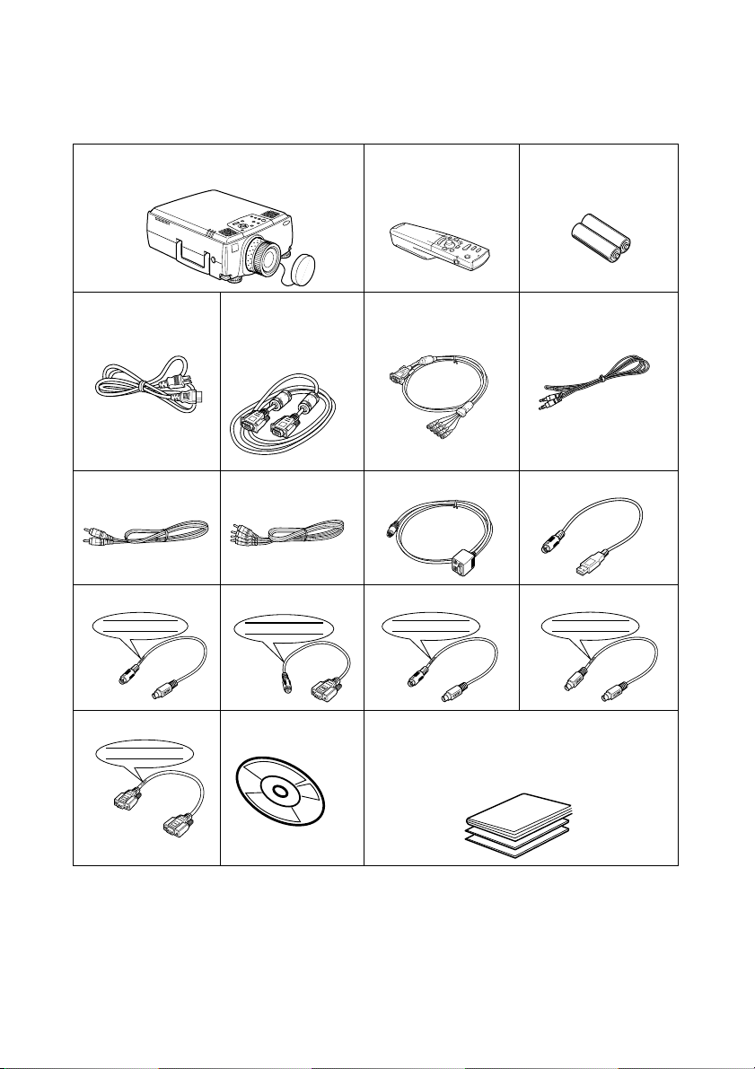
Accessory Verification
Check to confirm that the following items are included in the package when removing the projector and accessories from the box. Contact your dealer if any items are found to be missing.
·Projector
Lens cover with string
· Remote control · Two alkaline dry
cells for the remote
control
·Power cord ·Computer cable
(mini D-Sub
15-pin/mini
·Computer cable
(mini D-Sub
15-pin/5BNC)
·Audio cable
D-Sub 15-pin)
· RCA video cable
(Yellow)
· RCA audio cable
(Red/White)
· Main cable · USB mouse cable
· PS/2 mouse cable · Serial mouse cable · Mac mouse cable · Mac serial cable
PS/2 MOUSE
SERIAL MOUSE
E
S
U
O
M
L
A
I
R
E
S
MAC MOUSE
MAC SERIAL
· PC serial cable · Projector software
PC SERIAL
CD-ROM
· Safety Instructions/World-Wide Warranty
Te r ms
· Owner’s Manual (this document)
·Quick Reference Guide
Page 3
About the Manuals and Notations Used
Types of Manual
The documentation for your EPSON projector is divided into the following three manuals. The
manuals cover the following topics.
Safety Instructions/World-Wide Warranty Terms
This manual contains information on using the projector safely, and also includes WorldWide Warranty Terms and a troubleshooting check sheet.
Be sure to read this manual thoroughly before using the projector.
Owner’s Manual (this manual)
This Owner’s Manual contains information on installing the projector, basic operation,
using the projector menus, troubleshooting and maintenance.
Quick Reference Guide
Contains an overview of the most commonly-used projector functions for easy reference.
You should keep this Quick Reference Guide near the projector at all times and refer to it
before starting presentations and while using the projector in order to check details of
operation.
Symbol Displays
● Safety-related displays
A variety of picture displays have been used in this manual and on the actual product to ensure
that the projector is used correctly and safely in order to prevent risks to users and other people, and to prevent damage to property. Explanations for these displays are provided below.
Ensure that they are fully understood before reading this manual.
Wa rn i ng
Caution
Displays details that may result in death or injury if
ignored.
Displays details that may result in injury or damage to
property if ignored.
● General information
Point: Includes supplementary explanations and useful tips.
(see page xx) : Indicates reference pages
*: Indicates that an explanation of the word or words in front of this symbol appears in the
"Terminology." Refer to the "Terminology."(see page 88)
· Usage of the terms“this unit” and “this projector” in this manual
The terms “this unit” and “this projector” appear regularly in this manual, and these
terms also cover the accessories supplied with the projector and other optional products.
· The projection distances, illustrations and screen sizes apply to when the standard lens is
in use.
About the Manuals and Notations Used - 1
Page 4

Contents
About the Manuals and Notations Used 1
Types of Manual ...................................................................1
Symbol Displays ...................................................................1
Parts, Names and Operations 6
Projector ...............................................................................6
Remote Control .................................................................. 10
Range of Remote Control Operations ................................ 13
Inserting the Remote Control Batteries .............................. 14
Installation Procedure 15
Installation Example ........................................................... 15
Screen Size and Projection Distance ................................. 16
Projection Angles ...............................................................17
Connecting the projector to a computer 18
Eligible Computers ............................................................. 18
In the case of the mini D-Sub 15 pin .................................. 20
In the case of 5BNC
(when connected to the second computer) ........................ 22
In the case of DVI-D* .........................................................23
Sound Connection .............................................................24
Connecting External Monitors ............................................ 25
Connecting Up the Mouse (wireless mouse function) ........ 26
Connecting Video Equipment 28
In the case of composite image signals .............................28
In the case of S image signals ...........................................28
In the case of component
(color differential*) image signals ....................................... 29
In the case of RGB image signals ...................................... 30
Projection 31
Preparations .......................................................................31
Commencing Projection ..................................................... 32
2- Contents
Page 5

Ending 35
Adjusting the Projection Position 37
Feet Adjustments ............................................................... 37
Adjusting the projection size 38
Zoom Adjustment ............................................................... 38
Keystone Adjustment ......................................................... 38
Picture Quality Adjustment 39
Focus Adjustment .............................................................. 39
Auto Adjustment (when projecting computer images) .......39
Tracking Adjustments
(when projecting computer images) ................................... 40
Synchronization Adjustments
(when projecting computer images) ................................... 40
Calling Out Adjustment Values
(when projecting computer images) ................................... 40
Introduction of Functions 41
Useful Functions 42
Help Function ..................................................................... 42
Projection Cutting 44
A/V Mute Function .............................................................44
Freeze Function ................................................................. 44
Switching Image Sizes 45
Enlarging Images (E-Zooming function) 47
Contents- 3
Page 6

Effect Function 48
Cursor/Stamp .....................................................................48
Box .....................................................................................48
Spotlight .............................................................................49
Bar .....................................................................................50
Canceling Effects ...............................................................50
P in P Function 51
Volume Adjustment 52
Menu Configuration 53
Menu Items ........................................................................53
Menu Operations 55
Operation Method ..............................................................55
Setting Items ......................................................................57
User Logo Registration ......................................................62
Introduction of Projector Software 64
Outline of Projector Software .............................................64
Computer Connections 65
Serial Connections ............................................................. 65
Installation 67
Operating Environment ......................................................67
Installation ..........................................................................68
Reading the User’s Guide .................................................. 69
Troubleshooting 70
Operation Indicator .............................................................70
Lamp Indicator ...................................................................71
Temperature Indicator ........................................................ 72
4- Contents
Page 7

When the Indicators Provide No Help 73
The image is not projected ................................................. 73
The image is unclear .......................................................... 75
The image is cut up (Large)/Small ..................................... 77
The image color is bad ....................................................... 77
The image is dark ..............................................................78
No sound ............................................................................ 78
The remote control won’t work ........................................... 79
Cannot end (after the [Power] button has been pressed) .. 79
EMP Link V will not function ............................................... 80
Cleaning the Projector, Cleaning the Lens,
Cleaning the Air Filter 81
Cleaning the Projector .......................................................81
Cleaning the Lens .............................................................. 81
Cleaning the Air Filter ........................................................82
Replacing the Air Filter 83
Replacement Method ......................................................... 83
Replacing the Lamp 84
Replacement Method ......................................................... 85
Resetting the Lamp Illumination Time ................................ 86
Optional Parts 87
Terminology 88
Specifications 90
Index 92
Contents- 5
Page 8
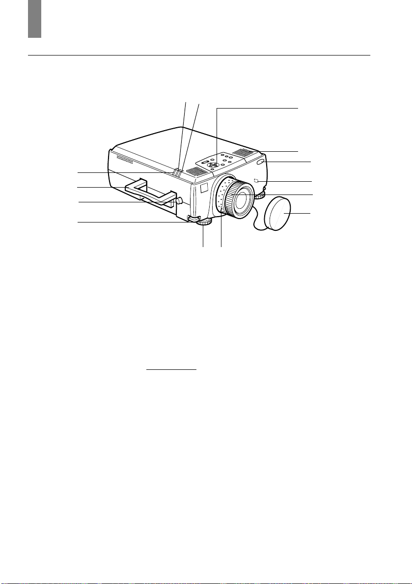
Parts, Names and Operations
Projector
● Front Panel
1
2
3
4
5
6
1214
1 Lamp indicator
2 Operation indicator
3 Temperature indicator
4 Handle
5 Lens shift knob
6 Foot adjust lever
7 Operation panel
8 Speaker
9 Remote control light-receiving area
10 Theft-protection lock (see page 88
11 Focus ring
12 Zoom ring
13 Lens cover
14 Front foot
)
7
8
9
10
11
13
6 - Parts, Names and Operations
Page 9
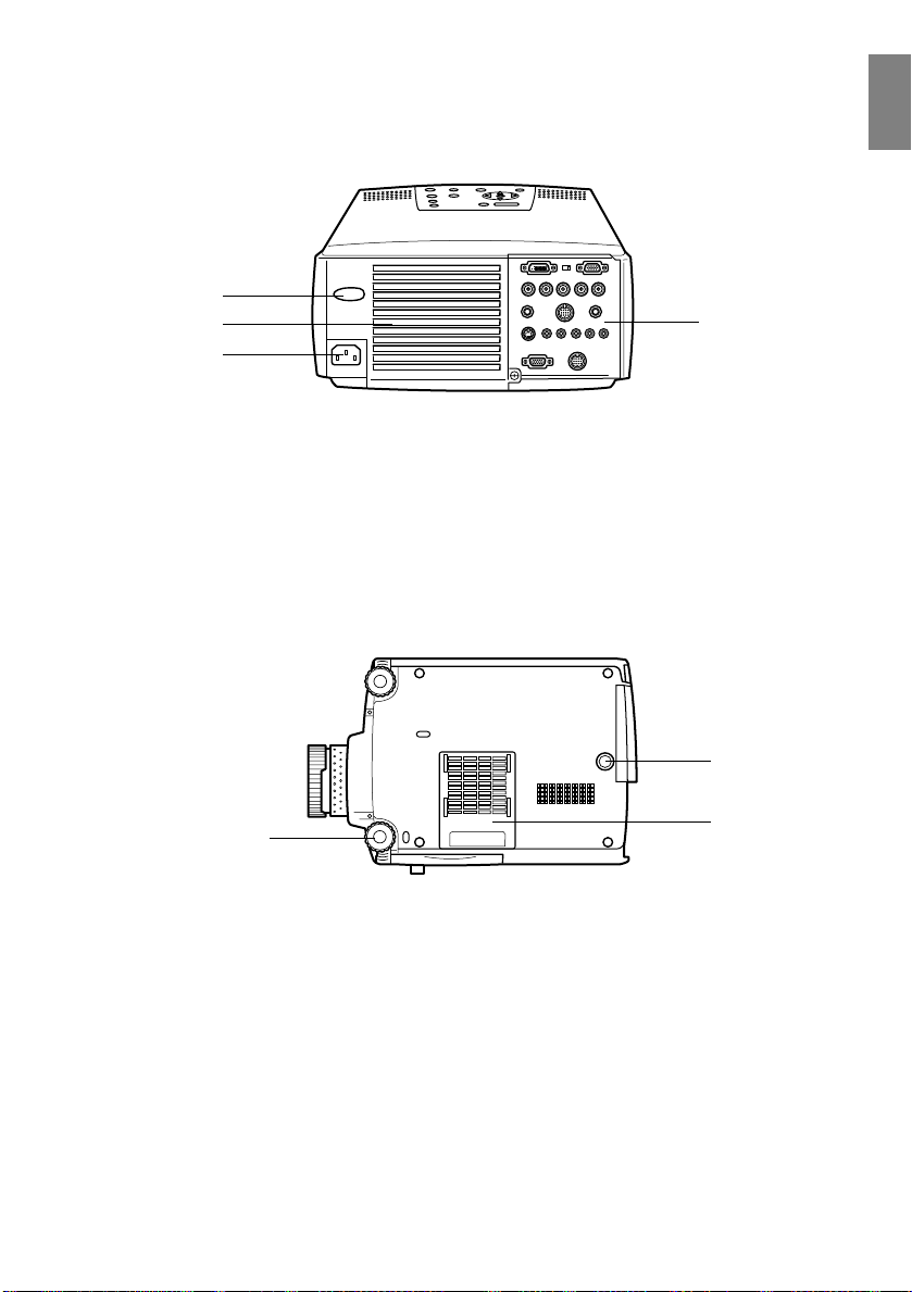
● Back Panel
1
2
3
1 Remote control light-receiving area
2 Fan
3 Power inlet
4 I/O port
● Rear Panel
4
1
1 Front foot
2 Rear foot
3 Air filter (suction inlet)
2
3
Parts, Names and Operations - 7
Page 10
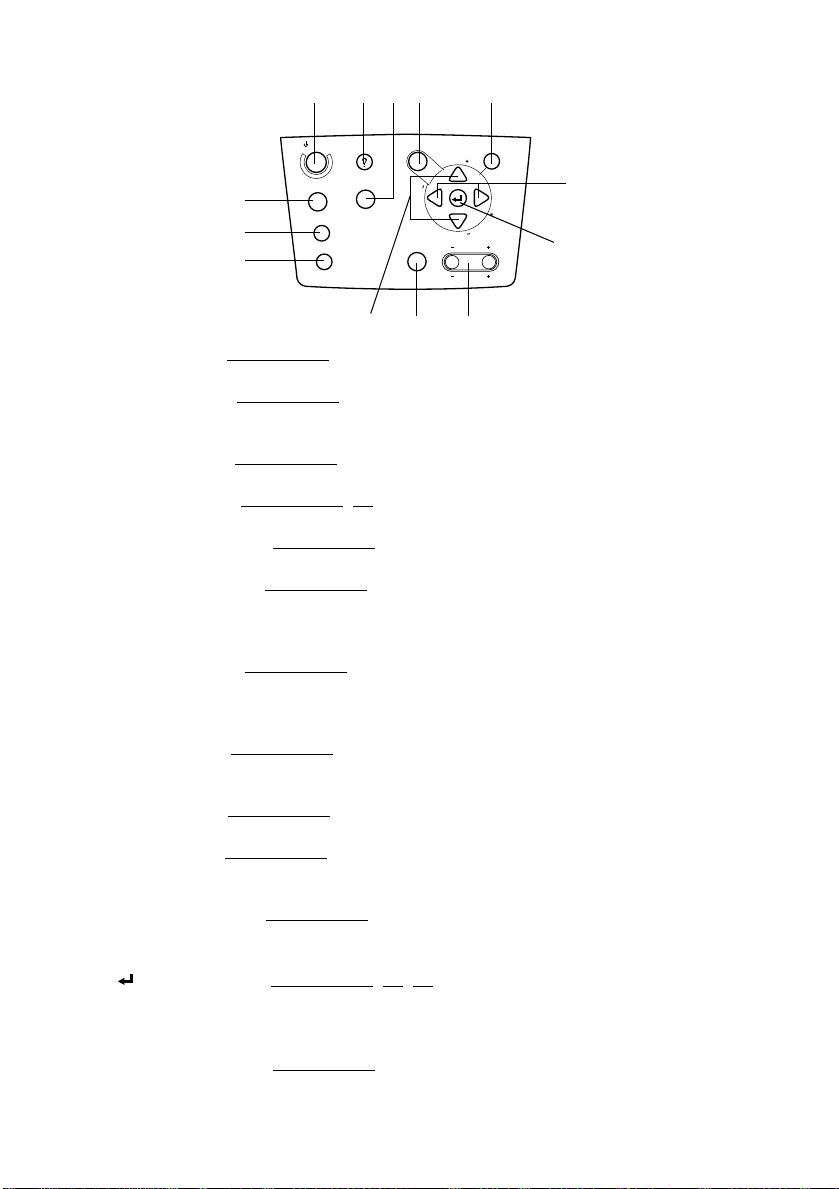
● Operation Panel
4123 10
Power
Computer
5
6
7
A/V mute
Resize
Help
Video
Menu
g
n
i
k
c
a
r
Shift
8
9
Esc
n
c
y
.
S
T
r
a
c
k
i
n
S
y
.
c
n
Keystone
Volume
g
T
11
12
13
1 [Help] button (see page 42)
Displays the methods of solving problems. Press this button when trouble occurs.
2 [Video] button (see page 33)
Switches the images between video images (Video), S video (S-Video) and component
video (BNC (YCbCr, YPbPr)).
3 [Menu] button (see page 55)
Displays and cancels the menu.
4 [Power] button (see page 32, 35 )
Switches the power supply on and off.
5 [Computer] button (see page 33)
Switches images between the Computer 1 image and BNC (RGB).
6 [A/V Mute] button (see page 44)
Temporarily erases the image and sound. Projection is resumed when this button is pressed
once more or when the volume control is adjusted or when the menu is displayed. A user
logo can also be set up for projection when in the mute mode.
7 [Resize] button (see page 45)
Switches between the window display and the resizing display when computer images are
being projected. Switches the aspect ratio between 4:3 and 16:9 when video images are
being projected.
8 [Sync] button (see page 40)
Makes the necessary adjustments when the screen is out of focus or flickering. This button
functions as the up and down key when the menu or help text is being displayed.
9 [Shift] button (see page 52)
Adjusts the volume when pressed simultaneously with the [Volume (Keystone)] button.
10 [Esc] button (see page 56)
Ends functions that are currently in use. Returns the screen to the previous stage when this
is pressed during menu and help text display.
11 [Tracking] button (see page 40)
Performs the necessary adjustments when stripes appear on the screen. Moves left and
right when this is pressed during menu and help text display.
12 [ (Enter)] button (see page 39, 42, 55)
· Sets the menu item and moves onto the lower stage.
· Optimizes the computer image when the menu or help text is not displayed.
(Switches the input resolution across to [Auto] when set for [Manual]).
13 [Keystone] button (see page 38)
Performs the necessary adjustments when the screen distorts into a trapezoid shape.
8 - Parts, Names and Operations
Page 11
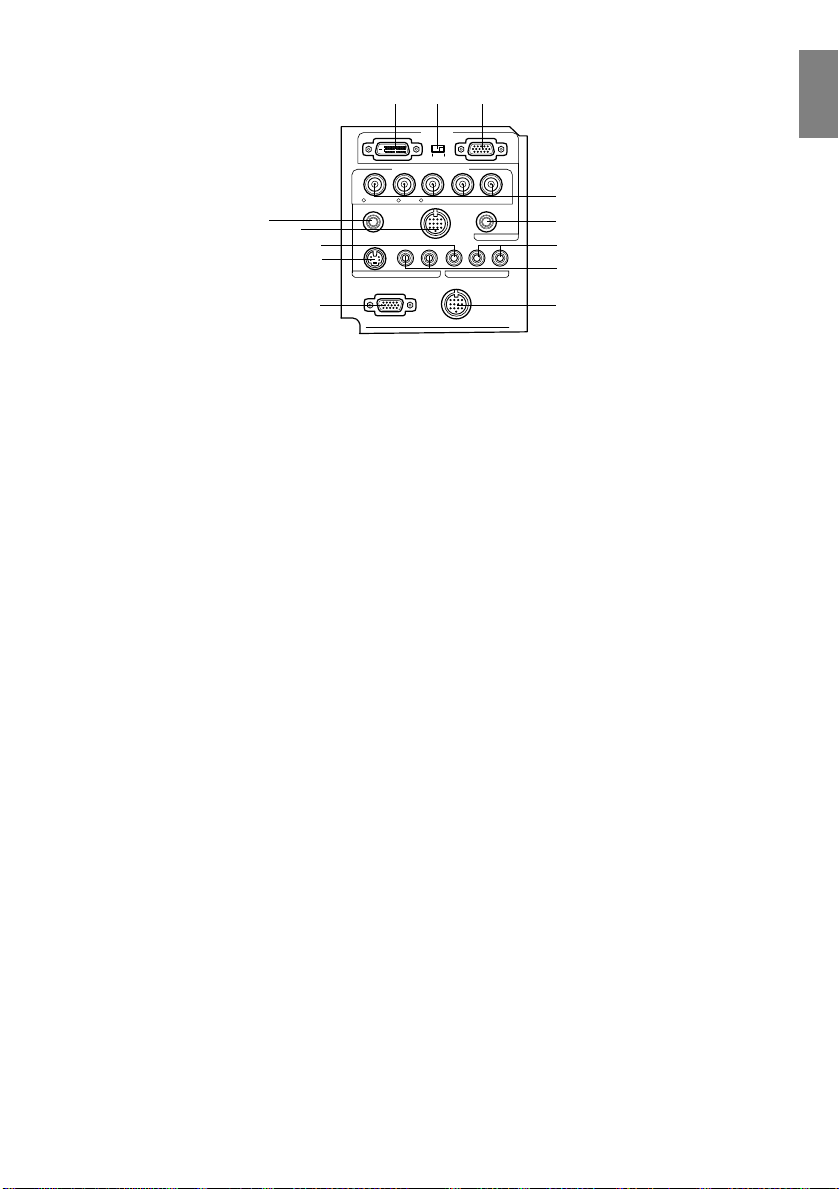
● I/O Ports
3
21
Computer 1
Component Video
Computer 2 /
R/Cr/Pr
B/Cb/Pb H/C Sync V SyncG/Y
5
6
Remote
10
8
S-Video S-Audio/Audio2 L-Audio-RVideo
12
Monitor Out
Mouse/Com
Audio
Stack Out
1 Computer 1-mini D-Sub 15 port
Inputs the computer’s analog image signals.
2 Change-over switch
Switches the valid port for Computer 1 across to either mini D-Sub15 (analog) or DVI-D
(digital). Operate the switch with the tip of a ballpoint pen or other pointed object.
3 Computer 1-DVI-D port
Inputs the computer’s digital image signals.
4 Computer 2-BNC port
· R/Cr/Pr · G/Y · B/Cb/Pb · H/C Sync · V Sync
Inputs the computer’s BNC image signals, the A/V equipment’s component image signals
(color differential signal*) or the RGB image signals.
5 Remote port
Connects the optional remote control receiver (ELPST04).
6 Mouse/Com port
Establishes a connection with the computer when the projector software that is supplied is
to be used or when the remote control is used as a wireless mouse.
7 Audio port
Inputs the audio signals from the computer and A/V equipment connected to the
Computer 1 port.
8 S-Video port
Inputs the A/V equipment's S image signals.
9 S-Audio/Audio 2 port
Inputs the audio signals from the computer and A/V equipment connected to the BNC
port or the S-Video port.
Outputs only the sound for connected computers and A/V equipment.
10 Video port
Inputs the the A/V equipment’s component image signals.
11 L-Audio-R port
Inputs the the A/V equipment’s sound signals.
12 Monitor Out port
Outputs the projected image signals to an external monitor (not output when the input
comes from the DVI-D port.)
13 Stack Out port
This is used during stack projection*.
4
7
11
9
13
Parts, Names and Operations - 9
Page 12
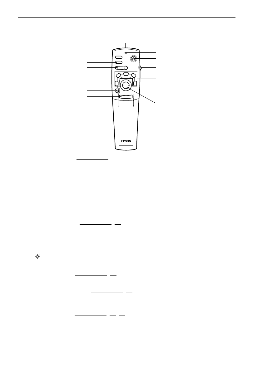
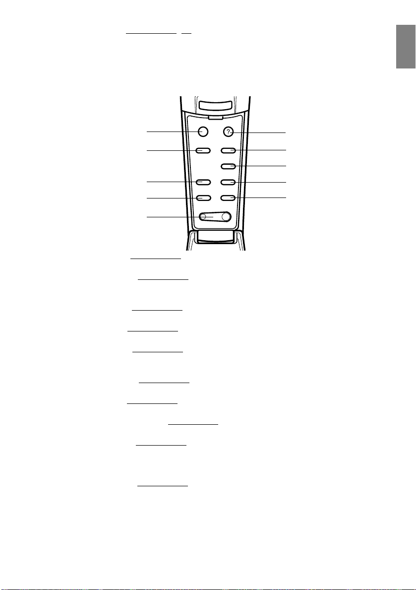
Remote Control
● Front Panel
2
Power
1
4
5
Freeze
A/V Mute
E-Zoom
2
1
R/C ON
OFF
3
4
5
Enter
7
11
Esc
1 [Freeze] button (see page 44)
Temporarily freezes the image. Press this button once more to cancel the freeze mode.
2 Remote control light-emitting area
Outputs the remote control signals.
3 Indicator
Illuminated when the remote control signals are being output.
4 [A/V Mute] button (see page 44)
Temporarily erases the images and sound. Projection will be resumed if this button is
pressed once more or the volume is adjusted. A user logo can be set up for projection when
in the mute mode.
5 [E-Zoom] button (see page 47, 51)
Enlarges the image with the E-Zoom function. Enlarges the sub-screen when using P in P
images. Press the [Esc] key to cancel this mode.
6 [Effect] button (see page 48)
Executes the allocated effect function. Press the [Esc] key to cancel this mode.
7 [ (Light)] button
The remote control buttons will be illuminated for approximately ten seconds.
8 [Power] button (see page 32, 35)
Switches the power supply to the projector on and off.
9 [R/C ON OFF] switch (see page 32, 36)
Switches the remote control on and off. The remote control cannot be used for operations
when this switch is not set at [ON].
10 [Enter] button (see page 27, 42, 55)
· Sets the menu item when pressed, and then moves onto the lower stage. Becomes a cursor key to select the menu items when moved up, down, left or right.
· This function operates as a left-hand click on the mouse when computer images are being
projected. The pointer will move when this button is moved up, down, left or right.
3
8
9
6
10
10 - Parts, Names and Operations
Page 13
11 [Esc] button (see page 27, 56)
· Ends the function being used. Returns to the previous stage when the menu or help text is
being displayed.
· This function operates as a right-hand click on the mouse when computer images are
being projected.
Inside of the Cover
●
Esc
Help
1
2
4
5
6
Menu
Comp2/YCbCr
Comp1
E@sy-MP
Auto
P in P Preset
- Volume +
Video
Resize
7
8
3
9
10
1 [Menu] button (see page 55)
Displays and ends the menu.
2 [Comp1] button (see page 33)
Switches across to the image from Computer 1 port. (Switches across to the DVI-D image
when the switch is set at the left-hand side.)
3 [Video] button (see page 33)
Switches between video images (Video) and S-video images (S-Video).
4 [Auto] button (see page 39)
Optimizes the computer image.
5 [P in P] button (see page 51)
Displays the video image within the computer image or the video image as a sub-screen.
This function is cancelled by pressing this button once again.
6 [Volume] button (see page 52)
Adjusts the volume.
7 [Help] button (see page 42)
Displays the method of solving problems. Press this button when trouble occurs.
8 [Comp2/YCbCr] button (see page 33)
Switches between the images from the BNC port.
9 [Resize] button (see page 45)
Switches between the window display and the resizing display when computer images are
being projected. Switches the aspect ratio between 4:3 and 16:9 when video images are
being projected.
10 [Preset] button (see page 40)
Calls out the preset computer input settings.
Parts, Names and Operations - 11
Page 14
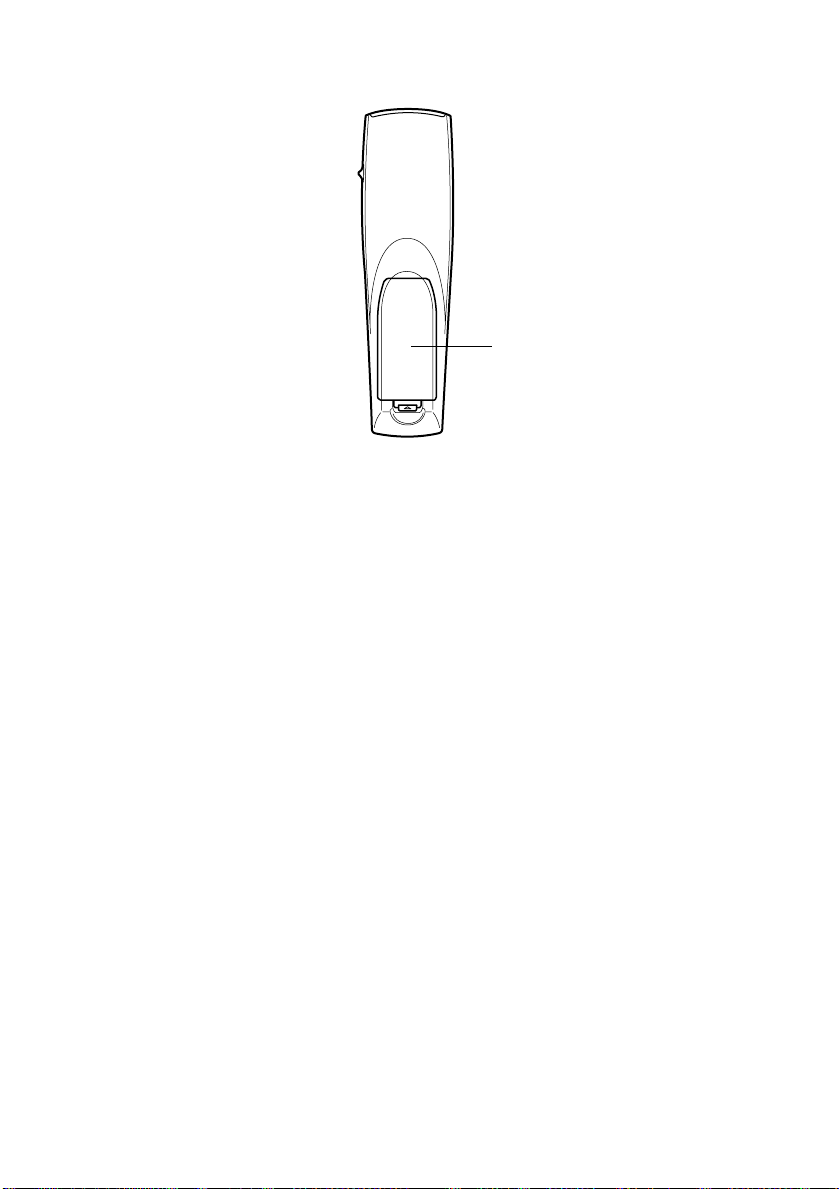
● Rear Panel
1 Battery cover
1
12 - Parts, Names and Operations
Page 15
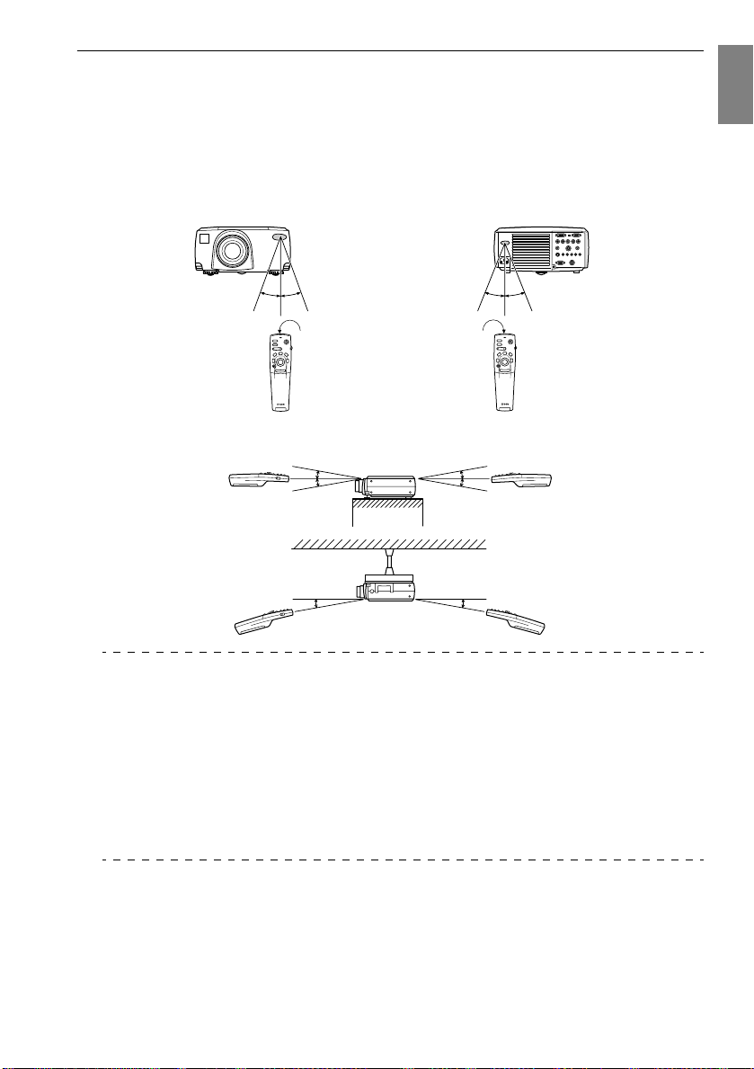
Range of Remote Control Operations
Depending on the distance and angle from the main unit’s light receiving area, there are cases
where the remote control will not function. Ensure that the remote control is used within the following conditions:
● Operable distance: Approximately 10 meters
● Operable range:
(Front Panel)
Rear Panel)
(
Approximately 30
degrees
Approximately 15
degrees
Approximately 15
degrees
Light-emitting area on
the remote control
Approximately 15
degrees
Approximately 15
degrees
Approximately 30
degrees
Point
· Ensure that the [R/C ON OFF] switch is set at [ON] when using the remote control.
· Aim the remote control at the projector’s light-receiving area.
· There are cases where the operable distance (approximately 10 meters) of the remote
control is diminished when signals are reflected off screens depending on the type of
screen in use.
· Ensure that sunlight and florescent lighting is not shone directly into the projector’s lightreceiving area.
· If the remote control will not function or malfunctions, there is a possibility that the batteries need changing. In this event, replace the batteries accordingly.
· Use the optional remote control receiver if it is to be used at a distance of 10m or more.
Parts, Names and Operations - 13
Page 16
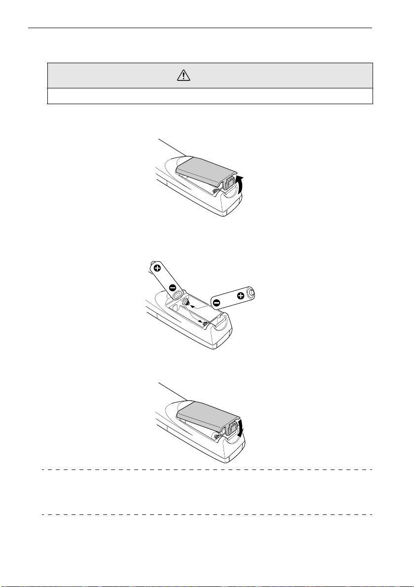
Inserting the Remote Control Batteries
The remote control batteries are inserted in accordance with the following procedure:
Caution
Ensure that unused batteries of the same type are used.
Remove the battery cover.
1
Apply pressure to the clip holding the battery cover, and then lift it upwards.
Insert the batteries.
2
Ensure that the batteries are aligned correctly with the “+” and “-“ labels on the remote
control.
Replace the cover.
3
Apply pressure to the battery cover until it clicks firmly into place.
Point
· Specified batteries: Two alkaline dry cells LR6 (AA).
· The batteries should be replaced approximately once every three months when used for
thirty minutes per day.
14 - Parts, Names and Operations
Page 17
Installation Procedure
Determines the projection angle and projection distance to ensure the most suitable screen
display.
Caution
· Do not block the ventilation outlet at the back of the projector or the air filter (suction inlet)
on the rear panel.
· There are cases where material or paper get sucked onto the air filter on the rear panel
when the projector is in use, so attention must be paid to prevent this.
· Do not place the projector in a location where it is subject to the direct air flow from air conditioners or heaters.
· When the projector is to be placed near a wall, ensure that there is at least 20cm of space
between the wall and the projector.
· Do not cover the projector with table cloths or other material.
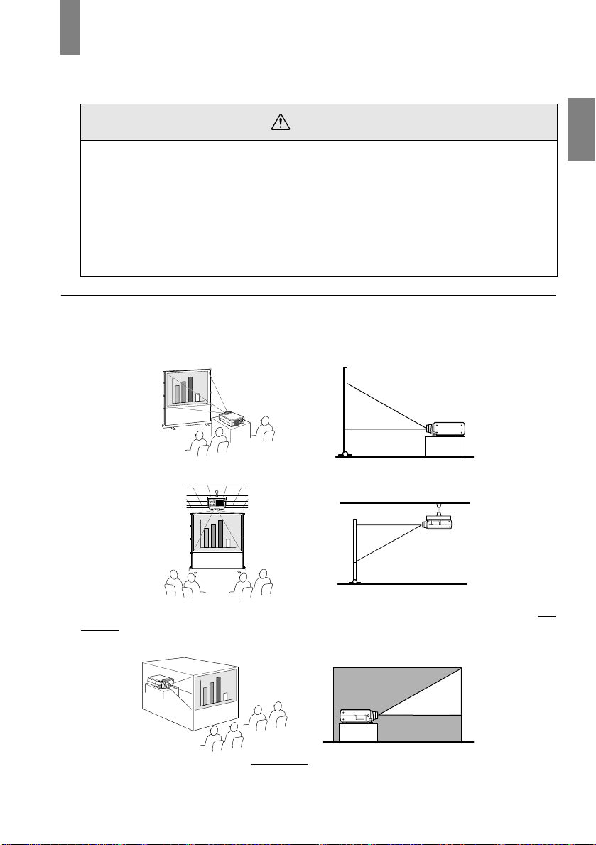
Installation Example
The projector may be installed in locations that conform to the installation conditions and projection methods.
Viewing projected images from the front
Viewing projected images from the front with a ceiling suspended projector
Use the optional ceiling suspension unit and set the ceiling suspension parameter to [ON]. (see
page 61)
Viewing images projected onto half-transparent screens from the rear
· Set the rear parameter to [ON]. (see page 61)
· Ceiling suspension is also possible with the use of the optional ceiling suspension unit.
Installation Procedure - 15
Page 18
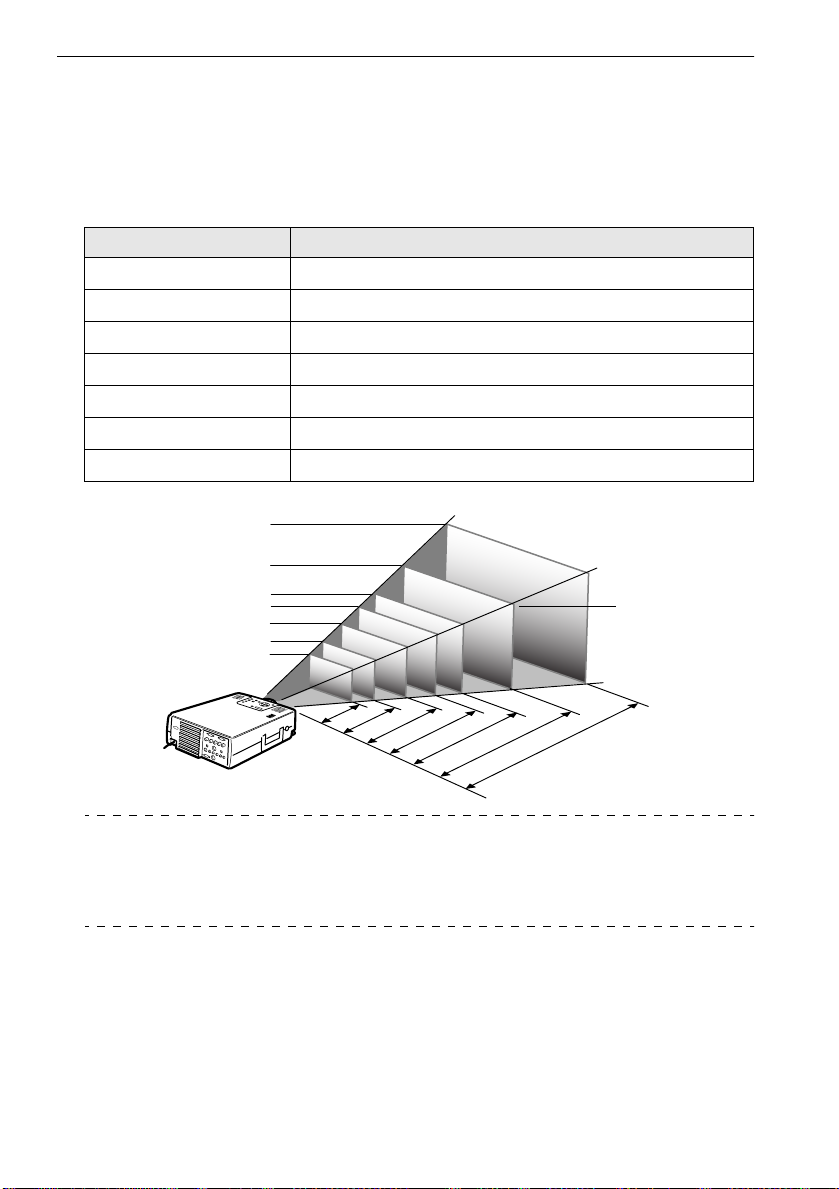
Screen Size and Projection Distance
Determines the distance that the screen must be from the lens in order to obtain the required
screen size.
The projector’s standard lens is approximately a 1.3x zoom lens and the largest screen size is
about 1.3 times the size of the smallest screen.
Using the following table for reference purposes, install the projector so that the screen size is
smaller than the screen.
Screen Size Approximate Projection Distance
30-inch (61
40-inch (81
60-inch (120
80-inch (160
100-inch (200
200-inch (410
300-inch (610
×
46cm)
×
61cm)
×
90cm)
×
120cm)
×
150cm)
×
300cm)
×
460cm)
1.1m to 1.4m (3.6ft. to 4.6ft.)
1.5m to 1.8m (4.8ft. to 6.2ft.)
2.3m to 2.8m (7.3ft. to 9.4ft.)
3.0m to 3.8m (9.8ft. to 12.6ft.)
3.8m to 4.8m (12.3ft. to 15.8ft.)
7.6m to 9.7m (24.8ft. to 31.9ft.)
11.4m to 14.6m (37.3ft. to 48.1ft.)
Screen Size
300-inch
200-inch
100-inch
80-inch
60-inch
40-inch
30-inch
81X61 cm
61X46 cm
160X120 cm
120X90 cm
1.1 - 1.4 m
(3.6 - 4.6)
1.5 - 1.8 m
410X300 cm
200X150 cm
6.2)
-
(4.8
(7.3
2.3 - 2.8 m
3.0 - 3.8 m
9.4)
(9.8
3.8 - 4.8 m
-
12.6)
610X460 cm
15.8)
-
(12.3
7.6 - 9.7 m
11.4 - 14.6 m
Center of the lens
31.9)
-
(24.8
)
(37.3 - 48.1 ft.
Distance from the projector
Point
· The projection distances listed above are the distances when the standard lens is in use.
If optional lenses are to be used, refer to the relevant instruction manuals for further
details.
· The screen size will become smaller when the trapezoid correction function is used.
16 - Installation Procedure
Page 19
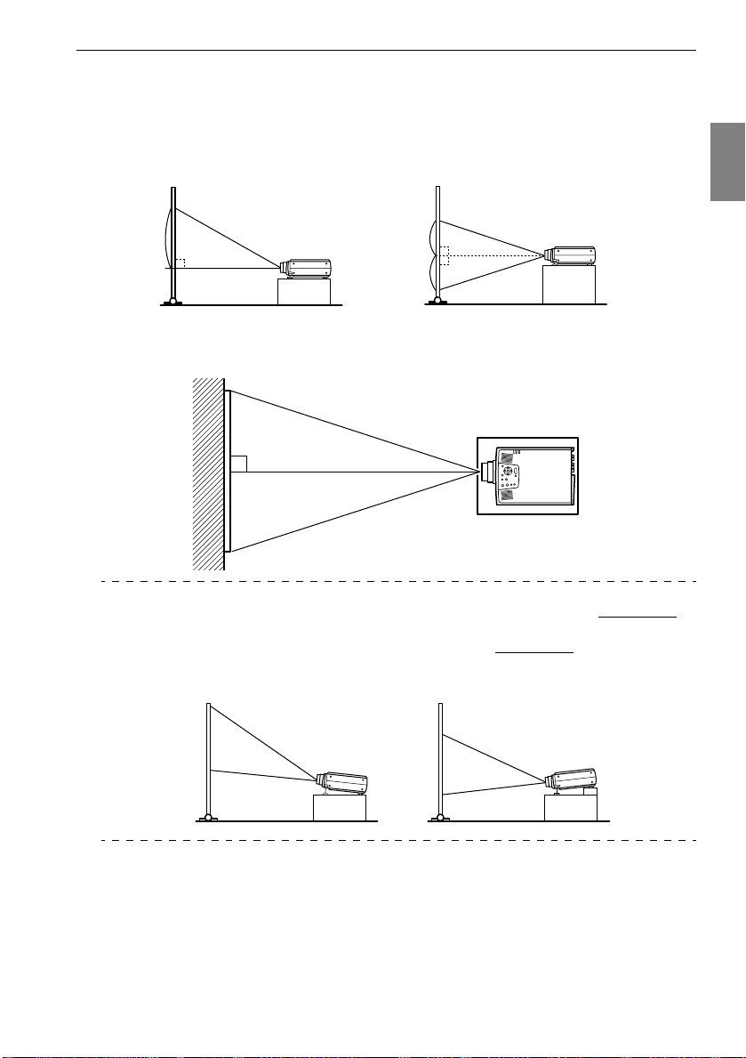
Projection Angles
Placing the projector with the center of the lens at an exact right-angle to the screen will provide optimal screen projection. Pay attention to the angle of projection when placing the projector inposition.
When viewing from the side
** The projection position can be moved up and down by turning the lens shift knob.
A
B
A:B 10:Becomes 0
A
B
A:B 5:Becomes 5
When viewing from the top or bottom
Point
Although the projection position can be adjusted with the foot adjust lever (see page 37),
there are cases where the screen will distort into a trapezoid shape. In this event, adjust the
trapezoid distortion with the trapezoid correction function. (see page 38
)
Upward 30°
Downward 30°
Installation Procedure - 17
Page 20
Connecting the projector to a computer
Switch off the power supply to the projector and computer before attempting to make the
connection.
Eligible Computers
There are computers with which connections cannot be established and computers that cannot
be used for projection purposes even though a connection has been established. First of all, it is
necessary to confirm that a connection can be established with the computer in use.
● Conditions for eligible computers
Condition #1: The computer must be fitted with an image signal output port
Check to ascertain that the computer is fitted with ports that will output image signals,
such as the "RGB Port", the "Monitor Port" and the "Video Port". If you have trouble
confirming this, refer to chapter on external monitor connections in the computer’s
instruction manual.
There are computers, such as combined computer/monitor models and laptop models,
that do not allow connections or for which optional external output ports must be
purchased.
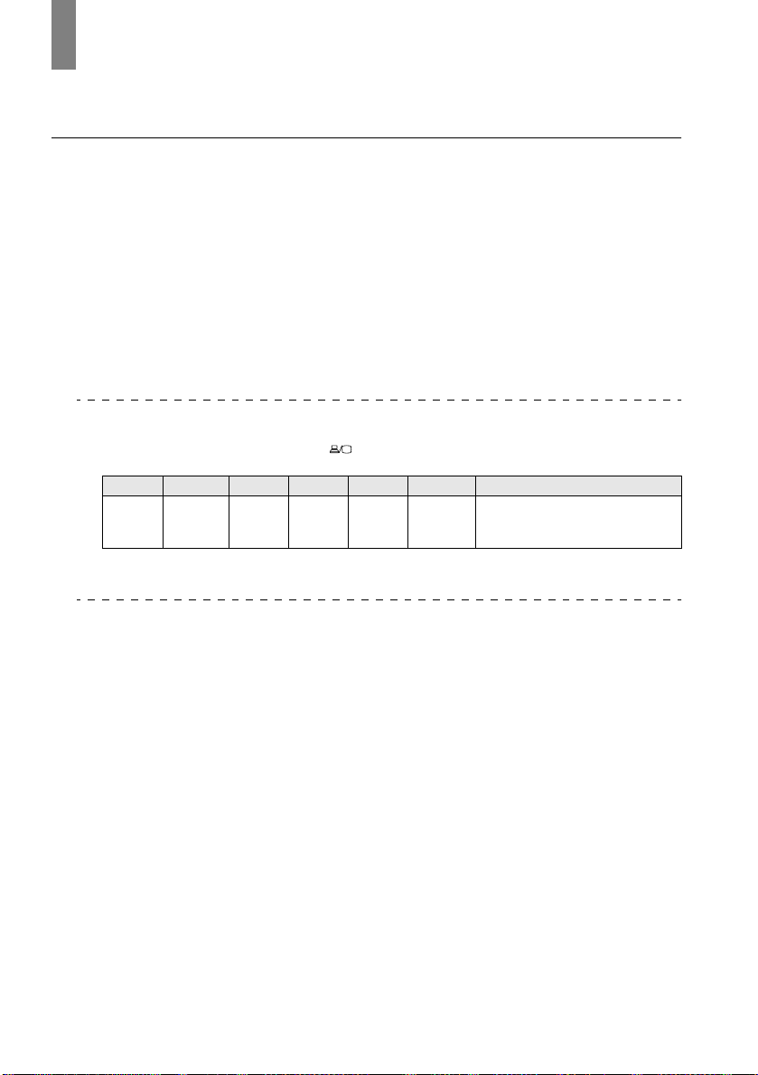
Point
Depending on the computer, there are cases when it is necessary to switch the image signal output with the connection key ( , etc.,) and the settings.
NEC Panasonic To sh i b a IBM SONY FUJITSU Macintosh
[Fn]+[F3] [Fn]+[F3] [Fn]+[F5] [Fn]+[F7] [Fn]+[F7] [Fn]+[F10] The control panel monitor and
The table shown above provides examples for certain products. Refer to the computer’s
instruction manual for further details.
sound to be set to mirroring after
rebooting.
Condition #2: The resolution and frequency of the computer must be within the
boundaries listed in the chart on the next page.
Projection will not be possible if the computer does not support the output image signal
resolutions and frequencies shown in the chart on the next page (there are cases where
projection is possible, but vivid projection will not be possible).
Confirm the image signal resolution and frequency with the computer’s instruction
manual.
There are also computers available that allow the output resolution to be amended. In this
case, amend the parameters to fit within the ranges shown in the chart on the next page.
18 - Connecting the projector to a computer
Page 21

Signal
PC98
VGACGA
VGAEGA
VGA 60
VESA 72/75/85/
SVGA 56/60/72/75/
XGA 43i/60/70/75/
SXGA 70/75/85
SXGA 60/75/85
SXGA 43i/60/75/85
SXGA+
UXGA 48i/60/65/70/
MAC13
MAC16
MAC19
MAC21
iMAC
NTSC
PA L
SECAM
SDTV
(525i)
HDTV
(750P)
HDTV
(1125i)
Refresh Rate
(Hz)
100/120
85/100/120
85/100
75/80/85
60
60
60
Pixels (dots)
Resolution
(Dots)
640
×
640
×
640
×
640
×
×
640
×
800
1024
115 2
1280
1280
×
1400
×
1440
×
×
1600
640
×
832
×
1024
115 2
640
×
800
×
1024
Used During
Resizing Dis-
play (Resize
On)
400 1024×640 640×400
400 1024×640 640× 400
350 1024×560 640×350
480 1024×768 640× 480
480 1024×768 640×480
600 1024×768 800×600
768 1024×768 1024× 768
×
864 1024×768 11 52× 864
×
960 1024×768 1280×960
×
1024 960×768 1280×1024
1050 996×746 1400×1050
1080 1024×768 1440×1080
1200 1024×768 1600×1200
480 1024×768 640×480
624 1024×768 832×624
768 1024×768 1024×768
×
870 1016×768 115 2×870
×
480 1024×768 640×480
600 1024×768 800×600
768 1024×768 1024×768
×
1024
768 1024×576 4:3
×
1024
768 1024×576 4:3
×
1024
768 1024×576 4:3
×
1024
768
×
(4 : 3)
Pixels (dots)
Used During
Real Display
(Resize Off)
1024
576
×
(16 : 9)
1024
576
×
(16 : 9)
1024
576
×
(16 : 9)
Remarks
Virtual (Partial) Display
Virtual (Partial) Display
Virtual (Partial) Display
Virtual (Partial) Display
Virtual (Partial) Display
Virtual (Partial) Display
16:9, Selectable
↔
16:9, Selectable
↔
16:9, Selectable
↔
Connecting the projector to a computer - 19
Page 22
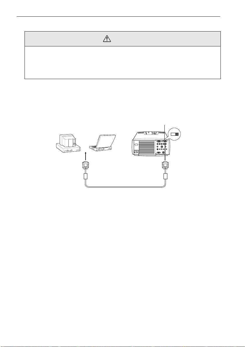
In the case of the mini D-Sub 15 pin
Caution
· Switch off the power supply to the projector and computer before attempting to make the
connection. Failure to observe this may result in damage.
· Confirm the shape of the cable connector and the shape of the port before making the connection. Applying excessive force when the direction or shape of the connector and port
differ may result in defects and damage to the equipment.
· Connect the computer’s monitor port to the Computer 1-mini D-Sub 15 port on the projector
with the computer cable supplied.
· Set the switch to the analog setting (right-hand side) with the tip of a ballpoint pen or other
pointed object.
● When the monitor port is the mini D-Sub 15 pin
Computer 1-mini D-Sub15 port
Monitor port
(video port)
Computer cable
(supplied with the projector)
20 - Connecting the projector to a computer
Page 23
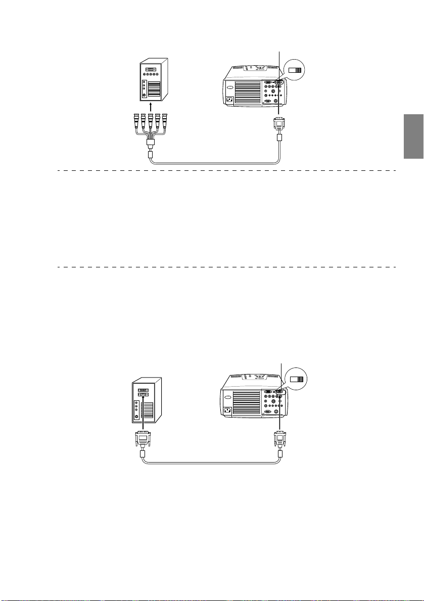
● When the monitor port is the 5BNC
Computer 1-mini D-Sub15 port
Monitor port
(video port)
Computer cable
(supplied with the projector)
Point
· Do not bind the power cable and the computer cable together. Failure to observe this may
result in malfunctions.
· An adapter may be required when making the connection depending on the shape of the
computer’s port. Refer to the computer instruction manual for further details.
· There are cases where the optional Mac desktop adapter and Mac monitor adapter are
required when connecting up to a Macintosh.
· It is possible to establish connections with both the Computer 1 port and the Computer 2
port when two computers are to be connected.
● When the monitor port is 13w3
The Computer 1 port is also connected to the mini D-Sub 15 port with the use of the conversion
cable when the 13w3 port is used for connecting the computer’s monitor port to a work station.
· The projector’s computer 1-mini D-Sub 15 port is connected to the computer ’s monitor port
(13w3) with the 13w3 ↔ mini D-Sub 15 cable (available on the open market).
· Set the switch to the analog setting (right-hand side) with the tip of a ballpoint pen or other
pointed object.
Monitor port
Computer 1-mini D-Sub15 port
(available on the open market)
13w3 cable
Connecting the projector to a computer - 21
Page 24
In the case of 5BNC (when connected to the second computer)
Connects the computer’s monitor port to the projector’s Computer 2-BNC port with the computer cable supplied.
Computer 2-BNC port
Monitor port
Computer cable
(supplied with the projector)
Point
· Set the BNC parameter to [RGB] when establishing the connection. (see page 59)
· Make the connection with the 5BNC ↔ 5BNC cable (available on the open market) when
the computer’s monitor port is 5BNC.
· Connections can be made to both computer 1 port and computer 2 port when two com-
puters are to be connected.
22 - Connecting the projector to a computer
Connection with the first computer
Connection with the second computer
Page 25
In the case of DVI-D*
Digital signals are output to the projector without amendment if the computer has a standard
DVI-compliant digital video card or video output port.
· Connect the computer's digital output port to the projector's computer 1-DVI-D port with the
optional digital video cable. Select the cable in accordance with the shape of the computer’s
port (DVI-D/DFP).
· Set the switch to the digital setting (left-hand side) with the tip of a ballpoint pen or other
pointed object.
Monitor port
Digital video cable
(optional)
Point
There are cases where the computer must be set up in order to switch the computer output
to the DVI-D. Refer to the instruction manual for the computer for further details.
Computer 1-DVI-D port
Connecting the projector to a computer - 23
Page 26
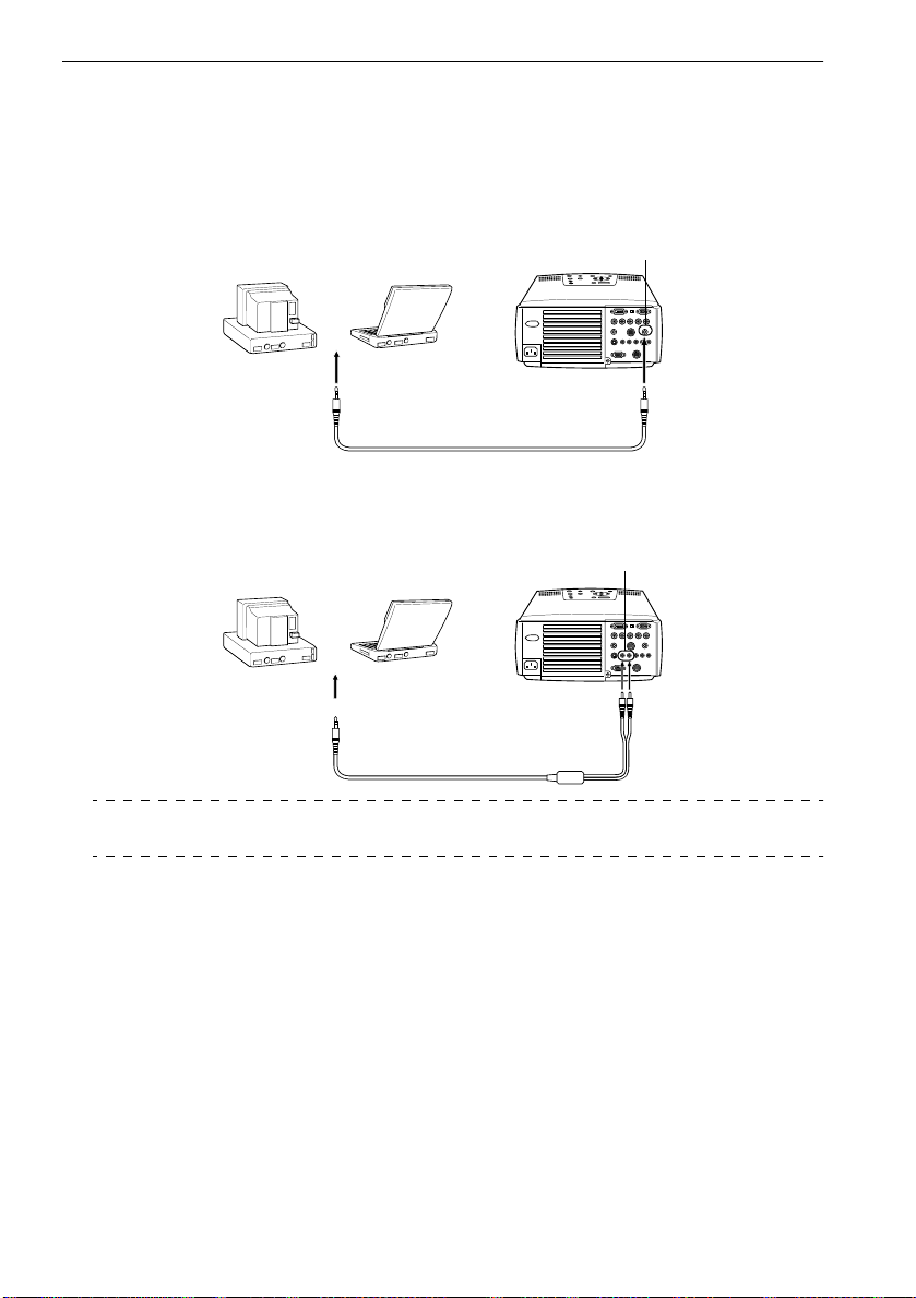
Sound Connection
The projector is equipped with two built-in speakers capable of outputing a maximum of 3W,
and it is also possible to output computer sound from the projector’s speakers.
● Connecting the computer to Computer 1
Connect the projector’s Audio port (stereo mini jack) to the computer ’s audio output port with
the audio cable supplied.
Computer’s audio output port
Audio cable
(supplied with the projector)
Audio port
● Connecting the computer to Computer 2
Connect the computer's audio output port to the projector's S-Audio/Audio 2 port (RCA pin
jack) with the RCA audio cable (sold on the open market).
Computer’s audio output port
RCA audio cable
(available on the open market)
Point
The audio signals output the selected image’s sound.
S-Audio/Audio 2 port
24 - Connecting the projector to a computer
Page 27
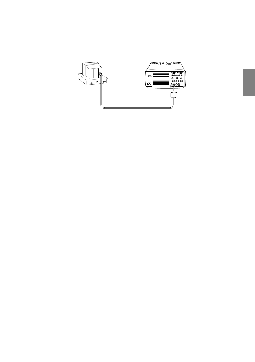
Connecting External Monitors
It is possible to display the image projected with the projector onto a computer simultaneously.
Connect the projector's monitor out port to the computer monitor with the cable attached to the
monitor.
Monitor Out port
Cable attached to the monitor
Point
· There are cases where the optional Mac desktop adapter and Mac monitor adapter are
required when connecting up to a Macintosh.
· Images cannot be displayed on external monitors when the computer is connected to the
DVI-D port.
Connecting the projector to a computer - 25
Page 28
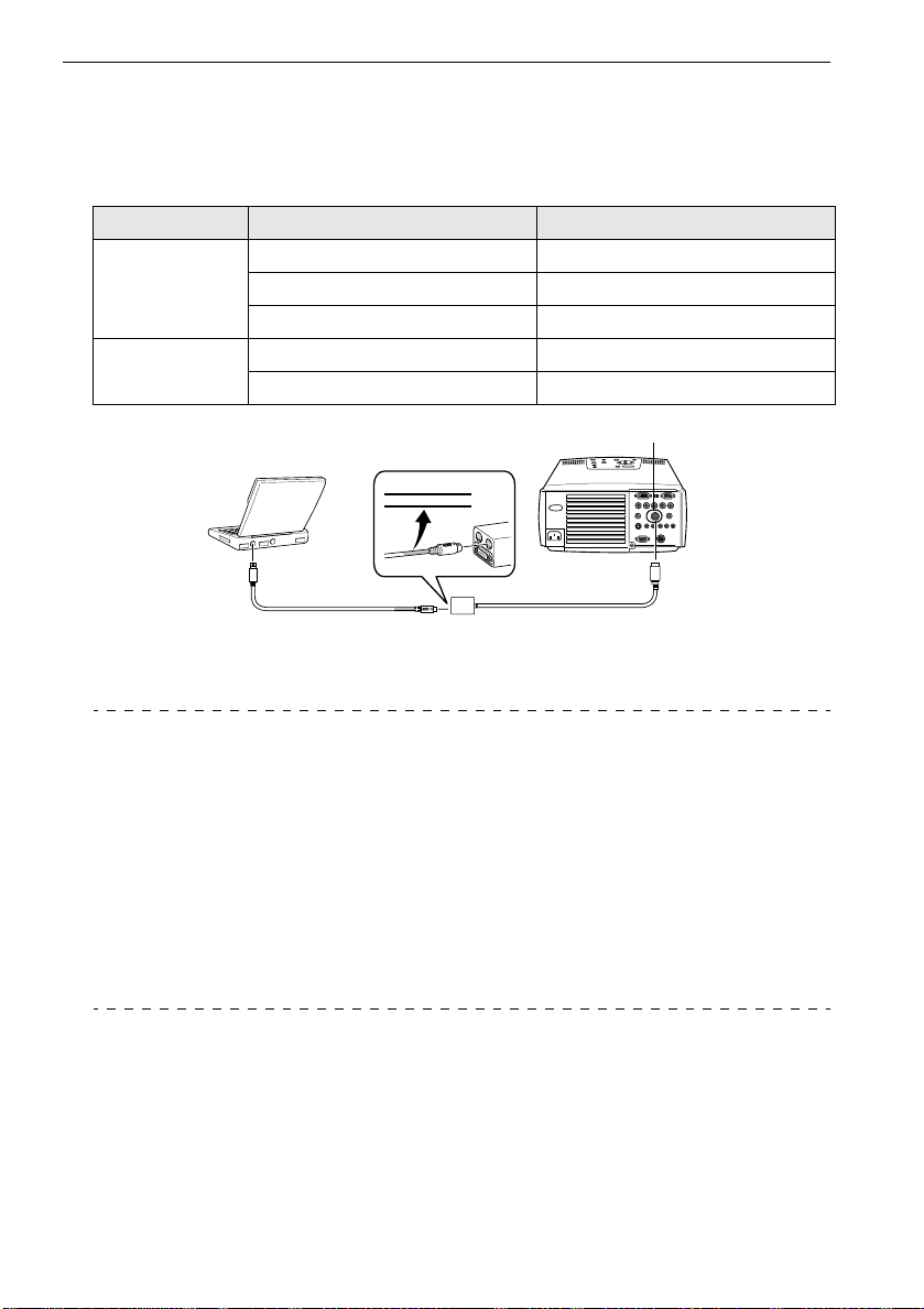
Connecting Up the Mouse (wireless mouse function)
This enables the computer’s mouse pointer to be operated with the remote control in the same
way as a wireless mouse.
Connect the projector’s Mouse/Com port to the computer ’s mouse port with the mouse cable
and main cable.
Computer Mouse to use Mouse cable to use
PC/AT
DOS/V
Macintosh Macintosh mouse Mac mouse cable (supplied)
PS/2 mouse PS/2 mouse cable (supplied)
Serial mouse Serial mouse cable (supplied)
USB mouse USB mouse cable (supplied)
USB mouse USB mouse cable (supplied)
PS/2 connection
Mouse cable
Mouse port
Mouse cable
(supplied with the projector)
Refer to the above table before
making your selection.
(supplied with the projector)
Mouse/Com port
Main cable
Point
· Only the USB standard mounted model supports USB Mouse Cable connections. In the
case of Windows, only the Windows 98/2000 preinstalled model is supported. Operations
cannot be guaranteed on upgraded Windows 98/2000 environments.
Operating systems 9.0 to 9.1 are supported for Macintosh machines. There are cases
where the wireless mouse function cannot be used with both Windows and Macintosh,
depending on the OS version.
· Only a computer mouse connected to the Mouse/Com port can be used.
· The mouse cannot be used when the effect function is in progress.
· There are cases where the computer must be set up. Refer to the instruction manual for
the computer for further details.
· Switch off the power to the projector and computer before making the connection.
· It is necessary to reboot the computer if it does not work.
26 - Connecting the projector to a computer
Page 29
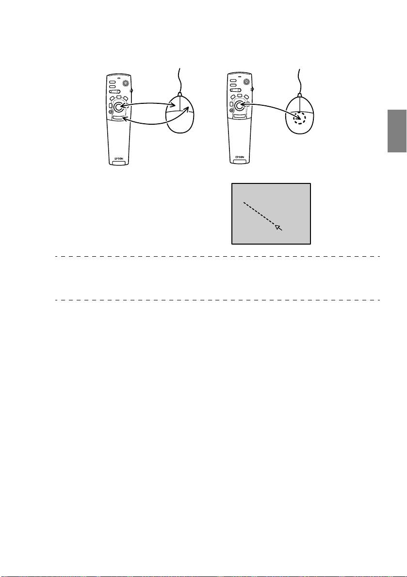
Perform the following mouse operations after the connection has been established:
Left click - - - - - - - - - - - - - - - - Press the [Enter] button.
Right click - - - - - - - - - - - - - - -Press the [Esc] button.
Mouse pointer movement- - - - Tilt the remote control [Enter] button
Power
Freeze
A/V Mute
R/C ON
E-Zoom
OFF
3
4
2
5
1
Enter
Esc
Remote Control
[Enter]
button
[Esc]
button
Mouse
Remote Control
Power
Freeze
A/V Mute
[Enter]
R/C ON
E-Zoom
OFF
button
3
4
2
5
1
Enter
Esc
Mouse
Point
· The operations will be reversed if the left/right button functions of the mouse have been
amended with the computer.
· The mouse cannot be used when the Effect, P in P and E-Zoom functions are in use.
Connecting the projector to a computer - 27
Page 30
Connecting Video Equipment
T
Switch off the power supply to the projector and video equipment prior to attempting to
make the connection.
Point
The audio signals output the selected image’s sound.
In the case of composite image signals
· Connect the projector’s Video port to the video equipment with the supplied RCA video
cable (Yellow).
· Connect the L-Audio-R port with the RCA audio cable supplied (red/white) to output sound
from the projector's speakers.
Audio port (White)
Video port (Yellow)
Audio port (Red)
To the audio output port L (white)
o the audio output port R (red)
To the video output port (yellow)
RCA video cable
(supplied with the projector)
RCA audio cable (supplied with the projector)
In the case of S image signals
· Connect the projector’s S-Video Port to the video equipment with the S-Video cable (available
on the open market).
· Connect the supplied RCA audio cable (Red/White) to the S-Audio/Audio 2 port if the
sound is to be output from the projector’s speakers.
Audio port (White)
To the audio output port L (white)
To the audio output port R (red)
S-Video port (Yellow)
To the S-Video output port
S-Video cable
(available on the open market)
RCA audio cable (supplied with the projector)
Audio port (Red)
28 - Connecting Video Equipment
Page 31

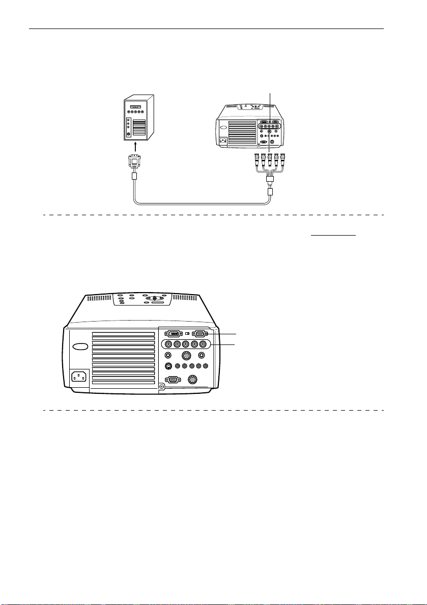
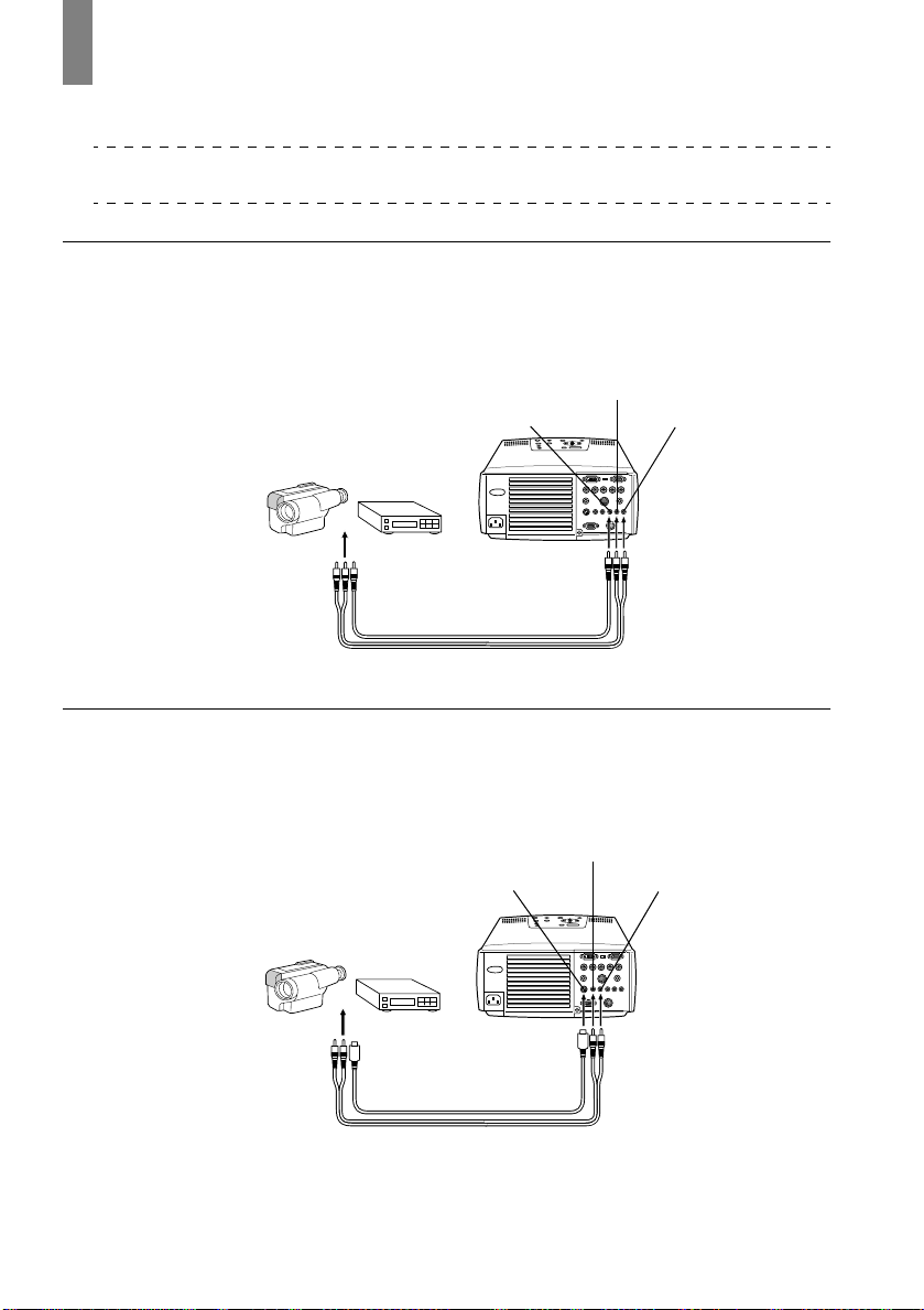
In the case of component (color differential*) image signals
· Connect the projector’s Computer 2-BNC port to the video equipment with the component
image cable (available on the open market) so that the following table is supported.
Video equipment R-Y(Cr) Y B-Y(Cb)
Projector R/Cr/Pr G/Y B/Cb/Pb
· Connect the S-Audio/Audio 2 port with the RCA audio cable supplied (red/white) to output
sound from the projector's speakers.
R/Cr/Pr port
G/Y port
B/Cb/Pb port
Audio port (White)
Audio port (Red)
To the audio output port L
To the audio output port R
(white)
(red)
To the R-Y (Cr) output port
To the Y output port
To the B-Y (Cb) output port
Component images cable
(available on the open
market)
RCA audio cable (supplied with the projector)
Point
· A conversion connector (available on the open market) is required on the projector's BNC
port when a component image cable is connected. Align the connector on the video side
with the port on the user’s video equipment.
· Set the BNC parameter to [YCbCr] when the connection has been established. (see
page 59)
Connecting Video Equipment - 29
Page 32

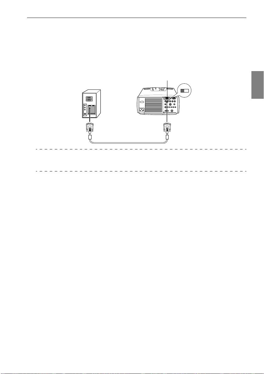
In the case of RGB image signals
· Connect the projector’s Computer 2-BNC port to the video equipment with the component
image cable (available on the open market).
· Connect the supplied RCA audio cable (Red/White) to the S-Audio/Audio 2 port if the
sound is to be output from the projector’s speakers.
G/Y port
R/Cr/Pr port
B/Cb/Pb port
Audio port (White)
Audio port (Red)
To the audio output port L
To the audio output port R
(white)
(red)
To th e R out pu t po rt
To th e G ou tpu t port
To the B output port
Component images cable
(available on the open
market)
RCA audio cable (supplied with the projector)
Point
· Purchase the component image cable so that one end matches the BNC type port on the
projector and the other matches the port on the video equipment.
· Set the BNC parameter to [RGB] when the connection has been established. (see
page 59)
30 - Connecting Video Equipment
Page 33

Projection
Images can be projected after all connections have been completed.
Preparations
Wa rn i ng
· Never look directly into the lens once the power supply has been switched on. Failure to
observe this may result in the powerful light damaging eyesight.
· Ensure that the power cord supplied is used. The use of cables other than the one supplied
may result in the outbreak of fire or electric shocks.
Caution
Do not perform any projection tasks with the lens cover attached. Failure to observe this may
result in the cover becoming malformed due to heat.
Connect the projector to a computer and video equipment. (see page 18, 28)
1
Remove the lens cover.
2
Attach the supplied power cord to the projector.
3
Check to confirm the shape of the projector’s power inlet and power connector, align the
connector in the correct direction, and then insert it as far as it will go.
Power inlet
Power connector
Plug the power plug into the power socket.
4
The operation indicator will be illuminated in orange.
Operation indicator
Illuminated in orange
Point
Button operations are not possible when the operation indicator is blinking in orange.
Power cord
Projection - 31
Page 34

Commencing Projection
Press the [Power] button to turn on the power supply.
1
The operation indicator will begin to blink in green, and projection will be started.
Power
Power
Computer
A/V mute
Resize
Menu
Help
Video
Shift
Esc
n
c
y
.
S
T
r
g
a
n
c
i
k
k
i
c
n
a
g
r
T
S
.
y
c
n
Keystone
Volume
Power
Set the R/C ON OFF switch to [ON] first of all
when using the remote control
Freeze
A/V Mute
Power
R/C ON
E-Zoom
OFF
3
4
2
5
1
Enter
Esc
The operation indicator will blink and then be illuminated in green after approximately
thirty seconds.
A message stating [No image
signals input] will be displayed
when no image signals have
been input.
(Depending on the setting,
this may not be displayed.
(see page 59
))
Operation indicator
Blinking in green → Illuminated
Point
Button operations are not possible when the operation indicator is blinking in green.
32 - Projection
Page 35

Select the port to which the connection has been made when more than one item of
2
equipment has been connected.
Press the port button connected to the computer or video equipment to switch the input
source.
Esc
Menu
Comp1
Auto
P in P Preset
- Volume +
Help
Comp2/YCbCr
Video
Resize
Comp2/YCbCr
Video
Computer
Video
Power
Computer
A/V mute
Resize
Menu
Help
Video
Shift
Esc
n
c
y
.
S
T
r
g
a
n
c
i
k
k
i
c
n
a
g
r
T
S
.
y
c
n
Keystone
Volume
Comp1
Connected
Port
Computer 1 port [Computer]
BNC port (RGB) BNC(RGB)
BNC port
(YCbCr)
(will change whenever pressed)
[Video]
(will change whenever pressed)
Video port [Video]
S-Video port S-Video
Button to Select Display at the top
Main Unit Remote Control
[Comp1] Computer1
[Comp2/ YCbCr] BNC(RGB)
(will change whenever pressed)
right-hand corner of
the screen
BNC(YCbCr)
Vid eo
Point
· Projection will take place without pressing the button if only one item of equipment is connected.
· Computer 1 when no input signals are detected despite the connection being in place and
when the images for the connected equipment are not output.
· The BNC port source that switches between [Computer] and [Video] on the main unit and
[Comp2/YCbCr] on the remote control can only display either BNC (RGB) or BNC
(YCbCr), depending on the BNC setting. (see page 59
)
Projection - 33
Page 36

Starting projection.
3
Switch on the power supply to the computer or video equipment. If the equipment connected is video equipment, then also press the [Playback] or [Play] buttons.
The [No Signal] display will be erased, and projection will commence.
Point
· If [No Signal] remains displayed, check the connections once again.
· Depending on the computer, there are cases when it is necessary to switch the image sig-
nal output destination with the key ( , etc.) or the settings after establishing the connection.
NEC Panasonic To s h i ba IBM SONY FUJITSU Macintosh
[Fn]+[F3] [Fn]+[F3] [Fn]+[F5] [Fn]+[F7] [Fn]+[F7] [Fn]+[F10] After rebooting the control panel
The table shown above provides examples for certain products. Refer to the computer’s
instruction manual for further details.
· Press the [Resize] button when signals that support DVD players or wide television
screens (16:9 images) have been input. The parameters will change between 4:3 images
and 16:9 images whenever the switch is pressed.
· There are cases where a projected image will remain projected if a still image is projected
for a long period of time.
monitor and sound to be set to
mirroring
34 - Projection
Page 37

Ending
End projection in accordance with the following procedure.
Press the [Power] button.
1
A message to confirm that the power needs to be switched off will be displayed.
Power
Power
Press the [Power] button once more.
2
Computer
A/V mute
Resize
The lamp will be extinguished, the operation indicator will blink in orange, and the cooldown process will commence.
(Power OFF?)
Menu
Help
Video
Shift
Esc
n
c
y
.
S
T
r
g
a
n
i
k
c
a
r
c
k
i
n
g
T
S
.
y
c
n
Keystone
Volume
Power
Freeze
A/V Mute
Power
R/C ON
E-Zoom
OFF
3
4
2
5
1
Enter
Esc
Please press Key again
Power
to power off.
Power
Power
Computer
A/V mute
Resize
The operation indicator will change from blinking to being illuminated in orange once the
cool-down process has been completed. The amount of time required for the cool down is
approximately forty seconds (may be longer depending on the ambient temperature).
Point
· Press a different button if the power is not to be switched off. The message will be erased
after seven seconds if no buttons are pressed (the power will remain on).
· It is also possible to end projection by pressing the [Power] button as explained in procedure #1 for more than one second (will assume the same status as if ending with procedure #2).
· Button operations are not possible when the operation indicator is blinking in orange. In
this event, please wait until full illumination has been attained.
Menu
Help
Video
Shift
Esc
n
c
y
.
S
T
r
g
a
n
c
i
k
k
i
c
n
a
g
r
T
S
.
y
c
n
Keystone
Volume
Power
Freeze
A/V Mute
Power
R/C ON
E-Zoom
OFF
3
4
2
5
1
Enter
Esc
Ending - 35
Page 38

Check to confirm that the operation indicator is illuminated in orange, and then unplug
3
the power plug from the socket.
Operation indicator
Illuminated in orange
Caution
Do not remove the power plug from the socket when the operation indicator is blinking in
orange. Failure to observe this may result in damage to the equipment and will speed up the
period for replacing the lamp.
Set the R/C ON OFF switch to [OFF] when using the remote control.
4
Power
Freeze
A/V Mute
R/C ON
E-Zoom
OFF
3
4
2
5
1
Enter
Point
The batteries are being consumed when the [R/C ON OFF] switch on the remote control is
set at [ON]. Ensure that the [R/C ON OFF] switch on the remote control is set to [OFF]
when not in use.
Restore the front foot if it has been extended.
5
Steady the projector by hand, and then lift the foot adjust lever with a finger and gently
lower it into the main unit.
Attach the lens cover.
6
36 - Ending
Foot adjust lever
Page 39

Adjusting the Projection Position
The projector can be adjusted into the following vertical projection positions.
Feet Adjustments
Adjusts the projection angle of the projector. As far as possible, make the necessary adjustments while making sure that the projector is facing the screen at right angles.
Lift the foot adjust lever with a finger and raise the front part of the projector.
1
The front foot will protrude.
Foot adjust lever
Remove your finger from the foot adjust lever, and then let go of the projector.
2
Rotate the lower part of the front foot to minutely adjust the height.
3
Becomes lower
Becomes higher
Point
· There are cases where the screen will be distorted into a trapezoid shape when foot
adjustments are performed. This trapezoid distortion can be adjusted with the use of the
trapezoid correction function. (see page 38
· The front foot is restored by lifting the foot adjust lever with a finger and lowering the projector.
)
Adjusting the Projection Position - 37
Page 40

Adjusting the projection size
It is possible to adjust the size of the projection and correct any trapezoid distortion.
Point
A function to resize the screen (see page 45) and an E-Zoom function for enlarging certain
areas (see page 47
Zoom Adjustment
Rotate the zoom ring to make the required adjustments (enlargment up to a maximum
1
of 1.3x is possible).
) are also available.
Becomes larger
Becomes smaller
The projection distance must also be adjusted when enlarging the screen. (see page 16
Point
If optional lenses are to be used, refer to the relevant instruction manuals for further details.
Keystone Adjustment
Make the necessary adjustment when the screen has been distorted into a trapezoid with foot
adjustment.
Press the [Keystone +, -] button to lengthen the screen sidewards.
1
Keystone
Volume
Power
Computer
A/V mute
Resize
Menu
Help
Video
Esc
n
c
y
.
S
T
r
g
a
n
c
i
k
k
i
c
n
a
g
r
T
S
.
y
c
n
Keystone
Volume
Shift
Keystone
Volume
The corrected screen will shrink in size. The corrected screen will shrink in size.
Point
· The screen will be reduced in size when keystone correction has been performed.
· The status of keystone correction will be recorded. Perform readjustments that match the
installation position when the projection position or angle have been changed.
· Reduce the sharpness if blurring occurs after keystone correction. (see page 57
· Keystone correction is performed from the menu. (see page 59
Computer
Power
A/V mute
Menu
Help
Video
Resize
Esc
n
c
y
.
S
T
r
g
a
n
c
i
k
k
i
c
n
a
g
r
T
S
.
y
c
n
Keystone
Volume
Shift
)
)
)
38 - Adjusting the projection size
Page 41

Picture Quality Adjustment
Adjusts image focus and disturbance.
Focus Adjustment
Aligns the focus of the image.
Rotate the focus ring to make the required adjustment.
1
Point
· It is not possible to align the focus if the lens is dirty or fogged over with condensation. In
this event, clean the lens accordingly. (see page 81
· Correct adjustment is not possible if the installation position is out of line by between 1.1
and 14.6 meters (3.6 ft. and 48.1 ft.).
· If optional lenses are to be used, refer to the relevant instruction manuals for further
details.
Auto Adjustment (when projecting computer images)
Automatically adjusts the computer image to attain the optimum effect. The items adjusted
include the tracking, position and synchronization.
)
Press the [ (Enter)] button on the projector (the [Auto] button on the remote control).
1
Esc
Menu
Comp1
Auto
P in P Preset
- Volume +
Help
Comp2/YCbCr
Video
Resize
Computer
A/V mute
Power
Resize
Menu
Help
Video
Esc
n
c
y
.
S
T
r
g
a
n
c
i
k
k
i
c
n
a
g
r
T
S
.
y
c
n
Keystone
Volume
Shift
Auto
Point
· If auto adjustments are initiated when the E-Zoom, A/V Mute or P in P functions are executing, adjustment will not be carried out until the executing function has been cancelled.
· Depending on the type of signals being output by the computer, there are cases when
adjustment cannot be carried out correctly. In this event, adjust the tracking and synchronization. (see page 40
)
Picture Quality Adjustment - 39
Page 42

Tracking Adjustments (when projecting computer images)
Adjusted when vertical stripes are apparent on the computer image.
Press the [Tracking +, -] button on the projector.
1
n
c
y
.
S
T
g
n
i
k
c
r
a
c
k
i
n
a
g
r
T
S
.
y
c
n
Synchronization Adjustments (when projecting computer images)
Adjusted when flashing, blurring and vertical noise are apparent on the computer image.
Press the [Sync +, -] button on the projector.
1
n
c
y
.
S
T
r
g
n
i
k
c
a
r
a
c
k
i
n
g
T
S
.
y
c
n
Calling Out Adjustment Values (when projecting computer images)
It is possible to record preset adjustment values and call them out when required.
Press the [Preset] button on the remote control.
1
The pre-registered numbers between preset #1 and preset #5 will change in sequence
whenever this button is pressed.
Esc
Menu
Help
Comp1
Comp2/YCbCr
Video
Resize
Auto
P in P Preset
- Volume +
Preset
Point
· There are cases when these adjustments must be made again if the values output from
the computer (resolution, display color) are amended after flashing and blurring have
been adjusted.
· There are cases where flashing and blurring are caused by adjusting the brightness and
contrast*.
· Images will be projected more vividly if synchronization adjustments are made after the
tracking adjustments.
· Auto adjustments, tracking adjustments and synchronization adjustments are not possible
if no image signals are being input by the computer, such as when projecting video
images or displaying menus.
· The preset values must be registered beforehand. (see page 57
)
40 - Picture Quality Adjustment
Page 43

Introduction of Functions
The functions that can be operated by pressing buttons when images are being projected are
listed below.
Button
Function Outline
Help Displays the method of solving prob-
A/V Mute Temporarily mutes the image and
Freeze Freezes the image. Freeze 44
Resize Changes the size of the image. Resize Resize 45
E-Zoom Enlarges the image. E-Zoom 47
Effect Adds decorations to the image. Effect 48
P in P Adds a sub-screen to the image. P in P 51
Preset Calls out pre-registered adjustment val-
Keystone
correction
Auto
adjustment
Tracking Adjusts vertical stripes that appear on
Synchronization
Volume Adjusts the volume. Shift + Vol-
Menu Displays the menu. Menu Menu 55
lems when trouble occurs.
sound.
ues.
Corrects trapezoid distortion. Keystone 38
Automatically adjusts the image for
optimum effect.
the image.
Adjusts flashing, blurring and vertical
noise that appears on the image.
Main Unit
Help Help 42
A/V Mute A/V Mute 44
(Enter)
Tracking 40
Sync 40
ume
Remote
Control
Preset 40
Auto 39
Vo l u m e 5 2
Reference
Page
Introduction of Functions - 41
Page 44

Useful Functions
Help Function
The methods of solving trouble when it occurs are devided into separate sections and explained
below for use when problems arise.
Press the [Help] button.
1
The help menu will be displayed.
Help
Select the item.
2
Power
Computer
A/V mute
Resize
Menu
Help
Video
Shift
Esc
n
c
y
.
S
T
r
g
a
n
i
k
c
c
k
i
n
a
g
r
T
S
.
y
c
n
Keystone
Volume
Help
Press the [Sync+, -] button on the main unit (tilt the [Enter] button up and down on the
remote control) to select the item.
(HELP Menu)
Help for the image
Help for the sound
Language selection(Language)
If you follow the instructions to solve the problem
unsuccessfully, unplug the power from the wall outlet and
contact with your local dealer.
Esc
Menu
Comp2/BNC
Comp1
Auto
P in P Preset
- Volume +
Help
Video
Resize
Set the item.
3
Set the item by pressing the [ (Enter)] button on the main unit (the [Enter] button on the
remote control).
42 - Useful Functions
:Select :Exit:Enter
Enter
Freeze
A/V Mute
Power
R/C ON
E-Zoom
OFF
3
4
2
5
1
Enter
Esc
Page 45

Repeat the operations explained in procedures 2 and 3 to select and set the detailed
4
items.
(HELP Menu)
An image does not appear on the Screen.
The image is not in focus.
The image is blurred.
The image is not displayed fully on the Screen.
(cut off/too big/too small/partial)
The colors of the image are not correct.
The image is too dark.
The image is trapezoid.
:Select :Return:Enter :Exit
Point
· Refer to "Troubleshooting" in this manual if the help text does not solve your problems.
(see page 70
· The help menu can be canceled by pressing the [Esc] or [Help] buttons.
)
Useful Functions - 43
Page 46

Projection Cutting
It is possible to temporarily erase and stop images and sound.
A/V Mute Function
Temporarily erases images and sound. It is also possible to project the user logo at this time.
Press the [A/V Mute] button.
1
The images and sound will be erased.
Power
A/V mute
Computer
A/V mute
Resize
Will be canceled when the [A/V Mute] button is pressed again, when the volume is
adjusted, or when the menu is displayed.
Depending on the setting, three different types of statuses may be selected when temporarily erasing images and sound. (see page 59
Black color Blue color User logo
Menu
Help
Video
Shift
Esc
n
c
y
.
S
T
r
g
n
i
k
a
c
k
i
c
n
a
g
r
T
S
.
y
c
n
Keystone
Volume
A/V Mute
Freeze
A/V Mute
Power
R/C ON
E-Zoom
OFF
3
4
2
5
1
Enter
Esc
)
Point
The EPSON logo has been registered in the user logo. User logo registration and setup is
necessary to amend the user logo. (see page 60
)
Freeze Function
Temporarily freezes the image; however, the sound will not be muted.
Press the [Freeze] button.
1
The image will freeze.
Power
Freeze
A/V Mute
R/C ON
E-Zoom
Freeze
Press the [Freeze] button once more to cancel this mode.
44 - Projection Cutting
OFF
3
4
2
5
1
Enter
Esc
Page 47

Switching Image Sizes
The window display and resizing display are switched when projecting images onto a computer. Video image projections are switched between an aspect ratio of 4:3 and 16:9.
Press the [Resize] button.
1
The screen size will switch.
Resize
Power
Computer
A/V mute
Resize
Menu
Help
Video
Shift
Esc
n
c
y
.
S
T
r
g
a
n
c
i
k
k
i
c
n
a
g
r
T
S
.
y
c
n
Keystone
Volume
● In the case of computer images
Windows display: Projected at the entered resolution. There are cases where the projection size
and the image size are different.
Resizing display: Projected with the resolution reduced or expanded so that the image fits the
entire size of the projection.
Example: In the case of 800 x 600
Resizing display Window display
Esc
Menu
Comp1
Auto
P in P Preset
- Volume +
Help
Comp2/YCbCr
Video
Resize
Resize
Example: In the case of 1,600 x 1,200
Resizing display Window display
Point
· The size will not be switched if the display resolution of the liquid crystal is the same as
the entered resolution (1,024 x 768 dots).
· A certain portion of the image will not be displayed if the entered resolution is larger than
the display resolution of the liquid crystal. Tilt the [Enter] button on the remote control to
scroll through the areas not displayed.
· Certain areas on the right and left will not be displayed when SXGA (1,280 x 1,024 dots)
is being displayed. Press the [Resize] button while pressing the [Shift] button on the main
unit to obtain a full-screen display.
Switching Image Sizes - 45
Page 48

● In the case of video images
Switching will be performed for 4:3 and 16:9 image sizes. Images recorded with digital videos
and DVD images can be projected on 16:9 wide screens.
4:3 display 16:9 display
46 - Switching Image Sizes
Page 49

Enlarging Images (E-Zooming function)
It is possible to enlarge projected sizes without amendment.
Press the [E-Zoom] button.
1
The size percentage will be displayed in the bottom right-hand corner to enable the image
to be reduced or enlarged.
The size percentage will be displayed.
Power
Freeze
A/V Mute
R/C ON
E-Zoom
OFF
3
4
E-Zoom
Point
· Enlargement is possible with 24 stages between 1x and 4x at increments of 0.125x.
· A certain portion of the image will not be displayed when it has been enlarged. Tilt the
[Enter] button on the remote control to scroll the screen and display this portion accordingly.
· Sub-screens will be enlarged when the P in P function is being used.
2
5
1
Enter
Esc
Enlarging Images (E-Zooming function) - 47
Page 50

Effect Function
The [Effect] buttons add decorations to images displayed during presentations. The decoration settings can be amended on the effect menu. (see page 58
Cursor/Stamp
Imprints a stamp on the image.
Press the [1] button.
1
The selection will switch between three different cursor/stamps whenever the [1] button
is pressed.
Tilt the [Enter] button on the remote control to move the position of the cursor/stamp.
2
The stamp will be imprinted at the location of the cursor when the [Enter] button on the
3
remote control has been pressed.
Point
· The effect function will be canceled and the cursor will disappear when the [Esc] button is
pressed.
· The decoration will be erased when the [5] button is pressed.
· The mouse cannot be used when the effect function is in progress.
)
Box
Draws a box on the image.
Press the [2] button.
1
Tilt the [Enter] button on the remote control to move the cursor to the starting position.
2
Press the [Enter] button to set the start position.
3
48 - Effect Function
Page 51

Tilt the [Enter] button on the remote control to move the cursor to the ending position.
4
Press the [Enter] button to set the end position.
5
Point
· The effect function will be canceled and the cursor will disappear when the [Esc] button is
pressed prior to setting the position.
· The decoration will be erased when the [5] button is pressed.
· There are cases where the effect will be difficult to see depending on the color combina-
tion of the image's background and the box. Amend the color of the box in this event. (see
page 58)
· The mouse cannot be used when the effect function is in progress.
Spotlight
Shines a spotlight on a certain part of the image.
Press the [3] button.
1
Will switch between three different spotlight sizes whenever the [3] button is pressed.
Tilt the [Enter] button to move the spotlight.
2
Point
· The effect function will be canceled and the spotlight will disappear when the [Esc] button
is pressed.
· The mouse cannot be used when the effect function is in progress.
Effect Function - 49
Page 52

Bar
Draws a bar line on the image.
Press the [4] button to display the required cursor/stamp.
1
The selection will switch between three different bars whenever the [4] button is pressed.
Tilt the [Enter] button to set the end position.
2
Point
· The effect function will be canceled and the bar will disappear when the [Esc] button is
pressed.
· There are cases where the effect will be difficult to see depending on the color combination of the image's background and the bar. Amend the color of the bar in this event. (see
page 59)
· The mouse cannot be used when the effect function is in progress.
Canceling Effects
Press the [5] button.
1
The boxes, bars and other effects will disappear.
50 - Effect Function
Page 53

P in P Function
The video image will be displayed as a sub-screen inside the computer image or video image.
Press the [P in P] button.
1
Operation instructions will be displayed at the bottom left-hand side of the screen and the
sub-screen will be displayed at the top right-hand side of the main screen.
Tilt the [Enter] button on the remote control to move the position of the sub-screen.
2
Press the [E-Zoom] button to change the size of the sub-screen.
3
Press the [1] button to switch across to sub-screen sound.
4
Press the [2] button to return to the main-screen sound after the sound has been switched.
Press the [Enter] button to set the sub-screen display.
5
The operation guide in the bottom left-hand corner will be erased.
Point
· The sub screen will be erased when the [P in P] button is pressed again.
· The computer image or video image will be displayed in the main screen and the video
image (Video, S-Video) will be displayed in the sub-screen, and the video image on the
sub screen can be amended with the P in P settings. (see page 59
· Switch the position, size, and sound of the sub-screen prior to fixing the sub-screen's display.
· The sub-screen can be switched between five different sizes.
)
P in P Function - 51
Page 54

Volume Adjustment
The volume can be amended when sound is emitted from the projector speakers.
Press the [Volume+, -] button while pressing the [Shift] button ([Volume+, -] button on
1
the remote control).
Power
Menu
Help
Video
Shift
Keystone
Volume
Computer
A/V mute
Resize
Esc
n
c
y
.
S
T
r
g
a
n
c
i
k
k
i
c
n
a
g
r
T
S
.
y
c
n
Keystone
Volume
Shift
- Volume +
Point
Adjustment is not possible when no sound signals are being input.
Esc
Menu
Comp1
Auto
P in P Preset
- Volume +
Help
Comp2/YCbCr
Video
Resize
52 - Volume Adjustment
Page 55

Menu Configuration
Brightness
Contrast
Sharpness
Gamma
Reset Execute
:
:
:
:
0
0
0
Video
Audio
Effect
Setting
Capture
Advanced
About
Reset All
NormalDynamic Natural
:Select :Enter
The setup menu enables the various adjustments and settings to be made.
Menu Items
The menus are split into top menus and sub menus and consist of a hierarchy structure. Also,
the image menu will differ in accordance with the input source (connected port).
Top menus Sub menus (image)
● Menu items
Image menu · Computer (D-Sub 15/BNC) Image menu · Computer (DVI-D)
Video
Audio
Effect
Setting
Capture
Advanced
About
Reset All
:Select :Enter
Image menu · Video (Video/S-Video) Image menu · Vi deo (BN C)
Video
Audio
Effect
Setting
Capture
Advanced
About
Reset All
:Select :Enter
Position
Tracking
Sync.
Brightness
Contrast
Sharpness
Gamma
Resolution
Preset
Reset
Position
Brightness
Contrast
Color
Tint
Sharpness
Gamma
Smooth Motion
Video Signal
Reset
Video
Audio
Effect
Setting
Capture
Advanced
About
Reset All
Position
Tracking
Sync.
Brightness
Contrast
Sharpness
Gamma
Resolution
Preset
Reset
:
:
:
:
:
:
:
[]
:Select :Enter
Adjustment
9999
:
99
:
0
:
0
:
0
:
:
NormalDynamic Natural
:
Auto
Manual
[]
Select
Execute
Adjustment
0
:
0
:
0
:
0
:
0
:
:
NormalDynamic Natural
:
ON
Select [Auto ]
Execute
Select
OFF
Adjustment
9999
99
0
0
0
NormalDynamic Natural
Auto
Manual
Select
Execute
Video
Audio
Effect
Setting
Capture
Advanced
About
Reset All
:Select :Enter
Select
Position
Brightness
Contrast
Color
Tint
Sharpness
Gamma
Smooth Motion
Video Signal
Reset
Adjustment
0
:
0
:
0
:
0
:
0
:
:
NormalDynamic Natural
:
ON
Select [Auto ]
Execute
OFF
Point
· The items displayed on the image menu will differ in accordance with the projected input
source, and menus other than that belonging to the projected input source cannot be
adjusted.
· The image menu cannot be adjusted when no image signals are being input.
Menu Configuration - 53
Page 56

Sound menu Effect menu
Video
Audio
Effect
Setting
Capture
Advanced
About
Reset All
:Select :Enter
Volume
Treble
Bass
SRS SPACE
SRS CENTER
Reset
0
:
0
:
0
:
0
:
0
:
Execute
Video
Audio
Effect
Setting
Capture
Advanced
About
Reset All
:Select :Enter
Setup menu Capture menu
Video
Audio
Effect
Setting
Capture
Advanced
About
Reset All
:Select :Enter
Keystone
P in P
No-Sigual Msg.
Prompt
A/V Mute
BNC
Sleep Mode
Reset
0
:
Composite S-Video
:
OFF Black
:
ON OFF
:
Black Blue
:
RGB YCbCr
:
:
ON OFF
Execute
Blue
Logo
Logo
Video
Audio
Effect
Setting
Capture
Advanced
About
Reset All
:Select :Enter
Advance settings menu Information menu
Video
Audio
Effect
Setting
Capture
Advanced
About
Reset All
Language
Startup Screen
Color Setting
Comp2Sync Termination
Rear Proj.
Ceiling
Reset
:
:
:
:
Select [English]
ON OFF
Auto Manual
ON: OFF
ON OFF
ON OFF
Execute
Select
Video
Audio
Effect
Setting
Capture
Advanced
About
Reset All
1 Cursor/Stamp
2 Box
3 Spotlight
4 Bar
Cursor Speed
Reset
User's Logo Capture
Lamp ON Time
Video Source
Frequency
Sync Polarity
Sync Mode
Resolution
Refresh Rate
Setting
Setting
Setting
Setting
:L
Execute
:
9999 H
:
Computer
:
H 999. 99 KHz
:
V 999. 99 Hz
:
H Positive
:
V Negative
:
Sync On Green
:
9999x9999
:
999. 9 Hz
M H
Execute
:Select :Enter
:Select :Enter
The information menu displays the lamp
illumination time and the setup status of the
projected input source
All reset menu
Video
Audio
Effect
Setting
Capture
Advanced
About
Reset All
:Select :Enter
Execute
Point
The lamp illumination time is displayed in units of 0H between 0 and 10 hours, and in units
of 1 hour above 10 hours.
54 - Menu Configuration
Page 57

Menu Operations
The menus can be operated from both the projector and the remote control.
Operation Method
Press the [Menu] button.
1
The top menu will be displayed.
Power
Menu
Select the required item.
2
Computer
A/V mute
Resize
Press the [Sync +, -] button on the projector (tilt the [Enter] button up or down on the
remote control) to select the required item.
Set the selected item.
3
Press the [ (Enter)] button on the projector (the [Enter] button on the remote control) to
set the selected item.
The sub-menu will be displayed.
Then select the detailed sub item.
4
Press the [Sync +, -] button on the projector (tilt the [Enter] button up or down on the
remote control) to select the sub item.
The items displayed on the image menu and information menu will differ in accordance
with the projected input source.
Menu
Help
Video
Shift
Esc
n
c
y
.
S
T
r
g
a
n
i
c
k
k
i
c
n
a
g
r
T
S
.
y
c
n
Keystone
Volume
Video
Audio
Effect
Setting
Capture
Advanced
About
Reset All
Menu
Esc
Menu
Comp2/YCbCr
Comp1
Auto
P in P Preset
- Volume +
Help
Video
Resize
Language
Startup Screen
Color Setting
Comp2Sync Termination
Rear Proj.
Ceiling
Reset
:
:
:
:
Select [English]
ON OFF
Auto Manual
ON: OFF
ON OFF
ON OFF
Execute
Select
Menu Operations - 55
Page 58

Select the parameter value.
5
Press the [Tracking +, -] button on the projector (tilt the [Enter] button left or right on the
remote control) to select the parameter value.
Language
Startup Screen
Color Setting
Comp2Sync Termination
Rear Proj.
Ceiling
Reset
Select [English]
:
ON OFF
:
Auto Manual
:
ON OFF
:
ON OFF
Execute
ON: OFF
Select
Point
· (Enter) is attached to the rear of the sub item names that execute the parameters and
continue onto the lower hierarchies. Press the [Enter] button to set this selection, and then
select the parameter setting again.
· Refer to the list of settings for further information on the function of each setting. (see
page 57)
Set all of the other items in the same way.
6
Press the [Menu] button.
7
The menu will end.
Point
· Press the [Esc] button to return to the previous menu in the hierarchy.
· The items displayed on the image menu will differ in accordance with the projected input
source, and menus other than that belonging to the projected input source cannot be
adjusted.
· Image menus cannot be adjusted when no image signals are being input.
· The last setup screen will be displayed when a menu is ended and then displayed again
(the same status as immediately prior to ending the menu with procedure #7.)
56 - Menu Operations
Page 59

Setting Items
To p
Menu
Video Position Moves the image’s display position up, down, left and right.
Sub Menu Function Default Value
Press the [Enter] button to make the required adjustments on
the adjustment screen displayed.
Tracking Adjusts vertical stripes that appear on the computer image. Depends on the
Sync. Adjusts disturbance, blurring and vertical noise that appear
Brightness Adjusts the brightness of the image. Center value
Contrast* Adjusts the contrast of the image. Center value
Color Adjusts the color depth of the image. Center value
Tint Adjusts the tint of the image. Center value
Sharpness Adjusts the sharpness of the image. Center value
Gamma Corrects the color vividness of the image.
Resolution Sets the input resolution.
Preset It is possible to save the current computer input signal
Smooth Motion Images, etc., will move smoothly when seen after this has
on the computer image.
· Disturbance and blurring may occur as a result of adjusting
the brightness and contrast*.
· It is possible to regulate the vividness of the image by
adjusting the synchronization after adjusting the tracking.
Dynamic: Produces an image with clear color differences.
Normal: Projects tint without correction.
Natural: Produces an image with natural tint. Suitable for
Auto: Automatically adjusts the input resolution.
Manual: Press the [Enter] button and select the required set-
adjustment values (input resolution, tracking, synchronization signals, brightness, contrast, sharpness, gamma and display position).
Press the [Enter] button and select the preset number under
which registration is to be performed from the preset selection menu displayed.
· The adjustment values registered under a preset number
· The preset adjustment values can be called out by pressing
been set at [ON]. Set this at [OFF] if the colors appear to
flicker.
Suitable for displaying plans, etc.
video images.
ting from the input resolution selection menu displayed.
represent the current status of the system. Ensure that the
optimum values have been set up before registering this
data.
the [Preset] button. (see page 40
)
Center value
connection
signals
0
Normal
Auto
Not registered
ON
Menu Operations - 57
Page 60

To p
Menu
Video Video Signal Sets the video signal method.
Audio Volume Adjusts the volume. 15
Effect Cursor/Stamp Sets the shape, size, color and length of the cursor/stamps
Sub Menu Function Default Value
Press the [Enter] button and select the required setting from
the video signal method selection menu displayed.
· The video signal method will be automatically set up in the
[Auto] mode, but do not use the [Auto] mode for the PAL
system (60Hz).
Reset Returns all image menu adjustment values to the default val-
Treble Adjusts the strength of the high tones. Center value
Bass Adjusts the strength of the low tones. Center value
SRS Space Adjusts the width of the sound. 2
SRS Center Adjusts the depth of the sound. 2
Reset Returns all sound menu adjustment values to the default val-
Box Set the color, shading and shape of the box allocated to the
Spotlight Sets the size of the spotlight allocated to the [3] button.
ues.
Press the [Enter] button and then select [Yes] on the confirmation screen displayed.
· Select [Reset All] to return all menu settings to the default
settings. (see page 61
ues.
Press the [Enter] button and then select [Yes] on the confirmation screen displayed.
· Select [Reset All] to return all menu settings to the default
settings. (see page 61
allocated to the [1] button.
Press the [Enter] button and select the item to be displayed
from the cursor/stamp setup menu. The shape, size, color
and length conditions can be set by pressing button types 1
to 3 respectively (depending on the selected cursor shape,
size, color and length cannot be set up.)
· The [1] button executes the cursor/stamp function. The
cursor/stamp types will be switched between 1 and 3
sequentially for each time the [1] button is pressed. (see
page 48)
[2] button.
Press the [Enter] button and select the required item from the
box setup menu.
· The [2] button executes the box function. (see page 48
Press the [Enter] button and select the required item from the
spotlight setup menu.
· The [3] button executes the spotlight function. (see page 49
)
)
)
)
Auto
-
-
Individual
settings
between types
1 to 3
Color: Magenta
Shading: No
Shape: Square
Size: Medium
58 - Menu Operations
Page 61

To p
Menu
Effect Bar Sets the color, direction and width of the bar allocated to the
Setting Keystone Adjusts trapezoid distortion.
Sub Menu Function Default Value
[4] button.
Press the [Enter] button and select the required item from the
bar setup menu. The color, direction and width can be
selected independently for each of the settings between 1
and 3.
· The [4] button executes the bar function. The bar types will
be switched between 1 and 3 sequentially for each time the
[4] button is pressed. (see page 50
Cursor Speed Selects the speed of Cursor.
Reset Returns all effect menu adjustment values to the default val-
P in P Sets the input source for the P in P function’s sub-screen.
No Signal Msg The status for [No Image Signal Input] and other message
Prompt Sets whether to display the input source on the screen or not. ON
A/V Mute Sets up the screen status for when the [A/V Mute] button is
BNC Sets the mode for the input image signals connected to the
L: Slow M: Medium H: Fast
ues.
Press the [Enter] button and then select [Yes] on the confirmation screen displayed.
· Select [Reset All] to return all menu settings to the default
settings. (see page 61
· The screen will be reduced in size when trapezoid
correction has been performed.
· The status of trapezoid correction will be recorded. Perform
readjustments that match the installation position when the
projection position or angle has been changed.
· Reduce the sharpness if blurring occurs after trapezoid
correction. (see page 57
· The P in P function is executed by pressing the [P in P]
button. (see page 51
display.
· The user logo must be registered and set up before it can be
amended.
pressed.
· The user logo must be registered and set up before it can be
amended.
BNC port.
RGB: Enables RGB signals to be input.
YCbCr: Enables video signals to be input (YCbCr or YPbPr.)
)
)
)
)
Individual
settings
between types
1 to 3
M
-
Center value
Composite
Blue
Black
RGB
Menu Operations - 59
Page 62

To p
Menu
Setting Sleep Mode Sets the energy-saving function for when no image signals
Capture
Advanced
Sub Menu Function Default Value
are being input. When this is set at [ON], projection will be
automatically ended and the projector will enter the sleep
mode if no image signals are input and no operations are
performed for a period of thirty minutes (the operation indicator will be illuminated in orange).
Press the [Power] button to restart projection.
Reset Returns all setting menu adjustment values to the default
User’s Logo
Capture
Language Sets the language with which messages are to be displayed.
Startup Screen Displays the user logo during warm-up after the power has
Color Setting Adjusts the color temperature* of the image.
values.
Press the [Enter] button and then select [Yes] on the confirmation screen displayed.
· Select [Reset All] to return all menu settings to the default
settings. (see page 61
Registers a user logo. (see page 62
Press the [Enter] button and follow the instructions displayed on the confirmation screen.
· The saving procedure requires a certain amount of time to
complete. Do not attempt to operate the projector or the
equipment connected to the projector while this procedure
is running. Failure to observe this may result in damage.
· The size that can be registered is 400 x 300 dots.
· The display size will be adjusted when video images are
being projected.
Press the [Enter] button and select the required language
from the language selection menu displayed.
been switched on.
· The user logo must be registered and set up before it can be
amended.
Auto: Automatically adjusts the color settings.
Manual: Press the [Enter] button and select the required item
from the color setting menu displayed.
· Set the color temperature value to the yardstick value.
· The black level and white level settings are only used when
multiple projectors are used in the stack formation.
)
)
ON
-
EPSON logo
English
ON
Auto
60 - Menu Operations
Page 63

To p
Menu
Advanced
About (Displays the current settings) -
Reset
all
Sub Menu Function Default Value
Comp2 Sync
Te rm i n a ti o n
Rear Proj. Set at [ON] to project images onto a half-transparent screen
Ceiling Set at [ON] to project images when suspended from the ceil-
Reset Returns all advanced setting menu adjustment values to the
Execute Resets all items in all setting menus to their default settings.
Sets the Computer 2 termination mode to enable image processing from a Port.
ON: Terminated in analog (75
OFF: TTL input
· Usually used at [OFF]. Set at on with the switcher when
analog (75
from the rear. The projected image will be inverted.
ing. The projected image can be be inverted from left to right
and up and down.
· The optional ceiling suspension unit is required to suspend
the projector from the ceiling. (see page 87
default values.
Press the [Enter] button and then select [Yes] on the confirmation screen displayed.
· Select [Reset All] to return all menu settings to the default
settings.
Press the [Enter] button and then select [Yes] on the confirmation screen displayed.
· Execute the [Reset] function from each individual sub menu
to return the image and sound settings to the default values
for each menu.
· The user logo, lamp illumination time, language and BNC
settings cannot be restored to the default values. Reset the
lamp illumination time after the lamp has been replaced.
(see page 86
Ω
) termination is required.
)
Ω
)
)
OFF
OFF
OFF
-
-
· The image menu and information displayed will differ in accordance with the projected input
source, and menus other than that belonging to the projected input source cannot be adjusted.
· The information menu displays the status of the input source settings being projected.
Menu Operations - 61
Page 64

User Logo Registration
Registers the images currently displayed as the user logo.
Displays the image that is to be registered as the user logo.
1
Press the [Menu] button and select [Capture] - [User’s Logo Capture].
2
The confirmation screen will be displayed.
Video
Audio
Effect
Setting
Capture
Advanced
About
Reset All
:Select :Enter
Select [Yes] and then press the [ (Enter)] button on the main unit (the [Enter] button
3
User's Logo Capture
Execute
on the remote control).
The image to be registered will be displayed.
User's Logo Capture
Do you use the present image
as a user's logo?
Yes No
:Select:Return :Execute
Adjust the position of the image and then press the [ (Enter)] button on the main unit
4
(the [Enter] button on the remote control).
The confirmation screen will be displayed.
62 - Menu Operations
:Select
:Return :Execute
/
Page 65

Select [Yes] and then press the [ (Enter)] button on the main unit (the [Enter] button
5
on the remote control).
The enlargement setup screen will be displayed.
User's Logo Capture
Do you use this image?
Yes No
:Select:Return :Execute
Select the enlargement rate and then press the [ (Enter)] button on the main unit (the
6
[Enter] button on the remote control).
The screen to confirm saving will be displayed.
User's Logo Capture
Set the zoom rate.
zoom rate :
100% 200% 300%
:Select:Return :Execute
Select [Yes] and then press the [ (Enter)] button on the main unit (the [Enter] button
7
on the remote control).
The image will be saved. Wait until the [saving completed] screen is displayed.
User's Logo Capture
Do you save the user's logo?
Yes No
If you save it,
the previous user's logo
will be overwritten.
:Select:Return :Execute
Point
· A certain amount of time is required for the saving process. Do not operate the projector
or connected equipment while saving is in progress. Failure to observe this may result in
defects.
· The image size that can be registered is 400 x 300 dots.
· The display size will be amended when the video image is being projected.
Menu Operations - 63
Page 66

Introduction of Projector Software
The projector software includes the following.
Outline of Projector Software
The various types of projector software available are explained below.
● EMP Link V
Enables the projector settings to be amended from the computer. This allows functions to be
allocated to the [Effect] button and a user logo to be edited (refer to the EMP Link V Users’
Guide (PDF)).
64 - Introduction of Projector Software
Page 67

Computer Connections
Establish a serial connection between the computer and projector when EMP Link V is being
used. The computer and projector can be connected together with serial.
Serial Connections
Caution
· Ensure that the power supply to the projector has been switched off before attempting to
establish the connection. Failure to observe this may result in equipment damage.
· Confirm the shape of the cable connector and the port before establishing the connection. If
connections are forced despite the connector and port being different shapes, it may result
in malfunctions and equipment damage.
Point
· Depending on the shape of the computer port, an adapter may be required for connection
purposes. Refer to the computer’s instruction manual for further details.
· The connected computer is used to amend the projector settings and to perform operations. Connect the computer that is required to output projection images to the Computer
1 or Computer 2 port. (see page 18
· Switch on the projector and ensure that the connection has been set up before using the
software.
● Windows Computers
Connect the projector’s Mouse/Com port to the computer ’s serial port with the use of the PC
serial cable and main cable supplied.
)
Mouse/Com port
PC SERIAL
Serial port
PC serial cable
(supplied with the projector)
Main cable
(supplied with the projector)
Computer Connections - 65
Page 68

● Macintosh Computers
Connect the projector’s Mouse/Com port to the computer ’s printer port or modem port with
the use of the Mac serial cable and main cable supplied.
Mouse/Com port
MAC SERIAL
Printer port or
Modem port
Mac serial cable
(supplied with the projector)
Main cable
(supplied with the projector)
66 - Computer Connections
Page 69

Installation
This section explains how to install the EMP Link V.
Operating Environment
Check the following to ensure that the software can operate on the computer in use.
● Windows Operating Environment
Win dow s
Operable computer NEC PC98-NX series or DOS/V computers operating on the Windows 95/98/
Available memory
capacity
Available hard disk
capacity
Display Resolution of 16bit High Color (640x480) or more
**20MByte or more is required for the Chinese and Korean languages.
● Macintosh Operating Environment
Operable computer Operating on Mac OS 7.6/8.0/8.1/8.5/8.5.1/8.6/9.0/9.0.4/9.1
Main memory
capacity
Available hard disk
capacity
Display 32,000 Color (640 x 480) or more
**15MByte or more is required for the Japanese language, and 25MByte or more is required for
the Korean language.
NT4.0/2000 platform
CPU: Pentium133MHz or more
32MByte or more (an additional 8MBytes when operating the Acrobat Reader)
· EMP Link V /EMP Link PDF User ’s Guide 5MByte or more
· Acrobat Reader 10MByte or more**
Macintosh
CPU: Power PC or more
32MBytes or more (22MByte when operating the Acrobat Reader)
· EMP Link V /EMP Link PDF User ’s Guide 5MByte or more
· Acrobat Reader 8MByte or more**
Installation - 67
Page 70

Installation
This section explains how to install the software using the Windows 98 screens. Software installation into the Windows 95 platform follows the same procedure.
Point
The EMP Link V User’s Guide is stored on the CD-ROM in the PDF format. As Acrobat
Reader is required to read this, it is recommended that it is installed at the same time as
EMP Link V for computers that do not have this function.
● In the case of Windows
Start up Windows and set the CD-ROM in place.
1
The set-up program will start automatically.
Point
If the set-up program does not start automatically, open the [Specify and execute file name]
dialog box from the [Start] – [Specify and execute file name] menu, and enter [CD-ROM
drive name: \SETUP].
Select the language and the program to be installed and then press the [OK] button.
2
Installation will then commence. Proceed with all subsequent screens in accordance with
the instructions provided.
Point
The program can be un-installed by selecting [EMP Link V] from the [My Computer] – [Control Panel] – [Add and Delete Applications] menu and then executing [Add and Delete].
68 - Installation
Page 71

● In the case of the Macintosh
Start up the Macintosh and then set the CD-ROM in place.
1
Double-click on the EMP Link Installer icon.
2
The set-up program will start up automatically.
Select the language and click on the [OK] button.
3
Proceed with all subsequent screens in accordance with the instructions provided.
Point
Drag the [EMP Link V] folder and [EMP Link V] contained in [System] – [Default Settings]
into the trash can to un-install the program.
Reading the User’s Guide
● In the case of Windows
Select [Start] – [Programs] – [EMP Link V] – [User’s Guide] to open the file.
● In the case of the Macintosh
Double-click on the [User’s Guide] icon contained within the [EMP Link V] folder to open the
file.
Installation - 69
Page 72

Troubleshooting
When you think you have a problem, first of all check the indicators on the projector.
The projector is fitted with operation indicator, lamp indicator and temperature indicator to
advise the user of the projector’s status.
Operation indicator
Lamp indicator
Temperature indicator
Operation Indicator
Indicator Status Cause Recovery or Status
Illuminated in
Orange
Blinking in
Orange
Illuminated in
Green
Blinking in
Green
Illuminated in
Red
Stand-by status (Not an error)
Cool-down
procedure in
progress
Projection in
progress
Warm - u p i n
progress
Internal error Cease operations, remove the power plug from
Projection will be started when the [Power]
button is pressed.
(Not an error)
· Wait for a moment. The amount of time for
the projector to cool down* (cooling the lamp)
will depend on the external temperature, etc.
· The [Power] button cannot be used during
the cool-down period. This will be
illuminated in orange once the cool-down
process has been completed, so press the
button once more then.
(Not an error) 32
(Not an error)
· Wait for a moment.
· The amount of time required for the warm-up
procedure is approximately 30 seconds.
· The green lamp will stop blinking and
become illuminated once the warm-up
procedure has been completed.
the socket and contact your dealer or nearest
address provided at "International Warranty
Conditions" in "Safety Instructions/WorldWide Warranty Terms" included in the
package and request repairs.
Reference
Page
31
35
32
70 - Troubleshooting
Page 73

Indicator Status Cause Recovery or Status
Extinguished The power is not
switched on
The power is not switched on.
· Check to ensure that the lamp or fan are
correctly attached if the lamp has been
replaced. If the lamp or fan are not correctly
attached, the projector will assume the same
status as if the power has not been switched
on.
· Check the power cord connection.
· Check the power supply to the socket.
Lamp Indicator
Reference
Page
31
Indicator Status Cause Recovery and Status
Blinking in Red Lamp error · First, remove the lamp and check to see if it is
Blinking in
Orange
Extinguished (Not an error)
Nearing the time
for replacing the
lamp
broken (be careful not injure yourself on
broken glass if the lamp is broken). If the
lamp is not broken reset it. Next, plug in the
power plug and turn on the main unit’s
power. If the problem still persists or the lamp
is broken, contact your dealer or nearest
address provided at "International Warranty
Conditions" in "Safety Instructions/WorldWide Warranty Terms" included in the
package (images cannot be projected unless
the lamp is replaced).
· Check to ensure that the lamp or fan are
correctly attached if the lamp has been
replaced. If the lamp or fan are not correctly
attached, the projector will assume the same
status as if the power has not been switched
on.
Prepare a new lamp. It is recommended that
the lamp is replaced as soon as possible, as
there are cases where the time for replacement
is earlier than stated in the conditions of usage.
The power has not been switched on or
normal projection is in progress.
Reference
Page
84
84
Troubleshooting - 71
Page 74

Temperature Indicator
Indicator Status Cause Recovery and Status
Illuminated in
Red
Blinking in Red Internal error Cease operations, remove the power plug from
Blinking in
Orange
Extinguished (Not an error)
Excesive internal
temperature
(overheating)
High-temperature
cooling in progress
The lamp goes off automatically and projection
becomes impossible. Wait for approximately 5
minutes with the projector in that state. After 5
minutes has passed, pull out the power plug
once, then insert it again.
If the projector overheats, check the following 2
points and make the necessary improvements.
· Is the projector installed in a place with good
ventilation?
Make sure the air intake and exhaust vents are
not covered, and that it is not placed up
against the wall.
· Has dust accumulated in the air filter?
If the air filter is dirty, clean it.
When the power plug is reinserted, the
projector will recover to the normal state, so
press the [Power] button and turn on the power
again. If the projector overheats again even
when the above measures have been taken, and
when an error is displayed in the indicator, and
when the power is turned on again, discontinue
use, pull the power plug out of the receptacle
and request repairs by the retail shop where
you purchased it, or by the service office at the
nearest address provided at "International
Warranty Conditions" in "Safety Instructions/
World-Wide Warranty Terms" included in the
package.
the socket and contact your dealer or nearest
address provided at "International Warranty
Conditions" in "Safety Instructions/WorldWide Warranty Terms" included in the package
and request repairs.
· Not an error. Projection will be automatically
suspended if the temperature increases further.
· There are cases where high-speed cooling is
activated if the temperature exceeds
approximately 35 degrees Celsius when the
projector is in use, although this will differ
depending on the environment in which it is
being used and the method in which it is being
used. Although usage may be continued, it is
recommended that the projector is used in
environments with a prevalent temperature
below 35 degrees Celsius.
· Install the projector in a well-ventilated place
and ensure that the ventilation inlet and outlet
are not blocked.
· Clean the air filter.
The power has not been switched on or normal
projection is in progress.
Reference
Page
15
82
15
82
Point
· Refer to the section on "When the Indicators Provide No Help" on the following page if the
indicators appear normal but the projected image is defective.
· Contact your dealer or nearest address provided at "International Warranty Conditions" in
"Safety Instructions/World-Wide Warranty Terms" included in the package if an indicator
status not covered by the above table is apparent.
72 - Troubleshooting
Page 75

When the Indicators Provide No Help
Refer to each relevant item if the following situations arise but the indicators provide no help.
· The image is not projected page 73
· The image is unclear page 75
· The image is cut up (Large)/Small page 77
· The image color is bad page 77
· The image is dark page 78
· No sound page 78
· The remote control won’t work page 79
· Cannot end page 79
· The EMP Link V will not function page 80
The image is not projected
● Nothing is displayed
Is the lens cover still in place?
●
see page 31
Has the power been switched off and then on immediately?
●
The [Power] button will not operate after projection has been
finished (during the cooling down procedure). The [Power] button
will work again after the cooling down* process Projection lamp
Nothing is displayed
cooling operations: the operation indicator is illuminated in orange
has been completed.
see page 35
Is the sleep mode set at ON?
●
When the sleep mode has been set at [ON], the lamp will be
automatically extinguished if no operations occur and no signals are
input for a period of thirty minutes.
see page 60
Did you press the [Power] button?
●
see page 32
Has the brightness of the image been correctly adjusted?
●
see page 57
Is the system in the [A/V Mute] mode?
●
see page 44
Is the input image completely black?
●
There are cases where input images will become completely black
owing to screen savers, etc.
Are image signals being input?
●
No message will be displayed if the [Menu] - [Setting] - [No Signal
Msg] parameter is set at OFF. Set this to black or blue to display the
message.
Refer to the relevant items when the message is displayed.
see page 74
When the Indicators Provide No Help - 73
Page 76

● Messages
[Not Supported]
will be displayed
[No Signal]
will be displayed
Is the resolution of the image signal output from the computer
●
higher than UXGA (1,600 x 1,200)?
see page 18
Check to ensure that the mode supports the frequency of the image
●
signals output from the computer.
Refer to the computer’s instruction manual to discover how to amend
the resolution and frequency of the image signals output from the
computer.
see page 18
Have the cables been connected correctly?
●
see page 18
Has the correct image input port been selected for the connection?
●
Press the [Computer] or [Video] buttons on the projector ([Comp1],
[Comp2/YCbCr] [Video] on the remote control) to switch the image.
see page 33
Has the power supply to the connected computer or video
●
equipment been switched on?
see page 34
Are image signals being output from the connected computer or
●
video equipment?
Note-type and liquid crystal type computers must output image
●
signals to the projector.
Image signals are not output externally simply because they are
output to the LCD screen under normal conditions, so the setting
must be switched to external output.
There are models for which image signals are not output to the LCD
screen when output externally.
see page 18
Is 5BNC being input and the [Menu] − [Setting] − [BNC] parameter
●
set at [YCbCr]?
Set to [RGB].
see page 22
Is [Component Video (color difference)] being input and the
●
[Menu] − [Setting] − [BNC] parameter set at [RGB]?
Set to [YCbCr].
see page 29
74 - When the Indicators Provide No Help
Page 77

The image is unclear
Has the focus been set correctly?
●
see page 39
Has the projection angle been increased by adjusting the feet?
●
There are cases where the vertical focus is difficult to align if the
projection angle is too large.
Is the projection distance suitable?
· The screen is
blurred.
· Focus can only be
attained in certain
areas.
●
The recommended projection distance range is between 1.1m and
14.6m (3.6ft. and 48.1ft.). Locate the projector within this distance
range.
see page 16
Is the lens soiled?
●
see page 81
Is the projection light shining at right angles onto the screen?
●
see page 17
Is the lens fogged?
●
Condensation will form on the surface of the lens when the projector
is suddenly brought into a warm room from a cold room, and this
may lead to the image seeming blurred. In this event, switch the
power off and leave the unit to stand for a while.
Has the [Sync., Tracking and Position] been adjusted?
●
The image can be adjusted by regulating the [Tracking] and [Sync]
buttons on the projector while monitoring the image on screen.
Adjustments can also be made by opening the [Menu].
see page 40
Has the signal format setting for the image been set correctly?
●
· In the case of computer images:
Set the signal format with [Menu] − [Video] − [Resolution]. There are
cases where the image signals being input cannot be determined in
the [Auto] mode.
see page 57
· In the case of video images:
Select the video signal format with [Menu] − [Video] − [Video Signal].
There are cases where the video image signals being input cannot be
determined in the [Auto] mode.
see page 58
, 57
When the Indicators Provide No Help - 75
Page 78

· The image is
disturbed.
· Noise appears
Has the cable been connected correctly?
●
see page 18
Is the selected resolution correct?
●
, 28
Align the computer with the signals supported by the projector. Refer
to the computer’s instruction manual for details on how to amend the
signals.
see page 18
Has the [Sync*., Tracking and Position] been adjusted?
●
The image can be adjusted by regulating the [Tracking] and [Sync]
buttons on the projector while monitoring the image on screen.
Adjustments can also be made by opening the [Menu].
see page 40
Has the cable length been extended?
●
, 57
There are cases where noise will occur if the cable length is extended.
Has the signal format setting for the image been set correctly?
●
· In the case of computer images:
Set the signal format with [Menu] − [Video] − [Resolution]. There are
cases where the image signals being input cannot be determined in
the [Auto] mode.
see page 57
· In the case of video images:
Select the video signal format with [Menu] − [Video] − [Video Signal].
There are cases where the video image signals being input cannot be
determined in the [Auto] mode.
see page 58
76 - When the Indicators Provide No Help
Page 79

The image is cut up (Large)/Small
There is a possibility that the [Resize] setting has not been correctly
●
selected.
Press the [Resize] button.
see page 45
Has the [Position] been adjusted?
●
Adjust with [Menu] − [Video] − [Position].
· The image is cut
up
· The image is small
see page 57
Is the selected resolution correct?
●
Align the computer with the signals supported by the projector. Refer
to the computer’s instruction manual for details on how to amend the
signals.
see page 18
Amend the resolution for note-type and liquid crystal type
●
computers.
Either amend the resolution so that the display fills the entire screen,
or set the image signals so that only external output is possible.
see page 18
Has the system been set for dual display?
●
Only half of the computer screen’s image will be displayed with the
projector if dual display has been set with [Display Properties] on the
control panel. Cancel the dual display setting to display the entire
computer screen image. Refer to the video driver manual supplied
with the computer in use for further details.
The image color is bad
Has the image brightness been correctly adjusted?
●
see page 57
Have the cables been connected correctly?
●
see page 18
Has the contrast* been correctly adjusted?
●
, 28
see page 57
Has the color setting been correctly adjusted?
●
see page 60
Have the color depth and tint been correctly adjusted?
●
(The display on the computer monitor or the liquid crystal screen will
not always match up with the tint of the image, but this is not an
abnormality.)
see page 57
Is it time to replace the lamp?
●
If the lamp indicator is blinking, it means that the time to replace the
lamp is drawing near. When the time to replace the lamp draws near,
the image will appear dark and the tint will deteriorate. In this event,
replace the lamp with a new one.
see page 84
When the Indicators Provide No Help - 77
Page 80

The image is dark
●
●
●
No sound
●
●
●
●
●
Is it time to replace the lamp?
If the lamp indicator is blinking, it means that the time to replace the
lamp is drawing near. When the time to replace the lamp draws near,
the image will appear dark and the tint will deteriorate. In this event,
replace the lamp with a new one.
see page 84
Has the image brightness been correctly adjusted?
see page 57
Has the contrast been correctly adjusted?
see page 57
Has the sound input been connected correctly?
see page 24
Has the image for which sound is required been selected?
see page 33
Is sound being emitted from connected equipment?
Confirm the sound from connected equipment, etc.
Has the volume been turned right down?
see page 52
Has the [A/V Mute] function been left on?
There is a possibility that the [A/V Mute] mode is in effect.
Press the [A/V Mute] button, adjust the volume, or display the menu
to cancel the [A/V Mute] status.
see page 44
, 28
78 - When the Indicators Provide No Help
Page 81

The remote control won’t work
Is the [R/C ON OFF] switch on the remote control on?
●
see page 32
Power
Freeze
A/V Mute
R/C ON
E-Zoom
OFF
3
4
2
5
1
Enter
Esc
Is the remote control being aimed in the correct direction?
●
The operable range of the remote control is 30° to the left and right,
and 15° up and down.
see page 13
Is the distance between the remote control and the projector too
●
great?
The operable distance of the remote control is approximately 10m.
see page 13
Is the remote control receiver connected and the remote control
●
being aimed at the projector?
Is the light-receiving area on the remote control blocked?
●
Has the remote control light-receiving area been subject to direct
●
sunlight, flourescent light or any other strong light source?
Have the batteries been mounted in place?
●
see page 14
Have the batteries run out?
●
Have the batteries been mounted back to front?
●
see page 14
Cannot end (after the [Power] button has been pressed)
Is the operation indicator illuminated in orange?
●
OFF
The projector has been designed so that the operation indicator is not
extinguished even when the power has been switched off.
The operation indicator will be extinguished when the power plug
has been disconnected from the socket.
The fan will not cease operations.
●
The cool-down* process (to allow the projector lamp to cool down; the
operation indicator will blink in orange) will be performed after the
power has been switch off by pressing the [Power] button. The
operation indicator will be illuminated in orange when this has been
completed, so remove the power plug from the socket at this point.
**The amount of time required for the cool-down process will depend
on the external temperature.
When the Indicators Provide No Help - 79
Page 82

EMP Link V will not function
Are the connection settings correct?
●
Select a COM port number that is not being used by a printer or
modem.
Have the cables been connected correctly?
●
Were the connections established with the power supply switched
●
off?
Is the signal extension cord too long?
●
Did installation end normally?
●
Re-install if not.
Has the power supply to the projector been switched on?
●
Reboot the computer.
Point
If an abnormality remains after checking the results of the above inspections, disconnect
the power plug from the socket and consult with your dealer or nearest address provided at
"International Warranty Conditions" in "Safety Instructions/World-Wide Warranty Terms"
included in the package.
80 - When the Indicators Provide No Help
Page 83

Cleaning the Projector, Cleaning the Lens, Cleaning the Air Filter
Clean the projector if it becomes soiled or if the quality of the projected images deteriorate.
Please clean the air filter about every 100 hours of operation.
Wa rn i ng
· Personnel other than qualified servicemen must never open the projector. Many high-volt-
age parts are contained inside the cover that may cause electric shocks. Contact your dealer
or your nearest address provided at "International Warranty Conditions" in "Safety Instructions/World-Wide Warranty Terms" included in the package to request internal inspections, repairs, adjustments, cleaning and other tasks.
· Exercise caution when handling the power plug and power connector. Mishandling may
result in the outbreak of fire and electric shocks. Observe the following when handling the
power plug.
· Do not connect plugs or connectors that have become dirty or have foreign matter adhering to them.
· Ensure that the plugs and connectors are firmly inserted in the relevant sockets as far as
they will go.
· Never attempt to connect plugs and connectors with wet hands.
Caution
· Never attempt to remove the lamp immediately after use.
Failure to observe this may result in burns or other injuries. Allow the projector to cool
down for at least sixty minutes after the power supply has been switched off.
· Disconnect the power plug and power connector from their sockets when carrying out
maintenance tasks. Failure to observe this may result in electric shocks.
Switch off the power supply and disconnect the power cord prior to cleaning any part of the
projector.
Cleaning the Projector
· Gently wipe the soiled parts of the projector with a soft cloth.
· When the soiling is severe, wipe the area with a cloth moistened with neutral detergent
diluted with water, and then gently wipe it with a dry cloth.
Never use wax, benzene, thinner or other active agents. Failure to observe this may result in
damage or paint peeling from the casing.
Cleaning the Lens
Clean the lens with an air-blower (available on the open market) and special lens cleaning
paper. The surface of the lens is easily damaged, so exercise extreme caution and avoid using
anything other than soft materials.
Cleaning the Projector, Cleaning the Lens, Cleaning the Air Filter - 81
Page 84

Cleaning the Air Filter
Air ventilation will deteriorate and the internal temperature of the projector will rise if the air
filter becomes blocked with dirt and dust, and this may result in damage.
Ensure that the projector is stood on its end and the air filter cleaned with a vacuum cleaner to
prevent the dirt and dust from penetrating inside.
Point
· If it is no longer possible to remove the dirt from the air filter or it begins to crack, it is time
to replace it. Contact your dealer in this event.
· A replacement air filter is packaged with the replacement lamp. Replace the air filter at the
same time as replacing the lamp.
82 - Cleaning the Projector, Cleaning the Lens, Cleaning the Air Filter
Page 85

Replacing the Air Filter
Replacement Method
Switch off the power supply, allow the projector to cool down*, and then disconnect the
1
power cord.
The amount of time required for the projector to cool down will depend on the surrounding temperature.
Remove the air filter.
2
Point
Ensure that the projector is stood on its end when replacing the air filter to prevent the dirt
and dust from penetrating inside.
Set a new air filter in place.
3
Point
Insert the clips before pressing on the catch to set the air filter in place.
Replacing the Air Filter - 83
Page 86

Replacing the Lamp
Replace the lamp at the following times (model number: ELPLP11).
When a message stating [Lamp Replace] is displayed for thirty seconds after
the start of projection
Lamp Replace
When the lamp indicator is blinking in orange
The lamp indicator will blink in orange.
When the brightness and picture quality has deteriorated below the initial
levels
Point
· Replace the lamp as quickly as possible after the message has been displayed to maintain the initial brightness levels and picture quality.
· The replacement message has been set at approximately 1,900 hours of use in order to
maintain the initial brightness levels and picture quality. If you continue to use the lamp
after this period, the possibility of the lamp breaking becomes greater. When the lamp
replacement message appears, replace the lamp with a new one as soon as possible,
even if it is still working.
· Although the replacement message is displayed after approximately 1,900 of use, there
are cases where the individual characteristics of each lamp and other usage conditions
result in it not lighting up before this 1,900 hours has elapsed. For this reason, always prepare a replacement lamp well in advance.
· Contact your dealer for a spare lamp.
84 - Replacing the Lamp
Page 87

Replacement Method
Switch off the power supply, allow the projector to cool down*, and then disconnect the
1
power cord.
The amount of time required for the projector to cool down will depend on the surrounding temperature.
Once the projector has cooled down sufficiently, remove the fan.
2
· Approximately sixty minutes are required for the projector to cool down sufficiently.
· Remove the two screws holding the fan in place.
Withdraw the lamp.
3
Loosen the three screws holding the lamp in place, and then pull the lamp out towards
you.
Attach a new lamp.
4
Align the direction, push the lamp in as far as it will go, and then secure it in place with
the three screws.
Replacing the Lamp - 85
Page 88

Attach the fan.
5
Align the direction, insert the fan, and then secure it in place with the two screws.
Point
· Ensure that the lamp has been firmly secured in place. For safety reasons, this projector
has been designed so that the power supply is automatically disconnected when the fan
is removed. It will not be possible to switch on the power supply unless the lamp and fan
have been properly fitted.
· A replacement air filter is packaged with the replacement lamp. Replace the air filter at the
same time as replacing the lamp.
· Ensure that the lamp illumination time is reset in accordance with the following procedure
after the lamp has been replaced with a new one.
Resetting the Lamp Illumination Time
Press the [Help] button for five or more consecutive seconds.
1
The screen for resetting the lamp's illumination time will be displayed after the help menu
has been displayed.
Esc
Menu
Comp1
Auto
P in P Preset
- Volume +
Help
Comp2/BNC
Video
Resize
Help
Power
Computer
A/V mute
Menu
Help
Video
Resize
Esc
n
c
y
.
S
T
r
g
a
n
c
i
k
k
i
c
n
a
g
r
T
S
.
y
c
n
Keystone
Volume
Shift
Help
Select [Yes]
2
Press the [Tracking +, -] on the main unit (tilt the [Enter] button on the remote control) and
select [Yes].
Execution
3
Press the [ (Enter)] button on the main unit or the [Enter] button on the remote control
to execute the process.
86 - Replacing the Lamp
Reset Lamp ON Time
Do you reset the Lamp ON Time?
Yes No
:Select :Execute
Page 89

Optional Parts
The following optional parts are available for purchase in accordance with your needs.
Mac Adapter Set ELPAP01 Serial Mouse Cable 10m ELPKC18
Image Presentation Camera (XGA) ELPDC02 Digital Video Cable
Image Presentation Camera ELPDC03 Digital Video Cable
Ceiling Bracket ELPFC02 Hard Travel Case ELPKS15
Ceiling Plate (silver)** ELPFC03 Long Throw Zoom Lens ELPLL02
Pipe 370 (silver, 370mm) ELPFP04 Long Throw Zoom Lens ELPLL03
Pipe 570 (silver, 570mm) ELPFP05 Spare Lamp ELPLP11
Pipe 770 (silver, 770mm) ELPFP06 Rear Projection Wide Lens ELPLR01
WindowScreen (40-inch) ELPHS01 Standard Lens ELPLS01
WindowScreen (60-inch) ELPHS03 Wide Zoom Lens ELPLW01
VGA-Computer Cable
(HD15/HD15, 1.8m)
VGA-Computer Cable
(HD15/HD15, 3.0m)
VGA-Computer Cable
(HD15/HD15, 20m)
VGA-Computer Cable
(HD15/5BNC, 1.8m)
VGA-Work Station Cable
(5BNC/13W3, 3.0m)
VGA-Work Station Cable
(5BNC/5BNC, 3.0m)
VGA-Work Station Cable
(HD15/EVC, 3.0m)
VGA-Work Station Cable
(5BNC/EVC, 3.0m)
ELP Link Cable Set ELPKC17
ELPKC02 Dual Stacker ELPMB04
ELPKC09 Stacker Plus ELPMB05
ELPKC10 Ceiling Mount ELPMB06
ELPKC11 Portable Screen ELPSC06
ELPKC12 60-inch Screen ELPSC07
ELPKC13 80-inch Screen ELPSC08
ELPKC14 Remote Control Receiver ELPST02
ELPKC15 Remote Control Receiver Kit ELPST04
(DVI-D/DVI-D, 3.0m)
(DVI-D/DFP, 3.0m)
**A special technique is necessary to suspend the projector from the ceiling.
Please consult with your dealer if you are planing to suspend the projector from the ceiling
when you use it.
ELPKC20
ELPKC21
Optional Parts - 87
Page 90

Terminology
This section provides simple explanations for the terminology used within the manual, items
for which explanations are not available, and other complex processes.
A/V Mute Temporarily erases the image and sound at the same time. The sound and image
Color differential signal Video equipment transmits signals through three cables as Red-Bright (R-Y),
Cool-down A lamp cooling procedure continues to operate even after the power supply has
Color temperature The temperature of the subject that emits light. A blue hue is attained when the
Contrast By strengthening or weakening the tone of the colors, it is possible to project char-
DVI-D port The input port that conforms to the DVI digital video ratings (Digital Visual Inter-
Operating system The software necessary to operate the computer.
Remote port The optional remote control receiver can be connected.
SRS The three-dimensional acoustic system. This enables wide and deep sound to be
Stack projection Refers to the simultaneous duplicate projection of images with the use of multiple
SVGA IBM PC/AT compatible (DOS/V equipment) signals with 800 horizontal pixels
SXGA IBM PC/AT compatible (DOS/V equipment) signals with 1,280 horizontal pixels
Synchronization (Sync) Outputs computer signals at a pre-determined frequency. The image will not be
Theft-protection lock A theft-proof cable (available on the open market) is passed through the holes on
can be muted by pressing the [A/V Mute] button on the projector. Press the [A/V
Mute] button once again or adjust the volume or display the menu to cancel the
mute mode.
Bright (Y) and Blue-Bright (B-Y). This enables the composite signals (the red, green
and blue signals and their brightness signals are transmitted along one cable) to be
projected more clearly.
been switched off and the lamp extinguished. The cooling fan will begin to operate
when the lamp is entinguished, and button operations will not longer be possible.
This period is known as the cooling down period. The amount of time required for
the cooling down procedure will differ in accordance with the surrounding temperature.
color temperature is high, and a red hue is attained when the color temperature is
low.
acters and pictures more clearly and attain a softer tint. This is known as contrast
adjustment.
face: Ratings to govern how video signals are digitally transmitted). Synchronization and tracking misalignments will not occur during transmission.
listened to. These are adjusted with the [Space] (wide) and [Center] (deep) buttons.
projectors in order to increase projection image brightness.
and 600 vertical pixels.
and 1,024 vertical pixels.
projected clearly unless this frequency is aligned with the frequency of the projector. Aligning the signal phasing is known as synchronization. Projected images
will be subject to distrubance, blurring and horizontal noise if not synchronized.
the projector case to secure it to a desk or column. These holes support the MicroSaver Security System manufactuered by Kensington Inc.
88 - Terminology
Page 91

Tracking Outputs computer signals at a pre-determined frequency. The image will not be
USB An abbreviation for Universal Serial Bus. This is an interface for connecting com-
UXGA IBM PC/AT compatible (DOS/V equipment) signals with 1,600 horizontal pixels
VGA IBM PC/AT compatible (DOS/V equipment) signals with 640 horizontal pixels
XGA IBM PC/AT compatible (DOS/V equipment) signals with 1,024 horizontal pixels
projected clearly unless this frequency is aligned with the frequency of the projector. Aligning the signal frequency is known as tracking. Projected images will be
subject to distrubance, blurring and horizontal noise if not synchronized.
paritively low frequency equipment to the computer.
and 1,200 vertical pixels.
and 480 vertical pixels.
and 768 vertical pixels.
Terminology - 89
Page 92

Specifications
Brand Name Multi-Media Projector EMP-8200/8200NL
External Dimensions
Panel Size
Display Method Poly-silicone TFT
Drive Method Full-line 12-phase block sequential writing
Pixel Count
Focus Adjustment
Zoom Adjustment
Lamp (light
source)
Maximum
Sound Output
Speakers 2
Power Supply AC100V 50/60Hz approximately 360W, 8.5W during power-saving
Te mp e r a tu r e
range during
use
Te mp e r a tu r e
range during
storage
Weight Approximately 8.3kg (18.3lbs)
Connection
Ports
Wid th 3 03
1.3-inch (Width 27mm
2,359,296 (Horizontal 1,024
Manual
Manual (approximately 1:1.3)
UHE lamp model: ELPLP11 rated 230W
3W
100-120VAC 50/60Hz 4A
200-240VAC 50/60Hz 2A
+5°C to +40°C (41°F - 104°F) (with no condensation)
-10°C to +60°C (14°F - 140°F) (with no condensation)
Computer 1 port Single-system mini D-Sub 15pin(female)/ DVI-D port-
Monitor Out port Single-system mini D-Sub 15pin(female)
Audio port (for use with
Computer 1)
S-Audio/Audio2 port
(for use with S-Video /
Computer2)
L-Audio-R port (for video
use)
Mouse/Com port Single-system DIN 13pin
BNC connection port Single-system 5BNC(female)
Video port Single-sysem RCA pin jack
S-Video port Single-system mini DIN 4pin
Remote port Single-system Stereo mini-jack
Stack Out port Single-system DIN 13pin
Height 147×Depth 389 mm(excluding the lens and feet)
×
Height 20mm×Corner-to-corner 34 mm)
×
Ve r ti ca l 7 68 p i xe ls )×3
×
3W stereo
+
port (switch)
Single-system Stereo mini-jack
Single-system RCA pin jack
Single-system RCA pin jack
2(L, R)
×
2(L, R)
×
90 - Specifications
Page 93

Safety
USA
rd
UL1950 3
Edition
Canada
CSA C22.2 No.950-95 (cUL)
European Community
The Low Voltage Directive (73/23/EEC)
nd
IEC60950 2
Edition, +Amd.1, +Amd.2, +Amd.3, +Amd.4
EMC
USA
FCC 47CFR Part15B Class B (DoC)
Canada
ICES-003 Class B
European Community
The EMC Directive (89/336/EEC)
EN55022, 1998 Class B
EN55024, 1998
IEC61000-4-2, IEC61000-4-3, IEC61000-4-4, IEC61000-4-5,
IEC61000-4-6, IEC61000-4-8, IEC61000-4-11,
IEC61000-3-2, IEC61000-3-3
Australia/New Zealand
AS/NZS 3548:1995, A1:1997, A2:1997 Class B
CISPR Pub.22:1993, A1:1995, A2:1996, Class B
Specifications - 91
Page 94

Index
Numerics
13w3 21
5BNC 21, 22
A
A/V Mute 59
A/V Mute button
A/V Mute Function
About 61
About the Manuals and Notations Used
Adjusting the Projection Position
Adjusting the projection size 38
Adjustment Values
Advance settings menu
Advanced 60, 61
Air filter (suction inlet)
All reset menu
Audio 58
Audio cable
Audio port
Auto Adjustment 39
Auto button
8, 10
44
37
40
54
7
54
24
9
11
B
Bar 50, 59
Bass
58
Battery cover
BNC 59
Box
48, 58
Brightness
12, 14
57
C
Canceling Effects 50
Capture 60
Capture menu
Ceiling
Ceiling suspended projector 15
Change-over switch
Cleaning the Air Filter
Cleaning the Projector, Cleaning the Lens,
Cleaning the Air Filter
54
61
9, 23
82
81
Color 57
Color differential
Color setting
Color temperature 60
Commencing Projection
Comp1
Comp2/ YCbCr 33
Comp2Sync Termination
Component
Composite image signals 28
Computer
1
Computer 1-DVI-D port
Computer 1-mini D-Sub 15 port 9, 20
Computer 2-BNC port
Computer button
Connecting External Monitors 25
Connecting the projector to a computer
Connecting Up the Mouse (wireless
Connecting Video Equipment
Connections of two computers
Contrast 57
Cool-down
Cursor speed
Cursor/Stamp
33
mouse function)
29
60
32
61
29
33
9
9, 22, 30
8
26
35, 70, 88
59
48, 58
D
DFP 23
DVI-D 23
E
Effect 58, 59
Effect button
Effect Function
Effect menu 54
Eligible Computers
EMP Link V
EMP Link V installation 67
Ending
Enlarging Images (E-Zooming function)
47
Enter button
Esc button
10
48
18
64
35
8, 10
8, 11
18
28
22
92 - Index
Page 95

Execute 61
E-Zoom button
E-Zooming function
10
F
47
L-Audio-R port
Left click
Lens cover
Lens shift knob 6, 17
Light button
9,
27
6, 31, 36
10
28
Fan 7
Feet Adjustments 37
Focus
39
Focus ring
Foot adjust lever 6, 37
Freeze button
Freeze Function
Frequency 18
Front foot
Functions
6, 39
10
44
6, 7, 36, 37
41
G
Gamma 57
H
Half-transparent 15
Handle 6
Help button
Help Function
8
42
I
I/O port 7
Image menu
Image signals 29
Indicator
Information menu
Installation Procedure 15
Introduction of Projector Software
53
6, 10
54
K
Keystone 59
Keystone adjustment
Keystone button 8
38
L
Lamp indicator 6, 71
Language
60
64
M
Main screen 51
Maximum sound output
Menu button 8, 55
Menu Configuration
Menu Operations
Mini D-Sub 15 pin 20
Monitor Out port
Mouse/Com port
90
53
55
9
9, 26
N
No signal msg 59
O
Operable distance 13
Operable range 13
Operation indicator
Operation panel
Optional Parts
Overheating 72
6, 31, 70
6, 8
87
P
P in P 59
P in P button
P in P Function
Parts, Names and Operations 6
Picture in Picture Function
Picture Quality Adjustment
Position 57
Power button
Power cord
Power inlet 7, 31
Preset
Preset button
Projection 31
Projection Angles
Projection cutting
Projection distance 16
11
51
51
39
8, 10, 32
31
57
11, 40
17
44
Index - 93
Page 96

Projector software 64
Prompt
59
R
R/C ON OFF switch 10, 32, 36
Rear foot
Rear Proj. 61
Remote control
Remote control light-emitting area
Remote control light-receiving area 6, 7
Remote port
Replacing the Air Filter
Replacing the lamp 84
Reset
Reset all
Resize button 8, 11
Resolution
RGB image signals
Right click 27
7
10, 13
10
9
83
58, 59, 60, 61
61
18, 57
30
Synchronization
40
T
Temperature indicator 6, 72
Temperature range during storage
Temperature range during use
Terminology 88
Theft-protection lock
Tint
57
Top menus 53
Tracking
Tracking button
Treble 58
Troubleshooting
40, 57
6, 88
8
70
90
U
User logo 44
User’s logo capture
60
90
S
S image signals 28
S-Audio/Audio 2 port
Screen size
Setting
Setup menu 53, 54
Sharpness
Shift button
Sleep Mode 60, 73
Smooth motion
Sound Connection
Sound menu 54
Speaker
Specifications
Spotlight 49, 58
SRS Center
SRS Space
Stack Out port 9
Stamp
Startup Screen
Sub menus 53
Sub-screen
S-Video port
Symbol displays 1
Sync button
Sync.
16
59, 60
57
8
57
24
6
90
58
58
48
60
51
9, 28
8
57
9, 28
V
Video 33, 57, 58
Video button 8, 11
Video port
Video signal
Volume
Volume Adjustment 52
Volume button
9, 28
58
52, 58
11
W
Window display 45
Window resizing
45
Z
Zoom 38
Zoom ring 6
94 - Index
Page 97

DECLARATION of CONFORMITY
According to 47CFR, Part 2 and 15
Class B Personal Computers and Peripherals; and/or
CPU Boards and Power Supplies used with Class B
Personal Computers
We : EPSON AMERICA, INC.
Located at : 3840 Kilroy Airport Way
MS: 3-13
Long Beach, CA 90806
Tel : 562- 290- 5254
Declare under sole responsibility that the product identified
herein, complies with 47CFR Part 2 and 15 of the FCC rules
as a Class B digital device. Each product marketed, is identical to the representative unit tested and found to be compliant with the standards. Records maintained continue to
reflect the equipment being produced can be expected to
be within the variation accepted, due to quantity production and testing on a statistical basis as required by 47CFR
2.909 Operation is subject to the following two conditions :
(1) this device may not cause harmful interference, and (2)
this device must accept any interference received, including interference that may cause undesired operation.
Trade Name : EPSON
Type of Product : LCD Projector
Model : EMP- 8200/8200NL
ELP- 8200/8200NL
Page 98

FCC Compliance Statement
For United States Users
This equipment has been tested and found to comply with the limits for a
Class B digital device, pursuant to Part 15 of the FCC Rules. These limits are
designed to provide reasonable protection against harmful interference in a
residential installation. This equipment generates, uses, and can radiate radio
frequency energy and, if not installed and used in accordance with the
instructions, may cause harmful interference to radio or television reception.
However, there is no guarantee that interference will not occur in a particular
installation. If this equipment does cause interference to radio and television
reception, which can be determined by turning the equipment off and on, the
user is encouraged to try to correct the interference by one or more of the
following measures.
• Reorient or relocate the receiving antenna.
• Increase the separation between the equipment and receiver.
• Connect the equipment into an outlet on a circuit different from that
to which the receiver is connected.
• Consult the dealer or an experienced radio/TV technician for help.
WARNING
The connection of a non-shielded equipment interface cable to this
equipment will invalidate the FCC Certification or Declaration of this device
and may cause interference levels which exceed the limits established by the
FCC for this equipment. It is the responsibility of the user to obtain and use a
shielded equipment interface cable with this device. If this equipment has
more than one interface connector, do not leave cables connected to unused
interfaces. Changes or modifications not expressly approved by the
manufacturer could void the user’s authority to operate the equipment.
Page 99

All rights reserved. No part of this publication may be reproduced, stored in a
retrieval system, or transmitted in any form or by any means, electronic, mechanical,
photocopying, recording, or otherwise, without the prior written permission of
SEIKO EPSON CORPORATION. No patent liability is assumed with respect to the
use of the information contained herein. Neither is any liability assumed for damages
resulting from the use of the information contained herein.
Neither SEIKO EPSON CORPORATION nor its affiliates shall be liable to the
purchaser of this product or third parties for damages, losses, costs, or expenses
incurred by purchaser or third parties as a result of: accident, misuse, or abuse of this
product or unauthorized modifications, repairs, or alterations to this product, or
(excluding the U.S.) failure to strictly comply with SEIKO EPSON
CORPORATION’s operating and maintenance instructions.
SEIKO EPSON CORPORATION shall not be liable against any damages or
problems arising from the use of any options or any consumable products other than
those designated as Original EPSON Products or EPSON Approved Products by
SEIKO EPSON CORPORATION.
EPSON is a registered trademark and PowerLite is a trademark of SEIKO EPSON
CORPORATION.
General Notice: The following trademarks and registered trademarks are the
property of their respective owners and are used in this publication for identification
purposes only.
• EPSON/Seiko Epson Corp.
• Macintosh, PowerBook/Apple Computer Corp.
• IBM/International Business Machines, Inc.
• Windows/Microsoft Corp.
Other product names used herein are also for identification purposes only and may be
trademarks of their respective owners. EPSON disclaims any and all rights in those
marks.
Copyright © 2001 by SEIKO EPSON CORPORATION
Page 100

Printed in Japan
02.02-.1A(C01)
Printed on 100% recycled paper.
402127401
(9002307)
 Loading...