

Page 1
Operating manual
—
S41i CO2 Incubator Shaker
see
on p.Fig.Tab.p
.
Op
l
erating manua
October 15, 2012
New Brunswick CO2 Incubator Shaker
S41i
Operating manual
M1334-0050
Revision B
Page 2

Copyright
Copyright© 2013 Eppendorf AG, Germany. No part of this publication may be reproduced without the prior permission of
the copyright owner.
The company reserves the right to change information in this document without notice. Updates to information in this
document reflect our commitment to continuing product development and improvement.
Trademarks
Eppendorf® and the eppendorf logo are registered trademarks and New Brunswick and the New Brunswick logo are
trademarks of Eppendorf AG, Germany.
BioCommand® is a registered trademark of New Brunswick Scientific Co., Inc., USA.
Windows
®
is a registered trademarks of Microsoft Corporation in the United States and other countries.
Microsoft® and Excel® are either registered trademarks or trademarks of Microsoft Corporation in the United States and/or
other countries.
Trademarks are not marked in all cases with ™ or ® in this manual.
Eppendorf has attempted to identify the ownership of all trademarks from public records. Any omissions or errors are
unintentional.
January 28, 2013
Revision B
M1334-0050
Page 3

S41i CO2 Incubator Shaker — Operating manual
Table of contents
1 Table of contents
1
1 Operating instructions . . . . . . . . . . . . . . . . . . . . . . . . . . . . . . . . . . . . . . . . . . . . . . . . . . . . . . . . . . . . . . . . . . . . . . . 5
1.1 Using this manual . . . . . . . . . . . . . . . . . . . . . . . . . . . . . . . . . . . . . . . . . . . . . . . . . . . . . . . . . . . . . . . . . . . . . . . 5
1.2 Danger symbols and danger levels . . . . . . . . . . . . . . . . . . . . . . . . . . . . . . . . . . . . . . . . . . . . . . . . . . . . . . . . . 5
1.2.1 Hazard symbols . . . . . . . . . . . . . . . . . . . . . . . . . . . . . . . . . . . . . . . . . . . . . . . . . . . . . . . . . . . . . . . . . 5
1.2.2 Degrees of danger . . . . . . . . . . . . . . . . . . . . . . . . . . . . . . . . . . . . . . . . . . . . . . . . . . . . . . . . . . . . . . . 5
1.3 Symbols used . . . . . . . . . . . . . . . . . . . . . . . . . . . . . . . . . . . . . . . . . . . . . . . . . . . . . . . . . . . . . . . . . . . . . . . . . . 5
1.4 Abbreviations used . . . . . . . . . . . . . . . . . . . . . . . . . . . . . . . . . . . . . . . . . . . . . . . . . . . . . . . . . . . . . . . . . . . . . . 6
2 Product description. . . . . . . . . . . . . . . . . . . . . . . . . . . . . . . . . . . . . . . . . . . . . . . . . . . . . . . . . . . . . . . . . . . . . . . . . . 7
2.1 Main illustration. . . . . . . . . . . . . . . . . . . . . . . . . . . . . . . . . . . . . . . . . . . . . . . . . . . . . . . . . . . . . . . . . . . . . . . . . 7
2.2 Delivery package . . . . . . . . . . . . . . . . . . . . . . . . . . . . . . . . . . . . . . . . . . . . . . . . . . . . . . . . . . . . . . . . . . . . . . . 7
2.3 Features . . . . . . . . . . . . . . . . . . . . . . . . . . . . . . . . . . . . . . . . . . . . . . . . . . . . . . . . . . . . . . . . . . . . . . . . . . . . . . 8
3 Safety . . . . . . . . . . . . . . . . . . . . . . . . . . . . . . . . . . . . . . . . . . . . . . . . . . . . . . . . . . . . . . . . . . . . . . . . . . . . . . . . . . . . . 9
3.1 Intended use. . . . . . . . . . . . . . . . . . . . . . . . . . . . . . . . . . . . . . . . . . . . . . . . . . . . . . . . . . . . . . . . . . . . . . . . . . . 9
3.2 Application limits. . . . . . . . . . . . . . . . . . . . . . . . . . . . . . . . . . . . . . . . . . . . . . . . . . . . . . . . . . . . . . . . . . . . . . . . 9
3.2.1 Description of ATEX Guideline (94/9EC) . . . . . . . . . . . . . . . . . . . . . . . . . . . . . . . . . . . . . . . . . . . . . . 9
3.3 Information on product liability . . . . . . . . . . . . . . . . . . . . . . . . . . . . . . . . . . . . . . . . . . . . . . . . . . . . . . . . . . . . . 9
3.4 Warnings for intended use . . . . . . . . . . . . . . . . . . . . . . . . . . . . . . . . . . . . . . . . . . . . . . . . . . . . . . . . . . . . . . . 10
3.4.1 Personal injury and damage to device . . . . . . . . . . . . . . . . . . . . . . . . . . . . . . . . . . . . . . . . . . . . . . . 10
4 Installation . . . . . . . . . . . . . . . . . . . . . . . . . . . . . . . . . . . . . . . . . . . . . . . . . . . . . . . . . . . . . . . . . . . . . . . . . . . . . . . . 11
4.1 Inspection of boxes. . . . . . . . . . . . . . . . . . . . . . . . . . . . . . . . . . . . . . . . . . . . . . . . . . . . . . . . . . . . . . . . . . . . . 11
4.2 Unpacking. . . . . . . . . . . . . . . . . . . . . . . . . . . . . . . . . . . . . . . . . . . . . . . . . . . . . . . . . . . . . . . . . . . . . . . . . . . . 11
4.3 Utilities requirements . . . . . . . . . . . . . . . . . . . . . . . . . . . . . . . . . . . . . . . . . . . . . . . . . . . . . . . . . . . . . . . . . . . 11
4.4 Location . . . . . . . . . . . . . . . . . . . . . . . . . . . . . . . . . . . . . . . . . . . . . . . . . . . . . . . . . . . . . . . . . . . . . . . . . . . . . 12
4.5 Installation of foot shields . . . . . . . . . . . . . . . . . . . . . . . . . . . . . . . . . . . . . . . . . . . . . . . . . . . . . . . . . . . . . . . . 13
4.6 Platform assemblies . . . . . . . . . . . . . . . . . . . . . . . . . . . . . . . . . . . . . . . . . . . . . . . . . . . . . . . . . . . . . . . . . . . . 14
4.7 Installation of platform. . . . . . . . . . . . . . . . . . . . . . . . . . . . . . . . . . . . . . . . . . . . . . . . . . . . . . . . . . . . . . . . . . . 14
4.8 Flask clamp installation . . . . . . . . . . . . . . . . . . . . . . . . . . . . . . . . . . . . . . . . . . . . . . . . . . . . . . . . . . . . . . . . . 15
4.9 Stacking instructions. . . . . . . . . . . . . . . . . . . . . . . . . . . . . . . . . . . . . . . . . . . . . . . . . . . . . . . . . . . . . . . . . . . . 16
4.10 Electrical connections. . . . . . . . . . . . . . . . . . . . . . . . . . . . . . . . . . . . . . . . . . . . . . . . . . . . . . . . . . . . . . . . . . . 17
4.11 Setting up . . . . . . . . . . . . . . . . . . . . . . . . . . . . . . . . . . . . . . . . . . . . . . . . . . . . . . . . . . . . . . . . . . . . . . . . . . . . 17
4.12 Making connections . . . . . . . . . . . . . . . . . . . . . . . . . . . . . . . . . . . . . . . . . . . . . . . . . . . . . . . . . . . . . . . . . . . . 18
4.13 Ethernet connection . . . . . . . . . . . . . . . . . . . . . . . . . . . . . . . . . . . . . . . . . . . . . . . . . . . . . . . . . . . . . . . . . . . . 21
Table of contents
5 Operation . . . . . . . . . . . . . . . . . . . . . . . . . . . . . . . . . . . . . . . . . . . . . . . . . . . . . . . . . . . . . . . . . . . . . . . . . . . . . . . . . 22
5.1 Preparing for operation. . . . . . . . . . . . . . . . . . . . . . . . . . . . . . . . . . . . . . . . . . . . . . . . . . . . . . . . . . . . . . . . . . 22
5.2 Using the humidity trays . . . . . . . . . . . . . . . . . . . . . . . . . . . . . . . . . . . . . . . . . . . . . . . . . . . . . . . . . . . . . . . . . 22
5.3 Starting the incubator/shaker . . . . . . . . . . . . . . . . . . . . . . . . . . . . . . . . . . . . . . . . . . . . . . . . . . . . . . . . . . . . . 22
5.4 Using the touchscreen . . . . . . . . . . . . . . . . . . . . . . . . . . . . . . . . . . . . . . . . . . . . . . . . . . . . . . . . . . . . . . . . . . 23
5.4.1 Initial display and STATUS screen . . . . . . . . . . . . . . . . . . . . . . . . . . . . . . . . . . . . . . . . . . . . . . . . . . 23
5.4.2 Starting the platform . . . . . . . . . . . . . . . . . . . . . . . . . . . . . . . . . . . . . . . . . . . . . . . . . . . . . . . . . . . . . 24
5.4.3 Setting the temperature. . . . . . . . . . . . . . . . . . . . . . . . . . . . . . . . . . . . . . . . . . . . . . . . . . . . . . . . . . . 25
5.4.4 Setting the CO
5.4.5 Setting the shaking speed. . . . . . . . . . . . . . . . . . . . . . . . . . . . . . . . . . . . . . . . . . . . . . . . . . . . . . . . . 26
5.4.6 % RH. . . . . . . . . . . . . . . . . . . . . . . . . . . . . . . . . . . . . . . . . . . . . . . . . . . . . . . . . . . . . . . . . . . . . . . . . 27
5.5 MENU 1 screen . . . . . . . . . . . . . . . . . . . . . . . . . . . . . . . . . . . . . . . . . . . . . . . . . . . . . . . . . . . . . . . . . . . . . . . 28
5.5.1 HELP function . . . . . . . . . . . . . . . . . . . . . . . . . . . . . . . . . . . . . . . . . . . . . . . . . . . . . . . . . . . . . . . . . . 28
5.5.2 EVENT LOG . . . . . . . . . . . . . . . . . . . . . . . . . . . . . . . . . . . . . . . . . . . . . . . . . . . . . . . . . . . . . . . . . . . 28
5.5.3 ALARM SETTINGS screen. . . . . . . . . . . . . . . . . . . . . . . . . . . . . . . . . . . . . . . . . . . . . . . . . . . . . . . . 30
5.5.4 SUMMARY screen . . . . . . . . . . . . . . . . . . . . . . . . . . . . . . . . . . . . . . . . . . . . . . . . . . . . . . . . . . . . . . 32
level. . . . . . . . . . . . . . . . . . . . . . . . . . . . . . . . . . . . . . . . . . . . . . . . . . . . . . . . . . . . . 26
2
3
Page 4

1
Table of contents
S41i CO2 Incubator Shaker — Operating manual
5.5.5 EVENT GRAPH screen . . . . . . . . . . . . . . . . . . . . . . . . . . . . . . . . . . . . . . . . . . . . . . . . . . . . . . . . . . 33
5.5.6 SET CALIBRATION screen. . . . . . . . . . . . . . . . . . . . . . . . . . . . . . . . . . . . . . . . . . . . . . . . . . . . . . . . 36
5.5.7 GENERAL SETTINGS screen . . . . . . . . . . . . . . . . . . . . . . . . . . . . . . . . . . . . . . . . . . . . . . . . . . . . . 38
5.5.8 USER ACCESS screen. . . . . . . . . . . . . . . . . . . . . . . . . . . . . . . . . . . . . . . . . . . . . . . . . . . . . . . . . . . 43
5.5.9 COMMUNICATIONS screen . . . . . . . . . . . . . . . . . . . . . . . . . . . . . . . . . . . . . . . . . . . . . . . . . . . . . . . 47
5.6 MENU 2 screen . . . . . . . . . . . . . . . . . . . . . . . . . . . . . . . . . . . . . . . . . . . . . . . . . . . . . . . . . . . . . . . . . . . . . . . 48
5.6.1 SERVICE screen. . . . . . . . . . . . . . . . . . . . . . . . . . . . . . . . . . . . . . . . . . . . . . . . . . . . . . . . . . . . . . . . 48
5.6.2 DIAGNOSTICS screen . . . . . . . . . . . . . . . . . . . . . . . . . . . . . . . . . . . . . . . . . . . . . . . . . . . . . . . . . . . 48
5.6.3 MAINTENANCE screen . . . . . . . . . . . . . . . . . . . . . . . . . . . . . . . . . . . . . . . . . . . . . . . . . . . . . . . . . . 49
5.6.4 OPTIONS screen . . . . . . . . . . . . . . . . . . . . . . . . . . . . . . . . . . . . . . . . . . . . . . . . . . . . . . . . . . . . . . . 54
5.6.5 SET CO
5.6.6 DISINFECTION screen. . . . . . . . . . . . . . . . . . . . . . . . . . . . . . . . . . . . . . . . . . . . . . . . . . . . . . . . . . . 59
5.7 Mains/Power interruption . . . . . . . . . . . . . . . . . . . . . . . . . . . . . . . . . . . . . . . . . . . . . . . . . . . . . . . . . . . . . . . . 61
6 Maintenance . . . . . . . . . . . . . . . . . . . . . . . . . . . . . . . . . . . . . . . . . . . . . . . . . . . . . . . . . . . . . . . . . . . . . . . . . . . . . . . 62
6.1 Routine maintenance . . . . . . . . . . . . . . . . . . . . . . . . . . . . . . . . . . . . . . . . . . . . . . . . . . . . . . . . . . . . . . . . . . . 62
6.1.1 General notes . . . . . . . . . . . . . . . . . . . . . . . . . . . . . . . . . . . . . . . . . . . . . . . . . . . . . . . . . . . . . . . . . . 62
6.1.2 Daily checks . . . . . . . . . . . . . . . . . . . . . . . . . . . . . . . . . . . . . . . . . . . . . . . . . . . . . . . . . . . . . . . . . . . 62
6.1.3 Weekly checks . . . . . . . . . . . . . . . . . . . . . . . . . . . . . . . . . . . . . . . . . . . . . . . . . . . . . . . . . . . . . . . . . 62
6.1.4 Monthly check . . . . . . . . . . . . . . . . . . . . . . . . . . . . . . . . . . . . . . . . . . . . . . . . . . . . . . . . . . . . . . . . . . 62
6.1.5 Other checks. . . . . . . . . . . . . . . . . . . . . . . . . . . . . . . . . . . . . . . . . . . . . . . . . . . . . . . . . . . . . . . . . . . 62
6.1.6 CO
6.2 Cleaning . . . . . . . . . . . . . . . . . . . . . . . . . . . . . . . . . . . . . . . . . . . . . . . . . . . . . . . . . . . . . . . . . . . . . . . . . . . . . 63
6.3 Disinfection/Decontamination . . . . . . . . . . . . . . . . . . . . . . . . . . . . . . . . . . . . . . . . . . . . . . . . . . . . . . . . . . . . . 63
6.4 Product return. . . . . . . . . . . . . . . . . . . . . . . . . . . . . . . . . . . . . . . . . . . . . . . . . . . . . . . . . . . . . . . . . . . . . . . . . 64
AUTOZERO screen. . . . . . . . . . . . . . . . . . . . . . . . . . . . . . . . . . . . . . . . . . . . . . . . . . . . . . 55
2
Sampling with Analyzer. . . . . . . . . . . . . . . . . . . . . . . . . . . . . . . . . . . . . . . . . . . . . . . . . . . . . . . 62
2
7 Transport, storage and disposal . . . . . . . . . . . . . . . . . . . . . . . . . . . . . . . . . . . . . . . . . . . . . . . . . . . . . . . . . . . . . . 65
7.1 Disposal . . . . . . . . . . . . . . . . . . . . . . . . . . . . . . . . . . . . . . . . . . . . . . . . . . . . . . . . . . . . . . . . . . . . . . . . . . . . . 65
8 Technical data . . . . . . . . . . . . . . . . . . . . . . . . . . . . . . . . . . . . . . . . . . . . . . . . . . . . . . . . . . . . . . . . . . . . . . . . . . . . . 66
8.1 Weight/dimensions . . . . . . . . . . . . . . . . . . . . . . . . . . . . . . . . . . . . . . . . . . . . . . . . . . . . . . . . . . . . . . . . . . . . . 66
8.1.1 Device dimensions . . . . . . . . . . . . . . . . . . . . . . . . . . . . . . . . . . . . . . . . . . . . . . . . . . . . . . . . . . . . . . 66
8.1.2 Platform dimensions . . . . . . . . . . . . . . . . . . . . . . . . . . . . . . . . . . . . . . . . . . . . . . . . . . . . . . . . . . . . . 66
8.2 Application parameters. . . . . . . . . . . . . . . . . . . . . . . . . . . . . . . . . . . . . . . . . . . . . . . . . . . . . . . . . . . . . . . . . . 66
8.2.1 Speed . . . . . . . . . . . . . . . . . . . . . . . . . . . . . . . . . . . . . . . . . . . . . . . . . . . . . . . . . . . . . . . . . . . . . . . . 66
8.2.2 CO
8.2.3 Temperature . . . . . . . . . . . . . . . . . . . . . . . . . . . . . . . . . . . . . . . . . . . . . . . . . . . . . . . . . . . . . . . . . . . 66
8.2.4 Passive humidity . . . . . . . . . . . . . . . . . . . . . . . . . . . . . . . . . . . . . . . . . . . . . . . . . . . . . . . . . . . . . . . . 67
8.3 Power supply . . . . . . . . . . . . . . . . . . . . . . . . . . . . . . . . . . . . . . . . . . . . . . . . . . . . . . . . . . . . . . . . . . . . . . . . . 67
9 Ordering information. . . . . . . . . . . . . . . . . . . . . . . . . . . . . . . . . . . . . . . . . . . . . . . . . . . . . . . . . . . . . . . . . . . . . . . . 68
9.1 Accessories . . . . . . . . . . . . . . . . . . . . . . . . . . . . . . . . . . . . . . . . . . . . . . . . . . . . . . . . . . . . . . . . . . . . . . . . . . 68
10 Declaration of conformity . . . . . . . . . . . . . . . . . . . . . . . . . . . . . . . . . . . . . . . . . . . . . . . . . . . . . . . . . . . . . . . . . . . . 69
Index . . . . . . . . . . . . . . . . . . . . . . . . . . . . . . . . . . . . . . . . . . . . . . . . . . . . . . . . . . . . . . . . . . . . . . . . . . . . . . . . . . . . . 70
Management . . . . . . . . . . . . . . . . . . . . . . . . . . . . . . . . . . . . . . . . . . . . . . . . . . . . . . . . . . . . . . . 66
2
4
Page 5
S41i CO2 Incubator Shaker — Operating manual
1 Operating instructions
1 Operating instructions
1.1 Using this manual
Carefully read this operating manual before using the device for the first time.
Also observe the operating manual enclosed with the accessories.
The operating manual should be considered as part of the product and stored in a location
that is easily accessible.
When passing the device on to third parties, be sure to include this operating manual.
If this manual is lost, please request another one. The current version can be found on our
website http://newbrunswick.eppendorf.com
1.2 Danger symbols and danger levels
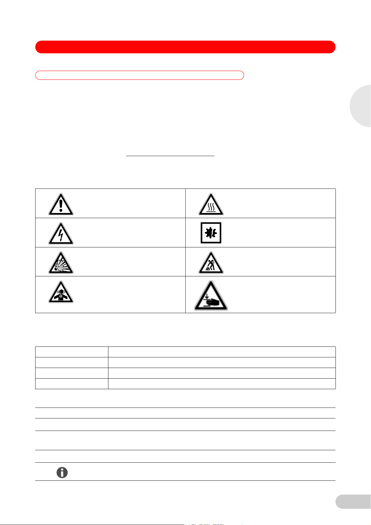
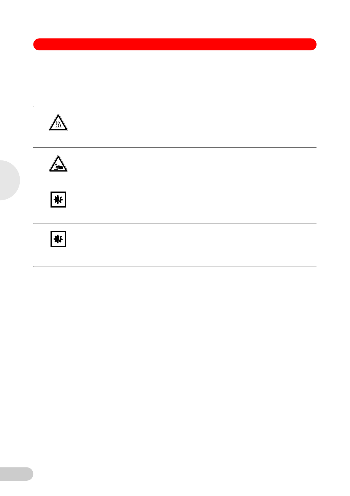
1.2.1 Hazard symbols
Hazard point Burns
Electric shock Material damage
.
1
Operating instructions
Explosion Heavy loads
Inhalation Crush
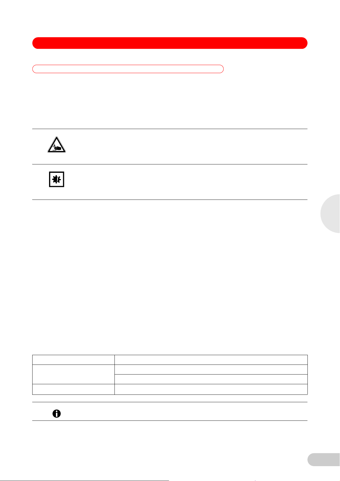
1.2.2 Degrees of danger
The following degree levels are used in safety messages throughout this manual. Acquaint
yourself with each item and the potential risk if you disregard the safety message.
DANGER Will lead to severe injuries or death.
WARNING May lead to severe injuries or death.
CAUTION May lead to light to moderate injuries.
NOTICE May lead to material damage.
1.3 Symbols used
Example Meaning
You are requested to perform an action.
1.
2.
• List.
Perform these actions in the sequence described.
References useful information.
5
Page 6

1
S41i CO2 Incubator Shaker — Operating manual
1.4 Abbreviations used
kWh Kilowatt hours
LEL Lower Explosion Limit
rpm Revolutions Per Minute
UEL Upper Explosion Limit
VA Volt Amps
VAC Voltage in Alternating Current
Operating instructions
6
Page 7
S41i CO2 Incubator Shaker — Operating manual
2 Product description
2 Product description
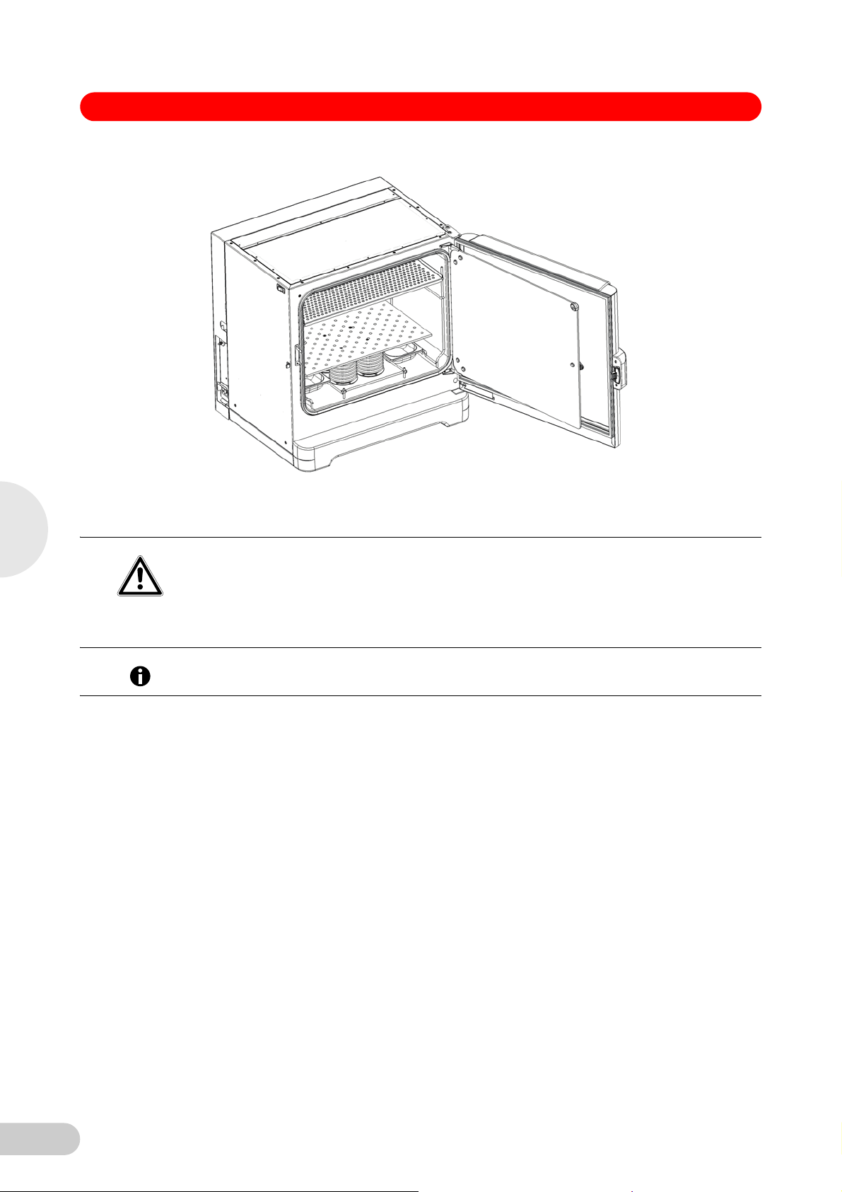
2.1 Main illustration
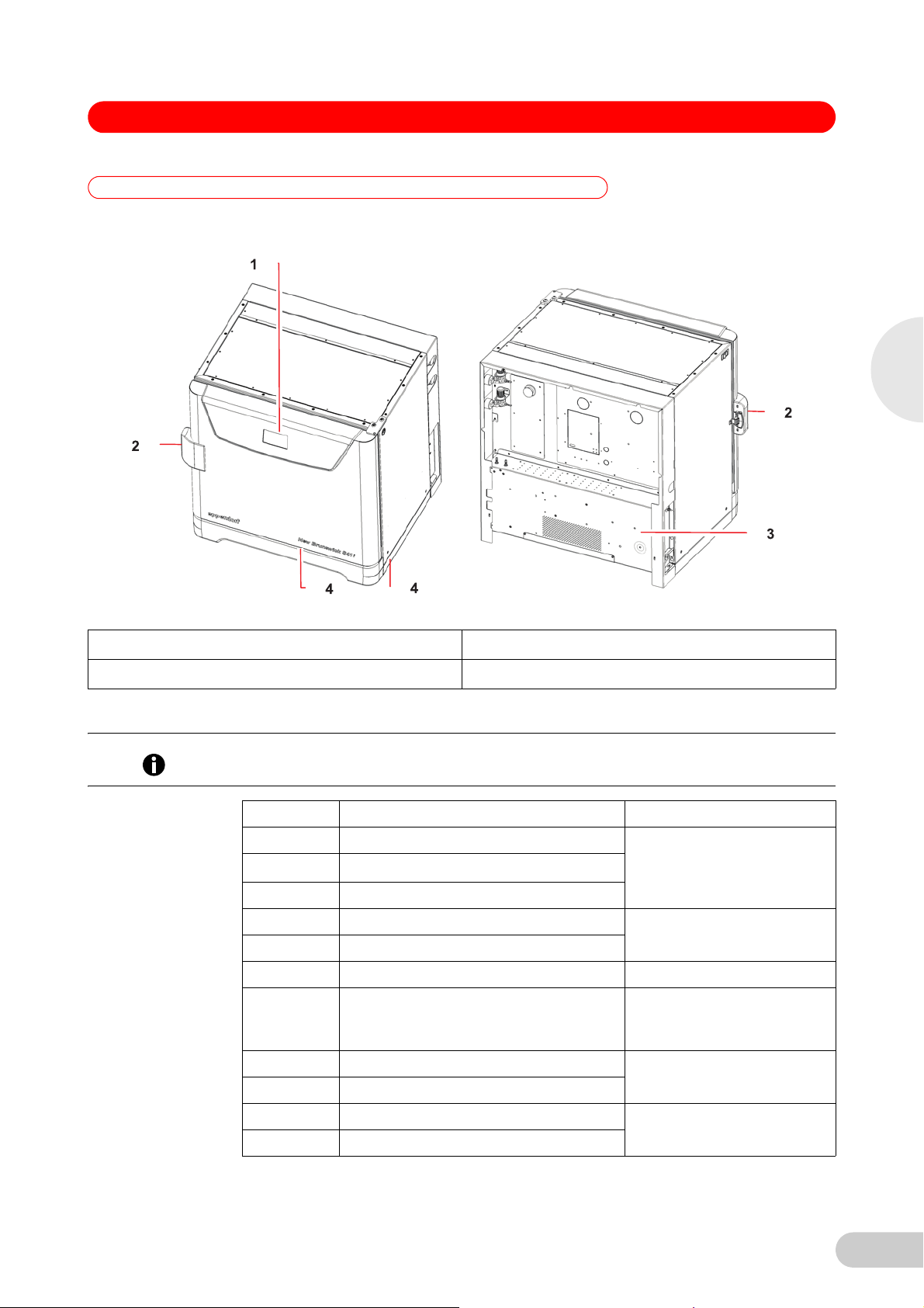
Abb. 1: Front and rear views
2
Product description
Fig. 1: Front and rear views
1 Display 3 Control box
2 Door handle 4 Foot shield
2.2 Delivery package
The operating manual and mains/power cord are shipped on top of the control box at the rear of
Hint!
the incubator/shaker.
Quantity Item Notes
1 Perforated Stainless Steel Shelf Installed
1 White porous CO
Sensor Cover
2
1 Black Sensor Cover
1 Front foot shield Packed on top of incubator/
2 Side foot shields
2 Humidity Trays Packed in box on shelf
3m(9.8ft) PVC Tubing, ~6mm(1/4in) bore, with an
inline CO
HEPA-filter connected, ready for
2
use
2 Hose Clips Packed in humidity tray
shaker
Packed in box on shelf
1 Auto-zero HEPA Filter
1 Mains/power Cord Packed on top of control box at
1 Operating Manual
rear of incubator/shaker
7
Page 8

2
S41i CO2 Incubator Shaker — Operating manual
Risk of silica particulates transferring to skin
Wear gloves anytime you touch the white CO
CAUTION!
Do not later touch those gloves to your face.
Discard or wash the gloves.
2.3 Features
The chamber’s fanless design with six-sided convection heating provides gentle circulation and
uniform temperature. In addition, the seamless one-piece chamber eliminates area where
contaminants could collect and makes wipe-down easy.
Two humidity trays reduce sample evaporation.
The New Brunswick S41i fits on the floor, on the floor under a work bench or it can be double
stacked to save space. The shaking mechanism is a heavy-duty drive with three eccentric drive
shafts to provide stability, uniform motion and assure long incubator/shaker life. The orbit is
2.5cm (1 in) and the shaking speed range is from 25-400rpm(±1rpm), unless two are
stacked, in which case the maximum speed of the top incubator/shaker is limited to 250rpm.
With no shelf present, flasks up to 4L in size can be installed on the shaking platform. With one
stationary shelf present, Erlenmeyer flasks up to 1L can be installed. If two shelves are present,
Erlenmeyer flasks, because of their tall necks, must be limited to 250mL.
The temperature range is from 4°C above ambient temperature to 50°C. Temperature accuracy
is ±0.2°C through the entire range.
Product description
CO2 control ranges from 0.2to20%, with an accuracy of ±0.1% at 20% CO2 via the InfraRed
CO2 sensor.
sensor cover.
2
8
Page 9
S41i CO2 Incubator Shaker — Operating manual
3 Safety
3Safety
3.1 Intended use
The New Brunswick S41i is half CO2 incubator and half biological shaker, combining the best
features of New Brunswick incubators and shakers into one versatile instrument. It provides
gas concentrations, enabling growth of
2
CAUTION!
gentle shaking and accurate control of temperature, CO
hybridomas, mammalian and stem cells, insect cultures, as well as aerobic and anaerobic
bacteria and yeast. A perforated stationary shelf is included for plates and T-flasks to enable
simultaneous incubation of adherent cultures.
The New Brunswick S41i was designed for controlled incubation and shaking of biological
samples. Do not use any heat-generating device inside the chamber.
Lack of safety due to incorrect accessories or spare parts
Accessories and spare parts that are not recommended by Eppendorf compromise the safety,
function and precision of the device. Eppendorf cannot be held liable or accept any liability for
damage resulting from the use of non-recommended accessories and spare parts.
Only use accessories and original spare parts recommended by Eppendorf.
3
When one shelf is installed, the largest flasks that can be contained in this incubator/shaker are 1
Hint!
L Erlenmeyer and 2.8 L Fernbach flasks. Without a shelf, Erlenmeyer flasks up to 4 L can be
contained.
3.2 Application limits
3.2.1 Description of ATEX Guideline (94/9EC)
Explosion hazard
Do not operate the device in areas where work is completed with explosive substances.
DANGER!
Do not use this device to process any explosive or highly reactive substances.
Do not use this device to process any substances which could create an explosive
atmosphere.
Due to its design and the ambient conditions in its interior, the device is not suitable for use in
potentially explosive atmospheres.
The device may only be used in a safe environment, e.g., the open atmosphere of a ventilated
lab.
The use of substances which may contribute to a potentially explosive atmosphere is not
permitted.
The final decision regarding the risks associated with using these types of substances is the
user's responsibility.
3.3 Information on product liability
Safety
In the following cases, the designated protection of the device may be compromised.
The liability for the function of the device passes to the operator if:
• The device is not used in accordance with this operating manual.
• The device is used outside of the range of application described in the succeding chapters.
• The device is used with accessories or consumables that were not approved by Eppendorf.
• Service or maintenance is completed on the device by people who are not authorized by
Eppendorf.
• The owner has made unauthorized modifications to the device.
9
Page 10
3
S41i CO2 Incubator Shaker — Operating manual
3.4 Warnings for intended use
Before using the incubator/shaker, read the operating manual and observe the following general
safety instructions.
3.4.1 Personal injury and damage to device
Risk of personal injury
Burns due to hot surface.
WARNING!
CAUTION!
NOTICE!
Do not touch the incubator/shaker during the high temperature disinfection cycle.
Do not open incubator/shaker door during the cycle.
Risk of personal injury
A mechanical lifting device is required to safely lift the incubator/shaker.
Risk of material damage
Never try to lift the incubator/shaker by its door; this would cause permanent damage to the
incubator/shaker.
Never lean on or place objects on the open door.
Safety
NOTICE!
Risk of material damage
To avoid possible damage to the CO
incubator/shaker is switched off, or when a high temperature disinfection cycle is initiated.
sensor, never leave water in the humidity trays while the
2
Allow a clearance of 50 mm (2 in) to allow access for oxygen sensor removal (optional
feature).
10
Page 11
S41i CO2 Incubator Shaker — Operating manual
4 Installation
4 Installation
4.1 Inspection of boxes
After you have received your order, inspect the boxes carefully for any damage that may have
occurred during shipping. Report any damage to the carrier and to your local Eppendorf
distributor immediately.
4.2 Unpacking
Risk of personal injury
A mechanical lifting device is required to safely lift the incubator/shaker.
CAUTION!
Risk of material damage
Never try to lift the incubator/shaker by its door; this would cause permanent damage to the
NOTICE!
incubator/shaker.
Never lean on or place objects on the open door.
Save the packing materials for possible future use, and be sure to save this Operating Manual
for instruction and reference. User manuals can also be found online, in PDF format, at
www.nbsc.com.
Save the foot shields packed on top of the incubator/shaker, which you will install.
Use a mechanical lifting device to safely lift the incubator/shaker off its shipping pallet and to
transport it to the installation site (see Location on p. 12). You may push the incubator/shaker
a short distance using the built-in castors to roll it. To do this, you may need to rotate the
incubator/shaker feet to raise them so the incubator/shaker will rest on its castors.
Remove the sleeved box sitting on the top shelf inside the incubator/shaker. As indicated in
Delivery package (see Delivery package on p. 7), It contains the two humidity trays, PVC
tubing and several other essential parts.
Remove the foam blocks from the top shelf and save them with the other packing materials.
Locate and remove the parts stored in the humidity trays.
Locate and unpack any other components.
If any part of your order was damaged during shipping, is missing, or fails to operate, please
contact your Eppendorf distributor.
Using your packing list, verify that you have received the correct materials, and that nothing is
missing.
4
Installation
4.3 Utilities requirements
The following utilities requirements are needed for operation:
Utility Requirement
Electricity 120V,50/60Hz earthed/grounded mains/electrical supply
230V,50/60Hz earthed/grounded mains/electrical supply
gas Cylinder with 100% CO2 vapor withdrawal
CO
2
CO2 gas pressure to device must exceed 7PSI (0.5bar) for optimal operation.
Hint!
11
Page 12
S41i CO2 Incubator Shaker — Operating manual
4.4 Location
The incubator/shaker is designed to operate at a chamber temperature of 4.0°C above ambient.
If the incubator/shaker is being operated at 37°C, the absolute minimum ambient temperature
recommended is 18°C. Maximum allowable ambient temperature is 25°C.
Position the incubator/shaker, allowing enough space to open the door and to access the CO2
Hint!
sample port on the right side of the incubator/shaker.
Care should be taken to avoid placing the incubator/shaker in a position that may affect its
performance, such as those listed below.
DO NOT place the incubator/shaker:
• Directly under, beside or within the air flow of heating or air-conditioning ducts, or other drafts
• Directly beside heat-generating equipment such as a heater, an autoclave or an oven
• Near the exhaust of heat- or cold-generating equipment (like an ultra-low temperature
freezer)
• Near a window exposed to direct sunlight
• Directly on top of any heat-generating apparatus
• Without minimum ventilation clearance of 10mm (0.5in) all around
4
Installation
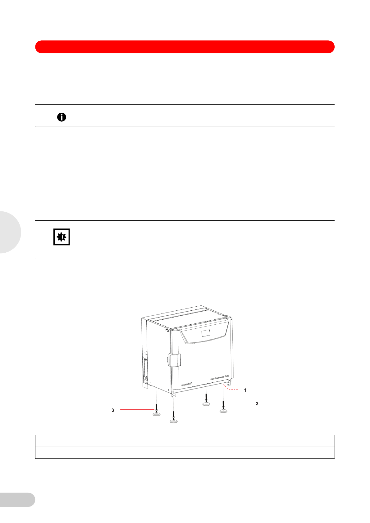
NOTICE!
Abb. 2: Adjustable feet
Risk of material damage
Never try to lift the incubator/shaker by its door; this would cause permanent damage to the
incubator/shaker.
Never lean on or place objects on the open door.
Remove the incubator/shaker from the pallet as described in Unpacking (see Unpacking on
p. 11).
Place the incubator/shaker in the working position, on a level floor capable of bearing its
weight. You may need to rotate the incubator/shaker feet to raise them, in order to rest the
incubator/shaker on its castors to be moved more easily (see Fig. 2 on p. 12).
Fig. 2: Adjustable feet
1 Castors located in all four corners 3 Lock nut
2 Adjustable foot
12
Page 13
S41i CO2 Incubator Shaker — Operating manual
The weight of the incubator/shaker is approximately 152kg(335lb), but actual in-use weight will
naturally be heavier and will depend on both the options installed and the material stored in the
incubator/shaker.
The incubator/shaker is designed so that one incubator/shaker can be safely stacked on top of
another S41i using the optional stacking kit, which includes instructions. It is not possible to put
any other type of incubator/shaker or heavy apparatus on top, as the top cover and stacking kit
are designed to support only the feet of another S41i.
4.5 Installation of foot shields
The front and side foot shields (see Fig. 3 on p. 13) are packed on top of the incubator/shaker,
enclosed in bubble wrap. To install them, beginning with the right side foot shield, follow this
procedure:
1. Orient the mounting bracket at the front face of the incubator/shaker, then align the foot
Abb. 3: Front and side foot shields
shield’s two keyhole slots with the two mounting pins on the bottom of the incubator/shaker.
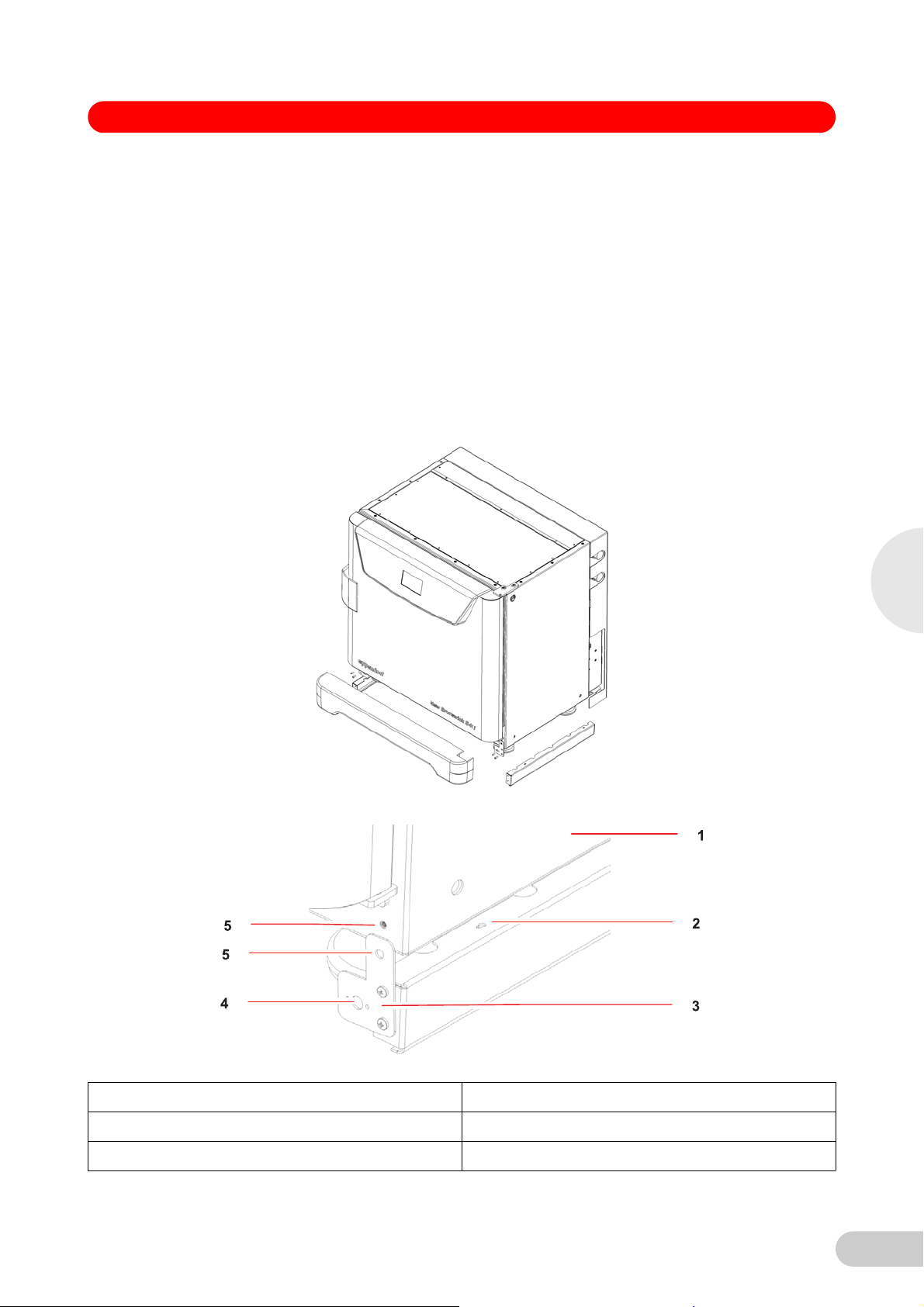
Fig. 3: Front and side foot shields
Abb. 4: Side foot sh ield installation
4
Installation
Fig. 4: Side foot shield installation
1 Right side of incubator/shaker 4 Hole for front foot shield’s ball catch
2 Keyhole slot on right side foot shield 5 Hole for M4 screw
3 Mounting bracket
13
Page 14
4
S41i CO2 Incubator Shaker — Operating manual
2. Snap the side shield in place, then slide it toward the back of the incubator/shaker until the
bracket is flush against the front face.
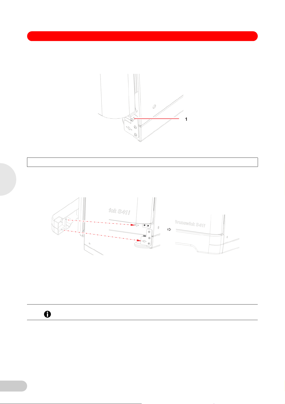
3. Fasten the bracket to the incubator/shaker with one M4 screw:
Abb. 5: Side foot sh ield bracket
Fig. 5: Side foot shield bracket
1 M4 screw inserted here to fasten the side foot shield bracket to the incubator/shaker
4. Repeat Steps 1 through 3 for the left side foot shield.
5. Push fit the remaining foot shield onto the bottom front of the incubator/shaker. Be sure to
align its pins with the holes on the incubator/shaker and on the mounting brackets of the side
foot shields.
Abb. 6: Front foot shield installation
Installation
Fig. 6: Front foot shield installation
4.6 Platform assemblies
4.7 Installation of platform
A platform, which is required for operation, is a separate item, not included with the shaker
assembly. The S41i platform, measuring 612×356mm(24×14in), will accept a wide range of
clamps for flasks, test tubes, etc.
Prior to use, a platform must be installed on the incubator/shaker.
Hint!
The incubator/shaker is shipped with four Allen head platform screws installed in the four bearing
housing uprights, as shown below:
14
Page 15
S41i CO2 Incubator Shaker — Operating manual
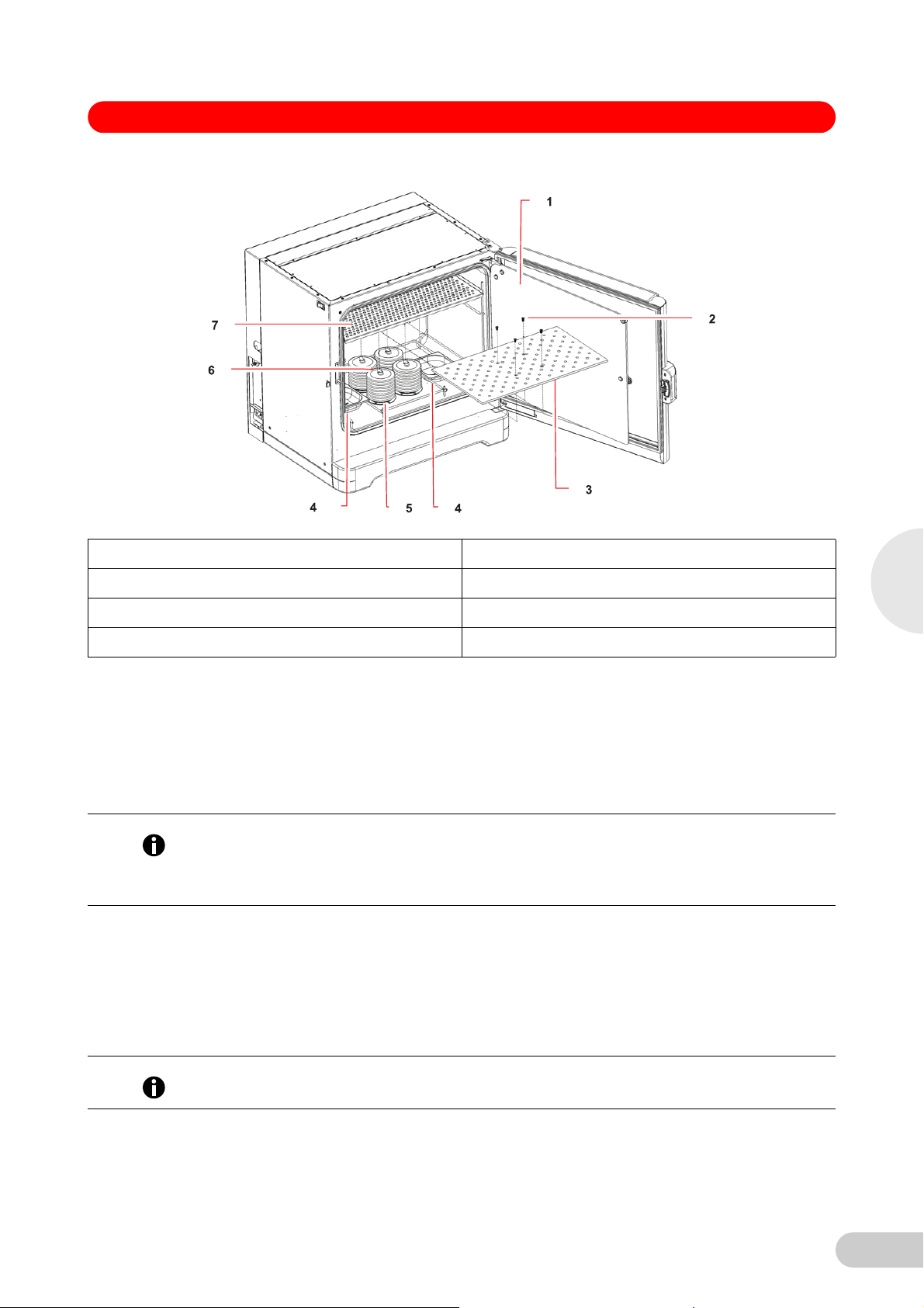
Abb. 7: Installing plat form
Fig. 7: Installing platform
1 Glass inner door 5 Bearing housing
2 Allen screws 6 Bearing housing uprights
3 Platform 7 Top shelf, shipped installed
4Humidity trays
1. Set the mains/power to OFF and unplug the incubator/shaker.
2. Remove the platform screws, then use them to install the platform over the bearing housing.
4.8 Flask clamp installation
Flask clamps purchased for use with the platform require installation. Clamps are installed by
securing the base of the clamp to the platform with the correct type and number of screws. All
clamps are shipped complete with hardware.
The S41i platform requires 10-24×5/16-inch Phillips-head screws (which are supplied) to fasten
Hint!
flask clamps.
With one shelf installed, Erlenmeyer flasks larger than 1L are too tall for the chamber; to use
2L–4L Erlenmeyer flasks, remove the shelf.
Clamps for 2.8-liter Fernbach flasks and 2L–4L Erlenmeyer flasks are shipped with an
additional girdle to keep the flasks in place. The girdle is an assembly of springs and sections of
rubber tubing. One girdle is already in place on the clamp, the other is packed separately.
To install these double girdle clamps:
1. Place the clamp on the platform, aligning its mounting holes with holes on the platform.
Secure the clamp in place using the flat Phillips head screws provided
(#S2116-3051,10-24x5/16-inch).
4
Installation
Three different types of screws are shipped with the clamps, to identify the proper screws
Hint!
(see Fig. 8 on p. 16).
2. With the first girdle in place, as delivered, on the upper part of the clamp body, insert an
empty flask into the clamp.
15
Page 16
S41i CO2 Incubator Shaker — Operating manual
3. After making sure the sections of tubing are located between the clamp legs, roll the first
girdle down the legs of the clamp as far as it can go. The tubing sections will rest against the
platform, and the springs will be under the clamp base.
4. Place the second girdle around the upper portion of clamp body (just as the first girdle was
initially). Make sure that its spring sections rest against the clamp legs, while its rubber tubing
sections sit against the flask, in between the clamp legs.
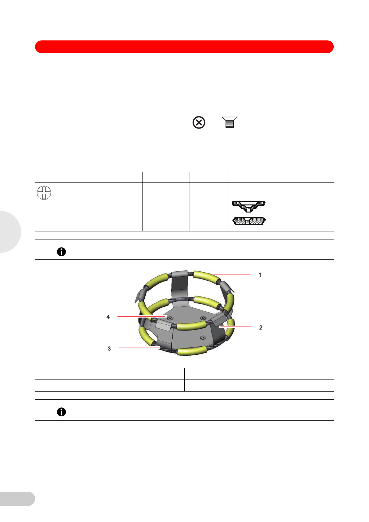
Abb. 8: Clamp fastener
Fig. 8: Clamp fastener
New Brunswick flask clamps are used on a variety of incubator/shaker platforms. Flat head
screws of different lengths and thread pitch are used to secure the clamp. The following table
identifies the proper screw for your incubator/shaker application by reference to the head style.
Select the appropriate screws and set the others aside.
Description Part number Qty Application
S2116-3051 1 5/16"(7.9mm) thick aluminum, phenolic
10-24×5/16(7.9mm) flat Phillips
(+) head screw
and stainless steel platforms.
4
Installation
One-liter and larger flask clamps are fastened with 5 screws.
Hint!
Abb. 9: Double gird le clamp installatio n
Fig. 9: Double girdle clamp installation
1 Upper girdle with girdle tubes 3 Lower girdle with girdle tubes
2 Clamp body (legs and base) 4 Clamp mounting holes (quantity:5)
The upper girdle secures the flask within the clamp, and the bottom girdle keeps the flask from
Hint!
spinning.
4.9 Stacking instructions
16
To stack two S41i incubator shakers, you must first have purchased the stacking kit. You will find
the instructions contained in the kit.
Page 17
S41i CO2 Incubator Shaker — Operating manual
4.10 Electrical connections
Risk of electrical hazard
Before making electrical connections, be sure to check the following list.
CAUTION!
1. If you have not already done so, check that the voltage and frequency of your incubator/
shaker are compatible with your mains/electric supply.
2. Set the circuit breaker on the left side of the incubator/shaker to the OFF position.
ONLY THEN:
Risk of material damage
An earthed/grounded electrical outlet is necessary for the safe operation of this instrument.
NOTICE!
3. Plug the mains/power cord into an earthed/grounded electrical outlet.
4.11 Setting up
1. If necessary, level the incubator/shaker by adjusting the feet, after removing the foot shields.
Place a small level on the shelf of the incubator/shaker. Adjust the leveling feet until the
incubator/shaker is level and stable. Lock the leveling feet in place by tightening the locking
nuts on each foot. Reinstall the foot shields.
2. Fill each humidity tray halfway with water (approximately 250mL) if you wish to use them for
humidification.
4
Installation
Hint!
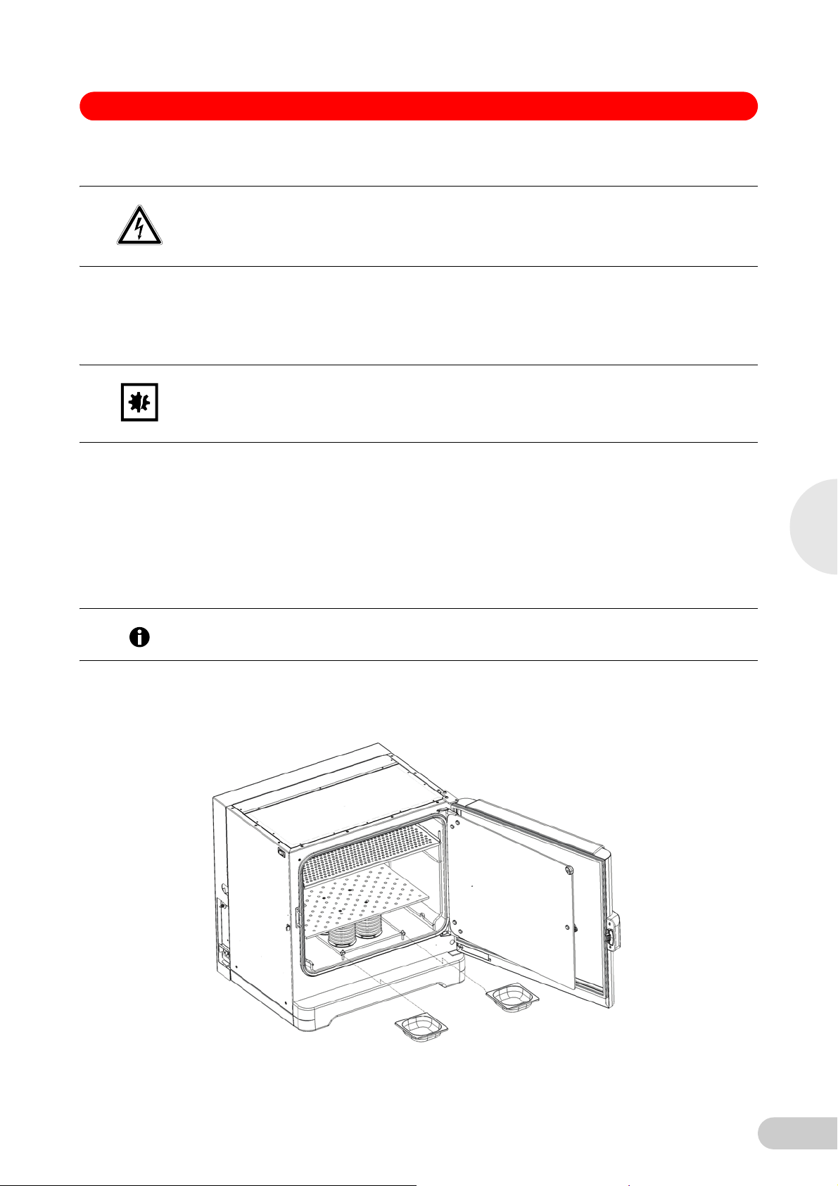
Abb. 10: Installing the humidity trays
Be sure to install the humidity trays one at a time, after wiping the bottom and edges dry.
If you will not use them for humidification, install them anyway to catch spills.
3. Place the humidity trays one at a time onto the parallel support rods on either side of the
bearing housing at the bottom of the incubator/shaker. Sit them behind the stopper bends,
making sure that the back edge of each tray fits under the end of the condensation/spill
channel.
Fig. 10: Installing the humidity trays
17
Page 18
4
S41i CO2 Incubator Shaker — Operating manual
Abb. 11: Humidity trays, installed
Fig. 11: Humidity trays, installed
4.12 Making connections
Risk of explosion
Use gases in this equipment only within the range between their lower explosion limit (LEL)
WARNING!
and their upper explosion limit (UEL).
If your process requires or produces gases, be sure to verify their LEL and UEL concentration
range (available online or ask your gas supplier).
Installation
In-line regulators are provided on the back of the incubator/shaker. These are essential to proper
Hint!
operation.
1. Connect the incubator/shaker to the CO2 supply using the ~6mm plastic tubing (with
installed HEPA filter) by attaching the tubing from the supply to the top regulator inlet on the
back of the incubator/shaker. The bottom regulator inlet is reserved for N2 if your incubator/
shaker is equipped with the oxygen control option.
18
Page 19
S41i CO2 Incubator Shaker — Operating manual
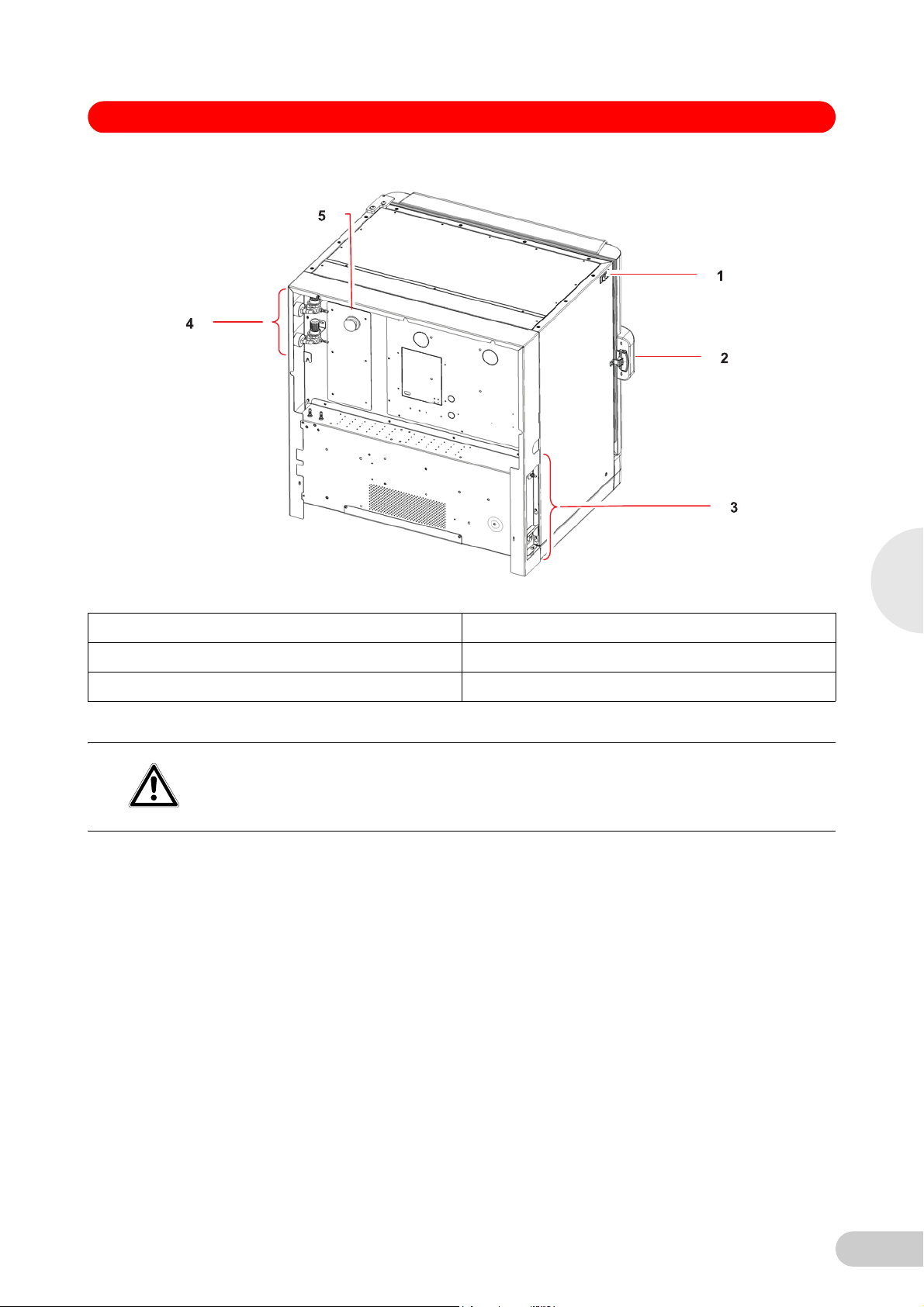
Abb. 12: Rear view (back panel rem oved)
Fig. 12: Rear view (back panel removed)
1 ON/OFF switch 4 Inline gas regulators (access from the side)
2 Door handle 5 Access port
3 See Control box (right side) figure for details.
2. Use the tubing clips provided to eliminate CO
Risk of electrical hazard
leaks.
2
Before making electrical connections, verify that your mains/power supply voltage matches
WARNING!
the voltage of your incubator/shaker and that the on/off switch is in the OFF position.
3. Plug the mains/power cord into its receptacle on the right side of the control box.
4. After verifying that your supply voltage matches the voltage specified for your incubator/
shaker and that the ON/OFF switch is OFF, plug the cord into your mains/power supply outlet.
5. Press the Auto-Zero HEPA filter gently into the white plastic filter socket on the right side of
the control box.
4
Installation
19
Page 20
S41i CO2 Incubator Shaker — Operating manual
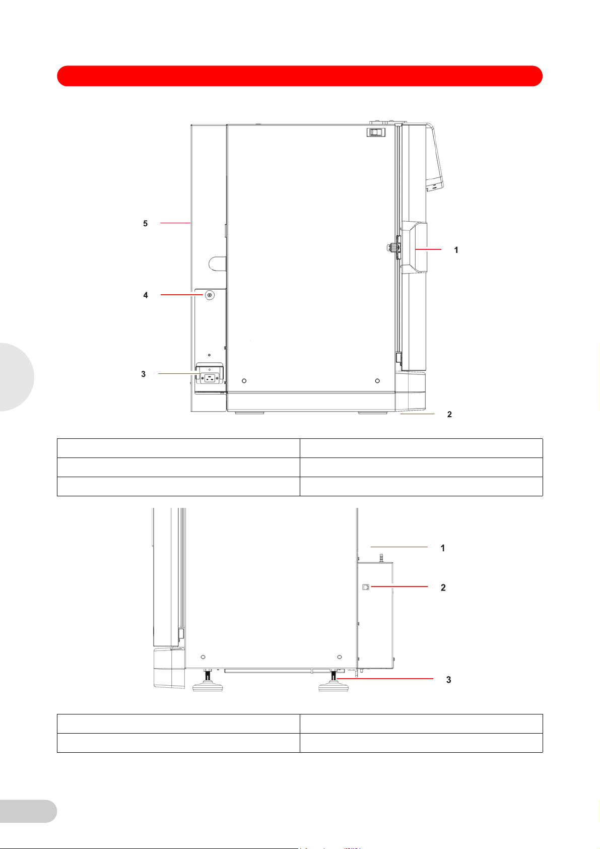
Abb. 13: Control box (right side)
4
Installation
Fig. 13: Control box (right side)
1 Door handle 4 Auto Zero filter socket
2 Adjustable foot (shown with side shield) 5 Back panel in place
3 Mains/power receptacle
Abb. 14: Control box (left side)
Fig. 14: Control box (left side)
1 (Shown with back panel removed) 3 Adjustable foot (shown without side shield)
2 Ethernet connection
20
Page 21

S41i CO2 Incubator Shaker — Operating manual
4.13 Ethernet connection
The ethernet connection is provided as a connection to a personal computer on which you can
run New Brunswick BioCommand
from its operation. Speak to your sales representative for information about this program.
®
SFI software to control the incubator/shaker and log data
4
Installation
21
Page 22
5
Operation
S41i CO2 Incubator Shaker — Operating manual
5 Operation
5 Operation
5.1 Preparing for operation
1. Remove the black protective cover from the CO2 sensor, and store it in a safe place. The
sensor cap should be placed back on the sensor when the incubator/shaker is to be cleaned.
2. Ensure that the white porous sensor cover remains in place.
Risk of silica particulates transferring to skin
CAUTION!
Wear gloves anytime you touch the white CO
Do not later touch those gloves to your face.
Discard or wash the gloves.
3. Using the mains/power cord provided, connect the incubator/shaker to a earthed/grounded
mains/power supply.
4. Switch the incubator/shaker ON using the on/off switch at the top left side of the incubator/
shaker.
The display will illuminate immediately.
sensor cover.
2
5. Turn on the CO
6. The chamber setpoints are pre-programmed at 37.0°C and 5% CO
shaker on until the programmed chamber temperature and CO2 concentration have been
reached.
• The incubator shaker’s CO
Hint!
temperature setpoint. After the temperature setpoint is reached, the CO
allowing the incubator/shaker to reach the CO2 setpoint.
• If mains/power is interrupted to the incubator/shaker long enough for the temperature to drop
below setpoint, the CO
(This serves to avoid spurious CO2 readings while the incubator/shaker is below its
temperature setpoint)
7. Leave the incubator/shaker running overnight to allow conditions to stabilize.
5.2 Using the humidity trays
If humidification is required, each of the two humidity trays should be filled with approximately
250mL of warm (~37.0°C) distilled water at this time.
Risk of material damage
To avoid possible damage to the CO
NOTICE!
incubator/shaker is switched off, or when a high temperature disinfection cycle is initiated.
Allow a clearance of 50 mm (2 in) to allow access for oxygen sensor removal (optional
feature).
gas supply with the pressure regulator set to 7 PSI (0.5 bar).
2
. Leave the incubator/
2
valve is disabled until the incubator/shaker reaches the
2
valve will be deactivated until temperature setpoint is again achieved.
2
sensor, never leave water in the humidity trays while the
2
valve is activated,
2
The humidity level within the chamber is not adjustable. The internal chamber will reach between
85 and 95% relative humidity at 37°C (depending on ambient humidity) using the humidity
trays.
5.3 Starting the incubator/shaker
The incubator/shaker will not operate if the door is open.
Hint!
To initially start the incubator/shaker, close the door, make sure the incubator/shaker’s mains/
power cord is securely plugged in, and turn the mains/power switch (located on the top left side of
the instrument) to the ON (I) position.
22
Page 23

S41i CO2 Incubator Shaker — Operating manual
The initial display will come on for a few moments, then you will see the STATUS screen
(see Preparing for operation on p. 22).
In the unlikely event that the audible alarm sounds upon start-up, a yellow ALARM screen will
appear, prompting you to mute and to acknowledge the alarm:
1. Press the Mute button in the screen to silence the audible alarm.
2. If you have Administrator status (see USER ACCESS screen on p. 43), follow the instructions
to acknowledge the alarm; if you have User status, get an Administrator to acknowledge the
alarm.
3. Use the LEFT and RIGHT arrow buttons to see if there are any other alarms to acknowledge.
4. If any alarms continue to be unacknowledged, there will be a yellow star behind the ALARM
icon in the STATUS and SUMMARY screen until the alarm is acknowledged.
5. After acknowledgement, the reason for any alarm should be tended to and rectified. For
details on using alarms (see ALARM SETTINGS screen on p. 30).
5.4 Using the touchscreen
5.4.1 Initial display and STATUS screen
This is the first screen you will see when you turn the incubator/shaker ON:
This is a sample screen, the version number shown will vary.
Hint!
5
Operation
1 The yellow smiling icon in the upper lefthand corner of each screen indicates that
the software is working. If at any time you see a red frowning icon, the software is
not working and will require troubleshooting.
The initial screen will remain displayed for a few moments, then change to the STATUS screen:
23
Page 24

5
Operation
S41i CO2 Incubator Shaker — Operating manual
If the display showed the SUMMARY screen when it was powered off, when you restart, the
Hint!
SUMMARY screen (see SUMMARY screen on p. 32) will appear instead of the STATUS screen.
You may need to calibrate the touchscreen to your touch (see SET CALIBRATION screen on
p. 36).
O2 option not available.
5.4.2 Starting the platform
The STATUS or SUMMARY screen will display a START button to launch operation of the
incubator/shaker platform. The START button changes to a STOP button when pressed.
1. Press START from STATUS or SUMMARY screen.
The confirmation screen appears.
If the ALARM icon appears, an alarm condition exists. This needs to be
acknowledged and rectified. Go to the ALARMS screen (see ALARM
SETTINGS screen on p. 30).
The presence of the open LOCK icon indicates that the user screens are
unlocked for access to make changes. When the padlock is closed, the
screens are locked against changes; Admin level security is required to
make edits.
24
Page 25

S41i CO2 Incubator Shaker — Operating manual
2. Press YES to start the incubator/shaker platform.
The STATUS or SUMMARY screen displays the STOP button.
5
Operation
O2 option not available.
Hint!
5.4.3 Setting the temperature
At any time you can press the °C line in the STATUS screen to open the Temperature Range
screen, which allows you to set temperature parameters:
25
Page 26

5
Operation
S41i CO2 Incubator Shaker — Operating manual
Press the High Alarm line and use the popup keypad to set the temperature at which an alarm
will alert you to the temperature rising too high.
Press the Low Alarm line and use the popup keypad to set the temperature at which an alarm
will alert you to the temperature falling too low.
Press the Setpoint line and use the popup keypad to set the desired working temperature.
5.4.4 Setting the CO
level
2
At any time you can press the CO
which allows you to set parameters for carbon dioxide in the chamber:
line in the STATUS screen to open the CO2 Range screen,
2
Press the High Alarm line and use the popup keypad to set the percentage at which an alarm
will alert you to the CO
level rising too high.
2
Press the Low Alarm line and use the popup keypad to set the temperature at which an alarm
will alert you to the CO2 level falling too low.
Press the Setpoiint line and use the popup keypad to set the desired percentage of CO
chamber.
in the
2
5.4.5 Setting the shaking speed
26
At any time you can press the RPM line in the STATUS screen to open the Speed Range screen,
which allows you to set parameters for the shaking speed and run time:
Page 27

S41i CO2 Incubator Shaker — Operating manual
Press the High Alarm line and use the popup keypad to set the speed at which an alarm will
alert you to the rpm rising too high.
Press the Low Alarm line and use the popup keypad to set the speed at which an alarm will
alert you to the rpm level falling too low.
Press the Setpoint line and use the popup keypad to set the desired shaking speed.
Press the Set Hours line to set the number of hours of shaking you wish to program, using the
popup keypad.
Do the same to Set Minutes.
After you program the Hours and Minutes of the run time and then press OK the button to
return to the STATUS screen.
Now there will be a STOPWATCH icon next to RPM, to indicate that the countdown of Run
Time has been enabled:
5
Operation
5.4.6 % RH
Hint!
If your New Brunswick S41i is not equipped with an optional humidity sensor, the STATUS screen
will not display %RH.
If your New Brunswick S41i is equipped with an optional humidity sensor, the STATUS screen will
show %RH (relative humidity) at the bottom of the screen:
O2 option not available.
This is a current reading; you cannot program any setpoints or alarms.
27
Page 28

5
Operation
S41i CO2 Incubator Shaker — Operating manual
5.5 MENU 1 screen
Press MENU button to open the first of two MENU screens:
Hint!
5.5.1 HELP function
5.5.2 EVENT LOG
Press the Status View button or DONE button at any time to return to the main STATUS View
screen.
When you press the DONE button in the MENU screen's , if you had previously been viewing the
SUMMARY screen, the system will return you to the SUMMARY screen.
Whenever there is a HELP button in a screen, you can press it at any time to find additional
information regarding the screen you are viewing.
Abb. 15: Event log button
Fig. 15: Event log button
In the first MENU screen, press the Event Log button to open the EVENT LOG:
28
Page 29

S41i CO2 Incubator Shaker — Operating manual
Press any of the events listed in this screen to open an EVENT DETAIL SCREEN, then press
the DONE button to return to the EVENT LOG screen.
To c l e ar th e EVENT LOG screen, press the CLEAR button; you will be prompted to confirm
your choice with this screen:
5
Operation
Press the YES button to clear the log; press the NO button to return to the EVENT LOG
screen without making changes.
Press the EXPORT button to save event log data to a USB memory stick/flash drive. You will
be prompted with the following screen:
29
Page 30

5
Operation
S41i CO2 Incubator Shaker — Operating manual
Insert the memory stick/flash drive in the USB port located under the touchscreen, then press
the START button.
In the EVENT LOG screen you can also press the LEFT or RIGHT button to view previous or
additional EVENT data screens.
Press the DONE button to return to MENU.
5.5.3 ALARM SETTINGS screen
Abb. 16: Alarms button
Fig. 16: Alarms button
Press the ALARMS button in the MENU 1 screen to open the ALARM SETTINGS screen:
30
The Audible alarm is either ON or OFF, whichever is highlighted in your screen (it is ON in the
sample screen above). To change its status, press anywhere in this line except where it is
already highlighted, and it will automatically change.
Page 31

S41i CO2 Incubator Shaker — Operating manual
If an audible alarm is triggered:
Mute and acknowledge alarm (see Starting the incubator/shaker on p. 22), and rectify the
condition that triggered the alarm.
When the door is opened, an alarm is displayed and logged. To delay the triggering of the
open door alarm:
Press anywhere in the Door Delay Seconds line.
In the SET DOOR DELAY SECONDS keypad that opens:
5
Operation
Use the keys to enter the desired delay in seconds, then press the OK button to save the
value. You will return to the ALARM SETTINGS screen and your value will be displayed.
If you wish to test the alarms:
press the TEST button to open the ALARM TEST screen:
The test will begin automatically with the opening of this screen. You should see a
yellowcolored screen with red lettering at the top, symbolizing a visual alarm, and you should
hear an audio alarm.
Press DONE button to acknowledge the test and to stop the audio alarm.
Press the OK button in the ALARM SETTINGS screen at any time to return to the MENU
screen.
31
Page 32

5
S41i CO2 Incubator Shaker — Operating manual
5.5.4 SUMMARY screen
Abb. 17: Summary view button
Fig. 17: Summary view button
Operation
Press the Summary View button to open the SUMMARY screen.
If your incubator/shaker is not equipped with a humidity sensor, your SUMMARY screen will not
Hint!
indicate RH (Relative Humidity).
O2 option not available.
Like the STATUS screen, the SUMMARY screen has a START button which, once it has been
pressed to launch operation, becomes a STOP button to allow you to stop operation.
If the icon appears, an alarm condition exists. This needs to be acknowledged and rectified.
Go to the ALARMS screen (see ALARM SETTINGS screen on p. 30).
The presence of the open LOCK icon indicates that the user screens are unlocked for access
to make changes. When the padlock is closed, the screens are locked against changes;
Admin level security is required to make edits.
The following table identifies the five values (parameters) that may appear in abbreviated
form in the lefthand column of the SUMMARY screen:
Abbreviation Value
Temp Temperature (°C)
CO
2
RPM Shaking speed (rpm)
RH Relative Humidity (%)
As with the STATUS screen, press any Setpoint to open that parameter’s screen to set or
reset the Setpoint.
When you set a Run Time, the STOPWATCH icon appears next to RPM in the SUMMARY
screen, too:
Carbon Dioxide (%)
32
Page 33

S41i CO2 Incubator Shaker — Operating manual
O2 option not available.
Hint!
5.5.5 EVENT GRAPH screen
Abb. 18: Event graph button
5
Operation
Fig. 18: Event graph button
Press the Event Graph button to open the EVENT GRAPH screen:
O2 option not available.
Hint!
If you press the HELP button, the following screen will appear:
33
Page 34

5
Operation
S41i CO2 Incubator Shaker — Operating manual
The BACK button returns you to the MENU screen.
Press any parameter's graph line to open that particular graph.
Although the following example shows a Relative Humidity (RH) graph, note that this parameter
Hint!
will not be mapped in the Events Graph if your system is not equipped with an optional humidity
sensor.
Click anywhere along the Y (vertical) axis to open a Span popup screen that allows you to
change the scale of this axis:
34
Page 35

S41i CO2 Incubator Shaker — Operating manual
The current view shows from 0.0% to 25.0%. If you press, for example, 10% RH then press
the DONE button, the Relative Humidity Graph X axis will change to display a scale from
0.0% to 10.0%.
5
Operation
Press anywhere along the X axis to open a Time Span popup screen:
35
Page 36

5
Operation
S41i CO2 Incubator Shaker — Operating manual
Press any selection, “3 Days” for example, then press the DONE button. The Relative
Humidity Graph X-axis will now show a time span of 3 days onscreen, between the 1st marker
on the left and the 3
At any time, you can use the UP and DOWN arrow buttons to scroll through values, and use
the LEFT and RIGHT arrow buttons to scroll through Time.
rd
on the right.
5.5.6 SET CALIBRATION screen
Abb. 19: Calibrate button
Fig. 19: Calibrate button
Press Calibrate button to open the SET CALIBRATION screen:
36
The following sections explain the options offered in this screen.
Page 37

S41i CO2 Incubator Shaker — Operating manual
Agitation gain
If you measure the shaking speed (“Actual Speed”) with a tachometer and find that it does not
match the speed displayed in the STATUS and SUMMARY screens (“Indicated Speed”), proceed
as follows:
1. Let the unit arrive at the desired shaking speed, then record the Indicated Speed from the
display.
2. Use a tachometer to measure the speed and record the Actual Speed.
3. Calculate the Speed correction value using this formula:
Actual Speed – Indicated Speed = Agitation Gain Value.
4. In the SET CALIBRATION screen, press anywhere in the Agitation Gain line. This screen will
open:
5
Operation
5. When the speed stabilizes, press the OK button. This screen will open:
No setpoint or agitation gain below 100rpm or above 400rpm can be entered.
Hint!
6. Use the keypad to enter the RPM as you measured it, then press the OK button to save the
value.
This allows the system to recalibrate agitation speed.
37
Page 38

5
Operation
S41i CO2 Incubator Shaker — Operating manual
Calibrate touchscreen
To calibrate the touchscreen, press Calibrate Touchscreen and follow the instructions in the
screen that opens. You will be prompted to touch the screen at several locations.
When the calibration has been completed, the system will return to the SET CALIBRATION
screen.
Press the OK button to return to the MENU.
5.5.7 GENERAL SETTINGS screen
Abb. 20: General settings button
Fig. 20: General settings button
Press the General Settings button to open the GENERAL SETTINGS screen:
38
The Power Save Brightness setting governs the degree of brightness or dimness that you
see onscreen when the screen engters Power Save mode.
Click inside the Power Save Brightness bar to move the light blue marker to any of 5 choices
ranging between Min and Max.
Page 39

S41i CO2 Incubator Shaker — Operating manual
This sample screen shows the marker moved from Min, where it was previously, to midrange:
The Power Saver Timeout is the time after which, if the display remains untouched, the
screen will dim.
5
Operation
Press Power Saver Timeout to set or reset the timeout duration. In the SET POWER SAVE
MINUTES keypad screen that opens:
Input the desired number of minutes, then press OK.
If Security is not enabled (the check box is empty, as shown in sample GENERAL
SETTINGS screen), press Security or press inside the checkbox to enable it:
39
Page 40

5
Operation
S41i CO2 Incubator Shaker — Operating manual
If you do not have Administrative authority, you will see this screen:
Press the OK button to acknowledge this message to return to the GENERAL SETTINGS
screen.
When Security is enabled, the padlock icon on the SUMMARY and STATUS screens will be
Hint!
closed, and users will have access to only the SUMMARY and STATUS screens. In fact, the
MENU button in the SUMMARY screen will have changed to a VIEW button.
The Lock Timeout is the time of screen idling after which, when Security is enabled, the
system will lock itself. The padlock will change from unlocked to locked and a user with
Administrative privileges (see USER ACCESS screen on p. 43) must log on to unlock the
system.
Press Lock Timeout to set or change the duration.
In the SET LOCK TIME MINUTES keypad that opens, press the keys to input the desired
time, then press the OK button:
40
When you return to the GENERAL SETTINGS screen, press the RIGHT arrow button to open
the next GENERAL SETTINGS screen:
Page 41

S41i CO2 Incubator Shaker — Operating manual
In the above example, the display is set to 24-hour (military) time. If you press the Format line,
it will automatically toggle to 12-Hour:
5
Operation
To change from PM (highlighted) to AM, press AM.
To change the Hours, press either Hours or the number (2 in this case) and use the popup
keypad to update the hour, then press the OK button to save your update.
To change the Minutes, press either Minutes or the number (18 in this case) and use the
popup keypad to update the hour, then press the OK button to save your update.
Press the RIGHT arrow button to open the next GENERAL SETTINGS screen:
41
Page 42

5
Operation
S41i CO2 Incubator Shaker — Operating manual
Press Day, Month and/or Year and use the popup keypad in each case to correct the date,
which is displayed in the upper righthand corner of the screen.
To change the Format of the date (shown in European style), press anywhere in the Format
line to open the SET FORMAT screen:
42
Press the date format you prefer, for example June 16, then press the OK button to return to
the date settings screen. Note that the date format in the top right corner has changed:
Page 43

S41i CO2 Incubator Shaker — Operating manual
After you have made all desired changes to the settings, press the DONE button to return to
the MENU.
5
Operation
5.5.8 USER ACCESS screen
Abb. 21: Users button
Fig. 21: Users button
Press the Users button to open the USER ACCESS screen:
Press the NEW button to add a User. In the NEW USER NAME keypad:
43
Page 44

5
Operation
S41i CO2 Incubator Shaker — Operating manual
Use the keypad to choose numbers and/or letters. For buttons with one number and several
letters, you will need to press repeatedly to input the desired character (they appear in
sequence; for example, press 2, ABC button once to display 2 in the edit field; a second time
to display A; press it again for B; and a fourth time for C. If you press it again, it will cycle back
to 2.
Move to the next key to input the next number or letter.
A user name may be up to 8 characters in length.
Hint!
If you need two or more items from the same key, wait a few seconds after selecting the first, then
press the key again as needed to select the next item.
In this sample screen, we pressed the 3, DEF key three times to cycle through 3, then D, to E:
When the User Name is complete, press the NEXT button. The name will be saved, and the
NEW PASSWORD keypad will open:
44
Page 45

S41i CO2 Incubator Shaker — Operating manual
The keys work the same way here as in the NEW USER NAME screen.
When the desired Password is in the field, press the OK button to save it for the new user and
to return to the USER ACCESS screen.
If the Password is inappropriate (for example, too short), you will be prompted with an
ILLEGAL PASSWORD warning screen:
5
Operation
Press the OK button to return to the NEW PASSWORD keypad and input an appropriate
password.
When the desired Password is in the field, press the OK button to save it for the new user and
to return to the USER ACCESS screen.
You may need to set privileges for one or more users:
Press the user’s name to highlight that row, then press the EDIT button to open the EDIT
USER screen:
45
Page 46

5
Operation
S41i CO2 Incubator Shaker — Operating manual
Press Name: to open the CHANGE USER NAME screen, make changes, then press the OK
button to return to the USER ACCESS screen.
To make more edits to this or any other user’s information, press the user’s name to highlight
the row, then press the EDIT button.
PAS SWORD screen; press the YES or NO for Setpoint Access and/or Admin Access to
select the desired settings, then press the OK button to return to the USER ACCESS screen.
Setpoint Access gives the user access to edit setpoints.
Hint!
Admin Access allows access to all user functions.
To remove a user from the system:
Highlight the name, press the DELETE button, then press the OK button. You will be prompted
to indicate whether you are sure about this deletion:
46
Press the YES or NO button as appropriate. You will return to the USER ACCESS screen.
Press the DONE button when you have finished to return to the MENU screen.
Page 47

S41i CO2 Incubator Shaker — Operating manual
5.5.9 COMMUNICATIONS screen
Abb. 22: Communications button
Fig. 22: Communications button
Press Communications button to open the SET COMMUNICATIONS screen:
5
Operation
Ethernet is the default mode, which is why the IP Address is displayed.
If you need to change the IP address
press that line to open a keypad for the first three digits:
Use the OK button either to reset each of the four sets of digits (Address A, B, C and D) or to
cycle through each set and change any as needed.
Press the button in the SET COMMUNICATIONS screen at any time to return to the MENU
screen.
47
Page 48

5
Operation
S41i CO2 Incubator Shaker — Operating manual
5.6 MENU 2 screen
To open the MENU 2 screen, press the RIGHT arrow button in the MENU 1 screen:
If any option shown above is not present on your system, the button will not appear in your MENU
Hint!
2 screen.
O
Reference is not available.
2
5.6.1 SERVICE screen
Abb. 23: Service button
Fig. 23: Service button
Use of the SERVICE button and the Service screen it represents is reserved for authorized
service technicians and therefore requires a Passcode. You will not have (or need) access to this
screen.
5.6.2 DIAGNOSTICS screen
Abb. 24: Diagnostics button
Fig. 24: Diagnostics button
The only time you will need to consult this screen is during a conversation with your authorized
Hint!
service technician, who may ask you to report information from the system’s diagnostics.
Press the Diagonstics button to open the 1
st
page of the DIAGNOSTICS screen:
48
Page 49

S41i CO2 Incubator Shaker — Operating manual
Note that the title of the screen indicates that there are 11 pages to this screen.
Press the RIGHT button to scroll through the next page(s) as needed.
When you have finished reviewing the screens, press the DONE button to return to the
MENU.
5
Operation
5.6.3 MAINTENANCE screen
Abb. 25: Maintenance button
Fig. 25: Maintenance button
When connecting a USB device, the device must be a FAT32 file system. Filing systems such as
Hint!
NEST will not work properly.
Press the Maintenance button to open the MAINTENANCE screen:
49
Page 50

5
Operation
S41i CO2 Incubator Shaker — Operating manual
Update Controller Firmware
Firmware updates are available on our website.
If wish to Update Controller Firmware, press that line to select it:
Then press the NEXT button. You will be prompted with this screen:
Do as instructed to download the update. The USB port is located under the display bezel.
Press the DONE button to return to the MAINTENANCE screen.
If you have finished working in the MAINTENANCE screen, press the DONE button to return to
the MENU.
50
Update Display Firmware
Firmware updates are available on our website.
If you wish to Update Display Firmware, press that line to select it:
Page 51

S41i CO2 Incubator Shaker — Operating manual
Then press the NEXT button; you will be prompted with this screen:
5
Operation
Do as instructed to upload the User Interface binary update files. The USB port is located
under the display bezel.
Press the DONE buttion to return to the MAINTENANCE screen.
When you have finished working in the MAINTENANCE screen, press the button to return to the
MENU.
View sensor trends
The View Sensor Trends screens display up to 72 hours of data. If a problem should occur in
operation, your authorized service technician may ask you to access data from one or more of
the sensors, to export it via USB drive and to send the file to Eppendorf for evaluation. This
section will explain how to access, export and, when appropriate, clear this data.
If you are prompted by your authorized service technician to View Sensor Trends in the
MAINTENANCE screen, press this line to select it:
51
Page 52

5
Operation
S41i CO2 Incubator Shaker — Operating manual
Press the NEXT button to open the first of five DIAGNOSTIC TRENDS screen:
52
These sample screens do not display any logged data, but your screens should be complete with
Hint!
data.
Take special note of the color of each sensor parameter at the top of the screen, to identify its
related trend on the graph.
If the desired information is not displayed here, press the RIGHT arrow button to scroll through
the additional screens.
At any time you can press the LEFT button to return to the previous screen.
As with the Event Graph, at any time you can press the X or Y axis to change the display
parameters of these trends.
At any time you can press the EXPORT button to save diagnostic data to a USB memory stick/
flash drive. You will be prompted with the following screen:
Page 53

S41i CO2 Incubator Shaker — Operating manual
Follow the instructions. When you press the START button, this screen will appear:
5
Operation
When you have finished working in the MAINTENANCE screen, press the DONE button to
return to the MENU.
Clear sensor trends
If you wish to clear all the data logged in the diagnostic sensor trends screens, press Clear
Sensor Trends to select it:
53
Page 54

5
Operation
S41i CO2 Incubator Shaker — Operating manual
Press the NEXT button and you will be prompted by this screen:
5.6.4 OPTIONS screen
54
Press the YES button to clear the data and return to the MAINTENANCE screen, or, if you
change your mind, press the NO button to retain the data and return to MAINTENANCE
screen.
Abb. 26: Options button
Fig. 26: Options button
The INSTALLED OPTIONS screen indicates the options present in your incubator/shaker, and
allows you to make certain choices regarding their use.
Press the Options button to open the INSTALLED OPTIONS screen:
Page 55

S41i CO2 Incubator Shaker — Operating manual
Your screen may not match the options shown on the sample screen.
Hint!
O
option not available.
2
5
Operation
5.6.5 SET CO
If you have an ON and OFF choice for an option, press your selection, then press the OK
button to enable that selection.
For details on the options shown in this sample screen, see
!Invalid cross reference to: D-NBS-000655.1
.
Press the OK button to close this screen and return to the MENU.
AUTOZERO screen
2
Abb. 27: CO2 Autozero button
Fig. 27: CO2 Autozero button
The CO
CO
a few minutes. The sensor is re-referenced to the CO
chamber air mixes in with the atmosphere and normal CO2 control resumes.
Auto-Zero feature tests the CO2 sensor by pumping outside air (atmosphere) into the
2
sensor’s measuring area, to displace the chamber air at that location. This process take only
2
Press the CO2 Autozero button to open the SET CO2 AUTOZERO screen:
level from the atmosphere before the
2
55
Page 56

5
Operation
S41i CO2 Incubator Shaker — Operating manual
Press Frequency to reset the occurrence of CO2 Autozero: press once for Daily, a 2
for Weekly, press again for Bi-Weekly, a 4th time for Monthly, then back to OFF.
Press Start Time to open this screen:
Press Hours, then use the SET HOUR popup keypad to enter the Hour time:
nd
time
56
Page 57

S41i CO2 Incubator Shaker — Operating manual
Press the OK button to save your input; now do the same for the minutes.
When your selections are made in the SET TIME screen, press the OK button to return to the
SET CO2 AUTOZERO screen.
To start a CO2 Autozero at this time, press the RUN AZ button. This screen will open:
5
Operation
Press the START button to confirm your wish to run the program. This is called a manual
autozero because it is being initiated outside the automatic settings.
The autozero will begin, and this screen will track the progress of the procedure:
57
Page 58

5
Operation
S41i CO2 Incubator Shaker — Operating manual
When the long white box is fully blue, indicating the atmosphere pumping has been
completed, the screen will change to indicate “CO2 Autozero is complete. Result: Completed
OK.”
To abort the procedure at any time, press the STOP button.
If you do so, this screen will appear:
To confirm that you wish to cancel the procedure, press the YES button. The following screen
will appear:
58
Page 59

S41i CO2 Incubator Shaker — Operating manual
Your options are to press the REDO button to begin the procedure again or to press the
DONE button to return to the SET CO2 AUTOZERO screen.
Press the OK button to return to the MENU.
5
Operation
5.6.6 DISINFECTION screen
Abb. 28: Disinfection button
Fig. 28: Disinfection button
Risk of equipment damage
Always remove the O
NOTICE!
remove the sensor will result in its destruction by the high temperature.
To run the High Temperature Disinfection program, press the Disinfection button.
In the screen that opens:
sensor, if present, prior to running the Disinfection program. Failure to
2
59
Page 60

5
Operation
S41i CO2 Incubator Shaker — Operating manual
O2 option not available.
Hint!
Follow the on-screen prompts. (Press the CANCEL button if you are not yet ready to disinfect,
or if you decide not to proceed.)
If you press START, the following screen will chart the progress of the disinfection program:
60
You can press the STOP button at any time to stop the program.
If the disinfection is aborted, you will see this screen:
Page 61

S41i CO2 Incubator Shaker — Operating manual
To restart the program, press the REDO button.
To acknowledge the process is complete, press the DONE button; you will return to the MENU
screen.
5
Operation
5.7 Mains/Power interruption
In the event of a mains/power failure, S41i incubator shakers are equipped with an automatic
restart function. The incubator/shaker’s non-volatile memory retains all stored information.
If the incubator/shaker was in operation prior to the mains/power interruption, the incubator/
shaker will begin to operate at its last entered setpoints. The smiling icon will be green to indicate
automatic restart until you touch the screen; then it will turn yellow. The alarm display will flash,
indicating that a mains/power interruption has occurred; you will need to acknowledge the alarm.
61
Page 62

S41i CO2 Incubator Shaker — Operating manual
6 Maintenance
6 Maintenance
6.1 Routine maintenance
6
6.1.1 General notes
Maintenance
6.1.2 Daily checks
To ensure that chamber conditions remain as stable as possible, be sure to minimize the length
of time that the door is open. When you open the door, wipe off any small drops of condensate
that may have formed on the inner seal. This will avoid a build-up of condensation.
If you are using the humidity tray for humidification, be sure to follow the indications provided
(see Electrical connections on p. 17) and (see Using the humidity trays on p. 22).
There is no need to remove the top panel for normal maintenance or servicing, so if you have two
Hint!
incubator/shakers stacked, the upper incubator/shaker does not have to be moved when you are
servicing the lower incubator/shaker.
1. Check that the temperature and CO
2. Check that gas supply lines have inline regulators, that they are properly installed and
functioning.
3. Check the reserve pressure in the CO
design of the incubator/shaker ensures very low consumption of CO2: during normal working
conditions, a typical large cylinder should last approximately 12months (frequent door
openings will deplete the supply more rapidly). If there is a significant drop at the cylinder
pressure of 725psi or 50bar, it means that the cylinder is almost empty and should be
replaced. Ensuring that there are no leaks at any of the connections will ensure a greater
lifetime to the CO
4. Check the ALARM and EVENT LOG screens for any alarms or events that may have
occurred overnight.
supply and will help avoid accidentally running out of CO2.
2
levels are reading within specification.
2
cylinder (normally 725psi or 50bar when full). The
2
6.1.3 Weekly checks
If you are using them for humidification, check the humidity trays and refill them as needed.
Be careful not to exceed the maximum volume of 250mL per pan. The use of warm water
(~37.0°C) will ensure a rapid return to optimum chamber conditions.
6.1.4 Monthly check
Auto-Zero the CO
We recommend monthly replacement of the water in the humidity trays. Clean the trays at the
same time.
If required, you can take a sample of the gas inside the chamber using the CO
and check it using a CO2 gas analyzer (see CO2 Sampling with Analyzer on p. 62).
6.1.5 Other checks
At least once every six months, check tubing for wear and for leaks. Replace as needed.
6.1.6 CO2 Sampling with Analyzer
We recommend that you perform a CO
The CO
If you conduct a sampling, please ensure the following:
sample port is located on the righthand side of the incubator/shaker, near the top.
2
Turn off the CO
being injected into the chamber and giving a false reading.
A flow rate 0.5 liters/minute is used to take a sample.
The door is kept closed to minimize heat loss.
system at least once monthly to ensure that the CO2 level is correct.
2
sample port,
2
Auto-Zero prior to sampling.
2
gas by re-programming the setpoint for CO2 to 0.0% to prevent CO2 from
2
62
Page 63

S41i CO2 Incubator Shaker — Operating manual
Remember to reset the CO
We also recommend that you Auto-Zero the CO2 system at least once every month to ensure that
CO2 level is correct (see Monthly check on p. 62).
6.2 Cleaning
1. Routinely clean the exterior of the incubator/shaker by wiping it over with a soft cloth,
moistened with soapy water.
2. Rinse the soap from the cloth in clean water, and wipe the exterior surfaces again.
6.3 Disinfection/Decontamination
The recommended disinfecting agent for use with the incubator/shaker is a solution of 70%
isopropanol (isopropyl alcohol) and 30% distilled water.
Be sure to follow appropriate safety regulations while you are using this solution. To best protect
yourself, your incubator/shaker and your work area, follow these instructions:
Risk of potential harm to personnel
As a routine precaution, wear protective gloves.
CAUTION!
Be sure to adequately ventilate the work area as you disinfect, to avoid the formation of
potentially explosive alcohol vapors.
Risk of material damage
Protect all electrical connections from contact with the alcohol solution.
NOTICE!
setpoint to the desired level after sampling.
2
6
Maintenance
NOTICE!
NOTICE!
1. Program 0.0% CO2 and switch off the incubator/shaker. Unplug the incubator/shaker from
the mains/power supply.
2. Dampen a clean cloth with the alcohol solution and wipe down all external surfaces, taking
care to keep the alcohol solution from coming into contact with any electrical outlets or
assemblies.
3. Remove all of the shelves, the humidity trays and the removeable shelf racks.
Risk of equipment damage
Ensure that no liquid is spilled onto the white porous CO
sensor cover.
2
Failure to use the protective cover(s) could result in damage to the sensor(s) and may affect
your warranty.
4. Place the black protective cover over the CO2 sensor. Also protect any additional sensors,
such as Oxygen or Humidity, with the cover(s) supplied.
5. You can clean the humidity trays by rinsing them in sterile water, wiping them down with the
alcohol solution, and then rinsing them again with sterile water.
Risk of equipment damage
Never use any of the following substances to clean the stainless steel, or damage will result:
Sodium Azide, Aqua Regia, Iodine, Ferric Chloride or Sulphuric Acid.
6. Wipe down the inside of the chamber with the alcohol/water solution, and leave it to dry
completely.
7. Wipe the internal components of the chamber twice with the alcohol/water solution. Wipe off
excess liquid and leave it to dry completely.
8. Wipe the inner door seal with the alcohol solution, rinse and leave it to dry.
63
Page 64

6
6.4 Product return
Maintenance
S41i CO2 Incubator Shaker — Operating manual
As you remove the black CO2 sensor cover, be very careful not to accidentally remove the white
Hint!
porous sensor cover; this must remain in place.
9. Ensure the protective cover(s) are removed from all sensor(s) and replaced in the holder for
safekeeping.
10. Refill the humidity trays (see Using the humidity trays on p. 22). When you reinstall them,
ensure that the trays are pushed fully back.
11. Leave the incubator/shaker on overnight to allow conditions to stabilize.
12. When the incubator/shaker has stabilized, carry out an Auto-Zero and reprogram the desired
CO
level. It may be necessary to open the glass door briefly if, after performing an
2
Auto-Zero, the CO2 level is too high.
If for any reason you need to return your S41i for servicing or any other reason, you will need a
product return authorization.
Please consult Section for instructions
!Invalid cross reference to: D-NBS-000668.1
.
64
Page 65

S41i CO2 Incubator Shaker — Operating manual
7 Transport, storage and disposal
7 Transport, storage and disposal
7.1 Disposal
In case the product is to be disposed of, the relevant legal regulations are to be observed.
Information on the disposal of electrical and electronic devices in the European
Community:
Within the European Community, the disposal of electrical devices is regulated by national
regulations based on EU Directive 2002/96/EC pertaining to waste electrical and electronic
equipment (WEEE).
According to these regulations, any devices supplied after August 13, 2005, in the
business-to-business sphere, to which this product is assigned, may no longer be disposed of in
municipal or domestic waste. To document this, they have been marked with the following
identification:
7
Transport, storage and disposal
Because disposal regulations may differ from one country to another within the EU, please
contact your supplier if necessary.
In Germany, this is mandatory from March 23, 2006. From this date, the manufacturer has to offer
a suitable method of return for all devices supplied after August 13, 2005. For all devices supplied
before August 13, 2005, the last user is responsible for the correct disposal.
65
Page 66

8
S41i CO2 Incubator Shaker — Operating manual
8 Technical data
8 Technical data
8.1 Weight/dimensions
8.1.1 Device dimensions
Height (External) 848mm(33.4in)
Width (External) 834mm(32.8in)
Depth (External) 730mm(28.7in)
Height (External, crated) 1130mm(44.5in)
Width (External, crated) 1040mm(40.9in)
Depth (External, crated) 920mm(36.2in), pallet included
Weight (crated) 192kg(423lb)
Weight (uncrated) 152kg(335lb), with standard
features
8.1.2 Platform dimensions
8.2 Application parameters
Technical data
8.2.1 Speed
8.2.2 CO
8.2.3 Temperature
Management
2
Width 612mm(24in)
Depth 356mm(14in)
Speed (with 2.54cm(1in) orbit) 25-400rpm
Speed (with two incubator shakers stacked) 25-250rpm
Control accuracy ±1%full scale
Control range 0.2-20%
Accuracy ±0.1%
Stability ±0.2% at5%CO
Uniformity ±0.1% at 37°C
Recommended gas pressure 7PSI/0.5bar
Range 4°C above ambient temperature to
50°C
2
66
Accuracy ±0.2°C
Stability ±0.1°Cat37°C
Uniformity ±0.6°C at ambient 20-25°C
Uniformity in flask media ±0.25°C
Storage temperature 10-50°C
Page 67

S41i CO2 Incubator Shaker — Operating manual
8.2.4 Passive humidity
Provided by evaporation of distilled water placed in 2 stainless steel trays at the bottom of the
chamber.
8.3 Power supply
120 V, 60 Hz 1800 VA
230 V, 50 Hz 1800 VA
Energy to maintain 37 °C < 0.2 kWh
8
Technical data
67
Page 68

9
S41i CO2 Incubator Shaker — Operating manual
9 Ordering information
9 Ordering information
9.1 Accessories
Options Part number
Stacking kit P0628-6502
Additional perforated shelf P0628-6181
Interchangeable platforms, 612x356mm(24x14in)
Universal platform M1334-9920
125 ml Dedicated platform M1334-9921
250 ml Dedicated platform M1334-9922
500 ml Dedicated platform M1334-9923
1 L Dedicated platform M1334-9924
2 L Dedicated platform M1334-9925
2.8 L Dedicated platform M1334-9926
4 L Dedicated platform M1334-9927
Ordering information
68
Page 69

S41i CO2 Incubator Shaker — Operating manual
10 Declaration of conformity
10 Declaration of conform ity
10
Declaration of conformity
69
Page 70

Index
S41i CO2 Incubator Shaker — Operating manual
Index
Index
A
ATEX Guideline..................................................................9
C
Caution, explanation of ......................................................5
CO2 control......................................................................66
Copyright ...........................................................................2
D
Danger, explanation of .......................................................5
Dimensions ......................................................................66
Disposal ...........................................................................65
F
Flask clamp......................................................................15
H
Hazard symbols .................................................................5
Humidity trays ..................................................................22
M
Mains ...............................................................................67
Mains/power supply .........................................................67
Manual conventions...........................................................5
N
Notice, explanation of ........................................................5
O
Operation speed ..............................................................66
P
Power supply ...................................................................67
Pressure, Recommended ................................................66
Product liability...................................................................9
R
Recommended gas pressure...........................................66
Requirements, utilities......................................................11
S
Stacking incubator/shakers..............................................13
Staking shakers ...............................................................16
Symbols used ....................................................................5
T
Trademarks ........................................................................2
U
Using this manual ..............................................................5
Utilities requirements .......................................................11
W
Warning, explanation of .....................................................5
Weight..............................................................................66
70
Page 71

Page 72

Your local distributor for New Brunswick products: www.nbsc.com/ContactUs
Eppendorf AG · 22331 Hamburg · Germany · Tel: +49 40 538 01-0 · Fax: +49 40 538 01-556 · E-mail: eppendorf@eppendorf.com
New Brunswick Scientific Europe B.V. · Nijmegen · The Netherlands · Tel: +31 (0) 24 3717 600 · Email: europe@nbsbv.nl
Eppendorf North America, Inc. · Hauppauge, N.Y. USA · Tel: +1 516 334 7500 · +1 800 645 3050 · E-mail: info@eppendorf.com
Application Support Europe, International: Tel: +49 1803 666 789 · E-mail: support@eppendorf.com
North America: Tel: +1 800 645 3050 menu option 2 · E-mail: techserv@eppendorf.com
Asia Pacific: Tel: +603 8023 6869 · E-mail: support_asiapacific@eppendorf.com
New Brunswick Scientific · 175 Freshwater Blvd., Enfield, CT 06082-4444 · USA
 Loading...