

Page 1

Register your instrument!
www.eppendorf.com/myeppendorf
InjectMan
Operating manual
®
4
Page 2

Copyright© 2013 Eppendorf AG, Hamburg.
Eppendorf
®
and the Eppendorf logo are registered trademarks of Eppendorf AG,
Hamburg, Germany.
InjectMan
®
4, FemtoJet® and Eppendorf PiezoXpert® are registered trademarks of
Eppendorf AG, Hamburg, Germany.
Registered trademarks are not marked in all cases with ™ or ® in this manual.
No part of this publication may be reproduced without the prior permission of the
copyright owner.
5192 900.010-00/072013
Page 3

Table of contents
InjectMan
®
English (EN)
Operating manualInjectMan® 4seeon p.Fig.Tab.p.
English (EN)Operating manual
Table of contents
1 Operating instructions. . . . . . . . . . . . . . . . . . . . . . . . . . . . . . . . . . . . . . . . . . . . . . . . 8
1.1 Using this manual . . . . . . . . . . . . . . . . . . . . . . . . . . . . . . . . . . . . . . . . . . . . . . 8
1.2 Danger symbols and danger levels . . . . . . . . . . . . . . . . . . . . . . . . . . . . . . . . . 8
1.2.1 Danger symbols . . . . . . . . . . . . . . . . . . . . . . . . . . . . . . . . . . . . . . . . 8
1.2.2 Danger levels . . . . . . . . . . . . . . . . . . . . . . . . . . . . . . . . . . . . . . . . . . 8
1.3 Symbols used . . . . . . . . . . . . . . . . . . . . . . . . . . . . . . . . . . . . . . . . . . . . . . . . . 8
2 Product description . . . . . . . . . . . . . . . . . . . . . . . . . . . . . . . . . . . . . . . . . . . . . . . . . . 9
2.1 Delivery package . . . . . . . . . . . . . . . . . . . . . . . . . . . . . . . . . . . . . . . . . . . . . . . 9
2.1.1 Tools . . . . . . . . . . . . . . . . . . . . . . . . . . . . . . . . . . . . . . . . . . . . . . . . 9
2.1.2 Accessories . . . . . . . . . . . . . . . . . . . . . . . . . . . . . . . . . . . . . . . . . . . 9
2.2 Features. . . . . . . . . . . . . . . . . . . . . . . . . . . . . . . . . . . . . . . . . . . . . . . . . . . . . . 9
2.3 Main illustration . . . . . . . . . . . . . . . . . . . . . . . . . . . . . . . . . . . . . . . . . . . . . . 10
2.3.1 Motor module . . . . . . . . . . . . . . . . . . . . . . . . . . . . . . . . . . . . . . . . 11
2.3.2 Control board. . . . . . . . . . . . . . . . . . . . . . . . . . . . . . . . . . . . . . . . . 12
2.4 Control panel . . . . . . . . . . . . . . . . . . . . . . . . . . . . . . . . . . . . . . . . . . . . . . . . . 14
2.5 Joystick . . . . . . . . . . . . . . . . . . . . . . . . . . . . . . . . . . . . . . . . . . . . . . . . . . . . . 15
2.5.1 Dynamic range. . . . . . . . . . . . . . . . . . . . . . . . . . . . . . . . . . . . . . . . 15
2.5.2 Direction of movement of the joystick. . . . . . . . . . . . . . . . . . . . . . 16
2.5.3 Joystick key functions . . . . . . . . . . . . . . . . . . . . . . . . . . . . . . . . . . 16
2.6 Speed ranges. . . . . . . . . . . . . . . . . . . . . . . . . . . . . . . . . . . . . . . . . . . . . . . . . 17
4
3
3 Safety . . . . . . . . . . . . . . . . . . . . . . . . . . . . . . . . . . . . . . . . . . . . . . . . . . . . . . . . . . . . 18
3.1 Intended use . . . . . . . . . . . . . . . . . . . . . . . . . . . . . . . . . . . . . . . . . . . . . . . . . 18
3.2 Warnings for intended use . . . . . . . . . . . . . . . . . . . . . . . . . . . . . . . . . . . . . . 18
3.3 Warning signs on the device . . . . . . . . . . . . . . . . . . . . . . . . . . . . . . . . . . . . . 19
3.4 Information on product liability . . . . . . . . . . . . . . . . . . . . . . . . . . . . . . . . . . 19
4 Installation . . . . . . . . . . . . . . . . . . . . . . . . . . . . . . . . . . . . . . . . . . . . . . . . . . . . . . . . 20
4.1 Preparing installation . . . . . . . . . . . . . . . . . . . . . . . . . . . . . . . . . . . . . . . . . . 20
4.1.1 If there is any damage, make a claim . . . . . . . . . . . . . . . . . . . . . . 20
4.1.2 Delivery incomplete . . . . . . . . . . . . . . . . . . . . . . . . . . . . . . . . . . . . 20
4.1.3 Microscope adapter assembly . . . . . . . . . . . . . . . . . . . . . . . . . . . . 20
4.2 Selecting the location . . . . . . . . . . . . . . . . . . . . . . . . . . . . . . . . . . . . . . . . . . 20
4.3 Mounting overview . . . . . . . . . . . . . . . . . . . . . . . . . . . . . . . . . . . . . . . . . . . . 21
4.3.1 Module (X, Y, Z). . . . . . . . . . . . . . . . . . . . . . . . . . . . . . . . . . . . . . . 22
4.3.2 Z-module holder . . . . . . . . . . . . . . . . . . . . . . . . . . . . . . . . . . . . . . 23
4.3.3 Slider . . . . . . . . . . . . . . . . . . . . . . . . . . . . . . . . . . . . . . . . . . . . . . . 23
4.3.4 Angle head. . . . . . . . . . . . . . . . . . . . . . . . . . . . . . . . . . . . . . . . . . . 24
4.3.5 Swivel joint . . . . . . . . . . . . . . . . . . . . . . . . . . . . . . . . . . . . . . . . . . 25
Page 4

Table o f co nte nts
InjectMan
4
®
4
English (EN)
4.4 Mounting the motor module . . . . . . . . . . . . . . . . . . . . . . . . . . . . . . . . . . . . . 25
4.4.1 Mounting the Z-module. . . . . . . . . . . . . . . . . . . . . . . . . . . . . . . . . 26
4.4.2 Mounting the Y-module. . . . . . . . . . . . . . . . . . . . . . . . . . . . . . . . . 26
4.4.3 Mounting the X-module . . . . . . . . . . . . . . . . . . . . . . . . . . . . . . . . 27
4.4.4 Mounting the angle head . . . . . . . . . . . . . . . . . . . . . . . . . . . . . . . 28
4.5 Inserting the capillary holder into the angle head . . . . . . . . . . . . . . . . . . . . 28
4.6 Inserting the capillary into the capillary holder . . . . . . . . . . . . . . . . . . . . . . 29
4.6.1 Inserting Femtotips . . . . . . . . . . . . . . . . . . . . . . . . . . . . . . . . . . . . 30
4.7 Setting the injection angle . . . . . . . . . . . . . . . . . . . . . . . . . . . . . . . . . . . . . . 30
4.8 Aligning the motor module . . . . . . . . . . . . . . . . . . . . . . . . . . . . . . . . . . . . . . 31
4.8.1 Aligning the height . . . . . . . . . . . . . . . . . . . . . . . . . . . . . . . . . . . . 31
4.8.2 Aligning the depth . . . . . . . . . . . . . . . . . . . . . . . . . . . . . . . . . . . . . 31
4.8.3 Aligning the width . . . . . . . . . . . . . . . . . . . . . . . . . . . . . . . . . . . . . 32
4.8.4 Aligning the angle head. . . . . . . . . . . . . . . . . . . . . . . . . . . . . . . . . 32
4.9 Entering mounting parameters . . . . . . . . . . . . . . . . . . . . . . . . . . . . . . . . . . . 32
4.9.1 Microscope and adapter . . . . . . . . . . . . . . . . . . . . . . . . . . . . . . . . 32
4.9.2 Motor module . . . . . . . . . . . . . . . . . . . . . . . . . . . . . . . . . . . . . . . . 33
4.9.3 Angle head. . . . . . . . . . . . . . . . . . . . . . . . . . . . . . . . . . . . . . . . . . . 33
4.10 Converting the swivel joint for left side mounting . . . . . . . . . . . . . . . . . . . . 34
4.11 Converting the angle head for left side mounting . . . . . . . . . . . . . . . . . . . . 37
4.12 Connect the motor module to the control board. . . . . . . . . . . . . . . . . . . . . . 38
4.13 Setting installation parameters . . . . . . . . . . . . . . . . . . . . . . . . . . . . . . . . . . . 39
4.13.1 First set-up wizard . . . . . . . . . . . . . . . . . . . . . . . . . . . . . . . . . . . . . 40
4.14 Connecting an external device . . . . . . . . . . . . . . . . . . . . . . . . . . . . . . . . . . . 43
4.14.1 Connecting the FemtoJet . . . . . . . . . . . . . . . . . . . . . . . . . . . . . . . . 43
4.14.2 Connecting the PiezoXpert . . . . . . . . . . . . . . . . . . . . . . . . . . . . . . 43
4.14.3 Connecting the Computer . . . . . . . . . . . . . . . . . . . . . . . . . . . . . . . 44
4.14.4 Connecting two devices. . . . . . . . . . . . . . . . . . . . . . . . . . . . . . . . . 44
5 Software . . . . . . . . . . . . . . . . . . . . . . . . . . . . . . . . . . . . . . . . . . . . . . . . . . . . . . . . . . 45
5.1 Display. . . . . . . . . . . . . . . . . . . . . . . . . . . . . . . . . . . . . . . . . . . . . . . . . . . . . . 45
5.1.1 Application display . . . . . . . . . . . . . . . . . . . . . . . . . . . . . . . . . . . . 45
5.1.2 Display of coordinates . . . . . . . . . . . . . . . . . . . . . . . . . . . . . . . . . . 46
5.1.3 Menu display . . . . . . . . . . . . . . . . . . . . . . . . . . . . . . . . . . . . . . . . . 47
5.2 Applications. . . . . . . . . . . . . . . . . . . . . . . . . . . . . . . . . . . . . . . . . . . . . . . . . . 47
5.2.1 Application parameter . . . . . . . . . . . . . . . . . . . . . . . . . . . . . . . . . . 48
5.2.2 Application – Adherent cell injection . . . . . . . . . . . . . . . . . . . . . . 48
5.2.3 Application – ICSI . . . . . . . . . . . . . . . . . . . . . . . . . . . . . . . . . . . . . 49
5.2.4 Application – Developmental biology . . . . . . . . . . . . . . . . . . . . . . 49
5.2.5 Application – Physiology . . . . . . . . . . . . . . . . . . . . . . . . . . . . . . . . 50
5.2.6 Application – My application . . . . . . . . . . . . . . . . . . . . . . . . . . . . . 50
5.3 Main menu . . . . . . . . . . . . . . . . . . . . . . . . . . . . . . . . . . . . . . . . . . . . . . . . . . 51
5.4 Navigating the menu . . . . . . . . . . . . . . . . . . . . . . . . . . . . . . . . . . . . . . . . . . . 52
5.4.1 Entering or changing parameters . . . . . . . . . . . . . . . . . . . . . . . . . 52
Page 5

Table of contents
InjectMan
®
English (EN)
6 Operation . . . . . . . . . . . . . . . . . . . . . . . . . . . . . . . . . . . . . . . . . . . . . . . . . . . . . . . . . 53
6.1 Switching the device on or off . . . . . . . . . . . . . . . . . . . . . . . . . . . . . . . . . . . 53
6.1.1 Switching on the device . . . . . . . . . . . . . . . . . . . . . . . . . . . . . . . . 53
6.1.2 Switching the device off . . . . . . . . . . . . . . . . . . . . . . . . . . . . . . . . 53
6.2 Activating or deactivating the control board. . . . . . . . . . . . . . . . . . . . . . . . . 53
6.2.1 Activating the control board . . . . . . . . . . . . . . . . . . . . . . . . . . . . . 53
6.2.2 Deactivating the control board . . . . . . . . . . . . . . . . . . . . . . . . . . . 53
6.3 Defining the start screen . . . . . . . . . . . . . . . . . . . . . . . . . . . . . . . . . . . . . . . . 54
6.3.1 Defining the application . . . . . . . . . . . . . . . . . . . . . . . . . . . . . . . . 54
6.3.2 Defining the selected application . . . . . . . . . . . . . . . . . . . . . . . . . 54
6.4 Replacing the capillary . . . . . . . . . . . . . . . . . . . . . . . . . . . . . . . . . . . . . . . . . 54
6.4.1 Manually positioning the capillary . . . . . . . . . . . . . . . . . . . . . . . . 55
6.4.2 Automatically positioning the capillary . . . . . . . . . . . . . . . . . . . . . 55
6.5 Changing the sample . . . . . . . . . . . . . . . . . . . . . . . . . . . . . . . . . . . . . . . . . . 56
6.6 Changing the speed range . . . . . . . . . . . . . . . . . . . . . . . . . . . . . . . . . . . . . . 56
6.6.1 Changing parameters using the selection dial . . . . . . . . . . . . . . . 56
6.6.2 Changing parameters in the menu . . . . . . . . . . . . . . . . . . . . . . . . 57
6.7 Capillary positions. . . . . . . . . . . . . . . . . . . . . . . . . . . . . . . . . . . . . . . . . . . . . 57
6.7.1 Saving a position . . . . . . . . . . . . . . . . . . . . . . . . . . . . . . . . . . . . . . 57
6.7.2 Moving to the position using the softkey . . . . . . . . . . . . . . . . . . . 58
6.7.3 Moving to the position using the joystick key . . . . . . . . . . . . . . . . 58
6.7.4 Deleting a stored position . . . . . . . . . . . . . . . . . . . . . . . . . . . . . . . 58
6.7.5 Overwriting a stored position . . . . . . . . . . . . . . . . . . . . . . . . . . . . 59
6.8 Vertical limits . . . . . . . . . . . . . . . . . . . . . . . . . . . . . . . . . . . . . . . . . . . . . . . . 59
6.8.1 Defining the lower limit . . . . . . . . . . . . . . . . . . . . . . . . . . . . . . . . . 59
6.8.2 Deleting the lower limit . . . . . . . . . . . . . . . . . . . . . . . . . . . . . . . . . 60
6.8.3 Defining the upper limit . . . . . . . . . . . . . . . . . . . . . . . . . . . . . . . . 60
6.8.4 Deleting the upper limit. . . . . . . . . . . . . . . . . . . . . . . . . . . . . . . . . 60
6.9 Horizontal limit . . . . . . . . . . . . . . . . . . . . . . . . . . . . . . . . . . . . . . . . . . . . . . . 61
6.9.1 Defining the horizontal limit . . . . . . . . . . . . . . . . . . . . . . . . . . . . . 61
6.9.2 Deleting the horizontal limit . . . . . . . . . . . . . . . . . . . . . . . . . . . . . 61
6.10 Speed function . . . . . . . . . . . . . . . . . . . . . . . . . . . . . . . . . . . . . . . . . . . . . . . 62
6.10.1 Speed menu and parameters . . . . . . . . . . . . . . . . . . . . . . . . . . . . . 62
6.10.2 Setting the parameters for Speed . . . . . . . . . . . . . . . . . . . . . . . . . 62
6.11 Inject function . . . . . . . . . . . . . . . . . . . . . . . . . . . . . . . . . . . . . . . . . . . . . . . . 63
6.11.1 Inject menu and parameters . . . . . . . . . . . . . . . . . . . . . . . . . . . . . 63
6.11.2 Executing the Inject function . . . . . . . . . . . . . . . . . . . . . . . . . . . . 64
6.12 Step injection function . . . . . . . . . . . . . . . . . . . . . . . . . . . . . . . . . . . . . . . . . 65
6.12.1 Step injection menu and parameters. . . . . . . . . . . . . . . . . . . . . . . 65
6.12.2 Executing the Step injection function . . . . . . . . . . . . . . . . . . . . . . 66
4
5
Page 6

Table o f co nte nts
InjectMan
6
®
4
English (EN)
6.13 Home function. . . . . . . . . . . . . . . . . . . . . . . . . . . . . . . . . . . . . . . . . . . . . . . . 66
6.13.1 Home menu and parameters . . . . . . . . . . . . . . . . . . . . . . . . . . . . . 66
6.13.2 Setting the parameter for Home . . . . . . . . . . . . . . . . . . . . . . . . . . 66
6.13.3 Move the capillary out with the home key . . . . . . . . . . . . . . . . . . 67
6.13.4 Move the capillary back with the home key . . . . . . . . . . . . . . . . . 67
6.13.5 Setting the offset. . . . . . . . . . . . . . . . . . . . . . . . . . . . . . . . . . . . . . 67
6.13.6 Terminate the home function. . . . . . . . . . . . . . . . . . . . . . . . . . . . . 68
6.14 Clean function . . . . . . . . . . . . . . . . . . . . . . . . . . . . . . . . . . . . . . . . . . . . . . . . 68
6.14.1 Clean menu and parameters . . . . . . . . . . . . . . . . . . . . . . . . . . . . . 68
6.14.2 Setting the parameter for Clean . . . . . . . . . . . . . . . . . . . . . . . . . . 69
6.14.3 Execute the Clean function . . . . . . . . . . . . . . . . . . . . . . . . . . . . . . 69
6.14.4 Terminate the Clean function. . . . . . . . . . . . . . . . . . . . . . . . . . . . . 69
6.15 PiezoXpert function. . . . . . . . . . . . . . . . . . . . . . . . . . . . . . . . . . . . . . . . . . . . 70
6.15.1 PiezoXpert menu and parameters . . . . . . . . . . . . . . . . . . . . . . . . . 70
6.15.2 Execute the PiezoXpert function . . . . . . . . . . . . . . . . . . . . . . . . . . 71
6.16 Installation function . . . . . . . . . . . . . . . . . . . . . . . . . . . . . . . . . . . . . . . . . . . 71
6.16.1 Installation menu and parameters . . . . . . . . . . . . . . . . . . . . . . . . . 71
6.16.2 Installation parameters . . . . . . . . . . . . . . . . . . . . . . . . . . . . . . . . . 71
6.16.3 Control board parameters . . . . . . . . . . . . . . . . . . . . . . . . . . . . . . . 71
6.16.4 Module parameters . . . . . . . . . . . . . . . . . . . . . . . . . . . . . . . . . . . . 72
6.17 Function function . . . . . . . . . . . . . . . . . . . . . . . . . . . . . . . . . . . . . . . . . . . . . 72
6.17.1 Function menu and parameters. . . . . . . . . . . . . . . . . . . . . . . . . . . 72
6.17.2 Executing Zero coordin. . . . . . . . . . . . . . . . . . . . . . . . . . . . . . . . . 73
6.17.3 Executing Center motors . . . . . . . . . . . . . . . . . . . . . . . . . . . . . . . . 73
6.17.4 Executing User default . . . . . . . . . . . . . . . . . . . . . . . . . . . . . . . . . 73
6.18 Softkeys function. . . . . . . . . . . . . . . . . . . . . . . . . . . . . . . . . . . . . . . . . . . . . . 74
6.18.1 Softkeys menu and parameters . . . . . . . . . . . . . . . . . . . . . . . . . . . 74
6.18.2 Executing Softkeys . . . . . . . . . . . . . . . . . . . . . . . . . . . . . . . . . . . . 75
6.18.3 Executing Joystick key. . . . . . . . . . . . . . . . . . . . . . . . . . . . . . . . . . 76
6.19 Change appl. function . . . . . . . . . . . . . . . . . . . . . . . . . . . . . . . . . . . . . . . . . . 76
6.19.1 Change appl. menu and parameters . . . . . . . . . . . . . . . . . . . . . . . 76
6.19.2 Defining the selected application as the start screen . . . . . . . . . . 76
6.19.3 Defining the application as the start screen . . . . . . . . . . . . . . . . . 77
6.20 Service function . . . . . . . . . . . . . . . . . . . . . . . . . . . . . . . . . . . . . . . . . . . . . . 77
6.20.1 Service menu and parameters . . . . . . . . . . . . . . . . . . . . . . . . . . . . 77
6.20.2 Execute the Selftest function. . . . . . . . . . . . . . . . . . . . . . . . . . . . . 78
6.21 Resetting parameters to the factory settings . . . . . . . . . . . . . . . . . . . . . . . . 78
6.21.1 Perform reset . . . . . . . . . . . . . . . . . . . . . . . . . . . . . . . . . . . . . . . . . 78
6.21.2 Carrying out a reset in the menu . . . . . . . . . . . . . . . . . . . . . . . . . . 78
6.22 Remote computer control of the InjectMan 4 . . . . . . . . . . . . . . . . . . . . . . . . 78
Page 7

Table of contents
InjectMan
®
English (EN)
7 Troubleshooting. . . . . . . . . . . . . . . . . . . . . . . . . . . . . . . . . . . . . . . . . . . . . . . . . . . . 79
7.1 General errors . . . . . . . . . . . . . . . . . . . . . . . . . . . . . . . . . . . . . . . . . . . . . . . . 79
7.1.1 Motor module . . . . . . . . . . . . . . . . . . . . . . . . . . . . . . . . . . . . . . . . 79
7.1.2 Capillary. . . . . . . . . . . . . . . . . . . . . . . . . . . . . . . . . . . . . . . . . . . . . 79
7.1.3 Control board and display . . . . . . . . . . . . . . . . . . . . . . . . . . . . . . . 79
7.1.4 Joystick . . . . . . . . . . . . . . . . . . . . . . . . . . . . . . . . . . . . . . . . . . . . . 80
7.1.5 Software and parameters. . . . . . . . . . . . . . . . . . . . . . . . . . . . . . . . 80
7.2 Error messages . . . . . . . . . . . . . . . . . . . . . . . . . . . . . . . . . . . . . . . . . . . . . . . 80
7.2.1 Warnings . . . . . . . . . . . . . . . . . . . . . . . . . . . . . . . . . . . . . . . . . . . . 80
7.2.2 Error. . . . . . . . . . . . . . . . . . . . . . . . . . . . . . . . . . . . . . . . . . . . . . . . 81
8 Maintenance. . . . . . . . . . . . . . . . . . . . . . . . . . . . . . . . . . . . . . . . . . . . . . . . . . . . . . . 82
8.1 Replacing fuses . . . . . . . . . . . . . . . . . . . . . . . . . . . . . . . . . . . . . . . . . . . . . . . 82
8.2 Cleaning . . . . . . . . . . . . . . . . . . . . . . . . . . . . . . . . . . . . . . . . . . . . . . . . . . . . 82
8.3 Service and maintenance . . . . . . . . . . . . . . . . . . . . . . . . . . . . . . . . . . . . . . . 83
8.4 Disinfection/decontamination . . . . . . . . . . . . . . . . . . . . . . . . . . . . . . . . . . . . 83
9 Technical data . . . . . . . . . . . . . . . . . . . . . . . . . . . . . . . . . . . . . . . . . . . . . . . . . . . . . 84
9.1 Power supply. . . . . . . . . . . . . . . . . . . . . . . . . . . . . . . . . . . . . . . . . . . . . . . . . 85
9.2 Interfaces. . . . . . . . . . . . . . . . . . . . . . . . . . . . . . . . . . . . . . . . . . . . . . . . . . . . 85
9.3 Ambient conditions . . . . . . . . . . . . . . . . . . . . . . . . . . . . . . . . . . . . . . . . . . . . 85
10 Transport, storage and disposal . . . . . . . . . . . . . . . . . . . . . . . . . . . . . . . . . . . . . . . 86
10.1 Storage . . . . . . . . . . . . . . . . . . . . . . . . . . . . . . . . . . . . . . . . . . . . . . . . . . . . . 86
10.2 Decontamination before shipment . . . . . . . . . . . . . . . . . . . . . . . . . . . . . . . . 86
10.3 Transport . . . . . . . . . . . . . . . . . . . . . . . . . . . . . . . . . . . . . . . . . . . . . . . . . . . . 86
10.4 Disposal. . . . . . . . . . . . . . . . . . . . . . . . . . . . . . . . . . . . . . . . . . . . . . . . . . . . . 87
4
7
11 Ordering Information. . . . . . . . . . . . . . . . . . . . . . . . . . . . . . . . . . . . . . . . . . . . . . . . 88
11.1 InjectMan 4 . . . . . . . . . . . . . . . . . . . . . . . . . . . . . . . . . . . . . . . . . . . . . . . . . . 88
11.2 Accessories for InjectMan 4 . . . . . . . . . . . . . . . . . . . . . . . . . . . . . . . . . . . . . 88
11.3 Tools for InjectMan 4 . . . . . . . . . . . . . . . . . . . . . . . . . . . . . . . . . . . . . . . . . . 89
11.4 Microscope adapter . . . . . . . . . . . . . . . . . . . . . . . . . . . . . . . . . . . . . . . . . . . 89
11.5 Accessories for adapters for microscope . . . . . . . . . . . . . . . . . . . . . . . . . . . 90
11.6 Capillaries for research applications. . . . . . . . . . . . . . . . . . . . . . . . . . . . . . . 90
11.7 Capillaries . . . . . . . . . . . . . . . . . . . . . . . . . . . . . . . . . . . . . . . . . . . . . . . . . . . 91
11.8 Universal capillary holder and accessories. . . . . . . . . . . . . . . . . . . . . . . . . . 91
11.9 CellTram and accessories . . . . . . . . . . . . . . . . . . . . . . . . . . . . . . . . . . . . . . . 92
11.10 FemtoJet . . . . . . . . . . . . . . . . . . . . . . . . . . . . . . . . . . . . . . . . . . . . . . . . . . . . 92
11.11 FemtoJet express. . . . . . . . . . . . . . . . . . . . . . . . . . . . . . . . . . . . . . . . . . . . . . 93
11.12 Accessories for FemtoJet/FemtoJet express . . . . . . . . . . . . . . . . . . . . . . . . . 93
11.13 PiezoXpert. . . . . . . . . . . . . . . . . . . . . . . . . . . . . . . . . . . . . . . . . . . . . . . . . . . 94
Index . . . . . . . . . . . . . . . . . . . . . . . . . . . . . . . . . . . . . . . . . . . . . . . . . . . . . . . . . . . . . 95
Page 8

Operating instructions
InjectMan
8
English (EN)
®
4
1 Operating instructions
1.1 Using this manual
Read this operating manual completely before using the device for the first time.
Please also note the operating instructions for the accessories, if applicable.
This operating manual is part of the product. Thus, it must always be easily accessible.
Enclose this operating manual when transferring the device to third parties.
If this manual is lost, please request another one. You will find the current version on
our webpage www.eppendorf.com/worldwide
1.2 Danger symbols and danger levels
The safety instructions in this manual appear with the following danger symbols and
danger levels:
1.2.1 Danger symbols
Hazard point Cuts
Material damage Electric shock
Biohazard
.
1.2.2 Danger levels
DANGER Will lead to severe injuries or death.
WAR NIN G Can lead to severe injuries or death.
CAUTION Can lead to light to moderate injuries.
ATTENTION May lead to material damage./Paragraph
1.3 Symbols used
Depiction Meaning
1.
2.
Actions in the specified order
Actions without a specified order
• List:
Text Display or software texts
Additional information
Page 9

Product description
2 Product description
2.1 Delivery package
Quantity Description
1X-module
1Y-module
1Z-module
1 YZ-connector
1 Swivel joint
1 Angle head
1 Control board
1Mains/power cord
1Cable sheathing
1 Operating manual
2.1.1 Tools
Quantity Description
7 1.5 mm, 2 mm, 2.5 mm, 3 mm, 4 mm, 5 mm, 6 mm Allen key
1 3 mm Allen torque key
1 1.3 mm Allen key
1 Tool bag
InjectMan
English (EN)
®
4
9
2.1.2 Accessories
Quantity Description
1 Connecting cable for FemtoJet/FemtoJet express
2 Positioning aids for capillary holders
1 Spare parts kit
1Label
2.2 Features
The micromanipulator InjectMan 4 has been especially developed for work processes that
require intuitive movement of the capillary.
The InjectMan 4 combines the classical benefits of a mechanical system with the benefits
of an accurate electrically driven system.
Page 10

Product description
InjectMan
10
®
4
English (EN)
The capillary is controlled by a joystick. A greater forwards or backwards movement of
the joystick results in an acceleration of the capillary movement. The movement ranges
enable moving to any position in the working range of the micromanipulator.
The dynamic movement of the joystick is especially suitable for serial injections and
working techniques that require fast injection movement.
The software control provides predefined applications, freely programmable softkey
functions, a freely programmable application and the storage of different positions all
space coordinates.
2.3 Main illustration
The motor module is mounted on a special microscope adapter or on a free-standing
stand (magnetic). The control board is mechanically separated from the motor module.
Abb. 2-1:InjectMan 4 — right side mounting
1
Fig. 2-1: InjectMan 4 — right side mounting
1 Motor module 2 Control board
2
Page 11

Product description
InjectMan
®
English (EN)
2.3.1 Motor module
The motor module is made up of three modules. The capillary can be moved in all three
spatial axes due to the layout of the modules. The X-module with the capillary can be
swung out of the working range using the swivel joint. The injection angle of the capillary
can be set to any angle on the angle head.
Abb. 2-2:Motor module
1
4
4
11
2
3
Fig. 2-2: Motor module
1 Z-module
2 YZ-connector
3 Angle head
5
6
4 Y-module
5 Swivel joint
6 X-module
Page 12

Product description
InjectMan
12
®
4
English (EN)
2.3.2 Control board
The control board contains the key pad, the display and the joystick, and, to the side, the
selection dial. The direction of movement and the speed of the joystick are transferred to
the capillary. The responsitivity of the movement and the size of the working range are
predefined in the software setting. On the control panel, the working range can be
selected and modified via the selection dial.
Abb. 2-3:Control board - front
4
Fig. 2-3: Control board - front
1 Joystick
Dynamic movement
2 Display
coarse
2
1
fine
fine
menu
3
home
3 Control panel
4 Selection dial
For increasing or reducing the speed
Page 13

Abb. 2-4:Control board - rear
Product description
InjectMan
®
English (EN)
4
13
8
Fig. 2-4: Control board - rear
1 Mains power switch On/Off
2 Connection for an external device
Foot control, FemtoJet, FemtoJet
express, PiezoXpert or PC
3 Connection for a Y-module
4 Connection for an X-module
ext. Device
Z-Axis
32
Y-Axis
X-Axis
45
1
SERVICE
7
6
5 Connection for a Z-module
6 Service interface
7 Mains/power connection
8 Fuse
Page 14

Product description
InjectMan
14
®
4
English (EN)
2.4 Control panel
With the keys on the control panel you can switch on the control board and select the size
of the working range. The softkeys are used to open applications, execute functions,
navigate the menu and set parameters.
Abb. 2-5:Control panel
7
6
5
Fig. 2-5: Control panel
1 home key
Moves the capillary out of the working
range into a defined position
2 Display
Displays the software
3 standby key
Switches the control board on or off or
cancels automatic movements
4 Softkeys 1 – 5
For selecting the application, triggering
the function, navigating or setting
parameter values
fine
x–fine
menu
homecoarse
4
5 menu key
Opens the menu
6 fine/x-fine key
For setting the medium or low speed
range
7 coarse key
For setting the high speed range
1
2
3
Page 15

Product description
InjectMan
®
English (EN)
2.5 Joystick
The joystick controls the capillary in all three spatial axes. The movement of the capillary
is accelerated the further the joystick is moved forwards or backwards.
Abb. 2-6:Joystick
1
2
Fig. 2-6: Joystick
1 Joystick key 2 Joystick
Controls movements in the X, Y and
Z-axis
2.5.1 Dynamic range
The size of the dynamic range is limited by the movement range of the modules (X, Y and
Z).
When the joystick is moved, the capillary starts moving into the direction of the joystick
movement. The movement of the capillary is accelerated the further the joystick is moved.
The movement stops when the joystick is released.
4
15
Page 16

Product description
InjectMan
16
®
4
English (EN)
2.5.2 Direction of movement of the joystick
The joystick can be moved along the horizontal plane. This controls the motors of the
X-module and the Y-module. The joystick can be moved in one axis at a time or in a
combination of axes. Rotating the joystick moves the motor module on the vertical axes.
Abb. 2-7:Movement in the X and Y-axis
Move the capillary in the horizontal
direction (X and Y-axis).
Fig. 2-7: Movement in the X and Y-axis
Abb. 2-8:Movement in the Z-axis
Fig. 2-8: Movement in the Z-axis
2.5.3 Joystick key functions
Abb. 2-9:Function
Fig. 2-9: Function
Move the capillary in the vertical
direction (Z-axis).
Trigger function (e.g., trigger injection).
Page 17

Product description
InjectMan
®
English (EN)
2.6 Speed ranges
There are three speed ranges in the movement range of the joystick. The speed can be set
using the selection dial on the control board and in the Speed menu.
Speed ranges:
• coarse – for a large working range
• fine – for a medium working range
• x-fine – for a small working range
4
17
Page 18

Safety
InjectMan
18
English (EN)
®
4
3Safety
3.1 Intended use
The InjectMan 4 has been designed and manufactured for use in biological, chemical and
physical research. It is used for the precise positioning of microcapillaries and similar
tools as well as for the transfer of very small sample volumes.
The InjectMan 4 has been designed and manufactured for research use only.
The InjectMan 4 is intended exclusively for indoor use and for operation by qualified staff.
3.2 Warnings for intended use
WARNING! Risk of injury due to flying capillaries and glass splinters.
If exposed to high pressures, capillaries may detach themselves from the grip
heads and become projectiles.
Capillaries can crack as a result of incorrect handling.
Wear protective goggles.
Never aim capillaries at people.
Use capillaries with an outer diameter that matches the grip head
specifications.
Always mount / dismount capillaries when they are depressurized.
Mount the capillary correctly in the grip head.
Do not touch the capillary with the Petri dish or other objects.
CAUTION! Risk of cuts from broken capillaries.
Capillaries are made of glass and are very fragile.
Wear your personal protective equipment (PPE).
Always mount capillaries depressurized.
Never aim capillaries at people.
Handle the capillaries very carefully.
NOTICE! Mechanical damage to the motor modules.
Excessive load leads to increment errors or destruction of the drive.
Do not drive the modules against mechanical obstructions.
Do not hold any objects near the modules.
Load the motor module with a maximum of 100 g.
Page 19

WARNING! Damages to health due to infectious liquids and pathogenic
germs.
When handling infectious liquids and pathogenic germs, observe the national
regulations, the biological security level of your laboratory, the material safety
data sheets, and the manufacturer's application notes.
Wear personal protective equipment.
Consult the "Laboratory Biosafety Manual" (Source: World Health
Organization, Laboratory Biosafety Manual, as amended) for comprehensive
regulations on the handling of risk group II germs or biological materials.
3.3 Warning signs on the device
Warning symbol Meaning
Warns of the risk of injury caused by capillary tips
Warns of the danger of crushing on the motor module
Safety
InjectMan
English (EN)
®
4
19
Read the operating manual
3.4 Information on product liability
In the following cases, the designated protection of the device may be compromised.
Liability for any resulting property damage or personal injury is then transferred to the
operator:
• The device is not used in accordance with the operating manual.
• The device is used outside of its intended use.
• The device is used with accessories or consumables which are not recommended by
Eppendorf.
• The device is maintained or repaired by people not authorized by Eppendorf.
• The user makes unauthorized changes to the device.
Page 20

Installation
InjectMan
20
English (EN)
®
4
4 Installation
4.1 Preparing installation
NOTICE! Damage to the control board as a result of incorrect handling.
Grasp the control board on the housing.
Do not lift the control board using the joystick.
Never place the control board on the joystick.
Keep the packaging and the transport securing devices for later transport or
storage.
Do not operate the device if there is visible damage to the device itself and/or to
its packaging.
1. Check the packaging for damage.
2. Carefully remove the motor module and the control board from the packaging.
3. Check that everything is included in the delivery.
4. Check the modules, the control board and the accessories for damage.
4.1.1 If there is any damage, make a claim
1. Contact customer service.
4.1.2 Delivery incomplete
1. Contact customer service.
4.1.3 Microscope adapter assembly
The microscope adapter is not included in the scope of delivery and must be ordered
separately.
1. Assemble the microscope adapter in accordance with the assembly instructions for the
microscope adapter.
4.2 Selecting the location
Select the location for the device according to the following criteria:
• Mains connection in accordance with the name plate.
• A bench with a horizontal and even work surface which is designed to support the
weight of the device.
• A mat or table that is cushioned against vibrations.
• The location is protected from direct sunlight and drafts.
The mains/power switch and cutting unit of the mains/power line must be easily
accessible during operation (e.g, residual current circuit breaker).
Page 21

4.3 Mounting overview
Abb. 4-1:Overview for right-hand side mounting
Installation
InjectMan
English (EN)
®
4
21
1
Fig. 4-1: Overview for right-hand side mounting
1 Z-module holder
For left side mounting
2 Microscope adapter
3 Z-module holder
For right side mounting
4 Z-module
5 Y-module
2
3
6 Swivel joint
7 X-module
8 Universal capillary holder
(not included in the delivery package)
9 Angle head
10 YZ-connector
4
5 6
7
8910
Page 22

Installation
InjectMan
22
®
4
English (EN)
4.3.1 Module (X, Y, Z)
Abb. 4-2:Y-module
Fig. 4-2: Y-module
1
2
Y
4
3
5
1 Cable
2 Module identification
3 Movable rail
4 Scale
Movement range of the rail
5 Fixed rail
Page 23

4.3.2 Z-module holder
Abb. 4-3:Z-module holder, front and back
Installation
InjectMan
English (EN)
®
4
23
1
4
Fig. 4-3: Z-module holder, front and back
1 Slider
2 Screw
Attach Z-module
4.3.3 Slider
Abb. 4-4:Slider
1
2
3 Screw
Attach Z-module holder to the adapter
4 Stop angle
4
3
2
3
Fig. 4-4: Slider
1 Slider
2 Lock washer
3 Flat washer
4 Screw
Page 24

Installation
InjectMan
24
®
English (EN)
4.3.4 Angle head
Abb. 4-5:Angle head
4
Fig. 4-5: Angle head
1 Identification
For setting the angle
2 Knurled screw
For setting the injection angle
3 Universal capillary holder
(not included in the delivery package)
1
5
4 Positioning aid
5 Knurled screw
2
3
4
For fixing the universal capillary holder
Page 25

4.3.5 Swivel joint
Abb. 4-6:Swivel joint for right side mounting
Installation
InjectMan
®
4
25
English (EN)
5
1
6
7
2
3
8
4
Fig. 4-6: Swivel joint for right side mounting
1 Slider
Y-module
2 Turntable
3 Allen screws
4 Slider
X-module
5 Stop plate
6 Upper joint
7 Mounting mark
| stands for left side mounting
|| stands for right side mounting
8 Lower joint
4.4 Mounting the motor module
The motor module can be mounted on the right-hand or left-hand side of the microscope
adapter. The following describes mounting on the right-hand side. For mounting on the
left-hand side, the swivel joint and the angle head must be modified.
The motor module is mounted as standard on an inverse microscope. It can also
be mounted on a universal stand. Mounting on a universal stand is described in
the corresponding manual.
Page 26

Installation
InjectMan
26
®
4
English (EN)
4.4.1 Mounting the Z-module
Prerequisites
• 3 mm Allen torque key
1. Push the Z-module holder onto the
microscope adapter and tighten.
2. Push the fixed rail onto the Z-module
holder until it reaches the stop angle and
tighten the screw.
The connecting cable faces to the rear.
4.4.2 Mounting the Y-module
Prerequisites
• 3 mm Allen torque key
Page 27

Installation
InjectMan
®
English (EN)
1. Push the YZ-connector onto the fixed rail
of the Y-module and tighten.
2. Push the Y-module with the
YZ-connector onto the Z-module and
tighten.
4
27
4.4.3 Mounting the X-module
Prerequisites
• 3 mm Allen torque key
1. Push the swivel joint onto the fixed rail
of the X-module and tighten.
Page 28

Installation
InjectMan
28
®
4
English (EN)
4.4.4 Mounting the angle head
Prerequisites
• 3 mm Allen torque key
2. Push the swivel joint with the X-module
onto the Y-module and tighten.
1. Push the angle head onto the X-module.
2. Slightly tighten the angle head.
4.5 Inserting the capillary holder into the angle head
Prerequisites
• A universal capillary holder from Eppendorf is available.
• A capillary holder (4 mm diameter) from a different manufacturer is available.
Page 29

1. Loosen the knurled screw on the angle
head.
2. Insert the capillary holder into the
clamp.
3. Align the capillary holder in such a way
that the capillary tip is located approx.
20 mm above and approx. 20 mm from
the outside of the operating point.
4. Place the positioning aid on the capillary
holder and tighten.
5. Tighten the knurled screw.
4.6 Inserting the capillary into the capillary holder
WARNING! Risk of injury due to flying capillaries and glass splinters.
If exposed to high pressures, capillaries may detach themselves from the grip
heads and become projectiles.
Capillaries can crack as a result of incorrect handling.
Wear protective goggles.
Never aim capillaries at people.
Use capillaries with an outer diameter that matches the grip head
specifications.
Always mount / dismount capillaries when they are depressurized.
Mount the capillary correctly in the grip head.
Do not touch the capillary with the Petri dish or other objects.
Installation
InjectMan
English (EN)
®
4
29
NOTICE! Mechanical damage to the motor modules.
Excessive load leads to increment errors or destruction of the drive.
Do not drive the modules against mechanical obstructions.
Do not hold any objects near the modules.
Load the motor module with a maximum of 100 g.
Standard capillary: Only use the 0 grip head with capillaries with an outer
diameter of 1.0 mm to 1.1 mm. If you would like to use other capillaries, order
the matching grip head.
Page 30

Installation
InjectMan
30
®
4
English (EN)
1. Push the capillary into the grip head
until it reaches the stop and tighten the
grip head.
4.6.1 Inserting Femtotips
1. Remove the grip head.
2. Screw the adapter for Femtotips into the universal capillary holder.
3. Screw the Femtotip into the adapter and tighten.
4.7 Setting the injection angle
+
1. Turn the knurled screw to set the
injection angle.
Page 31
Installation
InjectMan
English (EN)
4.8 Aligning the motor module
Centrally align the modules in order to be able to use the full movement range of the
modules.
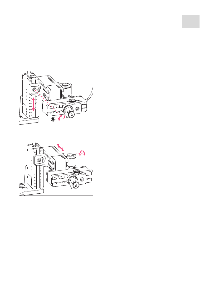
4.8.1 Aligning the height
1. Undo the screw on the YZ-connector.
2. Align the Y-module on the scale of the
Z-module and tighten the screw.
4.8.2 Aligning the depth
1. Undo the screw on the swivel joint.
2. Align the X-module on the scale of the
Y-module and tighten the screw.
®
4
31
Page 32

Installation
InjectMan
32
®
4
English (EN)
4.8.3 Aligning the width
4.8.4 Aligning the angle head
1. Undo the screw on the Z-module holder.
2. Align the Z-module on the scale of the
microscope adapter and tighten the
screw.
1. Undo the screw on the angle head.
2. Align the angle head on the scale of the
X-module.
4.9 Entering mounting parameters
To facilitate remounting the mounting parameters can be recorded.
1. Enter the mounting parameters in the tables.
4.9.1 Microscope and adapter
Name Type
Microscope
Adapter
Attachment side of the
motor module
Page 33

4.9.2 Motor module
1
Position Description Position [mm]
1 Z-module holder on the adapter
2 Z-module on the Z-module holder
3 YZ-connector on the Z-module
4 YZ-connector on the Y-module
5 Swivel joint on the Y-module
6 Swivel joint on the X-module
7 Angle head on the X-module
3 4
2
5
Installation
InjectMan
English (EN)
6
7
®
4
33
4.9.3 Angle head
Name Position [mm] Degrees
Capillary holder
Injection angle
Page 34

Installation
InjectMan
34
®
4
English (EN)
4.10 Converting the swivel joint for left side mounting
Prerequisites
• 2 mm Allen key
• Right side mounting marks (||) are aligned above each other
1. Rotate the lower joint until both Allen
screws are accessible.
2. Unscrew the Allen screws.
Page 35

InjectMan
English (EN)
3. Remove the stop plate.
4. Rotate the lower joint back.
5. Rotate the upper joint by 180°.
The sliders must be at a 90° angle to
each other.
Installation
®
4
35
Page 36

Installation
InjectMan
36
English (EN)
®
4
6. Align the left side mounting marks (I).
7. Fit the stop plate in such a way that the
pins sit in the holes of the turntable.
8. Rotate the swivel joint by 180°.
9. Screw down the stop plate.
• Left side mounting marks (|) are aligned
above each other.
Page 37

10.Check the position of the joints.
• The sliders must be at a 90° angle to
each other.
90°
4.11 Converting the angle head for left side mounting
Prerequisites
• 1.3 mm Allen key
1. Undo the set screw and pull the knurled
screw off the spindle.
Installation
InjectMan
English (EN)
®
4
37
Page 38

Installation
InjectMan
38
English (EN)
®
4
2. Rotate the angle head by 180°.
3. Push the knurled screw onto the spindle
end and fasten it with the set screw.
4. Turn the knurled screw until the desired
+
angle is set.
4.12 Connect the motor module to the control board
WARNING! Risk from incorrect supply voltage
Only connect the device to power supplies which correspond with the
electrical requirements on the name plate.
Only use sockets with a protective earth (PE) conductor and suitable power
cable.
NOTICE! Damage to the control board as a result of incorrect handling.
Grasp the control board on the housing.
Do not lift the control board using the joystick.
Never place the control board on the joystick.
Page 39

Installation
InjectMan
English (EN)
NOTICE! Material damage from incorrect connections.
Only electrical connections may be made to devices described in the
operating manual.
Other connections are permitted only following consultation and agreement
with Eppendorf AG.
Only connect devices that meet the safety requirements defined in
IEC 60950-1.
NOTICE! Short circuit caused by incorrect installation.
Failure to observe the order of steps may result in a short circuit.
Prerequisites
• InjectMan 4 is switched off.
• The power cable is disconnected.
1. Connect the module (X,Y,Z) plug with the ports on the control board.
2. Tighten the fixing screws on the plug manually.
3. Connect the power cable.
4. Switch on the mains switch.
5. Set the installation parameters. You can use the software wizard First set-up or the
Installation menu to set the Side and Angle parameters.
®
4
39
4.13 Setting installation parameters
Installation parameters must be set:
• for the first set-up
•after a reset
The following settings are defined:
• Installation side of the motor module
• Operating angle for the capillary
• Center motors
• Adjust motors
•Set date
Page 40

Installation
InjectMan
40
®
4
English (EN)
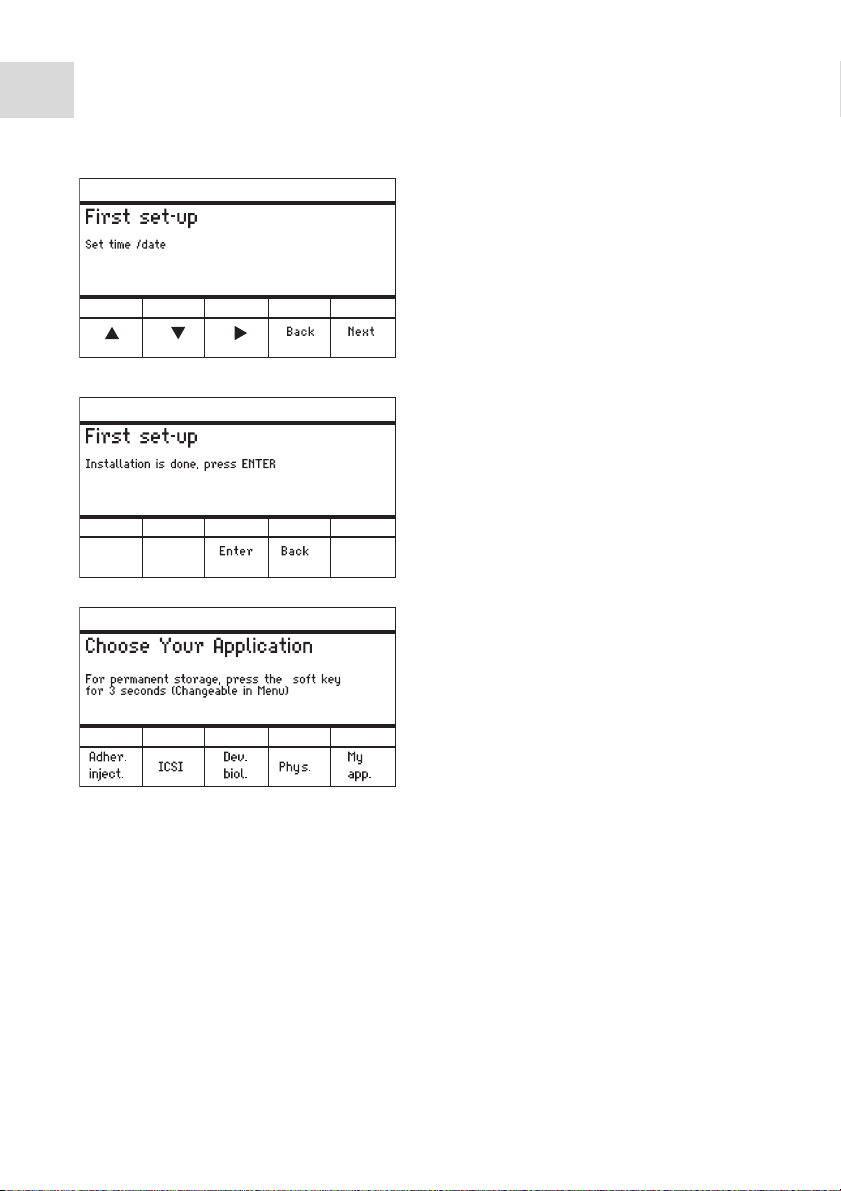
4.13.1 First set-up wizard
Prerequisites
• The micromanipulator is switched on.
1. Select the First set-up application.
2. Select the installation side.
3. Select Next.
4. Set the operating angle.
5. Select Next.
Page 41

Installation
InjectMan
®
English (EN)
6. Select the Execute function to move all
motors to the middle position.
7. Select Next.
8. Insert the capillary holder into the angle
head.
9. Select Next.
10.Manually align the modules.
11.Select Next.
4
41
12.Remove the capillary holder.
13.Insert the capillary into the capillary
holder.
14.Insert the capillary holder with the
capillary into the angle head.
15.Finely adjust the position of the capillary
holder and the modules.
16.Select Next.
Page 42
Installation
InjectMan
42
English (EN)
®
4
17.Set the time and the date.
18.Select Next.
19.Select Enter.
• The installation is complete and the modules are adjusted.
• The application screen displays My application
Page 43

Installation
InjectMan
®
English (EN)
4.14 Connecting an external device
The following devices can be connected to the control board:
• Eppendorf FemtoJet
• Eppendorf PiezoXpert
•Computer
4.14.1 Connecting the FemtoJet
Prerequisites
• Devices are switched off.
The operation is described in the manual for the FemtoJet.
1. Connect the FemtoJet to the port for external devices.
2. Switch on the FemtoJet.
The initialization phase starts.
3. Switch on the control board.
• After completion of the initialization phase, the status message Injector ready appears
on the application screen.
4.14.2 Connecting the PiezoXpert
Prerequisites
• Devices are switched off.
4
43
The operation is described in the manual for the PiezoXpert.
1. Connect the PiezoXpert to the port for external devices.
2. Switch on the PiezoXpert.
The initialization phase starts.
3. Switch on the control board.
• After completion of the initialization phase, the status message PiezoXpert ready
appears on the application screen.
Page 44

Installation
InjectMan
44
®
4
English (EN)
4.14.3 Connecting the Computer
Prerequisites
• A data cable is available.
• Devices are switched off.
Control with a computer is described in the Cell Technology · PC Control
manual.
1. Connect the data cable to the port for external devices.
2. Connect the computer to the data cable.
3. Switch on the control board.
4.14.4 Connecting two devices
Prerequisites
• Y-connector is available.
• Devices are switched off.
Two devices can be connected with a Y-connector.
The following combinations are possible:
• Computer and FemtoJet
• FemtoJet and PiezoXpert
1. Connect the Y-connector to the port for external devices.
2. Connect the device combination.
3. Connect the devices.
• After initialization, status messages appear on the application screen.
Page 45

Software
InjectMan
English (EN)
®
5 Software
5.1 Display
The display shows current settings, for example, the selected working range, the position
of the motors and defined limits.
5.1.1 Application display
Abb. 5-1:Display layout - ICSI application as an example
4
45
1
2
3
4
5
Fig. 5-1: Display layout - ICSI application as an example
1 Status line with working range
2 Active application with speed bars
3 Connected device
4 Status fields of the softkeys
5 Softkeys
6 Function of the joystick key
7 Display of coordinates
8 Display of the defined limits
6
7
8
Page 46
46
Software
InjectMan
®
4
English (EN)
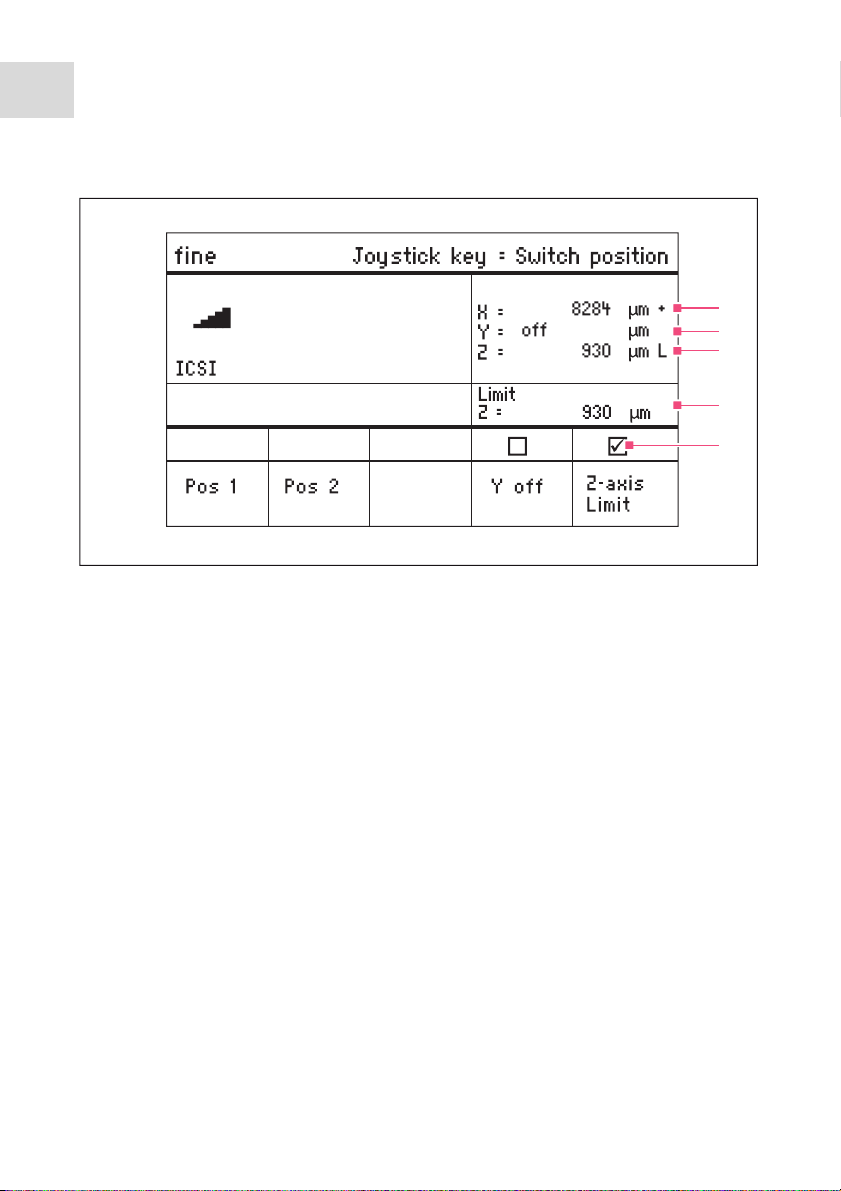
5.1.2 Display of coordinates
Abb. 5-2:Display of coordinates
Fig. 5-2: Display of coordinates
1
2
3
4
5
1 Motor limit stop
+ = positive, - = negative
2 Axis is deactivated
3 Lower limit (Z-axis Limit) reached
4 Display of the lower limit
5 Lower limit activated
Page 47
5.1.3 Menu display
Abb. 5-3:Menu and parameter display
1
Software
InjectMan
English (EN)
®
4
47
2
3
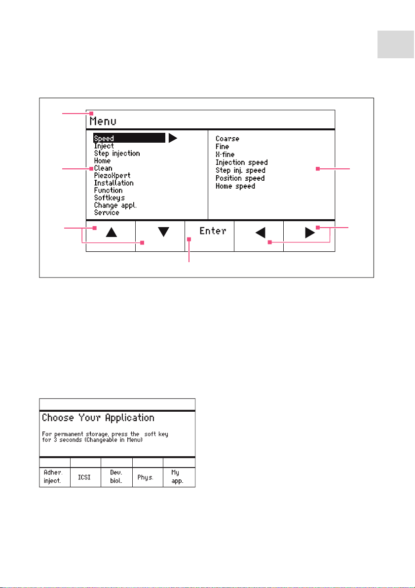
Fig. 5-3: Menu and parameter display
1 Navigation path
2 Menu
3 Arrow up/down softkey
For navigation and changing
parameters.
5.2 Applications
Abb. 5-4:Application screen
6
5
4
4 Enter softkey
For confirming input, executing the
function, saving parameters
5 Arrow left/right softkey
Navigation
6 Parameter
Fig. 5-4: Application screen
Page 48

48
Software
InjectMan
®
4
English (EN)
Application selection
• Select the application
• Store the main application
5.2.1 Application parameter
Predefined functions of the different applications.
• Pos 1 – Save the X, Y and Z values of the capillary position. Switch the position using
the joystick key.
• Pos 2 – Save the X, Y and Z values of the capillary position. Switch the position using
the joystick key.
• Activate or deactivate the Step inject function.
• Y off – Switch off the movement of the capillary in the Y-axis. Prevents moving
sideways during injection.
• Z-axis Limit – Save the downward limit for the vertical capillary movement.
• Axial – Switch on the capillary movement along the assembly bracket. Suitable for
straight capillaries.
• Reduce or increase the Limit value for the limit.
•Execute the Clean function.
5.2.2 Application – Adherent cell injection
This application is suitable for injection into adherent cells.
Abb. 5-5:Application 1 Adherent cell injection
Fig. 5-5: Application 1 Adherent cell injection
Parameter selection
• Joystick key – Inject
• Freely program the softkey
• Reduce the value for Z-axis Limit
• Set the lower limit (Z-axis Limit)
• Increase the value for Z-axis Limit
• Execute the function
Page 49

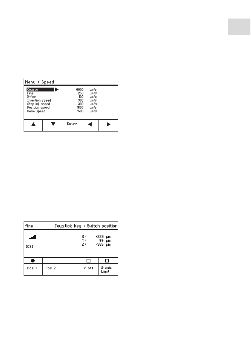
5.2.3 Application – ICSI
This application is suitable for intracytoplasmic sperm injection.
Abb. 5-6:Application 2 ICSI
Fig. 5-6: Application 2 ICSI
Parameter selection
• Joystick key – Switch position
• Save positions 1 and 2
• Freely program the softkey
• Deactivate the control of the axis of movement (Y-axis)
• Set the lower limit (Z-axis Limit)
5.2.4 Application – Developmental biology
This application is suitable for developmental biology.
Abb. 5-7:Application 3 Developmental biology
Software
InjectMan
English (EN)
®
4
49
Fig. 5-7: Application 3 Developmental biology
Parameter selection
• Joystick key – Inject
• Save position 1
• Activate the Step inject function
• Switch on the axial movement of the Z-axis
• Freely program the softkey
• Set the lower limit (Z-axis Limit)
Page 50

50
Software
InjectMan
®
4
English (EN)
5.2.5 Application – Physiology
This application is suitable for physiology.
Abb. 5-8:Application 4 Physiology
Fig. 5-8: Application 4 Physiology
Parameter selection
• Joystick key – Joystick off
• Save position 1
• Freely program the softkey
• Switch on the axial movement of the Z-axis
• Deactivate the control of the axes of movement (X and Y-axis)
• Set the lower limit (Z-axis Limit)
5.2.6 Application – My application
No softkeys are preprogrammed for this application. This application can be individually
programmed.
Abb. 5-9:Application 5 My application
Fig. 5-9: Application 5 My application
Parameter selection
• Freely program the joystick key
• Freely program all softkeys
Page 51

Software
InjectMan
English (EN)
5.3 Main menu
Abb. 5-10:Main menu
Fig. 5-10: Main menu
Menu Parameter
Speed Set the speed parameters
Inject Set the injection parameters
Step injection Set the injection parameters
Home Set the parameters for the Home movement
Clean Set the parameters for the Clean movement
PiezoXpert Set the parameters for an optional device
Installation Set the device parameters
Function Execute the device function
Softkeys Program softkeys
Change appl. Change the selected application or activate the application screen
Service Execute the service function on a user basis
®
4
51
Page 52

52
Software
InjectMan
®
4
English (EN)
5.4 Navigating the menu
Abb. 5-11:Software navigation
Fig. 5-11: Software navigation
Navigate the menu using the arrow keys. Pressing Enter will confirm the selection. You
can switch between menus and submenus with the arrow keys to the left and to the right.
5.4.1 Entering or changing parameters
Parameters can be changed in the menu using the arrow keys, the selection dial or the
rotating wheel on the joystick.
Abb. 5-12:Changing the parameters
Change values with the upwards or
downwards arrow keys.
Change values using the selection dial.
Change values using the upper part of
the joystick.
Save with Enter.
Fig. 5-12: Changing the parameters
Page 53

6Operation
WARNING! Electric shock due to damage to device or mains cable.
Only switch on the device if the device and mains cable are undamaged.
Only use devices that have been properly installed or repaired.
In case of danger, disconnect the device from the mains supply by pulling the
power plug from the device or the mains socket or, by using the isolating
device intended for this purpose (e.g., emergency stop switch in the
laboratory).
Do not move the joystick immediately after power-on. Wait until the initialization
is completed. The completion of initialization is indicated by the display
switching to the operating state.
6.1 Switching the device on or off
6.1.1 Switching on the device
1. Switch on the device at the mains power switch.
• The motor module and the control board are switched on.
• The device runs through an initialization phase.
• The application screen will appear.
6.1.2 Switching the device off
1. Switch off the device at the mains power switch.
The motor module and the control board are deenergized.
Operation
InjectMan
English (EN)
®
4
53
6.2 Activating or deactivating the control board
6.2.1 Activating the control board
Prerequisites
• The display shows STANDBY.
1. Press the standby key.
• The keys, joystick, selection dial and softkeys are activated.
• The display shows the application screen.
6.2.2 Deactivating the control board
The step m otors slowly move to the ne xt parking position. This prevents the motors falling
back to the parking position and the capillary jumping.
1. Press the standby key.
• The keys, joystick and selection dial are deactivated
• The display shows STANDBY.
Page 54

Operation
InjectMan
54
English (EN)
• Current movements are stopped.
• The motor module remains switched on so that the step motors keep their current
position.
®
4
6.3 Defining the start screen
An application can be selected as the default application. The micromanipulator then
starts with the defined application. The application screen with all the applications can be
redefined in the Start display menu.
6.3.1 Defining the application
1. Press and hold the softkey of the desired application for 3 seconds.
• The micromanipulator starts with the defined application.
6.3.2 Defining the selected application
1. In the Change appl. menu, select the Start display submenu.
2. Confirm with Execute.
3. Close the menu.
• The micromanipulator starts with the selected application.
6.4 Replacing the capillary
Prerequisites
• The capillary is depressurized.
WARNING! Risk of injury due to flying capillaries and glass splinters.
If exposed to high pressures, capillaries may detach themselves from the grip
heads and become projectiles.
Capillaries can crack as a result of incorrect handling.
Wear protective goggles.
Never aim capillaries at people.
Use capillaries with an outer diameter that matches the grip head
specifications.
Always mount / dismount capillaries when they are depressurized.
Mount the capillary correctly in the grip head.
Do not touch the capillary with the Petri dish or other objects.
CAUTION! Risk of injury from capillaries
Capillaries can easily penetrate your skin.
After changing a capillary, swivel it immediately back to the working range.
Page 55

Operation
InjectMan
®
English (EN)
CAUTION! Risk of crushing between the modules
The modules automatically move in all spatial axes.
Do not reach into the movement range of the modules.
1. Move the capillary out of the working range using the home key.
2. Swing the X-module forwards.
3. Undo the grip head on the capillary holder.
4. Carefully pull the capillary out of the grip head.
5. Push the new capillary into the grip head until it reaches the stop and tighten the grip
head.
6. Swing the X-module back.
4
55
6.4.1 Manually positioning the capillary
Suitable when using capillaries of different lengths (e.g., self-pulled capillary).
1. Press Back manual.
2. Manually position the capillary in the working range.
6.4.2 Automatically positioning the capillary
Suitable when using industrial capillaries (e.g., Femtotips).
1. Press home.
• The capillary automatically moves back into the working range.
Page 56

56
Operation
InjectMan
®
4
English (EN)
6.5 Changing the sample
CAUTION! Risk of crushing between the modules
The modules automatically move in all spatial axes.
Do not reach into the movement range of the modules.
1. Press the home key to move the capillary
2. Swing the X-module backwards.
3. Change the sample.
4. Swing the X-module back.
5. Press the home key to move the capillary
6.6 Changing the speed range
6.6.1 Changing parameters using the selection dial
out of the working range.
back into the working range.
coarse
1. Press the key for the desired speed range
on the control panel.
2. Turn the selection dial to change the
fine
fine
menu
speed.
Page 57
Operation
InjectMan
®
English (EN)
6.6.2 Changing parameters in the menu
Prerequisites
• An application has been selected.
1. Press the menu key.
2. Select theSpeed menu.
3. Select the desired parameter.
4. Change the value.
6.7 Capillary positions
To secure the capillary when moving a slide and to move it back to the same work position
you can store the positions. Depending on the application, a maximum of five positions
can be stored.
As soon as the capillary leaves a stored position, the filled circle is displayed as an empty
circle, to show that this position is now stored. If no positions are stored, the status field
will be empty.
4
57
6.7.1 Saving a position
Prerequisites
• An application has been selected.
1. Move the capillary to the desired
position.
2. Hold the Pos 1 softkey for approx. one
second to store the working position of
the capillary.
• An acoustic signal will sound.
• Pos 1 is marked.
• The stored position is displayed in the
status field.
Page 58

Operation
InjectMan
58
English (EN)
®
4
3. Move the capillary to the desired
position (e.g., parking position).
4. Press and hold the Pos 2 softkey for
approx. one second to store the parking
position of the capillary.
• An acoustic signal will sound.
• Pos 2 is marked.
• The stored position is displayed in the
status field.
6.7.2 Moving to the position using the softkey
Prerequisites
• At least one position is stored.
1. Press a softkey with a stored position.
• You will move to the selected position.
• The joystick is deactivated until the position has been reached.
• The LEDs of the softkeys flash.
• In the softkey status field a filled circle is displayed.
If a stored position is lower than the lower limit (Z-axis Limit), the position on the
Z-axis will only be approached up to the defined limit.
6.7.3 Moving to the position using the joystick key
Prerequisites
• At least one position is stored.
•The Joystick key parameter must be set to the Switch position value.
Press the joystick key.
You will move to the first position
Press the joystick key.
• You will move to the next position.
6.7.4 Deleting a stored position
Prerequisites
• A position is stored.
1. When the position has been reached, hold the softkey.
• An acoustic signal will sound.
• The position has been deleted.
• The status field is empty
Page 59
Operation
InjectMan
®
English (EN)
6.7.5 Overwriting a stored position
Prerequisites
• A position is stored.
1. Press the softkey for a different position.
• You will move to the position.
2. When the position has been reached, press and hold the softkey for the position to be
overwritten.
• The old position is overwritten with the current coordinates.
3. Press the softkey.
• An acoustic signal will sound.
• In the softkey status field a filled circle is displayed.
• The stored position is displayed in the coordinate field.
6.8 Vertical limits
For the Z-axis, a lower and upper limit can be defined. This prevents the capillary coming
into contact with the bottom of the Petri dish or moving against the condenser of the
microscope adapter.
•Lower limit – Z-axis Limit
• Upper limit – Upper limit
4
59
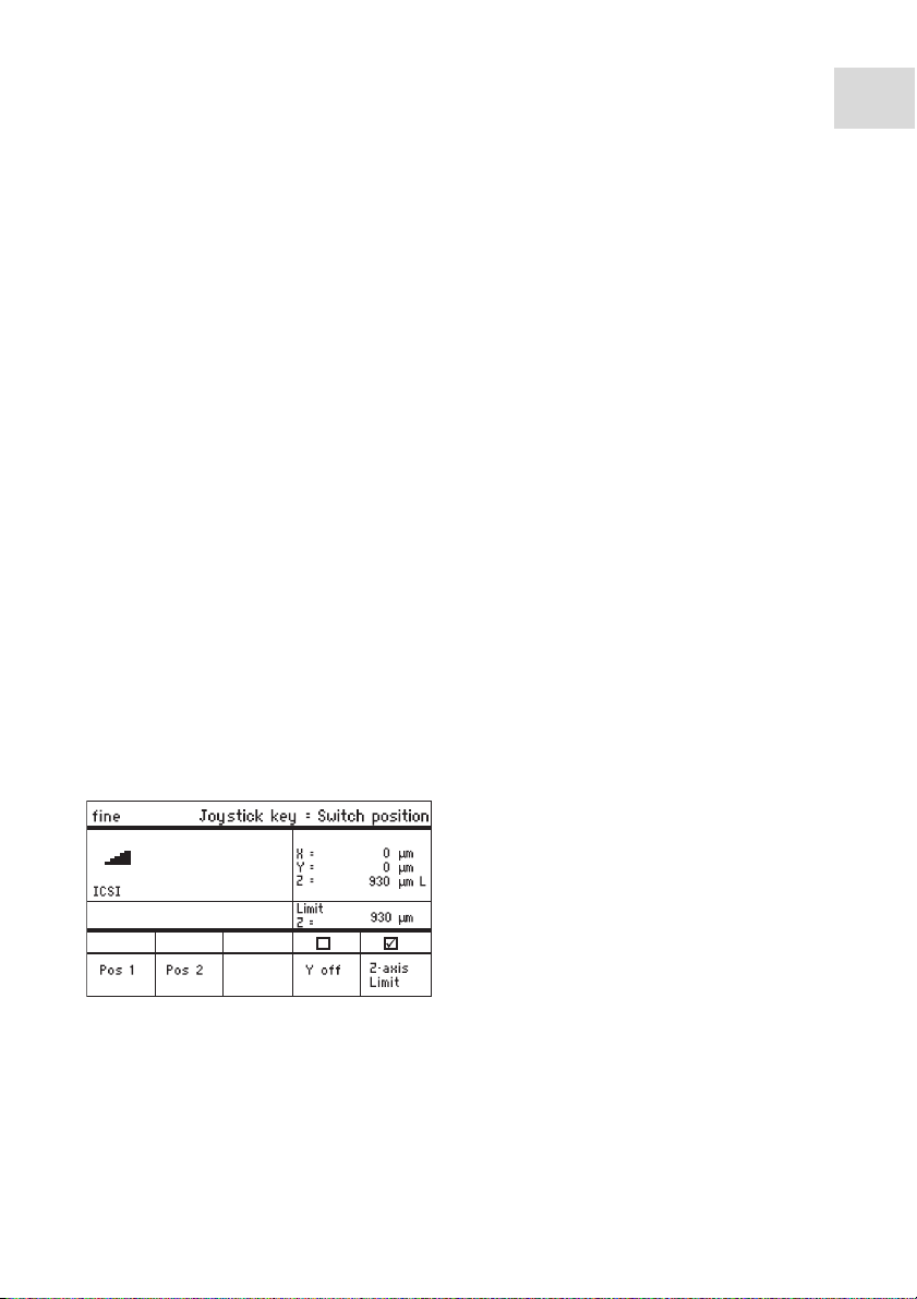
6.8.1 Defining the lower limit
Prerequisites
• An application has been selected.
1. Position the capillary a little way above the slide.
2. Press Z-axis Limit.
• The Z-coordinate is marked with L.
• The value for the limit (Limit Z) is displayed.
• Z-axis Limit is selected.
• The capillary cannot be moved any lower.
Page 60

60
Upper Limit
Menu / Installation / Upper Limit
Back
Set
Clear
X
Y
Z
Lim
=
=
=
0
0
2671
2671
µm
µm
µm U
µm
Operation
InjectMan
®
4
English (EN)
6.8.2 Deleting the lower limit
1. Press Z-axis Limit.
• The limit is deleted.
6.8.3 Defining the upper limit
1. In the Installation menu, select the Upper limit submenu.
The Upper Limit window appears.
2. Move the capillary to the top position.
3. Save the position with Set.
• The Z-coordinate is marked with U.
• The value for the limit (Lim) is displayed.
• The capillary cannot be moved any higher.
6.8.4 Deleting the upper limit
1. In the Installation menu, select the Upper limit submenu.
The Upper Limit window appears.
2. Save the position with Clear.
• The limit is deleted.
Page 61
Operation
InjectMan
®
English (EN)
6.9 Horizontal limit
For the X-axis, a limit can be defined for a horizontal injection. This prevents the capillary
from moving through the sample.
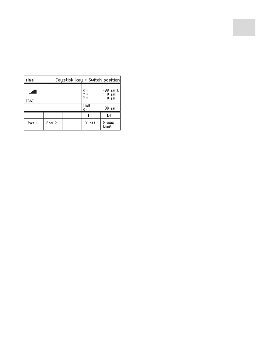
6.9.1 Defining the horizontal limit
1. In the Installation menu, select the Angle submenu.
2. Set the injection angle to 0° and save with Enter.
3. Close the menu.
The application screen now displays X-axis Limit.
4. Move the capillary to the desired final position for the X-axis.
5. Save the lateral limit with X-axis Limit.
• The X-coordinate is marked with L.
• The value for the limit (Limit X) is displayed.
• X-axis Limit is selected.
• The capillary cannot be moved any further to the side.
4
61
6.9.2 Deleting the horizontal limit
1. Press X-axis Limit.
The limit is deactivated.
2. In the Installation menu, select the Angle submenu.
3. Reset the injection angle to the operating angle and save with Enter.
• The lateral limit is deleted.
• The application screen displays Back again.
Page 62

62
Operation
InjectMan
®
4
English (EN)
6.10 Speed function
In the Speed menu you can set the speed of the working range and the speed at which
certain positions are approached or movements executed.
6.10.1 Speed menu and parameters
Abb. 6-1:Menu – Speed
Fig. 6-1: Menu – Speed
Parameter Value Range of values Increment Standard
Coarse Set the speed in μm per
5 – 10000 5 7500
second
Fine Set the speed in μm per
5 – 1000 5 1000
second
X-fine Set the speed in μm per
0 – 100 1 100
second
Injection speed Set the speed in μm per
5 – 10000 5 300
second
Step inj. speed Set the speed in μm per
5 – 10000 5 300
second
Position speed Set the speed in μm per
5 – 10000 5 1500
second
Home speed Set the speed in μm per
5 – 10000 5 7500
second
6.10.2 Setting the parameters for Speed
If a value of 0 is set for the X-fine parameter, then the change between the Fine
and X-fine working ranges is deactivated.
1. Select the desired parameter.
2. Set the value for the parameter.
3. Close the menu.
Page 63

Operation
InjectMan
®
English (EN)
6.11 Inject function
This function performs an automatic injection movement. You can set the injection speed,
the injection time, the injection movement and fix the distance between the capillary and
the lower limit.
6.11.1 Inject menu and parameters
Abb. 6-2:Menu – Inject
Fig. 6-2: Menu – Inject
Parameter Value Range of values Increment Standard
Injection speed Set the injection speed in μm
5 – 10000 5 300
per second
Synchr. inject. Set the synchronized time of
injection
MOVE
IMMEDIATE
– LIMIT
LIMIT
PRESSURE
Search+limit Change the lower limit and
OFF/ON – OFF
the position of the capillary.
The distance between the
capillary and the limit
remains constant
Injection axial Switch the axial movement of
OFF/ON – On
the function on or off
4
63
Parameter Range of values Function
Synchr. inject. MOVE Injection movement without injection pressure (when
using non-connected injectors)
IMMEDIATE Injection pressure starts with the injection movement
LIMIT Injection pressure at the end of the injection distance
(Z-axis Limit)
PRESSURE Injection pressure without injection movement
Page 64

Operation
InjectMan
64
English (EN)
®
4
6.11.2 Executing the Inject function
Prerequisites
• A FemtoJet is connected.
• A lower limit (Z-axis Limit) has been defined.
1
5
6
7
8
3
1 Position the capillary
2 Trigger an automatic injection
3 Injection
4 Automatic movement to the starting
position
If the Search+limit parameter is activated you can inject cells with different
heights using the same injection parameters.
1. Press the joystick key.
• The capillary is moved to the side and to the lower limit at the injection angle.
• The injection is carried out automatically.
• The capillary is moved back to the starting position.
5 Capillary
6 Search level
7 Z-axis Limit
8 Cell
2
4
Page 65

Operation
InjectMan
English (EN)
6.12 Step injection function
With this function you can execute a straight injection over a defined distance. Step
injection can only be executed when a FemtoJet is connected.
6.12.1 Step injection menu and parameters
Abb. 6-3:Menu – Step injection
Fig. 6-3: Menu – Step injection
Parameter Value Range of values Increment Standard
Step injection Switch the function on or off OFF/ON – OFF
Step inj. speed Set the injection speed in μm
5 – 10000 5 300
per second
Step inj. dist. Set the injection path in μm 1 – 2000 1 20
Step inj. axial Switch the axial movement of
OFF/ON – On
the capillary on or off
Step inj. back Switch the backward
OFF/ON – On
movement of the capillary on
or off
Synchr. inject. Set the time of injection MOVE
– LIMIT
IMMEDIATE
LIMIT
PRESSURE
®
4
65
Parameter Range of values Function
Synchr. inject. MOVE Injection movement without injection pressure
IMMEDIATE Injection pressure starts with the injection movement
LIMIT Injection pressure at the end of the injection distance
(Step inj. dist.)
PRESSURE Injection pressure without injection movement
Page 66

66
Operation
InjectMan
®
4
English (EN)
6.12.2 Executing the Step injection function
Prerequisites
• A FemtoJet is connected.
• Step injection is assigned to a free softkey.
1. Activate Step injection.
2. Set all parameters.
3. Set the injection time on the FemtoJet.
4. Close the menu.
• The application screen displays Step injection.
5. Trigger the injection with the joystick key.
• The function is executed.
6.13 Home function
The Home function quickly moves the capillary out of the work area and is suitable for a
quick change of capillary.
6.13.1 Home menu and parameters
Abb. 6-4:Menu – Home
Fig. 6-4: Menu – Home
Parameter Value Range of values Increment Standard
Home speed Set the speed of the Home
5 – 10000 5 7500
function
Home offset Set vertical offset in μm 5 – 20000 5 0
6.13.2 Setting the parameter for Home
1. Set the speed.
2. Set the offset.
3. Close the menu.
Page 67

6.13.3 Move the capillary out with the home key
Prerequisites
• The parameters in the Home menu have been defined.
CAUTION! Risk of crushing between the modules
The modules automatically move in all spatial axes.
Do not reach into the movement range of the modules.
1. Press the home key.
The home key flashes.
• The capillary is moved out of the work
area.
•The home key lights up.
6.13.4 Move the capillary back with the home key
CAUTION! Risk of crushing between the modules
The modules automatically move in all spatial axes.
Do not reach into the movement range of the modules.
Operation
InjectMan
English (EN)
®
4
67
1. Press the home key.
• The capillary is moved back into the work area.
•The home function is terminated.
6.13.5 Setting the offset.
For capillaries of different lengths, an offset can be set. This defines a limit for the home
function.
Page 68

68
Operation
InjectMan
®
4
English (EN)
1. Change the offset using the arrow keys.
• The value for the offset is displayed in the status field.
6.13.6 Terminate the home function.
1. Press Back manual.
2. Move the capillary manually using the
The home function is terminated.
joystick.
6.14 Clean function
With this function you can move the capillary over a defined distance out of the medium.
In the process, outside contamination is removed from the capillary at the medium
boundary.
6.14.1 Clean menu and parameters
Abb. 6-5:Menu – Clean
Fig. 6-5: Menu – Clean
Page 69

Operation
InjectMan
English (EN)
Parameter Value Range of values Increment Standard
Home speed Set the speed of the clean
5 – 10000 5 7500
function
Clean distance Set distance in μm 0 – 20000 5 10000
6.14.2 Setting the parameter for Clean
Set the Clean distance above the medium boundary
1. Set Home speed.
2. Set Clean distance.
3. Close the menu.
6.14.3 Execute the Clean function
Prerequisites
• Parameters are set for Clean.
• Clean is assigned to a softkey.
1. Press Clean.
The screen for Clean appears.
2. Execute the function with Clean.
®
4
69
• The capillary is moved out of the medium with the set parameters.
6.14.4 Terminate the Clean function.
1. Press Back manual.
• The function is terminated.
• The application screen appears.
Page 70

70
Operation
InjectMan
®
4
English (EN)
6.15 PiezoXpert function
6.15.1 PiezoXpert menu and parameters
Abb. 6-6:Menu – PiezoXpert
Fig. 6-6: Menu – PiezoXpert
Parameter Value Range of values Increment Standard
Synchr.
PiezoXp.
Switch synchronization
between InjectMan 4 and
OFF/ON
PiezoXpert on or off
PiezoXp. speed Set the advance rate of the
5 – 10000 5 300
manipulator in μm/s while
the PiezoXpert triggers a
pulse.
PiezoXp. dist. Set the length of the
1 – 2000 1 20
movement step of the
manipulator in μm while the
PiezoXpert triggers a pulse.
PiezoXp. axial Axial movement on or off
ON/OFF – OFF
(corresponds to the set
injection angle)
On = movement in the X and
Y-axis.
Off = movement in the X-axis
Page 71

Operation
InjectMan
English (EN)
6.15.2 Execute the PiezoXpert function
Prerequisites
• A PiezoXpert is connected.
1. Activate Synchr. PiezoXp.
2. Set PiezoXp. speed.
3. Set PiezoXp. dist.
4. Select PiezoXp. axial.
5. Close the menu.
6. Trigger the function with Channel A on the PiezoXpert.
• The function is executed.
6.16 Installation function
This function provides settings for finely adjusting the motor module and the control
board. Parameters in the Installation menu disable identical softkey functions.
6.16.1 Installation menu and parameters
Abb. 6-7:Menu – Installation
®
4
71
Fig. 6-7: Menu – Installation
6.16.2 Installation parameters
Parameter Value Range of values Increment Standard
Side Set the mounting side LEFT/RIGHT – RIGHT
Angle Set the capillary angle in
0° – 90° 1 –
degrees
6.16.3 Control board parameters
Parameter Value Range of values Increment Standard
LCD contrast Set the display contrast 65 % – 75 % 1 70 %
LCD light Set the brightness level of the
0 % – 100 % 1 100 %
display
Page 72

72
Operation
InjectMan
®
4
English (EN)
Parameter Value Range of values Increment Standard
Beeper Set the volume 0 – 100 % 1 50 %
Display
Set the coordinate display OFF/ON – On
coordin.
6.16.4 Module parameters
Parameter Value Range of values Increment Standard
Invert X-axis Reverse the direction of
OFF/ON – OFF
movement of the motor
Invert Y-axis Reverse the direction of
OFF/ON – OFF
movement of the motor
Invert Z-axis Reverse the direction of
OFF/ON – OFF
movement of the motor
X-axis off Switch the motor of the
OFF/ON – OFF
movement axis on or off
Y-axis off Switch the motor of the
OFF/ON – OFF
movement axis on or off
Z-axis off Switch the motor of the
OFF/ON – OFF
movement axis on or off
Upper limit Define the upper limit EXECUTE – –
6.17 Function function
Function allows you to reset the parameters and coordinates and to move the modules to
the middle position.
6.17.1 Function menu and parameters
Abb. 6-8:Menu – Function
Fig. 6-8: Menu – Function
Parameter Value Range of values
Zero coordin. Reset all coordinates to zero Execute
Page 73

Operation
InjectMan
English (EN)
Parameter Value Range of values
Center motors Move step motors of the motor module to the middle
position
User default Reset the settings to the delivery status Execute
Execute
6.17.2 Executing Zero coordin.
1. Select the parameters and confirm with Enter.
2. Confirm Execute with Enter.
• All coordinates are reset to zero.
• Saved positions are deleted.
• Set limits are deleted.
6.17.3 Executing Center motors
Prerequisites
• No capillary holder is clamped.
CAUTION! Risk of crushing between the modules
The modules automatically move in all spatial axes.
Do not reach into the movement range of the modules.
®
4
73
1. Select the parameters and confirm with Enter.
2. Confirm Execute with Enter.
• X-motor and Y-motor are moved to the middle position.
• Z-motor is moved to a 20/80 position.
• All coordinates are reset to zero.
• Saved positions are deleted.
• Set limits are deleted.
6.17.4 Executing User default
1. Select the parameters and confirm with Enter.
2. Confirm Execute with Enter.
• All parameters are reset to the factory settings.
• The application screen appears.
Page 74

74
Operation
InjectMan
®
4
English (EN)
6.18 Softkeys function
With this function you can assign programs to free softkeys. Assigned softkeys are
indicated with a lock symbol.
6.18.1 Softkeys menu and parameters
Abb. 6-9:Menu – Softkeys
Fig. 6-9: Menu – Softkeys
Parameter Value Range of values
Softkey 1 Set the function
Softkey 2 Set the function
Softkey 3 Set the function
Softkey 4 Set the function
Softkey 5 Set the function
Joystick key Set the function for the joystick key No function
Switch position
Switch fine
Joystick off
Inject
Parameter Function
No function Softkey has no function
Pos 1 Save, overwrite or delete a position
Pos 2 Save, overwrite or delete a position
Pos 3 Save, overwrite or delete a position
Pos 4 Save, overwrite or delete a position
Pos 5 Save, overwrite or delete a position
Y-axis off Switch the control of the movement axis on or off
Axial Change vertical movement to axial movement
Limit Activate or deactivate the vertical or horizontal (X-axis) limit
Page 75

Operation
InjectMan
English (EN)
Parameter Function
Step injection Activate the Step injection function
Limit up Change the value for Z-axis Limit upwards
Limit down Change the value for Z-axis Limit downwards
Clean Axial movement out of the working range
Z-axis only Only control of movements in the Z-axis. The control of movements in
the X and Y-axis is disabled
LCD light Set the brightness level of the display
Beeper Set the volume
Joystick off Deactivates all joystick movements
X-axis off Switch the control of the movement axis on or off
Z-axis off Switch the control of the movement axis on or off
X-axis only Only control of movements in the X-axis. The control of movements in
the Y and Z-axis is disabled
Y-axis only Only control of movements in the Y-axis. The control of movements in
the X and Z-axis is disabled
Parameter Range of values Function
Joystick key No function Deactivate the function of the joystick key
Switch position Click once to go to the next saved position
Switch fine Click once to go to the fine or x-fine working range
Joystick off Click once to switch the joystick on or off
Inject Click once to activate the function
®
4
75
6.18.2 Executing Softkeys
1. Select the free softkey and confirm with Enter.
2. Select the desired parameter and confirm with Enter.
3. Close the menu.
• The selected parameter is assigned to the free softkey.
• The parameter appears on the application screen.
Page 76
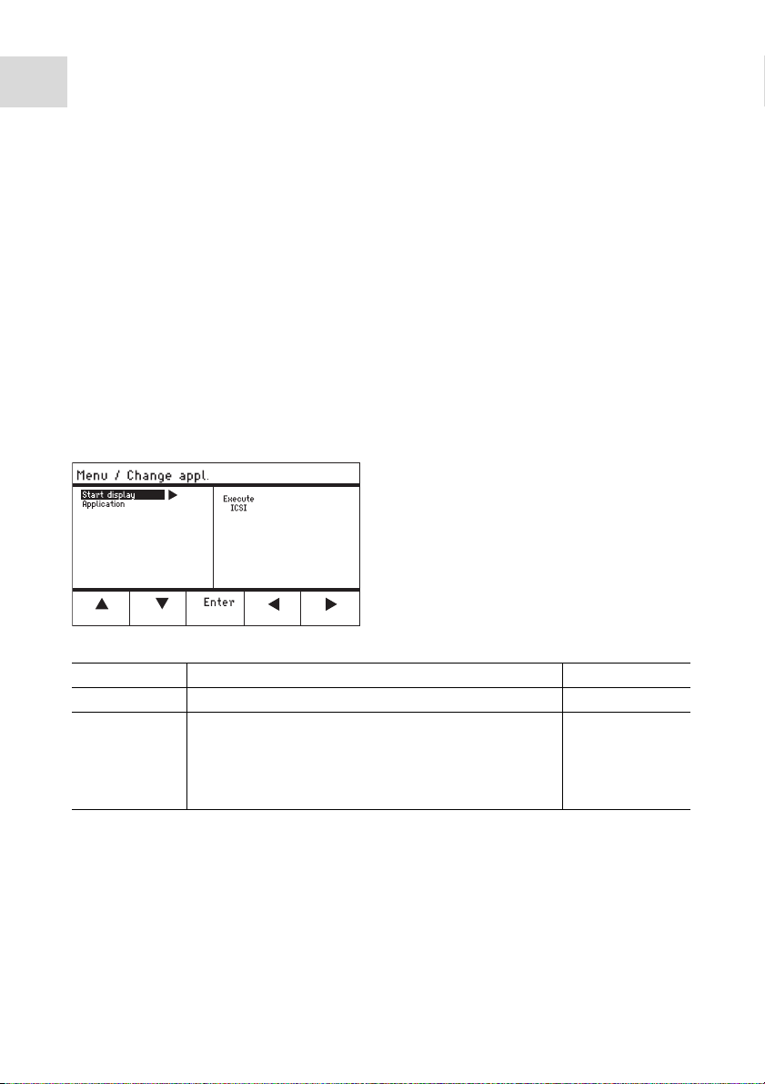
76
Operation
InjectMan
®
4
English (EN)
6.18.3 Executing Joystick key
Prerequisites
The My application application has been selected.
1. Select Joystick key and confirm with Enter.
2. Select the desired function and confirm with Enter.
3. Close the menu.
• The function is assigned to the joystick key.
• The selected function appears on the application screen.
6.19 Change appl. function
With this function you can define each application as the start screen or reactivate the
default screen.
6.19.1 Change appl. menu and parameters
Abb. 6-10:Menu – Change appl.
Fig. 6-10: Menu – Change appl.
Parameter Value Range of values
Start display Reactivate start screen to select an application Execute
Application Define the selected application as the start screen Adherent cell inj
ICSI
Dev. biology
Physiology
My application
6.19.2 Defining the selected application as the start screen
1. Select Start display.
2. Confirm with Execute.
3. Close the menu.
• The micromanipulator starts with the selected application.
Page 77

Operation
InjectMan
English (EN)
6.19.3 Defining the application as the start screen
1. Select the application.
2. Confirm with Enter.
3. Close the menu.
• The micromanipulator always starts with the defined application.
6.20 Service function
6.20.1 Service menu and parameters
Abb. 6-11:Service
Fig. 6-11: Service
Parameter Value Range of values
Selftest Move the motor module in all three axes and output
Execute
error message
Device info Display software version Execute
Set clock Set date and time YYYY-MM-DD
00:00
Movements Show movement routes of the modules (X, Y, Z) Execute
Show errors Display last 10 error messages Execute
Demo run Save the position and move to it Execute
®
4
77
Page 78

Operation
InjectMan
78
English (EN)
®
4
6.20.2 Execute the Selftest function
CAUTION! Risk of crushing between the modules
The modules automatically move in all spatial axes.
Do not reach into the movement range of the modules.
1. Select Selftest and confirm with Enter.
2. Confirm Execute with Enter.
The screen for the Selftest function appears.
3. Execute Selftest with Start.
The motors move up to the limit stops.
4. Terminate Selftest with Stop.
6.21 Resetting parameters to the factory settings
6.21.1 Perform reset
Reset all parameters to the factory settings.
1. Keep the home key pressed.
2. Switch on the device at the mains power switch.
The screen for GENERAL RESET appears.
3. Execute the function with Yes.
• All parameters are now reset to the factory settings.
6.21.2 Carrying out a reset in the menu
Prerequisites
• An application has been selected.
1. Press the menu key.
2. Select the Function menu.
3. Press Enter.
4. Select User default and confirm with Execute.
• All parameters are now reset to the factory settings.
6.22 Remote computer control of the InjectMan 4
You can control the InjectMan 4 by means of a terminal program remotely via computer.
Computer control by means of a terminal program is only recommended for certain
applications and is not described in this operating manual. A special operating manual for
this functionality is available at the following Internet address: www.eppendorf.com
Eppendorf does not provide any support for controlling the InjectMan 4 by
means of a terminal program.
.
Page 79

7 Troubleshooting
7.1 General errors
7.1.1 Motor module
Symptom/message Cause Remedy
Motor axes move in the
wrong direction or do
not match joystick
movement.
• Motor module mounted
incorrectly.
• Incorrect installation
parameters entered.
• Direction of movement of
axis inverted.
Compare the installation
parameters with the
structure of the motor
module.
Check the orientation and
structure of the modules.
Check the connections of
the modules at the control
board.
Cancel the inversion of the
axis.
7.1.2 Capillary
Symptom/message Cause Remedy
Capillary moves too
fast or too slow.
Capillary only moves to
the side or vertically.
Capillary does not
move down far
enough.
• Radius of working range
incorrectly set.
• Incorrect acceleration
factor.
• Y-axis is disabled.
•The Z-axis Limit function is
active.
• Capillary is incorrectly
adjusted.
Set the radius using the
selection dial or in the Speed
menu.
In the Installation menu, set
the value for the Dyn-factor
parameter.
The Y off function disabled.
Deactivate the Z-axis Limit
function.
Readjust the capillary.
Troubleshooting
InjectMan
English (EN)
®
4
79
7.1.3 Control board and display
Symptom/message Cause Remedy
Device does not
respond to keystroke
when Home function is
active.
• Function is active.
Press the home key again.
The capillary moves down.
Press the Back manual
softkey.
Move the joystick.
Page 80

Troubleshooting
InjectMan
80
English (EN)
Symptom/message Cause Remedy
The display does not
show anything or the
device cannot be
activated although the
device is connected.
®
4
• The power cable or power
plug is loose.
• The device is switched off.
7.1.4 Joystick
Symptom/message Cause Remedy
Outer movement range
of the joystick does not
work.
• Outer movement range is
deactivated.
7.1.5 Software and parameters
Symptom/message Cause Remedy
Parameters are not
accessible for certain
operations.
–
Check the power cable or
the power plug.
Switch the device on.
In the Installation menu, set
the value for Dyn-mode to
ON.
Enter parameters again.
Carry out a reset and reset
all parameters to the works
settings.
Readjust device.
7.2 Error messages
7.2.1 Warnings
Symptom/message Cause Remedy
WARNING 1 • FemtoJet is not connected.
Disconnect the data cable to
the FemtoJet and connect it
again.
Switch on the FemtoJet.
WARNING 3 • X-module is not connected.
Switch off the device.
Connect the plug of the
X-module to the control
board and tighten.
Switch the device on.
WARNING 4 • Y-module is not connected.
Switch off the device.
Connect the plug of the
Y-module to the control
board and tighten.
Switch the device on.
Page 81

Troubleshooting
InjectMan
English (EN)
Symptom/message Cause Remedy
WARNING 5 • Z-module is not connected. Switch off the device.
Connect the plug of the
Z-module to the control
board and tighten.
Switch the device on.
WARNING 6 • Synchronization error with
FemtoJet during an
injection.
7.2.2 Error
Symptom/message Cause Remedy
ERROR 10 – ERROR 99 • Technical error.
Set another synchronization
for Synchr. inject..
Set the synchronization
IMMEDIATE, LIMIT or
PRESSURE.
Switch the device off and
back on.
Reset the parameters to the
factory settings.
Contact Eppendorf Service.
®
4
81
Page 82

Maintenance
InjectMan
82
English (EN)
®
4
8 Maintenance
8.1 Replacing fuses
DANGER! Electric shock.
Switch off the device and disconnect the power plug before starting
maintenance or cleaning work.
The fuse holder is located between the mains connection socket and the mains power
switch. The fuses may only be replaced with the same type of fuse.
1. Disconnect the mains plug.
2. Pull the fuse holder out completely.
3. Replace the defective fuse.
4. Insert the fuse holder.
8.2 Cleaning
DANGER! Electric shock as a result of penetration of liquid.
Switch off the device and disconnect the power plug before starting cleaning
or disinfection work.
Do not allow any liquids to penetrate the inside of the housing.
Do not spray clean/spray disinfect the housing.
Only plug the device back in if it is completely dry, both inside and outside.
NOTICE! Damage from the use of aggressive chemicals.
Do not use any aggressive chemicals on the device or its accessories, such as
strong and weak bases, strong acids, acetone, formaldehyde, halogenated
hydrocarbons or phenol.
If the device has been contaminated by aggressive chemicals, immediately
clean it by means of a mild cleaning agent.
Prerequisites
• Clean at least every 4 weeks.
1. Wipe the painted parts and the aluminum surfaces with a cloth and mild detergent.
2. Wipe with a dry cloth afterwards.
Page 83

Maintenance
InjectMan
English (EN)
8.3 Service and maintenance
Application-specific service and safety inspections are not required
The Eppendorf AG service team is available to service and certify your device.
Service provisions:
•Service
• Operational qualification (OQ) according to manufacturer's specifications
• Electrical safety testing according to country-specific regulations
•Software update
Information on the services offered can be found on our webpage: www.eppendorf.com/
epservices.
8.4 Disinfection/decontamination
Choose the disinfection method which corresponds to the legal regulations and
guidelines in place for your range of application.
If you have any questions on cleaning, disinfection, decontamination, or the
cleaning agents to be used, please contact Eppendorf AG Application Support.
The relevant contact details are provided on the back of this operating manual.
Prerequisites
• All device parts are cleaned.
• A disinfectant containing alcohol (such as isopropanol or spirit) is available
1. Wipe all parts of the device with a cloth and the disinfectant.
®
4
83
Page 84

Technical data
InjectMan
84
®
4
English (EN)
9 Technical data
Motor module
Travel, maximum 20 mm
Step motors X-module, Y-module, Z-module
Weight 2150 g
Module (X,Y,Z)
Type Step motors
Step size
< 20 nm
(calculated resolution)
Speed, maximum 10000 μm/s
Width 129 mm
Depth 51 mm
Height 36 mm
Weight 570 g
Swivel joint
Direction of rotation -45° – +90°
Capillary change Direction of rotation forwards
Sample change Direction of rotation backwards
Angle head
Operating angle 0° – 90°
Control board
Control Joystick
Working range coarse, fine, x-fine
Width 205 mm
Depth 288 mm
Height 152 mm
Weight 1800 g
Page 85

9.1 Power supply
Control board
Mains connection 120 – 240 V AC, 50 – 60 Hz
Power consumption 30 W
Protection class I
Overvoltage category II (IEC 61010-1)
Micro fuse T 1.6 A, 250 V
9.2 Interfaces
Module (X, Y, Z) SubD25, female
PC/external device Serial interface
SubD9, male
Service connection USB
9.3 Ambient conditions
Environment For indoor use only.
Ambient temperature 15 °C – 35 °C
Max. relative humidity 30 % – 65 %
Degree of pollution 2 (IEC 664)
Technical data
InjectMan
®
English (EN)
4
85
Page 86

Transport, storage and disposal
InjectMan
86
English (EN)
®
4
10 Transport, storage and disposal
10.1 Storage
Air temperature Relative humidity Atmospheric
pressure
In transport
packaging
Without transport
packaging
-25 °C – 55 °C 10 % – 95 % 70 kPa – 106 kPa
-5 °C – 45 °C 10 % – 95 % 70 kPa – 106 kPa
10.2 Decontamination before shipment
If you are shipping the device to the authorized Technical Service for repairs or to your
authorized dealer for disposal please note the following:
WARNING! Risk to health from contaminated device
1. Please observe the information in the decontamination certificate, which is
available as a PDF file on our webpage (www.eppendorf.com/
decontamination).
2. Decontaminate all the parts you would like to dispatch.
3. Include the fully completed decontamination certificate in the package.
10.3 Transport
NOTICE! Damage to the control board as a result of incorrect handling.
Grasp the control board on the housing.
Do not lift the control board using the joystick.
Never place the control board on the joystick.
Air temperature Rel. humidity Atmospheric pressure
General transport -25 °C – 60 °C 10 % – 95 % 30 kPa – 106 kPa
Air freight -40 °C – 55 °C 10 % – 95 % 30 – 106 kPa
Carry out the following steps before transport:
1. Dismantle the module unit before transport.
2. Attach the supplied transport securing devices according to the red supplement sheet.
3. Only use original packaging for transport.
Page 87

Transport, storage and disposal
InjectMan
®
English (EN)
10.4 Disposal
In case the product is to be disposed of, the relevant legal regulations are to be observed.
Information on the disposal of electrical and electronic devices in the European
Community:
Within the European Community, the disposal of electrical devices is regulated by
national regulations based on EU Directive 2002/96/EC pertaining to waste electrical and
electronic equipment (WEEE).
According to these regulations, any devices supplied after August 13, 2005, in the
business-to-business sphere, to which this product is assigned, may no longer be
disposed of in municipal or domestic waste. To document this, they have been marked
with the following identification:
Because disposal regulations may differ from one country to another within the EU,
please contact your supplier if necessary.
In Germany, this is mandatory from March 23, 2006. From this date, the manufacturer has
to offer a suitable method of return for all devices supplied after August 13, 2005. For all
devices supplied before August 13, 2005, the last user is responsible for the correct
disposal.
4
87
Page 88

Ordering Information
InjectMan
88
®
4
English (EN)
11 Ordering Information
11.1 InjectMan 4
Order no.
(International)
Order no. (North
America)
Description
InjectMan 4
5192 000.019 5192000019 Mains/Power plug Europe
5192 000.027 5192000027 Mains/Power plug USA/Japan
5192 000.035 5192000035 Mains/Power plug UK/Hong Kong
5192 000.043 5192000043 Mains/Power plug Australia
5192 000.051 5192000051 Mains/Power plug China
5192 000.060 5192000060 Mains/Power plug Argentina
11.2 Accessories for InjectMan 4
Order no.
(International)
5181 070.015
Order no. (North
America)
Description
Data cable
Connect FemtoJet/FemtoJet express to
920005845
micromanipulator
5181 150.051 920005799 Foot control
Data cable 5181
5181 150.094 920005837 Connect PC or PiezoXpert to micromanipulator
Antivibration Pad
5181 301.009 920007945 XS
5181 303.001 920007953 S
5181 305.004 920007961 M
5181 307.007 920007970 L
5181 309.000 920007988 XL
Spare parts kit
5192 071.005 5192071005 1 slider (complete), 2 machine screws M2.5×6
(swivel joint), 2 set screws (angle head), 2
compression springs (knurled screw angle head)
Positioning aid
2 pieces
5192 072.001 5192072001 for universal capillary holder
Headstage holder
5192 073.008 5192073008 for preamplifier
Page 89

11.3 Tools for InjectMan 4
Ordering Information
InjectMan
®
English (EN)
4
89
Order no.
(International)
Order no. (North
America)
Description
Allen torque screwdriver
5192 074.004 5192074004
3 mm
Allen screwdriver
5192 075.000 5192075000
1.3 mm
Allen key
7 pieces
5192 076.007 5192076007 1.5 mm, 2 mm, 2.5 mm, 3 mm, 4 mm, 5 mm, 6mm
5192 077.003 5192077003 Toolb ag
11.4 Microscope adapter
Order no.
(International)
Order no. (North
America)
Description
Adapter for microscope
Leica 1
5192 301.000 5192301000 DMI3000 B, 3000 M, 4000 B, 5000 B, 5000 M,
6000 B, DM IRB E, HC, DM IRE 2
Adapter for microscope
Leica 2
5192 302.007 5192302007 DM IL LED, HC
Adapter for microscope
Olympus 1
5192 306.002 5192306002 IX50, IX51, IX70, IX80, IX81
Adapter for microscope
Olympus 2
5192 307.009 5192307009 IX53, IX73
Adapter for microscope
Nikon 1
5192 316.008 5192316008 Eclipse® Diaphot 200, 300, Eclipse® Ti-E, Ti-U,
Ti-S, TE200, TE300, TE2000
Adapter for microscope
Zeiss 1
5192 311.006 5192311006 Axiovert® 100, AxioObserver A1, D1, Z1
Adapter for microscope
Zeiss 2
5192 312.002 5192312002 Axio Vert.A1
Page 90

Ordering Information
InjectMan
90
®
4
English (EN)
11.5 Accessories for adapters for microscope
Order no.
(International)
Order no. (North
America)
Description
Universal stand
for micromanipulators
5192 325.007 5192325007 TransferMan 4m/4r, InjectMan 4
Adapter bridge
for micromanipulators
5192 321.001 5192321001 TransferMan 4m/4r, InjectMan 4
11.6 Capillaries for research applications
Order no.
(International)
Order no. (North
America)
Description
epT.I.P.S. Racks, Microloader
Eppendorf Quality, 2 racks of 96 tips
5242 956.003 930001007 0.5 - 20 μL, light gray, length: 100 mm
Femtotips
5242 952.008 930000035 20 pieces
Femtotips II
5242 957.000 930000043 20 pieces
TransferTip (ES)
5175 107.004 930001040 25 pieces, sterile
Piezo Drill Tip
for mouse ICSI
5175 220.005 930001091 25° angle, 6 mm rigid flange, sterile, set of 25
Piezo Drill Tip (ES)
for transfer of ES cells into blastocysts
5175 250.001 930001104 25° angle, 6 mm rigid flange, 15 μm inner
diameter, sterile, set of 25
Page 91

Ordering Information
InjectMan
English (EN)
11.7 Capillaries
Products are registered as a medical device in Europe (according to the Medical Device
Directive (MDD) 93/42/EEC).
®
4
91
Order no.
(International)
Order no. (North
America)
Description
VacuTip
5175 108.000 930001015 25 pieces, sterile
VacuTips FCH
5175 240.006 5175240006 25 pieces
TransferTip-RP (ICSI)
5175 114.000 930001074 25 pieces, sterile
TransferTip-F (ICSI)
5175 106.008 930001031 25 pieces, sterile
TransferTip-R (ICSI)
5175 113.004 930001066 25 pieces, sterile
Polar Body Biopsy Tip MML
5175 210.000 5175210000 25 pieces
Polar Body Biopsy Tip FCH
5175 230.000 5175230000 25 pieces
IMSI/TESE Tip
5175 117.000 5175117000 25 pieces, sterile
11.8 Universal capillary holder and accessories
Order no.
(International)
Order no. (North
America)
Description
Universal capillary holder
For holding Femtotips, Femtotips II or grip heads
5176 190.002 920007392 Including grip head 0, adapter for Femtotips and
spare O-rings
Grip head 0
5176 210.003 920007414 For microcapillaries with an outer diameter of
1.0 mm to 1.1 mm, set of 2
Grip head 1
5176 212.006 920007708 For microcapillaries with an outer diameter of
1.2 mm to 1.3 mm, set of 2
Grip head 2
5176 214.009 920007716 For microcapillaries with an outer diameter of
1.4 mm to 1.5 mm, set of 2
Page 92

Ordering Information
InjectMan
92
®
4
English (EN)
Order no.
(International)
Order no. (North
America)
Description
Grip head 3
5176 207.002 920007406 For microcapillaries with an outer diameter of
0.7 mm to 0.9 mm, set of 2
O-ring set
5176 196.000 920005870 For grip heads 0-3 with removal tool
Service kit
For grip heads and capillary holder
5176 195.004 920005888 Consisting of O-ring set, adapter for Femtotips
11.9 CellTram and accessories
Products are registered as a medical device in Europe (according to the Medical Device
Directive (MDD) 93/42/EEC).
Order no.
(International)
Order no. (North
America)
Description
5176 000.017 920002021 CellTram Air
5176 000.025 920002030 CellTram Oil
5176 000.033 920002111 CellTram vario
Pressure tube
5176 114.004 920002081 1 m
11.10 FemtoJet
Order no.
(International)
Order no. (North
America)
Description
FemtoJet
programmable micro-injector with integrated
pressure supply
5247 000.013 5247000013 Mains/Power plug Europe
5247 000.021 920010504 Mains/Power plug Canada
5247 000.030 5247000030 Mains/Power plug UK / Hong Kong
5247 000.048 5247000048 Mains/Power plug Japan
5247 000.056 5247000056 Mains/Power plug South America
5247 000.072 5247000072 Mains/Power plug Australia
5247 000.080 5247000080 Mains/Power plug China
Page 93

11.11 FemtoJet express
Ordering Information
InjectMan
®
English (EN)
4
93
Order no.
(International)
Order no. (North
America)
Description
FemtoJet express
programmable micro-injector
5248 000.017 5248000017 Mains/Power plug Europe
5248 000.033 5248000033 Mains/Power plug UK / Hongkong
5248 000.041 5248000041 Mains/Power plug Japan
5248 000.050 920010521 Mains/Power plug USA and Canada
5248 000.076 5248000076 Mains/Power plug Australia
5248 000.084 5248000084 Mains/Power plug China
11.12 Accessories for FemtoJet/FemtoJet express
Order no.
(International)
Order no. (North
America)
Description
Hand control
5252 076.010 5252076010 for remote-controlling the FemtoJet / FemtoJet
express
5181 150.051 920005799 Foot control
Data cable
Connect FemtoJet/FemtoJet express to
micromanipulator
5181 070.015 920005845
Pressure tube
for connecting the FemtoJet express to an external
pressure supply
5248 200.008 – Length 2.5 m, incl. 2 couplings G 1/4 inch and 1/
4 inch 18 NPT
Injection tube
5246 164.004 920007431 2 m, for universal capillary holder
Page 94

Ordering Information
InjectMan
94
®
4
English (EN)
11.13 PiezoXpert
Order no.
(International)
Order no. (North
America)
Description
Eppendorf PiezoXpert
for piezo-assisted micromanipulation
5194 000.016 – with mains/power plug EU
5194 000.024 5194000024 with mains/power plug USA/Japan
5194 000.032 5194000032 with mains/power plug UK/Hong Kong
5194 000.059 5194000059 with mains/power plug Australia
5194 000.067 5194000067 with mains/power plug China
5194 000.075 5194000075 with mains/power plug Argentina
Page 95

Index
InjectMan
English (EN)
®
4
95
Index
A
Ambient conditions ................................ 85
C
Cable....................................................... 38
Capillary
Replace ............................................. 54
Cleaning ................................................. 82
Computer control
Terminal program............................. 78
Connection
External device ................................. 43
D
Decontamination .................................... 86
Deleting
positions ........................................... 58
Disinfectant ............................................ 83
Display
Coordinates ...................................... 46
Menu ................................................ 47
Parameter ......................................... 47
Disposal .................................................. 87
F
First set-up ............................................. 39
Function
Change appl...................................... 76
Clean................................................. 68
Function ............................................ 72
Home ................................................ 66
Inject ................................................. 63
Installation ........................................ 71
Service............................................... 77
Softkeys............................................. 74
Speed ................................................ 62
Step injection..................................... 65
I
Initialization ............................................53
Installation
First set-up ........................................39
Installation parameters .....................39
Selecting the location........................20
L
Limit
Horizontal limit .................................61
Lower limit ........................................ 59
Upper limit ........................................ 60
Vertical limit......................................59
X-limit ...............................................61
Z limit................................................59
M
Main menu ..............................................51
Moving to
positions............................................58
O
Overwriting
positions............................................59
Save...................................................57
P
Parameter input ...................................... 52
Power supply
Control board ....................................85
R
Reset .......................................................78
S
Sample
Change ..............................................56
Selecting the location..............................20
Service
Safety inspections .............................83
Page 96

96
Index
InjectMan
®
4
English (EN)
Service provisions ............................ 83
Software navigation................................ 52
Speed range ........................................... 17
coarse................................................ 17
fine .................................................... 17
x-fine................................................. 17
Standby................................................... 53
Storage ................................................... 86
Switching off .......................................... 53
Switching on........................................... 53
U
Unpacking .............................................. 20
X
X-limit..................................................... 61
Z
Z limit ..................................................... 59
Page 97

Page 98

Page 99

Page 100

Evaluate your manual
Give us your feedback.
www.eppendorf.com/manualfeedback
Your local distributor: www.eppendorf.com/contact
Eppendorf AG · 22331 Hamburg · Germany
eppendorf@eppendorf.com · www.eppendorf.com
 Loading...