

Page 1

New Brunswick Incubator Shakers
I-26/26R
Operating Manual
M1324-0050
Revision E
Page 2

2
COPYRIGHT:
Copyright © 2012 Eppendorf AG, Hamburg. No part of this publication may be
reproduced without the prior permission of the copyright owner.
The company reserves the right to change information in this document without notice. Updates to
information in this document reflect our commitment to continuing product development and
improvement.
TRADEMARKS:
Eppendorf
Logo™ are trademarks of Eppendorf AG, Hamburg, Germany.
Excella
Inc., USA.
Slo-Blo
Trademarks are not marked in all cases with ™ or ® in this manual.
Eppendorf has attempted to identify the ownership of all trademarks from public records. Any
omissions or errors are unintentional.
®
is a registered trademark, and New Brunswick™ and the New Brunswick
®
and Innova® are trademarks owned and registered by New Brunswick Scientific Co.,
®
is a trademark owned and registered by Littlefuse, Inc. Corporation Illinois, USA.
October 4, 2012
Revision E
M1324-0050
I-26/26R Incubator Shakers M1324-0050 Operating Manual
Page 3

3
ALERT! Possible risk to equipment!
This equipment must be operated as described in this manual.
If operational guidelines are not followed, equipment damage
and personal injury can occur.
Please read the entire Operating Manual before attempting to use this
equipment.
Do not use this equipment in a hazardous atmosphere or with
hazardous materials for which the equipment was not designed.
Eppendorf is not responsible for any
damage to this equipment that may result from the use of an
accessory not manufactured by Eppendorf.
New Brunswick Operating Manual
Page 4

4
TABLE OF CONTENTS
1 USER INSTRUCTIONS ......................................................................................................................................6
1.1 HAZARD ICONS...............................................................................................................................................6
1.2 DANGER LEVELS.............................................................................................................................................6
1.3 MANUAL CONVENTIONS.................................................................................................................................6
1.4 ABBREVIATIONS.............................................................................................................................................6
2 OVERVIEW..........................................................................................................................................................7
2.1 FRONT VIEW .................................................................................................................................................. 8
2.2 SPECIFICATIONS ............................................................................................................................................. 8
2.3 CERTIFICATIONS............................................................................................................................................. 9
3 INSPECTION, VERIFICATION & UNPACKING OF EQUIPMENT........................................................11
3.1 INSPECTION OF BOXES.................................................................................................................................. 11
3.2 PACKING LIST VERIFICATION....................................................................................................................... 11
3.3 UNPACKING OF EQUIPMENT ......................................................................................................................... 11
4 PREPARING THE LOCATION....................................................................................................................... 12
4.1 PHYSICAL LOCATION....................................................................................................................................12
4.2 ENVIRONMENT .............................................................................................................................................12
4.3 ELECTRICAL REQUIREMENTS ....................................................................................................................... 12
4.4 SPACE REQUIREMENTS.................................................................................................................................13
5 INSTALLING THE I-26/26R............................................................................................................................14
5.1 TOOLS REQUIRED FOR INSTALLATION..........................................................................................................14
5.2 LEVELING A SINGLE SHAKER ....................................................................................................................... 14
5.3 ADDING A BASE ........................................................................................................................................... 15
5.4 PREPARING THE OPTIONAL BASE ................................................................................................................. 15
5.5 MOUNTING THE I-26/26R ON THE OPTIONAL BASE...................................................................................... 17
5.6 INSTALLING THE I-26/26R STACKING KIT....................................................................................................19
5.7 STACKING THE I-26/26R .............................................................................................................................. 20
5.8 STACKING A THIRD I-26/26R.......................................................................................................................21
5.8.1 Load and Speed Graphs ......................................................................................................................... 21
6 FEATURES.........................................................................................................................................................23
6.1 KEYPAD .......................................................................................................................................................23
6.2 LED DISPLAY .............................................................................................................................................. 23
6.3 USER INTERFACE KEYS ................................................................................................................................24
6.4 STATUS INDICATORS .................................................................................................................................... 24
6.5 FUNCTION INDICATORS ................................................................................................................................25
7 GETTING STARTED........................................................................................................................................26
7.1 PLATFORM ASSEMBLIES...............................................................................................................................26
7.2 INSTALLATION OF CLAMPS...........................................................................................................................26
7.3 INSTALLING/SLIDING OUT PLATFORM ..........................................................................................................27
7.4 ELECTRICAL CONNECTIONS ......................................................................................................................... 28
8 OPERATION ...................................................................................................................................................... 30
8.1 STARTING THE SHAKER................................................................................................................................30
8.2 CONTINUOUS (UNLIMITED) RUN ..................................................................................................................31
I-26/26R Incubator Shakers M1324-0050 Operating Manual
Page 5

5
8.3 CHECKING ANY SETPOINT............................................................................................................................ 31
8.4 TIMED FUNCTIONS ....................................................................................................................................... 31
8.5 ALARM FUNCTIONS...................................................................................................................................... 32
8.6 TEMPERATURE SETPOINT .............................................................................................................................33
8.7 TEMPERATURE OFFSET CALIBRATION..........................................................................................................33
8.8 POWER FAILURE........................................................................................................................................... 34
8.9 SPEED CALIBRATION.................................................................................................................................... 34
8.10 TILT SWITCH................................................................................................................................................ 34
9 PREVENTIVE MAINTENANCE.....................................................................................................................36
9.1 CLEANING EXTERNAL SURFACES................................................................................................................. 36
9.2 FUSE REPLACEMENT .................................................................................................................................... 36
9.3 BELT REPLACEMENT ....................................................................................................................................39
10 SERVICE............................................................................................................................................................. 42
10.1 TROUBLESHOOTING......................................................................................................................................42
10.2 REPLACEMENT PARTS.................................................................................................................................. 43
10.3 ACCESSORIES............................................................................................................................................... 44
10.3.1 Available Platforms, 46 x 76 cm (18 x 30 in).....................................................................................44
10.3.2 Flask Clamps for Universal Platforms..............................................................................................44
10.3.3 Replacement Clamp Hardware Kits..................................................................................................44
10.3.4 Carriers and Test Tubes.....................................................................................................................45
10.3.5 Optional Bases for I-26/26R..............................................................................................................45
10.3.6 Stacking Kit for I-26/26R................................................................................................................... 46
10.3.7 Optional Handles............................................................................................................................... 46
11 DRAWINGS........................................................................................................................................................ 47
11.1 CONTROL SCHEMATICS................................................................................................................................47
11.2 LIST OF DRAWINGS ......................................................................................................................................51
12 INDEX..................................................................................................................................................................52
New Brunswick Operating Manual
Page 6

6
11
1.1 Hazard Icons
General hazard
Electrical shock hazard
1.2 Danger levels
The following danger levels are used in safety messages throughout this manual.
DANGER
WARNING
CAUTION
ALERT
Will lead to severe injuries or death.
May lead to severe injuries or death.
May lead to light or moderate injuries.
May lead to material damage.
U
SSEERR IINNSSTTRRUUCCTTIIOONNS
U
Risk of material damage
Crush warning
S
1.3 Manual conventions
Depiction Meaning
1.
2.
1.4 Abbreviations
RPM
VA
VAC
DC
RTD
LED
Perform these actions in the sequence described.
List
References useful information.
Revolutions per Minute
Volt Amp
Voltage in Alternating Current
Direct Current
Resistance Temperature Detector
Light Emmitting Diode
I-26/26R Incubator Shakers M1324-0050 Operating Manual
Page 7

7
22
The I-26/26R large stackable incubator shakers are large capacity orbital shakers that
utilize a triple eccentric counter-balanced drive mechanism. They provide horizontal
plane rotary motion in a 2.54 cm (1 in) diameter circular orbit. A Proportional / Integral
(PI) microprocessor controller with instantaneous digital feedback controls the speed
over a range of 25-400 rpm.
The I-26 provides temperature control from 5C above ambient to 60C. The refrigerated
I-26R assures temperature control down to 15C below ambient, with a minimum
setpoint of 4C. Ambient temperature is measured one meter from the front of the unit.
The shakers may be operated either continuously or in a timed mode via a programmable
timer for shaking periods of 0.1 to 99.9 hours.
For safe operation, the I-26/26R models are designed with a safety switch that
automatically stops the shaker mechanism when the door is opened.
The I-26/26R is equipped with visual and audible alarms that alert the user to the
following conditions:
The end of a timed run
Deviations from speed setpoint
Deviations from temperature setpoint
Power failure
Door open
Unstable operating conditions (tilt switch—visual alarm only)
A wide variety of slide-out platforms can be used with the I-26/26R. Dedicated
platforms and universal platforms are available for a variety of flask sizes. Test tube
racks, microtiter plate holders, and test tube rack holders are also available (a universal
platform is needed for all test tube racks and holders). For further information on these
accessories, see Section 10.3.
O
VVEERRVVIIEEW
O
W
New Brunswick Operating Manual
Page 8
8
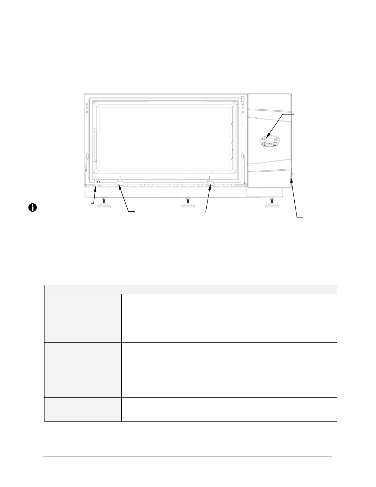
2.1 Front View
This drawing is for reference, to acquaint you with the user interface controls:
Figure 1: Front View
USER
INTERFACE
(display,
indicator lights
& keypad
)
Door is open
2.2 Specifications
These specifications assume a maximum load of 34 pounds (15.5 kg), including
platforms, clamps, glassware and contents.
SHAKING
Speed
Control Accuracy
Indication
Stroke/Orbit
TEMPERATURE
I-26 Range
I-26R Range
Control Accuracy
Indication
Heaters
ALARMS
Single unit: 25-400 rpm
2 or 3 units stacked: 25-250 rpm
1 rpm
3 Digit LED, in 1 rpm increments
2.5 cm (1 in)
5°C above ambient temperature to 60°C
15°C below ambient (minimum 4°C) to 60°C
0.1°C from 30-40 °C, 0.5°C over the remaining range.
3 Digit LED, in 0.1°C increments
Long-life, low-watt density resistance-type heaters with high
temperature thermostats
Visible and audible warning indication when speed deviates more
than 5 rpm or temperature more than 1°C from setpoints, and when
timer has expired. Audible alarm can be muted.
PLATFORM RESTS
on back of door
I-26/26R Incubator Shaker
...continued...
ON/OFF Switch
I-26/26R Incubator Shakers M1324-0050 Operating Manual
Page 9

9
I-26/26R Incubator Shaker
LED DISPLAY
RS 232
SETPOINT
RETENTION
AUTOMATIC
RESTART
STACKING
DRIVE
DRIVE MOTOR
SAFETY
ELECTRICAL
REQUIREMENTS
SAFETY
REGULATORY
STANDARDS
CE REGULATORY
STANDARDS
OVERALL
DIMENSIONS
Width
Depth (Front to Back)
Height (excluding
optional base)
CHAMBER
DIMENSIONS
PLATFORM
WEIGHT
FUSES
Indicates speed, temperature, running time alarm conditions, and
displays readout of internal clock (actual accumulated operating
time). Character height: 14.3 mm (9/16 in)
Provides access for remote data logging
All setpoints and operating status are retained in non-volatile
memory
Automatic restart after power is restored, indicated by flashing
display
Up to three units may be stacked; the second and third units require
stacking kit(s).
Triple-eccentric counterbalanced drive with nine permanently
lubricated ball bearings
Solid-state brushless DC motor.
An independent mechanical sensing “tilt switch” shuts off the motor
in an unbalanced condition. Drive Interrupt shuts off power to shaker
when door opens. Acceleration/deceleration circuit prevents sudden
starts and stops, minimizing both splashing and mechanical
damage.
100 Volts, 50/60 Hz
120 Volts, 60 Hz
230 Volts, 50 Hz
UL61010A-1
UL61010-2-010
See DECLARATION OF CONFORMITY
Single Unit
128.3 cm (50.5 in)
77 cm (30.32 in)
70 cm (27.56 in)
86.4 cm (34 in) Wide X 58.4 cm (23 in ) Deep X 39.4 cm (15.5 in)
High clearance above platform
Aluminum, 46 cm X 76 cm (18 in X 30 in)
I-26: 167.8 kg (370 lbs)
I-26R: 181.5 kg (400 lbs)
Two 8.0A 250V, Slo-Blo
Two Units
128.3 cm (50.5 in)
77 cm (30.32 in)
133.5 cm (52.56 in)
®
I-26: 800 VA per shaker
I-26R: 1500 VA per shaker
CAN/CSA-C22.2 No 1010.1
CAN/CSA-C22.2 No 1010.2.010
Three Units
128.3 cm (50.5 in)
77 cm (30.32 in)
197 cm (77.56 in)
2.3 Certifications
The I-26 and I-26R have been tested to comply with UL and CAN/CSA electrical safety
standards (see “Safety Regulatory Standards” in the specifications table). As attested in
the CE Declaration of Conformity reproduced on the following page, they also conform
to the appropriate EU standards.
New Brunswick Operating Manual
Page 10

10
I-26/26R Incubator Shakers M1324-0050 Operating Manual
Page 11
11
N
33
I
NNSSPPEECCTTIIOON
I
,
,
V
EERRIIFFIICCAATTIIOONN
V
&
&
U
NNPPAACCKKIINNGG OOFF
U
3.1 Inspection of Boxes
After you receive your order from Eppendorf/New Brunswick, inspect the boxes
carefully for any damage that may have occurred during shipping. Report any damage to
the carrier and to your local New Brunswick or Eppendorf Sales Order Department.
3.2 Packing List Verification
Verify against your packing list that you have received the correct materials.
3.3 Unpacking of Equipment
CRUSH WARNING!
Do not attempt to lift the I-26/26R by hand.
Always use a lifter or other suitable equipment when raising or handling
the shaker.
E
QQUUIIPPMMEENNT
E
T
To unpack your I-26/26R, you will need the following:
Hammer
Forklift or other lifting equipment to lift 168 kg (370 lb) or more
Shears to cut 12.7 mm (½ in)wide plastic strapping
Tool to remove 7.6 cm (3 in) metal staples
If any part of your order was damaged during shipping, is missing, or fails to operate, fill
out the "Customer Feedback" online at www.nbsc.com/CustomerFeedback.aspx or call
Eppendorf/New Brunswick or your distributor's service department.
New Brunswick Operating Manual
Page 12

12
44
4.1 Physical Location
It is essential that the instrument be situated in an area where there is sufficient space for
the shaker and platform to clear walls and obstructions during operation. The surface on
which the unit is placed must be smooth, level, and able to support the shaker under full
load operating conditions.
CRUSH WARNING!
Do not attempt to lift the I-26/26R by hand.
Always use a lifter or other suitable equipment when raising or handling
the unit.
4.2 Environment
The shaker is designed to operate optimally in the following ambient conditions:
5º to 35°C
20 to 80% Relative Humidity non-condensing
P
RREEPPAARRIINNGG TTHHEE
P
L
OOCCAATTIIOON
L
N
4.3 Electrical Requirements
100, 120 or 230 VAC (depending on your selection)
800 VA for each I-26, 1500 VA for each I-26R
I-26/26R Incubator Shakers M1324-0050 Operating Manual
Page 13

13
4.4 Space Requirements
Figure 1a: Dimensions
DEPTH:
77 cm
30.32 in
DOOR
EXTENSION:
48.4 cm
19.05 in
WIDTH: 128.3 cm
50.5 in
HEIGHT:
70 cm
27.56 in
DOOR WIDTH:
99.5 cm
39.16 in
Be sure to allow four inches (10 cm) around the shaker for proper ventilation, and 24
inches (61 cm) on the right side for service access to fan and refrigeration assemblies.
New Brunswick Operating Manual
Page 14

14
55
I
NNSSTTAALLLLIINNGG TTHHEE
I
CRUSH WARNING!
Do not attempt to lift the I-26/26R by hand.
Always use a lifter or other suitable equipment when raising or handling
the unit.
5.1 Tools Required for Installation
To install the I-26/26R on an optional base and/or to stack I-26/26R units, the following
tools will be needed:
Number 2 Phillips head screwdriver
Level, 25.4 cm (10 in)
Two adjustable wrenches
Forklift or other lifting equipment to lift more than 168 kg (370 lb)
Metal leveling shims
II--2266//2266RR
5.2 Leveling a Single Shaker
Do NOT use feet if you are stacking shakers or adding a base.
Make sure that the shaker is placed on a level surface and that all four feet are solidly on
the surface. If the shaker is not level, adjust the feet as needed to achieve leveling:
1. Immobilize the top lock nut against the unit with one wrench whenever you adjust
the foot, to keep the threaded stud from falling out.
Figure 2: Adjustable Foot
BOTTOM OF
UNIT
FOOT
LOCK NUT
FLATS FOR WRENCH
I-26/26R Incubator Shakers M1324-0050 Operating Manual
Page 15

15
2. With a second wrench against the flats of the threaded stud, just above the foot:
rotate clockwise to lower the foot or counter-clockwise to raise the foot.
3. Place a level on the top of the unit.
4. If necessary, make further adjustments by repeating all steps until the unit is level.
5. Fully load the shaker, and do a test run at normal speed. Make additional leveling
adjustments if necessary.
The maximum foot height adjustment is ~ 6.4 mm (¼ in). If a higher
adjustment is required, you will need to add metal shims.
5.3 Adding a Base
There are three bases available for your I-26/26R shaker(s). The height of the base
depends on whether you are installing one unit on the base, or stacking two or three units:
Table 1: Optional Bases
Number of Shakers Base Height
43.2 cm (17 in)
1
2 stacked 33.0 cm (13 in)
3 stacked 10.2 cm (4 in)
One 10.2 cm (4 in) base & one 33.0 cm (13 in) base,
bolted together at the factory
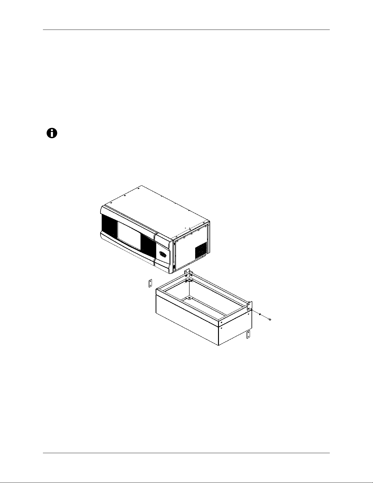
5.4 Preparing the Optional Base
1. Place the base on a sturdy (capable of bearing the weight of the combined base
shakers and shaker contents), level surface, making sure that all four corners are
solidly on the surface.
2. If the base is not level, place metal shims as needed under the base until it is level.
3. If you are mounting a single shaker, use the 43.2 cm (17 in) base as shown in Figure
3b. Bolt the shaker to the base using the hardware provided.
New Brunswick Operating Manual
Page 16

16
Figure 3a: Optional Short Base, 10.2 cm (4 in)
REAR CORNER
BRACE
10.2 cm (4 in)
BASE
FRONT SIDE BRACE
Figure 3b: Optional Tall Base, 43.2 cm (17in)
BASE MATING SUPPORTS
33 cm (13 in) BASE
4. As shown in Figures 3a-b, depending on the height of your base, install the front side
braces and rear corner braces on the base with the hardware provided, matched to the
holes in the base.
I-26/26R Incubator Shakers M1324-0050 Operating Manual
Page 17
17
5.5 Mounting the I-26/26R on the Optional Base
1. Using a forklift or lifter, raise the I-26/26R so that its back end is tilted toward the
rear of the base.
2. Remove all six feet from the bottom of the shaker. They will not be needed for
stacking, but you may want to keep them for future use.
3. With two assistants, each holding the shaker on one side, lower the unit onto the base,
rear panel first. Slowly and gently remove the forklift or lifter and lower the front of
the unit onto the base by hand.
Optional handles are available to facilitate maneuvering the shaker onto the
base. See Section 10.3.7 for details.
Figure 4: Mounting Shaker on Base
4. Using the ½-13 x 1¼-inch Allen head screws, ½-inch lock washers, and washers
provided, secure the rear of the I-26/26R to the corner braces in the base. With the
remaining ½-13 x 1¼-inch Allen head screws, ½-inch lock washers, and washers,
attach the front corner braces to the unit.
5. Attach the front corner braces to the base using the two sets of ½-13 x 1¼-inch Allen
head screws, lock washers, and washers provided, and secure as shown in Figure 5.
New Brunswick Operating Manual
Page 18

18
Figure 5: Mounting Corner Braces
With the corner braces securely in place, the shaker mounted on its base will look like
this:
Figure 6: Shaker Installed on Base
6. Make sure the shaker is level; add metal shims under the base as needed to level the
unit.
7. Fully load the shaker and do a test run at normal speed. Make additional leveling
adjustments if necessary.
I-26/26R Incubator Shakers M1324-0050 Operating Manual
Page 19

19
5.6 Installing the I-26/26R Stacking Kit
CAUTION!
If the shaker you will place on the bottom is already mounted on a 43.2 cm
(17 in) base, follow these instructions first:
To stack two shakers: (1) remove the 10.2 cm (4 in) high section of the base,
(2) remove the base mating supports, (3) move the corner braces from the
10.2 cm base to the 33.0 cm (13 in) base, (4) reinstall the shaker on the
33.0 cm base.
To stack three shakers: (1) remove the 33.0 cm (13 in) high section from the
bottom of the base, (2) remove the base mating supports.
1. Remove the six ½-inch plastic slotted set screws and the three ¼-inch plastic socket set
screws from the top of the shaker installed on the base.
Figure 7: Preparing to Stack Shakers
2. Using the six ½-13 x 1-inch hex head screws, lock washers, and washers provided,
attach the stacking kit stacking rails to the top sides of the unit installed on the base.
Secure the rails in place as shown in Figure 8.
3. Install the stacking stop bracket to the top back of the unit installed on the base, using
the three ¼-20 x 5/8-inch hex head screws, lock washers, and washers provided, as
shown in Figure 8 on the following page.
New Brunswick Operating Manual
Page 20

20
STOP BRACKET
Figure 8: Installing Stacking Kit Brackets
STACKING RAILS
5.7 Stacking the I-26/26R
1. Using a forklift or lifter, raise the I-26/26R to be stacked so that its back end is tilted
toward the rear of the mounting brackets.
2. Remove the feet from the unit. They will not be needed for stacking, but you may
want to keep them for future use.
3. With two assistants, each holding the unit on one side, lower the shaker onto the
mounting brackets, rear panel first. Slowly and gently remove the forklift or lifter
and lower the front of the unit onto the mounting brackets by hand.
Figure 9: Stacked Shakers
Fasten upper shaker
to stacking rails on
both sides and to the
rear stop bracket.
I-26/26R Incubator Shakers M1324-0050 Operating Manual
Page 21

21
4. As indicated in the above drawing, secure the bottom of the upper I-26/26R to the
side stacking rails using the six ½-13 x 1-inch screws, lock washers, and washers
provided. Also secure the upper unit to the stop rail using three ¼-20 x 5/8-inch hex
head screws, lock washers and washers.
5. As before, make sure the shakers are level; add metal shims under the base if needed.
6. Fully load the shaker and do a test run at normal speed. Make additional leveling
adjustments if necessary.
5.8 Stacking a Third I-26/26R
CAUTION!
Be sure to use the 10.2 cm (4 in) base only when you stack 3 shakers.
ALERT!
When stacking 3 shakers, it is imperative that all shaker loads be balanced.
These shakers operate best at maximum speed with a load of 15.5 kg 1.4
kg (34 lbs, 3 lbs), which includes all platforms, clamps, and filled
glassware. (See Load & Speed graphs in Section 5.8.1 for more information)
To stack a third shaker, repeat the procedures in sections 5.6 and 5.7 to install the
stacking kit, stack the shaker, and level the entire assembly.
5.8.1 Load and Speed Graphs
Figures 9a and 9b, show the maximum recommended speed for unstacked and
stacked shakers, according to load.
New Brunswick Operating Manual
Page 22

22
Figure 9a: Load & Speed for One Unstacked Shaker
400
350
300
250
200
150
Maximum Recommended Speed (RPM)
100
50
0
<30 30 to 36 36 to 40 40 to 60 >60
50,
125 ,
250 mL
20 % Ful l
Pl atfo rm and L oad (lb)
1L ,
2L ,
2.8L
20% Full
In both Figures 9a and 9b, “20% Full” refers to the amount of liquid in the
flasks. The platforms are fully loaded with flasks.
Figure 9b: Load & Speed for Stacked Shakers
250
200
150
50,
125,
100
Maximum Rec omm ended Sp ee d (RP M)
50
0
<30 30 to 36 36 to 40 40 to 60 >60
250 mL
20% Full
Platf orm a nd Load ( lb)
1L ,
2L ,
2.8L
20% Full
I-26/26R Incubator Shakers M1324-0050 Operating Manual
Page 23

23
6.1 Keypad
STATUS
INDICATORS
Figure 10: Keypad
66
F
EEAATTUURREES
F
DISPLAY
USER
INTERFACE
KEYS
S
6.2 LED Display
The digital display on the control panel is a three-digit LED DISPLAY. During normal
shaker operation, the display will indicate:
Shaker status (On/Off)
Shaking speed
Chamber temperature
Setpoints
Hours remaining (in a timed run)
Door (“
In addition, if the shaker should enter into an unstable operating condition (unbalanced
load causing excess vibration, unlevel floor, etc.), the warning message “tLt” will appear
in the LED display and the tilt switch will shut the shaker off.
LId”) open
New Brunswick Operating Manual
Page 24

24
6.3 User Interface Keys
START/STOP
SELECT
▲ (UP), ▼(DOWN)
6.4 Status Indicators
Four status indicator lights are located to the left of the LED DISPLAY. They are:
SET
POWER
HEAT
TIME
This key is used to start or stop the shaker. It will
also activate or stop the timer when a timed run is
desired.
This key is used to change the displayed parameter.
These keys are used to adjust the setpoint of a
displayed parameter up or down. They also allow
the user to enter the SET MODE for setpoint
changes.
Indicates that the shaker is in the SET MODE,
when setpoints are being displayed and can be
altered. This is activated by the SELECT key
or by pressing the ▲(UP), ▼(DOWN) arrow.
Illuminates and blinks during power up or if
power is interrupted during a run. Press the
SELECT key and change to another function to
turn off this indicator.
Illuminates to indicate that the heater is on.
Indicates that the timer is in operation. The
shaker can be programmed to run for a preset
time from 0.1 to 99.9 hours. The timer can be
disengaged without stopping an ongoing run.
I-26/26R Incubator Shakers M1324-0050 Operating Manual
Page 25

25
6.5 Function Indicators
Four function indicator lights are located to the right of the LED DISPLAY. They indicate
the current parameter(s) being displayed:
C
Interior chamber temperature. Can be set from
4°C to 60°C, when in SET MODE, using the
▲(UP), ▼(DOWN) arrow key. It indexes at
0.1°C increments unless the key is pressed for
4 seconds, after which it indexes in 1°C
increments.
RPM
Revolutions per minute. When in
SET MODE,
use the ▲(UP), ▼(DOWN) arrow key to change
the speed. It indexes at 1 RPM increments
unless the key is pressed for 4 seconds, after
which it indexes by increments of 10 RPM.
HRS
Time remaining in a timed run. Can be set
from 0.1 to 99.9 hours, in 0.1 increments or, if
the ▲(UP), ▼(DOWN) arrow key is pressed for
4 seconds, in increments of 5 hours.
The countdown begins when the START/STOP
key is pressed. If the START/STOP key is
pressed again, the shaking stops (but
temperature is maintained) and the timer
pauses until the START/STOP key is pressed
again.
When a timed run ends, the HRS indicator will
blink. Press the
SELECT key and change to
another function to turn off this indicator.
MUTE
This feature is controlled by the SELECT key.
When activated, the audible alarm is muted,
remaining so until it is reactivated. If
MUTE is
activated when the shaker is turned off using
the
ON/OFF switch, MUTE will be engaged
when it is powered up again. To activate (or
deactivate) the
SELECT key until the MUTE indicator
MUTE function, press the
illuminates; press the ▲ or ▼ KEY to display
ON or OFF, as desired; then press SELECT.
New Brunswick Operating Manual
Page 26

26
77
7.1 Platform Assemblies
The I-26/26R can be used with a New Brunswick universal, dedicated, or Sticky Pad
platform. Universal platforms accept a variety of clamps for flasks, test tubes, etc.
Dedicated platforms are supplied with clamps already installed. Sticky Pad platforms do
not have holes because they do not require clamps; the adhesive quality of the Sticky Pad
or Sticky Tape applied to the platform holds flasks in place.
Sticky Pad and Sticky Tape are options that are sold separately.
A platform is a separate item, not included with the shaker assembly, but which is
required for operation. (See Section 7.3 for details about installing and removing
the platform, and Section 10.3 for details about available accessories.)
7.2 Installation of Clamps
If you are not using a New Brunswick Universal Platform, skip this section. Flask
clamps purchased for use with universal platforms require installation. All New
Brunswick clamps are shipped complete with hardware. Clamps are installed by securing
the base of the clamp to the platform with the smaller Phillips head (+) screws supplied
with the New Brunswick clamps.
Clamps for 2- and 2.8-liter flasks are shipped with an additional girdle to keep the flasks
in place. We strongly recommend the use of this additional girdle because it keeps the
flask from spinning inside the clamp. The girdle is an assembly of springs and sections
of rubber tubing. One girdle is already in place on the clamp, the other is packed
separately. To install these double girdle clamps:
1. Place the clamp on the platform, aligning its mounting holes with holes on the
platform. Secure the clamp in place using the flat Phillips head screws provided
(#S2116-3051, 10-24 x 5/16-inch); see Figure 11b to help you identify them.
2. With the first girdle in place, as delivered, on the upper part of the clamp body (see
Figure 11a), insert an empty flask into the clamp.
3. After making sure the sections of tubing are located between the clamp legs, roll the
first girdle down the legs of the clamp as far as it can go. The tubing sections will
rest against the platform, and the springs will be under the clamp base.
4. Place the second girdle around the upper portion of clamp body (just as the first
girdle was initially). Make sure that its spring sections rest against the clamp legs,
while its rubber tubing sections sit against the flask, in between the clamp legs.
G
EETTTTIINNGG
G
S
TTAARRTTEED
S
D
I-26/26R Incubator Shakers M1324-0050 Operating Manual
Page 27

27
Figure 11a: 2- & 2.8-Liter Clamp Installation
CLAMP
MOUNTING
HOLES (5)
UPPER GIRDLE
WITH GIRDLE
TUBES
LOWER
GIRDLE WITH
GIRDLE TUBES
CLAMP BODY
(LEGS AND BASE)
Figure 11b: Clamp Fastener
The upper girdle secures the flask within the clamp, and the bottom girdle
keeps the flask from spinning.
7.3 Installing/Sliding out Platform
The I-26/I-26R is delivered with the subplatform bolted in place on the bearing housing.
The addition of a platform is required for shaker operation.
Installing a platform of any variety is very easy:
1. Remove the two knobs and washers on the front of the subplatform.
2. Using the side handles of the platform (see Figure 12), place the platform on the
guide strips on the flat of the open door.
3. Push it toward the rear of the unit, aligning the bottom of the platform with the top of
the subplatform, and making sure the sides are squared up with the subplatform sides.
4. When it is fully inserted and mated to the subplatform, replace the washers and knobs
on the subplatform.
New Brunswick Operating Manual
Page 28

28
5. Verify that the platform is now secured to the subplatform and the drive.
Figure 12: Installing Platform
PLATFORM
KNOB
SUBPLATFORM
All platforms, once installed, will easily slide in and out of the shaker:
1. Unscrew both knobs and remove the knobs and the washers on the front of the
platform to release the platform from the subplatform.
2. Pull the platform forward to rest on the door guide strips. The two stop pins in the
door will keep the platform from falling off the subplatform.
3. Slide it back in and be sure to replace the washers and knobs before operating the
shaker again.
7.4 Electrical Connections
Before making electrical connections, verify that the power source voltage matches the
voltage on the ELECTRICAL SPECIFICATION PLATE and that the ON/OFF SWITCH is on
OFF position. The ELECTRICAL SPECIFICATION PLATE is located on the rear panel
the
of the unit near the POWER CONNECTOR.
I-26/26R Incubator Shakers M1324-0050 Operating Manual
Page 29

29
Connect the POWER CORD to the POWER CONNECTOR (Universal Voltage Input
Module), then connect the other end to a suitable, grounded receptacle.
Figure 13: Rear Panel
POWER
CONNECTOR
ELECTRICAL
SPECIFICATION
PLATE
ON/OFF
SWITCH
New Brunswick Operating Manual
Page 30

30
8.1 Starting the Shaker
To initially start the shaker, close the door and turn the ON/OFF SWITCH on the right side
panel of shaker to the ON position. When the shaker begins to operate, the LED DISPLAY
will track the speed as it accelerates to the last entered setpoint. The shaking action may
be started or stopped by pressing the
Figure 14: ON/OFF Switch Location
88
START/STOP KEY on the KEYPAD.
O
PPEERRAATTIIOON
O
KEYPAD
N
DOOR HANDLE (cut-
out under rim)
ON/OFF SWITCH
The shaker will not operate if the door is open. This is indicated by the word
LId appearing in the LED DISPLAY.
I-26/26R Incubator Shakers M1324-0050 Operating Manual
Page 31

31
8.2 Continuous (Unlimited) Run
1. Press SELECT until the RPM INDICATOR is illuminated.
2. If the display indicates that the shaker is OFF, press the START/STOP KEY.
3. Press either
▲(UP), ▼(DOWN) KEY to enter SET MODE (the SET INDICATOR will
illuminate).
4. Set the speed by using the
▲ or ▼ KEY until the desired setpoint is displayed.
Continued pressure on the ▲ or ▼ KEY will cause the setting to change more rapidly.
The setpoint may be changed during a run without stopping the shaker by
following steps 1-4 above.
8.3 Checking Any Setpoint
1. Press SELECT until the desired indicator is illuminated.
2. Briefly press either the ▲ or ▼ KEY to enter the SET MODE and display the current
setpoint.
Holding the ▲ or ▼ for more than 0.5 seconds causes the speed
setpoint to change. Should this occur, resetting will be necessary.
8.4 Timed Functions
The shaker may be programmed to automatically stop after a preset time period of 0.1 to
99.9 hours. There must be power to the shaker in order to set the timer, although a timed
run can be initiated while the unit is either stopped or operating.
To set the timer:
1. Press the
2. Press either
SELECT KEY until the HRS INDICATOR is illuminated.
▲ or ▼ KEY to enter the SET MODE and set the desired run time, between
0.1 and 99.9 hours.
If the shaker is stopped, skip to Step 5 below. If the shaker is already running:
3. Press the
START/STOP KEY. The shaker will stop and the display will read OFF.
4. Press the START/STOP KEY again; the TIME INDICATOR will light and the shaker will
start the timed run.
If the shaker is stopped:
5. Press the START/STOP KEY. The shaker will start in untimed mode.
New Brunswick Operating Manual
Page 32

32
6. Press the START/STOP KEY again. The shaker will stop and the display will read
OFF.
7. Press the START/STOP KEY a third time; the TIME INDICATOR will light and the
shaker will start the timed run.
To disable the visual alarm (flashing TIME INDICATOR), press the SELECT KEY and
change to any other function.
To cancel the timer while the shaker is running:
1. Press the SELECT KEY until the HRS indicator lights.
2. Press the
will read
▼ KEY until 0.0 is displayed, then press the START/STOP KEY. The display
OFF, the shaker will stop, and the TIME INDICATOR light will turn off.
3. Press the START/STOP KEY to continue in untimed mode.
To cancel the timer while the shaker is stopped:
1. Press the ▼ KEY until 0.0 is displayed, then press the START/STOP KEY. The TIME
INDICATOR
will light and the shaker will run.
2. Press the START/STOP KEY. The shaker will stop and the TIME INDICATOR will turn
off.
3. Press the START/STOP KEY a third time, and the shaker will run in untimed mode.
8.5 Alarm Functions
The I-26/26R shakers have an audible alarm which is activated at predetermined times.
It can be deactivated by using the MUTE function:
1. Press the SELECT key until the MUTE indicator illuminates.
2. Press the
▲ or ▼ KEY to display ON, then press the SELECT KEY.
To reactivate the audible alarm:
1. Press the SELECT key until the MUTE indicator illuminates.
2. Press the ▲ or ▼ KEY to display OFF, then press the SELECT KEY.
There is also a visual “tilt” alarm; see Section 8.10 for details.
I-26/26R Incubator Shakers M1324-0050 Operating Manual
Page 33

33
8.6 Temperature Setpoint
Press the SELECT KEY until the function C INDICATOR illuminates. The temperature can
be set from 5C above ambient temperature to 60C (non-refrigerated units) or from 4C
to 60C (refrigerated units). Increasing or decreasing the setpoint is accomplished with
the ▲ or ▼ KEY. Ambient temperature is measured one meter from the front of the unit.
During operation, if the temperature of the chamber is more than 1.0C higher or lower
than the temperature setpoint, an alarm is triggered. This alarm consists of a flashing C
INDICATOR
achieves the set temperature.
8.7 Temperature Offset Calibration
The temperature probe and the temperature controller are calibrated together at the
factory. The temperature probe measures the temperature of the air at the probe’s
location, near the heat exchanger return vent. The controller uses the probe input to
adjust air temperature, up or down, to match the temperature setpoint.
Depending on various conditions within the chamber, such as flask placement and size,
the heat produced by growing organisms, heat losses due to liquid evaporation from
flasks, etc., the display temperature may differ from temperatures within the flasks
themselves.
If you wish to have the temperature display (“Indicated Temperature”) match the
temperature at a given point, or match the average of a series of points within the
chamber (“Actual Temperature”), proceed as follows:
1. Let the unit equilibrate at or near the desired temperature. Record the Indicated
Temperature.
2. Record the Actual Temperature.
3. Calculate the temperature correction value: Actual Temperature – Indicated
Temperature = Temperature Correction Value.
4. Press the
5. Simultaneously press the ▲ or ▼ KEY. The display will indicate CAL.
6. Using the
above.
7. Simultaneously press the
memory.
and audible beep. The alarm will automatically deactivate as the unit
SELECT KEY until the function C INDICATOR illuminates.
▲ or ▼ KEY, enter the Temperature Correction Value calculated in Step 3
▲ or ▼ KEY to save the Temperature Correction Value to
New Brunswick Operating Manual
Page 34

34
The °C light will pulse rapidly to indicate it is not operating in the factory
default mode. It will pulse for a longer duration and less rapidly (with a
frequency of approximately one second) to indicate temperature is more
than one degree above or below setpoint.
To return to the factory calibration:
1. Press the SELECT KEY until the function C INDICATOR illuminates.
2. Simultaneously press the ▲ or ▼ KEY. The display will indicate CAL.
3. Using the ▲ or ▼ KEY, set the Temperature Correction Value to zero.
4. Simultaneously press the
▲ or ▼ KEY. The rapid pulsing of the C INDICATOR will
stop.
8.8 Power Failure
In the event of a power failure, the I-26/26R shakers are equipped with an automatic
restart function.
If the shaker was in operation prior to the power interruption, the shaker will begin to
operate at its last entered setpoint. The
LED DISPLAY will flash, indicating that a power
failure has occurred. Press any key to stop the flashing of the LED display.
8.9 Speed Calibration
To calibrate the shaking speed:
1. Set the shaker to a speed that can easily be measured. If you are using a strobe,
minimum speed should be 250 RPM.
2. Compare the reading on the display to the measured reading.
If an adjustment is needed:
1. Press the
2. Press the
SELECT KEY until the RPM indicator light illuminates.
▲ or ▼ KEYS simultaneously. The display will indicate CAL.
3. Press either the ▲ or ▼ KEY to change the displayed value to match the measured
speed.
4. Press the▲ or ▼ KEYS simultaneously to save the adjustment.
5. Turn unit
OFF using the power switch, then turn it back ON.
8.10 Tilt Switch
I-26/26R Incubator Shakers M1324-0050 Operating Manual
Page 35

35
The shaker is equipped with an independent mechanical sensing tilt switch that shuts off
the motor when it senses that the shaker is in an unbalanced condition, indicating tLt
(“tilt”) on the LED display.
When this happens, troubleshoot the situation to restore balance, then turn the power
switch OFF, then ON again to reset the system.
New Brunswick Operating Manual
Page 36

36
99
ELECTRICAL SHOCK WARNING!
When performing maintenance on the unit, always turn off the shaker
and disconnect the power cord from the power supply.
9.1 Cleaning External Surfaces
The unit may be cleaned using a damp cloth or any standard household or laboratory
cleaner to wipe down its outer surfaces. Do not use abrasive or corrosive compounds to
clean this instrument, as they may damage the unit and void the warranty.
9.2 Fuse Replacement
I-26 models require one 8-amp electrical fuse, which is housed in the fuse holder located
on the M1324-7004 PCB (see Figure 15d). I-26R models have two 8-amp electrical
fuses, housed in the two fuse holders located on the M1324-7003 PCB (see Figure 15e).
To check or replace a fuse:
1. Set the ON/OFF SWITCH to Off and disconnect the POWER CORD from the power
source.
2. Remove the front right bezel from the shaker: with one hand, grasp the top edge, and
with the other, using the cut-out provided on the bottom, grasp the bottom edge. Pull
the bezel up from the bottom, then out and away. Set it aside.
3. With reference to Figure 15a, remove the two screws that fasten the electrical panel
in place. Set the screws aside for reuse.
Figure 15a: Front Bezel Removed
P
P
RREEVVEENNTTIIVVEE
M
M
AAIINNTTEENNAANNCCE
Remove
screws
E
ELECTRICAL
PANEL
I-26/26R Incubator Shakers M1324-0050 Operating Manual
Page 37

37
4. Swing the ELECTRICAL PANEL to the right to access the PCB board that houses the
fuse(s); see Figures 15b (I-26) and 15c (I-26R).
Figure 15b: Rear of Electrical Panel (I-26)
FUSE HOLDER
(see Figure 15d for details)
Figure 15c: Rear of Electrical Panel (I-26R)
FUSE HOLDERS
(see Figure 15e for details)
New Brunswick Operating Manual
Page 38

38
Figure 15d: Fuse Holder Detail (I-26)
FUSE
Figure 15e: Fuse Holder Detail (I-26R)
FUSES
5. Remove the fuse and check it. If it has failed, replace the fuse.
6. Swing the
ELECTRICAL PANEL to the left, flush against the unit.
7. Using the screws set aside, fasten the ELECTRICAL PANEL in place.
8. With two hands, reinstall the front bezel, snapping the top in place first, then the
bottom. Verify that it fits snugly and securely.
I-26/26R Incubator Shakers M1324-0050 Operating Manual
Page 39

39
9.3 Belt Replacement
To gain access to the drive belt, your service technician will follow these steps with
reference to Figures 16, 16a & 17:
1. Make sure that the power is switched off and the shaker is unplugged.
2. For safety and to facilitate removal of the drive assembly, using a Phillips head
screwdriver, follow these steps with reference to Figure 16 to remove the door (save
all hardware for reuse):
a. Remove the brackets that hold the door to its check latches.
b. Remove the gas shock bracket.
c. Carefully close the door so the latches are holding the door closed.
d. Unscrew the hinge from the base of the shaker.
e. Remove the door.
Figure 16: Removing the Door
DOOR LATCH
GAS SHOCK
BRACKET
DOOR CHECK
LATCH BRACKET
3. Remove the platform.
4. With reference to Figure 16a on the following page, remove the drive assembly
following these steps:
a. Using a 7/32-inch Allen key (hex wrench), remove the four bolts that hold the
subplatform in place, and remove the subplatform.
b. Disconnect the motor by unplugging its connector.
New Brunswick Operating Manual
Page 40

40
c. With a wrench, remove the nuts that hold the bearing housing to the bottom
weldment.
d. Position the counterweight so it is closest to you, and tie it in place with tie wraps
or strong cord, in order to prevent it from dropping against your fingers or
causing you to lose your grip.
e. Remove the bearing housing with care: it weighs 21.3 kg (47 lbs).
Figure 16a: Removing the Drive Assembly
SUBPLATFORM
BOTTOM
WELDMENT
BEARING
HOUSING
5. Turn the bearing housing over to access the belt, motor and pulley.
To replace the drive belt, follow these steps with reference to Figure 17 on the
following page:
1. Loosen the four hex nuts that hold the motor assembly in place and remove the old belt.
2. Guide the belt onto the two pulley grooves.
3. Tighten the motor nuts.
4. Check the belt adjustment by applying finger pressure to the belt midway between the
two pulleys. The belt should deflect approximately 9-10 mm (3/8 in).
5. If the deflection is not right, loosen the nuts, readjust the belt, and retighten the motor
nuts.
I-26/26R Incubator Shakers M1324-0050 Operating Manual
Page 41

41
Figure 17: Belt Replacement & Adjustment
DRIVE BELT
PULLEY
BEARING
HOUSING
FOUR MOTOR FIXING BOLTS
(loosen for belt tensioning)
MOTOR
If an adjustment is required:
1. Loosen the four hex nuts on the motor assembly.
2. Move the motor assembly until the belt is tight.
3. Tighten the hex nuts and recheck the belt tension by exerting pressure on the belt.
The belt should deflect approximately 9-10 mm (3/8 in).
Reassembly:
1. In reverse order, reinstall the bearing housing. Once it is securely in place, remove
the tie wraps/cord.
2. Secure the wiring to ensure no interference during rotation.
3. Reinstall the subplatform and platform.
4. Recalibrate speed (see Section 8.9).
New Brunswick Operating Manual
Page 42

42
10.1 Troubleshooting
If any problems occur with your shaker, do not attempt to perform any service on the unit
other than specified in this manual. Unauthorized servicing may void the warranty.
Please contact your local Sales Order Department
In any correspondence with New Brunswick or Eppendorf, please refer to the Model
Number and Serial Number of your unit. This information is on the
SPECIFICATION PLATE
CONNECTOR
panel, below the chamber door seal.
There are some problems, however, that you can investigate and correct yourself. Refer
to the following Troubleshooting Guide:
Symptom(s) Probable Cause(s) & Solution(s)
Shaker does not run.
Shaker runs slowly
and/or no speed
indication.
. The Serial Number is also labeled in the lower right corner of the front
, located on the rear panel of the unit, above the POWER
S
1100
ELECTRICAL
No power; display is not on; power cord is not plugged in and/or
power switch is off: plug in power cord (to working electric
outlet), and turn on power switch.
Door is open: close door firmly, making sure latch is engaged.
Door is closed but not completely: door magnet is not adjusted
correctly; call for service.
On/Off switch is not working: call for service.
Tilt switch has been triggered. Check to ensure the load is
evenly distributed and that the shaker is level on a solid surface.
Restart by pressing the START/STOP button.
Fuse(s) burned out: check and replace as needed.
If you recently replaced a fuse, it may not have been seated
properly: remove and reinstall the fuse carefully.
Shaking speed has been set to Zero by program running or by
computer interface: reset shaking speed.
Defective main board: call for service
Defective display controller board: call for service.
Jammed shaking mechanism: check for debris; if necessary,
call for service
Defective motor: call for service
Drive belt out of alignment or worn: call for service.
If you recently replaced a fuse, it may not have been seated
properly: remove and reinstall the fuse carefully.
Incorrect speed calibration: recalibrate shaking speed.
Defective main board: call for service.
Defective tach board: call for service
Defective motor: call for service.
Drive belt is out of alignment or worn: call for service.
...continued...
EERRVVIICCE
S
E
I-26/26R Incubator Shakers M1324-0050 Operating Manual
Page 43

43
Symptom(s) Probable Cause(s) & Solution(s)
Shaker does not run at
set speed.
Incubator does not
reach set temperature.
indication.
Shaker is overloaded and/or you are using baffled flasks:
remove some contents & balance load.
Defective motor: call for service.
Drive belt out of alignment or worn: call for service.
Load out of balance: unload all contents, then reload. Operating noise
Loose component(s) in platform, subplatform and/or drive
assembly: call for service.
Heater fuse blown: replace.
Compressor fuse blown: replace.
Compressor over-pressure switch activated: call for service.
Ambient temperature too high or too low: cool or heat the room
as needed.
Defective heater: call for service.
Defective refrigeration system: call for service.
Incorrect temperature indication (see below).
Defective RTD assembly: call for service. Incorrect temperature
Defective main board: call for service.
10.2 Replacement Parts
When ordering replacement parts, or requesting service information, please provide the
Model Number and Serial Number of your shaker. This information is on the
ELECTRICAL SPECIFICATION PLATE, located on the rear panel of the unit. The Serial
Number is also labeled in the lower right corner of the front panel, below the chamber
door seal.
Part Description Qty Req’d Part Number
8.0A Fuse (Motor) 1 (I-26)
2 (I-26R)
15A Circuit Breaker 1 P0400-4305
120V 15A Power Cord 1 P0720-2024
220V Power Cord 1 P0720-2021
Poly-V Belt 1 P0700-7070
Gasket, Door 1 M1324-9508
Damper, Slam-Preventing (gas shock bracket) 2 P0640-0385
AC Connector, Power Entry 1 P0460-2205
Drive Assembly 1 M1324-5010
P0380-3790
Belt Replacement Hardware:
Part Description Qty Req’d Part Number
3/8-16 NC x 1¼-inch long flat head Allen
screw
3 S1127-3206
New Brunswick Operating Manual
Page 44

44
10.3 Accessories
When ordering accessories, please provide the Model Number and Serial Number of your
shaker. This information is on the ELECTRICAL SPECIFICATION PLATE, located on the
rear panel of the unit. The Serial Number is also labeled in the lower right corner of the
front panel, below the chamber door seal.
10.3.1 Available Platforms, 46 x 76 cm (18 x 30 in)
Dedicated Platforms include flask clamps, pre-installed:
Application Capacity Part Number
125 ml Erlenmeyer Flasks 60 M1324-9905
250 ml Erlenmeyer Flasks 40 M1324-9906
500 ml Erlenmeyer Flasks 24 M1324-9907
1 L Erlenmeyer Flasks 15 M1324-9908
2 L Erlenmeyer Flasks 12 M1324-9909
2.8 L Erlenmeyer Flasks 6 M1324-9910
A Sticky Pad Platform (P/N M1324-9911), eliminates the need for flask clamps.
Sticky Pad (P/N M1250-9700) sold separately.
A Universal Platform (P/N M1324-9904) provides maximum flexibility for
mixing various sized glassware on a single platform. Flask clamps, test tube racks
and accessories sold separately.
10.3.2 Flask Clamps for Universal Platforms
Clamp Size Part Number
10 ml Erlenmeyer Flask ACE-10S
25 ml Erlenmeyer Flask M1190-9004
50 ml Erlenmeyer Flask M1190-9000
125 ml Erlenmeyer Flask M1190-9001
250 ml Erlenmeyer Flask M1190-9002
500 ml Erlenmeyer Flask M1190-9003
1 L Erlenmeyer Flask ACE-1000S
2 L Erlenmeyer Flask ACE-2000S
2.8 L Fernbach Flask ACFE-2800S
10.3.3 Replacement Clamp Hardware Kits
New Brunswick Flask Clamps come complete with the proper hardware kits.
However, from time to time you may want to obtain some additional Hardware
Kits. The following table identifies the proper screws for your shaker application
by reference to the head style and size.
I-26/26R Incubator Shakers M1324-0050 Operating Manual
Page 45

45
Description Part Number Qty. Application
10-24 x 5/16 (7.9 mm) flat
Phillips head screw
S2116-3051 1 7.9 mm (5/16 in) thick
aluminum
10.3.4 Carriers and Test Tubes
Accessory Description Part
Adjustable angle Test Tube
Rack for tubes 8 – 11 mm
diameter
Adjustable angle Test Tube
Rack for tubes 12 - 15 mm
diameter
Adjustable angle Test Tube
Rack for tubes 15 –18 mm
diameter
Adjustable angle Test Tube
Rack for tubes 18 – 21 mm
diameter
Adjustable angle Test Tube
Rack for tubes 22 – 26 mm
diameter
Adjustable angle Test Tube
Rack for tubes 26 - 30 mm
diameter
Microplate holder rack
(stacked)
Microplate holder rack
(single layer)
Angled Test Tube Rack Holder* for user-supplied test tube
racks that are 4-5 in. (10-13 mm) wide and up to 15 in.
(38 mm) long.
Angled Test Tube Rack Spacer Bar* for use with TTR-210
to accommodate test tubes racks that are less than 5 in.
(13 mm) wide.
* Universal Platform Required
80 tube capacity M1289-0100 7
60 tube capacity M1289-0010 9
48 tube capacity M1289-0001 9
60 tube capacity M1289-0200 7
44 tube capacity M1289-0020 9
34 tube capacity M1289-0002 9
42 tube capacity M1289-0300 7
31 tube capacity M1289-0030 9
24 tube capacity M1289-0003 9
30 tube capacity M1289-0400 7
23 tube capacity M1289-0040 9
18 tube capacity M1289-0004 9
22 tube capacity M1289-0500 7
16 tube capacity M1289-0050 9
13 tube capacity M1289-0005 9
20 tube capacity M1289-0600 7
16 tube capacity M1289-0060 9
12 tube capacity M1289-0006 9
3 deep well or 9 standard M1289-0700 16
5 deep well or standard TTR-221 4
Number
TTR-210
TTR-215
Platform
Capacity
4
NA
10.3.5 Optional Bases for I-26/26R
Description Part Number
10.2 cm (4 in) Base (“Short Base”) M1324-0600
33.0 cm (13 in) Base (“Medium Base”) M1324-0800
43.2 cm (17 in) Base (“Tall Base”) M1324-0700
New Brunswick Operating Manual
Page 46

46
The 43.2 cm (17 in) Tall Base is made of the 10.2 cm (4 in) and 33.0 cm (13 in)
bases, bolted together at the factory.
10.3.6 Stacking Kit for I-26/26R
Description Part Number
Stacking hardware (to stack two units) M1324-0500
10.3.7 Optional Handles
Description Part Number
Screw-in handles (4 pieces in kit) M1282-5042
Each shaker has two threaded holes at the bottom of both side panels. You can
screw the optional handles into these holes. They are useful for lifting the shaker
onto an optional base, for example.
CRUSH WARNING!
Make sure that any persons who will use these handles (for minor
moves or lifts only) take proper precautions to protect their hands, feet
and backs from injury.
Do not use the screw-in handles to lift the shaker if it is fastened to a base.
I-26/26R Incubator Shakers M1324-0050 Operating Manual
Page 47

47
11.1 Control Schematics
Figure 18: Control Schematics, Overview
1111
D
D
WIINNGGSS
RRAAW
For a larger version of this drawing, contact your sales or service
representative.
New Brunswick Operating Manual
Page 48

48
230Vac/50Hz OPERATION
COND. FAN
ORANGE
M1324-8017
OVER PRESSURE
SWITCH
M1324-8016
COMPRESSOR
UNIT
Figure 19a: 230V Schematic
POWER
TRANSFORMER
M1324-8015
N
230V
100V
120V
TB001
RED
ORANGE
BLACK
WHITE
YELLOW
VIOLET
M1324-8001
BLUE
RED
WHITE
ORANGE
BLACK
BLACK
BLACK
1
BLACK
VIOLET
2
M1324-8017
FROM
M1324-7003
J4-1
J4-3
J4-5
J4-2
J4-4
J4-6
Figure 19b: 100V/60 Hz Schematic
100Vac/60Hz OPERATION
POWER
TRANSFORMER
M1324-8015
230V
100VN120V
TB001
COND. FAN
ORANGE
M1324-8017
OVER PRESSURE
SWITCH
M1324-8016
COMPRESSOR
UNIT
BLUE
RED
ORANGE
WHITE
BLACK
BLACK
BLACK
BLACK
1
VIOLET
2
M1324-8017
FROM
M1324-7003
ORANGE
BLACK
RED
WHITE
YELLOW
VIOLET
M1324-8001
J4-3
J4-5
J4-1
J4-2
J4-4
J4-6
I-26/26R Incubator Shakers M1324-0050 Operating Manual
Page 49

49
Figure 19c: 100V/50 Hz Schematic
100Vac/50Hz OPERATION
POWER
TRANSFORMER
M1324-8015
230V
100VN120V
FROM
M1324-7003
ORANGE
RED
BLACK
WHITE
YELLOW
VIOLET
M1324-8001
J4-3
J4-1
J4-5
J4-2
J4-4
J4-6
COND. FAN
ORANGE
M1324-8017
OVER PRESSURE
SWITCH
M1324-8016
COMPRESSOR
UNIT
BLUE
RED
ORANGE
WHITE
BLACK
BLACK
BLACK
M1324-8017
BLACK
1
VIOLET
2
TB001
Figure 19d: 120V Schematic
COND. FAN
ORANGE
M1324-8017
OVER PRES SURE
SWITCH
M1324-8016
COMPRESSOR
UNIT
120Vac/60Hz OPERATION
TB001
BLUE
BLACK
BLACK
1
BLACK
2
M1324-8017
VIOLET
FROM
M1324-7003
RED
ORANGE
BLACK
WHITE
YELLOW
VIOLET
M1324-8001
J4-1
J4-3
J4-5
J4-2
J4-4
J4-6
New Brunswick Operating Manual
Page 50

50
Figure 20: Refrigeration Diagram
I-26/26R Incubator Shakers M1324-0050 Operating Manual
Page 51

51
11.2 List of Drawings
Figure Description Page
1 Front View 8
1a Dimensions 13
2 Adjustable Foot 15
3a Optional 4-Inch Base 16
3b Optional 17-Inch Base 16
4 Mounting Shaker on Base 17
5 Mounting Corner Braces 18
6 Shaker Installed on Base 18
7 Preparing to Stack Shakers 19
8 Installing Stacking Kit Brackets 20
9 Stacked Shakers 20
9a Load & Speed for One Unstacked Shaker 22
9b Load & Speed for Stacked Shakers 22
10 Keypad 23
11a 2- & 2.8-Liter Clamp Installation 27
11b Clamp Fastener 27
12 Installing Platform 28
13 Rear Panel 29
14 ON/OFF Switch Location 30
15a Front Bezel Removed 36
15b Rear of Electrical Panel (I-26) 37
15c Rear of Electrical Panel (I-26R) 37
15d Fuse Holder Detail (I-26) 38
15e Fuse Holder Detail (I-26R) 38
16 Removing the Door 39
16a Removing the Drive Assembly 40
17 Belt Replacement & Adjustment 41
18 Control Schematics, Overview 47
19a 230V Schematic 48
19b 100V/60 Hz Schematic 48
19c 100V/50 Hz Schematic 49
19d 120V/60 Hz Schematic 49
20 Refrigeration Diagram 50
New Brunswick Operating Manual
Page 52

52
A
Abbreviations
Glossary of · 6
Accessories · 44
Actual Temperature · 33
Alarm Functions · 32
ALERT
Explanation of · 6
Audible Alarm
Disabling · 32
B
Base Part Numbers · 45
Base Sizes · 15, 45
Belt Replacement · 39
Belt Replacement Hardware · 43
C
Calibrating Speed · 34
Carriers · 45
CAUTION
Explanation of · 6
Symbol for · 3
Certifications · 9
Checking Setpoints · 31
Clamps
Installation of · 26
Continuous Run · 31
Control Schematics · 47, 48, 49
D
DANGER
Explanation of · 6
Declaration of Conformity · 9
Dimensions · 13
Drawing Index · 51
Drawings
List of · 51
1122
Flask Clamps · 44
Function Indicators · 25
Fuse
Replacement · 36
H
Handles · 17, 46
Hazard symbols · 6
I
Indicated Temperature · 33
Inspection
of Boxes · 11
Installing Clamps · 26
L
LED Display · 23
Leveling
Base (optional) · 15
One shaker, no base · 14
Shaker on base · 18
LId in Display · 23, 30
Load & Speed Graphs · 21, 22
M
Manual Conventions · 3, 6
N
NOTE
Symbol for · 3
NOTICE
Explanation of · 6
O
Operation · 30
Overview · 7
I
NNDDEEX
I
X
E
Electrical Connections · 28
Electrical Requirements · 12
Environment · 12
F
Features
Status Indicators · 24
I-26/26R Incubator Shakers M1324-0050 Operating Manual
P
Platform
Installing the · 27
Sliding the · 27
Platform Assemblies · 26
Platforms · 44
Power Failure · 34
Problems · 42
Page 53

53
R
Refrigeration Diagram · 50
Regulatory Standards · 9
Replacement Parts
Clamp Hardware Kits · 44
Replacement Parts · 43
S
Space Requirements · 13
Specifications · 8
Speed Calibration · 34
Stacking
Installing Hardware Kit · 19
Stacking Kit · 46
Starting the Unit · 30
Status Indicators · 24
T
Temperature Correction Value · 33
Temperature Offset Calibration · 33
Temperature Setpoint · 33
Test Tubes · 45
Tilt Switch · 7, 35
Timed Functions · 31
Timer
Cancelling the · 32
tLt in Display · 23, 35
Troubleshooting · 42
U
Unlimited Run · 31
User Interface Keys · 24
V
Visual Alarm
Disabling · 32
W
WARNING
Explanation of · 6
Symbol for · 3
New Brunswick Operating Manual
Page 54

54
I-26/26R Incubator Shakers M1324-0050 Operating Manual
 Loading...