

Page 1

Instructions
—
Galaxy® CO₂ Sensor SetupGalaxy® CO2 Sensor Setup
see
on p.Fig.Tab.p
.
I
nstructions
March 31, 2012
New Brunswick CO2 Incubators
Galaxy® CO
Sensor Setup
2
Instructions
CO2SENS-0060
Revision A
Page 2

Copyright
Copyright© 2012 New Brunswick Scientific Co., Inc., USA. No part of this publication may be reproduced without the prior
permission of the copyright owner.
New Brunswick reserves the right to change information in this document without notice. Updates to information in this
document reflect our commitment to continuing product development and improvement.
Trademarks
Eppendorf® is a registered trademark of Eppendorf AG, Germany.
New Brunswick and the New Brunswick Logo™ are trademarks of Eppendorf AG, Germany.
®
Galaxy
is a registered trademark of New Brunswick Scientific Co., Inc., USA.
WAGO® is a registered trademark of Kontakttechnic GmbH & CO. KG, Germany.
Pozidriv
®
is a registered trademark of Phillips Screw Company, USA.
Trademarks are not marked in all cases with ™ or ® in this manual.
New Brunswick has attempted to identify the ownership of all trademarks from public records. Any omissions or errors are
unintentional.
April 25, 2012
Revision A
CO2SENS-0060
Page 3
Galaxy® CO2 Sensor Setup — Instructions
1 Galaxy 170 R / 48 R 120 V / 230 V CO2 Incubators
1 Galaxy 170 R / 48 R 120 V / 230 V CO2 Incubators
1
1.1 K1 CO
Parts Supplied
1.3 m Tube, Silicone Rubber, Clear
12 Cable Tie, 2.5 x 100 Long
Sensor update kit retro fit instructions
2
1CO
1 Porous Sensor Cover, Sintered
1 Bracket Strain Relief
6 Washer, M3 Spring, A2 Stainless Steel
3 M3 Washer
3M3 Nut
3 M3 detector spacer 3.18 mm ID x 7 mm
2 Cable Tie, 2.5 x 100 Long
1Nut M4
1 Spacer 9.53 x 12.7 Long
1 Cable Tie Mount
1 M4 x 20 Pozidriv Screw
1 Spring, Tube Support
1 Solenoid Valve Assembly 24 VDC
1 Equipment Tray Cover Panel
2 M4 Washers
2
1 Bracket Self Adhesive Solenoid Valve
2 Self Adhesive Pads
1 IPA Cleaning Pad
1 Galaxy R-Plus Board 'Two'
2 EPROM ( Updated For Auto-Zero 1 off each model)
Sensor with Flying Leads and Connector Block
2
®
M4 x 6 Pozidriv
Screws
Galaxy 170 R / 48 R 120 V / 230 V CO
2
Incubators
3
Page 4

1
Incubators
2
Galaxy® CO2 Sensor Setup — Instructions
Tools required/recommended
Large sized Pozidriv screwdriver – for Equipment Tray and cover screws
Small sized Pozidriv screwdriver – for 170 R Expansion PCB screws
Side-Cutters – for cutting cable zip ties
5.5 mm nutspinner – for CO
5 mm nutspinner – for Expansion Board RS232 9 Way ‘D’ Connector fixing posts
T-bar torque limiter screw driver with attachment to fit M3 Hex
EPROM extractor tool or Small flat bladed screwdriver – to remove EPROM
ESD Wrist strap
1.2 Removing existing parts
Sensor M3 fixing nuts
2
1. Power down the Incubator and completely disconnect from the Mains/Power Supply. Open
the outer and Inner Door (option on 48 R) then remove the white porous cover on the CO2
Sensor from inside the chamber of the incubator (dashed red circle in image below).
Galaxy 170 R / 48 R 120 V / 230 V CO
2. Rear cover removal:
170 R – Remove the rear access panel by unplugging the access port plug and then
unscrewing the 8 x Pozidriv head screws with washers (see all screws and plug in dashed red
circles in image below).
NOTE: Protect top face of equipment tray with tape.
48 R – Remove the CO
with washers (see all screws in dashed red circles in image below).
Sensor access panel by unscrewing the 4 x Pozidriv head screws
2
48 R – Cover slots along the top face of the power supply box with tape. Remove after retro fit
is complete.
4
Page 5

Galaxy® CO2 Sensor Setup — Instructions
3. With the access panel removed, locate the insulation block covering the CO2 Sensor and
carefully remove the block (shown in yellow dashed boxes in images below) and place to one
side for refitting later. The rear of the CO
Sensor will now be visible.
2
1
Galaxy 170 R / 48 R 120 V / 230 V CO
4. Remove the existing CO
unplug the Auto-Zero port tubing leading from the pump (see dashed yellow circles on image
to the left below). Unscrew the 3 x M3 securing nuts and washers, and place to the side for
refitting (only one nylon washer will be reused).
5. Equipment Tray and 48 R Top Cover:
170 R – Open the rear equipment tray by unscrewing the 2 x large Pozidriv head screws as
shown, reference top left-hand image on page 6 and then remove the cover plate shown
arrowed on top right-hand image page 6 by unscrewing the 4 x Pozidriv head screws. Discard
the old plate after removal. Save screws for further use.
Sensor by disconnecting the 5 way Molex connector and then
2
2
Incubators
5
Page 6

1
Incubators
2
Galaxy® CO2 Sensor Setup — Instructions
48 R – Remove the Top Cover by unscrewing the 4 x large Pozidriv head screws. Pull the Top
Cover forward and lift upwards. The wiring harness to the LCD and Keypad is not long
enough to place the top cover at the side of the Incubator.
Galaxy 170 R / 48 R 120 V / 230 V CO
Carefully position top cover.
6
Page 7

Galaxy® CO2 Sensor Setup — Instructions
Carefully snip zip ties.
Secure top cover as shown.
1
Galaxy 170 R / 48 R 120 V / 230 V CO
2
Incubators
Re-secure top cover when complete.
NOTE: Now procede to step 7 for 48 R.
6. On the 170 R locate the Auto-Zero Pump and disconnect the tubing leading to the CO
Sensor from the Auto-Zero Pump (see “Pump Out” in diagram below). The tubing is fixed to
the pump barbs using cable zip ties. Trace the tubing back to where it enters the Cover Plate
access hole area and cut the tubing back to this point using the side cutters; a new length of
tubing will be fitted later.
2
7
Page 8

1
Incubators
2
Galaxy® CO2 Sensor Setup — Instructions
7. Existing Expansion PCB removal:
170 R – Using the diagram below with points highlighted in yellow:
1. Disconnect the 40 way Ribbon cable to Board 2 Expansion PCB.
2. Remove the 3 mm Nut securing the Earth tag to the Tray.
3. Unscrew the 2 x RS232 Hex head fixing posts.
4. Disconnect the wiring for the Live In and the Base Element Live Out as well as the wiring
for any other options fitted. Take note of locations if unsure as this will help to reconnect
the replacement Expansion PCB.
5. Remove the 4 x Pozidriv Head Securing Screws.
Galaxy 170 R / 48 R 120 V / 230 V CO
48 R – Using the diagram below with points highlighted in yellow:
1. Disconnect the 40 way Ribbon cable to Board 2 Expansion PCB.
2. Unscrew the 2 x RS232 Hex head fixing posts.
3. Disconnect the wiring for any options fitted. Take note of locations if unsure as this will
help to reconnect the replacement Expansion PCB.
4. Lift up carefully from the PCB Support Pillars.
8
Page 9

Galaxy® CO2 Sensor Setup — Instructions
Fitting the new Parts
8. Solenoid Valve fitting:
170 R - Mount the Solenoid Valve to the new cover plate using the fixings supplied and fit the
new cover plate in the position shown in the image below using the 4 x Pozidriv head screws
which were kept aside earlier. Route the Red/Black wires from the Solenoid Valve along
existing cable route to the Expansion PCB, secure with zip ties. The tubing will be connected
when fitting the new CO2 Sensor.
1
Galaxy 170 R / 48 R 120 V / 230 V CO
2
Incubators
48 R – Fit the 48 R Solenoid Valve mounting bracket with self adhesive backing to the
equipment tray in the position shown in the image below.
Screw Valve to bracket using screws supplied and route the Red/Black wiring for the Pump
back to the expansion PCB area. The tubing will be connected when fitting the new CO
Sensor.
2
9. Cable zip tie all wires in place to secure to tray.
9
Page 10
1
Incubators
2
Galaxy® CO2 Sensor Setup — Instructions
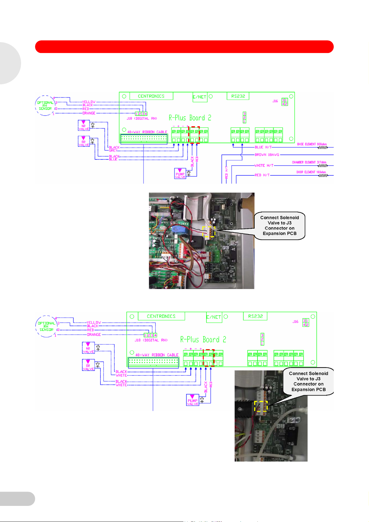
10. Replacement Expansion PCB fitting:
170 R - Refitting is a reversal of removal. Follow the wiring diagram and image below.
Galaxy 170 R / 48 R 120 V / 230 V CO
48 R - Refitting is a reversal of removal. Follow the wiring diagram and image below.
10
Page 11

Galaxy® CO2 Sensor Setup — Instructions
11. 170 R CO2 Sensor fitting
Unpack the new CO2 Sensor and fix in place with the bracket supplied and the original nuts
and washers and new spring washers but only reuse one of the original nylon washers in the
location shown in the image below. Fit the spring washers Tighten the M3 fixing nuts to 0.4
Nm (Newton meters).
1
Galaxy 170 R / 48 R 120 V / 230 V CO
2
Incubators
12. Route the Auto-Zero inlet tubing from the CO
back cover to the Solenoid Valve then connect the tubing to the top barb of the Solenoid Valve
as shown on top image page 12.
Sensor down between the insulation and the
2
11
Page 12

1
Incubators
2
Galaxy® CO2 Sensor Setup — Instructions
13. Route the tube from the Auto-Zero Pump “Out” (see Pump diagram at the bottom of Page 7)
to the bottom barb of the Solenoid Valve shown in the image above.
NOTE: Air flow must follow the direction of flow arrows on Auto-Zero Pump and CO
Valve.
Air Flow: Hepa filter..Air In….Auto-Zero pump..Air In / Air Out…….CO
In / Air Out…..CO2 Sensor Assembly…Air In.
Solenoid
2
Solenoid Valve…..Air
2
NOTE: If the elbow becomes loose when fitting tube, it must be resealed with elbow secured
Galaxy 170 R / 48 R 120 V / 230 V CO
in direction shown. If the elbow becomes loose, the integrity of the CO
compromised.
14. Cut the old Pump tubing in line with the glass fiber insulation and trim the CO
harness in line with the glass fibre insulation and strip and twist 7 mm from the end.
15. Connect the existing wiring harness to the CO
and right-hand image, page 13). Ensure you have stripped 7 mm of insulation from the
existing harness wires and twisted the strands before connecting them.
NOTE: Green on the existing harness connects to Brown on the new CO2 Sensor assembly
harness.
upgrade may be
2
Sensor wiring
2
Sensor connecting block (as shown on top left
2
12
Page 13

Galaxy® CO2 Sensor Setup — Instructions
1
Galaxy 170 R / 48 R 120 V / 230 V CO
2
Incubators
16. 48 R CO2 Sensor fitting:
NOTE for 48 R: The replacement CO
this tubing with spring and use the existing tubing already fitted to the Incubator. Unpack the
new CO
and new spring washers but only reuse one of the original nylon washers in the location
shown in the image below. Refit the spring over the existing tubing. Fit the spring washers
Tighten the M3 fixing nuts to 0.4 Nm (Newton Meters).
Sensor and fix in place with the bracket supplied and the original nuts and washers
2
Sensor has tubing pre fitted for the 170 R. Remove
2
13
Page 14

1
Incubators
2
Galaxy® CO2 Sensor Setup — Instructions
17. Disconnect the tube from the Auto-Zero Pump “Out” (see Pump diagram at bottom of page 7)
and connect to the “Pump Out to CO
image below). Using the new tubing supplied, cut a length and connect to the “Pump In” barb
of the Solenoid Valve shown in the image below.
Sensor” barb of the Solenoid Valve (as shown in the
2
NOTE: If the elbow becomes loose when fitting tube, it must be resealed and secured. If the
elbow becomes loose, the integrity of the CO2 upgrade may be compromised.
Galaxy 170 R / 48 R 120 V / 230 V CO
Note: Air flow must follow the direction of flow arrows on Auto-Zero Pump and CO
Valve.
Air Flow: Hepa filter..Air In….Auto-Zero pump..Air In / Air Out…….CO
In / Air Out…..CO
18. Connect the existing wiring harness to the CO
and right-hand image, page 15). Ensure you have stripped 7 mm of insulation from the
existing harness wires and twisted the strands before connecting them.
NOTE: Green on the existing harness connects to Brown on the new CO2 Sensor assembly
harness.
Sensor Assembly…Air In.
2
Solenoid
2
Solenoid Valve…..Air
2
Sensor connecting block (as shown on top left
2
14
Page 15

Galaxy® CO2 Sensor Setup — Instructions
1
Galaxy 170 R / 48 R 120 V / 230 V CO
2
Incubators
19. Refit the insulation block and trim a small pocket in the insulation to locate the connecting
block (as shown in yellow dashed box in image below).
20. Refit the rear access panel using the 8 x Pozidriv head screws with washers and refit the
Access Port Plug for the 170 R and the 4 x Pozidriv head screws with washers on the 48 R
(see drawings on Page 4).
21. Fit the new porous cover supplied to the CO
body until it touches the back wall of the chamber.
NOTE: It may be difficult to push on so use the palm of the hand to push back.
Sensor by sliding it over the brass measuring
2
15
Page 16

1
Incubators
2
Galaxy® CO2 Sensor Setup — Instructions
22. EPROM Replacement
NOTE: To avoid static damage, take anti-static precautions and avoid touching the legs of the
new device during fitting.
We recommended that an extractor tool is used to remove the existing EPROM. If an
extractor is not available then insert a small flat bladed screwdriver under one end of the IC
and gently ease it upwards, then insert the screwdriver under the other end and ease that end
up, repeat until the IC is free of the socket.
Before insertion of the replacement EPROM make sure you observe the proper orientation of
the device. Orientation is achieved by ensuring the notch is aligned with the notch in the IC
Socket of each device (see Notch circled in image below).
When fitting the EPROM in the socket ensure all legs are correctly aligned and none are bent
when inserted.
Galaxy 170 R / 48 R 120 V / 230 V CO
23. Equipment Tray (170 R) and Top Cover (48 R) refitting
170 R – Close the rear equipment tray and refit the 2 x large Pozidriv head screws.
48 R – Carefully refit the Top Cover using the 4 x large Pozidriv head screws taking care not
to trap any wires or tubing between the Top Cover and Equipment Tray.
1.3 To complete the installation the new CO2 Factors must be entered as follows
1. Power up the Incubator and program the CO2 level to 0.0%.
2. Enter the Engineering menu by pressing ‘DIAG’ then ‘ENG’ then enter the access code of
‘1973’ and press ‘ENTER’.
3. Select and enter the ‘CO2 Auto-Zero’ screen and adjust the Factor to the Zero Factor
provided by using the ¶ and · arrow keys and pressing ENTER.
4. Enter the ‘CO2 AUTOGAIN’ screen and select CO2 GAIN FACTOR by using the » key, enter
the Gain Factor provided by using the ¶ and · arrow keys and pressing ENTER. ‘EXIT’ this
screen and ‘EXIT’ the Engineering Menu to return to the front screen.
5. Humidify incubator.
6. Allow chamber environment to homogenize at 37 deg C set point. Typically 8 hours.
7. Program CO
8. Allow CO
9. Perform Auto-Zero cycle.
10. Perform calibration procedure.
to stabilize.
2
at 5 %.
2
16
Page 17

Galaxy® CO2 Sensor Setup — Instructions
2 Galaxy 170 S 230 V / 120 V CO2 Incubators
2 Galaxy 170 S 230 V / 120 V CO2 Incubators
2.1 K2 CO
Parts Supplied
1.3 m Tube, Silicone Rubber, Clear
20 Cable Tie, 2.5 x 100 Long
0.6 m Brown 18 AWG UL1015 105 DegC with Female Crimp Spade Terminal
Sensor update kit retro fit instructions
2
1CO
1 Porous Sensor Cover, Sintered
1 Bracket Strain Relief
6 Washer, M3 Spring, A2 Stainless Steel
3 M3 Washer
3M3 Nut
3 M3 detector spacer 3.18 mm ID x 7 mm
2 Cable Tie, 2.5 x 100 Long
1Nut M4
1 Spacer 9.53 x 12.7 Long
1 Cable Tie Mount
1 M4 x 20 Pozidriv Screw
1 Spring, Tube Support
1 Solenoid Valve 230 VAC or 120 VAC Assembly
1 Equipment Tray Cover Panel
2 M4 Washers
2 M4 x 6 Pozidriv Screws
1 PCB Assembly with bracket plate
3 M3 Washers
3 M3 x 12 Cheese Head, Stainless
3 Detector spacer, 3.18 mm ID x 7
1 5 V Miniature Diaphragm Pump
4 M3 x 6 Pozidriv Screw
6 Large Cable Tie, 3.5 mm . 300 mm long
6 Large Cable Tie Base, 27 mm x 27 mm
Sensor with Flying Leads and Connector Block
2
2
Galaxy 170 S 230 V / 120 V CO
2
Incubators
17
Page 18

2
Incubators
2
Galaxy® CO2 Sensor Setup — Instructions
Tools required/recommended
Large sized Pozidriv screwdriver – for Equipment Tray and cover screws
®
Small flat bladed screwdriver – for removing and fitting wires to WAGO
Side-Cutters – for cutting cable zip ties
5.5 mm nutspinner – for CO
Torque Limiting Screwdriver with attachment to fit M3 5.5 m Hex – for fitting M3 Hex fixing nuts on new CO
ESD Wrist strap
Sensor M3 fixing nuts
2
2.2 Removing existing parts
1. Power down the Incubator and completely disconnect from the Mains/Power Supply. Open
the outer and Inner Door then remove the white porous cover on the CO2 Sensor from inside
the chamber of the incubator (dashed red circle in image below).
block
Sensor
2
2. Remove the rear access panel by unplugging the access port plug and then unscrewing the 8
Galaxy 170 S 230 V / 120 V CO
x Pozidriv head screws with washers (see all screws and plug in dashed red circles in image
below).
NOTE: Protect top face of equipment tray with tape.
3. With the access panel removed, locate the insulation block covering the CO2 Sensor and
carefully remove the block (shown in yellow dashed box on top image of page 19) and place
to one side for refitting later. The rear of the CO
Sensor will now be visible.
2
18
Page 19

Galaxy® CO2 Sensor Setup — Instructions
4. Remove the existing CO2 Sensor by disconnecting the 5 way Molex connector and then
unplug the Auto-Zero port tubing leading from the pump (see dashed yellow circles on image
to the left below). Unscrew the 3 x M3 securing nuts and place to the side for refitting (only
one nylon washer will be reused).
2
Galaxy 170 S 230 V / 120 V CO
5. Open the rear equipment tray by unscrewing the 2 x large Pozidriv head screws and then
remove the cover plate shown arrowed in image on page 20 by unscrewing the 4 x Pozidriv
head screws. Discard the old plate after removal.
2
Incubators
19
Page 20

2
Incubators
2
Galaxy® CO2 Sensor Setup — Instructions
6. Locate the Auto-Zero Pump and disconnect the tubing leading to the CO
Auto-Zero Pump (see “Pump Out” in diagram below). The tubing is fixed to the pump barbs
using cable zip ties. Trace the tubing back to where it enters the Cover Plate access hole area
and cut the tubing back to this point using the side cutters; a new length of tubing will be fitted
later. Also disconnect the other tube into the Pump from the Air Zero Inlet Filter.
Galaxy 170 S 230 V / 120 V CO
7. Trace the Pump wiring back to the WAGO connector block (as shown on top image, page 21)
and use side cutters to carefully cut all cable zip ties which are securing the wiring as you go.
NOTE: It is very easy to damage wires when cutting cable zip ties so take care when doing
this. Use a small flat bladed screwdriver to release the Red and Black wiring from the WAGO
connecting block and withdraw the existing pump from its holder (see locations for Red and
Black wiring, reference top image, page 21).
Sensor from the
2
20
Page 21

Galaxy® CO2 Sensor Setup — Instructions
WAGO connecting block with Auto-Zero Pump connections highlighted
Fitting the new Parts
8. Fit the new Pump with Diode supplied in the Kit and cable zip tie the wiring down in the same
locations as the old pump. Trim the wires to length then strip and twist 7 mm for connecting
back into the WAGO connector block.
2
Galaxy 170 S 230 V / 120 V CO
2
Incubators
9. The PCB can now be positioned in the right-hand corner of the tray but it may be necessary
to relocate the 3 x Connectors for the Door Harness to clear room for the Auto-Zero Solenoid
Valve PCB/bracket (see blue arrows in image on following page). The Harness connectors
are cable zip tied to adhesive bases which are fixed down to the tray, there may also be other
cable zip ties and bases securing the wiring to the tray (see locations in dashed yellow circles
in image on following page.)
10. Cut all cable zip ties and relocate the connectors with the cable zip ties and bases provided in
the kit, leaving enough clearance for the Solenoid Check Valve PCB/bracket. After the Door
Harness connections have been moved the bracket mounting points will be visible.
21
Page 22

2
Incubators
2
Galaxy® CO2 Sensor Setup — Instructions
Door Harness Connectors
Solenoid Pump Valve PCB bracket mounting points
Galaxy 170 S 230 V / 120 V CO
11. Mount the PCB/bracket in the tray as shown in the image below using the screws supplied to
secure in position then route the wiring along the back of the Equipment Tray.
22
Page 23

Galaxy® CO2 Sensor Setup — Instructions
12. Route the Red/Black wires from the PCB to the Auto-Zero Pump connections on the WAGO
connecting block. Use the small flat bladed screwdriver to insert the wires into the right-hand
side of the WAGO connector block making a piggyback connection where the existing Red/
Black wires are connected. Take care when inserting the wires that the existing wires still
have a good connection and most importantly ensure correct orientation of the wires.
13. Mount the Solenoid Valve to the new cover plate using the fixings supplied and fit the new
cover plate in the position shown in the image below using the 4 x Pozidriv head screws
which were kept aside earlier. The tubing will be connected when fitting the new CO
Sensor.
2
2
Galaxy 170 S 230 V / 120 V CO
2
Incubators
23
Page 24

2
Incubators
2
Galaxy® CO2 Sensor Setup — Instructions
14. Connect the Solenoid Valve Neutral (Black wire with Crimp Female Spade) to a spare
location on the Neutral (Black/Blue) location on the Mains Terminal Block.
15. Connect the Valve Live (thin Red wire) to the left location on the J3 connector on the PCB (as
shown in the image below). Push down on Orange tab to open these lever clamp connectors.
Connect the stripped end of the Live In (thick Brown wire) to the right side of the J3 connector
(as shown in the image below).
Galaxy 170 S 230 V / 120 V CO
16. Route the Live (thick Brown wire with Female Spade Crimp) along the rear of the tray and
then to a spare location on the Live (Brown/Red) part of the Mains Terminal Block (as shown
in top images on page 25).
24
Page 25

Galaxy® CO2 Sensor Setup — Instructions
17. Cable zip tie all wires in place to secure to tray.
2
Galaxy 170 S 230 V / 120 V CO
18. Unpack the new CO
and washers and new spring washers but only reuse one of the original nylon washers in the
location shown in the image below. Fit a spring washer then M3 Washer with M3 Nut to each
of the studs through the bracket, reuse the Nylon washer with M3 Washer and Nut on the
other stud. Tighten the M3 fixing nuts to the recommended 0.4FT/LBS (Foot-Pounds).
Sensor and fix in place with the bracket supplied and the original nuts
2
2
Incubators
25
Page 26

2
Incubators
2
Galaxy® CO2 Sensor Setup — Instructions
19. Route the Auto-Zero inlet tubing from the CO2 Sensor (pre fitted to the new Sensor) down
between the insulation and the back cover to the Solenoid Valve and connect the tubing to the
top barb of the Solenoid Valve as shown in the image below.
Galaxy 170 S 230 V / 120 V CO
20. Route the tubing supplied from the new Auto-Zero Pump “Out” to the bottom barb of the
Solenoid Valve shown in the image above and reconnect the “Pump In – from Inlet filter”
tubing.to the other barb of the new Auto-Zero Pump.
NOTE: Air flow must follow the direction of flow arrows on Auto-Zero Pump and CO
Valve.
Air Flow: Hepa filter..Air In….Auto-Zero pump..Air In / Air Out…….CO
In / Air Out…..CO2 Sensor Assembly…Air In.
NOTE: If the elbow becomes loose when fitting tube, it must be resealed with elbow secured
in direction shown. If the elbow becomes loose, the integrity of the CO
compromised
Solenoid
2
Solenoid Valve…..Air
2
upgrade may be
2
26
Page 27

Galaxy® CO2 Sensor Setup — Instructions
21. Cut the old Pump tubing in line with the glass fibre insulation and also trim the CO2 Sensor
wiring harness to this point then strip and twist 7 mm from the end.
2
Galaxy 170 S 230 V / 120 V CO
22. Connect the existing wiring harness to the CO
right-hand images below). Ensure you have stripped 7 mm of insulation from the existing
harness wires and twisted the strands before connecting them.
NOTE: Green on the existing harness connects to Brown on the new CO2 Sensor assembly
harness.
Sensor connecting block (as shown in left and
2
2
Incubators
27
Page 28

2
Incubators
2
Galaxy® CO2 Sensor Setup — Instructions
23. Refit the insulation block and trim a small pocket in the insulation to locate the connecting
block (as shown in yellow dashed box in image below).
24. Refit the rear access panel using the 8 x Pozidriv head screws with washers and refit the
Access Port Plug.
25. Fit the new porous cover supplied to the CO
body until it touches the back wall of the chamber.
NOTE: It may be difficult to push on so use the palm of the hand to push back.
26. Close the rear equipment tray and refit the 2 x large Pozidriv head screws.
Sensor by sliding it over the brass measuring
2
Galaxy 170 S 230 V / 120 V CO
2.3 To complete the installation the new CO2 Factors must be entered as follows
1. Power up the Incubator and program the CO2 level to 0.0%.
2. Enter the ENGINEERING MENU by pressing the up º and down » arrow keys
simultaneously.
Hint!
To navigate the menu system use the arrow keys, press to select each screen and to exit
press .
3. Enter the CO2 rEF. screen in the Engineering Menu and enter the Factor provided by using
the º and » keys then press to store the change. Press to exit back to the Engineering
Menu.
4. Navigate up through the ENGINEERING Menu using the º key to the CO2 SP.N screen.
5. Enter the CO2 SP.N screen, then enter the Span Factor provided in exactly the same way as
entering the Ref Factor.
6. Exit the screen by pressing and exit the Engineering Menu by pressing to return to the
root screen.
7. Humidify incubator.
8. Allow chamber environment to homogenize at 37 deg C set point. Typically 8 hours.
9. Program CO
10. Allow CO
11. Perform Auto-Zero cycle.
12. Perform calibration procedure.
at 5 %.
2
to stabilize.
2
28
Page 29

Galaxy® CO2 Sensor Setup — Instructions
3 Galaxy 48 S / 14 S 120 V & 230 V CO2 Incubators
3 Galaxy 48 S / 14 S 120 V & 230 V CO2 Incubators
3.1 K5 CO
Parts Supplied
Sensor update kit retro fit instructions
2
1CO
1 Porous Sensor Cover, Sintered
1 Bracket Strain Relief
6 Washer, M3 Spring, A2 Stainless Steel
3 M3 Washer
6 Cable Tie, 2.5 x 100 Long
1M4 Nut
1 Cable Tie Mount
1 Spacer 9.53 x 12.7 long
1 M4 x 20 Pozidriv Screw
3M3 Nut
3 M3 detector spacer 3.18 mm ID x 7 mm
1 Black Cap
Sensor with Flying Leads and Connector Block
2
3
Galaxy 48 S / 14 S 120 V & 230 V CO
2
Incubators
Tools required/recommended
Large sized Pozidriv screwdriver – for Rear cover screws
5.5 mm nutspinner – for CO
Torque Limiting Screwdriver with attachment to fit M3 5.5 m Hex – for fitting M3 Hex fixing nuts on new CO
ESD Wrist strap
Sensor M3 Hex fixing nuts
2
3.2 Removing existing Parts
1. Power down the Incubator and completely disconnect from the Mains/Power Supply. Open
the outer Door (and Inner Door if fitted) then remove the white porous cover on the CO2
Sensor from inside the chamber of the incubator (dashed red circle in image below).
Sensor
2
29
Page 30

3
Incubators
2
Galaxy® CO2 Sensor Setup — Instructions
2. Rear cover removal:
48 S – Remove the CO
with washers (see all screws in dashed red circles in top left-hand image below).
14 S – Remove the rear access panel by unscrewing the 6 x Pozidriv head screws with
washers (see all screws in dashed red circles in top right-hand image below). The top two
screws secure the top cover.
Sensor access panel by unscrewing the 4 x Pozidriv head screws
2
3. With the access panel removed, locate the insulation block covering the CO
carefully remove the block (shown in yellow dashed boxes in images below) and place to one
side for refitting later. The rear of the CO
Galaxy 48 S / 14 S 120 V & 230 V CO
4. Remove the existing CO
unscrew the 3 x M3 securing nuts and place all the fixings to the side for refitting later (only
one nylon washer will be reused).
Sensor and
2
Sensor will now be visible.
2
Sensor by disconnecting the 5 way Molex connector and then
2
30
Page 31

Galaxy® CO2 Sensor Setup — Instructions
Fitting the new CO2 Sensor
5. 48 S CO
Unpack the new CO
NOTE: fix bracket with harness relief at bottom for the 48 S.
Fit a spring washer then M3 Washer with M3 Nut to each of the studs through the bracket,
reuse the Nylon washer with M3 Washer and Nut on the other stud. Tighten the M3 fixing nuts
to the recommended 0.4FT/LBS (Foot-Pounds).
14 S CO
Unpack the new CO
NOTE: fix bracket with the harness relief at the top for the 14 S.
Sensor fitting
2
2
Sensor fitting
2
2
Sensor and fix in place with the bracket supplied.
Sensor and fix in place with the bracket supplied.
3
Galaxy 48 S / 14 S 120 V & 230 V CO
Fit a spring washer then M3 Washer with M3 Nut to each of the studs through the bracket,
reuse the Nylon washer with M3 Washer and Nut on the other stud. Tighten the M3 fixing nuts
to the recommended 0.4FT/LBS (Foot-Pounds).
2
Incubators
31
Page 32

3
Incubators
2
Galaxy® CO2 Sensor Setup — Instructions
NOTE: Large slotted screw replaced with brass straight barbed connector and sealing black
cap.
Photograph "A"
Photograph "B"
Galaxy 48 S / 14 S 120 V & 230 V CO
32
Page 33

Galaxy® CO2 Sensor Setup — Instructions
Galaxy 14 with O2 option
3
Galaxy 48 S / 14 S 120 V & 230 V CO
A Illustrates O
inlet connector assembly
2
NOTE: O
obstruction.
6. Connect the existing wiring harness to the CO
and right-hand image, page 34). Ensure you have stripped 7 mm of insulation from the
existing harness wires and twisted the strands before connecting them.
NOTE: Green on the existing harness connects to Brown on the new CO2 Sensor assembly
harness.
inlet connector assembly is adjacent to sensor bracket, but does not cause an
2
Sensor connecting block (as shown on top left
2
2
Incubators
33
Page 34

3
Incubators
2
Galaxy® CO2 Sensor Setup — Instructions
7. Refit the insulation block and trim a small pocket in the insulation to locate the connecting
block (as shown in yellow dashed box in image below).
Galaxy 48 S / 14 S 120 V & 230 V CO
8. Refit the rear access panel using the 4 x Pozidriv head screws with washers on the 48 S and
6 x Pozidriv head screws with washers for the 14 S (see Fig. on p. 30).
9. Fit the new porous cover supplied to the CO2 Sensor by sliding it over the brass measuring
body until it touches the back wall of the chamber.
NOTE: It may be difficult to push on so use the palm of the hand to push back.
34
Page 35

Galaxy® CO2 Sensor Setup — Instructions
3.3 To complete the installation the new CO2 Factors must be entered as follows
1. Power up the Incubator and program the CO2 level to 0.0%.
2. Enter the ENGINEERING MENU by pressing the up º and down » arrow keys
simultaneously.
To navigate the menu system use the arrow keys, press ENTER to select each screen and to exit
Hint!
press .
3. Enter the CO2 rEF. screen in the Engineering Menu and enter the Factor provided by using
the º and » keys then press ENTER to store the change. Press to exit back to the
Engineering Menu.
4. Navigate up through the ENGINEERING Menu using the º key to the CO2 SP.N screen.
5. Enter the CO2 SP.N screen, then enter the Span Factor provided in exactly the same way as
entering the Ref Factor. Exit this screen by pressing and exit the Engineering Menu by
pressing to return to the root screen.
6. Humidify incubator.
7. Allow chamber environment to homogenize at 37 deg C set point. Typically 8 hours.
8. Program CO
9. Allow CO
10. Perform Auto-Zero cycle.
11. Perform calibration procedure.
at 5 %.
2
to stabilize.
2
3
Galaxy 48 S / 14 S 120 V & 230 V CO
2
Incubators
35
Page 36

Galaxy® CO2 Sensor Setup — Instructions
36
Page 37

Page 38

Your local distributor for New Brunswick products: www.nbsc.com/ContactUs
Eppendorf AG · 22331 Hamburg · Germany · Tel: +49 40 538 01-0 · Fax: +49 40 538 01-556 · E-mail: eppendorf@eppendorf.com
New Brunswick Scientific Europe B.V. · Nijmegen · The Netherlands · Tel: +31 (0) 24 3717 600 · Email: europe@nbsbv.nl
Eppendorf North America, Inc. · Hauppauge, N.Y. USA · Tel: +1 516 334 7500 · +1 800 645 3050 · E-mail: info@eppendorf.com
Application Support Europe, International: Tel: +49 1803 666 789 · E-mail: support@eppendorf.com
North America: Tel: +1 800 645 3050 menu option 2 · E-mail: techserv@eppendorf.com
Asia Pacific: Tel: +603 8023 6869 · E-mail: support_asiapacific@eppendorf.com
New Brunswick Scientific · 175 Freshwater Blvd., Enfield, CT 06082-4444 · USA
 Loading...