

Page 1
nualR/170 S CO2 Incubators
EN) manual
New Brunswick™
Galaxy
Operating manual
®
170 R/170 S CO2 Incubators
Page 2

Copyright
Copyright © 2014 Eppendorf AG, Germany. No part of this publication may be reproduced without the
prior permission of the copyright owner.
The company reserves the right to change information in this document without notice. Updates to
information in this document reflect our commitment to continuing product development and
improvement.
Trademarks
®
Eppendorf
and the Eppendorf logo are registered trademarks of Eppendorf AG, Germany.
New Brunswick™ and the New Brunswick™ logo are trademarks of Eppendorf AG, Germany.
®
Galaxy
is a registered trademark of Eppendorf, Inc., USA.
Microsoft
®
and Excel® are either registered trademarks or trademarks of Microsoft Corporation in the
United States and/or other countries.
®
Trademarks are not marked in all cases with ™ or
in this manual.
Eppendorf has attempted to identify the ownership of all trademarks from public records. Any omissions or
errors are unintentional.
6710900.017-00/012014
Page 3

®
Galaxy
170 R/170 S CO2 Incubators
English (EN)
Table of contents
1 Operating instructions . . . . . . . . . . . . . . . . . . . . . . . . . . . . . . . . . . . . . . . . . . . . . . . . . . . . . . . . . . . . . . 7
1.1 Using this manual . . . . . . . . . . . . . . . . . . . . . . . . . . . . . . . . . . . . . . . . . . . . . . . . . . . . . . . . . . . . . 7
1.2 Danger symbols and danger levels . . . . . . . . . . . . . . . . . . . . . . . . . . . . . . . . . . . . . . . . . . . . . . . . 7
1.2.1 Hazard symbols . . . . . . . . . . . . . . . . . . . . . . . . . . . . . . . . . . . . . . . . . . . . . . . . . . . . . . . . 7
1.2.2 Degrees of danger . . . . . . . . . . . . . . . . . . . . . . . . . . . . . . . . . . . . . . . . . . . . . . . . . . . . . . 7
1.3 Symbols used . . . . . . . . . . . . . . . . . . . . . . . . . . . . . . . . . . . . . . . . . . . . . . . . . . . . . . . . . . . . . . . . 8
2 Product description . . . . . . . . . . . . . . . . . . . . . . . . . . . . . . . . . . . . . . . . . . . . . . . . . . . . . . . . . . . . . . . . 9
2.1 Main illustration . . . . . . . . . . . . . . . . . . . . . . . . . . . . . . . . . . . . . . . . . . . . . . . . . . . . . . . . . . . . . . 9
Table of contents
2.1.1 Galaxy 170 R/170 S CO
2.2 Delivery package. . . . . . . . . . . . . . . . . . . . . . . . . . . . . . . . . . . . . . . . . . . . . . . . . . . . . . . . . . . . . 12
2.2.1 Inspection of boxes . . . . . . . . . . . . . . . . . . . . . . . . . . . . . . . . . . . . . . . . . . . . . . . . . . . . 12
2.2.2 Packing list verification . . . . . . . . . . . . . . . . . . . . . . . . . . . . . . . . . . . . . . . . . . . . . . . . . 13
2.3 Features. . . . . . . . . . . . . . . . . . . . . . . . . . . . . . . . . . . . . . . . . . . . . . . . . . . . . . . . . . . . . . . . . . . . 13
2.3.1 Control system. . . . . . . . . . . . . . . . . . . . . . . . . . . . . . . . . . . . . . . . . . . . . . . . . . . . . . . . 13
2.3.2 Direct heating system . . . . . . . . . . . . . . . . . . . . . . . . . . . . . . . . . . . . . . . . . . . . . . . . . . 13
2.3.3 Infrared sensor . . . . . . . . . . . . . . . . . . . . . . . . . . . . . . . . . . . . . . . . . . . . . . . . . . . . . . . 13
2.3.4 Controlled humidity tray . . . . . . . . . . . . . . . . . . . . . . . . . . . . . . . . . . . . . . . . . . . . . . . . 13
2.3.5 Seamless chamber . . . . . . . . . . . . . . . . . . . . . . . . . . . . . . . . . . . . . . . . . . . . . . . . . . . . 14
2.3.6 Standard features . . . . . . . . . . . . . . . . . . . . . . . . . . . . . . . . . . . . . . . . . . . . . . . . . . . . . 14
2.3.7 Multiple options . . . . . . . . . . . . . . . . . . . . . . . . . . . . . . . . . . . . . . . . . . . . . . . . . . . . . . 14
2.3.8 Two-level alarm system. . . . . . . . . . . . . . . . . . . . . . . . . . . . . . . . . . . . . . . . . . . . . . . . . 14
2.4 Stacking devices . . . . . . . . . . . . . . . . . . . . . . . . . . . . . . . . . . . . . . . . . . . . . . . . . . . . . . . . . . . . . 14
2.5 Optional equipment. . . . . . . . . . . . . . . . . . . . . . . . . . . . . . . . . . . . . . . . . . . . . . . . . . . . . . . . . . . 15
Incubators . . . . . . . . . . . . . . . . . . . . . . . . . . . . . . . . . . . . . . . . 9
2
3
3 Safety. . . . . . . . . . . . . . . . . . . . . . . . . . . . . . . . . . . . . . . . . . . . . . . . . . . . . . . . . . . . . . . . . . . . . . . . . . . 17
3.1 Intended use . . . . . . . . . . . . . . . . . . . . . . . . . . . . . . . . . . . . . . . . . . . . . . . . . . . . . . . . . . . . . . . . 17
3.2 User profile . . . . . . . . . . . . . . . . . . . . . . . . . . . . . . . . . . . . . . . . . . . . . . . . . . . . . . . . . . . . . . . . . 17
3.3 Application limits . . . . . . . . . . . . . . . . . . . . . . . . . . . . . . . . . . . . . . . . . . . . . . . . . . . . . . . . . . . . 17
3.3.1 Description of ATEX Guideline (94/9EC) . . . . . . . . . . . . . . . . . . . . . . . . . . . . . . . . . . . 17
3.4 Information on product liability . . . . . . . . . . . . . . . . . . . . . . . . . . . . . . . . . . . . . . . . . . . . . . . . . 18
3.5 Warnings for intended use . . . . . . . . . . . . . . . . . . . . . . . . . . . . . . . . . . . . . . . . . . . . . . . . . . . . . 18
3.5.1 Personal injury and damage to device . . . . . . . . . . . . . . . . . . . . . . . . . . . . . . . . . . . . . 18
4 Installation . . . . . . . . . . . . . . . . . . . . . . . . . . . . . . . . . . . . . . . . . . . . . . . . . . . . . . . . . . . . . . . . . . . . . . 21
4.1 Utilities requirements . . . . . . . . . . . . . . . . . . . . . . . . . . . . . . . . . . . . . . . . . . . . . . . . . . . . . . . . . 21
4.2 Selecting the location . . . . . . . . . . . . . . . . . . . . . . . . . . . . . . . . . . . . . . . . . . . . . . . . . . . . . . . . . 21
4.3 Unpacking the incubator. . . . . . . . . . . . . . . . . . . . . . . . . . . . . . . . . . . . . . . . . . . . . . . . . . . . . . . 22
4.4 Initial setup . . . . . . . . . . . . . . . . . . . . . . . . . . . . . . . . . . . . . . . . . . . . . . . . . . . . . . . . . . . . . . . . . 22
4.5 Making connections . . . . . . . . . . . . . . . . . . . . . . . . . . . . . . . . . . . . . . . . . . . . . . . . . . . . . . . . . . 26
5 Operation. . . . . . . . . . . . . . . . . . . . . . . . . . . . . . . . . . . . . . . . . . . . . . . . . . . . . . . . . . . . . . . . . . . . . . . . 29
5.1 Preparing for operation. . . . . . . . . . . . . . . . . . . . . . . . . . . . . . . . . . . . . . . . . . . . . . . . . . . . . . . . 29
5.2 Using the humidity tray. . . . . . . . . . . . . . . . . . . . . . . . . . . . . . . . . . . . . . . . . . . . . . . . . . . . . . . . 30
5.3 Operation for optional features . . . . . . . . . . . . . . . . . . . . . . . . . . . . . . . . . . . . . . . . . . . . . . . . . . 30
6 Operating controls and function for Galaxy 170 R Incubator . . . . . . . . . . . . . . . . . . . . . . . . . . . . . . 31
6.1 170 R control panel . . . . . . . . . . . . . . . . . . . . . . . . . . . . . . . . . . . . . . . . . . . . . . . . . . . . . . . . . . . 31
Page 4

Table of contents
Galaxy
4
English (EN)
®
170 R/170 S CO2 Incubators
6.2 Programming . . . . . . . . . . . . . . . . . . . . . . . . . . . . . . . . . . . . . . . . . . . . . . . . . . . . . . . . . . . . . . . 32
6.2.1 Temperature and CO
level . . . . . . . . . . . . . . . . . . . . . . . . . . . . . . . . . . . . . . . . . . . . . . 32
2
6.2.2 User access code. . . . . . . . . . . . . . . . . . . . . . . . . . . . . . . . . . . . . . . . . . . . . . . . . . . . . . 32
6.2.3 Removing user access code . . . . . . . . . . . . . . . . . . . . . . . . . . . . . . . . . . . . . . . . . . . . . 32
6.3 Referencing the CO
sensor with Auto-Zero. . . . . . . . . . . . . . . . . . . . . . . . . . . . . . . . . . . . . . . . 33
2
6.4 USER settings . . . . . . . . . . . . . . . . . . . . . . . . . . . . . . . . . . . . . . . . . . . . . . . . . . . . . . . . . . . . . . . 33
6.4.1 SET DATE AND TIME . . . . . . . . . . . . . . . . . . . . . . . . . . . . . . . . . . . . . . . . . . . . . . . . . . 34
6.4.2 AUDIBLE ALARM VOLUME ADJUST . . . . . . . . . . . . . . . . . . . . . . . . . . . . . . . . . . . . . . 34
6.4.3 PROGRAMMABLE CO
AUTOZERO. . . . . . . . . . . . . . . . . . . . . . . . . . . . . . . . . . . . . . . 34
2
6.4.4 DATALOGGER . . . . . . . . . . . . . . . . . . . . . . . . . . . . . . . . . . . . . . . . . . . . . . . . . . . . . . . . 35
6.4.5 POWER FREQUENCY . . . . . . . . . . . . . . . . . . . . . . . . . . . . . . . . . . . . . . . . . . . . . . . . . . 35
6.4.6 DISABLE . . . . . . . . . . . . . . . . . . . . . . . . . . . . . . . . . . . . . . . . . . . . . . . . . . . . . . . . . . . . 35
6.4.7 DISINFECTION (optional) . . . . . . . . . . . . . . . . . . . . . . . . . . . . . . . . . . . . . . . . . . . . . . . 35
6.5 DATALOGGER screen . . . . . . . . . . . . . . . . . . . . . . . . . . . . . . . . . . . . . . . . . . . . . . . . . . . . . . . . . 36
6.5.1 ALARM EVENTS . . . . . . . . . . . . . . . . . . . . . . . . . . . . . . . . . . . . . . . . . . . . . . . . . . . . . . 36
6.5.2 TEMPERATURE GRAPH + DOOR OPEN BAR CHART . . . . . . . . . . . . . . . . . . . . . . . . . 37
6.5.3 CO
GRAPH + DOOR OPEN BAR CHART . . . . . . . . . . . . . . . . . . . . . . . . . . . . . . . . . . . 38
2
6.5.4 DIAGNOSTIC CHAMBER ELEMENT GRAPH . . . . . . . . . . . . . . . . . . . . . . . . . . . . . . . . 38
6.5.5 DIAGNOSTIC DOOR GRAPH. . . . . . . . . . . . . . . . . . . . . . . . . . . . . . . . . . . . . . . . . . . . . 39
6.5.6 DIAGNOSTIC DOOR ELEMENT GRAPH. . . . . . . . . . . . . . . . . . . . . . . . . . . . . . . . . . . . 39
6.5.7 RESTART GRAPHIC RECORD. . . . . . . . . . . . . . . . . . . . . . . . . . . . . . . . . . . . . . . . . . . . 39
6.6 CHAMBER ALARMS menu screen . . . . . . . . . . . . . . . . . . . . . . . . . . . . . . . . . . . . . . . . . . . . . . . 39
6.6.1 Chamber alarm system function . . . . . . . . . . . . . . . . . . . . . . . . . . . . . . . . . . . . . . . . . . 40
6.7 DIAGNOSTICS menu screen. . . . . . . . . . . . . . . . . . . . . . . . . . . . . . . . . . . . . . . . . . . . . . . . . . . . 41
6.8 HELP MENU screen . . . . . . . . . . . . . . . . . . . . . . . . . . . . . . . . . . . . . . . . . . . . . . . . . . . . . . . . . . 42
7 Operating controls and function for Galaxy 170 S Incubator . . . . . . . . . . . . . . . . . . . . . . . . . . . . . . 43
7.1 170 S control panel . . . . . . . . . . . . . . . . . . . . . . . . . . . . . . . . . . . . . . . . . . . . . . . . . . . . . . . . . . . 43
7.2 Setting temperature and CO
. . . . . . . . . . . . . . . . . . . . . . . . . . . . . . . . . . . . . . . . . . . . . . . . . . . 44
2
7.3 Programming the alarm system . . . . . . . . . . . . . . . . . . . . . . . . . . . . . . . . . . . . . . . . . . . . . . . . . 44
7.3.1 Setting the high and low temperature alarms. . . . . . . . . . . . . . . . . . . . . . . . . . . . . . . . 44
7.3.2 Setting the CO
high and low alarms . . . . . . . . . . . . . . . . . . . . . . . . . . . . . . . . . . . . . . 45
2
7.3.3 Door open alarm . . . . . . . . . . . . . . . . . . . . . . . . . . . . . . . . . . . . . . . . . . . . . . . . . . . . . . 45
7.3.4 Alarm duration . . . . . . . . . . . . . . . . . . . . . . . . . . . . . . . . . . . . . . . . . . . . . . . . . . . . . . . 45
7.3.5 Alarm arming delay . . . . . . . . . . . . . . . . . . . . . . . . . . . . . . . . . . . . . . . . . . . . . . . . . . . . 46
7.4 Chamber alarm system . . . . . . . . . . . . . . . . . . . . . . . . . . . . . . . . . . . . . . . . . . . . . . . . . . . . . . . . 46
7.4.1 Temperature sensor system alarms . . . . . . . . . . . . . . . . . . . . . . . . . . . . . . . . . . . . . . . 47
7.4.2 Over-temperature cut-out and alarm . . . . . . . . . . . . . . . . . . . . . . . . . . . . . . . . . . . . . . 47
7.5 CO
Auto-zero system . . . . . . . . . . . . . . . . . . . . . . . . . . . . . . . . . . . . . . . . . . . . . . . . . . . . . . . . . 47
2
7.5.1 Auto-zero . . . . . . . . . . . . . . . . . . . . . . . . . . . . . . . . . . . . . . . . . . . . . . . . . . . . . . . . . . . . 47
7.5.2 Changing auto-zero frequency . . . . . . . . . . . . . . . . . . . . . . . . . . . . . . . . . . . . . . . . . . . 48
7.5.3 High temperature disinfection operation . . . . . . . . . . . . . . . . . . . . . . . . . . . . . . . . . . . 49
8 Maintenance . . . . . . . . . . . . . . . . . . . . . . . . . . . . . . . . . . . . . . . . . . . . . . . . . . . . . . . . . . . . . . . . . . . . . 51
8.1 Routine maintenance . . . . . . . . . . . . . . . . . . . . . . . . . . . . . . . . . . . . . . . . . . . . . . . . . . . . . . . . . 51
8.1.1 General . . . . . . . . . . . . . . . . . . . . . . . . . . . . . . . . . . . . . . . . . . . . . . . . . . . . . . . . . . . . . 51
8.1.2 Daily Checks . . . . . . . . . . . . . . . . . . . . . . . . . . . . . . . . . . . . . . . . . . . . . . . . . . . . . . . . . 51
8.1.3 Weekly checks . . . . . . . . . . . . . . . . . . . . . . . . . . . . . . . . . . . . . . . . . . . . . . . . . . . . . . . . 51
8.1.4 Monthly checks . . . . . . . . . . . . . . . . . . . . . . . . . . . . . . . . . . . . . . . . . . . . . . . . . . . . . . . 51
8.1.5 CO
Sampling with analyzer . . . . . . . . . . . . . . . . . . . . . . . . . . . . . . . . . . . . . . . . . . . . . 52
2
Page 5

®
Galaxy
170 R/170 S CO2 Incubators
English (EN)
8.1.6 Routine checks of the O2 control option (170 R only). . . . . . . . . . . . . . . . . . . . . . . . . . 52
8.2 Service. . . . . . . . . . . . . . . . . . . . . . . . . . . . . . . . . . . . . . . . . . . . . . . . . . . . . . . . . . . . . . . . . . . . . 53
8.2.1 Fuse replacement . . . . . . . . . . . . . . . . . . . . . . . . . . . . . . . . . . . . . . . . . . . . . . . . . . . . . 53
8.3 Cleaning . . . . . . . . . . . . . . . . . . . . . . . . . . . . . . . . . . . . . . . . . . . . . . . . . . . . . . . . . . . . . . . . . . . 53
8.4 Disinfection/Decontamination. . . . . . . . . . . . . . . . . . . . . . . . . . . . . . . . . . . . . . . . . . . . . . . . . . . 53
8.5 High temperature disinfection . . . . . . . . . . . . . . . . . . . . . . . . . . . . . . . . . . . . . . . . . . . . . . . . . . 55
9 Transport, storage and disposal . . . . . . . . . . . . . . . . . . . . . . . . . . . . . . . . . . . . . . . . . . . . . . . . . . . . . 57
9.1 Transport. . . . . . . . . . . . . . . . . . . . . . . . . . . . . . . . . . . . . . . . . . . . . . . . . . . . . . . . . . . . . . . . . . . 57
9.2 Storage . . . . . . . . . . . . . . . . . . . . . . . . . . . . . . . . . . . . . . . . . . . . . . . . . . . . . . . . . . . . . . . . . . . . 57
9.3 Disposal. . . . . . . . . . . . . . . . . . . . . . . . . . . . . . . . . . . . . . . . . . . . . . . . . . . . . . . . . . . . . . . . . . . . 57
10 Technical data. . . . . . . . . . . . . . . . . . . . . . . . . . . . . . . . . . . . . . . . . . . . . . . . . . . . . . . . . . . . . . . . . . . . 59
10.1 Weight/dimensions . . . . . . . . . . . . . . . . . . . . . . . . . . . . . . . . . . . . . . . . . . . . . . . . . . . . . . . . . . . 59
10.1.1 Equipment dimensions . . . . . . . . . . . . . . . . . . . . . . . . . . . . . . . . . . . . . . . . . . . . . . . . . 59
10.1.2 Internal dimensions. . . . . . . . . . . . . . . . . . . . . . . . . . . . . . . . . . . . . . . . . . . . . . . . . . . . 59
10.1.3 Transporting dimensions . . . . . . . . . . . . . . . . . . . . . . . . . . . . . . . . . . . . . . . . . . . . . . . 59
10.1.4 Shelves . . . . . . . . . . . . . . . . . . . . . . . . . . . . . . . . . . . . . . . . . . . . . . . . . . . . . . . . . . . . . 59
10.2 Power supply. . . . . . . . . . . . . . . . . . . . . . . . . . . . . . . . . . . . . . . . . . . . . . . . . . . . . . . . . . . . . . . . 60
10.2.1 Mains/electrical supply . . . . . . . . . . . . . . . . . . . . . . . . . . . . . . . . . . . . . . . . . . . . . . . . . 60
10.3 Fuses . . . . . . . . . . . . . . . . . . . . . . . . . . . . . . . . . . . . . . . . . . . . . . . . . . . . . . . . . . . . . . . . . . . . . . 60
10.4 Ambient conditions . . . . . . . . . . . . . . . . . . . . . . . . . . . . . . . . . . . . . . . . . . . . . . . . . . . . . . . . . . . 60
10.4.1 Temperature management . . . . . . . . . . . . . . . . . . . . . . . . . . . . . . . . . . . . . . . . . . . . . . 60
Table of contents
10.4.2 CO
control . . . . . . . . . . . . . . . . . . . . . . . . . . . . . . . . . . . . . . . . . . . . . . . . . . . . . . . . . . 61
2
10.4.3 Relative humidity . . . . . . . . . . . . . . . . . . . . . . . . . . . . . . . . . . . . . . . . . . . . . . . . . . . . . 61
10.4.4 Altitude limit . . . . . . . . . . . . . . . . . . . . . . . . . . . . . . . . . . . . . . . . . . . . . . . . . . . . . . . . . 61
10.4.5 Storage temperature . . . . . . . . . . . . . . . . . . . . . . . . . . . . . . . . . . . . . . . . . . . . . . . . . . . 61
10.4.6 Calibration . . . . . . . . . . . . . . . . . . . . . . . . . . . . . . . . . . . . . . . . . . . . . . . . . . . . . . . . . . . 61
5
11 Ordering information . . . . . . . . . . . . . . . . . . . . . . . . . . . . . . . . . . . . . . . . . . . . . . . . . . . . . . . . . . . . . . 63
11.1 Accessories . . . . . . . . . . . . . . . . . . . . . . . . . . . . . . . . . . . . . . . . . . . . . . . . . . . . . . . . . . . . . . . . . 63
11.2 Available options. . . . . . . . . . . . . . . . . . . . . . . . . . . . . . . . . . . . . . . . . . . . . . . . . . . . . . . . . . . . . 64
12 Equipment options . . . . . . . . . . . . . . . . . . . . . . . . . . . . . . . . . . . . . . . . . . . . . . . . . . . . . . . . . . . . . . . . 65
12.1 Cooling system . . . . . . . . . . . . . . . . . . . . . . . . . . . . . . . . . . . . . . . . . . . . . . . . . . . . . . . . . . . . . . 65
12.1.1 Troubleshooting the cooling system . . . . . . . . . . . . . . . . . . . . . . . . . . . . . . . . . . . . . . . 66
12.2 BMS relay contact alarm. . . . . . . . . . . . . . . . . . . . . . . . . . . . . . . . . . . . . . . . . . . . . . . . . . . . . . . 66
12.3 High temperature disinfection . . . . . . . . . . . . . . . . . . . . . . . . . . . . . . . . . . . . . . . . . . . . . . . . . . 68
12.3.1 Using the high temperature disinfection (Galaxy R). . . . . . . . . . . . . . . . . . . . . . . . . . . 68
12.3.2 Using the high temperature disinfection (Galaxy S) . . . . . . . . . . . . . . . . . . . . . . . . . . . 70
12.3.3 High temperature disinfection option with oxygen control . . . . . . . . . . . . . . . . . . . . . 71
12.4 O
control (1 - 19 %) (Galaxy R only). . . . . . . . . . . . . . . . . . . . . . . . . . . . . . . . . . . . . . . . . . . . . 72
2
12.4.1 Setting up the N
tank. . . . . . . . . . . . . . . . . . . . . . . . . . . . . . . . . . . . . . . . . . . . . . . . . . 72
2
12.4.2 Setting up oxygen control . . . . . . . . . . . . . . . . . . . . . . . . . . . . . . . . . . . . . . . . . . . . . . . 72
12.4.3 Operating guidelines . . . . . . . . . . . . . . . . . . . . . . . . . . . . . . . . . . . . . . . . . . . . . . . . . . . 74
12.4.4 Referencing to atmosphere . . . . . . . . . . . . . . . . . . . . . . . . . . . . . . . . . . . . . . . . . . . . . . 74
12.4.5 Replace sensor soon . . . . . . . . . . . . . . . . . . . . . . . . . . . . . . . . . . . . . . . . . . . . . . . . . . . 75
12.4.6 Replace sensor now . . . . . . . . . . . . . . . . . . . . . . . . . . . . . . . . . . . . . . . . . . . . . . . . . . . 75
12.4.7 Removing and replacing O
sensor. . . . . . . . . . . . . . . . . . . . . . . . . . . . . . . . . . . . . . . . 76
2
12.4.8 Replacing the filter disc . . . . . . . . . . . . . . . . . . . . . . . . . . . . . . . . . . . . . . . . . . . . . . . . 77
Page 6

Table of contents
Galaxy
6
English (EN)
®
170 R/170 S CO2 Incubators
12.4.9 Troubleshooting the O2 sensor . . . . . . . . . . . . . . . . . . . . . . . . . . . . . . . . . . . . . . . . . . . 78
12.4.10 Specifications . . . . . . . . . . . . . . . . . . . . . . . . . . . . . . . . . . . . . . . . . . . . . . . . . . . . . . . . 79
12.5 O
control (0.1 - 19 %) (Galaxy R only) . . . . . . . . . . . . . . . . . . . . . . . . . . . . . . . . . . . . . . . . . . . 80
2
12.5.1 Setting up the N
12.5.2 Setting up O
12.5.3 Enabling or disabling O
tank. . . . . . . . . . . . . . . . . . . . . . . . . . . . . . . . . . . . . . . . . . . . . . . . . . 80
2
control. . . . . . . . . . . . . . . . . . . . . . . . . . . . . . . . . . . . . . . . . . . . . . . . . . . 80
2
control. . . . . . . . . . . . . . . . . . . . . . . . . . . . . . . . . . . . . . . . . . 81
2
12.5.4 Alarms . . . . . . . . . . . . . . . . . . . . . . . . . . . . . . . . . . . . . . . . . . . . . . . . . . . . . . . . . . . . . . 81
12.5.5 Referencing to atmosphere . . . . . . . . . . . . . . . . . . . . . . . . . . . . . . . . . . . . . . . . . . . . . . 81
12.5.6 Programming desired O
level . . . . . . . . . . . . . . . . . . . . . . . . . . . . . . . . . . . . . . . . . . . 82
2
12.5.7 Precautions . . . . . . . . . . . . . . . . . . . . . . . . . . . . . . . . . . . . . . . . . . . . . . . . . . . . . . . . . . 82
12.6 O
control (1 - 95 %) (Galaxy R only). . . . . . . . . . . . . . . . . . . . . . . . . . . . . . . . . . . . . . . . . . . . . 83
2
12.6.1 Setting up the N
12.6.2 Setting up O
12.6.3 Enabling or disabling O
12.6.4 Important notes for O
tank. . . . . . . . . . . . . . . . . . . . . . . . . . . . . . . . . . . . . . . . . . . . . . . . . . 83
2
control. . . . . . . . . . . . . . . . . . . . . . . . . . . . . . . . . . . . . . . . . . . . . . . . . . . 84
2
control. . . . . . . . . . . . . . . . . . . . . . . . . . . . . . . . . . . . . . . . . . 84
2
levels > 80 % . . . . . . . . . . . . . . . . . . . . . . . . . . . . . . . . . . . . . . 85
2
12.6.5 Alarms . . . . . . . . . . . . . . . . . . . . . . . . . . . . . . . . . . . . . . . . . . . . . . . . . . . . . . . . . . . . . . 85
12.6.6 Referencing to atmosphere . . . . . . . . . . . . . . . . . . . . . . . . . . . . . . . . . . . . . . . . . . . . . . 85
12.6.7 Programming desired O
level . . . . . . . . . . . . . . . . . . . . . . . . . . . . . . . . . . . . . . . . . . . 86
2
12.6.8 Other precautions . . . . . . . . . . . . . . . . . . . . . . . . . . . . . . . . . . . . . . . . . . . . . . . . . . . . . 86
12.6.9 Specifications . . . . . . . . . . . . . . . . . . . . . . . . . . . . . . . . . . . . . . . . . . . . . . . . . . . . . . . . 86
12.7 O
Sensor replacement (Galaxy R only) . . . . . . . . . . . . . . . . . . . . . . . . . . . . . . . . . . . . . . . . . . . 86
2
12.8 IP66 sealed electrical outlet socket. . . . . . . . . . . . . . . . . . . . . . . . . . . . . . . . . . . . . . . . . . . . . . . 86
12.9 Humidity alert and monitoring package (Galaxy R only) . . . . . . . . . . . . . . . . . . . . . . . . . . . . . . 89
12.9.1 Humidity tray warning system . . . . . . . . . . . . . . . . . . . . . . . . . . . . . . . . . . . . . . . . . . . 89
12.9.2 Humidity display and alarm system . . . . . . . . . . . . . . . . . . . . . . . . . . . . . . . . . . . . . . . 90
12.10 Copper inner chamber . . . . . . . . . . . . . . . . . . . . . . . . . . . . . . . . . . . . . . . . . . . . . . . . . . . . . . . . 91
13 Stacking stand installation. . . . . . . . . . . . . . . . . . . . . . . . . . . . . . . . . . . . . . . . . . . . . . . . . . . . . . . . . . 93
13.1 Intended use . . . . . . . . . . . . . . . . . . . . . . . . . . . . . . . . . . . . . . . . . . . . . . . . . . . . . . . . . . . . . . . . 93
13.2 Warnings for intended use . . . . . . . . . . . . . . . . . . . . . . . . . . . . . . . . . . . . . . . . . . . . . . . . . . . . . 93
13.3 General description. . . . . . . . . . . . . . . . . . . . . . . . . . . . . . . . . . . . . . . . . . . . . . . . . . . . . . . . . . . 93
13.3.1 Ordering options . . . . . . . . . . . . . . . . . . . . . . . . . . . . . . . . . . . . . . . . . . . . . . . . . . . . . . 93
13.3.2 Stacking frame kit contents. . . . . . . . . . . . . . . . . . . . . . . . . . . . . . . . . . . . . . . . . . . . . . 94
13.4 Instructions for stacking incubators . . . . . . . . . . . . . . . . . . . . . . . . . . . . . . . . . . . . . . . . . . . . . . 94
13.5 Instructions for stacking a different model CO
incubator onto a Galaxy 170 . . . . . . . . . . . . . 102
2
14 Declaration of conformity . . . . . . . . . . . . . . . . . . . . . . . . . . . . . . . . . . . . . . . . . . . . . . . . . . . . . . . . . 105
14.1 Declaration of conformity for 170 R . . . . . . . . . . . . . . . . . . . . . . . . . . . . . . . . . . . . . . . . . . . . . 105
14.2 Declaration of conformity for 170 S . . . . . . . . . . . . . . . . . . . . . . . . . . . . . . . . . . . . . . . . . . . . . 106
Index . . . . . . . . . . . . . . . . . . . . . . . . . . . . . . . . . . . . . . . . . . . . . . . . . . . . . . . . . . . . . . . . . . . . . . . . . . 107
Page 7
Operating instructions
®
Galaxy
170 R/170 S CO2 Incubators
English (EN)
1 Operating instructions
1.1 Using this manual
Carefully read this operating manual before using the device for the first time.
Also observe the operating manual enclosed with the accessories.
The operating manual should be considered as part of the product and stored in a location that is easily
accessible.
When passing the device on to third parties, be sure to include this operating manual.
If this manual is lost, please request another one. The current version can be found on our website
www.eppendorf.com.
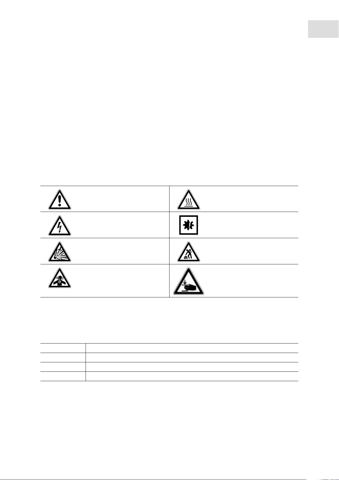
1.2 Danger symbols and danger levels
1.2.1 Hazard symbols
7
Hazard point Burns
Electric shock Material damage
Explosion Heavy loads
Inhalation Crush
1.2.2 Degrees of danger
The following degree levels are used in safety messages throughout this manual. Acquaint yourself with
each item and the potential risk if you disregard the safety message.
DANGER Will lead to severe injuries or death.
WARNING May lead to severe injuries or death.
CAUTION May lead to light to moderate injuries.
NOTICE May lead to material damage.
Page 8

Operating instructions
®
8
Galaxy
English (EN)
170 R/170 S CO2 Incubators
1.3 Symbols used
Example Meaning
You are requested to perform an action.
1.
2.
• List.
Perform these actions in the sequence described.
References useful information.
Page 9
2 Product description
2.1 Main illustration
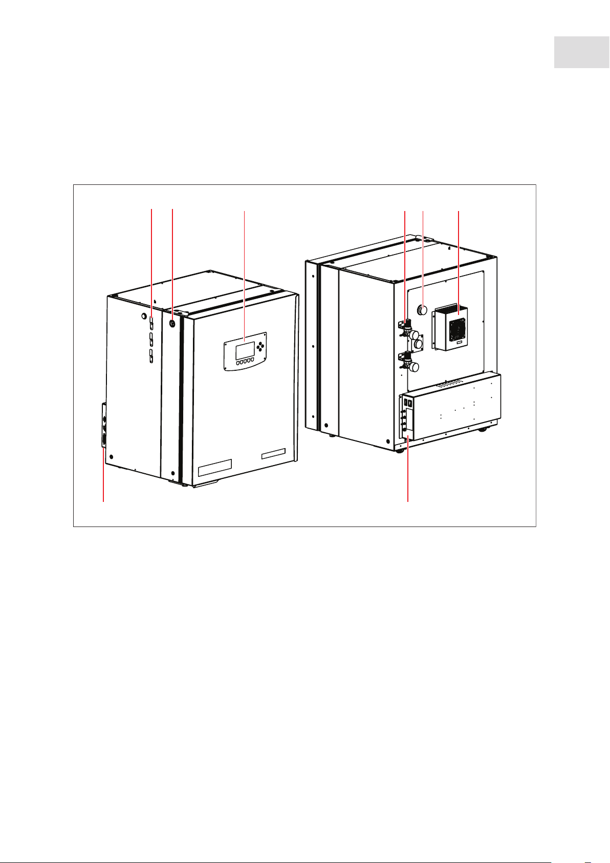
2.1.1 Galaxy 170 R/170 S CO2 Incubators
Abb. 2-1: Front and rear view of the 170 R/170 S CO2 Incubators
Galaxy
®
170 R/170 S CO2 Incubators
English (EN)
Product description
9
21
3 65
4
Fig. 2-1: Front and rear view of the 170 R/170 S CO2 Incubators
1 Sensor cover holder (present on older models)
2CO
sample port
2
3 Display/Interface (170 R display shown)
4 Inline regulator location (recommended)
5 Access port
6 Heat exchanger (cooling option only)
7 Left-hand side of control box
8 Right-hand side of control box
78
Page 10
10
Product description
®
Galaxy
170 R/170 S CO2 Incubators
English (EN)
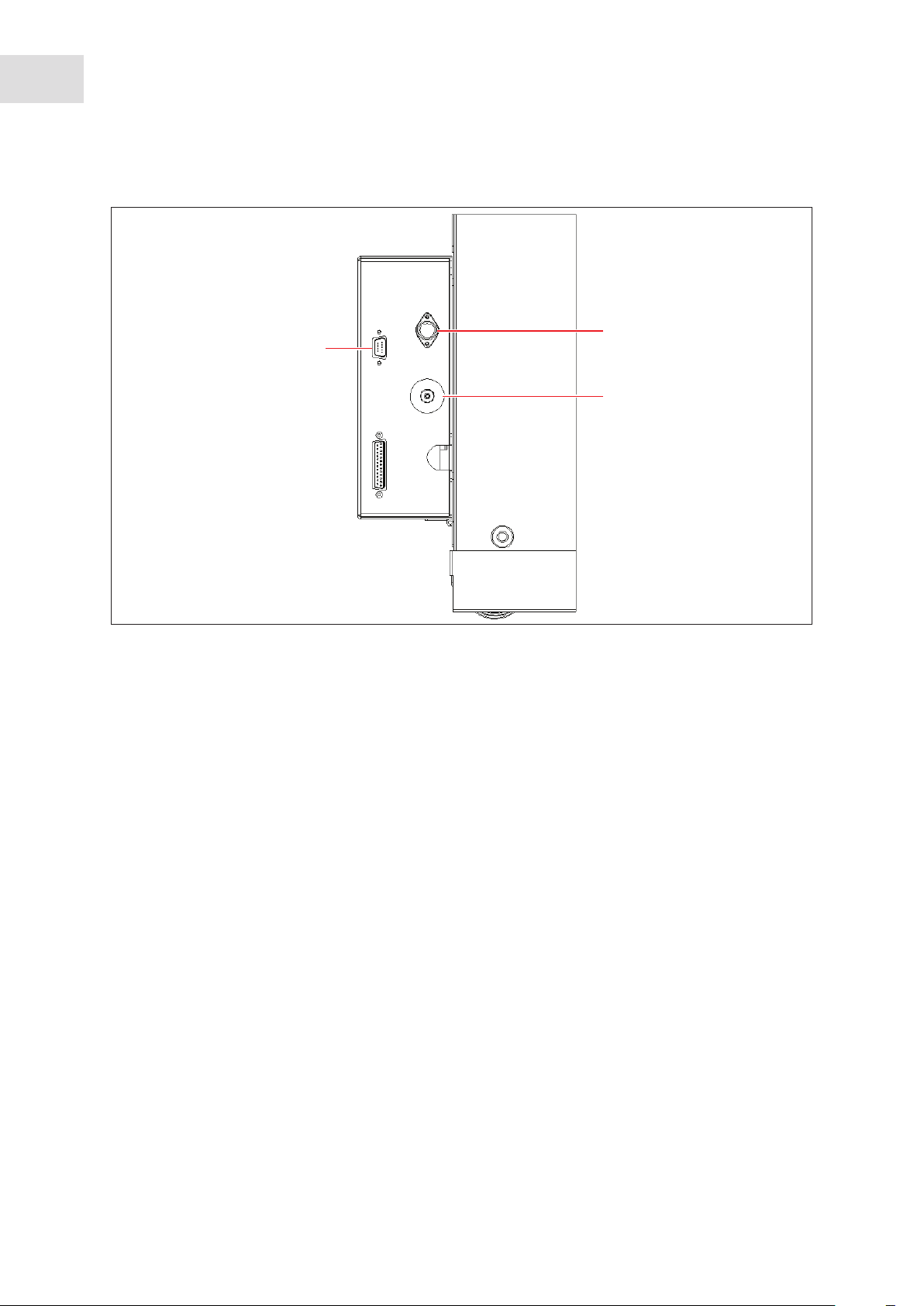
Abb. 2-2: Left-hand side control box
2
1
3
Fig. 2-2: Left-hand side control box
1 BMS relay contact alarm socket (Optional) 2 Auto-Zero filter
Page 11
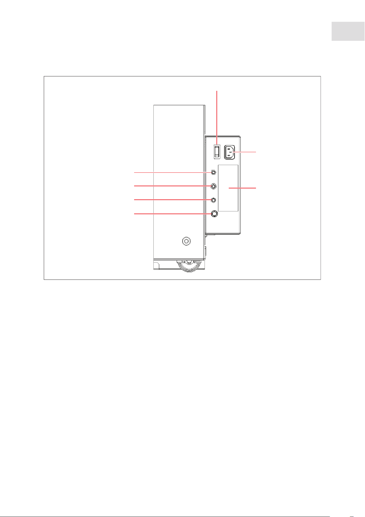
Abb. 2-3: Right-hand side control box
®
Galaxy
170 R/170 S CO2 Incubators
11
English (EN)
1
2
7
Product description
6
5
4
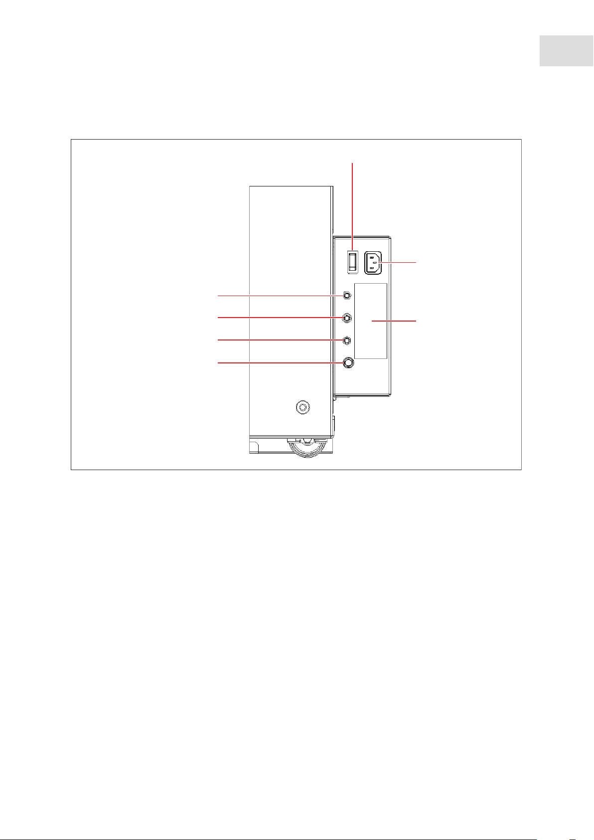
Fig. 2-3: Right-hand side control box
1 On/Off switch
2 Mains/power cord receptacle
3 Label
4 Fuse holder
3
inlet (170 R optional only, option not
5N
2
available on 170 S)
6CO
7O
inlet
2
inlet (170 R optional only, option not
2
available on 170 S)
Page 12

12
Product description
®
Galaxy
170 R/170 S CO2 Incubators
English (EN)
2.2 Delivery package
Quantity Description
1 Operating manual
4
2
1
1
2
1
1
1
4
2
1
3
3
2
Non-tip perforated shelves
Installed
Wired shelf racks
Installed
Humidity tray
Installed
White porous CO
Installed
Packed in accessories bag
Black sensor cover
Installed
Mains/power cord
Packed in box inside outer carton
6 mm (~1/4 in) bore PVC hose, with large white filter
Packed in accessories bag
Screw-in lifting handles
Packed in accessories bag
Tubing clips
Packed in accessories bag
Auto-zero CO
inlet filter
2
Installed
Spare shelf rack foot
Packed in accessories bag
Spare shelf rack spacer
Packed in accessories bag
Silicone rubber suction feet
Packed in accessories bag (4 for 170 S)
sensor cover
2
2.2.1 Inspection of boxes
Inspect the boxes carefully for any damage that may have occurred during shipping. Report any damage to
the carrier and to your local Eppendorf sales order department immediately.
Page 13

Product description
English (EN)
Galaxy
®
170 R/170 S CO2 Incubators
2.2.2 Packing list verification
Unpack your order, saving the packing materials for possible future use. Save the operating manual for
instruction and reference. Verify against your Eppendorf packing list that you have received the correct
materials, and that nothing is missing. If any part of your order was damaged during shipping, is missing,
or fails to operate, fill out the "Customer Feedback" form, available online at
newbrunswick.eppendorf.com/.
http://
2.3 Features
The Galaxy 170 R/170 S CO2 Incubator is microprocessor-controlled and designed to ensure accurate and
reliable operation.
2.3.1 Control system
13
The incubator incorporates a sophisticated control system that allows for easy programming, control and
monitoring of the chamber conditions.
2.3.2 Direct heating system
A direct heating system, utilizing a thermal heating element, completely surrounds the incubator, providing
an even temperature within the chamber. The independently and directly heated outer door is designed to
ensure an even distribution of heat. This system ensures a rapid, controlled return to optimum chamber
conditions after a door opening while also preventing any overshoot. The incubator’s direct heat system
provides for optimal use of laboratory space by allowing the most efficient internal volume for the footprint
of the instrument.
2.3.3 Infrared sensor
A solid-state infrared sensor is used to control the level of CO2, providing excellent reliability, while
remaining unaffected by humidity. The CO2 system has a programmable automatic zero system (Auto-zero)
to re-reference the sensor baseline to atmospheric CO
filtered atmospheric gas to the sensor. The chamber atmosphere within the sensor is completely displaced,
allowing the control system to automatically reference the sensor, after which the pump is switched off,
allowing the chamber atmosphere to homogenize back into the sensor. This provides for accurate CO
control without disturbing the chamber environment. For programming information (see Temperature and
CO
level on p. 32). For Auto-Zero instructions (see PROGRAMMABLE CO2 AUTOZERO on p. 34).
2
levels at regular intervals. A small pump supplies
2
2
2.3.4 Controlled humidity tray
A controlled water tray at the bottom of the incubator allows a high, uniform relative humidity (RH) while
preventing condensation in other parts of the chamber. Perforated shelves are provided as standard to
facilitate a much faster recovery of RH conditions in the chamber than with unperforated shelves.
Page 14

14
Product description
®
Galaxy
English (EN)
170 R/170 S CO2 Incubators
2.3.5 Seamless chamber
The 170-liter chamber is seamless, to provide a sanitary and easy-to-clean environment, and all internal
components are manufactured from polished stainless steel. The shelves (which are non-tip), shelf racks
and humidity tray are easily removed without tools for thorough cleaning and are capable of being
sterilized. Air circulation is achieved without the use of a fan, eliminating duct work (a potential source of
contamination), simplifying cleaning, eliminating vibration, and facilitating use of microplates and
low-volume culture.
2.3.6 Standard features
The Galaxy 170 R/170 S contain many standard features usually seen as options. It has a sealed inner glass
door with a cam action lock to allow viewing of the cultures without compromising the internal atmosphere.
This is also available as a split 4- or 8-inner-door option (to coordinate with shelves), which is ideal for
critical hypoxic studies. In addition, there is a 25 mm (1 in) access port now standard to allow for seamless
integration of independent probes or other equipment through the chamber.
2.3.7 Multiple options
The incubator features multiple options that can be installed to simplify maintenance and provide superior
control over experimental conditions. For example, high-temperature disinfection quickly and conveniently
disinfects the incubator’s chamber at 120 °C, without the need to remove interior components or the CO
sensor. A humidity alert and monitoring package display relative humidity levels in the chamber on the
display and warns the user before the humidity tray runs out of water, preventing dehydration of samples.
Oxygen control provides for conditions that require above- or below-ambient oxygen levels. These and
other options and accessories provide for a uniquely flexible CO
demanding requirements. For details on equipment options (see Equipment options on p. 65).
incubator capable of meeting the most
2
2
2.3.8 Two-level alarm system
The incubator incorporates a two-level alarm system. The system alarms occur only if a problem develops
with system components that require user intervention to rectify. The incubator also incorporates an
over-temperature safety system that operates independently from the main control system.
2.4 Stacking devices
The incubator is designed so that one incubator can be safely stacked on top of either another Galaxy 170 R
or a Galaxy 170 S using the optional stacking kit, which includes instructions. It is not possible to put any
other type of incubator or heavy apparatus on top, as the top cover and stacking kit are designed to support
only the feet of another Galaxy 170 incubator. For installation instructions (see Stacking stand installation on
p. 93).
Page 15

Product description
English (EN)
Galaxy
®
170 R/170 S CO2 Incubators
2.5 Optional equipment
The equipment options are factory-installed and model-dependent. A precise description of the equipment
options can be found in this manual (see Equipment options on p. 65).
15
Page 16

16
Product description
®
Galaxy
170 R/170 S CO2 Incubators
English (EN)
Page 17
Safety
English (EN)
Galaxy
®
170 R/170 S CO2 Incubators
3 Safety
3.1 Intended use
Eppendorf line of CO2 Incubators are microprocessor-controlled instruments designed for cell culture. The
direct-heated, fanless chambers are designed to provide high humidity levels, minimal vibration and
precisely-regulated atmosphere of temperature and gas(ses) required for cell growth in T-flasks,
microplates, and other cultureware. They are intended for indoor laboratory use, only.
CAUTION! Lack of safety due to incorrect accessories or spare parts
Accessories and spare parts that are not recommended by Eppendorf compromise the safety,
function and precision of the device. Eppendorf cannot be held liable or accept any liability for
damage resulting from the use of non-recommended accessories and spare parts.
Only use accessories and original spare parts recommended by Eppendorf.
17
3.2 User profile
The device may only be operated by trained lab personnel who have carefully read this operating manual
and are familiar with the device functions.
3.3 Application limits
3.3.1 Description of ATEX Guideline (94/9EC)
DANGER! Explosion hazard
Do not operate the device in areas where work is completed with explosive substances.
Do not use this device to process any explosive or highly reactive substances.
Do not use this device to process any substances which could create an explosive
atmosphere.
Due to its design and the ambient conditions in its interior, the device is not suitable for use in potentially
explosive atmospheres.
The device may only be used in a safe environment, e.g., the open atmosphere of a ventilated lab.
The use of substances which may contribute to a potentially explosive atmosphere is not permitted.
The final decision regarding the risks associated with using these types of substances is the user's
responsibility.
Page 18
18
Safety
®
Galaxy
English (EN)
170 R/170 S CO2 Incubators
3.4 Information on product liability
In the following cases, the designated protection of the device may be compromised.
The liability for the function of the device passes to the operator if:
• The device is not used in accordance with this operating manual.
• The device is used outside of the range of application described in the succeding chapters.
• The device is used with accessories or consumables that were not approved by Eppendorf.
• Service or maintenance is completed on the device by people who are not authorized by Eppendorf.
• The owner has made unauthorized modifications to the device.
3.5 Warnings for intended use
Before using the device, read the operating manual and observe the following general safety instructions.
3.5.1 Personal injury and damage to device
WARNING! Risk of personal injury
Elevated levels of CO
incubator.
Wear personal protective equipment (PPE).
WARNING! Risk of personal injury
Burns due to hot surface.
Do not touch the equipment during the high temperature disinfection cycle.
Do not open equipment door during the cycle.
CAUTION! Risk of personal injury
At least four people are required to safely lift the incubator.
NOTICE! Risk of material damage
Never try to lift the incubator by its door; this would cause permanent damage to the
incubator.
may be found in and around the operating area of the CO2
2
NOTICE! Risk of material damage
To avoid possible damage to the CO
the incubator is switched off, or when a high temperature disinfection cycle is initiated
(optional feature).
sensor, never leave water in the humidity tray while
2
Allow a clearance of 50 mm (2 in) to allow access for oxygen sensor (if installed) removal.
Page 19

NOTICE! Risk of material damage
Galaxy
®
170 R/170 S CO2 Incubators
English (EN)
Safety
19
CO
gas pressure must not exceed 5 PSI (0.35 bar).
2
NOTICE! Risk of material damage
Working with electrical power inside a humid environment (where the incubator is
humidified) can cause damage. The following precautions should be observed:
The instrument or equipment, and its external connections, to be used inside the chamber
should be specified as suitable for use in a humid environment, and at 37 °C (see also
“Using Powered Equipment within the Chamber”). If in doubt, consult with the
manufacturer of the equipment.
Always ensure the connections are properly and securely made.
Be sure to switch OFF the green illuminated switch on the front left of the incubator before
connecting or disconnecting equipment inside the chamber, if equipped with optional IP66
socket.
The Sealing Cap must always be in place when the socket is not in use.
Both the incubator and the IP66 enclosure must be plugged into an electrical supply
protected by an RCD device. Any device chosen must be a self-resetting type which will
automatically reconnect power to the incubator as soon as power is restored following a
power failure.
Page 20

20
Safety
®
Galaxy
170 R/170 S CO2 Incubators
English (EN)
Page 21
Installation
English (EN)
Galaxy
®
170 R/170 S CO2 Incubators
4 Installation
4.1 Utilities requirements
The following utilities requirements are needed for operation:
Utility Requirement
Electricity 120 V, 50/60 Hz earthed/grounded mains/electrical supply with minimum
capacity of 10 amps
230 V, 50/60 Hz earthed/grounded mains/electrical supply with minimum
capacity of 8 amps
CO2 gas Cylinder with 100 % CO2 vapor withdrawal, together with a two-stage
regulator for pressure control to 18.85 PSI (1.3 bar)
CO
gas pressure must not exceed 5 PSI (0.35 bar). It is recommended that a in-line pressure
2
regulator be used for each gas type introduced into the incubator to precisely control gas
pressure (see Accessories on p. 63).
21
4.2 Selecting the location
Select a level surface capable of withstanding the operating weight of the incubator. Actual operating
weight will be dependent on both the options installed, and the material stored in the incubator.
The incubator is designed to operate at a chamber temperature of 4.0 °C above ambient, and at an absolute
minimum ambient temperature of 15 °C if the incubator is being operated at 37 °C. Maximum allowable
ambient temperature is 28 °C.
Position incubator to allow clearance for opening door and access to the CO
located on the left side of the incubator.
Avoid placing the incubator in areas that may affect performance, such as those listed below.
DO NOT place the incubator:
• Directly under, beside or within the air flow of heating or air-conditioning ducts, or other drafts;
• Directly beside heat-generating equipment such as a heater, an autoclave or an oven;
• Near the exhaust of heat- or cold-generating equipment;
• Near a window exposed to direct sunlight;
• Directly on top of any heat-generating apparatus;
• Without minimum ventilation clearance of 10 mm (0.5 in) all around (50 mm (2 in) in back if you have
the cooling system option).
sample port
2
Page 22
22
Installation
®
Galaxy
170 R/170 S CO2 Incubators
English (EN)
4.3 Unpacking the incubator
CAUTION! Risk of personal injury
At least four people are required to safely lift the incubator.
NOTICE! Risk of material damage
Never try to lift the incubator by its door; this would cause permanent damage to the
incubator.
1. Install the four lifting handles into the tapped holes on both sides of the incubator.
Abb. 4-1: Installing lifting handles
1
Fig. 4-1: Installing lifting handles
1 Access port 2 Lifting handles
2. Carefully move the incubator to its operational location using lifting handles.
Silicone rubber suction feet are supplied for non-slip application.
3. Remove all internal packaging.
4. Remove the four lifting handles from the incubator and store for future use.
4.4 Initial setup
2
1. Place the silicone rubber suction feet onto the incubator’s adjustable feet.
Keep silicone rubber suction feet installed at all times.
2. Place two rubber shelf rack feet, and one shelf rack spacer onto each shelf rack (see Fig. 4-2 on p. 23).
3. Place the two shelf racks inside the chamber. Ensure that the cushioned tubing spacers are snug against
the side walls; these spacers allow clearance for the shelves.
Page 23
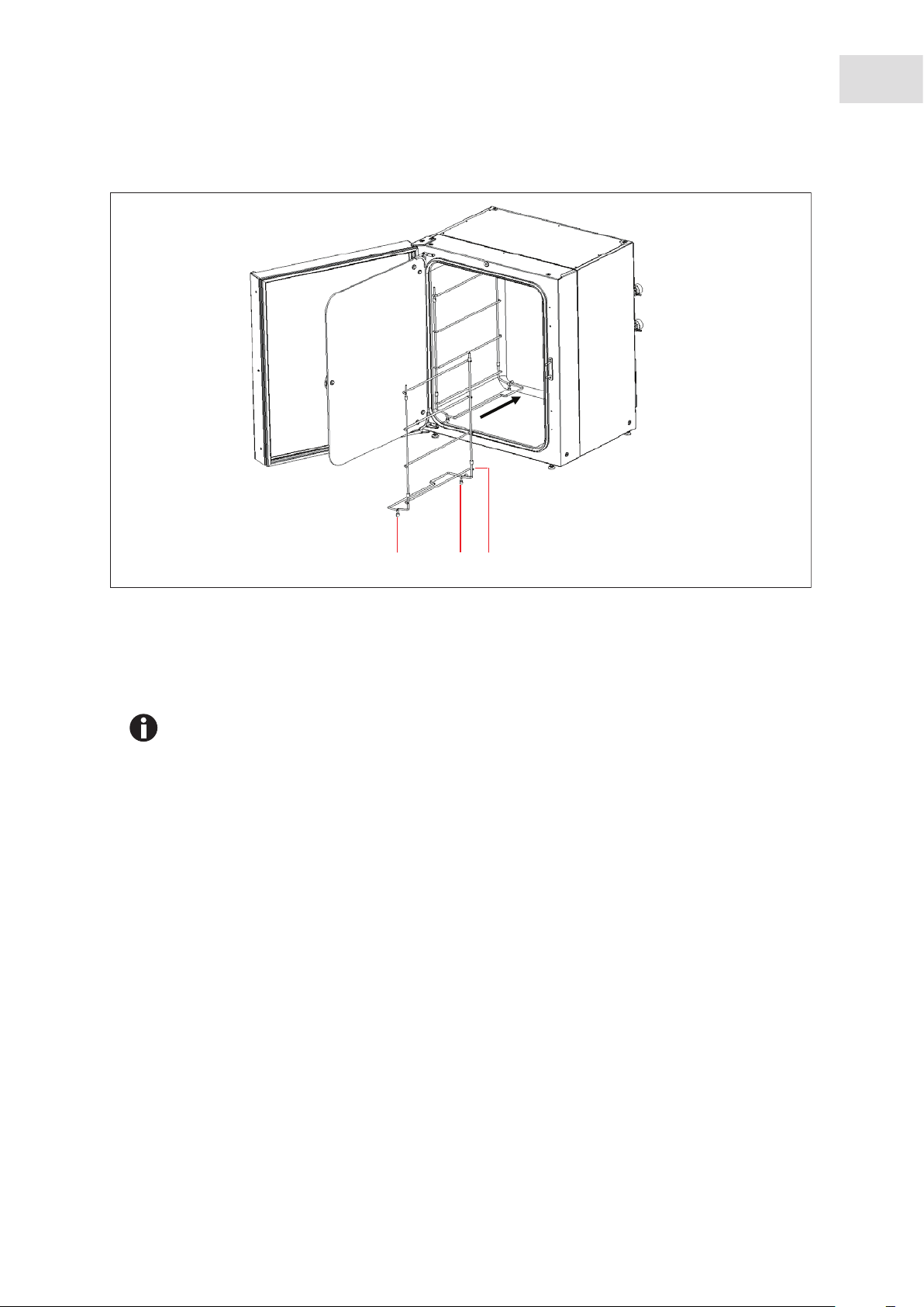
Abb. 4-2: Inserting shelf racks
Galaxy
®
170 R/170 S CO2 Incubators
English (EN)
Installation
23
112
Fig. 4-2: Inserting shelf racks
1 Shelf rack feet 2 Shelf rack spacer
Only shelf racks for four shelves are shown in this manual. Shelf racks for eight shelves are
also available.
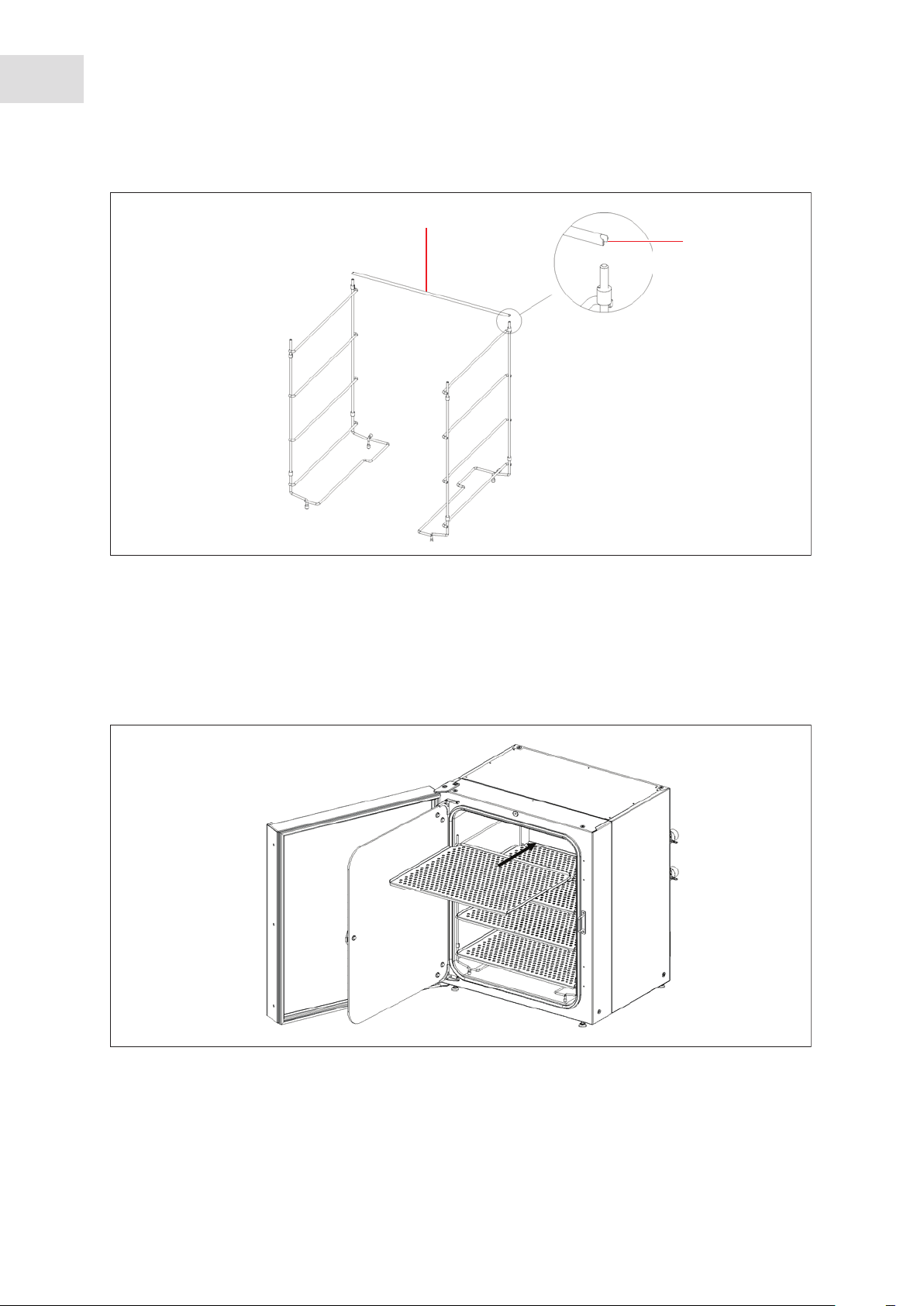
4. Install the tie rod at the back of the shelves to hold both sides together.
Page 24
24
Installation
®
Galaxy
170 R/170 S CO2 Incubators
English (EN)
Abb. 4-3: Installing tie bar to shelf racks
1
2
Fig. 4-3: Installing tie bar to shelf racks
1 Tie rod 2 Tie rod anti-tip groove
5. Install the shelves, top to bottom. Ensure that each shelf’s anti-tip groove is properly inserted (faced
upward and to the rear of the incubator) onto each of the shelf rack guides.
Abb. 4-4: Inserting shelves
Fig. 4-4: Inserting shelves
Page 25
®
Galaxy
170 R/170 S CO2 Incubators
English (EN)
6. Level the incubator by adjusting the feet. Place a small level on the second shelf of the incubator. Adjust
the leveling feet until the incubator is level and stable. Lock the leveling feet in place by tightening the
locking nuts on each foot.
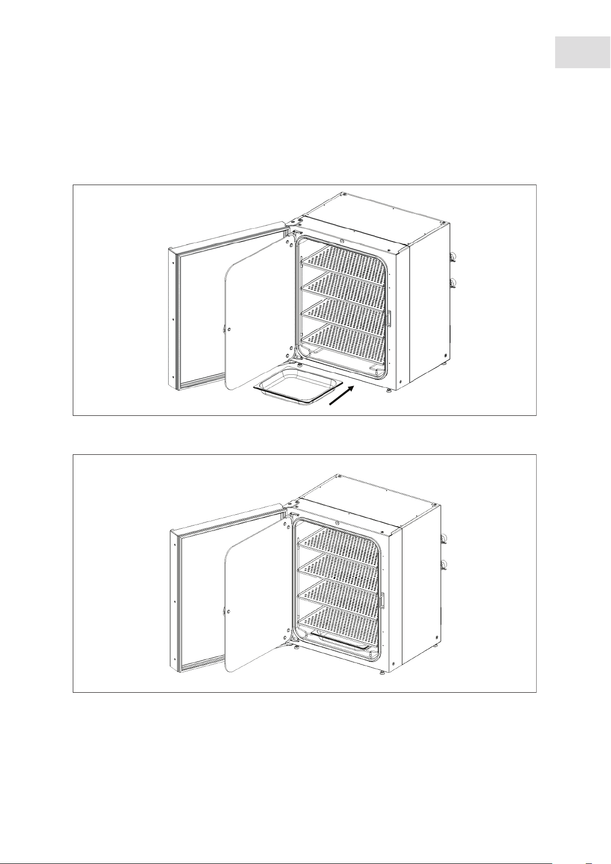
7. Slide the humidity tray onto the lowest shelf rack support.
Abb. 4-5: Installing the humidity tray
Installation
25
Fig. 4-5: Installing the humidity tray
Abb. 4-6: Humidity tray installed
Fig. 4-6: Humidity tray installed
Page 26
26
Installation
®
Galaxy
English (EN)
170 R/170 S CO2 Incubators
4.5 Making connections
WARNING! Risk of personal injury
Elevated levels of CO
incubator.
may be found in and around the operating area of the CO2
2
Wear personal protective equipment (PPE).
WARNING! Danger due to incorrect power supply
Only connect the device to voltage sources that meet the requirements on the name plate.
Only use sockets with a protective earth (PE) conductor and suitable power cable.
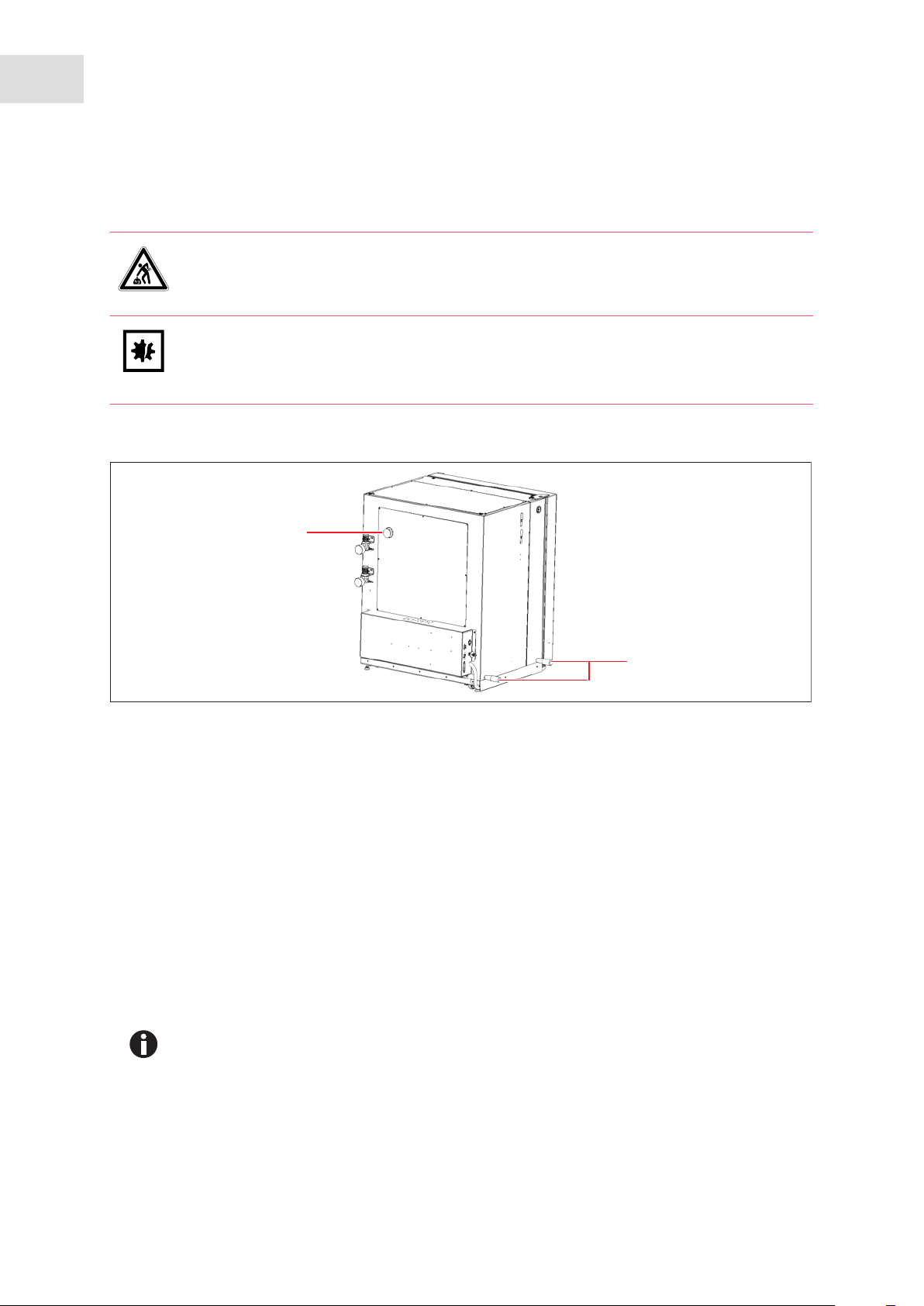
1. Remove sensor (CO2, O2, and RH) protective cover (option dependant), and store for future use.
2. Remove gas inlet connector protection cap.
Page 27
®
Galaxy
170 R/170 S CO2 Incubators
3. Attach supplied 6 mm bore PVC hose with large white filter to gas inlet connector.
Abb. 4-7: Making connections
1
2
7
Installation
27
English (EN)
Fig. 4-7: Making connections
1 On/Off switch
2 Mains/power cord receptacle
3 Label
4 Fuse holder
6
3
5
4
inlet (170 R optional only, option not
5N
2
available on 170 S)
6CO
7O
inlet
2
inlet (170 R optional only, option not
2
available on 170 S)
4. Attach recommended optional in-line pressure regulator (not supplied), if applicable. For connection
location (see Fig. 2-1 on p. 9).
Page 28

28
Installation
®
Galaxy
170 R/170 S CO2 Incubators
English (EN)
Attaching in-line pressure regulator, (not supplied), is a recommended option.
Abb. 4-8: In-line pressure regulator
Fig. 4-8: In-line pressure regulator
• The in-line pressure regulator controls Secondary Gas Pressure. A default pressure setting
of 5 PSI (0.35 bar) is recommended.
• A large size cylinder of “CO
- Vapour Withdrawal” is required to supply the incubator.
2
This cylinder controls Primary Gas Pressure. Fitting a Two-Stage CO
is recommended.
• Ensure the protective cover(s) are removed from all sensor(s) and replaced in the holder
for safekeeping. Be very careful, as you remove the black CO
accidentally remove the white porous sensor cover. This must remain in place.
5. Secure tubing using the supplied hose clips.
Pressure Regulator
2
sensor cover, not to
2
The inlet filter may already be installed on the equipment tray in a filter housing, if supplied
loose (packed in accessories bag) the part needs to be installed before use.
6. Attach CO
inlet filter to Auto-Zero connection, located on side of the equipment box.
2
7. Confirm voltage requirements.
Cross reference incubator label information on side of equipment box.
8. Using mains/power cord supplied, connect incubator to correct mains/voltage supply.
9. Turn incubator On.
Page 29
®
Galaxy
170 R/170 S CO2 Incubators
English (EN)
5 Operation
5.1 Preparing for operation
1. Remove the black protective cover from the CO2 sensor, taking care not to remove the white porous
cover; store the black cover on the sensor cover holder on the side of the incubator. The sensor cap
should be placed back on the sensor when the incubator is to be cleaned.
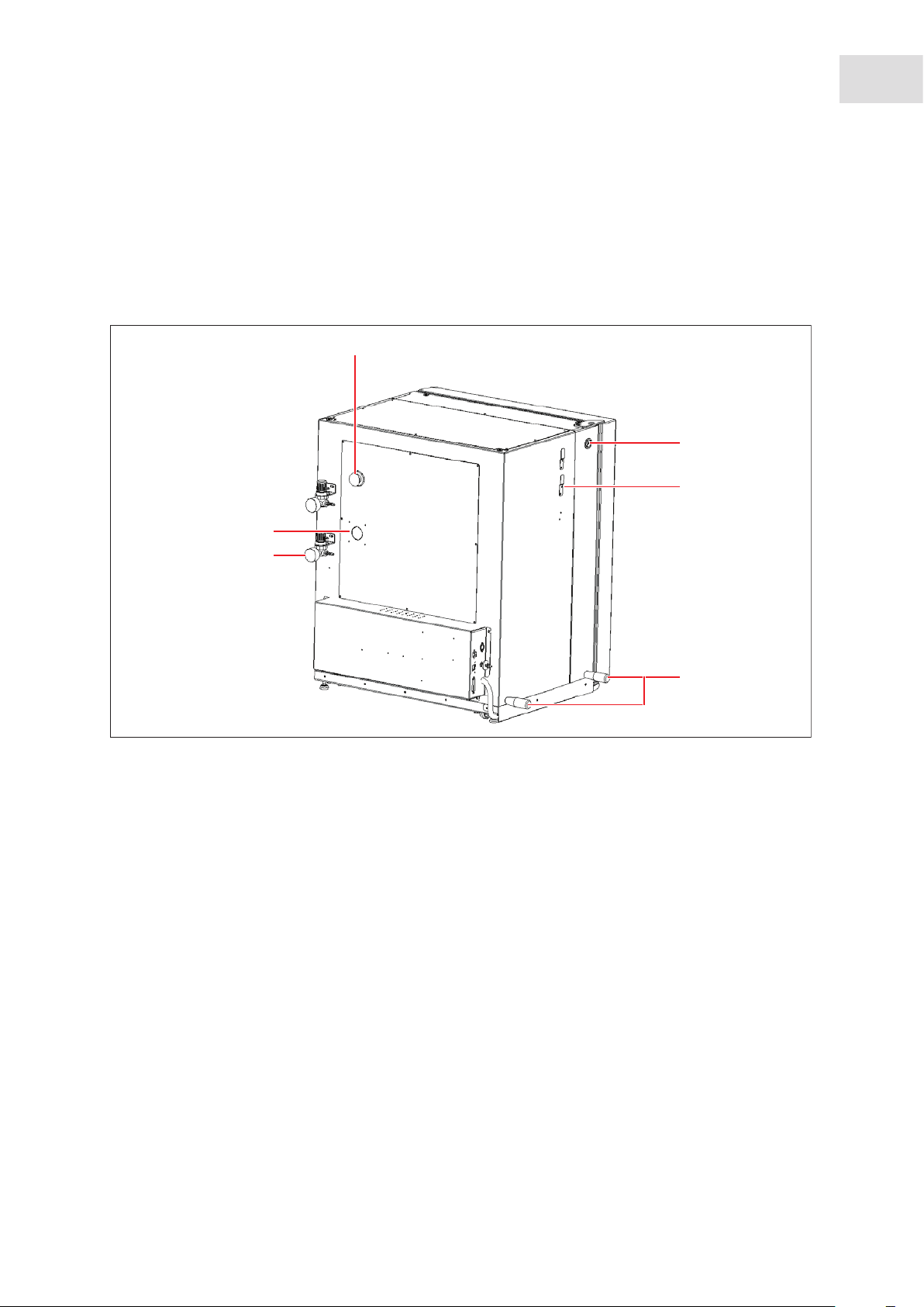
Abb. 5-1: CO2 Incubator rear view
1
2
3
Operation
29
6
5
4
Fig. 5-1: CO2 Incubator rear view
1 Access port
2CO
sample port
2
3 Sensor cover holder
4 Removable lifting handles
5 Location for mounting in-line regulators
sensor location (not shown here)
6O
2
2. Ensure that the white porous sensor cover remains in place.
3. Using the mains/power cord provided, connect the incubator to a earthed/grounded mains/power
supply.
4. Switch the incubator ON using the on/off switch at the rear of the cabinet.
The display will illuminate immediately.
5. Turn on the CO
6. The chamber setpoints are pre-programmed at 37.0 °C and 5 % CO
gas supply with the pressure regulator set to 5 PSI (0.35 bar).
2
. Leave the incubator on until the
2
programmed chamber temperature and CO2 concentration have been reached.
Page 30
30
Operation
®
Galaxy
170 R/170 S CO2 Incubators
English (EN)
• The incubator’s CO
After the temperature setpoint is reached, the CO
valve is disabled until the incubator reaches the temperature setpoint.
2
valve is activated, allowing the
2
incubator to reach the CO2 setpoint.
• If power is interrupted to the incubator long enough for the temperature to drop below
setpoint, the CO
(This serves to avoid spurious CO
valve will be deactivated until temperature setpoint is again achieved.
2
readings while the incubator is below its temperature
2
setpoint)
7. Leave the incubator running for at least two hours (preferably overnight) to allow conditions to stabilize.
5.2 Using the humidity tray
NOTICE! Risk of material damage
To avoid possible damage to the CO
the incubator is switched off, or when a high temperature disinfection cycle is initiated
(optional feature).
Allow a clearance of 50 mm (2 in) to allow access for oxygen sensor (if installed) removal.
• The humidity tray should be left in place at all times.
• Use distilled water only in the humidity tray. Use of any other types of water including
deionized water will cause corrosion inside the incubator.
sensor, never leave water in the humidity tray while
2
If humidification is required:
1. Fill the humidity tray with 1.5 - 2.5 liters of warm (37.0 °C) distilled water.
2. For cell culture work, we recommend adding copper sulphate in the humidity tray. Tests have shown
that, in addition to inhibiting bacterial growth in the tray, this can reduce contamination on the chamber
walls. Add one small teaspoonful (~0.5 g) of copper sulphate to the water in the humidity tray.
3. For sensitive work, we do not recommend the use of any biocide in the humidity tray. To reduce the
possibility of contamination, every 10 to 14 days, empty the tray, clean it with a solution of 70 %
isopropyl alcohol and 30 % distilled water, and then refill it with 1.5 liters of warm distilled water.
The humidity level within the chamber is not adjustable. The internal chamber will reach ~95
% relative humidity at 37 °C using the 1.5-liter humidity tray.
5.3 Operation for optional features
For functionality on optional features (see Available options on p. 64).
Page 31

Operating controls and function for Galaxy 170 R Incubator
®
Galaxy
170 R/170 S CO2 Incubators
6 Operating controls and function for Galaxy 170 R Incubator
6.1 170 R control panel
The control panel consists of an LCD display, five function keys and four direction keys.
Abb. 6-1: Galaxy 170 R control panel (normal operation)
92
31
English (EN)
2
1
3
Fig. 6-1: Galaxy 170 R control panel (normal operation)
1 Function key menu
3 Function keys
Displays the current available screen functions
2 Directional keys
The four Directional Keys will move the cursor
around the screen and adjust values
The HELP file contains most of the information in this operating manual, together with more
detailed troubleshooting information.
The purpose of each Function Key is identified at
the bottom of the display, above the
corresponding key; the function may change from
screen to screen
Page 32

32
Operating controls and function for Galaxy 170 R Incubator
®
Galaxy
English (EN)
170 R/170 S CO2 Incubators
6.2 Programming
6.2.1 Temperature and CO2 level
Perform the following steps to set the desired operating temperature and CO2 level. For more information
on this feature (see Infrared sensor on p. 13).
1. Press the PROG function key.
2. In the PROG screen that appears, press the desired function key, TEMP or CO
direction keys to adjust the value.
If the incubator is supplied with the option of oxygen control, the setpoint for the oxygen level
can be selected and changed like the temperature and CO
3. When the desired setpoint is displayed, press the ENTER function key.
4. After making adjustments (if any were made), allow the incubator to stabilize at the setpoints before
continuing.
If the chamber temperature goes above the temperature setpoint by 1 °C, the
over-temperature system will activate.
setpoints.
2
, then use the and
2
6.2.2 User access code
Programmable user access code allows you to restrict access to the PROG, USER, and ALARM screens
(where settings can be changed) to authorized persons only.
To set the User Access Code (if required):
1. In the PROG screen (accessed by pressing the PROG function key).
The user access code will be displayed as a series of four asterisks.
2. Use the left and right direction keys to move to each code position, and the up and down direction keys
to select a number from 0 to 9.
3. Once the number is selected, press the ENTER function key to save the code.
4. After returning to the main screen, programming access will require the code to make any further
programming changes.
Take care to note your password somewhere. If a password is forgotten, you must contact a
customer service representative to recover or delete the forgotten password.
6.2.3 Removing user access code
1. In the PROG screen, enter the current access code.
2. Now program 0000 as the new access code.
3. Press the ENTER function key to save the change.
The code is now cancelled and programming is no longer restricted.
Page 33

Operating controls and function for Galaxy 170 R Incubator
®
Galaxy
170 R/170 S CO2 Incubators
English (EN)
If the access code has been misplaced, you will be unable to make changes to your incubator’s
settings. Contact customer service or your service representative for instructions on how to
regain access to your incubator.
6.3 Referencing the CO2 sensor with Auto-Zero
Prior to using the incubator, you should manually perform a CO2 Auto-Zero (see PROGRAMMABLE CO2
AUTOZERO on p. 34):
33
1. Perform a CO
p. 34), selecting the PROGRAMMABLE CO
Auto-Zero by pressing the USER function key (see PROGRAMMABLE CO2 AUTOZERO on
2
AUTOZERO, and pressing the START key.
2
2. The incubator will display a countdown as the Auto-Zero is running.
3. When the countdown is complete, the incubator is ready to use.
6.4 USER settings
In the USER screen, you can adjust the features called out on the screen.
Abb. 6-2: USER SETTINGS screen
1
2
Fig. 6-2: USER SETTINGS screen
1 Use the and direction keys to move the
2 Use the ENTER function key to select an option
cursor
This section explains each of the USER screen features. There are other USER options that may be
displayed on screen if they are installed on your incubator. For a list of available options (see Available
options on p. 64).
Page 34

34
Operating controls and function for Galaxy 170 R Incubator
®
Galaxy
170 R/170 S CO2 Incubators
English (EN)
6.4.1 SET DATE AND TIME
The date and time is factory set and will only require adjustment if you are in a different time zone, or when
you change your clocks to Daylight Saving Time and back again to Standard time. You may also select the
style of display for the date.
6.4.2 AUDIBLE ALARM VOLUME ADJUST
The audible alarm volume can be adjusted to your own preferences.
6.4.3 PROGRAMMABLE CO2 AUTOZERO
When you select this feature, the PROGRAM CO2 AUTOZERO screen (see Fig. 6-3 on p. 34) allows you to
program the Auto-Zero frequency and time, or to run the Auto-Zero function manually.
We recommend that you Auto-Zero the CO
system:
2
• Prior to using the incubator for the first time.
• Once a month when your incubator is operating, to ensure that the CO
level is as accurate as possible.
2
• After the incubator has been in storage (or transit) for a while.
The Auto-Zero System automatically re-references the CO
Sensor to atmospheric CO2 in the following
2
way:
1. A pump activates for two minutes, pumping atmosphere at 0.3 liters/minute into the sensor’s measuring
chamber. This displaces the chamber atmosphere completely from the sensor.
Abb. 6-3: PROGRAM CO2 AUTOZERO screen
Fig. 6-3: PROGRAM CO2 AUTOZERO screen
This procedure does not affect the internal chamber environment and will not affect your cell
culture as it is being performed.
2. At the end of the countdown, the control system adjusts the Auto-Zero Factor to reference the sensor to
0.05 % CO
, which is the approximate atmospheric level.
2
3. The pump switches off and the chamber atmosphere diffuses back into the sensor’s measuring
chamber. This takes three minutes, after which the normal CO
control system takes over.
2
Page 35

Operating controls and function for Galaxy 170 R Incubator
®
Galaxy
170 R/170 S CO2 Incubators
English (EN)
4. The result of the Auto-Zero (listed as A/Z on some screens) is sent to the DATALOGGER ALARM
EVENTS screen so that a record of the results will be kept.
The frequency of Auto-Zeroing can be set in steps between once a day and once every 28 days. The default
setting is once every 28 days. If not required, it can be disabled (see DISABLE on p. 35).
The default time setting is 7:00 am. This can be altered to suit your requirements. We recommend that you
only change the time setting shortly before you start to use the incubator.
The Auto-Zero will only occur if the temperature is at setpoint. If the temperature is not at
setpoint, the system will postpone Auto-Zero until the setpoint is achieved.
If the Auto-Zero function is to be run manually, simply press the START function key, within the PROGRAM
AUTOZERO window.
CO
2
6.4.4 DATALOGGER
35
For detailed information (see DATALOGGER screen on p. 36).
6.4.5 POWER FREQUENCY
You can adjust the power frequency to either 50 or 60 Hz to match the local mains/electrical supply. Use the
or direction key until the correct frequency is displayed, then press the ENTER function key.
6.4.6 DISABLE
This feature allows you to inform the control system to ignore certain sensors if their function is not
required. The standard item on this menu is the CO
PRESSURE SWITCH (for Auto-Zeroing). Additional
2
Disable Options appear on this screen according to the options installed on your incubator, (see Available
options on p. 64).
To disable a feature, scroll to OFF using the and direction keys, then press the ENTER function key.
6.4.7 DISINFECTION (optional)
NOTICE! Risk of material damage
The humidity tray MUST be empty and dry before running high-temperature disinfection.
If the incubator is supplied with the High Temperature Disinfection option, the menu item DISINFECTION
will be displayed. This feature activates the disinfection cycle of the incubator.
The disinfection cycle heats the inner chamber to 120 °C, holds that temperature for 4 hours, then cools the
chamber to the selected temperature setpoint. All of the interior components (with the exception of the O
sensors, if present) can be left in place during the cycle to ensure that everything within the chamber is
2
Page 36

36
Operating controls and function for Galaxy 170 R Incubator
®
Galaxy
170 R/170 S CO2 Incubators
English (EN)
disinfected prior to resumption of activity. For a full explanation of this feature, (see High temperature
disinfection option with oxygen control on p. 71).
6.5 DATALOGGER screen
The DATALOGGER screen displays the following information:
Abb. 6-4: DATALOGGER screen
Fig. 6-4: DATALOGGER screen
6.5.1 ALARM EVENTS
The following alarm events are recorded in the order in which they occurred, with the most recent event
displayed at the top:
• Power ON/OFF
• Chamber Temperature High/Low (programmed value)
Level High/Low (programmed value)
•CO
2
Supply Failure
•CO
2
• All System Alarms
Auto-Zero (A/Z) Adjustments
•CO
2
•CO
Auto Gain (A/G) Adjustments (reserved for use by authorized service technicians only)
2
• Oxygen and Relative Humidity (R/H) Alarms (where these options are installed)
The capacity is 99 events, after which the earliest event is overwritten and a later event is added.
The date and the time are also recorded for each event, (see Fig. 6-5 on p. 37):
Page 37

Operating controls and function for Galaxy 170 R Incubator
Abb. 6-5: ALARM EVENTS screen
Fig. 6-5: ALARM EVENTS screen
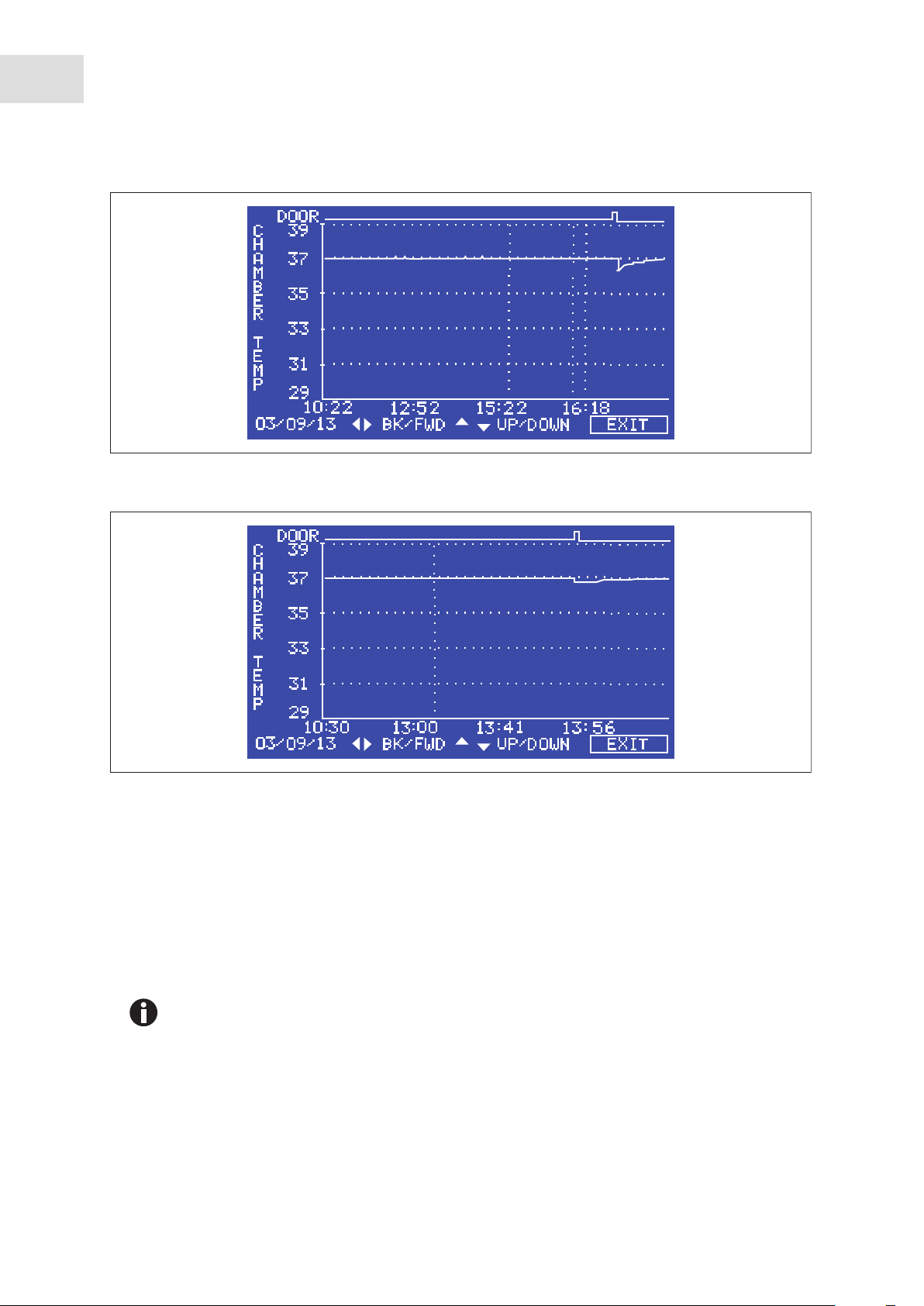
6.5.2 TEMPERATURE GRAPH + DOOR OPEN BAR CHART
Galaxy
®
170 R/170 S CO2 Incubators
English (EN)
37
When you select this from the DATALOGGER screen, the Door Open bar chart is shown at the top of the
screen to associate it with a temperature disturbance (see Fig. 6-6 on p. 38). A temperature reading is
recorded every 18 seconds while the temperature is outside the specification of ±0.1 °C and each reading is
shown as a single pixel.
When the temperature has settled within specification, the recording is compressed to one pixel
representing (10) 18-second readings (as long as the temperature remains in specification). This allows up
to 10 hours of readings to be displayed on one screen. When the temperature moves outside specification,
for instance if the door is opened, the graph reverts to individual 18-second readings until temperature is
within specification again.
When the data is compressed or decompressed, a light dotted line is displayed vertically on the screen to
signify that the time axis is changing from 18-second to 10 x 18-second increments or vice versa (see
Fig. 6-7 on p. 38).
A heavy dotted line (not shown) is displayed when the incubator is switched on.
Page 38
38
Operating controls and function for Galaxy 170 R Incubator
®
Galaxy
170 R/170 S CO2 Incubators
English (EN)
Abb. 6-6: TEMPERATURE GRAPH + DOOR OPEN BAR CHART screen
Fig. 6-6: TEMPERATURE GRAPH + DOOR OPEN BAR CHART screen
Abb. 6-7: Dotted vertical line showing compressed/decompressed data.
Fig. 6-7: Dotted vertical line showing compressed/decompressed data.
Compressing data allows memory space to be maximized. Once the memory space has been filled, the
earliest events are overwritten as they are replaced by the latest recording.
6.5.3 CO2 GRAPH + DOOR OPEN BAR CHART
These graphs record in a way similar to the Chamber Temperature graphs. The specification for CO2 is ±
0.1 %.
Both CO
and temperature graphs share the same time axis. If the time axis changes to
2
accommodate data in one graph, it will also change in the other graph.
6.5.4 DIAGNOSTIC CHAMBER ELEMENT GRAPH
This graph records chamber element temperature over time to assist troubleshooting.
Page 39

Operating controls and function for Galaxy 170 R Incubator
®
Galaxy
170 R/170 S CO2 Incubators
English (EN)
6.5.5 DIAGNOSTIC DOOR GRAPH
This graph records the door’s inner surface temperature over time to assist troubleshooting.
6.5.6 DIAGNOSTIC DOOR ELEMENT GRAPH
This graph records door element temperature over time to assist troubleshooting.
6.5.7 RESTART GRAPHIC RECORD
This feature removes the current graph and begins a new one. The data cannot be recovered once it is
deleted.
6.6 CHAMBER ALARMS menu screen
39
The CHAMBER ALARMS programming screen (see Fig. 6-8 on p. 39) allows the various alarm options to be
selected and modified. Press the or direction key to move around the options and the or
direction key to adjust values. The temperature and CO
to within ± 0.5 of the temperature and CO
Abb. 6-8: CHAMBER ALARMS screen
setpoints. The alarm setpoints can also be manually adjusted.
2
High and Low Alarm setpoints automatically adjust
2
Fig. 6-8: CHAMBER ALARMS screen
To arm the chamber alarms after a selectable delay:
1. Choose the option ARM ALARMS WHEN AT SETPOINT.
2. Select NO for both TEMP and CO
(see Fig. 6-8 on p. 39).
2
3. Choose the option DELAY IN ARMING AFTER DOOR OPEN and select the desired delay (15 minutes in
the sample screen (Fig. 6-8 on p. 39)) to allow for temperature and CO
recovery after the door has been
2
opened.
Alternatively, the alarm system can be set to re-arm only after the original temperature and CO
have been achieved:
1. Choose the option ARM ALARMS WHEN AT SETPOINT.
setpoints
2
Page 40

40
Operating controls and function for Galaxy 170 R Incubator
®
Galaxy
170 R/170 S CO2 Incubators
English (EN)
2. Select YES for both TEMP and CO2.
3. When YES is selected for this function, the DELAY IN ARMING AFTER DOOR OPEN is ignored.
A DOOR OPEN ALARM: can be adjusted, choosing from seven preset durations (45 seconds in (Fig. 6-8 on
p. 39)) to warn of an improperly closed door.
The AUDIBLE and VISUAL alarms can be adjusted from OFF to ON (which means the alarm will be on
continuously until it is acknowledged) in seven preset time increments.
In the OFF position, any Chamber Alarms that occur will be displayed on the screen without flashing and
with the audible alarm inhibited (see Chamber alarm system function on p. 40).
6.6.1 Chamber alarm system function
When the incubator is switched ON, or after the temperature and CO2 levels have been re-programmed, the
alarm system is inactive until the setpoint values are achieved (within ± 0.1), after which the alarm system
is armed. CO
and temperature alarms are individually armed.
2
If temperature and/or CO
levels deviate more than the programmed setpoints, the display flashes, the
2
audible alarm sounds and a message appears on the screen (see Fig. 6-9 on p. 40). Acknowledge the alarm
by pressing any key.
Abb. 6-9: CHAMBER ALARM message
Fig. 6-9: CHAMBER ALARM message
After setpoints have been achieved for the first time, when the outer door is opened, the alarm system is
disabled; on closing the door, if selected, a programmable alarm delay starts:
• If chamber conditions recover within the programmed alarm delay time, the alarm system is
immediately re-armed. After the delay, the alarm system is armed and if the temperature and CO
are
2
outside the alarm high and low settings, the alarm will be activated.
• If an alarm occurs and the chamber subsequently recovers, the alarm stops and the system is re-armed.
Details of the alarm event are stored in the datalogger.
If the CO
valve is opened and no pressure is detected, an alarm occurs and a warning message appears on
2
the screen, alerting you to CHECK CO
SUPPLY (see Fig. 6-10 on p. 41).
2
Page 41

Operating controls and function for Galaxy 170 R Incubator
Abb. 6-10: CHAMBER ALARM to check CO2 supply
Fig. 6-10: CHAMBER ALARM to check CO2 supply
Instructions to remedy the alarm are provided in the ALARM screen.
Galaxy
®
170 R/170 S CO2 Incubators
English (EN)
41
6.7 DIAGNOSTICS menu screen
The diagnostics screen contains technical information regarding the status of many of the system
components found on the incubator. This screen is mainly for technical service use, and can be used to
troubleshoot the incubator systems before service is scheduled. This information allows technical support
to optimize the service support required, and to shorten service time.
Abb. 6-11: DIAGNOSTICS screen
Fig. 6-11: DIAGNOSTICS screen
Page 42

42
Operating controls and function for Galaxy 170 R Incubator
®
Galaxy
170 R/170 S CO2 Incubators
English (EN)
6.8 HELP MENU screen
The HELP MENU screen provides user-selectable categories of abbreviated information found in the user
manual. All the major systems are covered in the help menu, including help on installing the incubator. If
the user manual is misplaced, information about the CO
on-screen.
Abb. 6-12: HELP MENU Screen
incubator and its functions can always be found
2
Fig. 6-12: HELP MENU Screen
Page 43

Operating controls and function for Galaxy 170 S Incubator
®
Galaxy
170 R/170 S CO2 Incubators
7 Operating controls and function for Galaxy 170 S Incubator
7.1 170 S control panel
The control panel consists of two individual three-digit LED displays, and four function keys:
Abb. 7-1: Galaxy 170 S control panel (normal operation)
43
English (EN)
1
Fig. 7-1: Galaxy 170 S control panel (normal operation)
1 Temperature display
2CO
display
2
4 Enter (function key)
3 Up (function key)
In Programming mode, use this key to scroll up
through numbered values in the display
5 Down (function key)
2
3
4
5
6
Press this key to save a new setpoint. Press this
key simultaneously with the Down key to access
the Alarm system
In Programming mode, use this key to scroll
down through numbered values in the display.
Press this key simultaneously with the Enter key
to access the Alarm system
6 Programming (function key)
Press this key to enter Programming mode, and
to set values in either display
If you accidentally press both the Up and Down keys simultaneously, you will engage
Engineering Mode: press the Programming key immediately to exit.
Page 44

44
Operating controls and function for Galaxy 170 S Incubator
®
Galaxy
170 R/170 S CO2 Incubators
English (EN)
7.2 Setting temperature and CO
2
Perform the following steps to program the temperature and CO2 setpoints. Temperature and CO2 may be
set within the ranges shown in the following table:
Tab. 7-1: Setting temperature and CO
2
Parameter Available Setpoint Range
Temperature 10 °C to 50 °C (must be at least 4 °C above ambient)
CO
2
0.2 % to 20 %
To set the Temperature:
1. Press the Programming ( * ) key.
The temperature display will flash.
2. Press the Up ( ) or Down ( ) key until the desired value appears in the left-hand display.
3. Press the Enter key to save the setpoint.
The CO
To set the CO
display will flash.
2
level:
2
1. Press the up ( ) or down ( ) key until the desired value appears in the right-hand display.
2. Press the Enter key to save the setpoint.
To change the CO
work in the CO
level without adjusting the temperature setpoint, press the Programming ( * ) key to
2
display, then press the Enter key.
2
Allow the incubator to stabilize at the setpoints selected before continuing.
7.3 Programming the alarm system
7.3.1 Setting the high and low temperature alarms
1. Press the Enter and keys simultaneously to enter the alarm menu.
The display will show: °C.AL.
2. Press the Enter key to display the High Temperature Alarm, HI 37.5. The factory setting is the setpoint
value (37.0 °C) + 0.5 °C.
3. Use the Up ( ) or Down ( ) key to adjust the High Temperature Alarm. The minimum setting is 0.5 °C
from setpoint.
4. Press the Enter key to save the setting.
The Low Temperature Alarm is displayed, LO 36.5. The factory setting is the setpoint value (37.0 °C) -
0.5 °C.
5. Use the Up ( ) or Down ( ) key to adjust the value.
Page 45

Operating controls and function for Galaxy 170 S Incubator
®
Galaxy
170 R/170 S CO2 Incubators
English (EN)
6. Press the Enter key to accept the setting.
7. Press the Programming ( * ) key twice to exit the menu.
7.3.2 Setting the CO2 high and low alarms
1. Press the Enter and keys simultaneously to enter the alarm menu.
The display will show: °C.AL.
2. Press the key until the display shows: CO2AL.
3. Press the Enter key to display HI.5.5. The factory setting is the setpoint value (5.0 %) + 0.5 %.
45
4. If you wish to adjust the High CO
Alarm, use the or key. The minimum setting is 0.5 % from
2
setpoint.
5. Press the Enter key to save the setting.
The low CO
Alarm is displayed, LO 4.5. The factory setting is the setpoint value (5.0 %) - 0.5 %.
2
6. Use the the or key to adjust the value.
7. Press the Enter key to accept the setting.
8. Press the Programming ( * ) key twice to exit the menu.
If the CO
setpoint is programmed at 0.0 % and high and low alarms are accessed, the high
2
will display “0.5” and the low will display “Off”.
7.3.3 Door open alarm
When the door is opened, an alarm will sound after a preset time delay. To adjust the time delay:
1. Press the Enter and keys simultaneously to enter Alarm Program Mode.
The display will show: °C.AL.
2. Press the key until the display shows DOO.RAL (reading across both displays).
3. Press the enter key and the and keys to adjust the time (as you scroll through the available choices,
you will see 15, 30, 45, 60, 75, 90 seconds, then OFF).
4. Press the Enter key to save the desired value.
5. Press the Programming ( * ) key twice to exit the menu.
7.3.4 Alarm duration
Perform the following steps to adjust the alarm duration:
1. Press the Enter and keys simultaneously to enter Alarm Program Mode.
The display will show: °C.AL.
2. Press the key until the display shows PER.IOD (reading across both displays).
3. Press the Enter key and the and keys to adjust the Alarm duration.
Page 46

46
Operating controls and function for Galaxy 170 S Incubator
®
Galaxy
170 R/170 S CO2 Incubators
English (EN)
As you scroll through the available choices, you will see OFF, 10 sec, 30 sec, 60 sec, 600 sec, 1 HR, then
ON).
4. Press the Enter key to select the desired value.
5. Press the Programming ( * ) key twice to exit the menu.
7.3.5 Alarm arming delay
The alarm arming delay is the length of time that is allowed for the Temperature and CO2 to recover after
opening the incubator before the Alarm System is armed again. This helps to prevent unnecessary alarms
from occurring.
To change the delay:
1. Press the Enter and keys simultaneously to enter Alarm Program Mode.
The display will show: °C.AL.
2. Press the key until the display shows DR .DEL (across both windows).
3. Press the Enter key and the and keys to adjust the Alarm Arming time.
As you scroll through the available choices, you will see 0.15 Hr, 0.20, 0.30, 1.00 , then OFF.
4. Press Enter to select the desired value.
5. Press ( * ) to return to the main alarm programming menu, and press ( * ) again to return to the main
display.
When alarm delay is set to OFF, the Alarms will arm only when the programmed setpoint is
reached.
7.4 Chamber alarm system
When the incubator is switched ON, or after any values have been reprogrammed, the Alarm System is
inactive until the setpoint values (± 0.1) are achieved, after which the Alarm System is armed.
If temperature and/or CO
audible alarm sounds and a message appears on the screen. You can acknowledge (and cancel) the alarm
by pressing any key.
When the outer door is opened, the Alarm System is disabled. When you close the door, the preset Alarm
Arming Delay starts. When the delay time expires, the Alarm System is re-armed; if the temperature and/or
fall below or above the alarm setpoints, the alarm will be activated. If chamber conditions recover
CO
2
within the Alarm Arming Delay time, the Alarm System will be re-armed but no alarm will be activated.
levels deviate more than the programmed amount, the display flashes, the
2
If an alarm is not acknowledged but the chamber conditions subsequently recover, the audible alarm will be
cancelled but the alarm message will remain on the screen to alert the user to the fact that an alarm has
occurred. You can cancel this alarm message by pressing any key. The duration of the audible alarm can be
adjusted from inactive to continuous (see Alarm duration on p. 45).
Page 47

Operating controls and function for Galaxy 170 S Incubator
Galaxy
®
170 R/170 S CO2 Incubators
English (EN)
7.4.1 Temperature sensor system alarms
There are six temperature sensors: two in the chamber, two in the door and two in the base. If any of these
sensors should fail, the following message will appear: ºC F.AIL.
Because the incubator can no longer control temperature properly without the failed sensor, the heating
will switch off and the incubator will cool down to room temperature.
If, however, a sensor fails but subsequently corrects itself, the temperature control will restart and an alarm
message will remain on the temperature side of the display: SAL … (meaning Sensor Alarm).
This message can be cancelled by pressing any key.
7.4.2 Over-temperature cut-out and alarm
This alarm only occurs if the chamber temperature exceeds the temperature setpoint by 1 °C or if one of the
heating elements exceeds a specific activation threshold. The activation threshold is set at the factory and
cannot be adjusted.
47
Following activation, the over-temperature cut-out and alarm system operates in two sequential modes:
Mode 1: The over-temperature cut-out and alarm activates and cuts power to the heating elements and the
control valve. The condition is shown on the display by the message °Ctrip. When the chamber
CO
2
temperature has fallen to the programmed setpoint, the system changes to Mode 2.
Mode 2: The control system then tries to maintain the chamber temperature at the programmed level by
switching the heating elements on and off, using an emergency control method that is, however, less
precise. The message TAL will flash on-screen to signal that an over-temperature fault occurred and the
incubator is being controlled by the emergency control system. This message cannot be cancelled via the
keypad.
Normal temperature control can be regained and the over-temperature cutout and alarm can be cancelled
by reprogramming the temperature, opening and closing the glass door, or switching the incubator off and
back on.
If the problem persists, the alarm will recur; if this happens, please contact your service representative or
your distributor immediately.
7.5 CO2 Auto-zero system
Perform the following steps to carry out an auto-zero and reference the CO2 sensor to atmospheric CO
2
7.5.1 Auto-zero
1. Press the Enter and Programming ( * ) keys simultaneously.
A prompt will appear:
ENT.ER STA.RTS CO2 AUT.O ZER.O
Page 48

48
Operating controls and function for Galaxy 170 S Incubator
®
Galaxy
170 R/170 S CO2 Incubators
English (EN)
2. Press the Enter key to begin the cycle.
The Auto Zero System automatically re-references the CO
Sensor to atmospheric CO2 in the following
2
way:
• A small pump switches on for 2 minutes pumping filtered atmosphere at 0.3 liters/minute into the
measuring chamber of the sensor. This displaces the chamber atmosphere completely from the
sensor.
• At the end of the countdown, the Control System adjusts the auto-zero factor to reference the sensor
to 0.05 % CO
which is the approximate atmospheric level.
2
• The pump switches off and chamber atmosphere moves back into the measuring chamber of the
sensor. This takes 3 minutes after which the normal CO
control takes over.
2
• On completion of the auto-zero a prompt will appear:
CO2 AUT.O ZER.O IN RAN.GE
3. Press the ( * ) key to finish the cycle and return to the main display.
If the CO
Auto-Zero cannot reference the signal to atmosphere at the end of the Auto-Zero, the
2
following message will appear:
CO2 AUT.O ZER.O FAI.LED
This means that the CO
sensor is defective and requires replacement. If this occurs, please contact
2
your local distributor immediately.
The default setting for the auto-zero system is 28 days of running time for the incubator. After the incubator
has been switched on for a total of 28 days (672 hours), the auto-zero will automatically take place.
7.5.2 Changing auto-zero frequency
To change the frequency of the auto-zero
1. Press the Enter and ▲ keys simultaneously.
The following message will be displayed: PRG.A2.
2. Press Enter.
The display changes to 28 DAY.
By pressing the ( * ) and enter keys this value can be changed in steps from 28 to 14, 7, 1 or OFF.
3. Press Enter to confirm the new setting.
If a CO
CO
If after a 15-minute delay, the CO
In the event of high CO
below setpoint. Also check that the CO
alarm occurs, the auto-zero will automatically take place after 1 minute. This is to confirm that the
2
sensor is correctly referenced.
2
is still in an alarm condition and re-alarms, it will again auto-zero.
2
alarms, open the inner door for a few seconds to ensure that the CO2 level drops
2
pressure is set correctly to 5 PSI (0.35 bar).
2
In the event of low CO
alarms, check that the CO2 supply is present and set to the correct pressure.
2
Page 49

Operating controls and function for Galaxy 170 S Incubator
®
Galaxy
170 R/170 S CO2 Incubators
English (EN)
7.5.3 High temperature disinfection operation
For high temperature disinfection information (see Using the high temperature disinfection (Galaxy S) on
p. 70).
49
Page 50

50
Operating controls and function for Galaxy 170 S Incubator
®
Galaxy
170 R/170 S CO2 Incubators
English (EN)
Page 51

Maintenance
English (EN)
Galaxy
®
170 R/170 S CO2 Incubators
8 Maintenance
8.1 Routine maintenance
8.1.1 General
WARNING! Risk of injury to personnel or damage to equipment!
Two stacked incubators should not be moved for maintenance or cleaning.
To ensure that chamber conditions remain stable, minimize the length of time that the door is open. When
you open the door, wipe off any condensation that may have formed on the inner seal to avoid condensation
build-up.
If you are using the humidity tray for humidification, (see Using the humidity tray on p. 30).
51
If you have two incubators stacked, the upper incubator does not have to be moved when you
are servicing the lower incubator.
8.1.2 Daily Checks
1. Check that the temperature and CO2 levels are reading within specification.
2. Check the reserve pressure in the CO
incubator ensures very low consumption of CO
cylinder should last approximately 12 months (frequent door openings will deplete the supply more
rapidly). If there is a significant drop at the cylinder pressure of 725 PSI (50 bar), it means that the
cylinder is almost empty and should be replaced. Ensuring that there are no leaks at any of the
connections will ensure a greater lifetime to the CO
.
of CO
2
3. Any spills in the chamber should be cleaned immediately.
4. Check the DATALOGGER screen for any alarms or events that may have occurred overnight.
cylinder (normally 725 PSI (50 bar) when full). The design of the
2
: during normal working conditions, a typical large
2
supply and will help avoid accidentally running out
2
8.1.3 Weekly checks
Use distilled water only in the humidity tray. Use of any other types of water including
deionized water will cause corrosion inside the incubator.
Refill the humidity tray with 1.5 - 2.5 liters of warm (~ 37.0 °C) distilled water. The use of warm water will
ensure a rapid return to optimum chamber conditions.
8.1.4 Monthly checks
We recommend routine replacement of the water in the humidity tray, and that you clean the tray at the
same time.
Page 52

52
Maintenance
®
Galaxy
170 R/170 S CO2 Incubators
English (EN)
If required, you can take a sample of the gas inside the chamber using the CO2 sample port, and check it
using a CO
gas analyzer (see Accessories on p. 63)(see CO2 Sampling with analyzer on p. 52).
2
Displayed chamber CO
is complete. This is merely a sensor characteristic; the CO
level will drop during sampling, but it will recover once the sampling
2
level in the chamber is actually not
2
affected.
We recommend that you perform a CO
you Auto-Zero the CO
system at least once every 28 days to ensure that CO2 level is correct.
2
Auto-Zero prior to sampling. We also recommend that
2
8.1.5 CO2 Sampling with analyzer
The CO2 sample port is located on the left-hand side of the incubator, near the top (see Fig. 5-1 on p. 29).
If you conduct a sampling, please ensure the following:
• Turn off the CO
gas by re-programming the setpoint for CO2 to 0.0 % to prevent CO2 from being
2
injected into the chamber and giving a false reading.
• A flow rate ≤ 0.5 liters/minute is used to take a sample.
• The door is kept closed.
• Reset the CO
setpoint to the desired level after sampling.
2
We recommend that you perform a CO
you Auto-Zero the CO
system at least once every 28 days to ensure that CO2 level is correct.
2
2
Auto-Zero prior to sampling. We also recommend that
8.1.6 Routine checks of the O2 control option (170 R only)
Be sure to conduct the reference to atmospheric oxygen procedure on a monthly basis to ensure that
long-term drift in output from the sensor will be corrected, and to determine when the sensor requires
replacement.
Under normal humidity conditions (95 - 99 % RH), the sensor is unaffected. If for any reason (such as a
large spill inside the chamber or the incubator being switched off while fully humidified) liquid condenses
around the sensor, the result may be restriction of gas flow and a low sensor signal. Should such
condensation appear on the chamber walls, normal operation can be easily restored by removing the
humidity tray, drying the chamber completely, and then running the incubator at 37 °C for one hour. This
will dry out the sensor. After the hour has elapsed, the humidity tray can be reinstalled and the incubator
humidified again.
Change the hydrophobic filter each time you clean the incubator, to avoid contamination or clogging over
time.
Page 53
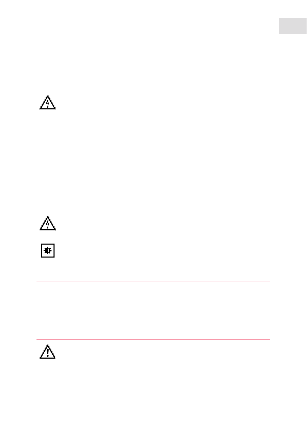
Maintenance
English (EN)
Galaxy
®
170 R/170 S CO2 Incubators
8.2 Service
8.2.1 Fuse replacement
DANGER! Electric shock
Switch the device off and pull the power plug out of the socket before beginning work.
To replace a fuse, you will need a flat-bladed (5 mm maximum) screwdriver.
1. Using the flat-bladed screwdriver, rotate the fuse holder (see Fig. 4-7 on p. 27) counter-clockwise until
the fuse holder springs out.
2. Remove the spent fuse.
3. Install a new fuse of the same type.
4. Orient the fuse holder back in the side panel and, using the screwdriver, turn clockwise to secure it in
place.
53
8.3 Cleaning
DANGER! Electric shock
Switch the device off and pull the power plug out of the socket before beginning work.
NOTICE! Damage due to incorrect cleaning agent or sharp objects
Unsuitable cleaning agents can damage the display, surfaces and printing.
Never use corrosive cleaning agents, strong solvents or abrasive polishes.
Do not use acetone to clean the device.
Do not use sharp objects to clean the device.
1. Routinely clean the exterior of the incubator by wiping it over with a soft cloth, moistened with soapy
water.
2. Rinse the soap from the cloth in clean water, and wipe the exterior surfaces again.
8.4 Disinfection/Decontamination
DANGER! Danger from exposure to decontamination agents.
Wear appropriate laboratory clothing, protective gloves and safety glasses.
Wear breathing protection if you work with particulate matter.
Page 54

54
Maintenance
®
Galaxy
170 R/170 S CO2 Incubators
English (EN)
NOTICE! Risk of material damage
Never use any of the following substances to clean the stainless steel, or damage will
result: Sodium Azide, Aqua Regia, Iodine, Ferric Chloride or Sulphuric Acid.
Use the decontamination method recommended by the manufacturer.
If you would like to use a different method, contact Eppendorf to prevent the device from
becoming damaged.
If you have any further questions regarding the cleaning and disinfection or decontamination
and the cleaning agents to be used, contact Eppendorf.
The contact details are provided on the back of this manual.
NOTICE! Risk of material damage
It is very important to ensure that no liquid is spilled onto the white porous CO
sensor
2
cover at the rear of the chamber. Failure to use the protective cover(s) could result in
damage to the sensor(s) and may affect your warranty.
Use distilled water only in the humidity tray. Use of any other types of water included
deionized water will cause corrosion inside the incubator.
The recommended disinfecting agent for use with the incubator is a solution of 70 % isopropanol
(isopropyl alcohol) and 30 % distilled water. Be sure to follow appropriate safety regulations while you are
using this solution.
To best protect yourself, your incubator and your work area, follow these instructions:
1. Program 0.0 % CO
and switch off the incubator. Unplug the incubator from the mains/power supply.
2
external
2. Dampen a clean cloth with the alcohol solution and wipe down all surfaces, taking care to keep the
alcohol solution from coming into contact with any mains/electrical outlets or assemblies.
3. Remove all of the shelves, the humidity tray, and the shelf racks.
4. Place the black protective cover over the CO
sensor. Also protect any additional sensors, such as
2
Oxygen or Humidity, with the cover(s) supplied.
5. You can clean the humidity tray by rinsing it in sterile water, wiping it down with the alcohol solution,
and then rinsing it again with sterile water.
6. Wipe down the inside of the chamber with the alcohol/water solution, and leave it to dry completely.
internal
7. Wipe the components of the chamber twice with the alcohol/water solution. Wipe off excess liquid and
leave it to dry completely.
8. Reassemble the shelf racks, shelves, and humidity tray before switching the incubator on. Wipe the
inner door seal with the alcohol solution, rinse and leave it to dry.
9. Ensure the protective cover(s) are removed from all sensor(s) and replaced in the holder for
safekeeping. Be very careful, as you remove the black CO
sensor cover, not to accidentally remove the
2
white porous sensor cover. This must remain in place.
Page 55

®
Galaxy
170 R/170 S CO2 Incubators
English (EN)
10.Refill the humidity tray (see Using the humidity tray on p. 30). When you reinstall it, ensure that the
humidity tray is pushed fully back.
11.Leave the incubator on for at least two hours (preferably overnight) to allow conditions to stabilize.
Maintenance
12.When the incubator has stabilized, carry out an Auto-Zero and reprogram the desired CO
be necessary to open the glass door briefly if, after performing an Auto-Zero, the CO
level. It may
2
level is too high.
2
8.5 High temperature disinfection
If your incubator is supplied with the High Temperature Disinfection option, follow the guidelines outlined
for operation, (see Using the high temperature disinfection (Galaxy R) on p. 68) or (see Using the high
temperature disinfection (Galaxy S) on p. 70) for information on how to correctly and safely operate this
option.
55
Page 56

56
Maintenance
®
Galaxy
170 R/170 S CO2 Incubators
English (EN)
Page 57
9 Transport, storage and disposal
9.1 Transport
NOTICE! Risk of material damage
Never try to lift the incubator by its door; this would cause permanent damage to the
incubator.
9.2 Storage
Store incubator in ambient conditions of 10 °C - 50 °C.
Transport, storage and disposal
®
Galaxy
170 R/170 S CO2 Incubators
English (EN)
57
9.3 Disposal
In case the product is to be disposed of, the relevant legal regulations are to be observed.
Information on the disposal of electrical and electronic devices in the European Community:
Within the European Community, the disposal of electrical devices is regulated by national regulations
based on EU Directive 2002/96/EC pertaining to waste electrical and electronic equipment (WEEE).
According to these regulations, any devices supplied after August 13, 2005, in the business-to-business
sphere, to which this product is assigned, may no longer be disposed of in municipal or domestic waste. To
document this, they have been marked with the following identification:
Because disposal regulations may differ from one country to another within the EU, please contact your
supplier if necessary.
In Germany, this is mandatory from March 23, 2006. From this date, the manufacturer has to offer a
suitable method of return for all devices supplied after August 13, 2005. For all devices supplied before
August 13, 2005, the last user is responsible for the correct disposal.
Page 58

58
Transport, storage and disposal
®
Galaxy
170 R/170 S CO2 Incubators
English (EN)
Page 59

®
Galaxy
10 Technical data
10.1 Weight/dimensions
10.1.1 Equipment dimensions
Width 68.5 cm (27 in)
Height 84.3 cm (33.2 in)
Depth 67.7 cm (26.7 in)
Weight 90 kg (198.4 lb)
10.1.2 Internal dimensions
Width 53.3 cm (21.0 in)
Height 69.3 cm (27.3 in)
Depth 44.4 cm (17.5 in)
Volume 174 liters
Technical data
170 R/170 S CO2 Incubators
English (EN)
59
10.1.3 Transporting dimensions
Width 83.0 cm (33 in), pallet included
Height 110.0 cm (43 in), pallet included
Depth 83.0 cm (33 in), pallet included
Weight 108 kg (238 lb)
10.1.4 Shelves
Width 52.0 cm (20.5 in)
Depth 42.6 cm (16.8 in)
Number of shelves (170 R) Multi-position shelve option (standard)
Number of shelves (170 S) 4 standard; upgrade to 8 shelves with multiple
position option available
Page 60

60
Technical data
®
Galaxy
English (EN)
170 R/170 S CO2 Incubators
10.2 Power supply
10.2.1 Mains/electrical supply
Mains/power connection 120 V, 50 Hz
120 V, 60 Hz
230 V, 50 Hz
230 V, 60 Hz
Power consumption for 120 V 1300 W
Power consumption for 230 V 1600 W
Energy to maintain 37 °C < 0.1 kWh
10.3 Fuses
fuse for 120 V 10 A
fuse for 230 V 8 A
10.4 Ambient conditions
Ambient conditions 15 °C - 28 °C
10.4.1 Temperature management
• Digital programming via microprocessor control in 0.1 °C increments. Measurement of chamber and
door temperature via 6 RT (Resistance Temperature curve) matched thermistors (sensitivity 0.01 °C)
• Adjustable independent control of door heater
• “Out of Limits” temperature protection system independent of microprocessor control.
Range 4 °C above ambient temperature to 50 °C
Control ± 0.1 °C
Stability ± 0.1 °C at 37 °C
Uniformity ± 0.3 °C at ambient 20°C - 25 °C
If ambient temperature is close to the programmed value, control settings may need adjusting.
Please consult Eppendorf Service for instructions.
Page 61

Technical data
English (EN)
Galaxy
®
170 R/170 S CO2 Incubators
10.4.2 CO2 control
Solid-state infrared CO2 sensor operating independent of humidity. Programmable, fully automatic zeroing
function.
Range 0.2 - 20 %
Control ± 0.1 %
Stability ± 0.2 % at 5 % CO
Uniformity ± 0.1 %
Gas connections 6 mm tubing
Required gas pressure 5 PSI (0.35 bar)
2
10.4.3 Relative humidity
61
Removable stainless steel humidity tray.
Reservoir capacity 2.5 liters
Humidity control Normal: 95 % at 37 °C
10.4.4 Altitude limit
Altitude limit 2000 m (2187.23 yd)
10.4.5 Storage temperature
Air temperature 10 - 50 °C
10.4.6 Calibration
Maximum operating ambient temperature is 28 °C.
Factory calibration of the incubator is carried out at 37 °C, 5.0 % CO
an ambient temperature of 20 - 25 °C with no heat-generating apparatus inside the chamber.
Software calibration adjustments may be required to optimize performance if the incubator is being used
well outside these operating conditions. Performance specifications may also be affected.
and 90 to 95 % RH, in
2
For advice on calibration adjustments and relevant performance specifications, contact Eppendorf service.
Please be prepared with the model and serial number of your incubator and the complete details of your
operating conditions.
Page 62

62
Technical data
®
Galaxy
170 R/170 S CO2 Incubators
English (EN)
Page 63

®
Galaxy
170 R/170 S CO2 Incubators
11 Ordering information
11.1 Accessories
Contact Eppendorf sales for ordering information.
Description Quantity
Two Stage CO2 Regulator 1
Two Stage N2 Regulator 1
Supply Line Filter 1
CO
2
CO2 In-line Pressure Regulator 1
Cylinder Auto-Changeover Controller 1
CO
2
Auto-Zero Filter 1
BioCommand SFI 1
Oxygen Sensor Zeroing Kit 1
Electronic CO
Electronic CO2 and O2 Gas Analyzer 1
Gas Analyzer 1
2
Ordering information
63
English (EN)
Electronic CO2/ O2 and RH Analyzer 1
Additional Shelf, Perforated 1
Additional Shelf, Non-Perforated 1
Additional Humidity Pan 1
Stacking Kit and Stand (lower and upper stacking frame with casters) 1
Lower Stacking Frame with Castors 1
Spare CO
Sensor 1
2
Spare O2 Sensor 1
Page 64

64
Ordering information
®
Galaxy
170 R/170 S CO2 Incubators
English (EN)
11.2 Available options
Some option combinations are not possible, others may incur extra cost. Contact Eppendorf sales for
ordering information.
Options
Cooling System
Galaxy 170 R BMS Relay
Galaxy 170 S BMS Relay
O
Control, 0.1 - 19 %
2
O2 Control, 1 - 95 % (170 R only)
IP66 Power Receptacle
Copper Chamber
4 Split Inner Door*
8 Split Inner Door* (recommended for device with O
Humidity Alert and Monitoring Package
control)
2
*Four and eight inner glass door options are available, to match the shelves installed, which help to reduce
the loss of CO
, temperature and humidity conditions when the chamber door is opened.
2
Page 65
Equipment options
English (EN)
Galaxy
®
170 R/170 S CO2 Incubators
12 Equipment options
12.1 Cooling system
The cooling system option allows the incubator to be used in one of three possible modes. The cooling
system option consists of a heat exchanger assembly, fitted to the rear wall of the chamber, with a
circulation fan.
Inside the incubator chamber, the heat exchanger cooling fins and fan are enclosed by a removable cover,
with ventilation slots to facilitate airflow to the fan and to the shelves. To cool the chamber, the fan on the
heat exchanger assembly circulates chamber air across the cooling fins of the heat exchanger.
Outside the chamber, the rear of the heat exchanger assembly has an external cooling fan to cool the
exchanger’s hot fins by blowing ambient air across them.
The three modes of operation accessible in the USER menu under COOL OPTIONS are explained in the
following table.
65
In all operating modes the ambient room temperature is assumed to be maintained at a
uniform level. Changing from one operating mode to another requires manual mode selection.
Mode Description
NORMAL For working at 37 °C in average ambient temperatures of 20 °C - 26 °C. In this mode,
the fans and heat exchanger assembly are switched off and the heating system
operates as standard, without using the cooling option. The cooling system remains
inactive.
AMBIENT For culturing at temperatures close to room ambient temperature, therefore
maintaining the chamber temperature within a range close to room ambient
temperature. In this mode, the fans and heat exchanger, and the heating system are
switched on to balance each other.
COOL For culturing continuously between 1 °C - 10 °C below room ambient temperature. In
this mode, the cooling system operates as with AMBIENT culturing , but with the
heating system deactivated.
Before running the incubator with the cooling system option, ensure that the heat exchanger assembly
cover is in place, also ensure that the humidity tray is pushed fully towards the back of the chamber to
prevent deflector plate condensation from draining behind the tray, onto the base of the chamber.
The heat exchanger cover can be removed for cleaning: remove it from the four keyhole studs that hold it in
place by gently lifting the cover out of the key-hole slots and then lifting it away toward you, taking care not
to force it; damage to the inner components could result. Be sure to reinstall the cover carefully before
operating the incubator again.
Page 66

66
Equipment options
®
Galaxy
170 R/170 S CO2 Incubators
English (EN)
12.1.1 Troubleshooting the cooling system
The thermo-electric module which governs the cooling system is self-contained and does not require any
specific maintenance during the life of the incubator. If, however, the cooling system fails to perform
according to expectation, perform the following steps:
1. Check that the incubator has been set to the desired cooling mode. For the cooling system to operate,
either COOL or AMBIENT mode must be selected.
2. Check that the circulation fans are operating. If either fan (internal or external fan) is not rotating when
COOL or AMBIENT mode is engaged, and there are no obvious obstructions, contact your authorized
service engineer for assistance.
3. If the temperature inside the chamber drops below 5 °C while the cooling system is operating, frost may
form on the heat sink fins, reducing airflow and adversely affecting performance. Raise the temperature
in the chamber to no less than 5 °C to avoid loss of performance.
4. Check that the rear fan inlet and outlets are not blocked and that there is sufficient clearance of 50 mm
(2 in) between the rear of the incubator and the nearest possible obstruction.
12.2 BMS relay contact alarm
The BMS (Building Management System) Relay Contact Alarm allows a signal from a central alarm system
to be switched ON or OFF to indicate an alarm condition at the incubator.
The following alarm conditions will activate the system: over-temperature, under-temperature, system
failure, CO
As an integral option, the alarm can be programmed to indicate when the power fails (perhaps due to an
electrical fault) or is switched off. If the power failure warning is active, the relay contacts will be reversed
(pin 4, which is normally open, becomes normally closed and pin 6, which is normally closed, becomes
normally open). The alarm will also respond to other types of alarms, depending on the options installed on
the incubator.
The system is connected at the rear of the incubator via a standard 6-pin DIN socket (see Fig. 12-1 on p. 67)
for location. The matching plug is provided, when the option is installed.
high and CO2 low.
2
Page 67

Abb. 12-1: BMS relay contact alarm socket
Fig. 12-1: BMS relay contact alarm socket
Galaxy
®
170 R/170 S CO2 Incubators
English (EN)
Equipment options
67
Pin Designation
1 24 V DC unregulated (170 R Models)
12 V DC unregulated (170 S Models)
To power external equipment such as a remote buzzer
or light (100 mA maximum current available).*
20 V
3 5 V DC Via 10 K Ω pull-up resistor, for a logic signal to
directly control an auxiliary control system.*
4 Normally closed To access the relay contacts. Contact limits are 3
5 Common
Amps @ 24 V DC and 3 Amps @ 34 V AC.
6 Normally open
*Cable length should not exceed 3 m (9.8 ft) to comply with EMC requirements.
The default setting for the alarm system is ON. To deactivate the relay using the incubator keypad:
1. Press USER.
2. Select BMS ALARM RELAY.
3. Select MAKE ALARM RELAY ACTIVE YES/NO.
4. Toggle to NO and then press ENTER.
The default setting for the power failure warning is ON. To make the alarm system ignore any power
outage:
1. Press USER.
2. Select BMS ALARM RELAY.
3. Select MAKE ALARM RELAY ACTIVE AT POWER SWITCH OFF/FAILURE YES/NO.
4. Toggle to NO and then press ENTER.
Page 68
68
Equipment options
®
Galaxy
170 R/170 S CO2 Incubators
English (EN)
12.3 High temperature disinfection
The High Temperature Disinfection option is designed to heat the internal chamber to 120 °C, maintain that
temperature for 4 hours, and then allow the chamber to cool down to 37 °C or to the programmed
temperature (if different from 37 °C) when normal control takes over. The cycle is designed to disinfect all
internal surfaces and components, with the exception of the Oxygen control sensor where supplied.
12.3.1 Using the high temperature disinfection (Galaxy R)
Prerequisites
• The incubator should be cleaned, disinfected, and dried thoroughly before starting the cycle, (see
Disinfection/Decontamination on p. 53).
• The black protective cover must be removed (the white porous cover can remain in place).
• The shelves, shelf racks, humidity tray and silicone rubber feet and sleeves should all be in place during
the cycle.
• The incubator MUST be clean and dry.
• The humidity tray MUST be empty, clean and dry.
WARNING! Risk of personal injury
Burns due to hot surface.
Do not touch the equipment during the high temperature disinfection cycle.
Do not open equipment door during the cycle.
NOTICE! Risk of material damage
To avoid possible damage to the CO
sensor, never leave water in the humidity tray while
2
the incubator is switched off, or when a high temperature disinfection cycle is initiated
(optional feature).
Allow a clearance of 50 mm (2 in) to allow access for oxygen sensor (if installed) removal.
1. Press the USER menu button, select DISINFECTION and press START. The incubator will then prompt:
IS CHAMBER CLEAN & DRY? Answer YES if it is clean and dry.
The cycle will start automatically, unless the incubator is fitted with Oxygen Control, in which case the
incubator will also prompt: IS O
SENSOR REMOVED? Ensure that the O2 sensor has been removed and
2
answer YES to begin the cycle, (see High temperature disinfection option with oxygen control on p. 71)
2. To cancel the cycle, press CANCEL. The incubator will cool down to the programmed level where
normal control takes over.
If a Auto-Zero is scheduled to begin prior to a disinfection cycle, the Auto-Zero will abort until
the cycle is complete. A user initiated Auto-Zero will also abort but will not resume after
completion of the disinfection cycle.
3. If the incubator door is opened during a disinfection cycle, the process will continue as normal, a failure
message will occur due to low temperature.
Certain areas of the glass door and inner door seal surface temperatures will be ± 5 °C of
120 °C.
4. After completion of the process, one of the following status messages will be displayed. If the cycle:
Page 69
®
Galaxy
170 R/170 S CO2 Incubators
English (EN)
was completed successfully, DISINFECTION COMPLETED OK is shown.
was cancelled by the user, DISINFECTION WAS ABORTED is shown.
failed for any reason, DISINFECTION FAILED [CODE: XX] is shown.
The following tables lists the disinfection failure codes and descriptions, (see Tab. on p. 69) and (see
Tab. on p. 69). If this happens, note the failure code and contact your service representative for advice.
Disinfection failure codes and descriptions
Failure Code Failure Code Description (see Tab. on p. 69)
01 Z
02 W
03 W, Z
04 X
05 X, Z
06 W, X
07 W, X, Z
08 Y
09 Y, Z
0A W, Y
0B W, Y, Z
0C X, Y
0D X, Y, Z
0E W, X, Y
0F W, X, Y, Z
Equipment options
69
Disinfection failure code explanations
Failure Code Description Explanation
W Temperature drop during warm-up period: indicates the temperature fell
more than 2 °C during the heating phase over a 60-second period.
X Temperature drop during 4-hour period: indicates the temperature fell
below 118.0 °C during the disinfection phase.
Y Temperature increase during cool-down phase: indicates the temperature
rose by more than 2 °C during the cooling phase over a 60-second period.
Z Cancel key pressed.
• If the incubator power is cycled OFF then ON during a disinfection cycle due to a power
outage, the incubator will power up as normal. This condition will be indicated by the
absence of a completed disinfection status message (DISINFECTION COMPLETED OK).
• If the chamber temperature is above the setpoint or the element temperature is greater
than a factory-preset control point, cool down will be entered until these conditions are
satisfied.
• It is recommended that the Auto-Zero function be run following each disinfection cycle.
Page 70

70
Equipment options
®
Galaxy
170 R/170 S CO2 Incubators
English (EN)
12.3.2 Using the high temperature disinfection (Galaxy S)
Prerequisites
• The incubator should be cleaned, disinfected, and dried thoroughly before starting the cycle, (see
Disinfection/Decontamination on p. 53).
• The black protective cover must be removed (the white porous cover can remain in place).
• The shelves, shelf racks, humidity tray and silicone rubber feet and sleeves should all be in place during
the cycle.
• The incubator MUST be clean and dry.
• The humidity tray MUST be empty, clean and dry.
WARNING! Risk of personal injury
Burns due to hot surface.
Do not touch the equipment during the high temperature disinfection cycle.
Do not open equipment door during the cycle.
NOTICE! Risk of material damage
To avoid possible damage to the CO
sensor, never leave water in the humidity tray while
2
the incubator is switched off, or when a high temperature disinfection cycle is initiated
(optional feature).
Allow a clearance of 50 mm (2 in) to allow access for oxygen sensor (if installed) removal.
1. Simultaneously press the ▼ and * keys.
The display will change and the following prompt will appear: HOT. DECON CYC.LE ENT.ER STA.RTS.
2. Press the enter key to begin the cycle (or press the * key to cancel the operation). The enter key
command will only be accepted when the entire message has been displayed at least once.
When the disinfection cycle starts, the display will show another prompt: IS INS.IDE CLE.AN AND.DRY.
3. Press the enter key again (or press the * key to cancel the operation). The enter key command will only
be accepted when the entire message has been displayed at least once.
During the three stages of the disinfection cycle, the display keeps the user informed by scrolling through a
sequence of messages as shown below:
• Current chamber temperature (in C) and time remaining (hours and minutes) are indicated as 120.2.45
(i.e., 120 °C with 2 hours and 45 minutes remaining).
• Every 10 seconds, by flashing one of the following messages for one second, the display will indicate
which disinfection stage the incubator is in:
– HE.AT (heating to 120 °C)
– DEC.ON (maintaining 120 °C)
– CO.OL (cool down).
• The time displayed counts up during the heat and cool stages, but it counts down from 4 hours during
the disinfection stage. After the cool down phase is completed, the following messages will be displayed
depending on the outcome:
– DEC.ON PAS.SED
Page 71

®
Galaxy
170 R/170 S CO2 Incubators
English (EN)
– DEC.ON FAI.LED
• If the message says that disinfection failed, it will be followed by any combination of the following
messages:
– FAL.L DUR.ING HEA.T (this indicates that the temperature dropped more than 2 °C over a 60-second
period during the heating phase)
– FAL.L DUR.ING DEC.ON (this indicates that the temperature fell below 118.0 °C during the
disinfection phase)
– RIS.E DUR.ING COO.L (this indicates that the temperature rose more than 2 °C over a 60-second
period during the cool down phase)
– CAN.CEL BUT.TON PRE.SS (this indicates that the CANCEL button was pressed during the heating
or disinfection phase)
If more than one of the above-mentioned events occurred, the messages will be displayed consecutively in
the sequence in which the events occurred.
The disinfection cycle can be cancelled at any time by pressing the * key.
Equipment options
71
If the chamber temperature rises above setpoint or the element temperature is greater than the total of
chamber setpoint + chamber low control point temperature, the system will automatically begin cool down
until these conditions are satisfied.
If the incubator door is opened—a procedure that is highly discouraged because of the dangerously high
temperature inside the chamber—during a disinfection cycle, the process will continue as normal. A failure
message will, however, appear if the temperature falls as a result of the door opening during either the
heating phase or the disinfection phase.
If the incubator power is cycled OFF then ON, the incubator will power up as normal. This condition will be
indicated by an absence of a completed disinfection status message (either DEC.ON PAS.SED or DEC.ON
FAI.LED)
If the chamber temperature is above 65 °C, the display will read 65.0 until the temperature drops below 65,
and a °CF.AIL alarm will occur since the control system cannot measure temperatures above 65 °C in
normal mode.
12.3.3 High temperature disinfection option with oxygen control
NOTICE! Risk of material damage
To avoid possible damage to the CO
the incubator is switched off, or when a high temperature disinfection cycle is initiated
(optional feature).
Allow a clearance of 50 mm (2 in) to allow access for oxygen sensor (if installed) removal.
sensor, never leave water in the humidity tray while
2
The Oxygen Sensor is an electrochemical device that will be destroyed by the high temperature used to
disinfect the incubator if left in place. For this reason, the Oxygen Sensor must be removed from the
incubator prior to a High Temperature Disinfection Cycle. The sensor can be accessed from the rear panel
of the incubator.
Page 72

72
Equipment options
®
Galaxy
170 R/170 S CO2 Incubators
English (EN)
Detailed removal and installation instructions are provided (see Removing and replacing O2 sensor on p. 76).
12.4 O2 control (1 - 19 %) (Galaxy R only)
This oxygen control option is designed to cover the 1 - 19 % range by adding nitrogen to bring the level
below ambient. If you have the 0.1 - 19 % oxygen control option, (see O
only) on p. 80); or if you have the 1 - 95 % oxygen control option, (see O2 control (1 - 95 %) (Galaxy R only)
on p. 83).
12.4.1 Setting up the N2 tank
Prerequisites
Before you set up your oxygen control, ensure that you have the proper equipment for your nitrogen
supply:
control (0.1 - 19 %) (Galaxy R
2
• 2 cylinders of nitrogen, regulation size W
• 1 two-stage pressure regulator
• 1 Inline pressure regulator
• 6 mm PVC tubing
• tubing clips
Set up the nitrogen tanks as follows:
1. Inspect them to ensure there are no leaks or other damage.
2. Check that the two-stage pressure regulator valve and the inline pressure regulator valve are closed by
trying to turn their knobs in a counter-clockwise direction; the knobs should be at the stop point.
3. Place the inline pressure regulator close to the incubator.
4. Securely attach the two-stage pressure regulator to the nitrogen tank’s outlet and to the inline pressure
regulator’s inlet with tubing, securing both ends with clips.
5. Connect the inline pressure regulator’s outlet to the incubator’s N
inlet on the right side of the control
2
box at the rear of the incubator (see Fig. 2-3 on p. 11); secure both ends with clips.
6. Proceed as indicated in (see Setting up oxygen control on p. 72).
To add an automatic gas cylinder changeover instrument: with the incubator turned off,
connect its inlet to the two-stage pressure regulator’s outlet, and the changeover instrument’s
outlet to the inline pressure regulator’s inlet with tubing, securing the ends with tubing clips.
12.4.2 Setting up oxygen control
1. Remove the black plastic protective cover from the hydrophobic filter cap (making sure that the
hydrophobic filter cap is not removed with it), located in the rear wall of the incubator chamber. Retain
the cover for use when you clean the chamber.
2. Open the nitrogen gas supply from the tank. Set the N
3. Set the nitrogen regulator to 14.5 PSI (1 bar). The nitrogen will be fed into the incubator through a filter
that is already installed in the gas line. The gas flow rate is approximately 20 liters/minute.
tank’s outlet pressure gauge to 1.5 bar.
2
Page 73
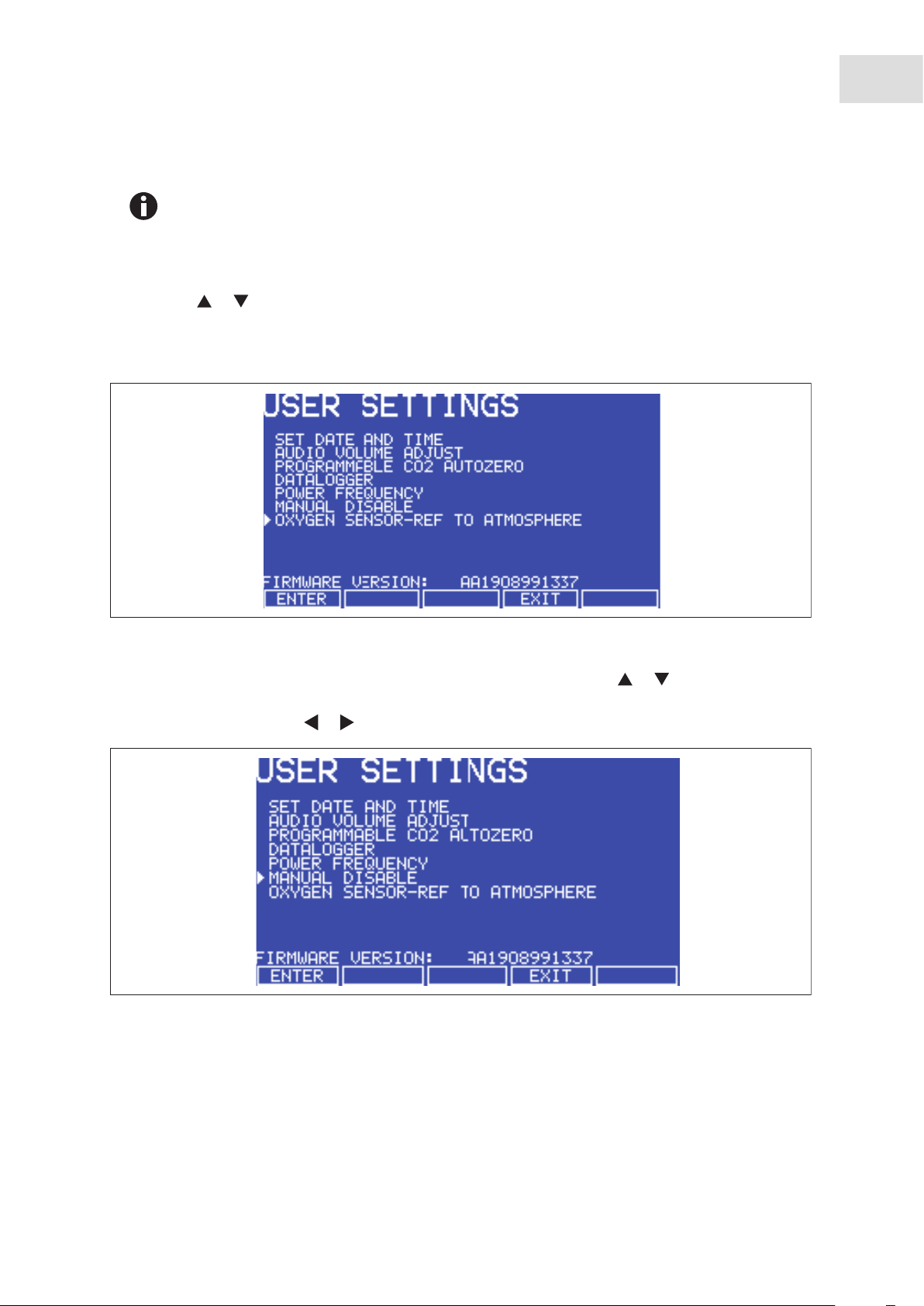
Galaxy
®
170 R/170 S CO2 Incubators
English (EN)
Equipment options
73
If the programmed O
level is close to the ambient oxygen, it may be necessary to reduce the
2
cylinder pressure below 1 bar to stop the oxygen level from undershooting the programmed
value.
Both inner and outer doors must be open.
4. After the incubator has been humidified and left overnight to stabilize, select the USER menu; then,
using the or direction key, select OXYGEN SENSOR-REF TO ATMOSPHERE (see Fig. 12-2 on
p. 73) and follow the onscreen instructions to automatically calibrate the oxygen sensor to atmospheric
oxygen levels. The oxygen reading is automatically adjusted to 19.7 %, which is the true reading taking
into account the relative humidity level.
Abb. 12-2: Selecting OXYGEN SENSOR-REF TO ATMOSPHERE
Fig. 12-2: Selecting OXYGEN SENSOR-REF TO ATMOSPHERE
5. Enable the oxygen control: (a) press the USER function key, (b) using the or direction key, select
MANUAL DISABLE (see Fig. 12-3 on p. 73), (c) press the ENTER function key, (d) select ENABLE for
Oxygen Control using the or direction key, then (e) press the ENTER function key.
Abb. 12-3: USER SETTINGS Screen
Fig. 12-3: USER SETTINGS Screen
6. Navigate to the PROG screen to set the required Oxygen level.
7. The Alarm levels are automatically set to ± 0.5 % above or below the programmed value, but you can
modify them in the ALARM screen. Re-arming the alarm can be delayed until the programmed value is
achieved: select the relevant option in the ALARM screen.
Page 74

74
Equipment options
®
Galaxy
170 R/170 S CO2 Incubators
English (EN)
At low oxygen levels, the CO
and O2 levels may not have fully recovered within the Alarm
2
limits after the 15-minute “Delay in arming after door opening.” This time period can be
increased (in the ALARM screen) to suit individual circumstances.
8. By controlling the Duty Cycle of the N2 valve, Oxygen Control can be tailored to achieve programmed
Oxygen and Carbon Dioxide levels at approximately the same time.
12.4.3 Operating guidelines
We recommend that you repeat the OXYGEN SENSOR-REF TO ATMOSPHERE procedure (see Setting up
tank on p. 72) Step 3, and further details (see Referencing to atmosphere on p. 74) once a month to
the N
2
ensure that any long-term drift in sensor output will be corrected. Be sure to do it at the chamber operating
temperature.
When you are cleaning the chamber, be very careful not to wet the oxygen sensor or CO
solvents on the sensor membrane; rather, be sure to cap the hydrophobic filter before you clean. It is good
practice to replace the filter each time you clean the incubator chamber, to avoid the possibility of filter
contamination.
Under normal relative humidity conditions (95 - 99 %), the oxygen sensor’s performance should not be
affected. If, however, liquid condenses around the sensor, gas flow may become restricted, giving the
sensor a low signal. This may occur if there is a large liquid spill inside the chamber or if the incubator is
turned off while it is fully humidified. Should such condensation appear, normal operation can be restored
by:
sensor. Never use
2
• removing the humidity tray,
• drying the chamber completely,
• and then running the incubator at 37 °C for one hour.
This will dry out the sensor(s). The humidity tray can then be reinstalled and the incubator can be safely
re-humidified.
12.4.4 Referencing to atmosphere
The oxygen sensor is a self-powered electrochemical cell that has a finite life dependent on the ambient
oxygen level. A typical lifespan is 1 - 2 years at atmospheric levels. During the sensor’s lifespan, the signal
produced will slowly degrade until it is ultimately unusable. For this reason, we recommend that you
reference the sensor to atmospheric oxygen levels on a monthly basis.
The OXYGEN SENSOR-REF TO ATMOSPHERE procedure has three possible outcomes. The first is that
the procedure was completely successful, and no further action need be taken until the following month’s
test. The second and third outcomes are presented in detail in (see Replace sensor soon on p. 75) and (see
Replace sensor now on p. 75).
For instructions on removing and replacing the sensor (see Removing and replacing O
sensor on p. 76).
2
Page 75

®
Galaxy
170 R/170 S CO2 Incubators
English (EN)
12.4.5 Replace sensor soon
If the referencing procedure was successful but the sensor is nearing the end of its working life, the
following message will appear in the display:
REFERENCE OK BUT SENSOR REQUIRES REPLACEMENT SHORTLY
O
2
PRESS ENTER TO PROCEED
When you press the ENTER function key, the message will change to this:
SENSOR
O
2
Equipment options
75
THE RESULT OF THE O
REFERENCE PROCESS SHOWS THAT THE SIGNAL FROM THE O2 SENSOR HAS
2
REDUCED INDICATING IT IS APPROACHING THE END OF ITS LIFE.
REPEAT THE REFERENCE PROCEDURE TO CONFIRM THIS RESULT.
PRESS ENTER TO PROCEED.
Press the ENTER function key.
12.4.6 Replace sensor now
If the referencing procedure failed, Oxygen Control will be disabled. The incubator will appear to be
functioning as normal until a new sensor is installed and referenced to atmospheric level. The following
message will appear in the display:
REFERENCE FAILED
O
2
PRESS ENTER TO PROCEED
When you press the ENTER function key, the message will change to this:
SENSOR
O
2
THE RESULT OF THE O
REFERENCE PROCESS SHOWS THAT THE SIGNAL FROM THE O2 SENSOR HAS
2
REDUCED BELOW AN ACCEPTABLE LEVEL AND HAS REACHED THE END OF ITS LIFE.
REPEAT THE REFERENCE PROCEDURE TO CONFIRM THIS RESULT.
PRESS NEXT TO PROCEED.
When you press the NEXT function key, the message will change to this:
SENSOR
O
2
Page 76

76
Equipment options
®
Galaxy
170 R/170 S CO2 Incubators
English (EN)
OXYGEN CONTROL HAS BEEN DISABLED AS A RESULT BUT THE INCUBATOR IS OTHERWISE FULLY
OPERATIONAL.
PRESS PREV TO VIEW PREVIOUS SCREEN. PRESS EXIT TO EXIT.
When you press the EXIT function key, you will return to the USER screen and normal operation.
12.4.7 Removing and replacing O2 sensor
Prerequisites
• Oxygen sensor removal tool (see Fig. 12-5 on p. 77)
NOTICE! Risk of material damage
Grasp white connector body when disconnection wire leads.
Do not pull on wire leads.
1. Pull the rear access cover (see Fig. 12-4 on p. 76) off the rear outside wall of the incubator to gain
access to the oxygen sensor.
Abb. 12-4: Oxygen sensor rear access cover
Fig. 12-4: Oxygen sensor rear access cover
2. Reach inside and disconnect the sensor by unplugging the connector: be sure to grasp the white
connector body.
3. Using the sensor removal tool (see Fig. 12-5 on p. 77), unscrew the oxygen sensor by turning it
counter-clockwise. Because the oxygen sensor contains lead, be sure to dispose of it according to local
regulations.
Page 77

®
Galaxy
170 R/170 S CO2 Incubators
English (EN)
Equipment options
Abb. 12-5: Oxygen sensor removal tool
Fig. 12-5: Oxygen sensor removal tool
4. Using the sensor removal tool, install the new oxygen sensor by turning it clockwise until it is
finger-tight. Do not use excessive force or any metal tool.
5. Reconnect the sensor by plugging the white connector body back in.
6. Make sure that the sensor wires are inside the metal sensor tube to protect them from damage, then
press the rear access cover snugly back in place.
7. After replacing the sensor, humidify the incubator and allow it to stabilize overnight.
8. Calibrate the sensor with reference to the atmospheric oxygen level (see Referencing to atmosphere on
p. 74).
77
12.4.8 Replacing the filter disc
The hydrophobic filter installed on your Oxygen Control system helps prevent condensation from reaching
the sensor (see Fig. 12-6 on p. 78).
12.4.8.1 To replace the hydrophobic filter disc (membrane)
1. Carefully pull the complete hydrophobic filter holder away from the oxygen sensor holder on the rear
wall of the chamber.
2. With a fingertip or a 10 - 11 mm (½ in) rod, from the rear of the filter holder, gently push the filter
membrane disc and the filter cap out of the holder.
3. Clean and dry the filter holder and cap.
4. Wearing gloves to avoid contaminating the filter disc, gently place the new filter membrane disc into the
filter holder recess. The filter disc works in both directions, so there is no right or wrong side.
Page 78

78
Equipment options
®
Galaxy
170 R/170 S CO2 Incubators
English (EN)
Abb. 12-6: Hydrophobic filter and holder assembly (exploded view)
1
23
54
Fig. 12-6: Hydrophobic filter and holder assembly (exploded view)
1 Oxygen sensor holder
2 Hydrophobic filter disc
4 Hydrophobic filter cap
5 Oxygen sensor
3 Hydrophobic filter holder
5. Make sure the O-rings (between the cap & filter holder and between the filter holder & oxygen sensor
holder) are undamaged and securely in place.
6. Gently press the filter cap back in.
7. Press fit the filter assembly back onto the oxygen sensor holder.
12.4.9 Troubleshooting the O2 sensor
If the oxygen sensor fails suddenly, it is very likely that the sensor inlet membrane has become blocked by
condensation. This can be seen on the DATALOGGER screen as a sudden drop from the programmed value
to nearly zero.
To dry the membrane:
1. Remove the hydrophobic filter holder assembly (see Fig. 12-4 on p. 76) by unscrewing it
(counter-clockwise).
2. Program the incubator for a temperature of at least 37 °C (or higher if you normally operate the
incubator at a higher temperature).
3. Close the door and allow the temperature to recover.
Page 79

®
Galaxy
170 R/170 S CO2 Incubators
English (EN)
4. Reopen the door for 15 seconds to release any build-up of humidity.
Equipment options
5. Repeat steps 3 and 4 every 30 minutes while monitoring the DATALOGGER O
Graph. The oxygen level
2
should recover after a few hours.
6. Leave the incubator for a few more hours to be ensure that the sensor membrane has thoroughly dried
out.
7. Replace the hydrophobic filter disc (see Replacing the filter disc on p. 77).
8. Re-humidify the incubator.
9. After 2 to 3 hours, carry out an OXYGEN SENSOR-REF TO ATMOSPHERE (see Referencing to
atmosphere on p. 74). When the referencing has been successfully completed, the incubator is ready for
use.
12.4.10 Specifications
The Oxygen Control option has the following characteristics:
79
Sensor Type Self-powered, diffusion-limited, electrochemical cell with temperature
compensation.
Zero Signal in Nitrogen < 50 μV
Temperature Compensation ± 2 % of signal variation from 0 - 40 °C
Relative Humidity Range 0 - 99 %, non-condensing
Operating Temperature Range -20 °C to + 50 °C
Resolution 0.01 % Oxygen
Expected Operating Life 1 - 2 years in ambient oxygen
Hydrophobic Filter Operating
Life
No data available on the filter lifespan but we are confident to expect it
will last at least 6 months.
Nitrogen Input Rate 20 L/min at 14.5 PSI (1 bar)
Typical Oxygen Reduction Rates 3 minutes to 16 %
4 minutes to 11 %
8 minutes to 6 %
Page 80

80
Equipment options
®
Galaxy
170 R/170 S CO2 Incubators
English (EN)
12.5 O2 control (0.1 - 19 %) (Galaxy R only)
This oxygen control option uses the controlled addition of nitrogen to reduce the oxygen level below
ambient. If you have the 1 - 19 % oxygen control option, (see O
p. 72); or if you have the 1 - 95 % oxygen control option, (see O
p. 83).
sensor must be calibrated when used to achieve O2 control below 1 %. For calibration
The O
2
instructions, refer to M1306-0051, Galaxy
®
O2 Sensor Setup Instructions manual.
You will need an oxygen sensor zeroing kit to perform the calibration. Contact Eppendorf
sales for ordering information.
12.5.1 Setting up the N2 tank
Prerequisites
Before you set up your oxygen control, ensure that you have the proper equipment for your nitrogen
supply:
control (1 - 19 %) (Galaxy R only) on
2
control (1 - 95 %) (Galaxy R only) on
2
• 2 cylinders of nitrogen, regulation size W
• 1 two-stage pressure regulator
• 1 Inline pressure regulator
• 6 mm PVC tubing
• tubing clips
Set up the nitrogen tanks as follows:
1. Inspect them to ensure there are no leaks or other damage.
2. Check that the two-stage pressure regulator valve and the inline pressure regulator valve are closed by
trying to turn their knobs in a counter-clockwise direction; the knobs should be at the stop point.
3. Place the inline pressure regulator close to the incubator.
4. Securely attach the two-stage pressure regulator to the nitrogen tank’s outlet and to the inline pressure
regulator’s inlet with tubing, securing both ends with clips.
5. Connect the inline pressure regulator’s outlet to the incubator’s N
inlet on the right side of the control
2
box at the rear of the incubator (see Fig. 2-3 on p. 11); secure both ends with clips.
6. Proceed as indicated in (see Setting up O
control on p. 80).
2
To add an automatic gas cylinder changeover instrument: with the incubator turned off,
connect its inlet to the two-stage pressure regulator’s outlet, and the changeover instrument’s
outlet to the inline pressure regulator’s inlet with tubing, securing the ends with tubing clips.
12.5.2 Setting up O2 control
Oxygen control is tailored such that both the O2 and the CO2 levels are achieved at approximately the same
time, via control of the N
valve’s duty cycle (but only within the range of 0.1 - 19 % O2).
2
Page 81

®
Galaxy
170 R/170 S CO2 Incubators
English (EN)
1. Remove the black plastic protective cover (making sure that the hydrophobic filter cap is not removed
with it) from the port inside the chamber. Retain the cover for use when you clean the chamber.
Equipment options
2. Open the nitrogen gas supply from the tank and set the N
tank’s outlet pressure gauge to 1.5 bar.
2
3. Set the nitrogen regulator to 14.5 PSI (1 bar). The nitrogen will be fed into the incubator through a filter
that is already installed in the gas line. The gas flow rate is approximately 20 liters/minute.
81
• If the programmed O
level is close to the ambient oxygen, it may be necessary to reduce
2
the cylinder pressure below 1 bar to stop the oxygen level from undershooting the
programmed value.
• When working at 0.1% O
, set the CO2 pressure to 10 PSI (0.7 bar).
2
Be sure to humidify the incubator and leave it overnight to stabilize before proceeding further.
To automatically calibrate the sensor to atmospheric oxygen levels, select OXYGEN SENSOR – REF TO
ATMOSPHERE in the USER menu, and then follow the onscreen instructions.
The oxygen reading is automatically adjusted to 19.7 %, which is the true reading taking into account the
Relative Humidity in the chamber.
12.5.3 Enabling or disabling O2 control
To enable oxygen control:
1. Select the USER screen by pressing the USER function key.
2. Use the direction keys to select MANUAL DISABLE.
3. Press the ENTER function key, then use the direction keys to select ON for Oxygen Control.
4. Press the ENTER function key again.
Program the required oxygen level in the PROG screen, following the onscreen instructions.
To disable oxygen control, follow the pattern used to enable it, but this time select USER, MANUAL
DISABLE, ENTER, OFF and then ENTER again.
12.5.4 Alarms
The alarm levels are set automatically to ± 0.5 % above and below the programmed value, but these points
can be altered in the ALARM screen. In addition, the re-arming of the alarm can be delayed until the
Programmed Value is achieved by selecting the relevant option in the ALARM screen.
For example, it is possible at low oxygen levels that the CO
and O2 levels might not fully recover within the
2
Alarm Limits after the 15-minute DELAY IN ARMING AFTER DOOR OPENING period has elapsed, so this
time period can be increased in the ALARM screen to suit individual circumstances.
12.5.5 Referencing to atmosphere
To reference the oxygen sensor to atmospheric oxygen levels, (see Referencing to atmosphere on p. 74).
Page 82

82
Equipment options
®
Galaxy
170 R/170 S CO2 Incubators
English (EN)
12.5.6 Programming desired O2 level
Program the required oxygen level in the PROG screen, following the onscreen instructions.
If you are running an O
is set to operate in the following way to minimize N
• The N
• The CO
valve is switched on continuously until the O2 level is within 0.1 % of setpoint.
2
valve is then switched on to allow the CO2 level to reach setpoint. If the O2 level is above
2
setpoint 15 minutes after the N
the CO
valve is switched on for 20 seconds. The CO2 valve will then pulse until setpoint is reached.
2
• The process described above will repeat itself until the O
• The same process will also repeat if the O
level programmed between 0.1 - 0.9 %, you should know that the control system
2
consumption after the glass door has been opened:
2
valve has been switched off, it is switched back on for 40 seconds and
2
setpoint is reached.
2
level rises above setpoint, and if the O2 level should rise
2
toward 0.2 % above setpoint, the N2 valve will open again continuously until the O2 level returns to
setpoint.
• The CO
introduction of additional O
programmed CO
Auto-Zero, which would normally take place after a CO2 alarm, will be cancelled to avoid the
2
into the chamber. For the same reason, we recommend canceling the
2
Auto-Zero.
2
12.5.7 Precautions
Under normal humidity conditions (95 - 99 % RH), the sensor is unaffected. If for any reason (such as a
large spill inside the chamber or the incubator being switched off while fully humidified) liquid condenses
around the sensor, the result may be restriction of gas flow and a low sensor signal. Should such
condensation appear on the chamber walls, normal operation can be easily restored by removing the
humidity tray, drying the chamber completely, and then running the incubator at 37 °C for one hour. This
will dry out the sensor. After the hour has elapsed, the humidity tray can be reinstalled and the incubator
humidified again.
Page 83
®
Galaxy
170 R/170 S CO2 Incubators
English (EN)
12.6 O2 control (1 - 95 %) (Galaxy R only)
This oxygen control option uses the controlled addition of oxygen to increase the level above ambient and
the controlled addition of nitrogen to reduce the oxygen level below ambient. If you have the 1 - 19 %
Equipment options
oxygen control option, (see O
control option, (see O
control (0.1 - 19 %) (Galaxy R only) on p. 80).
2
WARNING! Risk of personal injury
High oxygen levels inside the chamber require additional safety precautions:
Setting the oxygen to levels > 24 % can greatly increase the chance of fire and explosion.
Operators planning to set oxygen at 24 - 95 % should therefore take all appropriate
precautions to minimize the risk. Eppendorf does not recommend using external
(heat-generating) equipment inside the chamber when oxygen conditions will be > 24 %.
Before opening the incubator door, make sure no flames (Bunsen burner, etc.) are in the
vicinity.
Avoid the presence of other combustible gases (hydrogen, methane, etc.)
Ensure that all solenoid valves and pressure regulators and gauges controlling the gas
supply are grease-free for use with oxygen.
control (1 - 19 %) (Galaxy R only) on p. 72); or for the 0.1 - 19 % oxygen
2
83
If your incubator is operating in the 3 - 95 % range of O2 control, only the N2 valve will operate for
setpoints below 19 %; both the N
setpoints above 80 %, only the O
If you plan to maintain O
and O2 valves will operate for setpoints between 19 and 80 %; and for
2
valve will operate.
2
levels of 80 - 95 %, (see Important notes for O2 levels > 80 % on
2
p. 85).
12.6.1 Setting up the N2 tank
Prerequisites
Before you set up your oxygen control, ensure that you have the proper equipment for your nitrogen
supply:
• 2 cylinders of nitrogen, regulation size W
• 1 two-stage pressure regulator
• 1 Inline pressure regulator
• 6 mm PVC tubing
• tubing clips
Set up the nitrogen tanks as follows:
1. Inspect them to ensure there are no leaks or other damage.
2. Check that the two-stage pressure regulator valve and the inline pressure regulator valve are closed by
trying to turn their knobs in a counter-clockwise direction; the knobs should be at the stop point.
3. Place the inline pressure regulator close to the incubator.
Page 84

84
Equipment options
®
Galaxy
170 R/170 S CO2 Incubators
English (EN)
4. Securely attach the two-stage pressure regulator to the nitrogen tank’s outlet and to the inline pressure
regulator’s inlet with tubing, securing both ends with clips.
5. Connect the inline pressure regulator’s outlet to the incubator’s N
inlet on the right side of the control
2
box at the rear of the incubator (see Fig. 2-3 on p. 11); secure both ends with clips.
6. Proceed as indicated in (see Setting up O
control on p. 84).
2
To add an automatic gas cylinder changeover instrument: with the incubator turned off,
connect its inlet to the two-stage pressure regulator’s outlet, and the changeover instrument’s
outlet to the inline pressure regulator’s inlet with tubing, securing the ends with tubing clips.
12.6.2 Setting up O2 control
Oxygen control is tailored such that both the O2 and the CO2 levels are achieved at approximately the same
time, via control of the O
1. Remove the black plastic protective cover (making sure that the hydrophobic filter cap is not removed
with it) from the port inside the chamber. Retain the cover for use when you clean the chamber.
2. Open the nitrogen gas supply from the tank and set the N
3. Set the nitrogen regulator to 14.5 PSI (1 bar). The nitrogen will be fed into the incubator through a filter
that is already installed in the gas line. The gas flow rate is approximately 20 liters/minute.
or N2 valve’s duty cycle.
2
tank’s outlet pressure gauge to 1.5 bar.
2
If the programmed O
level is close to the ambient oxygen, it may be necessary to reduce the
2
cylinder pressure below 1 bar to stop the oxygen level from undershooting the programmed
value.
4. Install the oxygen cylinder in the same manner as outlined for the nitrogen cylinder installation (see
Setting up the N
tank on p. 83), using the incubator’s O2 inlet, of course. For this application, you will
2
need another two-stage pressure regulator and another inline pressure regulator.
Be sure to humidify the incubator and leave it overnight to stabilize before proceeding further.
To automatically calibrate the sensor to atmospheric oxygen levels, select OXYGEN SENSOR – REF TO
ATMOSPHERE in the USER menu, and then follow the onscreen instructions.
The oxygen reading is automatically adjusted to 19.7 %, which is the true reading taking into account the
Relative Humidity in the chamber.
12.6.3 Enabling or disabling O2 control
To enable oxygen control:
1. Select the USER screen by pressing the USER function key.
2. Use the direction keys to select MANUAL DISABLE.
3. Press the ENTER function key, then use the direction keys to select ON for Oxygen Control.
4. Press the ENTER function key again.
Program the required oxygen level in the PROG screen, following the onscreen instructions.
Page 85

®
Galaxy
170 R/170 S CO2 Incubators
English (EN)
To disable oxygen control, follow the pattern used to enable it, but this time select USER, MANUAL
DISABLE, ENTER, OFF and then ENTER again.
12.6.4 Important notes for O2 levels > 80 %
If you are running the incubator with a dry chamber and no CO2, the recommended maximum O2 level is 95
Equipment options
%. In addition, open samples inside the chamber can cause RH to increase, and the O
recalibration to work properly in a completely dry atmosphere.
sensor may require
2
85
For a humidified chamber with no CO
humidified chamber with 5 % CO
, the recommended maximum O2 level is 92 %, while for a
2
, we recommend no more than 87 % O2.
2
When the incubator is running at normal humidity level (i.e., 95 % RH), there is approximately 6 % (by
volume) water vapor present in the chamber. If 5 % CO
O
—without using excessive quantities of oxygen—is approximately 87 %. Oxygen direct from a cylinder
2
is also present, the maximum achievable level of
2
has a dewpoint temperature of < -45°C, corresponding to 0.06 % water vapor. As it enters the incubator,
therefore, its temperature is very low and even as it is warmed, its RH level is very low. Both of these factors
affect the performance of the O
detector. To minimize these effects, O2 is fed continuously until it arrives
2
at 0.4 % below setpoint. To allow the detector signal to recover and the RH level to build, there is a
3-minute delay. If O
is still required, it is fed in for 10 seconds, with an additional 3-minute delay until
2
setpoint is achieved.
As the humidity level rises, the O
as the setpoint approaches the sum contents of water vapor and CO
possible to achieve higher levels of O
continuous demand for O
and RH will remain too low. At the same time, as O2 is pumped in, the CO2 level
2
will also diminish, causing the system to add CO
If the O
setpoint is too high, the incubator can consume some 2,500 liters of O2 per day—which does not
2
content in the chamber will diminish. The use of O2 will rise considerably
2
in the chamber. In the short term, it is
2
, but as humidity rises and O2 content is pushed down, there will be a
2
, which in turn causes the O2 level to drop again.
2
include the extra oxygen consumed each time the door is opened (about 500 liters).
12.6.5 Alarms
The alarm levels are set automatically to ± 0.5 % above and below the programmed value, but these points
can be altered in the ALARM screen. In addition, the re-arming of the alarm can be delayed until the
Programmed Value is achieved by selecting the relevant option in the ALARM screen.
For example, it is possible at low oxygen levels that the CO
and O2 levels might not fully recover within the
2
Alarm Limits after the 15-minute DELAY IN ARMING AFTER DOOR OPENING period has elapsed, so this
time period can be increased in the ALARM screen to suit individual circumstances.
12.6.6 Referencing to atmosphere
It is highly recommended to reference the sensor to atmospheric oxygen at least once per
month.
Page 86

86
Equipment options
®
Galaxy
English (EN)
To reference the oxygen sensor to atmospheric oxygen levels, (see Referencing to atmosphere on p. 74).
170 R/170 S CO2 Incubators
12.6.7 Programming desired O2 level
Program the required oxygen level in the PROG screen, following the onscreen instructions.
12.6.8 Other precautions
Under normal humidity conditions (95 - 99 % RH), the sensor is unaffected. If for any reason (such as a
large spill inside the chamber or the incubator being switched off while fully humidified) liquid condenses
around the sensor, the result may be restriction of gas flow and a low sensor signal. Should such
condensation appear on the chamber walls, normal operation can be easily restored by removing the
humidity tray, drying the chamber completely, and then running the incubator at 37 °C for one hour. This
will dry out the sensor. After the hour has elapsed, the humidity tray can be reinstalled and the incubator
humidified again.
For routine service checks of the sensor, (see Troubleshooting the O
sensor on p. 78).
2
12.6.9 Specifications
(see Specifications on p. 79).
12.7 O2 Sensor replacement (Galaxy R only)
When the O2 sensor needs to be replaced, (see Removing and replacing O2 sensor on p. 76), or the Galaxy 02
Sensor Setup, M1308-0051 manual for instructions.
12.8 IP66 sealed electrical outlet socket
The IP66 Sealed Electrical Outlet Socket is designed to provide a safe and convenient means of using
electrically powered equipment within the incubator chamber. The IP66 socket is powered on a completely
separate circuit and therefore has its own plug, lead and fuse.
NOTICE! Risk of material damage
Both the incubator and the IP66 enclosure must be plugged into an electrical supply
protected by an RCD device. Any device chosen must be a “self-resetting” type which will
automatically reconnect power to the incubator as soon as power is restored after a power
failure.
The socket (see Fig. 12-8 on p. 89) is located on the back wall of the chamber, on the right-hand side
between the second and third shelf. The socket is powered by an independent power inlet located above
the control box at the rear of the incubator (see Fig. 12-7 on p. 87). The socket also has an independent
Page 87
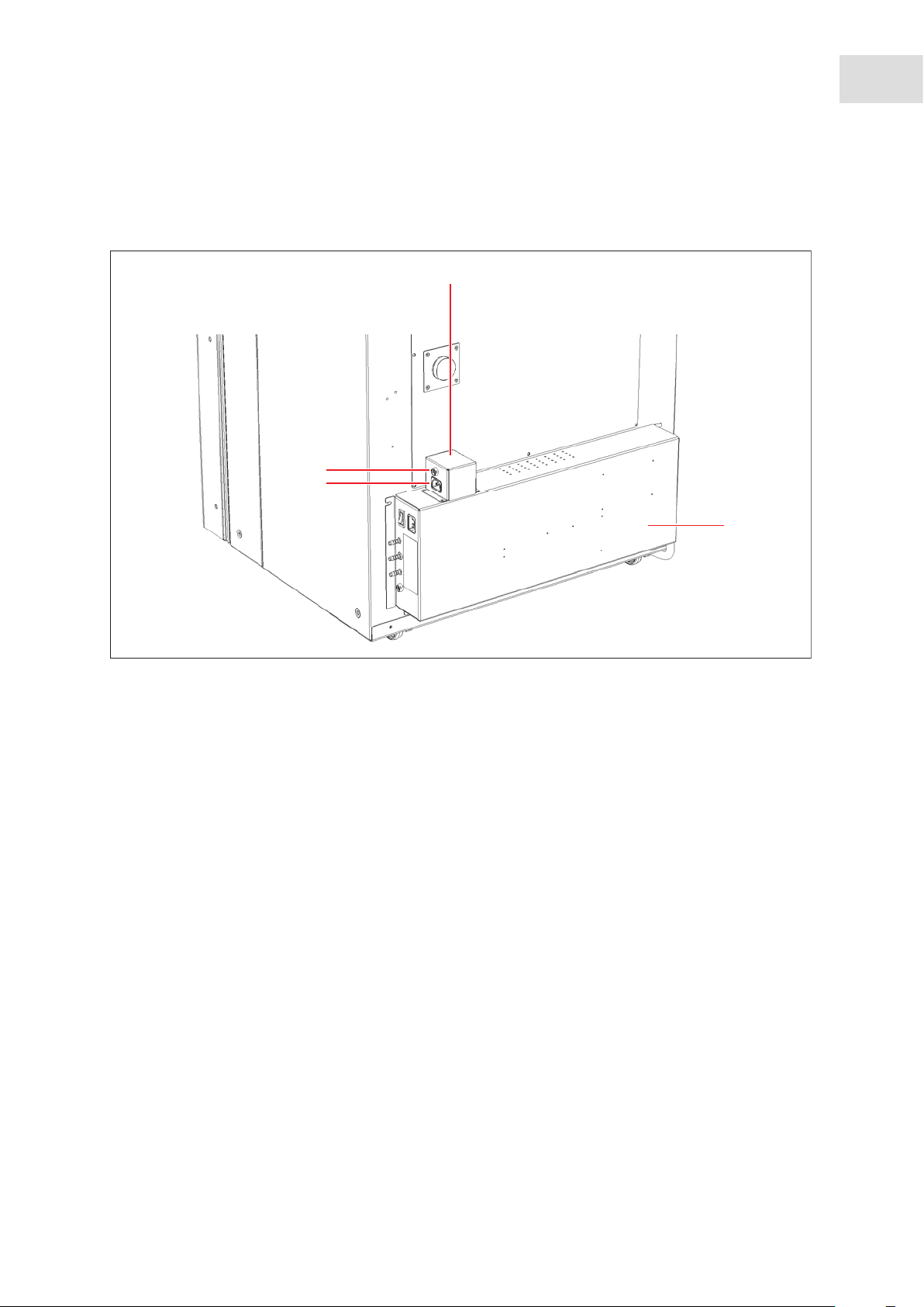
®
Galaxy
170 R/170 S CO2 Incubators
English (EN)
fuse which is rated at 4 Amps. There is a dedicated switch for this socket, illuminated green when it is on;
the switch is located on the left front of the incubator.
Equipment options
Abb. 12-7: IP66 Enclosure
1
4
3
87
Fig. 12-7: IP66 Enclosure
1 IP66 enclosure
2 Control box
2
3 IP66 power inlet
4 IP66 fuse holder
Page 88
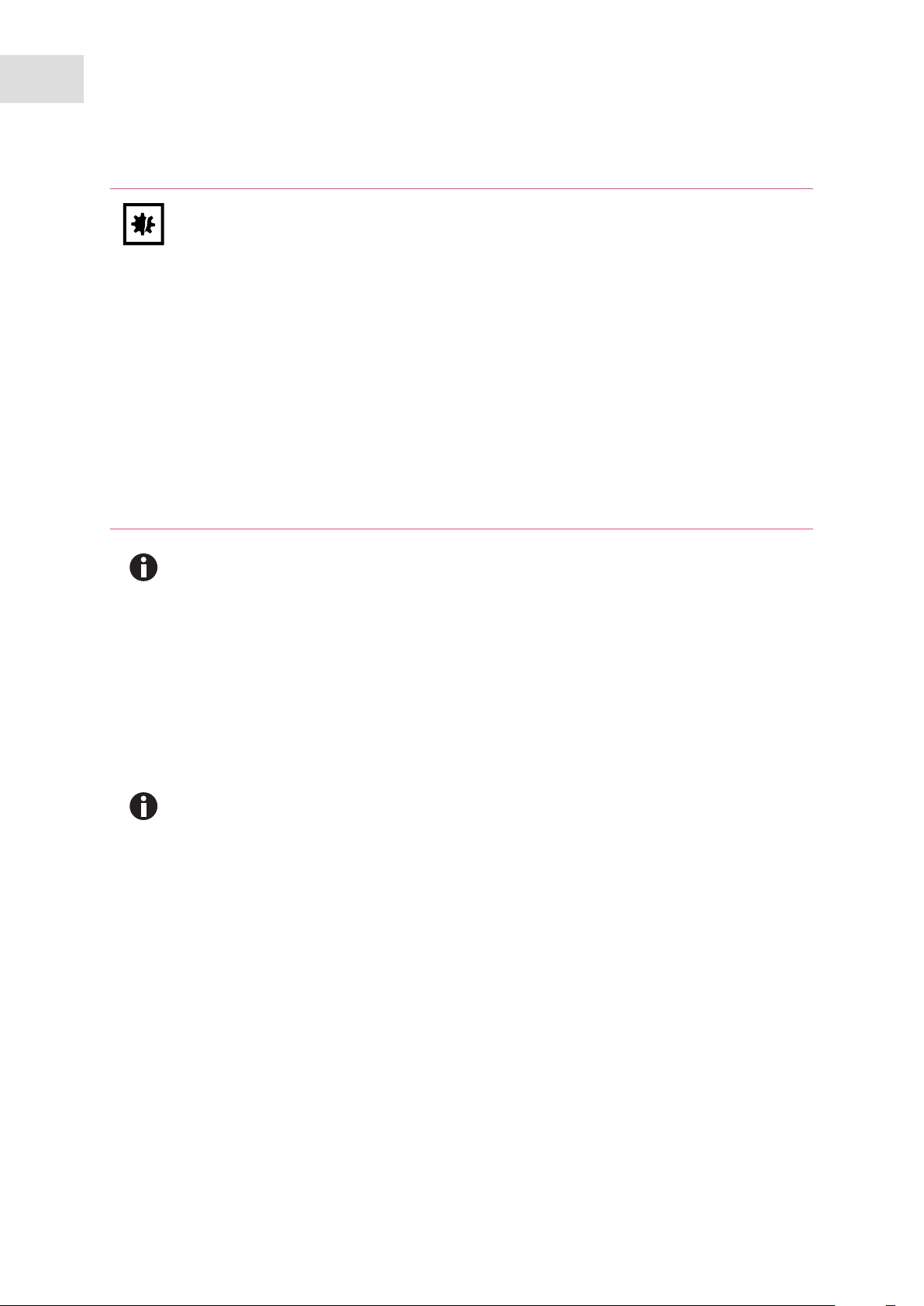
88
Equipment options
®
Galaxy
English (EN)
170 R/170 S CO2 Incubators
NOTICE! Risk of material damage
Working with electrical power inside a humid environment (where the incubator is
humidified) can cause damage. The following precautions should be observed:
The instrument or equipment, and its external connections, to be used inside the chamber
should be specified as suitable for use in a humid environment, and at 37 °C (see also
“Using Powered Equipment within the Chamber”). If in doubt, consult with the
manufacturer of the equipment.
Always ensure the connections are properly and securely made.
Be sure to switch OFF the green illuminated switch on the front left of the incubator before
connecting or disconnecting equipment inside the chamber, if equipped with optional IP66
socket.
The Sealing Cap must always be in place when the socket is not in use.
Both the incubator and the IP66 enclosure must be plugged into an electrical supply
protected by an RCD device. Any device chosen must be a self-resetting type which will
automatically reconnect power to the incubator as soon as power is restored following a
power failure.
If the incubator is to be used humidified, the normal RH level is ~ 95 %, so any electrically
powered equipment or device to be used inside the chamber must be designed for use in a
humid atmosphere. Consult the manufacturer of the equipment to ensure that it is suitable.
To minimize the thermal gradient within the chamber, the instrument you place inside the chamber should
be placed on the bottom shelf. The heat dissipated by the equipment should be as low as possible to
minimize thermal disturbance to the chamber. Some shakers, stirrers etc., have been specifically designed
to give a low heat output for use in incubators. The maximum heat that can be dissipated within the
chamber is variable, depending on the difference between the ambient and programmed temperatures. If
the heat dissipated is too great, the chamber will tend to overheat. If this happens, the control parameters
can be adjusted to compensate.
Any heat-generating equipment used inside the chamber will naturally affect the temperature
performance of the incubator. For this reason, if you plan to use equipment which may
generate heat in the chamber, we recommend equipping the incubator with the optional
cooling system (see Cooling system on p. 65).
To connect to the socket (see Fig. 12-8 on p. 89) inside the chamber, a power cable with a matching IP66
plug is supplied. This power cable should be fitted by a qualified person to the equipment or device to be
used inside the chamber. If the cable cannot be fitted, contact your distributor, giving details of the
connectors required, so they can supply a suitable lead.
Page 89

Abb. 12-8: IP66 Socket
®
Galaxy
170 R/170 S CO2 Incubators
English (EN)
NOTICE! Risk of material damage
The Electrical Socket and the matching plug are both sealed to IP66 and are capable of
being heated to 120 °C during the High Temperature Disinfection cycle, but the electrical
cable is NOT rated for use at 120 °C. Therefore, the equipment or device and the
connecting cable must be removed from the chamber, and the Sealing Cap replaced on the
socket prior to starting a High Temperature Disinfection cycle.
1
42
Equipment options
89
3
Fig. 12-8: IP66 Socket
1 Live
2 Not used
3 Ground
4 Neutral
12.9 Humidity alert and monitoring package (Galaxy R only)
The humidity alert package includes a humidity tray warning system and humidity display and alarm
function, both providing optimal feedback on relative humidity inside the incubator chamber.
12.9.1 Humidity tray warning system
The humidity tray warning system is designed to prevent the water level in the humidity reservoir from
becoming too low. The water level is continuously measured by an optical water level sensor. If the water
level in the humidity tray become too low a “Humidity Water Low Alarm” is displayed. This alarm can be
cancelled by pressing any key, but it will re-activate when the glass door is opened and closed.
The humidity alarm system can be deactivated as follows:
Humidity Tray Warning System with High Temperature Decontamination Option (Galaxy R
model only).
Page 90

90
Equipment options
®
Galaxy
170 R/170 S CO2 Incubators
English (EN)
NOTICE! Risk of damage to equipment
The bottom surface of the incubator is heated to over 150 °C during the decontamination
cycle which may affect the sensor or the cable if left in contact with the bottom of the
incubator.
Never leave the humidity warning sensor on the bottom surface of the incubator during a
high temperature decontamination cycle. Place it on the shelf above the humidity tray and
ensure that the cable is not resting on the base of the incubator chamber.
1. Press USER.
2. Select DISABLE and toggle HUMIDITY WARNING from ON to OFF using the keys.
3. Press ENTER.
4. Refill the humidity tray with 1.5 liters of warm (~37.0 °C) distilled water.
When the water level has been replenished and the door is closed the system will re-arm.
12.9.2 Humidity display and alarm system
The Humidity Display and Alarm System is designed to measure the relative humidity level (rH) in the
chamber and to display the chamber rH on the display screen. Under normal operating conditions and
using the supplied humidity tray, the rH level will reach a maximum of 95 - 96 % after being left overnight.
The Humidity Sensor will activate an alarm if relative humidity falls below the preset limit of 88 %. The
sensor is located on the rear wall of the chamber, below the CO
active, but the Alarm System can be deactivated as follows:
1. Press USER.
2. Select DISABLE, and toggle RELATIVE HUMIDITY from ON to OFF using the keys.
3. Press ENTER.
The Alarm System is disarmed for 1 hour or when it achieves 88% R/H, when the incubator is switched on,
or if the door is opened and closed.
An Alarm is signaled by a flashing RH LOW ALARM message. If the humidity level rises above 88 % during
the 1 hour time out period, the Humidity Alarm System will be armed. The Alarm will then be triggered
when the R/H level falls below 88 % and will be recorded by the Alarm Log. The Alarm can be
acknowledged by pressing any key. No further Alarms will occur unless the door is opened and closed, or
power to the incubator is removed then restored.
The Humidity Sensor is protected by a white porous plastic cover, care must be taken not to
spill any liquid into the sensor. The white porous cover should be protected with the black
plastic sleeve provided when cleaning the incubator. The white porous cover can be removed
and autoclaved but care should be taken not to touch or wet the sensor when the cover is
removed.
Sensor. The Humidity Display is always
2
Page 91

Equipment options
English (EN)
Galaxy
®
170 R/170 S CO2 Incubators
12.10 Copper inner chamber
Copper naturally changes color. This incubator had a bright finish when it was manufactured. The dull
finish that you see is a result of oxidation of the copper surface: it is the properties of this oxidation that
create the important anti-microbial surface.
91
Page 92

92
Equipment options
®
Galaxy
170 R/170 S CO2 Incubators
English (EN)
Page 93

Stacking stand installation
®
Galaxy
170 R/170 S CO2 Incubators
English (EN)
13 Stacking stand installation
13.1 Intended use
The stacking stand is designed for two Galaxy 170 incubators to be stacked on top of each other. The stand
can also be used to stack two Galaxy Plus series (not available in North America) incubators or any
combination of a Galaxy Plus model with a Galaxy 170. For optimum stability, if a 170 incubator is being
stacked with another Galaxy model, the 170 should be on the bottom.
13.2 Warnings for intended use
Before using the stacking stand, read this entire section and observe the following general safety
instructions.
WARNING! Personnel injury and equipment damage!
93
Great care should be taken when moving the stacked incubators. Hazards, including
uneven surfaces and obstructions, may cause the stacked assembly to topple, potentially
injuring personnel.
CAUTION! Personnel injury and equipment damage!
Four people are required to safely lift a Galaxy 170 incubator.
When lifting, be sure to use the lifting handles provided with the incubator.
NEVER lift the incubator by the door as this may cause damage.
13.3 General description
The stacking stand is designed for two Galaxy 170 incubators to be stacked on top of each other. The stand
can also be used to stack two Galaxy Plus series (not available in North America) incubators or any
combination of a Galaxy Plus model with a Galaxy 170. For optimum stability, if a 170 incubator is being
stacked with another Galaxy model, the 170 should be on the bottom. There is a lower and upper stacking
frame kit available.
13.3.1 Ordering options
The following Table lists the options available for the stacking stand when ordering. Contact Eppendorf
sales for ordering information.
Description
Lower and Upper Stacking Frame Kit
Upper Stacking Frame only
Lower Stacking Frame only
Page 94

94
Stacking stand installation
®
Galaxy
English (EN)
Kit for Stacking a pre-2000 incubator onto a Galaxy 170
170 R/170 S CO2 Incubators
13.3.2 Stacking frame kit contents
All of the parts listed for both kits below are included in the Lower and Upper Stacking Frame Kit
(P0628-6270). Check that you have received all of the parts appropriate to the kit you ordered:
Upper Stacking Frame contents: See the Table below.
Quantity Part Description
1 Upper stacking plate with foam insulation
4 M6 x 50 mm slotted pan head bolts
4 Foot locking brackets
4 M6 x 12 mm cap head Allen bolts
1 Allen wrench set
2 Incubator feet with M8 nuts
4 Pads for incubator feet
Lower Stacking Frame contents: See the Table below.
Quantity Part Description
1 Lower stacking frame
2 Swivel castors, each with adjustable stabilizing foot
2 Fixed castors
8 M8 x 20 mm button head bolts with washers (to mount fixed castors)
2 Incubator feet with M8 nuts
4 Pads for incubator feet
1 Wrench to attach castors
1 Allen wrench set
13.4 Instructions for stacking incubators
WARNING! Personnel injury and equipment damage!
Great care should be taken when moving the stacked incubators. Hazards, including
uneven surfaces and obstructions, may cause the stacked assembly to topple, potentially
injuring personnel.
Page 95

Stacking stand installation
®
Galaxy
170 R/170 S CO2 Incubators
English (EN)
CAUTION! Personnel injury and equipment damage!
Four people are required to safely lift a Galaxy 170 incubator.
When lifting, be sure to use the lifting handles provided with the incubator.
NEVER lift the incubator by the door as this may cause damage.
1. At least two persons are needed to very carefully tip the first incubator forward on its front feet, until the
rear castors are accessible. Hold the incubator steady.
CAUTION! Equipment Damage!
The illustration below is for reference only. Never turn the incubator upside down.
A third person should be used to remove the rear castors in the next step.
2. Utilizing a third person and using a flat-bladed screwdriver, remove the rear castors from the bottom of
the incubator.
Abb. 13-1: Castor Removal
95
Fig. 13-1: Castor Removal
3. In place of the castors, fit the feet to the rear of the incubator (see the Figure below).
Page 96

96
Stacking stand installation
®
Galaxy
170 R/170 S CO2 Incubators
English (EN)
Abb. 13-2: Feet Installation
Fig. 13-2: Feet Installation
4. Adjust the height of the feet to ensure that the incubator is level.
The feet on the bottom incubator should ideally be set at a height of 32mm, and the feet on the
top incubator at 32mm.
5. Repeat steps 1-4 for the second incubator.
6. Using the wrench provided, fit the adjustable castors to the front underside of the lower stacking frame
(see Figure below).
Abb. 13-3: Lower Stacking Frame Castor Installation
Fig. 13-3: Lower Stacking Frame Castor Installation
1 Wrench 2 Castor
Page 97

Stacking stand installation
®
Galaxy
170 R/170 S CO2 Incubators
English (EN)
7. Using the appropriate Allen wrench in the set provided, install the fixed castors to the rear underside of
the lower stacking frame using the M8 button head bolts (see Figure below).
Abb. 13-4: Castor Bolts
97
Fig. 13-4: Castor Bolts
8. Turn the lower stacking frame over, ensuring that it is on a flat surface.
Page 98
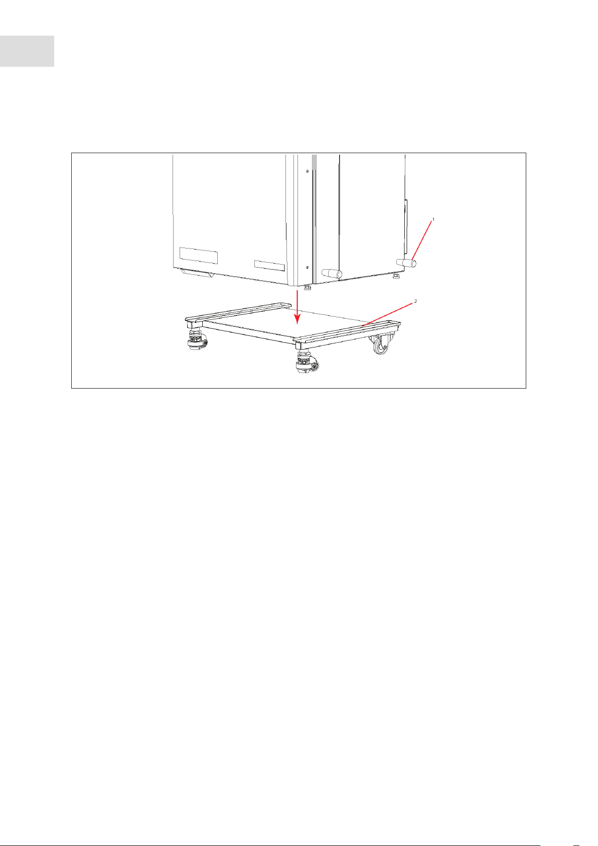
98
Stacking stand installation
®
Galaxy
170 R/170 S CO2 Incubators
English (EN)
9. With four people, each using one of the lifting handles, lift the bottom incubator onto the stand, placing
the incubator feet into the stand’s guiderails (see Figure below).
Abb. 13-5: Lifting Handles And Guides For Incubator Feet
Fig. 13-5: Lifting Handles And Guides For Incubator Feet
1 Incubator Lifting Handles 2 Guides For Incubator Feet
10.Using a flat-bladed screwdriver, adjust the front castors until their rubber feet contact the floor (see
Figure below).
Page 99
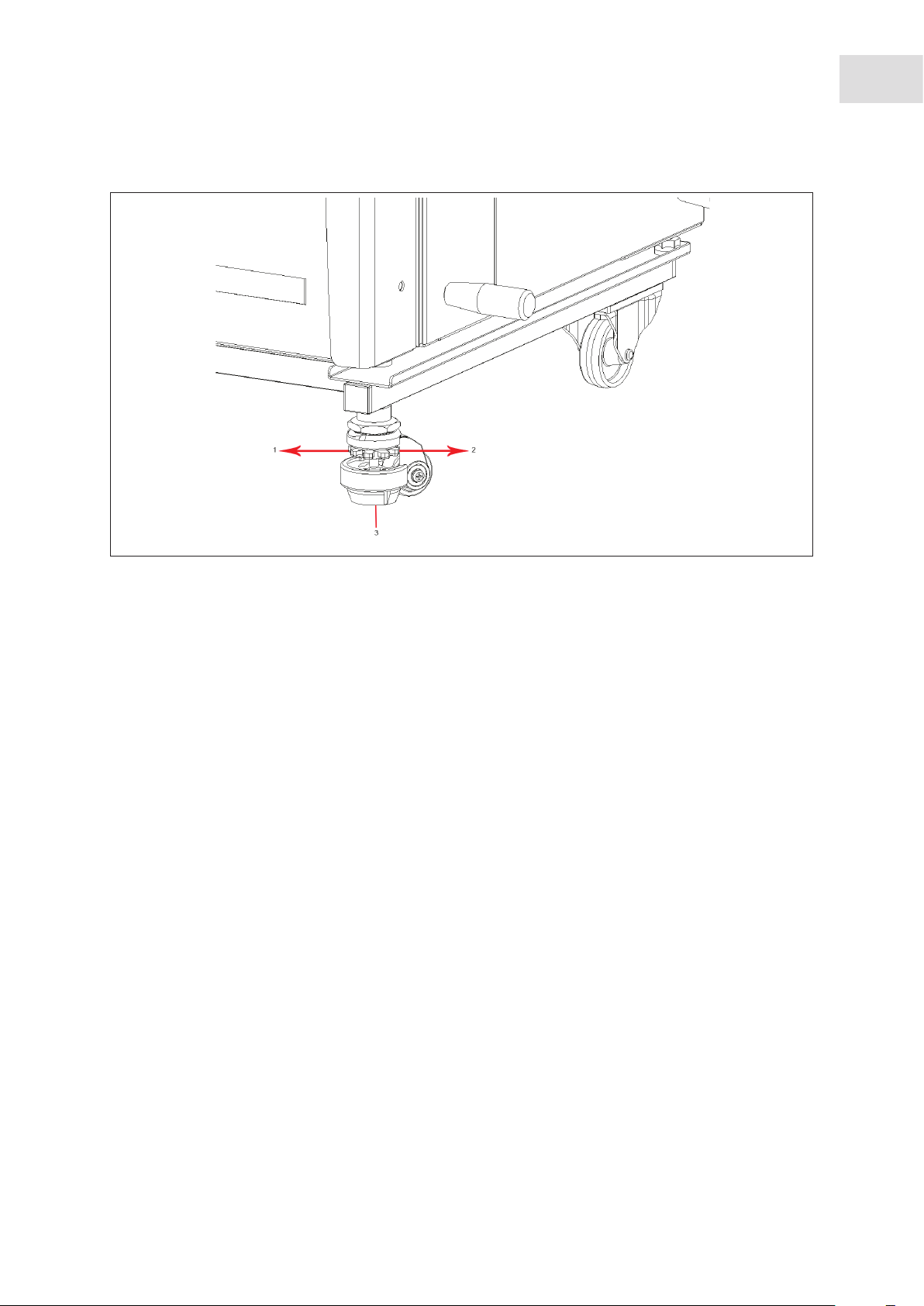
Abb. 13-6: Leveling Foot Adjustment
Galaxy
Stacking stand installation
®
170 R/170 S CO2 Incubators
English (EN)
99
Fig. 13-6: Leveling Foot Adjustment
1 Turn red adjuster in this direction to move foot
3 Rubber Leveling Foot
up.
2 Turn red adjuster in this direction to move foot
down.
11.Remove the thread covers from the top of the incubator (in the locations shown below), then, using a
flat-bladed screwdriver, attach the upper stacking frame to the top of the bottom incubator using the M6
x 50mm bolts provided.
Page 100

100
Stacking stand installation
®
Galaxy
170 R/170 S CO2 Incubators
English (EN)
Abb. 13-7: Upper Stacking Frame Installation
Fig. 13-7: Upper Stacking Frame Installation
12.With four people, each using one of the lifting handles, lift the top incubator onto the upper stacking
frame, making sure to place a pad under each foot. Fit the incubator feet into the dimples on the upper
stacking frame (see Figure below).
Abb. 13-8: Incubator Into The Upper Stacking Frame
Fig. 13-8: Incubator Into The Upper Stacking Frame
 Loading...