

Page 1
656 Actuator
D100086X012
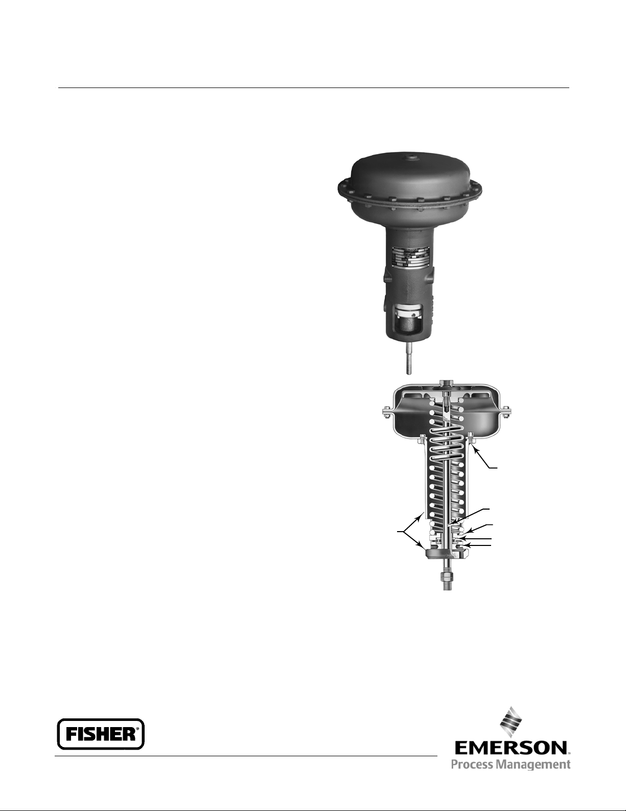
Fisherr 656 Diaphragm Actuator
The Fisher 656 actuator is a bracket-mounted,
direct-acting, diaphragm actuator for either throttling
or on-off service. Principal applications include
operation of butterfly valves and built-in turbine
valves, louvers, dampers, and other similar equipment.
Features
Mounting Versatility–Four tapped holes in the
actuator base permit either bracket or plate
mounting.
Product Bulletin
61.1:656
February 2013
Long Actuator Travel–Deep casings provide up to
105 mm (4.125 inches) of maximum travel with a
size 60 actuator.
Application Versatility–Wide spring selection is
available for nearly any control application. Spring
selection procedures are quick and accurate.
Severe Service Capability–Rugged yoke and casings
provide stability and corrosion resistant protection.
Installation
The actuator may be installed in any position.
Dimensions are shown in figure 1.
W1996-2
YOKE
W0454-1
TRAVEL STOP
ADJUSTING SCREW
SPRING SEAT
BEARING
BEARING SEAT
TYPICAL CONSTRUCTION
Fisher 656 Actuator
www.Fisher.com
Page 2
Product Bulletin
61.1:656
February 2013
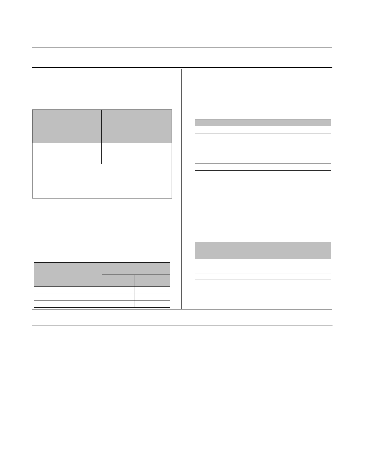
Specifications
656 Actuator
D100086X012
Maximum Recommended Casing Operating
Pressure
(1)
2.4 bar (35 psig)
(1a)
(2)(4)
,
Maximum
Diaphragm
Casing
Pressure
Bar (Psig)
Maximum Allowable Casing Pressure
Maximum
Actuator
Size
30 8.6 (125) 1.0 (15) 9.7 (140)
40 4.5 (65) 0.69 (10) 5.2 (75)
60 2.8 (40) 0.69 (10) 3.4 (50)
1a. Additional pressure may be added when the actuator is at full t ravel.If the
Maximum Excess DiaphragmPressure is exceeded,damage to the diaphragm or
diaphragm casing mightresult. Seethe Maximum Pressure Limitation section.
2a. Maximum diaphragmcasing pressuremust not beexceeded and must not
produce a force on the actuator stem greater than the maximumallowable actuator
output thrust or the maximumallowable stem load. See theMaximum Pressure
Limitation section.
3a. This maximumcasing pressure is not to be used fornormal operating pressure.Its
purpose is toallow for typical regulator supplysettings and/or relief valve tolerances.
Casing
Pressure for
Actuator
(2a)
Sizing
Bar (Psig)
,
Maximum
Excess
Diaphragm
Pressure
Bar (Psig)
Net Stem Force Output
See table 1
Springs Commonly Used with Rotary Valves
(2a,3a)
,
Operating Temperature Range
J -40 to 82C(-40to180F) with Nitrile Elastomer
J
-40 to 149C(-40to300F) with Silicone
Diaphragm
Construction Materials
Part Description Construction Material
Diaphragm Nitrile
Diaphragm plate and yoke Cast iron
Diaphragm casings, spring,
spring seats, travel stop, stem,
bearings, bearing seat, and
bearing race
Adjustment screw Brass
Casing Pressure Connection
1/4 NPT internal
Mounting and Stem Thread Information
Seefigure1
Actuator Weight
See table 2
Maximum Travel
Actuator Size
MAXIMUM RATED STEM
ACTUATOR SIZE
30 54 (2.125) Not available
40 89 (3.5) 76 (3)
60 105 (4.125) 97 (3.8125)
1. Control andstability may be impaired ifthis pressure isexceeded.
2. Exceeding thispressure can cause damage to the diaphragm, diaphragmcasing, or other parts.
3. For fluidand temperature capabilities of optionalmaterials, consultyour Emerson Process Management sales office
4. The pressure/temperaturelimits in this bulletinand any applicable standard or code limitation forvalve should not be exceeded
TRAVEL mm (INCHES)
Standard
Travel Stop
Optional
Travel Stop
Options
Top-mounted handwheel/adjustable travel stop
(4)
(3)
(standard)
Steel
Approximate
Shipping Weight,
kg (Pounds)
30 23 (50)
40 32 (70)
60 73 (160)
Ordering Information
When ordering, specify:
1. Actuator type and size
2. Spring range (see table 2)
3. Handwheel or optional travel stop
4. Loading pressure range and volume requirement
2
Page 3

656 Actuator
D100086X012
Product Bulletin
61.1:656
February 2013
Table 1. Stem Force Output and Other Actuator Data
(1)
Stem Fully
Retracted
NET STEMFORCE
Stem Fully Extended
(3)
Loading as Shown
ACTUATOR
SIZE
Maximum
Range
TYPICAL SPRINGS
Part Number Color Code
Metric Units
Bar --- --- Newtons Newtons Bar cm
30
40
60
0.17 to0.66
0.21 to0.86
0.29 to1.2
0.26 to1.3
0.27 to1.6
0.21 to1.8
0.21 to0.88
0.41 to1.9
0.30 to2.2
0.26 to0.90
0.24 to1.1
0.49 to1.9
0.48 to2.3
1F361627032
1K509827032
1N751527032
1F177027092
1F177127092
1F177227092
1L217427042
1L217327042
1N844027082
1K162727082
1N937327082
1K162827082
1P270227042
Aluminum and orange
Aluminum and dark green
Aluminum and red
Tan
Brown
Pink
White
Dark green
(5)
None
(5)
None
(5)
None
(5)
None
(5)
None
734
939
1321
1143
1232
939
1468
2802
2002
3541
3350
6503
6410
2322
1735
698
525
1699
1108
2424
1201
1632
5360
3336
3034
2224
US Units
Psig --- --- Pounds Pounds Psig SquareInches
2.5 to9.6
3.0 to12.5
30
4.3 to17.6
3.7 to18.4
3.9 to23.9
3.1 to26.1
3.1 to12.7
40
6.0 to27.4
4.3 to31.2
3.7 to13.1
60
3.5 to16.1
7.1 to27.0
6.9 to33.5
1. Others available;consult with your Emerson Process Management sales office for spring characteristics.
2. For maximum rated stemtravel with standard travel stop and zero handwheel limitation.
3. Stem forceequals initial spring compression withzero loading pressure.
4. Stem forceequals: (loading pressure X diaphragmarea with stemfully extended) minus force ofsprings at maximumcompression. Higherpressures canbeused,
but they must not exceed maximumallowable casing pressure or create stem force greater than safeload limit of any control device component.
5. Part numberstamped on spring.
1F361627032
1K509827032
1N751527032
1F177027092
1F177127092
1F177227092
1L217427042
1L217327042
1N844027082
1K162727082
1N937327082
1K162827082
1P270227042
Aluminum and orange
Aluminum and dark green
Aluminum and red
Tan
Brown
Pink
White
Dark green
(5)
None
(5)
None
(5)
None
(5)
None
(5)
None
165
211
297
257
277
211
330
630
450
796
753
1462
1441
522
390
157
118
382
249
545
270
367
1205
750
682
500
(2)
with Diaphragm
1.4
2.1
1.4
2.1
2.4
1.4
2.1
2.4
20 psig
30 psig
20 psig
30 psig
35 psig
20 psig
30 psig
35 psig
EFFECTIVE DIAPHRAGM AREA
(4)
,
Stem Fully
Retracted
Stem Fully
(3)
Extended
2
425 310
645 445
1387 1032
66 48
100 69
215 160
(4)
Table 2. Springs Commonly Used with Rotary Valves
INPUT SIGNAL
MAXIMUM RATED TRAVEL
SPRING PARTNUMBER
1. With standard travel stop and zero handwheel limitation.
2. For torqueoutputs using commonsprings, contactyour Emerson Process Management sales office.
WITH POSITIONER 1.4BAR(20PSIG) 2.4BAR(35PSIG)
WITHOUT POSITIONER 0.2to1.0BAR(3to15PSIG) 0.4to2.1BAR(6to30PSIG)
ACTUATOR SIZE 30 40 60 30 40 60
(1)
,mm(INCHES) 54 (2.125) 89 (3.5) 105 (4.125) 54(2.125) 89 (3.5) 105 (4.125)
(2)
1K509827032 1K217427042 1K162727082 1F177220792 1L217327042 1K162827082
3
Page 4

Product Bulletin
61.1:656
February 2013
Table 3. Dimensions
DIMENSION
ACTUATOR
SIZE
30 67 289 314 490 54 171 1/2-20 19 73 3/8-16 U NC
40 79 333 454 723 57 222 3/4-16 19 73 3/8-16 UNC
60 79 473 692 1014 64 222 3/4-16 32 99 1/2-13 UNC
30 2.62 11.38 12.38 19.32 2.12 6.75
30 3.12 13.12 17.88 28.38 2.25 8.75 0.75 2.88
40 3.12 18.62 27.25 39.94 2.50 8.75 1.25 3.88
A C
Without
Handwheel
E
With
Handwheel
H J
mm
Inches
S(Stem
Thread)
See above
X
Bolt Circle
Diameter
0.75 2.88
Figure 1. Dimensions (also see table 3)
J
1/4-18 NPT
656 Actuator
Y(4Holes)
D100086X012
Thread
See above
E
C
57
1
H
1U6162-C
A1506-1
Note:
1
Duplicated on opposite side: each hole 5/16-18 UNC-2B tapped 13 (0.50) deep.
S
A
(2.25)
X
Y
mm
(INCH)
Neither Emerson,Emerson Process Management, nor any of their affiliated entities assumes responsibility for the selection, use or maintenance
of any product. Responsibility for proper selection, use,and maintenance of anyproduct remains solely with thepurchaser and enduser.
Fisher is a markowned by one of the companiesin the Emerson ProcessManagement business unit of Emerson Electric Co. Emerson ProcessManagement,
Emerson, and the Emerson logo are trademar ks and service marks of Emerson Electric Co. All other marks are the property of their respective owners.
The contents of this publication are presented for informational purposes only, and while every effort has been made to ensure their accuracy, they arenot
to be construed as warranties or guarantees, express or implied, regarding the products or services described herein or their use orapplicability. All sales are
governed by our terms and conditions, which are available upon request. Wereserve the right to modify or improve the designs or specifications of such
products at any time without notice.
Emerson ProcessManagement
Marshalltown, Iowa 50158 USA
Sorocaba, 18087 Brazil
Chatham, Kent ME44QZ UK
Dubai, United Arab Emirates
Singapore 128461 Singapore
www.Fisher.com
E 1993, 2013 Fisher Controls InternationalLLC. All rights reserved.
4
 Loading...