


CF760AB00
Emerson CF760AB00, CF760AW00, CF760WW00, CF760BS00, CF760ORB00 Manual
...
WARNING: To avoid fire, shock, and serious personal injury, follow these instructions.
Safety Instructions
1. Read your owner’s manual carefully and keep it for future reference.
2. Before servicing or cleaning unit, switch power off at service panel and lock service panel
disconnecting means to prevent power from being switched on accidentally. When the service
disconnecting means cannot be locked, securely fasten a warning device, such as a tag, to the
service panel.
3. Be careful of the fan and blades when cleaning, painting, or working near the fan. Always turn off
the power to the ceiling fan before servicing.
4. Do not put anything into the fan blades while they are turning.
5. Do not operate reversing switch until fan blades have come to a complete stop.
Additional Safety Instructions for Installation
1. To avoid possible shock, be sure electricity is turned off at the fuse box before wiring, and do not
operate fan without blades.
2. The installation is to be in accordance with the National Electrical Code, ANSI/NFPA 70-1999 and
Local Codes. Use the National Electrical Code if Local Codes do not exist. The ceiling fan must be
grounded as a precaution against possible electrical shock. Electrical installation should be made
or approved by a licensed electrician.
3. The outlet box and joist must be securely mounted and capable of reliably supporting at least 50
pounds. Use only U.L. outlet boxes listed as “Acceptable for Fan Support”, and use the mounting
screws provided with the outlet box. Most outlet boxes commonly used for support of light fixtures are
not acceptable for fan support and may need to be replaced. Consult a qualified electrician if in doubt.
4. The downrod furnished with the fan provides the minimum recommended floor to fan blade
clearance for an 8 foot ceiling.
5. The fan must be mounted with the fan blades at least 7 feet from the floor to prevent accidental
contact with the fan blades.
6. Follow the recommended instructions for the proper method of wiring your ceiling fan. If you do not
know enough about electrical wiring, have your fan installed by a licensed electrician.
WARNING: To avoid fire, shock or injury, do not use an Emerson or any other brand of control not
specifically approved for this fan.
WARNING: This product is designed to use only those parts supplied with this product and/or any
accessories designated specifically for use with this product by Emerson Electric Co. Substitution of
parts or accessories not designated for use with this product by Emerson Electric Co. could result in
personal injury or property damage.
WARNING: To Reduce the risk of personal injury, do not bend the blade flange when installing the
blade flanges, balancing the blades or cleaning the fan. Do not insert foreign objects in between
rotating fan blades.
Part No. F40BP72870000 Form No. BP7287
READ AND SAVE THESE INSTRUCTIONS
60” DESIGNER
Net Weight: 30.0 Lbs.
Ceiling Fan
Owner's Manual
CF760AB00
CF760AW00
CF760WW00
CF760BS00
CF760ORB00
Model No.
CF760PW00
CF760WB00
WARNING
!
BP7287 60" DESIGNER FAN 3/10/05 10:42 AM Page 1

2
This Manual Is Designed to Make it as Easy as Possible for You to
Assemble, Install, Operate and Maintain Your Ceiling Fan
Tools Needed for Assembly
One Phillips head screwdriver
One stepladder
One 1/4” blade screwdriver
One wire stripper
Three wire connectors (supplied).
MATERIALS
Wiring outlet box and box connectors must
be of type required by the local code. The
minimum wire would be a 3-conductor (2wire with ground) of the following size:
Before assembly your ceiling fan, refer to
section on proper method of wiring your
fan (page 7). If you feel you do not have
enough wiring knowledge or experience,
have your fan installed by a licensed
electrician.
WARNING
!
Do not install or use fan if any part is
damaged or missing. Call Toll-Free:
1-800-654-3545
WARNING
!
This product is designed to use only
those parts supplied with this product
and/or any accessories designated
specifically for use with this product by
Emerson Electric Co. Substitution of
parts or accessories not designated for
use with this product by Emerson
Electric Co. could result in personal
injury or property damage.
WARNING
!
Installed W
ire Length Wire Size A.W.G.
Up to 50 ft. 14
50-100 ft. 12
Unpacking Instructions
For your convenience, check-off boxes are provided next to each step. As each
step is completed, place a check mark in the box. This will insure that all steps
have been completed and will be helpful in finding your place should you be
interrupted.
1. Check to see that you have received
the following parts:
NOTE: If you are uncertain of part
description, refer to exploded view
illustration.
a. Fan motor assembly
b. One switch housing assembly
c. Five fan blades
d. One ceiling cover
e. Five blade flanges
f. One hanger ball/downrod assembly
g. One hanger bracket
h. One coupling cover
i. One loose parts bag containing:
1. Sixteen 3/16-24 x 1/2”
slotted Phillips blade screws
2. Sixteen blade washers
3. Eleven 1/4-20 x 1/2” Phillips oval
head flange screws
4. One wood pendant
5. One coupling
6. Three wire connectors
7. Two threaded studs
8. Two knurled knobs
9. Two lockwashers
10. One clevis pin
11. One hairpin clip
BP7287 60" DESIGNER FAN 3/10/05 10:42 AM Page 2
LOOSE
PARTS
BAG
FAN MOTOR
ASSEMBLY
BLADE
FLANGES
CEILING
COVER
HANGER BALL/
DOWNROD
ASSEMBLY
HANGER
BRACKET
SWITCH CUP
ASSEMBLY
COUPLING
COVER
FAN
BLADES

3
It is critical that the clevis pin in the
motor coupling is properly installed and
the setscrews securely tightened. Failure
to verify that the pin and setscrews are
properly installed could result in the fan
falling.
WARNING
!
NOTE: Place the parts from the loose
parts bags in a small container to keep
them from being lost. If any parts are
missing, contact your local retailer or
catalog outlet for replacement before
proceeding.
2. Remove the fan assembly from the
protective plastic bag. Place the fan
assembly into the upper foam pad with
the bottom of the motor facing up.
The upper foam pad serves as a holder
for the fan during the first stages of
assembly.
How to Put Your Ceiling Fan Together
1. Remove the hanger ball by loosening
the setscrew in the hanger ball until the
ball falls freely down the downrod
(Figure 1). Remove the pin from the
downrod, then remove the hanger ball.
Retain the pin and hanger ball for
reinstallation in step 5.
2. Separate, untwist and unkink the three
80” motor leads. Route the motor lead
wires through the downrod. Remove
the upper setscrew from the motor
coupling. Align the clevis pin holes in
the downrod with the holes in the motor
coupling. Install the clevis pin and
secure with the hairpin clip (Figure 2).
The clevis pin must go through the
holes in the motor coupling and the
holes in the downrod. Be sure to push
the straight leg of the hairpin clip
through the hole near the end of the
clevis pin until the curved portion of the
hairpin clip snaps around the clevis pin.
The hairpin clip must be properly
installed to prevent the clevis pin from
working loose. Pull on the downrod to
make sure the clevis pin is properly
installed. Reinstall the upper setscrew
in the motor coupling. Check that the
lower setscrew is tightened securely
(Figure 2).
NOTE: The setscrews must be properly
installed as described above, or fan
wobble could result.
3. Make sure the grommet is properly
installed in the coupling cover, then
slide the coupling cover on the
downrod until it rests on the motor
housing. Place the ceiling cover over
the downrod. Be sure that the ceiling
cover and the coupling cover are both
oriented correctly (Figure 3).
Figure 1
Figure 2
Figure 3
BP7287 60" DESIGNER FAN 3/10/05 10:42 AM Page 3
HANGER
BALL
SETSCREW
DOWNROD
PIN
SETSCREW
CLEVIS
PIN
UPPER
SETSCREW
CEILING
COVER
MOTOR
COUPLING
CLEVIS
PIN
HAIRPIN
CLIP
MOTOR COUPLING
DOWNROD
CLEVIS PIN
HAIRPIN CLIP
SETSCREW
COUPLING
COVER
4
4. Reinstall the hanger ball (Figure 4) on
the downrod as follows. Route the
three 80” motor leads through the
hanger ball. Position the pin through
the two holes in the downrod and align
the hanger ball so the pin is captured in
the groove in the top of the hanger ball.
Pull the hanger ball up tight against the
pin and securely tighten the setscrew in
the hanger ball. Aloose setscrew could
create fan wobble.
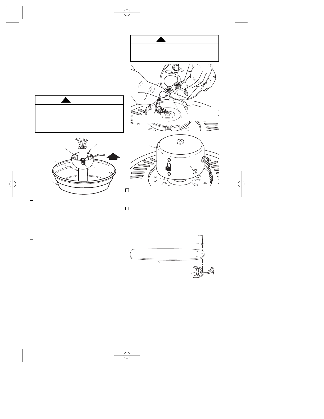
5.The fan comes with blue, black and
white leads that are 80” long. Before
installing fan, measure up
approximately 6 to 9-inches above top
of hanger ball/downrod assembly. Cut
off excess leads and strip back
insulation 1/2-inch from end of leads.
6. Engage the connector of the switch
housing assembly with the motor
connector (Figure 5). The two
connectors are keyed and color-coded
and must be mated correctly (color-tocolor) before they can be engaged.
Make sure the connector latch closes
properly.
7. Remove the three switch housing
mounting screws (Figure 5) from the
switch housing plate. Position the
switch housing assembly on the switch
housing plate and align the holes in the
switch housing assembly with the holes
in the plate. Secure the switch housing
assembly by installing the three screws
(Figure 6).
It is critical that the pin in the hanger ball
is properly installed and the setscrew
securely tightened. Failure to verify that
the pin and setscrew are properly
installed could result in the fan falling.
WARNING
!
To avoid possible fire or shock, do not
pinch wires between the switch cup
assembly and the switch cup plate.
WARNING
!
Figure 4
8. Turn fan assembly upside down in
preparation for mounting fan blade
assemblies.
9. Mount blade flanges to fan blades
using three 3/16-24 x 1/2” slotted
Phillips blade screws and three blade
washers (Figure 7).
NOTE: Take care not to scratch fan
housing when installing blades.
NOTE: Remove and discard the four
shipping spacers and screws from the
motor hub.
Figure 5
Figure 6
Figure 7
BP7287 60" DESIGNER FAN 3/10/05 10:42 AM Page 4
HANGER BALL
PIN
DOWNROD
CEILING
COVER
SETSCREW
SWITCH HOUSING
MOUNTING SCREW (3)
SWITCH
HOUSING
ASSEMBLY
3/16-24 x 1/2" SLOTTED
PHILLIPS BLADE SCREW (3)
BLADE WASHER (3)
FAN BLADE
BLADE FLANGE
SWITCH HOUSING
CONNECTOR
MOTOR CONNECTOR
MOUNTING
SCREWS (3)
 Loading...