


 1
1


 1
1 


 1
1
|
|
|
|
|
|
1 |
-1 |

YL
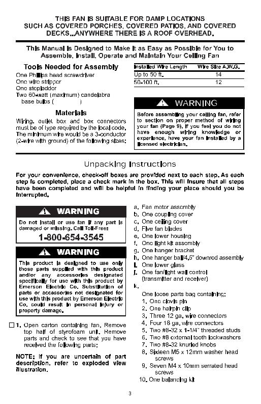
Supplied
Two 60-watt candelabra bulbs
l.

 k
k
l
Electrical Requirements |
Ceiling Fan Procedures |
IMPORTANT: Your ceiling fan will not function properly, and may be damaged, if used with any wall dimmer switch or control other than the Emerson Electric Fan/Light Wall Control supplied with the fan, or an optional Emerson Electric SR100 Remote Control.
Your new ceiling fan will require a grounded electrical supply line of 120 volts AC, 60 Hz, 15 amp circuit.
The outlet box must be securely anchored and capable of withstanding a load of at least 50 pounds.
!WARNING
To reduce the risk of fire, electric shock, or personal injury, mount fan to outlet box marked “Acceptable for Fan Support”, and use screws supplied with outlet box. Most outlet boxes commonly used for support of light fixtures are not acceptable for fan support and may need to be replaced. Consult a qualified electrician if in doubt.
If your fan is to replace an existing ceiling light fixture, turn electricity off at the main fuse or circuit breaker box at this time and remove the existing light fixture.
!WARNING
Turning off wall switch is not sufficient. To avoid possible electrical shock, be sure electricity is turned off at the main fuse or circuit breaker box before wiring. All wiring must be in accordance with National and Local codes and the ceiling fan must be properly grounded as a precaution against possible electrical shock.
General
Your Emerson ceiling fan comes supplied with a Fan/Light Wall Control which consists of a wall control (transmitter) and a remote control receiver mounted under the ceiling cover. This system allows you to regulate your ceiling fan speed and light intensity.
NOTE: An optional Emerson Electric SR100 Remote Control may also be used to control your ceiling fan.
How to Assemble Your Ceiling Fan
!WARNING
Turning off wall switch is not sufficient. To avoid possible electrical shock, be sure electricity is turned off at the main fuse or circuit breaker box before wiring. All wiring must be in accordance with National and Local codes and the ceiling fan must be properly grounded as a precaution against possible electrical shock.
IMPORTANT: Before assembling your ceiling fan, refer to sections “Setting Operating Frequency of Wall Control and Receiver” and “Installation of Wall Control”, Page 12. These sections instruct you how to: a) Set the operating frequency of the fan/light wall control and the remote control receiver; and b) Install the fan/light wall control in the wall box. You will then be ready to proceed with the assembly and installation of your ceiling fan, as follows:
5


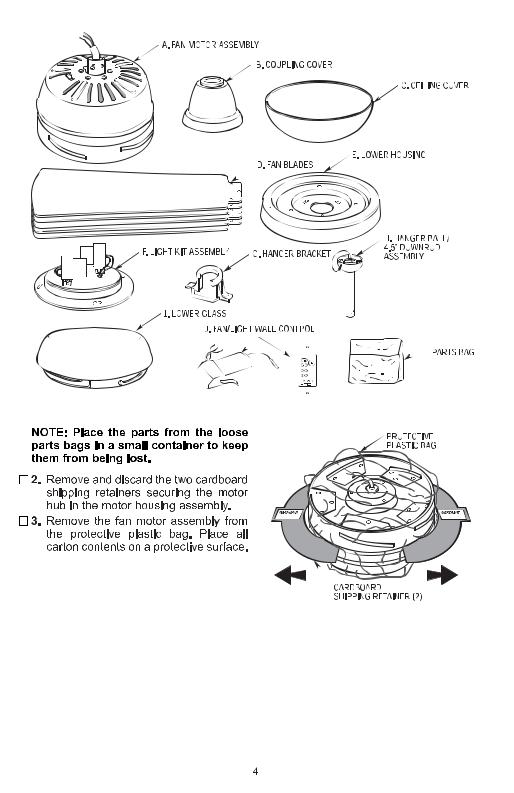
 1. Remove the hanger ball by loosening the setscrew in the hanger ball until the ball falls freely down the downrod (Figure 1). Remove the clevis pin from the downrod, then remove the hanger ball. Retain the pin and hanger ball for reinstallation in step 5.
PIN
HANGER
BALL
DOWNROD
SETSCREW
SETSCREWSETSCREW(2)
CLEVIS PIN
Figure 2
DOWNROD |
HAIRPINPIN CLIP |
CLIP |
MOTOR
COUPLING
MOTOR
COUPLING
Figure 1

 2. Loosen setscrew in motor coupling if necessary. Separate, untwist and unkink the three 80” motor leads. Route the motor lead wires through the downrod. Align the clevis pin holes in the downrod with the holes in the motor coupling. Install the clevis pin and secure with the hairpin clip (Figure 2). The clevis pin must go through the holes in the motor coupling and the holes in the downrod. Be sure to push the straight leg of the hairpin clip through the hole near the end of the clevis pin until the curved portion of the hairpin clip snaps around the clevis pin. The hairpin clip must be properly installed to prevent the clevis pin from working loose. Pull on the downrod to make sure the clevis pin is properly installed.

 3. While pulling up on the downrod, securely tighten the two setscrews in the motor coupling (Figure 3).
NOTE: The setscrews must be properly installed as described above, or fan wobble could result.

 4. Make sure the grommet is properly installed in the coupling cover then slide the coupler cover on the downrod until it rests on the motor housing. Place the ceiling cover over the downrod. Be sure both the ceiling cover and the coupler cover are oriented correctly (Figure 3).
CEILING
CANOPY
!WARNING
It is critical that the clevis pin in the motor coupling is properly installed and the setscrew securely tightened. Failure to verify that the pin and setscrew are properly installed (as shown in Figure 2) could result in the fan falling.
HAIRPIN |
COUPLER |
CLIP |
COVER |
MOTOR |
CLEVIS PIN |
COUPLING |
|
|
SETSCREW (2) |
Figure 3
6
 Loading...