


4430BFFR_FTN _A LK4430BFFR_FTN_A
Owners Manual
Models 4430BF1UFR*, 4430BF1LFR* and 4430BF1MFR* Tri-Level Tubular Bottle Filler Fountain and
Sanitary Freeze Resistant Triple Valve Control Assembly
4430B
MODEL (LK)4430BF1UFR
INSTALLER
4430BFFR Fountains are among the easiest to install Fountains on the market today. To assure you install these models easily and correctly, PLEASE READ THESE SIMPLE INSTRUCTIONS
BEFORE STARTING THE INSTALLATION. CHECK YOUR INSTALLATION FOR COMPLIANCE
WITH PLUMBING, ELECTRICAL,AND OTHERAPPLICABLE CODES.After installation, save these instructions for future reference.
PAGE 1 |
1000004247 (Rev. C - 03/20) |

4430BFFR_FTN _A LK4430BFFR_FTN_A
INSTALLATION INSTRUCTIONS
IMPORTANT
ALL SERVICE TO BE PERFORMED BY AN AUTHORIZED SERVICE PERSON
IMPORTANT! INSTALLER PLEASE NOTE.
THE GROUNDING OF ELECTRICAL EQUIPMENT SUCH AS TELEPHONE, COMPUTERS, ETC. TO WATER LINES IS A COMMON PROCEDURE. THIS GROUNDING MAY BE IN THE BUILDING OR MAY OCCUR AWAY FROM THE BUILDING. THIS GROUNDING CAN CAUSE ELECTRICAL FEEDBACK INTO A FOUNTAIN, CREATING AN ELECTROLYSIS WHICH CAUSES A METALLIC TASTE OR AN INCREASE IN THE METAL CONTENT OF THE WATER. THIS CONDITION IS AVOIDABLE BY USING THE PROPER MATERIALS AS INDICATED. ANY DRAIN FITTINGS PROVIDED BY THE INSTALLER SHOULD BE MADE OF PLASTIC TO ELECTRICALLY ISOLATE THE FOUNTAIN FROM THE BUILDING PLUMBING SYSTEM.
IMPORTANT! INSTALLER PLEASE NOTE
*For freeze resistant valve to function properly, the valve must be installed in a non-freezing area or below frost line.
*Tubing must be cut to right length. Do not coil any excess tubing or it will cause the valve to malfunction.
*Do not pull up on lines coming out of the PVC column. This raises the water valve above the frost line. Use the nylon strap (ref. Item 10) to lift the unit to prevent damage to the valve.
General Installation Tips
1.Be sure to flush water supply line before you connect it to the inlet fitting on Freeze Resistant Valve System.
2.There is one combined drain line required for this unit that is for the drinking fountain basin and/or bottle filler drains and the valve/water supply line system. The bowl drain is the 1-1/2" PVC fitting at the bottom of the 8" PVC tube and the valve drains back up to the bowl drain through the air gap assembly (provided). Provide ample drainage. It's always better to have too much than not enough.
3.The column (8" PVC tube) must remain vertical. Be sure it remains vertical when backfilling the excavating trench.
4.When the concrete pad, for mounting the fountain is poured, be sure to allow adequate space around the top of the column for servicing the valve.
5.We recommend that the top of the column be flush or slightly above the top height of the concrete pad.
6.You should test the unit before you backfill. Simply blow on the clear, small diameter tubing. A steady stream should flow from the braided tubing line. When air pressure is removed from the clear tubing the water stream should stop.
7.Once you have tested the valve, backfilled the hole and poured the concrete mounting pad you are ready to set the fountain. After bolting the fountain in place connect the air control valve tubing, supply water tubing and drain lines. The water supply line must have a straight run from the basin bubbler down to the control valve. If a straight run is not maintained water will become trapped and freeze leaving the unit inoperable. Test the fountain again. If it fails to work, the air control line may be kinked or connected improperly. Be sure to keep water out of the air control line.
8.These products are designed to operate on 20 PSI to 105 PSI supply line pressure. If inlet pressure above 105 PSI, a pressure regulator must be installed in the supply line. Any damage caused by reason of connecting this product to supply line pressure lower than 20 PSI or higher than 105 PSI is not covered by warranty.
INSTALLATION INSTRUCTIONS FOR INSTALLING SANITARY FREEZE
TRIPLE VALVE CONTROL ASSY.
1.Prepare trench for water supply and waste drain lines (if required by local codes). The hole should be deep enough to accommodate the PVC column and 5 cubic feet of porous fill (large broken rock). Additional porous fill may be required due to local ground conditions. (See Site Preparation Detail below).
2.Lay drain lines and water supply lines. Provide service shut off valve for maintenance. Flush the water supply line before attaching to the shut off valve.
3.Set PVC column in excavating pit. Connect the water supply line to the inlet on the PVC column. Remove valve assembly from the PVC column by carefully pulling up on the nylon strap. Pressure test the valve assembly for leaks. Check operation of the water valve by blowing on the small clear diameter tubing.
A steady stream of water should flow from the braided tubing. After releasing air pressure from the small clear tubing the water stream should stop.
4.Replace the water valve into the PVC column. Make sure the supply hose coils into the bottom of the PVC column without any kinks. Cap the PVC column, protect the ends of the connecting tubes and backfill the trench. Keep the PVC column vertical at all times.
5.Form the concrete mounting pad and locate the fountain 3/8" minimum fasteners (not included) in the proper position. (Refer to Rough-in for correct location of fasteners.) (Fasteners not included). Pour concrete and finish. Be sure to keep concrete away from the top of the PVC column to allow removal of PVC cap to allow for future service. Let concrete set 4 hours minimum before mounting fountain.
6.Double check that the water valve is positioned fully at the bottom of the PVC column. Install insulation into the PVC column and push down onto the top of the water valve.
7.Mount the fountain onto the 3/8" minimum fasteners. (Fasteners not included). Level and shim fountain as required.
8.Connect the drain line, water line and air control lines. Excess lengths should be trimmed from the tubing. The water supply line must be positioned for positive drain back out of the fountain and down through the water valve. Any water allowed to be trapped above the frost line will freeze leaving the unit inoperable.
Do not pull up on the connection lines as this could raise the valve above the frost line.
9.Check for proper operation by using fountain push buttons. If the valve does not work properly check for leaks or kinks in the air control line.
10.After insuring proper operation reassemble fountain. Installation of your fountain is now complete.
1000004247 (Rev. C - 03/20) |
PAGE 2 |

4430BFFR_FTN _A LK4430BFFR_FTN_A
SUGGESTED SITE PREPARATION DETAIL FOR THE SANITARYFR3 VALVE
36" MIN. (914mm) |
60"MAX. (1524mm) FROST LINE
4" PVC 1/4 BEND
1-1/2" DRAIN TUBE (SUPPLIED BY INSTALLER)
(SUPPLIED BY INSTALLER)
4" PVC PIPE
(SUPPLIED BY INSTALLER)
CONCRETE SLAB
4" |
CLEANOUT PLUG FOR ACCESS |
(SUPPLIED BY INSTALLER) |
|
102mm |
|
MIN. 8 INCH INSIDE DIA. PVC PIPE, TRIM TO DESIRED LENGTH (SUPPLIED BY INSTALLER)
PVC 8" x 8" x 4" COMBINATION "Y" & 1/8 BEND REDUCING ASSY. (SUPPLIED BY INSTALLER)
MIN. 8 INCH INSIDE DIA. PVC PIPE, TRIM TO DESIRED LENGTH (SUPPLIED BY INSTALLER)
WATER INLET LINE ( BY INSTALLER )
DRAIN LINE BY INSTALLER
( AS REQUIRED BY LOCAL CODES )
FIG. 1
PAGE 3 |
1000004247 (Rev. C - 03/20) |
4430BFFR_FTN _A LK4430BFFR_FTN_A
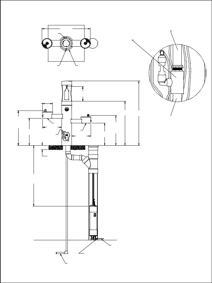
SUGGESTED SITE PREPARATION DETAIL FOR THE 4430BF1UFR FTN. WHEN USING THE SANITARYFR3 VALVE
|
|
|
48" |
|
|
|
1-1/2 DRAIN TUBE |
|
|
|
1219mm |
|
|
|
SUPPLIED WITH FTN. |
|
|
|
A |
|
|
|
AIR GAP ASSY. |
|
|
|
|
|
|
|
|
|
|
|
|
|
|
|
SUPPLIED WITH VALVE |
1/2" ( 13mm ) DIA. HOLES (6 PL) |
O 14" |
|
|
|
|||
SPACED AS SHOWN ON A |
356mm |
|
|
|
|||
12" ( 305mm ) BOLT CENTER |
|
|
|
|
|||
|
|
|
|
14 9/16" |
|
|
|
|
|
|
|
371mm |
|
|
|
|
O 254mm10" |
|
|
|
|
|
|
|
|
|
|
|
|
44 1/16" |
64 1/16" |
|
|
|
|
|
|
1119mm |
1627mm |
34 11/16" |
|
|
|
|
|
|
1-1/2 DRAIN TUBE |
881mm |
|
|
B |
|
|
29 13/16" |
SUPPLIED BY INSTALLER |
ORIFICE |
|
|
|
|
|||
HEIGHT |
27 1/8" |
|
19" |
B |
|
757mm |
Detail A |
|
|
483mm |
|
ORIFICE |
|||
|
|
|
|
|
HEIGHT |
|
|
|
689mm |
SEE DETAIL A |
19" |
22 1/4" |
|
||
|
|
565mm |
|
||||
|
|
(ON PAGE 4) |
483mm |
|
|
|
|
|
|
|
4" |
|
|
|
|
|
|
|
102mm |
|
|
|
|
36" MIN. 914mm |
|
|
|
|
|
||
60" MAX. 1524mm |
|
|
|
|
|
||
|
FROST LINE |
|
|
|
|
|
|
|
|
|
|
|
|
FIG. 2 |
|
|
|
|
|
|
|
WATER INLET LINE |
|
|
|
|
|
|
|
( BY INSTALLER ) |
|
|
|
|
|
VALVE WATER LINE SUPPLIED |
|
||
|
|
|
|
WITH A 1/4 x 1/2 NPT CONNECTOR |
|
||
DRAIN LINE BY INSTALLER
LEGEND ( AS REQUIRED BY LOCAL CODES )
A = ACCESS PANEL ( 8" X 10" )
B = REMOVABLE BOTTOM COVER
1000004247 (Rev. C - 03/20) |
PAGE 4 |
 Loading...