

Page 1

Doc. N. 595R36300 Edition 1.0.6 – 02/2020
SERVICE MANUAL
BLAST CHILLER FREEZER RANGE 30 50 70 2020
Page 2

SERVICE MANUAL Blast Chiller Freezer SKCH 30 50 70
Document made by Product Care – Technical Training & Service – Vallenoncello PN/Italy
All the images and information of this document are property of ©Electrolux Professional Spa. This document and
all of its contents cannot be copied or used, in part or entirely without the written authorization of Electrolux Professional Spa.
©Electrolux Professional Spa.
DOC NUMBER 595R36300 2
Page 3

SERVICE MANUAL Blast Chiller Freezer SKCH 30 50 70
EDITION
DESCRIPTION
DATE
1.0.0
First publication
FEBRUARY. 2019
1.0.1
Modification pag 3.12.13.14
JUNE 2019
1.0.2
Modification pag 12.26.35.40.63.65.71.101.121
JULY 2019
1.0.3
Modification pag 17.38.63.109.110.111.132.133.134
JULY 2019
1.0.4
Modification pag 4.19.22.23.68.81
SEPTEMBER 2019
1.0.5
Modification pag 1.54
OCTOBER 2019
1.0.6
Modification pag 1.67 to 74.160
FEBBRARY 2020
REVISIONS UPDATE:
Foreward
The service manual (here in after Manual) provides the engineer with information necessary for correct and
safe use of the machine (or “appliance“).
The following must not be considered a long and exacting list of warnings, but rather a set of instructions suitable for improving machine performance in every respect and, above all, preventing injury to persons and animals and damage to property due to improper operating procedures.
All persons involved in machine transport, installation, commissioning, use and maintenance, repair and disassembly must consult and carefully read this manual before carrying out the various operations, in order to
avoid wrong and improper actions that could compromise the machine's integrity or endanger people.
If, after reading this manual, there are still doubts regarding machine use, do not hesitate to contact the Manufacturer or the Customer Care to receive prompt and precise assistance for better operation and maximum
efficiency of the machine. During all stages of machine assessment, always respect the current regulations on
safety, work hygiene and environmental protection. It is the user's responsibility to make sure the machine is
started and operated only in optimum conditions of safety for people, animals and property.
IMPORTANT
• The manufacturer declines any liability for operations carried out on the appliance without respecting
the instructions given in this manual.
• The manufacturer reserves the right to modify the appliances presented in this publication without no-
tice.
• No part of this manual may be reproduced without the consent of the manufacturer.
• This manual is available in digital format by:
o contacting the dealer or reference customer care;
o downloading the latest and up to date manual/technical bulletin(s) on the web site;:
trolux.com/professional.
The manual must always be part of the documentation available when servicing the machine.
www.elec-
DOC NUMBER 595R36300 3
Page 4

SERVICE MANUAL Blast Chiller Freezer SKCH 30 50 70
6 GN 1/1
10 GN 1/1
10 GN 2/1
6 GN 1/1
10 GN 1/1
10 GN 2/1
Change
Change
6 GN 1/1
10 GN 1/1
10 GN 2/1
6 GN 1/1
10 GN 1/1
10 GN 2/1
208V 3~
208V 3~
208V 3~
208V 3~
208V 3~
MODELS COVERED BY THE SERVICE MANUAL
This manual is relative to the following list of appliances.
MODEL TYPE
30 KG
BUILT IN
50 KG
BUILT IN
70 KG
BUILT IN
30 KG
REMOTE
50 KG
REMOTE
70 KG
REMOTE
DESCRIPTION
VOLTAGE
GAS REF.
CLIMATC
CLASS
AMPERE
REFR.
QUANTITY g.
IP
PROTECTION
PASTRY
60X40
380/415V
3~ 50HZ
R452
R404a
PASTRY
60X40
380/415V
3~ 50HZ
R452
R404a
PASTRY
60X40
380/415V
3~ 50HZ
R452
R404a
PASTRY
60X40
380/415V
3~ 50HZ
Change
term.valve
PASTRY
60X40
380/415V
3~ 50HZ
term.valve
5 5 5 5 5 5
6.3 8.4 11.5 4.4 8.6 8.6
1150 2000 3000 / / /
X4 X4 X4 X4 X4 X4
PASTRY
60X40
380/415V
3~ 50HZ
term.valve
MODEL TYPE
USA
30 KG
BUILT IN
50 KG
BUILT IN
70 KG
BUILT IN
30 KG
REMOTE
50 KG
REMOTE
70 KG
REMOTE
DESCRIPTION
PASTRY
60X40
VOLTAGE
GAS REF.
CLIMATC
CLASS
AMPERE
KW
REFR.
QUANTITY g.
IP
PROTECTION
208V 3~
60HZ
R448A R448A R448A R448A R448A R448A
MCA 15
MOP 35
2.7 4.5 5.5
1150 2000 3000 / / /
X4 X4 X4 X4 X4 X4
PASTRY
60X40
60HZ
PASTRY
60X40
60HZ
PASTRY
60X40
60HZ
PASTRY
60X40
60HZ
PASTRY
60X40
60HZ
5 5 5 5 5 5
MCA 24
MOP 60
MCA 31
MOP 80
/ / /
DOC NUMBER 595R36300 4
Page 5

SERVICE MANUAL Blast Chiller Freezer SKCH 30 50 70
INDEX
1. GENERAL INFORMATION ...........................................................................................10
1.1 GENERAL INFORMATION .................................................................................................................... 10
1.2 SAFETY INFORMATION/PRECAUTIONS ............................................................................................ 11
1.3 PERSONAL PROTECTION EQUIPMENT ............................................................................................ 12
1.4 GENERAL SAFETY INFORMATION ..................................................................................................... 13
1.4.1 Residual Risks ................................................................................................................................. 13
1.5 SAFETY SIGNS TO BE PLACED NEAR THE M ACHINE AREA ........................................................ 15
1.6 DATA PLATE (IDENTIFICATION STICKER) / QR-Code sticker ........................................................... 16
1.6.1 Serial Number (Production Date) .................................................................................................... 17
1.7 TECHNICAL DATA AND DRAWINGS WITH MEASUREMENTS ......................................................... 18
1.8 GENERAL REFERENCE TO APPLICABLE PRODUCT CERTIFICATIONS ....................................... 19
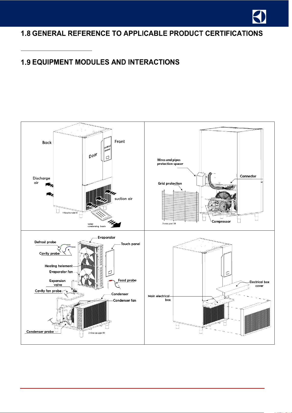
1.9 EQUIPMENT MODULES AND INTERACTIONS .................................................................................. 19
1.9.1 Blast chiller /freezer 50 kg 10 gn 1/1 and 70 kg 10 gn 2/1 ............................................................. 19
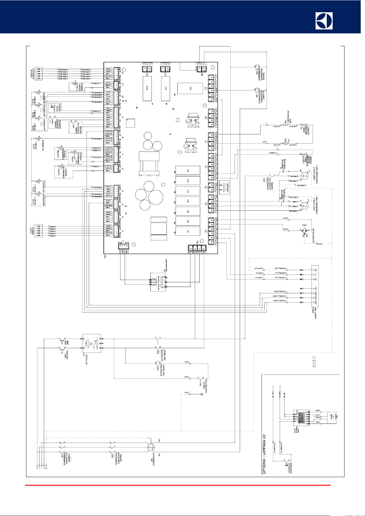
1.9.2 Electrical schema interactions 50_70 kg Europa ........................................................................... 20
1.9.3 Electrical schema interactions 50_70 kg USA ................................................................................. 21
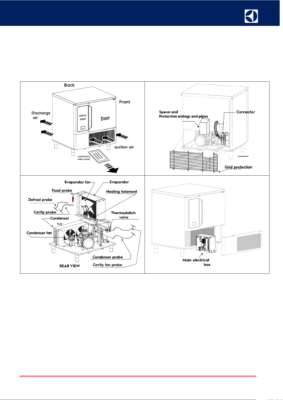
1.9.4 Blast chiller /freezer 30kg 6 gn 1/1 .................................................................................................. 22
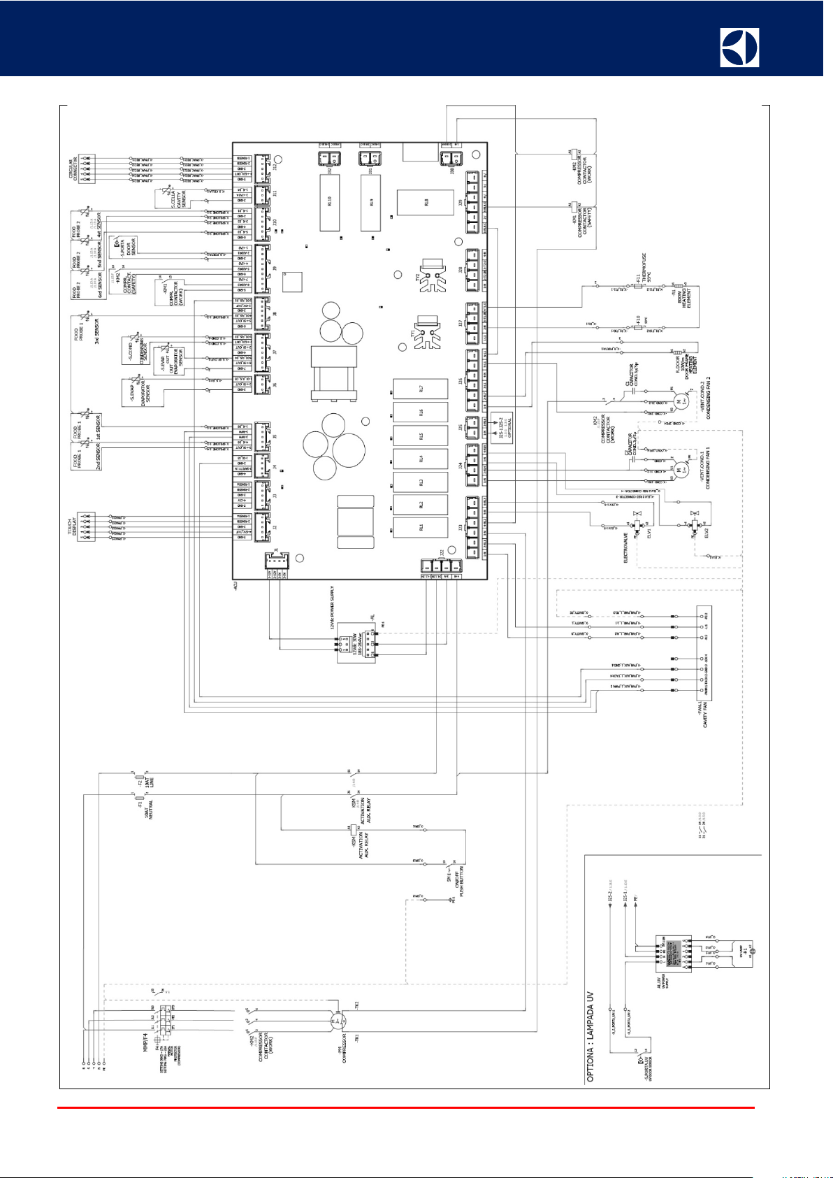
1.9.5 Electrical schema interactions 30 kg Europa .................................................................................. 23
1.9.6 Electrical schema interactions 30 kg USA ....................................................................................... 24
1.10 DEFINITIONS/GLOSSARY.................................................................................................................. 25
2. INSTALLATION AND COMMISSIONING .....................................................................26
2.1 INSTALLATION ...................................................................................................................................... 26
2.2 PRE-CONNECTION PREPARATIONS ................................................................................................. 26
2.3 LIST OF POSSIBLE INSTALLATION SOLUTIONS .............................................................................. 27
2.4 ROOM REQUIREMENTS ...................................................................................................................... 27
2.5 REFRIGERATION POWER OF REMOTE UNIT ................................................................................... 27
2.5.1 Refrigeration power table ................................................................................................................ 27
2.6 CONNECTION REMOTE UNIT ............................................................................................................. 28
2.6.1 Technical Instructions / Installation Precautions ............................................................................. 28
2.6.2 General Information ......................................................................................................................... 28
2.6.3 Basic Installation – Overview ........................................................................................................... 28
2.6.4 Installation Steps ............................................................................................................................. 29
2.6.5 System Evacuation .......................................................................................................................... 30
2.6.6 Procedures for Refrigerant Charge ................................................................................................. 30
2.6.7 Piping ............................................................................................................................................... 31
2.6.8 Basic Accessories of a Cooling System .......................................................................................... 32
DOC NUMBER 595R36300 5
Page 6

SERVICE MANUAL Blast Chiller Freezer SKCH 30 50 70
2.6.9 Expansion Valve .............................................................................................................................. 34
2.6.10 Setting the Expansion valve .......................................................................................................... 34
2.6.11 Correct position of the thermostatic sensor ................................................................................... 34
2.6.12 Identification of the thermostatic valve .......................................................................................... 35
2.6.13 Charge MOP .................................................................................................................................. 36
2.6.14 Quantity of refrigerant to charge .................................................................................................... 36
2.6.15 Electrical connection ...................................................................................................................... 37
2.6.15.1 Electrical box drawing on remote unit ................................................................................ 37
2.6.15.2 Electrical box in the BCF: IE. Of clamp connections ...................................................... 38
2.7 UNPACKING AND POSITIONING THE EQUIPMENT .......................................................................... 39
2.8 COMMISSIONING ................................................................................................................................. 40
2.8.1 Power connection on bcf 380/400V ................................................................................................. 40
2.8.2 Power connection on bcf 208V (USA) ............................................................................................. 40
2.8.3 Description Main Display ................................................................................................................. 41
2.8.3.1 Icon description, Message of Dialogues .............................................................................. 42
2.8.4 Softwar update ................................................................................................................................ 44
2.8.5 Programming file ............................................................................................................................. 45
2.8.5.1 How to update: ..................................................................................................................... 45
2.8.6 Programming parameters ................................................................................................................ 46
2.8.6.1 How to update: ..................................................................................................................... 46
2.8.7 Pnc & ser upload (pncserial.json) .................................................................................................... 47
2.8.7.1 How to update pnc & ser (pncserial.json): ........................................................................... 47
2.8.7.2 How to install update pnc & ser (pncserial.json): ................................................................. 50
2.8.8 Usb data transfer ............................................................................................................................. 52
2.8.8.1 Users management lite ........................................................................................................ 52
2.8.8.2 What follows is a diagram to show menu navigation ........................................................... 52
2.8.8.3 Select types .......................................................................................................................... 53
2.8.8.4 Select type ............................................................................................................................ 53
2.8.8.5 Select file .............................................................................................................................. 54
2.8.8.6 Select file or add new file ..................................................................................................... 54
2.8.8.7 Enter file name ..................................................................................................................... 55
2.8.8.8 Select Items .......................................................................................................................... 55
2.8.8.9 Confirm ................................................................................................................................. 56
2.8.8.10 Replace or add items ......................................................................................................... 56
2.8.8.11 Skip, Duplicate, Add ........................................................................................................... 57
2.8.8.12 Enter item name ................................................................................................................. 57
2.8.8.13 Types list for service:.......................................................................................................... 58
2.8.8.14 File names .......................................................................................................................... 58
2.8.8.15 Item names ......................................................................................................................... 58
2.8.8.16 Errors and Warnings: ......................................................................................................... 58
2.8.9 How to acess to service area .......................................................................................................... 60
2.8.9.1 How to show the “data monitor” ........................................................................................... 61
2.8.9.2 How to exit from “data monitor” and “bypass” ..................................................................... 61
2.8.9.3 How to enter in “bypass” ...................................................................................................... 61
2.8.9.4 How to upload the pnc and serial number............................................................................ 61
2.8.9.5 How to upload the parameter and interogation .................................................................... 61
DOC NUMBER 595R36300 6
Page 7

SERVICE MANUAL Blast Chiller Freezer SKCH 30 50 70
2.8.9.6 Service ambiente explanation .............................................................................................. 62
2.9 WIZARD ................................................................................................................................................. 69
2.9.1 Installation wizard check .................................................................................................................. 69
2.9.2 Manual Test Wizard ......................................................................................................................... 77
2.9.2.1 Start manual wizard .............................................................................................................. 77
3. USE OF APPLIANCE ....................................................................................................80
3.1 OPERATING INSTRUCTIONS .............................................................................................................. 80
3.2 PREVENTIVE MAINTENANCE PLAN (FOR SERVICE): OPERATION FREQUENCY ....................... 80
4. DETAILED APPLIANCE AND COMPONENTS DESCRIPTION/FUNCTIONING ......81
4.1 MAIN BOARD “PETRA” ......................................................................................................................... 81
4.1.1 Functionality..................................................................................................................................... 81
4.2 USER INTERFACE “TOUCH”................................................................................................................ 82
4.2.1 Functionality touch panel ............................................................................................................. 82
4.2.2 PMH power supply 100-240 Vac to 12V dc ..................................................................................... 83
4.3 SEMI-ERMETIC COMPRESSOR .......................................................................................................... 84
4.3.1 Over view ......................................................................................................................................... 84
4.3.2 Expected use of the unit .................................................................................................................. 84
4.3.3 What follows is forbidden: ................................................................................................................ 84
4.3.4 Compressor identification ................................................................................................................ 84
4.3.5 Airing of the installation room .......................................................................................................... 84
4.3.6 Pipes Connections ........................................................................................................................... 85
4.3.7 Table of pipe connection of Dorin compressor ................................................................................ 86
4.3.8 Electrical connections ...................................................................................................................... 86
4.3.9 Protection System ........................................................................................................................... 87
4.3.10 Commissioning: Preliminary Works ............................................................................................... 87
4.3.11 Compressors Replacement ........................................................................................................... 88
4.3.12 Compressor Disassembly .............................................................................................................. 88
4.3.13 Number of starts ............................................................................................................................ 88
4.3.14 Rotalock Valves ............................................................................................................................. 89
4.3.15 Crankcase heater installations ...................................................................................................... 90
4.3.16 Electrical Connection Of The Compressor On The Unit ............................................................... 91
4.3.17 Evaporator Fan .............................................................................................................................. 92
4.3.17.1 Functionality fan ................................................................................................................. 92
4.3.17.2 Electrical Connections Fan ................................................................................................ 93
4.3.18 Probe’s ........................................................................................................................................... 94
4.3.18.1 Probe’s feature ................................................................................................................... 94
4.3.18.2 Electrical Connections Probes ........................................................................................... 94
4.3.18.3 Probe functions .................................................................................................................. 95
4.3.19 Food Probe .................................................................................................................................... 95
4.3.19.1 Functionality ....................................................................................................................... 95
DOC NUMBER 595R36300 7
Page 8

SERVICE MANUAL Blast Chiller Freezer SKCH 30 50 70
4.3.19.2 Electrical Connections Food Probes .................................................................................. 98
4.3.20 Heater Evaporator ......................................................................................................................... 99
4.3.20.1 Functionality ....................................................................................................................... 99
4.3.20.2 Electrical Connections Evaporator Heater ......................................................................... 99
4.3.21 Test Digital I/O: Step By Step Digital Operable Components Testing ........................................ 100
4.3.22 Identify rapid“test cycles and components” ................................................................................. 100
5. TROUBLESHOOTING .................................................................................................102
5.1 TECHNICIAN TROUBLESHOOTING .................................................................................................. 102
6. SERVICING THE APPLIANCE ...................................................................................108
6.1 LIST OF NEEDED TOOLS .................................................................................................................. 108
6.1.1 Ordinary Tools ............................................................................................................................... 108
6.1.2 Special Tools: List, Description And Spare Part Code Per Each Special Tool ............................. 108
6.2 IMPORTANT PROCEDURES FOR INSTALLATION .......................................................................... 109
6.2.1 Storage of components ................................................................................................................. 109
6.2.2 Cleaning the pipes ......................................................................................................................... 109
6.2.3 Installation of refrigeration system components ............................................................................ 109
6.3 REPLACING EQUIPMENT COMPONENTS ....................................................................................... 110
6.3.1 Disassembly/Reassemble Of Components Range 50_70 Kg ....................................................... 110
6.3.1.1 Accessing the components on the back side of the appliance .......................................... 110
6.3.1.2 Rack supports .................................................................................................................... 110
6.3.1.3 Cell probe (blue) ................................................................................................................. 111
6.3.1.4 Evaporator probe (grey) ..................................................................................................... 112
6.3.1.5 Food probe ......................................................................................................................... 114
6.3.1.6 Condenser probe (black) .................................................................................................... 115
6.3.1.7 Outevaporator probe (green) ............................................................................................. 115
6.3.1.8 Thermostat ......................................................................................................................... 116
6.3.1.9 Evaporator fan .................................................................................................................... 116
6.3.1.10 Heating element ............................................................................................................... 118
6.3.1.11 Comand Panel .................................................................................................................. 118
6.3.1.12 Control Panel .................................................................................................................... 119
6.3.1.13 Frame heating element cable ........................................................................................... 119
6.3.1.14 Evaporator ........................................................................................................................ 120
6.3.1.15 Electrical box .................................................................................................................... 122
6.3.1.16 Compressor ...................................................................................................................... 123
6.3.1.17 Solenoid valve .................................................................................................................. 124
6.3.1.18 Finned Coil Condenser .................................................................................................... 125
6.3.1.19 Condenser fan .................................................................................................................. 127
6.3.1.20 Tanic receiver ................................................................................................................... 127
6.3.1.21 Dehidrator Filter ................................................................................................................ 127
6.3.1.22 Door .................................................................................................................................. 128
6.3.1.23 Door gasket ...................................................................................................................... 128
6.3.1.24 Door switch ....................................................................................................................... 128
6.3.1.25 Thermostatich valve ......................................................................................................... 129
Access display and replacement of mambrane sticker .................................................... 130
6.3.2 Disassembly/Reassemble Of Components Range 30 Kg ............................................................. 133
6.3.2.1 Accessing the components on the back side of the appliance .......................................... 133
DOC NUMBER 595R36300 8
Page 9

SERVICE MANUAL Blast Chiller Freezer SKCH 30 50 70
6.3.2.2 Rack supports .................................................................................................................... 134
6.3.2.3 Cell probe (blue) ................................................................................................................. 135
6.3.2.4 Evaporator probe (grey) ..................................................................................................... 136
6.3.2.5 Food probe ......................................................................................................................... 137
6.3.2.6 Condenser probe (black) .................................................................................................... 138
6.3.2.7 Out evaporator probe (green) ............................................................................................ 138
6.3.2.8 Thermostat ......................................................................................................................... 139
6.3.2.9 Evaporator fan .................................................................................................................... 139
6.3.2.10 Heating element ............................................................................................................... 141
6.3.2.11 Command Panel ............................................................................................................... 141
6.3.2.12 Control Panel .................................................................................................................... 142
6.3.2.13 Frame heating element cable ........................................................................................... 142
6.3.2.14 Evaporator ........................................................................................................................ 143
6.3.2.15 Electrical box .................................................................................................................... 145
6.3.2.16 Compressor ...................................................................................................................... 146
6.3.2.17 Solenoid valve .................................................................................................................. 147
6.3.2.18 Finned Coil Condenser .................................................................................................... 148
6.3.2.19 Condenser fan .................................................................................................................. 150
6.3.2.20 Tanic receiver ................................................................................................................... 150
6.3.2.21 Dehydrator Filter ............................................................................................................... 150
6.3.2.22 Door .................................................................................................................................. 151
6.3.2.23 Door gasket ...................................................................................................................... 151
6.3.2.24 Door switch ....................................................................................................................... 151
6.3.2.25 Thermostatich valve ......................................................................................................... 152
Access display and replacement of mambrane sticker .................................................... 153
6.3.3 Preventive Maintenance Plan ........................................................................................................ 156
6.3.3.1 Refert to document “Check list preventive maintenance ................................................... 156
7. RELATED DOCUMENTS ............................................................................................156
7.1 EXPLODED VIEW ............................................................................................................................... 156
7.1.1 List Of The Vital and Wear&Tear Parts ......................................................................................... 156
7.1.2 List Of Available Accessories ........................................................................................................ 156
7.1.3 List Of Consumables ..................................................................................................................... 156
7.1.4 List Of Spares Wear And Tear ...................................................................................................... 156
7.2 ELECTRICAL WIRING DIAGRAM ....................................................................................................... 156
7.3 PARAMETERS LIST: ........................................................................................................................... 157
DOC NUMBER 595R36300 9
Page 10

SERVICE MANUAL Blast Chiller Freezer SKCH 30 50 70
1. GENERAL INFORMATION
To ensure safe use of the machine and a proper understanding of the manual it is necessary to be familiar
with the terms and typographical conventions used in the documentation. The following symbols are used in
the manual to indicate and identify the various types of hazards:
WARNING
Danger for the health and safety of operators.
WARNING
Danger of electrocution - dangerous voltage.
CAUTION
Risk of damage to the machine or the product.
WARNING
Danger of magnetic fields.
IMPORTANT
Important instructions or information on the product
Read the instructions before using the appliance
Clarifications and explanations
• Only specialised personnel are authorised to operate on the machine.
• This appliance must not be used by minors and adults with limited physical, sensory or mental
abilities or without adequate experience and knowledge regarding its use.
– Do not let children play with the
– Keep all packaging and detergents away from children.
– Cleaning and user maintenance shall not be made by children without supervision.
• Do not store explosive substances, such as pressurized containers with flammable propellant, in
this appliance or close to the appliance
• Do not remove, tamper with or make the machine “CE“ marking illegible.
• Refer to the data given on the machine’s data plate “CE“ marking for relations with the Manufacturer
(e.g. when ordering spare parts, etc.).
• When scrapping the machine, the “CE“ marking must be destroyed.
appliance.
DOC NUMBER 595R36300 10
Page 11

SERVICE MANUAL Blast Chiller Freezer SKCH 30 50 70
• Risks mainly of a mechanical, thermal and electrical nature exist in the machine. Where possible the risks
have been neutralised:
– directly, by means of adequate design solutions.
– indirectly by using guards, protection and safety devices.
• During maintenance several risks remain, as these could not be eliminated, and must be
neutralised by adopting specific measures and precautions.
• Do not carry out any checking, cleaning, repair or maintenance operations on moving
parts. Workers must be informed of this prohibition by means of clearly visible signs.
• To guarantee machine efficiency and correct operation, periodical maintenance must be carried out
according to the instructions given in this manual.
• Make sure to periodically check correct operation of all the safety devices and the insulation of
electrical cables, which must be replaced if damaged.
• Extraordinary machine maintenance operations must only be carried out by specialized Technicians
provided with all the appropriate personal protection equipment (safety shoes, gloves, glasses, overalls, etc.), tools, utensils and ancillary means.
• Never operate the machine, removing, modifying or tampering with the guards, protection or safety devices.
• Before carrying out any operation on the machine, always consult the manual which gives the correct
procedures and contains important information on safety.
DOC NUMBER 595R36300 11
Page 12

SERVICE MANUAL Blast Chiller Freezer SKCH 30 50 70
—
●
○
—
○
—
●
○
— —
—
●
●
— —
Installation
●
●2
●
Normal use
●
●
●
1
○
—
—
○ ●
●
1 or 2
○
—
cleaning
○ ●
●
○
—
Maintenance
○ ●
○ ○
—
○ ●
○ ○
—
● ● ●
—
●
PPE REQUIRED
○
PPE AVAILABLE OR TO BE USED IF NECESSARY
—
PPE NOT REQUIRED
Summary table of the Personal Protection Equipment (PPE) to be used during the various stages of the machine's service life.X
Stage
Transport
Handling
Unpacking
Adjustments
Routine cleaning
Extraordinary
Dismantling
Scrapping
Protective
garments
—
○
●
Safety
footwear
●
Gloves Glasses
○
○
1 or 2
Safety
helmet
—
Key:
1.
2.
During these operations, the worn gloves must be heatproof to protect hands from contact with hot
food or hot parts of the appliance and/or when removing hot items from
protection equipment by operators, specialized personnel or users can involve exposure to chemical
risk and possible damage
During these operations, the worn gloves must be cut-resistant.
tion equipment by operators, specialized personnel or users can involve exposure to damage
health (depending on the
to
health (depending on the
model).
model).
Failure to use the personal
it.
Failure to use the personal protec-
to
DOC NUMBER 595R36300 12
Page 13

SERVICE MANUAL Blast Chiller Freezer SKCH 30 50 70
Contact with live parts during maintenance operations carried out with
the electrical panel powered
The machines are provided with electric and/or mechanical safety devices for protecting workers and the machine
itself. Therefore, the user must not remove or tamper with such devices. The Manufacturer declines any liability
for damage due to tampering or their non-use.
Never operate the machine, removing, modifying or tampering with the guards, protection or safety devices.
Do not make any modifications to the parts supplied with the appliance.
Several illustrations in the manual show the machine, or parts of it, without guards or with guards removed. This
is purely for explanatory purposes.
Do not use the machine without the guards or with the protection devices deactivated.
Do not remove, tamper with or make illegible the safety, danger and instruction signs and labels on the machine.
Air recirculation must take into account the air necessary for combustion, 2 m³/h/kW of gas power, and also the
"well-being" of persons working in the kitchen.
Inadequate ventilation causes asphyxia.
Do not obstruct the ventilation system in the place where this appliance is installed.
Do not obstruct the vents or ducts of this or other appliances.
Place emergency telephone numbers in a visible position.
The measured sound level emitted “A“ does not exceed 70 dB (“A“).
Turn the appliance off in case of fault or poor operation.
Do not use products (even if diluted) containing chlorine (sodium hypochlorite, hydrochloric or muriatic acid, etc.)
to clean the appliance or the floor under it.
Do not use metal tools to clean steel parts (wire brushes or Scotch Brite type scouring pads).
Do not allow oil or grease to come into contact with plastic parts.
Do not allow dirt, fat, food or other residuals to form deposits on the appliance.
Do not spray water or use steam to clean the equipment.
Do not store or use gasoline or other flammable vapours, liquids or items near this or any other appliance.
Do not spray aerosols near this appliance while it is in operation.
Never check for leaks with an open flame.
1.4.1 Residual Risks
The machine has several risks that were not completely eliminated from a design standpoint or with the installation of adequate protection devices. Nevertheless, through this manual the Manufacturer has taken steps to
inform operators of such risks, carefully indicating the personal protection equipment to be used by them. Sufficient spaces are provided for during the machine installation stages in order to limit these risks.
To preserve these conditions, the areas around the machine must always be:
Kept free of obstacles (e.g. ladders, tools, containers, boxes, etc.);
Clean and dry;
Well lit.
For the Customer's complete information, the residual risks remaining on the machine are indicated below: such
actions are deemed improper and therefore strictly forbidden.
Residual risk Descripti on of hazardous situa tion
Slipping or falling The operator can slip due to water or dirt on the floor
Burns/abrasions (e.g. heating elements)
Electrocution
Tipping of loads
Mechanical safety characteristics, hazards
DOC NUMBER 595R36300 13
The operator deliberately or unintentionally touches some components
inside the machine without using protective gloves
When handling the machine or the packing containing it, using unsuitable lifting systems or accessories or with the unbalanced load
Page 14

SERVICE MANUAL Blast Chiller Freezer SKCH 30 50 70
Mechanical safety characteristics, hazards
The appliance does not have sharp edges or protruding parts. The guards for the moving and live parts are fixed
to the cabinet with screws, to prevent accidental access.
Protection devices installed on the machine
The guards on the machine are:
(e.
fixed guards
release connectors that can only be removed or opened with tools.
g. casings, covers, side panels, etc.), fixed to the machine and/or frame with screws or quick-
DOC NUMBER 595R36300 14
Page 15

SERVICE MANUAL Blast Chiller Freezer SKCH 30 50 70
Prohibition Meaning
Do not remove the safety devices
Do not use water to extinguish fires (placed on electrical parts)
Danger Meaning
Danger of burns
Keep the area around the appliance clear and free from combustible materials. Do not keep flammable materials in the vicinity of
the appliance
Install the appliance in a well-ventilated place to avoid the creation
of dangerous mixtures of unburnt gases in the same room
Danger of electrocution (shown on electrical parts with indication of
voltage)
Risk of electromagnetic fields
Access forbidden to wearers of electrical stimulator (pacemakers)
End of use: When the appliance is no longer to be used, make it unusable by removing the mains power
supply wiring.
DOC NUMBER 595R36300 15
Page 16

SERVICE MANUAL Blast Chiller Freezer SKCH 30 50 70
F.Mod.
Factory model description
Comm.Model
Commercial description
Type Ref.
Refer to model of family (used on spc)
PNC
Production number code
Ser.No
Serial number
V
Power supply voltage / phase
Hz
Power supply frequency
kW
Max. Power input
A
Current absorption
Cyclopentane
Expanding gas used in insulation
IP
Dust and water protection rating
CE
CE marking
L
Logo IMQ/GS
Refrigerant Type
Gas type used
Climatic class
Refer to climatic test
Defrost power
KW
GWP
Global Warning Potential
CO2 eq
Quantity of greenhouse gases
CAP.
Nominal capacity
Electrolux Professional
The main identification sticker is located bottom left side and under condenser panel. QR-Code sticker on control
panel upper side (visible when opening the door) The meaning of the various information is listed below:
The meaning of the various information is listed below.
Legend of data plate
SPAViale Treviso, 15
33170Pordenone (Italy)
DOC NUMBER 595R36300 16
Manufacturer:
Page 17

SERVICE MANUAL Blast Chiller Freezer SKCH 30 50 70
18 YEAR
1.6.1 Serial Number (Production Date)
The serial is necessary to find the correct spare part or to ask tech. support.
EXAMPLE: Serial Number
8 01 1 0001
01 WEEK
0001 APPLIANCE
MANUFACTURED
DOC NUMBER 595R36300 17
Page 18

SERVICE MANUAL Blast Chiller Freezer SKCH 30 50 70
Max High
30KG 6GN
50KG 10GN
70KG 10GN
Models
X Y Z
30KG 6GN
50KG 10GN
70KG 10GN
Please, for technical data and overall drawings refer to Installation Manual available on website www.electro-
lux.com/professional.
Table reference of dimensional units
Models
1/1
1/1
2/1
The minumum entrance dimension, if you dismantle the door,condenser panel,hinge,door microswicth support
top (if necessary) refer to letter Z:
Width
mm
897 937 1130 1050 1484 169_(rem.155)
895 939 1800 1720 1482 240_(rem.220)
1250 1092 1800 1720 1873.3 320_(rem.290)
Deep
mm
1/1
1/1
2/1
(adj.level)
mm
726 551 862
726 551 864
1051 662 1017
Min High
(adj.level)mm
Whit door open Weight KG
DOC NUMBER 595R36300 18
Page 19
SERVICE MANUAL Blast Chiller Freezer SKCH 30 50 70
Please, for overall certifications refer to Conformity Certificate and Conformity Declaration available on website
www.electrolux.com/professional
.
1.9.1 Blast chiller /freezer 50 kg 10 gn 1/1 and 70 kg 10 gn 2/1
DOC NUMBER 595R36300 19
Page 20

SERVICE MANUAL Blast Chiller Freezer SKCH 30 50 70
1.9.2 Electrical schema interactions 50_70 kg Europa
DOC NUMBER 595R36300 20
Page 21

SERVICE MANUAL Blast Chiller Freezer SKCH 30 50 70
1.9.3 Electrical schema interactions 50_70 kg USA
DOC NUMBER 595R36300 21
Page 22
SERVICE MANUAL Blast Chiller Freezer SKCH 30 50 70
1.9.4 Blast chiller /freezer 30kg 6 gn 1/1
DOC NUMBER 595R36300 22
Page 23
SERVICE MANUAL Blast Chiller Freezer SKCH 30 50 70
1.9.5 Electrical schema interactions 30 kg Europa
DOC NUMBER 595R36300 23
Page 24
SERVICE MANUAL Blast Chiller Freezer SKCH 30 50 70
1.9.6 Electrical schema interactions 30 kg USA
DOC NUMBER 595R36300 24
Page 25
SERVICE MANUAL Blast Chiller Freezer SKCH 30 50 70
COMPONENTS
DEFINITION
EXPLANATION
Cavity fan probe
Probe
Set the On Off cavity Fans
Cavity probe
Probe
Set the temperature of cavity
Compressor
Pump
Suction and discharge the refrigerant gas
Condenser
Heat exchanger
Reduce the temperature. of refrigerant from high to low)
Condenser fan
Fans
Fan taking the hot temperature off
Condenser probe
Probe
Temperature sensor of the condenser
Connect. term. board
Plate connections
Main SS plate where is connected all device present on cavity
Electrical box
Main electronic com.
Box with all electronic components (boards fuse, etc.)
Evaporator
Heat exchanger
Remove the hot air in the cavity
Evaporator fan
Fans
Fan to uniformity the cavity temperature.
Evaporator probe
Probe
Temperature sensor of the evaporator
Food probe
Probe (multi sensor)
Temperature sensor of food product
HP
Pressure
HP= High pressure side discharge compressor
LP
Pressure
Lp=Lower pressure side suction compressor
Thermostatic valve
Expansion valve
Increase or degrees the injection of refrigerant on evaporator
DOC NUMBER 595R36300 25
Page 26

SERVICE MANUAL Blast Chiller Freezer SKCH 30 50 70
2. INSTALLATION AND COMMISSIONING
Refer to IN (Installation manual) code 595R361””
Refer to the installation drawing for information about supply power connection and general clearances of the
unit sides from walls and ceiling.
IMPORTANT: servicing the unit requires access to the rear side; it is therefore needed to either provide
enough space to move the unit from its working position or installing the unit with space enough all around it.
IMPORTANT for remote connections piping configuration:
servicing the unit requires access to the rear side; it is therefore needed to either provide enough space to
move the unit from its working position or installing the unit with space enough all around it.
Furthermore, it is highly recommended connecting the unit by using hoses in at least three turns, like shown in
the picture below, to allow acceptable movement of the unit without causing damages or fractures (picture reports the scheme of 30kg model).
DOC NUMBER 595R36300 26
Page 27

SERVICE MANUAL Blast Chiller Freezer SKCH 30 50 70
RELATIV HUMID-
CONDENSATION
MASS OF STEAM
3
25°C
60%
16,7°C
12,0 g/kg
4
30°C
55%
20,0°C
14,8 g/kg
5
40°C
40%
23,9°C
18,8 g/kg
7
35°C
75%
30,0°C
27,3 g/kg
-10 -20 -36 -40
881156 H290CS R404A 6570 4520 2050 1590 A IR 40°C 30 meters
881157 H390CS R404A \ 5870 3430 \ AIR 40°C 30 meters
881158 H505CS R404A 11740 8130 3690 2850 A IR 40°C 30 meters
881159 H751CS R404A 15990 11110 6010 \ A IR 40°C 30 meters
881160 H1001CS R404A 22190 14490 7190 5570 A IR 40°C 30 meters
881168 H290CS R404A 6570 4520 2050 1590 WA TER 10° to 30° 30 meters
881170 H390CS R404A \ 5870 3430 \ W A TER 10° to 30° 30 meters
881171 H505CS R404A 11740 8130 3690 2850 WA TER 10° to 30° 30 meters
881172 H751CS R404A 15990 11110 6010 \ WA TER 10° to 30° 30 meters
881173 H505CS R404A 11740 8130 3690 2850 A IR and WATER 40°C 30 meters
881221 H290CS R452A 6310 4350 2030 1590 A IR 40°C 30 meters
881222 H390CS R452A \ 5770 3380 \ A IR 40°C 30 meters
881223 H505CS R452A 11650 8040 3600 2770 A IR 40°C 30 meters
881224 H751CS R452A 15620 10870 5910 \ A IR 40°C 30 meters
881225 H1001CS R452A 21760 15140 7100 5560 A IR 40°C 30 meters
881226 H290CS R452A 6310 4350 2030 1590 WA TER 10° to 30° 30 meters
881227 H390CS R452A \ 5770 3380 \ W A TER 10° to 30° 30 meters
881228 H505CS R452A 11650 8040 3600 2770 WA TER 10° to 30° 30 meters
881229 H751CS R452A 15620 10870 5910 \ WA TER 10° to 30° 30 meters
881230 H505CS R452A 11650 8040 3600 2770 A IR and WATER 40°C 30 meters
EVAP TEM in WATT
PNC REM OT E UNI T
COM PRESSOR
AM B.
TEMP./
Wate r
tem p.
MAX pipe s USED
Type Gas
CONDENSA T IO N
1. Casters: models with built-in cooling unit (no remote configuration).
2. Plinth: guarantee free access to the unit rear side.
3. Marine feet: guarantee free access to the unit rear side.
4. Remote configuration: see IMPORTANT note at 2.7.1.
5. Stack with oven: 30kg model (see the information below).
INFORMATION:
with the stacking kit, optional accessory of the 30kg 6gn1/1BCF (595R441--).
BCF 30kg model can be stacked under Oven. Reference installation instructions available
According to IEC/EN 60335-2-89 and IEC/EN ISO 23953, room requirements depend on the unit climatic class:
see the table below.
For the specific unit climatic class refer to the installation manual and to the unit data plate.
CLIMATIC CLASS
TEMPERATURE
ITY
POINT
PRESENT IN THE AIR
2.5.1 Refrigeration power table
DOC NUMBER 595R36300 27
Page 28

SERVICE MANUAL Blast Chiller Freezer SKCH 30 50 70
2.6.1 Technical Instructions / Installation Precautions
The instructions below are general guidelines, but they do contain the major points that shall be taken into account for proper and safe product installation for assuring best performances and preventing warranty voidance.
Caution: Refrigeration systems are pressurized circuits! It is therefore of the utmost importance that
the condensing units are removed and / or installed only by technically qualified personnel, with
knowledge of the equipment and of the processes to be adopted.
2.6.2 General Information
Inspect the unit for detecting possible damages occurred during the transport: report to the carrier immediately if any damage.
The warranty does not cover damage due to storage, transport or installation of the condensing unit
carried out in the wrong position.
Warning: Make sure you have read and understand all procedures and caution messages before
you execute any maintenance or installation tasks! It is imperative – for your own safety - that the testing
devices used are functioning well and properly sized.
2.6.3 Basic Installation – Overview
The installation site shall be well ventilated, ensuring that there will be sufficient air flow behind the condenser
(refer to Figure 1)
Figure 1 – Natural airflow through the roof
If the flow of air to the condenser is limited (or even partially blocked), system performance and reliability can be
drastically reduced. Condensing units are designed to operate at ambient temperatures up to 43°C (110°F).
Therefore, make sure that the temperature at the installation site does not exceed the recommended limit.
Warning: it is necessary to periodically clean the condenser, so that no particles damage or block
the air circulation.
Warning: pay the utmost attention when working with flammable refrigerants.
DOC NUMBER 595R36300 28
Page 29

SERVICE MANUAL Blast Chiller Freezer SKCH 30 50 70
2.6.4 Installation Steps
INFORMATION:
Select and size the equipment needed to assemble the refrigeration system according to the project specifications
(pipes, valves, accessories, condensing unit). Carefully observe the scope for each model.
IMPORTANT: Size pipe/hose based on the condensing unit dimensions (do not size based on the evapo-
rator).
Phases
1. Weld the pipes to the condensing unit and evaporator connections. Check the seal (leak test) in
all soldered or threaded connections.
2. Obtain the vacuum in the circuit (check with the pressure gauge if the vacuum is stable).
3. Fill the required refrigerant mass (kg): the gas should preferably be charged in the liquid phase.
4. To ascertain the correct behavior of the system, switch ON and monitor:
a. Low/high pressures
b. Liquid/gas lines suction temperatures
5. If detecting low performance or excessive pressures, fine tune the set up by either filling more
refrigerant or discharging it until reaching the correct pressures/temperatures (see below additional general notes for more details).
Refrigerant mass set up:
• Taking into account both the temperature set on the BCF chamber and the temperature where the remote
condenser is installed, when the liquid/gas lines suction temperature gets closer to the design values, proceed
with the final adjustments (phase 5 mentioned above).
• The superheating at the evaporator (given by the difference between temperatures at the piping surface at
the point where the expansion valve's sensor is fixed, and the evaporation temperature
5°C and 10°C (9°F and 18°F). Superheating at the compressor’s inlet must be between 10°C and 15°C
(18°F and 27°F), where in such case it is the difference between the temperature at the surface of the return
pipe, at a distance 150 mm (6") from the compressor, and the evaporation temperature. The sub-cooling in
the condenser shall be between 3°C and 10°C (5°F and 18°F), i.e., the condensing temperature less than
the temperature at the pipe's surface at the condenser's outlet.
(*) Evaporation temperature obtained by converting the suction pressure into temperature.
Cleaning the System (in case condensing unit replacement):
• Cleaning the system before installing a new condensing unit is mandatory to completely remove residues and
other contaminants.
• The manufacturer recommends the installation of a filter-dryer at the suction line during the cleaning operation
to retain and filter any undesired particles
• It is recommended to make the joints by braze-welding
Welding operations:
• While welding keep nitrogen (N2) circulating into the pipes with a pressure between 1 and 2 psig (equivalent
to 1.08 - 1.15 bar): this will prevent oxidations and scale forming, hence ensuring that the piping is free from
any contaminants (oil, grease, oxides).
• Use a damp cloth when welding valves or fittings or pipes to prevent the components overheatingbecause of
the heat propagation.
• The compressor and the filter- dryer are extremely susceptible to humidity. As such, they shall only be opened
during installation or replacement phases. In case of opening, do not leave them exposed to air for more than
10 min.
Leakage test
• During the system leakage tests, never pressurize the pipes using air, oxygen or acetylene. There is a poten-
tial risk of fire and/or explosion.
(*)) shall be between
DOC NUMBER 595R36300 29
Page 30

SERVICE MANUAL Blast Chiller Freezer SKCH 30 50 70
• After the installation is finished, pressurize the system using nitrogen and/or a small refrigerant charge up to
100 psig (equivalent to 7,8 bar); never use pressures higher than 150 psig (equivalent to 11.35 bar) for preventing the low-pressure switch damage.
.
(Figure 2) Leakage tests with soapy water bubbles
• Check for leaks using an electronic detector or a halide detector (torch). An alternative method is to check
leakage with soapy water bubbles (see Figure 2). When all fittings are properly checked, depressurize the
system and go to the next step.
2.6.5 System Evacuation
Warning: Never use the compressor itself to evacuate the system, nor energize the system when it
is under vacuum, as it may cause the compressor be damaged because of short-circuit caused by overload.
To evacuate the system, use a high vacuum pump and a vacuum gage. The system shall be evacuated up to
0,5mmHg (equivalent to 0,0066bar) or less. In any case, at least 20 minutes of vacuum must be applied (see
Figure 3)
Figure 3 – Vaccum operation scheme
Warning: Never use anti-freeze elements (methyl alcohol and derivates), as they cause irreversible
damages to the cooling system.
2.6.6 Procedures for Refrigerant Charge
The refrigerant shall only be charged after the proper vacuum has been achieved. Please check on the compressor or condensing unit tag what is the type of refrigerant that should be used to charge the system. Break the
vacuum only when the compressor is switched off.
It is recommended that the refrigerant charge be provided in the liquid state (with the compressor switched off),
through the high side (tank liquid valve) and by the refrigerant mass measurement (kg), according to the system
specification.
DOC NUMBER 595R36300 30
Page 31

SERVICE MANUAL Blast Chiller Freezer SKCH 30 50 70
Wait for 15 minutes before switching on the system again, to allow the gas to be evenly distributed and balance
the pressure levels.
The fine-tuning of the refrigerant charge must be done while the system is running (compressor switched on), by
observing the sight glass. The charge will be complete when there are no more bubbles forming.
When performing a condensing unit replacement always check the specified refrigerant charge.
2.6.7 Piping
Piping shall be sized so that:
It is flexible, to avoid rupture due to expansion and due to the transmission of vibration usually caused by compressors.
Ensure that the refrigerant is well distributed through the evaporator(s), and prevent the liquid from flowing back
to the compressor. To do that, use an expansion valve with proper dimensions, and an inverted siphon at the
outlet of each evaporator.
Figure 4 – Evaporator under the condensing unit
Prevent the liquid from flowing back to the compressor when the system stops and the evaporator(s) is/are located
above the Condensing Unit, using an inverted siphon and suction accumulator (see Figure 4).
Aid the return of lubricating oil coming from the evaporator(s) to the system where the Condensing Unit is located
over 3000 mm above the evaporator(s), using an inverted siphon every 3000 mm in the piping.
Allow secondary operations, such as attaching measurement instruments, isolating stretches for maintenance
purposes and pump down.
Warning: The diameter of the fittings for the condensing units and evaporators shall not be used as
a parameter to select the diameters of the other system components.
Warning: After replacement the condensing unit and its accessories must be handled and recycled
according to the material group (ferrous, non-ferrous, polymers, oils,) directives. These recommendations are intended to minimize the adverse impacts on the environment.
DOC NUMBER 595R36300 31
Page 32

SERVICE MANUAL Blast Chiller Freezer SKCH 30 50 70
Suction Accumulator
2.6.8 Basic Accessories of a Cooling System
Filter-Dryer
Installed at the liquid line, its function is to retain particles and mainly remove
residual humidity from the system.
Sight Glass
It is installed at the liquid line, just after the filter -dryer and used to monitor
the system refrigerant charge. Some models also allow humidity detection.
Pressure Control
Some Condensing Units are fitted with High / Low Pressure Switches. Their
function is to prevent the compressor from operating under pressure levels
that are outside of their application range.
Solenoid Valve
It is installed at the liquid line, prior to the expansion valve and used for the
pump down procedure.
Oil Separator
It is installed at the discharge line, when the evaporator is below the compressor's height (long distances)
It is installed at the suction line, just before the compressor. It prevents liquid
refrigerant from flowing back towards the compressor.
Conditions that favor the flow-back of liquid to the compressor and where the
use of a suction accumulator is recommended:
• Systems with more than one evaporator
• High refrigerant charges
• Operations with defrosting by hot gas
• Where the distance from the compressor to the evaporator is over 15 me-
ters (50 feet)
• Evaporator(s) above the condensing unit
Fan Speed Control
DOC NUMBER 595R36300 32
The Fan Speed Control controls the head pressure in air-cooled condensers
by reducing the fan speed to maintain head pressure as the outside temperatures/condenser pressure drops. As the motor speed drops under lower ambient/load condition fan noise is also reduced.
Page 33

SERVICE MANUAL Blast Chiller Freezer SKCH 30 50 70
Fuse plug
to let pressure escape. In case of release the melt part replace with new one
Schrader Valve
Used for service operation (Refrigerant Charge).
Suction Filter
It is recommended to clean the systems if the compressor has burned out. Installed at the suction line, its main task is to retain the contaminants (result of
the burning of the compressor), and to retain system particles.
A/C systems can include a pressure release valve that is usually mounted at
the compressor or fuse plug mounted on the receiver dryer.The relief valve can
open at a preset pressure and then reclose.The center of the fuse plug melts
same capacity.
DOC NUMBER 595R36300 33
Page 34

SERVICE MANUAL Blast Chiller Freezer SKCH 30 50 70
2.6.9 Expansion Valve
It is installed at the liquid line, before the evaporator.
Its function is to keep the pressure different between the condenser and the evaporator; it also adjusts the refrigerant flow within the evaporator. For systems operating under low evaporating temperatures (lower than -17.7°C
(0°F), it is recommended using an expansion valve fit with MOP (Maximum Operation Pressure), to protect the
compressor against high pressures during the suction phase at the start of the procedure.
2.6.10 Setting the Expansion valve
The valve is already set from factory in the standard condition and it is suitable for most installations.
If adjustment is needed, it is possible proceeding by means of the expansion valve rod adjustment.
By rotating the rod clockwise, the expansion valve overheat increases, while turning the rod counterclockwise
then it will decrea the overheating
IMPORTANT: Turn the rod maximum 45° each time; wider rotations will provoke flash-gas!
To eliminate evaporator swing, increase overheating by turning the rod clockwise until it stops.
Rotate the rod anticlockwise step by step until the swing will reappear.
From this position, turn the rod 45° clockwise.
When the calibration is done (swing approximately at the average), the refrigerator will no longer swing and the
evaporator can be considered as working at full capacity (see Figure 5).
If overheating in the evaporator is too high, this may be either due to an insufficient refrigerant fluid mass or to a
insufficiend dimension of the thermostatic valve (thermostatic valve not sized correctly).
Note: Variations of the overheating of ± 0.5 ° C are not considered swing.
Figure 5
2.6.11 Correct position of the thermostatic sensor
It is recommended to mount the sensor on a horizontal section of the suction line as close to the evaporator as
possible and in a position corresponding to the watch hands between 1 and 4.
Figure 6
DOC NUMBER 595R36300 34
Page 35

SERVICE MANUAL Blast Chiller Freezer SKCH 30 50 70
The position depends on the external diameter of the tube.
When the suction pipe has an outside diameter of 16 mm or less, it can be secured both in the positions (see
Figure7):
a. above the suction line
b. by the side of its own path, in horizontal position
Figure 7
When the tube has a diameter greater than 16 mm, the sensor must be secured beneath the horizontal axis of
the tubing itself to form a 45 ° angle with the same horizontal axis (see Figure 8)
Figure 8
Warning
The sensor must never be mounted at the bottom of the suction line, as it will
:
receive false control pulses due to the oil present at the bottom of the tube itself.
2.6.12 Identification of the thermostatic valve
The thermostatic element is equipped with a laser engraving on the top of the membrane (see Figure 9).
This engraving indicates the type of valve (with the numerical code), the field of evaporation temperature, MOP
point, the refrigerant and the maximum operating pressure and the type of nozzle installed
Figure 9
DOC NUMBER 595R36300 35
Page 36

SERVICE MANUAL Blast Chiller Freezer SKCH 30 50 70
2.6.13 Charge MOP
All MOP valves have a very small charge in the sensor.
This means that the valve or the element should be placed in the hottest position of the sensor otherwise a charge
migration may occur from the sensor to the element and the expansion valve will stop working.
The MOP charge has a limited charge in the sensor.
MOP means Maximum Operating Pressure (sometimes called “Motor Overload Protection”) and is the maximum
suction / evaporation pressure allowed in the suction / evaporation line.
The refrigerant liquid will evaporate when the temperature reaches the MOP point. As the suction pressure increases, the expansion valve starts reducing the pressure to 0.3 / 0.4 bar, below the MOP point, until fully closing
when the suction pressure will be equal to the MOP point.
2.6.14 Quantity of refrigerant to charge
The exact quantity of refrigerant to charge (see Figure 10) in the system depends on:
Figure 10
Data plate identification (in case of remote unit the reference are points 2 and 3)
Liquid container receiver (max quantity in kg of refrigerant)
Liquid spy (see Figure 11) on the system.(where present)
Figure 11
COMPLETE OPERATIONS IN SUMMARY - After correct cleaning and vacuum of the system:
a) Start to charge the refrigerant on suction/service pipe on the compressor.
b) Keep the appliance door opened
c) Switched ON the appliance
d) Charge a small amount of refrigerant step by step without freezing the pipe until air bubbles show on liquid spy.
e) Close the door and verify the evaporation pressure.
f) Check the overheating on external pipe of evaporator following the evaporation pressure/temperature
g) Check for presence of swing of pressure due to thermostatic valve (refer to chapter 2.5.10)
h) In case of swings, set the valve or add refrigerant.
Warnings: Do not provoke flash gas!!!!! The pipe must be slightly cooled not frozen!!
DOC NUMBER 595R36300 36
Page 37

SERVICE MANUAL Blast Chiller Freezer SKCH 30 50 70
2.6.15 Electrical connection
Use the separate power supply from remote unit and bcf.
For the power supply dimensioning, check the electric wiring diagram of the appliance: after retrieving current
absorption and power data relevant to the live lines, determine the cables sections able to support the ab-sorbed
current.
In order to detect the remote unit alarms, the connection between it and the BCF must be done with a six-wire
cable whose section is sufficient for signals.
The BCF electric wiring diagram shows the correspondence between the clamps of the remote unit and of the
BCF: labels are then present on both the remote unit and the BCF terminal clamps.
The main labels are:
T1-T2 = connection of power compressor
AP_AP = Alarm pressostat
AT_AT = Alarm Thermic compressor
More detail is in the chapter 2.6.15 (Electrical drawing present on electrical box of remote unit)
2.6.15.1 Electrical box drawing on remote unit
DOC NUMBER 595R36300 37
Page 38

SERVICE MANUAL Blast Chiller Freezer SKCH 30 50 70
2.6.15.2 Electrical box in the BCF: IE. Of clamp connections
Warning:
DOC NUMBER 595R36300 38
Remember use DIFFERENT power supplies for energizing the BCF and the remote unit.
Page 39

SERVICE MANUAL Blast Chiller Freezer SKCH 30 50 70
See reference instructions provided with the INSTALLATION MANUAL.
Warning: assemble the guides for the condensing tray only after positioning the unit in its final
location – Risk of damaging the guides if moving the unit with fork-lift when the guides are in place.
In case the unit are too large for movement in the room, it is possible reduce to remove the following parts and
gain some increased handling:
• Door
• Control panel
• Condenser panel
• Door hinge
• Rear side protection box (after removing the box pay attention not to damage pipes and cables)
• Bracket of door micro switch
• Foamed panel
Warning: before testing the unit, reassemble all the removed parts (also reseal the components
showing silicone traces) and check the door alignment.
DOC NUMBER 595R36300 39
Page 40

SERVICE MANUAL Blast Chiller Freezer SKCH 30 50 70
L1 / L2 / L3
N*
(Phase and Neutral)
~ 230 Volts
L1 and/or L2
L3
(Phase and Phase)
~ 400 Volts
L1 and/or L2
L3
(Phase and Phase)
~ 208 Volts
NOT USE THE
2.8.1 Power connection on bcf 380/400V
The units built-in are already predisposed with power cable, usually without plug.
The reference to the adsorbed current and the voltage are on the unit data plate.
The color of the main conductors present in the power cable are standard as:
Blue = N neutral
Dark= L1 Phase
Grey= L2 Phase
Brown= L3 Phase
Yellow and Green= Heart
The readings should be:
PLUG!
IT IS MANDATORY
USE A PERMA-
NENTLY CONNEC-
L1 / L2 / L3
N
+
(Phase and Earth) ~ 230 Volts
(Neutral and Earth) ~ 0 Volts (or approx. zero V)
Warning:
The combination and results obtained will permit you to find all wires: PHASE, NEUTRAL and
EARTH.
2.8.2 Power connection on bcf 208V (USA)
The units built-in are not predisposed with power cable.
The reference to the adsorbed current and the voltage are on the unit data plate.
The color of the main conductors present in the power cable are standard as:
White = L1 Phase
Grey = L2 Phase
Brown = L3 Phase
Yellow and Green= Heart
The readings should be:
(± 6% based on European
standards
L1 / L2 / L3
+
(Phase and Earth) ~ 120 Volts
Warning:
Warning: The power cable must be installed from technician, following the normative present in the
The combination and results obtained will permit you to find all wires: PHASE, and EARTH.
local place. The connection will be done on clamp present under the condenser panel and in the electrical
box predisposed for this connection. Other information are present in the Installation manual (USA)
DOC NUMBER 595R36300 40
Page 41

SERVICE MANUAL Blast Chiller Freezer SKCH 30 50 70
Main display Touch
1
B
Button ON OFF button
2
Utility drawers
C
USB key in/out
3
Multiphase drawer
D
Other connection aux
4
Main menu drawer
E
Open able flap
5
Cycle selection buttons
6
Temperature area
Time area
Chill
1
01:30
:00
USER
MAN U AL
1
2 3 4
7 5 6
Soft / Hard
0
°C
01:30
h:m
0
°C
A
B
C
D
E
2.8.3 Description Main Display
A
Warning
After pressing the ON/OFF button, the display illuminates and shows the screen below, in Manual mode, with the
default cycle:
:
screen
Start button
DOC NUMBER 595R36300 41
Page 42

SERVICE MANUAL Blast Chiller Freezer SKCH 30 50 70
Soft/
2.8.3.1 Icon description, Message of Dialogues
0℃
Hard
Temperature set
Soft chill cycle
Hard chill cycle
Skip phase
Time icon
Multitimer icon
Delayed start
Time (daily)
Delayed start
Restore Multi Time program
Move between the pages
Move between the pages or in-
crease/decrease a value
Sky hub
Settings
Chilling cycle
Freezing cycle
Lite Hot cycle
Stop cycle
Start cycle
History (cycle, temp.)
Probe icon
Precooling cycle
Preheating cycle
Automatic cycles
Programs ( personal)
Hygiene
Data Monitor
Cruise chilling
Turbo cooling
Defrost cycle
Conserve cycle
Help
Drawer ( up or down)
Manual cycles
Door open.
Alarms.
Compressor
Warnings pop-up
Information
DOC NUMBER 595R36300 42
User
Agenda
Page 43

SERVICE MANUAL Blast Chiller Freezer SKCH 30 50 70
Confirm and save the selection
Discard the selection or close a pop-
up
Come back to the previous menu
Clear all phases
Delete the pre-set
Clear all pre-sets
Read messages
Read message with attachment
Training
Media
Guidelines
Multicycles
Save program
Save all pre-sets
Save MT program
Date (daily)
Unread message with attachment
Unread messages
Language
Software update
Graphs
Fan Speed
Display (setting)
Touch screen test
Special cycles
Accessory
Wi-Fi
Change password
Duplicate the Pre-set
Touch screen calibration
Sky Duo
Measurement Units
Auto start
Default setting
Messages
Chiller Identity Card
Service area
Sound
Automatic Drying
Strong Drying
*Please to reference to description of icons and messages dialogues to User manual code 595R362...
DOC NUMBER 595R36300 43
Germicidal Cycle
Soft Drying
Page 44

SERVICE MANUAL Blast Chiller Freezer SKCH 30 50 70
NOTE: The files are specific for each PNC
ple PNC 217782.
NOTE: pncSerial.json can be found attached to
NOTE: Programming File and Programming
mentation for pnc of the unit.
2.8.4 Softwar update
The software for each PNC is available for authorized technicians on the web sites (PRIDE-SERVICE PORTAL- AGELUX etc..) and can be downloaded in a zip file. For those that do not have access to the web sites,
refer to your local country customer care.
The software to update an oven is divided in three different files
- Programming File
- Programming Parameters
- Pnc & Ser upload (pncSerial.json)
each file can be installed individually but we mandatory recommend to install the first two files at the same
time while the Pnc&Ser is needed to be installed only when replacing a power board.
The three different software files can be downloaded from the official tech web pages (hereafter are some pics of
the files appearance in PRIDE).
PRIDE WEB SITE- EXAMPLE ILLUSTRATION
pncSerial.json
- EXAMPLE ILLUSTRATION
therefore you must download a Programming
File or Programming Parameters dedicated for
the exact required PNC that you need to up-
; in the images we have used for exam-
date!!.
Parameters can be found in root tech docu-
the SERVICE MANUAL
Dowload zipped software file from the web site and unzip it into a USB key into the main root (not in sub folders / refer to the example picture).
DOC NUMBER 595R36300 44
Page 45

SERVICE MANUAL Blast Chiller Freezer SKCH 30 50 70
Turn OFF
Insert the
Turn ON
Appearance of the
saved on your
The P.F. will update the
The bcf will update; follow display instructions / Ex-
when requested
2.8.5 Programming file
The Programming file (that from now on we will call P.F as abbreviation) is the software application of the bcf
and this is stored in the U.I.
In case of need to update the software of the bcf it will be necessary to download locally the P.F and then upload
the P.F into the oven via USB key.
The P.F installation will NOT erase the recepies of the customer nor change any personalization, parameters etc
; the software update will update the application , not the parameters!!
WHEN TO UPDATE:
software edition refer to
the UI App version at
chapter
CARD
- when ever you see an older version U.I application software
- in case of any spare part replacement (UI, ACU, BRIDGE or INVERTER)
§ BCF IDENTITY
NOTE if a P.F has been updated it is mandatory to install also the latest parameter file.
2.8.5.1 How to update:
In the previous chapter § SOFTWARE UPDATE BCF ( TOUCH SCREEN) we have explained were to
the P.F in the PRIDE web site; double click to unzip and locally save the P.F into your USB key in the root. It is
preferable to have the following USB type: USB TYPE 2.0 8Gb or 16Gb FAT 32 FORMATTED
P.F when un-
zipped and locally
USB key in root.
NOTE that in this picture we have already downloaded into our USB the P.P (programming parameters) folder
411404500, the P.P and P.F do not interfere between each other
Once that the P.F is locally installed in your USB key:
locate
The bcf
The unit will automatically reboot and install the application; on the display will appear a pop up indicating the
operation is in progress.
The software will update the UI, ACU, BRIDGE and electronic boards.
The P.F installation will NOT erase the recepie of the customer nor change any personalization, parameters etc
; a software update will update the application , not the parameters!!
DOC NUMBER 595R36300 45
USB Key
The bcf
tract the USB Key without turning OFF the oven
Page 46

SERVICE MANUAL Blast Chiller Freezer SKCH 30 50 70
Appearance of the P.P when
NOTE:
- in case of power loss during installation, in case of extraction of the USB Key during installation or other maneuver error, don't worry; The update process can be restarted again without damaging the appliance.
- In case of errors or problems with the detection of the USB Key, upload the software into another type of
USB key (manufacturer/dimension size) it could be that some USB key manufacturers cannot be read by the
unit.
2.8.6 Programming parameters
The Programming parameters (that from now on we will call P.P as abbreviation) is the complete parameter list.
The parameters contained in each list/appliance are more informations, but only a fraction of the parameters can
be set by “hand” in the service area by scolling in the parameter list and manually changing the value. The “hidden”
parameters are for factory eyes only, they are algorithms or sensible values (any unnecessary changement could
block / jam permenantly the electronic board ).
In case of need to update a complete parameter list it will be necessary to download locally the P.P and then
upload the P.P into the oven via USB key.
WHEN TO UPDATE:
- always after any software update (P.F programming file upload)
- in case of any spare part replacement (UI, ACU, BRIDGE)
2.8.6.1 How to update:
In the previous chapter § SOFTWARE UPDATE BCF ( TOUCH SCREEN)
PRIDE web site; double click to unzip and locally save the P.P into your USB key in the root. It is preferable to
have the following USB type: USB TYPE 2.0 8Gb or 16Gb FAT 32 FORMATTED.
- Insert the freshly made USB key into the access USB port of the oven
- Follow instructions in how to enter into the § USB TRANSFER AMBIENT ( SERVICE FUNCTIONS)
“service credentials ”
- Enter into the “Upload selection”; select the P.P (411404500) that you have downloaded and saved into
your USB key that you desire to transfer from the USB key into the oven UI and press
you have located the P.P on the
unzipped and locally saved
on your USB key in root.
with
DOC NUMBER 595R36300 46
Page 47

SERVICE MANUAL Blast Chiller Freezer SKCH 30 50 70
In the picture an example of
2.8.7 Pnc & ser upload (pncserial.json)
This is also the procedure to upload into a replaced spare part the PNC-SER § OVEN IDENTITY CARD
that is needed fot SKY DUO/CONNECTIVITY.
In case that we have to replace an user board (U.I) it will be necessary to upload into the new board the Programming file, Programming Parameters files (refer to previous chapters) and also upload the PNC & SER.
The PNC & SER fields aren’t filled in by the software installation when uploading PF / PP software
identity card of a new spare
part U.I installed. After P.P and
P.F. upload, the
will have not updated and will
PNC & SER
2.8.7.1 How to update pnc & ser (pncserial.json):
Located in the PRIDE web site, attached to the SERVICE MANUAL of the UNIT (DIGIT HE PNC) is located a
file named
“pncSerial.jason”;
DOC NUMBER 595R36300 47
Page 48

SERVICE MANUAL Blast Chiller Freezer SKCH 30 50 70
Removed “JSON” extension = NOT GOOD
“JSON” extension
= GOOD
Double click to unzip and locally save the “pncSerial.jason” into your USB key in the root. It is preferable to have
the following USB type: USB TYPE 2.0 8Gb or 16Gb FAT 32 FORMATTED.
Be carefull to MAINTAIN the extension “ pncSerial.json “ when you are saving the file to your USB key!!
It could be that the proposed name for the file has removed the “.JSON ” extension or replaced it with a “TXT
extension”…. we need to keep the “pncSerial with” . “.JSON ” extension.
The correct appearance of the json file saved locally in your usb key.
DOC NUMBER 595R36300 48
Page 49

SERVICE MANUAL Blast Chiller Freezer SKCH 30 50 70
Engineering
change
Five
spaces
Pnc
9PVTX is
fact.code
Insert serial number :
“9VTX******…..02”
Open the pncSerial.json just saved onto your USB key with “notepad”; you should see an empty
file like this:
9PDD = oven
9VTX = Refrigeration
Insert into the notepad file your data of PNC and SER that you can read on the UNIT identification sticker data
plate, be carefull to respect all characters and the five spaces as indicated in the description.
DOC NUMBER 595R36300 49
“945100005”
19 year
45 week
00005 appliance manufactured
cod
Page 50

SERVICE MANUAL Blast Chiller Freezer SKCH 30 50 70
“JSON” extension
= GOOD
Once that the data has been inserted correctly save the file with the “.JSON ” extension back to the USB Key
2.8.7.2 How to install update pnc & ser (pncserial.json):
With the oven turned on, insert your USB Key into the main port, enter into the § BY-PASS ENVIRONMENT
:
DOC NUMBER 595R36300 50
Page 51

SERVICE MANUAL Blast Chiller Freezer SKCH 30 50 70
PNC & SER are displayed correctly
Crosscheck that the PNC and SER have been written into the identity card by enetering into the § SETTINGS
accessible in the main screen view by pressing the menu drop down menu. The access of this area does not
require a password.
,
DOC NUMBER 595R36300 51
Page 52

SERVICE MANUAL Blast Chiller Freezer SKCH 30 50 70
2.8.8 Usb data transfer
The Transfer ambient is used to manage data transfer between UI and a USB key. It contains four functionalities:
- Download all: Used to copy all data (parameters, recipes,…) from UI to USB key;
- Upload all: Used to copy all data from USB key to UI;
- Download selection: Used to select, from a single category (parameters, recipes,…), which items to
copy from UI to USB key;
- Upload selection: Used to select, from a single category, which items to copy from USB key to UI.
The navigation will be the same for the generic user and the Service user, but the effects on the download/upload
operations will be different.
Service
2.8.8.1 Users management lite
Only two user profiles will be available on the first functionality release: “User” and “Service”.
“User” will be the default profile, “Service” will be accessed through password on the Settings->Service menu.
Once the password is correctly entered the “Service” credentials will be active for 15 minutes while navigating the
interface. The 15 minutes timeout is continually reset while the appliance is in running state and every time the
interface detects a touch. If the “Service” credentials are active, there has to be a “logout” button in the secondary
menu in the upper drawer to force the switch from “Service” to “User” credentials.
With “Service” credentials the user interaction will differ for the following points:
1) The download/upload functionalities will include Service parameters, including size and other characteristics related to the machine model. Anyways, the user will receive a warning popup while changing
these parameters.
2) The download functionalities for logs will include additional logs for debugging or post-mortem analysis
purposes.
3) In running state the user will have access to the top drawer. Only the data monitor button will be active.
4) The user will have full access to Service parameters setting and data monitor.
The user knows if “Service” credentials are active because on the top right of the screen will be visible the “SERVICE” label. If “User” credentials are active, the space will be left blank.
2.8.8.2 What follows is a diagram to show menu navigation
1. LOG IN as SERVICE following the procedure” HOW TO ACESS TO SERVICE AREA”
2. Go back in the enviromente main menu
3. Select the USB folder
4. The display showed the functionality of Download or Upload
DOC NUMBER 595R36300 52
Page 53

SERVICE MANUAL Blast Chiller Freezer SKCH 30 50 70
What follows is a description for each of the pages:
2.8.8.3 Select types
In the download all and upload all functionalities, the user can choose which data to include in the download or
upload operation:
In case of an upload operation, only the types present on the USB key will be present in the list.
2.8.8.4 Select type
In the download selection and upload selection functionalities. It is similar to paragraph 1 (select types), but the
user can only choose a type from a list:
DOC NUMBER 595R36300 53
Page 54

SERVICE MANUAL Blast Chiller Freezer SKCH 30 50 70
2.8.8.5 Select file
It is present for all of the upload functionalities. The user can select a file for upload operation.
On the bottom of the file name there is the file path displayed, unit excluded.
2.8.8.6 Select file or add new file
It is present for all of the download functionalities. The user can select a file to overwrite, or create a new file.
DOC NUMBER 595R36300 54
Page 55

SERVICE MANUAL Blast Chiller Freezer SKCH 30 50 70
2.8.8.7 Enter file name
Enter a name for the file being created.
2.8.8.8 Select Items
In the download selected and upload selected functionalities, it is used to select which items to copy from/to the
USB key.
DOC NUMBER 595R36300 55
Page 56

SERVICE MANUAL Blast Chiller Freezer SKCH 30 50 70
2.8.8.9 Confirm
A confirmation popup used to acknowledge a file overwrite on USB key or on the UI (symbols and texts differ for
different operations).
2.8.8.10 Replace or add items
In the upload selected functionality, it is used to specify if the items selected have to replace the existing items or
they should be added.
DOC NUMBER 595R36300 56
Page 57

SERVICE MANUAL Blast Chiller Freezer SKCH 30 50 70
2.8.8.11 Skip, Duplicate, Add
When the user is importing items from USB, this page is displayed if there are items with the same name on the
UI. For each of the items, the user can choose to keep the existing item (skip), to replace it with the new one
(Replace) or to duplicate it (Duplicate). In the page there will be a checkbox to apply the operation for all of the
remaining items.
2.8.8.12 Enter item name
It is similar to paragraph 5 (Enter file name), but it is used to specify an item name instead of a file name. It is
reached only from paragraph 9 (Skip, Duplicate, Add), if the user chooses Duplicate.
DOC NUMBER 595R36300 57
Page 58

SERVICE MANUAL Blast Chiller Freezer SKCH 30 50 70
Type
Selectable in
“Replace” and “Add”
available in “upload
Only download
File extension
Programs
✓ ✓
.prg.json
Automatic presets
✓ ✓
.apres.json
Parameters
.par.json
Sounds
✓ ✓
.snd.tar
Pictures
✓ ✓
.img.tar
Logs
✓ ✓
.haccp, .fsc(*),
.alrm.json
Counters
✓
.cnt.json
2.8.8.13 Types list for service:
download/upload
selected
(*): only electrolux
2.8.8.14 File names
When downloading files to USB, if new files are being created, the user can choose the file name, but there will
be a default file name in the page, that he can confirm or modify.
The user will be allowed to edit the filename without extension. The appropriate extension will be added automatically.
The default filename will be related to the current timestamp:
<yy><mm><dd><hh><nn>.<ext>
Where .ext is taken from the type list table.
selected”
2.8.8.15 Item names
In paragraph 5 (Enter item name), the user will be prompted to edit the item name or accept directly the default
name. The default name will derive from the originating item name, appending the string “_2” at the end of name,
before the first dot.
2.8.8.16 Errors and Warnings:
Error and warning layout example:
DOC NUMBER 595R36300 58
Page 59

SERVICE MANUAL Blast Chiller Freezer SKCH 30 50 70
The popup shown in the example above is an example for errors and warnings related to USB management. The
simble above will be a yellow triangle for warnings and a red cross for errors. The icons used will be the same of
the “diagnostics” section.
For Download operations, when, after entering the main download page, the green Tick is pressed but no
USB key is detected yet.
For Upload operations, when pressing one of the two download buttons in the main screen, a wait of N
seconds should be applied before showing the popup. If before N seconds the USB is detected, the UI
should open immediately the menu selected. If the N seconds elapse, the popup should be displayed.
N should be determined performing some tests with various USB Keys, to minimize false alarms and limit
the wait.
(**) <item> can be Agenda, Programs,… according to row “type” in the type list table
Writing operations on UI
When writing data on the UI, special care must be taken when data is being overwritten. The implementation has
to manage the operation so that if it is interrupted (e.g. because of a power failure) the old data will be kept.
DOC NUMBER 595R36300 59
Page 60

SERVICE MANUAL Blast Chiller Freezer SKCH 30 50 70
INFORMATION: Could be necessary to enter in the service area to digit
2.8.9 How to acess to service area
Service Area
a PASWORD that can guarantee to only specialized personnel access
to this environment where can modify the actual setting.
The PSW IS 11235813……………
The menu present in the service environment come describe in the in
the following paragraphs.
• For enter on different environment menu push over the menu word!
• For can back previous menu push over the arrow on top of menu!
• In different environment of the service menu there is the scrollbar
(vertical or horizontal) that help service man to select different environment in the same menu or inside to menu environment selected!
• Are present furthermore the drawer in the bottom of display or other
information refer to ambient selected!
DOC NUMBER 595R36300 60
Page 61

SERVICE MANUAL Blast Chiller Freezer SKCH 30 50 70
2.8.9.1 How to show the “data monitor”
• Enter in the service area as show the chapter 2.8.9
• Back to the main menu window
• Select in the sub menu “data monitor”
2.8.9.2 How to exit from “data monitor” and “bypass”
• Enter in the main menu window
• Select in the sub menu “service log out”
2.8.9.3 How to enter in “bypass”
• Enter in the service area as show the chapter 2.8.9
• Back to the main menu window
• Select in the sub menu “Bypass””
2.8.9.4 How to upload the pnc and serial number
• MAKE SURE THAT YOU HAVE UPLOADED THE .JSON FILE WITH ITS PNC AND SERIAL NUMBER TO
BE UPLOADED TO A USB STICK
• Enter in service area as show the chapter 2.8.9
• Select the icon “Bypass” as described the chapter 2.8.9.3
• Insert the “usb stick”
• Select in the screen of bypass the ROW “Upload PNC-SN”
• The automatic upload will start
• In the event of a load fault, which occurred as a message in the display, repeat the procedure, or check the
extension of the loaded file is correct or the data entered in the file is correct.
2.8.9.5 How to upload the parameter and interogation
• MAKE SURE THAT YOU HAVE DOWNLOAD THE ZIP FILE .PAR FROM WEB RELATIVE TO PNC
• UNZIP THE FILE AND UPLOAD THE FOLDER IN TO A USB STICK ( the folder must be contain the file –
par.json and .PDF)
• Note : the .PDF file is only used for read the parameter upload in case to interrogation manually
parameters)
• Enter in the service area as show the chapter 2.8.9
• Back to the main menu window
• Select in the sub menu “USB Transfer” as described in the chapter” 2.8.8 USB DATA TRANSFER.”
• Insert the USB stick
• Select the upload selection
• Automatically the name of the folder inserted in the usb will appear in the display
• Confirm the Upload with green arrow
• After uploading remove the usb stick
• In the event of a load fault, which occurred as a message in the display, repeat the procedure, or check the
extension of the loaded file is correct or the data entered in the file is correct
DOC NUMBER 595R36300 61
Page 62

SERVICE MANUAL Blast Chiller Freezer SKCH 30 50 70
2.8.9.6 Service ambiente explanation
2.8.9.6.1 Enviroment
Select deselect the ambient showed in the main menu
2.8.9.6.2 Alarms log
Show the history alarm
DOC NUMBER 595R36300 62
Page 63

SERVICE MANUAL Blast Chiller Freezer SKCH 30 50 70
2.8.9.6.3 Technical service ID
Identification area of thecnical service and phone number
2.8.9.6.4 Appliance parameters
• Identification of parameter and value to set or change.
• Reset the default parameter setting
DOC NUMBER 595R36300 63
Page 64

SERVICE MANUAL Blast Chiller Freezer SKCH 30 50 70
2.8.9.6.5 Counters
Here it is possible check the time and cycle used in the units, as:
• How many cycle used
• How many hours used
• Reset the counter
DOC NUMBER 595R36300 64
Page 65

SERVICE MANUAL Blast Chiller Freezer SKCH 30 50 70
2.8.9.6.6 Test digital I/O
Check of the functioning for each component (ON – OFF)
DOC NUMBER 595R36300 65
Page 66

SERVICE MANUAL Blast Chiller Freezer SKCH 30 50 70
2.8.9.6.7 Restore Automatic mode
Cancel and restore the original automatic cycle factory preset. (Once selected all user presets will be lost)
2.8.9.6.8 Clear Program mode
Cancel all program and categories set from user.(Once confirmed all information will be lost)
DOC NUMBER 595R36300 66
Page 67

SERVICE MANUAL Blast Chiller Freezer SKCH 30 50 70
2.8.9.6.9 Clear MultiTimer data
Cancel all MultiTimer data
2.8.9.6.10 Clear HACCP log
Cancel all HACCP log
DOC NUMBER 595R36300 67
Page 68

SERVICE MANUAL Blast Chiller Freezer SKCH 30 50 70
2.8.9.6.11 Manage passwords
Reset the password of user in case it is lost or forgotten
DOC NUMBER 595R36300 68
Page 69

SERVICE MANUAL Blast Chiller Freezer SKCH 30 50 70
Start first step view “Setting” and
Select the language and confirm
Select the country and confirm
Select the proposed configurations
Select the Date and confirm
Select the Time and confirm
2.9.1 Installation wizard check
Automatic test of the unit , with relative setting of date and time and check all components and probes
If the wizard is enabled, from parameter LAIP, at first switch on of the unit the wizard will On .
It is mandatory for first Installation, and consecutive test of components or cycles, for further checking of components and unit. There will be 3 step mandatories to do , and they can’t possible to jump. At the end of testing
the unit will store the process and will be store the result on the memory of the unit.
confirm
DOC NUMBER 595R36300 69
Page 70

SERVICE MANUAL Blast Chiller Freezer SKCH 30 50 70
Start Second step “Installation
Control the leveling of the unit and
Select the Mesurement and
confirm
checks and setting” view and
confirm
Control fan rotation, Amp_Volt
and confirm
If the unit is connected to a water-
cooled condensing system, check
the points described, and confirm
in case adjust the gasket and
door, where it is possible, and
confirm
Install the guides, check the
correct position of the structure for
pastry or gastronorm pans
DOC NUMBER 595R36300 70
Page 71

SERVICE MANUAL Blast Chiller Freezer SKCH 30 50 70
Install the condenser water tray and discharge
A compressor test will be activated for a specified time, if interrupted, with the stop button, it will remain
water condensation pipe (if necessary where
present), and confirm
Start Third step view “Automatic Test” and confirm
inactive until the time that appears on the screen expires.
Together with the compressor, one of the two condenser fans will also be active( range 30 50 70 kg); for
clarification, the one opposite direction of the compressor position, will be active.
The other information available are:status of the door ( opened or close), current sensor of the components
actived (mA)
Once the component test is interrupted, the green signal will be signaled to in the same line of the component
activated. If you want to repeat the component test, just press the start button again.
DOC NUMBER 595R36300 71
Page 72

SERVICE MANUAL Blast Chiller Freezer SKCH 30 50 70
Test condenser fan 1. The con-
er fan in same direction of the
Test liquid valve: The solenoid
valve will be active. “ if present
Test Door Heater: The frame door
test checking the current sensor,
Test the Heaters: the heaters present in the evaporator, for
evaporator following the range of the unit.
Test Evaporator fan: The cavity fan(s) will be
dens
compressor will be active
heater will be active; it is possible
more solenoid valve , in the dashboard will be numerated (1,2, etc.)
value
defrost and hot cycle will be active. For correct diagnostic ,
check the value , “current sensor (mA); the value can
change if there are one or more heaters present in the
(usually one heater has 3470 mA) 800 W/230V
active for maximum speed. Check for correct
rotation, or any outages in the fans.
DOC NUMBER 595R36300 72
Page 73

SERVICE MANUAL Blast Chiller Freezer SKCH 30 50 70
The digital test of the mechanical
Heating Unit Test: The hot cycle phase testing, it is necessary to check
In the dashboard “Status” is indi-
The “Preparation phase” will end
only when the temperature set in
The screenshot below shows the
components has been done. Press
the button to access next step ( cycle testing)
the proper cycle operation; Press the button and the cycle start.
cated the first Step “Preparing
phase”
actual temperature of the cavity
the “Cavity set” is reached.
DOC NUMBER 595R36300 73
Page 74

SERVICE MANUAL Blast Chiller Freezer SKCH 30 50 70
When the temperature of the “Prep-
is reached, the
The temperature that must be
reached at this stage is 40°C,
A countdown time limit will be acti-
Cooling Unit Test: The cooling cycle is necessary to determine the
aration phase”
“Testing phase” is activated.
which is shown in the line "T° Cavity Set".
vated, which will determine the effective duration of the test; If the
cavity temperature is reached before the time expires, the test cycle
will end successfully
The screenshot below shows the
correct phase concluded.
correct functioning of the thermodynamic circuit and components, and
overall correct presence of the refrigerant ,where, if necessary, use the
correct approach to set valves , ( thermostatic, o pressostatich). Press
the button and the cycle start.
DOC NUMBER 595R36300 74
Page 75

SERVICE MANUAL Blast Chiller Freezer SKCH 30 50 70
In the dashboard “Status” is indi-
The “Preparation phase” will end
only when the temperature set in
The screenshot below shows the
A countdown time limit will be acti-
cated the first Step “Preparing
phase”
actual temperature of the cavity
the “Cavity set” is reached.
When the “Preparation phase”
temperature is reached, the “Test-
ing phase” is activated.
The temperature to reached at this
stage is -30°C, is shown in the line
"T° Cavity Set".
vated, which will determine the ef-
fective duration of the test; If the
cavity temperature is reached be-
fore the time expires, the test cy-
cle will end successfully
DOC NUMBER 595R36300 75
Page 76

SERVICE MANUAL Blast Chiller Freezer SKCH 30 50 70
The screenshot below shows the
If the all configuration test are con-
In case some test is not performed,
While if you want to continue without complete the WIZARD test in its
If you want proceed in this configu-
correct phase concluded.
cluded with positive result, confirm
with the button and the unit restart
automatically.
or interrupted, or you want to re-
peat it, you can go back to the pre-
vious page to repeat it
entirety, the equipment will store in the alarm log, visible only in case of
unloading with USB key, the actual performance data of the Wizard test,
available in TXT format.
ration “not performed” press the
butto and the equipment will return
to standard configuration menu for
the normal use.
DOC NUMBER 595R36300 76
Page 77

SERVICE MANUAL Blast Chiller Freezer SKCH 30 50 70
2.9.2 Manual Test Wizard
This is a procedure that the service can use in case automatic wizard is not enabled and where service technician
can approach the unit using some cycle and environment to test all mechanical parts and refrigerant circuit to
ensure that the unit function well.
2.9.2.1 Start manual wizard
1. Connect the unit to power supply, refer to paragraph 2.1.5 ( electrical connection BCF)
2. Switch on the unit with the bottom refer to paragraph 2.3.2 ( description main display)
3. Enter in the setting mode and set:
1) language
2) data
3) time
4) misurament unit
5) sound
6) Touchscreen Calibration
4. Access to service area refer to paragraph 2.3.3
5. Activate the “data monitor” The “data monitor” is visible after access to service area and present in the
drawer main menu
6.
7.
8. Set the manual environment
9. Start the LITE HOT CYCLE setting:
Cavity temperature 30°C (86F)
Time to 25 minutes
Speed fan to 2 ( it is already set )
10. Check in the data monitor the value of temperature as
DOC NUMBER 595R36300 77
Page 78

SERVICE MANUAL Blast Chiller Freezer SKCH 30 50 70
T° Cavity
T° Evaporator
Food probe
PWM =30
Warning: The values of these sensors must be more allied to the temperature present in the cavity
11. Check in data monitor the value of temperature as
T°condenser
T°out evaporator
Warning: The value of these sensors must be different from the other upper probe described (if there is
some wrong value or the value does not result correct please check the correct position of connectors or
replace the probe)
12. Check in the data monitor the “heater 1 and 2” are “active” (an automatic algorithmic start and stop the
heaters alternatively,: the value is normally shown active or off .This alternative ON/OFF of is more clear
if the temperature is near to set of cavity stop)
13. Check in the data monitor the Current sensor (this value is mAmp.) the result should be equal to compo-
nents active as, heater x2 (depend on the unit) and the fan speed if it is active
14. At the End of LITE HOT CYCLE (no more than 25 minutes starting to 19°C (66.5F) of cavity) setting to
start a X FREEZE cycle
15. X FREEZE CYCLE set:
Cavity temperature -30°C (-22F)
Time to 13 minutes
Speed fan to 7
16. Check in the data monitor the value of temperature as ( could be that the impuls start are active)
T° Cavity
I=P/V.
T° Evaporator
Food probe
T° Condenser
T°Outevap.
Compressor “active”
Cavity fan “active” (on only temp CAVITY + out evap under 20° (68F))
Door heater
Current sensor (the value showed only by component to 220V)
DOC NUMBER 595R36300 78
Page 79

SERVICE MANUAL Blast Chiller Freezer SKCH 30 50 70
Solenoid valve active (IN USA MODEL ONLY ONE OF TWO IS ACTIVE N1 IS WORK N2 IS ONLY IN
START OVER -10°C (14F))
Door frame active
17. The temperature set in this cycle will arrive to set before the countdown set in the time. In case it reaches
before Stop the cycle and Start a manual defrost ( door open is better) The Heaters are always ON
18. The defrost lasts 30 minutes ,at the end of cycle remember to logout service
19. Enter in the drawer main menu and logout the service or switch Off the unit
DOC NUMBER 595R36300 79
Page 80

SERVICE MANUAL Blast Chiller Freezer SKCH 30 50 70
3. USE OF APPLIANCE
Please refer to the Installation and Operating Manual of the appliance; the document is available for authorized
technicians on the web sites (PRIDE-SERVICE PORTAL- AGELUX etc..) In case of any doubt, refer to your local
country customer care.
Code of user manual: 595R362..
Please refer to the dedicated document available for authorized technicians on the web sites (PRIDE-SERVICE
PORTAL- AGELUX etc..) In case of any doubt, refer to your local country customer care.
DOC NUMBER 595R36300 80
Page 81

SERVICE MANUAL Blast Chiller Freezer SKCH 30 50 70
4. DETAILED APPLIANCE AND COMPONENTS DESCRIPTION/FUNCTIONING
4.1.1 Functionality
DOC NUMBER 595R36300 81
Page 82

SERVICE MANUAL Blast Chiller Freezer SKCH 30 50 70
CONNECTOR
FUNCTION
NOTES
BT1
BATTERY CR2032
DATE / TIME MEMORY
J1
ON / OFF
12V AND 0/1 SWITCH STATE
J5
U9 CONTROL
NOT USED / EMPTY
J7
PMACS
J7 is CONNECTED TO ACU (POWER BOARD) INTO J2
J8
PMACS
J11
ETHERNET
NOT USED / EMPTY
J14
NIU
FOR WIFI ANTENNA
J15
USB
USB PORT ON DISPLAY
J16
DEBUG
NOT USED / EMPTY
J18
LCD DISPLAY
FLAT CABLE
J20
LCD BACK LIGHT
CABLE
J21
DISPLAY BOARD
TOUCH SENSING RESISTIVE
J22
SPEAKER
CABLE
J24
ADDRESS
NOT USED / EMPTY
J25
MICRO SD
MEMORY CARD (LOGS/IMAGES)
U29
CORE BOARD
CPU
X21
COMUNICATION CABLE
12V AND 0/1 SWITCH STATE
X19
PHASE 230V IN, CONNECTED TO C1.1 & C1.2 of EWD "SM"
RECOVERY
CONNECTED TO ACU (POWER BOARD) J2
ACU=J2
4.2.1 Functionality touch panel
The UI of the touchscreen appliances is supplied from the ACU(petra) connector j2 into contact J7.
If the user interface (user board) cannot comunicate with any other board for more than a determinated time (ex
15") any running cycle will be stopped. The error icon will show a message "ECom". No cycle can be launched
till the comunication is established again.
DISPLAY BOARD= connects to the U.I on J18 / J20 / J21
USER BOARD (U.I)= connects to the O/I board J1 to X21 / J7 connects to the ACU J2. (J15 is the usb cable)
O/I ON OFF BOARD (SM)= connects into the EWD and supplys the KSM (on of relay) when turned ON.
CONNECTOR
* Note: the J7/ PMACS can be connected to any J2(ACU petra) connection of the UI;J7 vs J8 are interchange-
able.
X21 & X19 are the numberings of the ON/OFF board, but also the ACU has the same numberings!!
DOC NUMBER 595R36300 82
Page 83

SERVICE MANUAL Blast Chiller Freezer SKCH 30 50 70
INPUT Rating/ characteristics
Nominal Input Voltage
100 - 240 Vac
Input Voltage range*
85-264 Vac
Nominal Input Frequency
50-60 HZ
Input Frequency Range
47- 63 HZ
DC Input Voltage Range **
120- 375 Vdc
Input Curent
< 1.5A@ 115Vac,<0.80A@230V
Effecientely at 100% Load
>83%@115Vac & 230V
No load < 0.3W @ 115Vac, < 0.5W @ 230Vac
100% Load < 11.0W @ 115Vac & 230Vac
Max In rush Current (cold start)
< 30A @ 115Vac, < 60A @ 230Vac
Lekeage Current
< 30A @ 115Vac, < 60A @ 230Vac
OUTPUT Rating/ characteristics
Nominal Input Voltage
12Vdc
Factory Set point Tolerance
No potentiometer (11.64 to 12.36Vdc)
Ouput Current
0-4.5A (54W max.)
Output Power
54W
Line Regulation
< 1.0% (@ 100-264Vac input, 100% load)
Load Regulation
< 2.0% (@ 100-264Vac input, 0-100% load)
PARD**** (20MHz)
< 120mVpp
1)Input & output terminal block connector
Rise Time
< 100ms @ nominal input (100% load)
Start-up Time
< 2500ms @ 115Vac (100% load),
Hold-up Time
> 5ms @ 115Vac, > 25ms @ 230Vac (100% load)
Dynamic Response (Overshoot
± 5% @ 100-264Vac input, 0-50%, 0-100%, 50-100%
(Slew Rate: 0.1A/μS, 50% duty cycle @ 5Hz to 1kHz)
Start-up with Capacitive Loads
3,000μF Max
PROTECTIONS
Overvoltage
< 17.5V, SELV Output, Latch mode
Overload / Overcurrent
115~150% of rated load current, Hiccup mode,
Non-Latching (Auto recovery)
Over Temperature
< 85°C Surrounding Air Temperature @ 100% load,
Short Circuit
Hiccup Mode, Non-Latching
Internal Fuse at L pin
T 3.15AH
Protection Against Shock
Class I with PE* connection
4.2.2 PMH power supply 100-240 Vac to 12V dc
General Information:
The power supply has input from 85Vac to 264Vac with nominal output voltage of 12V. The highly efficient convection
cooling construction can operate from -30°C to 70°C
Max Power Dssipation
& Undershoot O/P Voltage)
< 1500ms @ 230Vac (100% load)
load
Latch mode
(Auto-recovery when the fault is removed)
DOC NUMBER 595R36300 83
Page 84

SERVICE MANUAL Blast Chiller Freezer SKCH 30 50 70
4.3.1 Over view
The compressor consists of a framework hosting the electric engine inside and the mechanical part of the compression piston.
The engine, which is suitably connected to the power supply, triggers the crank gear hence moving the pistons
to the bottom of the cylinder and activating the suction.
When the piston moves in the opposite direction, the refrigerant gets compressed and flows through the delivery
pipes.
4.3.2 Expected use of the unit
This compressor has been designed and manufactured only for the compression of the HFC-HFO (R404A,
R507, R134a, R407C, R407F, R448A, R449A, R450A, R513A, R452A) and HCFC - CFC refrigerants (when
national laws allow it only) within the operational fields as described by the attached application charts, with the
restrain of a delivery temperature of 130°C and overheating at the suction between 5K and 30K.
The employed refrigerant has to have a humidity content of 10 ppm.
What follows is forbidden
4.3.3
• The use outside the operational field and the above mentioned restrains;
• The compression of a fluid other than the above mentioned ones;
• To plunge totally or partially the compressor into fluids or to subject it to strong jets of water;
• The use into places at risk of explosion;
• The use at ambient temperatures lower than -20°C or higher than 60°C;
• The use into a completely closed place (not well aired);
• The use in places where corrosive chemical agents are present;
• The storage of combustible or flammable materials in the installation area of the compressor.
IMPORTANT: The plate of each compressor reports type and quantity of oil loaded at the factory.
For any possible topping up and/or replacement of the lube, use the type indicated on the plate only.
:
4.3.4 Compressor identification
Each compressor is identified thanks to a serial number reproduced on the riveted metal plate, in compliance
with the EN 12693 regulation; this plate specifies:
• Manufacturer’s name Compressor model Serial number Manufacture date
• Max delivery running pressure (PS, in bar)
• Max pressure of the low pressure area both in the running and in the idle condition (Psi, in bar)
• Number of phases of power supply
• Nominal voltage (V), frequency (Hz), current when the rotor is blocked (A)
• Max running current (A).
• IP protection category.
• Nominal rotation speed (RPM).
• Displaced volume (m
3
/h)
4.3.5 Airing of the installation room
For
preventing dangerous concentrations of refrigerant in case of unforeseable leaks, it is necessary to provide a
suitable airing in the room where the
The installation room has to be equipped with natural airing or mechanical ventilation, in compliance with the applicable
technical regulations
Since possible refrigerant leaks would tend to occupy the lowest part of the surrounding space, we recommend placing
the suction of the air exchange system in a lower position.
compressor
is located.
DOC NUMBER 595R36300 84
Page 85

SERVICE MANUAL Blast Chiller Freezer SKCH 30 50 70
4.3.6 Pipes Connections
Before starting the installation of the compressor, discharge the pressure of pre-charge by acting on both service
valves.
Warning
Execute the installation in the following way:
: Do not remove any component from the compressor before having executed this operation.
Remove the service
Weld the service
Reassemble the service valves on the compressor
Check the leaks from the pipes by means of a pressure test with N2 or dry
required safety procedures such
and the system and leaving the compressor service v
Warning
During this test, do not overcome the standstill
Open the service
Take away the air of the system by means of the vacuum till a minimum of 1,5 mbar;
Fill up the system with refrigerant.
Warning:
Do not use the compressor to create a vacuum
Do not power ON the compressor in vacuum conditions!
Warning:
Do not use the compressor to fill up the system with refrigerant.
:
valves of the compressor;
valves to the system pipes;
as, for example, the use of a pressure reducer placed between the bottle
pressure
valves of the compressor;
alves
;
;
closed
air following all the
Warning:
Before connecting, the service valves to the pipes be sure that all the plastic caps have been taken away.
Avoid, as much as possible, the air inlet into the compressor!
Keep the connections closed during the welding of the service valves to the pipes.
Once the service valves have been reassembled, keep them closed until the vacuum procedure is not implemented.
Make sure that all pipes and joints are perfectly clean and leak-proof.
DOC NUMBER 595R36300 85
Page 86

SERVICE MANUAL Blast Chiller Freezer SKCH 30 50 70
Range
Model
Oil
Suction
Discharge
Net
Range
Model
Oil
Suction
Discharge
Net
[kg]
SL [mm]
DL [mm]
[kg]
[kg]
SL [mm]
DL [mm]
[kg]
H51CS
1,0
12s
12s
35
H401CS
2,0
22s
18s
89
H80CC
1,0
12s
12s
36
H451CC
2,0
22s
18s
91
H80CS
1,0
16s
12s
36
H451CS
2,0
28s
18s
89
H101CC
1,0
16s
12s
37
H551CC
2,0
28s
18s
91
H101CS
1,0
16s
12s
37
H551CS
2,0
28s
22s
91
H151CC
1,0
16s
12s
38
H701CC
2,0
28s
22s
91
H151CS
1,0
16s
12s
38
H701CS
2,0
28s
22s
91
H181CC
1,0
16s
12s
39
H751CC
2,0
28s
22s
91
H181CS
1,0
16s
12s
39
H751CS
2,0
35s
22s
91
H201CC
1,0
16s
12s
40
H1002CC
2,0
35s
22s
99
H201CS
1,0
18s
16s
40
H801CS
2,0
35s
22s
91
H221CC
1,0
18s
16s
41
H1003CC
2,0
35s
22s
99
H221CS
1,0
18s
16s
41
H851CS
2,5
35s
28s
125
H251CC
1,0
18s
16s
41
H1201CC
2,5
35s
28s
130
H251CS
1,0
18s
16s
41
H1001CS
2,5
35s
28s
127
H281CC
1,0
18s
16s
43
H1501CC
2,5
42s
28s
131
H281SB
1,0
18s
16s
44
H1501CS
2,5
35s
28s
127
H281CS
1,0
18s
16s
44
H2001CC
2,5
42s
28s
131
H51CS
1,0
12s
12s
35
H1601CS
2,5
42s
28s
134
H80CC
1,0
12s
12s
36
H2201CC
2,5
42s
28s
136
H80CS
1,0
16s
12s
36
H2000CS
3,5
42s
28s
190
H290CS
1,4
22s
16s
54
H2500CC
3,5
54s
28s
185
H300CC
1,4
22s
16s
54
H2500CS
3,5
54s
28s
185
H300CS
1,4
28s
16s
54
H3000CC
3,5
54s
28s
199
H350CC
1,4
28s
16s
54
H2700CS
3,5
54s
35s
200
H350SB
1,4
28s
16s
54
H3200CC
3,5
54s
35s
205
H380CC
1,4
28s
16s
56
H2900CS
3,5
54s
35s
205
H380SB
1,4
28s
16s
56
H3400CC
3,5
54s
35s
205
H390CS
1,4
28s
16s
56
H3000CS
3,5
54s
35s
235
H392CS
1,4
28s
16s
56
H3500CC
3,5
54s
35s
246
H403CC
2,0
28s
16s
75
H3500CS
3,5
54s
35s
233
H403CS
2,0
28s
16s
76
H4000CC
3,5
54s
35s
249
H503CC
2,0
28s
16s
79
H4000CS
3,5
54s
42s
244
H503CS
2,0
35s
16s
80
H4500CC
3,5
54s
42s
252
H743CC
2,0
35s
16s
81
H4500CS
3,5
54s
42s
253
H355CS
1,8
22s
16s
77
H5000CC
3,5
54s
42s
253
H405CC
1,8
22s
16s
77
H5000CS
8,5
66s
42s
350
H405CS
1,8
28s
16s
78
H5500CC
8,5
66s
42s
355
H505CC
1,8
28s
16s
78
H5500CS
8,5
80s
42s
350
H505CS
1,8
28s
18s
78
H6000CC
8,5
80s
42s
355
H705CC
1,8
28s
18s
78
H6000CS
8,5
80s
42s
355
H705CS
1,8
28s
18s
78
H7500CC
8,5
80s
42s
357
H755CC
1,8
28s
18s
78
H7501CS
8,5
80s
54s
355
H8001CC
8,5
80s
54s
357 H8000CS
8,5
80s
54s
360 H9000CC
8,5
80s
54s
366
380-420 50HZ / 440-480 60 HZ
Y
Δ
Δ
4.3.7 Table of pipe connection of Dorin compressor
The table shows the standard indications regarding pipe connections (Dorin compressor)
H11
H2
charge
weight
H35
H41
H5
charge
weight
H32
H6
H33
H7
4.3.8 Electrical connections
The connection to the power supply has to be made by opening the box of the electric connections and by connecting the phases of power supply, the equipotential wire and the wires for the signals of the temperature sensors
following the instructions provided inside the lid of the box and on the compressor plate.
Connect the carter resistance, whenever it is provided, and the other electric equipment’s.
The plate positioned on each compressor shows the motor’s voltage and frequency values: make sure they comply with the line’s voltage and frequency.
STANDARD
220-240 50 HZ / 265-290 60 HZ
USA 208V 60HZ
DOC NUMBER 595R36300 86
Page 87

SERVICE MANUAL Blast Chiller Freezer SKCH 30 50 70
Warning
For the dimensions of the contactors, cables and protection devices (fuses, circuit breakers) of the electrical power
refer to the values of maximum working (FLA) and start-up current (LRA) shown on the unit data plate
4.3.9 Protection System
The motors are equipped with PTC internal protection or through THERMIK; as for PTC sensors, the relevant
connections (indicated as T1- T2 in the wiring diagram) shall not be connected to the power supply voltage but
fed only through the motor protection electronic module (REL), available for protections such as thermistor; vice
versa for protections such as thermic the use of (REL) is not necessary and the contacts shall be connected in
series with the other system protections.
4.3.10 Commissioning: Preliminary Works
Feed the carter resistance, if provided (start the refrigerant recharge process not below35°C÷40°C of the oil temperature).Once the indicated temperatures are reached, start the compressor.
Warning:
Before starting the compressor:
:
Make sure the suction service valve and the discharge gas valve are open;
Do not start the compressor when high vacuum conditions occur inside it. Non-observance of this
warning can have very serious consequences such as the sudden increase of the internal pressure with
possibility of explosion and consequent risks for the staff operating, passing by or staying close to the
machine.
Check the oil level and verify that the oil level is between the levels clearly indicated on the oil sight glass, as
shown in the following figure:
OIL LEVEL INDICATION
During the first hours of operation of the compressor, check the oil level several times.
Warning:
If oil have to be added, use the type indicated on the nameplate and do it gradually, checking his return to compressor: Danger of liquid slugging!
Warning:
During compressor, functioning, liquid migration from evaporator to compressor has to be avoid.
The functioning with liquid refrigerant may cause following failures:
Oil with less lubricant power;
Broken of valves and consequent damage of other components
The installer shall verify that the plant has all the solution to avoid the liquid migration from evaporator to compressor, in all possible operating conditions. This phenomenon may be identified by the following functioning
failures:
Ice or frost formation on the suction service valves and on suction line;
Excessive foam formation on lubricant, visible through warning light;
Low temperature of surface of oil sump
Take a sample of oil and verify its good quality (color and acidity).
Every time the oil is replaced, also the oil filter shall be verified.
DOC NUMBER 595R36300 87
Page 88

SERVICE MANUAL Blast Chiller Freezer SKCH 30 50 70
Warning:
POE and PAG oils are strongly hygroscopic. Moisture binds itself chemically to the oil molecule.
Carefully operate while replacing the oil. Prevent the air from entering the circuit.
In case of refrigerant gas leak, aerate the room where the leak occurred before any operations. Do not stay in the
machinery room if it has not been properly aerated; even if the gas inhaled is not harmful, the gas replaces oxygen
and can therefore cause choking symptoms
4.3.11 Compressors Replacement
A particular attention shall be paid in case a compressor is replaced with another one; as a matter of fact in the
circuit, a certain oil quantity could have been left such as to cause “liquid slugging” at the start. It could be necessary to remove a certain lube quantity from the new compressor. After the compressor starting check that the oil
level is stabilized between the levels indicated in previous paragraph (4.1.1.9)
4.3.12 Compressor Disassembly
Make reference site to Dorin, for spare part catalog and instruction to disassemble.
Warning:
During operation of the machine periodically, check that the oil level is between the levels clearly marked on the
sight glass. It could be useful to provide with regular oil analysis in order to check the lack of humidity and/or
acidity.
4.3.13 Number of starts
Do not start the compressor more than 8 times per hour.
Let the machine run for at least 4 minutes for each starting.
However, be sure that numerous starting do not undermine the right oil level into the case
DOC NUMBER 595R36300 88
Page 89

SERVICE MANUAL Blast Chiller Freezer SKCH 30 50 70
UJ VALVES
1
Process and manometer
2
Connection to compressor or receiver
3
Main connection
4
Pressostat port
4.3.14 Rotalock Valves
DOC NUMBER 595R36300 89
Page 90

SERVICE MANUAL Blast Chiller Freezer SKCH 30 50 70
4.3.15 Crankcase heater installations
It is recommended to fit an oil heater in the compressor crankcase, because, if the compressor is stopped, there
is the possible storage of refrigerant inside the crankcase. The heater reduce the dilution of liquid refrigerant with
the oil. On the oil level side, the compressor crankcase is already equipped with a hole where the resistance may
be applied: See the instruction below
Insert the high temperature paste in the indi-
cated hole
(3g)
Insert the crankcase heater in the housing
moving it back and forth and turning several
times
Block the heater screwing the bushing sup-
plied
(When applicable). Tightening torque of the
bushing
10 Nm
The use of the bushing ensures an insula-
tion class
IP67 for the crankcase heater
The standard resistances are:
100 or 200 W based on compressor size;
Voltage 230 V.
Warning:
Before energizing the crankcase heater make sure, the voltage is correct and that the heater is inserted
and locked inside its seat by screwing the bush supplied
On demand the crankcase heater can be provided for different voltages or power
DOC NUMBER 595R36300 90
Page 91

SERVICE MANUAL Blast Chiller Freezer SKCH 30 50 70
4.3.16 Electrical Connection Of The Compressor On The Unit
DOC NUMBER 595R36300 91
Page 92

SERVICE MANUAL Blast Chiller Freezer SKCH 30 50 70
Cable COLOR
Position/label wire
Label cable
Voltage
200-240V
Black
Con10/L
HZ
50-60
Blue
Con 11/L
Speed
1475/1500
Yellow/Green
Con 12/PE
P Couns.
165W
Blue
GND
A
1.35
Yellow
0-10Vdc/pwm
Protections
PTC
Red
+10VVdc
IP
54
White
TACH.
Max speed
Yellow + Red
Fan speed from UI
PWM signal [%]
[rpm]
FSP1
FSP2
FSP3
FSP4
60
885
FSP5
FSP6
90
1328
FSP7
4.3.17 Evaporator Fan
4.3.17.1 Functionality fan
PWR UP/DOWN
SIGNAL
UP/DOWN
15 221
30 443
45 664
75 1106
100 1475
Note: The evaporator fan is stop if the cavity probe and evap.out probe are both over 20°C.
Check in data monitor this temperature if they are over or under the value to (20°C) .to determine if fan run or
they are stoped! (<20 stop 20>run)
Attention only PWM change ( 0 is stop > run) the power will be always active!
DOC NUMBER 595R36300 92
Page 93

SERVICE MANUAL Blast Chiller Freezer SKCH 30 50 70
4.3.17.2 Electrical Connections Fan
DOC NUMBER 595R36300 93
Page 94

SERVICE MANUAL Blast Chiller Freezer SKCH 30 50 70
4.3.18 Probe’s
4.3.18.1 Probe’s feature
4.3.18.2 Electrical Connections Probes
Every cable has printed the name
of component ( cell/evap/outevap)
DOC NUMBER 595R36300 94
Page 95

SERVICE MANUAL Blast Chiller Freezer SKCH 30 50 70
Descriptions
Colours
Where are positioned
Functionality
Cavity probe
Blue
Inside of the cavity on upper
Control logic the cavity temperature
Evaporator probe
Grey
Inside of evaporator
Control logic the defrost limit temperature
Out evaporator
Green
Out side, togheter sensor to
Control logic the start stop cavity fan (+20 it is
Condenser probe
Black
Cooling unit in the outpipe of
Control logic higt temperature of the condenser
CLIMATIC CATEGORY: (IEC 60068-1)
4.3.18.3 Probe functions
fan
4.3.19 Food Probe
4.3.19.1 Functionality
LOWER category temperature =C° -50
UPPER category temperature =C° 125
thermostatich valve
condenser
stopped togheter the logic control of the evaporator probe) + Usa model control the by pass of
the solenoid valve ( -10°C elv2) up to this temperature it is remain closed
4.3.19.1.1 NTC Resistance Temperature Curve
DOC NUMBER 595R36300 95
Page 96

SERVICE MANUAL Blast Chiller Freezer SKCH 30 50 70
4.3.19.1.2 Kit 3 Food Probe With One Sensor
4.3.19.1.3 Kit One Food Probe With3 Sensors
DOC NUMBER 595R36300 96
Page 97

SERVICE MANUAL Blast Chiller Freezer SKCH 30 50 70
4.3.19.1.4 Kit One Probe With Six Sensor
DOC NUMBER 595R36300 97
Page 98

SERVICE MANUAL Blast Chiller Freezer SKCH 30 50 70
Wiring cable present on connector:
Color Yellow sensor n°1
4.3.19.2 Electrical Connections Food Probes
Color White sensor n°2
Color Brown sensor n°3
Color green and black GND
Two connectors for 6 sensors
DOC NUMBER 595R36300 98
Page 99

SERVICE MANUAL Blast Chiller Freezer SKCH 30 50 70
Tension V
Nominal power W
Amp
Quantity
230
800 +5% - 10%
3.47
6gn=1/10gn=2
208 uL usa model
800 +5% - 10%
3.84
4.3.20 Heater Evaporator
4.3.20.1 Functionality
Located in the evaporator they work following different cycle:
Higine ( defrost etc)
Hot lite cycle
4.3.20.2 Electrical Connections Evaporator Heater
DOC NUMBER 595R36300 99
Page 100

SERVICE MANUAL Blast Chiller Freezer SKCH 30 50 70
4.3.21 Test Digital I/O: Step By Step Digital Operable Components Testing
for automatich test digital refer to paragraph 2.10.3.6
4.3.22 Identify rapid“test cycles and components”
• Acess to service area refer to paragraph 2.3.3
• Activate the “data monitor” The “data monitor” is visible afther acces to service area and present in the drawer
main menu.
1 2
• Setting a cold cycle by pressing “Manual “ X_Freeze, Start
• Back to data monitor checking the value of probes ( the value change follow the temperature) and the com-
ponents active , as
1. Compressor =Active
2. Fan Condenser = Active
3. Door= close
4. Door heater = Active
• Stop cycle, keeping press the button
• Setting a Hot cycle by pressing “Manual “ Lite hot, Start
DOC NUMBER 595R36300 100
 Loading...