


 Loading...
Installation Manual
IP Decoding Box
Software Version 5.2
Important
Please read this “Installation Manual”, “Instruction Manual”, and
“Setup Manual” carefully to familiarize yourself with safe and effective usage.
••For the latest product information including the “Installation Manual”, refer to our web site :
www.eizoglobal.com

Related Manuals
Setup Manual |
Describes precautions and procedures for connecting network cameras and |
for displaying camera images on the monitor. (Installation and initialization |
|
|
guidance) |
|
|
Installation Manual |
Describes network camera registration, function settings, and system settings. |
(this manual)*1 |
(Detail settings guidance) |
Instruction Manual*1 |
Describes operation of live image screen menus. (Operation guidance) |
|
|
*1 The Instruction Manual and Installation Manual for the latest software version used can be obtained from our web site. Select “Manuals” from “Support”, enter “DX0211-IP” in the “Enter model name” box, and click “Search”.
www.eizoglobal.com
Installation of Adobe® Acrobat® Reader® is required.
This product has been adjusted specifically for use in the region to which it was originally shipped. If operated outside this region, the product may not perform as stated in the specifications.
No part of this manual may be reproduced, stored in a retrieval system, or transmitted, in any form or by any means, electronic, mechanical, or otherwise, without the prior written permission of EIZO Corporation.
EIZO Corporation is under no obligation to hold any submitted material or information confidential unless prior arrangements are made pursuant to EIZO Corporation’s receipt of said information. Although every effort has been made to ensure that this manual provides up-to-date information, please note that EIZO monitor specifications are subject to change without notice.
2

CONTENTS
CONTENTS |
............................................................. |
3 |
|
..............................Chapter 1 |
Product Overview |
4 |
|
1-1. |
..........................................................Features |
4 |
|
1-2. |
System ...................................Configuration |
5 |
|
1-3. |
Supported .......................Network Cameras |
6 |
|
Chapter 2 ........................ |
Before Configuration |
7 |
|
2-1. |
.............................Logging In to the System |
7 |
|
●● |
|
7 |
|
|
Configuring ..........................from this product |
||
●● |
|
9 |
|
|
Configuring ......................from a web browser |
||
2-2. |
Setting ..............................................Screen |
10 |
|
●● |
|
10 |
|
|
Basic ............................................Information |
||
●● |
|
10 |
|
|
System ..............................................Settings |
||
●● |
|
10 |
|
|
Live ............................Image Screen Settings |
||
Chapter 3 .............................. |
System Settings |
11 |
|
3-1. |
.....................Performing Network Settings |
11 |
|
3-2. |
Performing ........Communication Settings |
13 |
|
3-3. |
Setting .............the Current Date and Time |
15 |
|
3-4. |
Other .................................System Settings |
17 |
|
3-5. |
Initializing .................................the System |
18 |
|
3-6. |
Restarting .................................the System |
19 |
|
3-7. |
Updating .......................................Software |
20 |
|
3-8. |
Saving ...................................Settings Data |
22 |
|
3-9. |
Loading ..................System Settings Data |
23 |
|
3-10. |
Performing ..................License Activation |
25 |
|
3-11. |
Setting .....................................Event Rules |
26 |
|
3-12. |
Performing .................Certificate Settings |
28 |
|
3-13. |
Setting ...................the Remote Control ID |
30 |
|
●● |
|
30 |
|
|
Setting ....................................the product ID |
||
●● |
|
31 |
|
|
Setting ..........................the remote control ID |
||
3-14. |
Checking ..............................................Logs |
31 |
|
3-15. |
Saving .................................................Logs |
32 |
|
3-16. |
Performing Camera Connection |
|
|
|
Confirmation................................................ |
33 |
|
3-17. |
Confirming ...Network Connection Status |
34 |
|
Chapter 4 ....Management of Network Cameras |
35 |
||
4-1. |
............Registering the Network Cameras |
35 |
|
4-2. |
Changing ....Network Camera Information |
38 |
|
4-3. |
Auto ........Discovery of Network Cameras |
40 |
|
4-4. |
Deleting ..........................Network Cameras |
41 |
|
4-5. |
Exporting ...Network Camera Information |
42 |
|
4-6. |
Importing ...Network Camera Information |
43 |
|
4-7. |
Setting ...................Network Camera Time |
45 |
|
4-8. |
Setting Quality of Transmission Video |
|
|
|
Images.......................................................... |
46 |
|
Chapter 5 Live Image Screen Settings........... |
49 |
|
5-1. |
Setting Display Positions of Camera |
|
|
Video Images............................................... |
49 |
5-2. |
Setting Display Methods of Camera |
|
|
Video Images................................................ |
51 |
5-3. |
Setting Custom Screen Layouts................ |
52 |
5-4. |
Setting the Display Methods of Live |
|
|
Image Screens............................................. |
53 |
5-5. |
Setting Current Monitor Display Status.... |
54 |
Chapter 6 Management of the User Account... |
55 |
|
6-1. |
....................Registering the User Account |
55 |
6-2. |
Changing the User Account....................... |
57 |
6-3. |
Deleting the User Account......................... |
58 |
6-4. |
Configuring Auto Login Settings............... |
59 |
6-5. |
Performing LDAP Settings......................... |
60 |
Chapter 7 Troubleshooting.............................. |
62 |
|
7-1. |
.......................................Imaging Problems |
62 |
7-2. |
Setting Problems......................................... |
64 |
List of Functions.................................................. |
65 |
|
Appendix.............................................................. |
66 |
|
................................................................Trademark |
66 |
|
License..................................................................... |
66 |
|
CONTENTS 3

Chapter 1 Product Overview
This product is a device that outputs video images from a maximum of 32 network cameras*1 to monitors connected using HDMI cable.
This manual describes network camera settings, system settings, and product specifications.
*1 A type of camera which converts images into network signals and transmits the signals.
1-1. Features
●●Communication with network cameras
••Possible to receive video images from a 4K camera (3840 × 2160 / 30 fps)
••Possible to display video signals from network cameras on a monitor -- Supports H.264, H.265, and MJPEG compression formats.
-- A maximum of 48 network cameras can be registered.
-- Allows a free layout of video images (1 Screen, 3 Screens, 4 Screens, 9 Screens, 16 Screens, 32 Screens, 8 Screens, and Custom Screen) from multiple network cameras.
-- Supports Unicast and Multicast communication methods.
-- Possible to switch the display position of camera video images while displaying video images.
●●Possible to output to a 4K monitor
•• Supports 4K output (3840 × 2160 / 60 fps max.)
●●Supports multiple types of network cameras
••Compatible with ONVIF Profile S
••Supports camera control using network camera manufacturer specific protocols
(When connecting Panasonic or AXIS network cameras)
●●System management
••Possible to register network cameras or set the live image screen using a Web browser
••Possible to save and load settings data
Possible to save or load the setting data onto a computer.
●●Security
••Alert display
Possible to display an alert on the live image screen when communication with network cameras is lost.
●●Supports secure communication
Utilizes SSL and TLS, which are secure protocols. Communication between network cameras and web pages is encrypted using SSL and HTTPS.
Purchase an Enterprise License to use LDAP authentication. For details, contact your dealer or local EIZO representative.
4 |
Chapter 1 Product Overview |
●●Support
•• A 2-year long-term warranty for 24-hour continuous use
●●Operation
•• Operations can be performed by using a keyboard or mouse
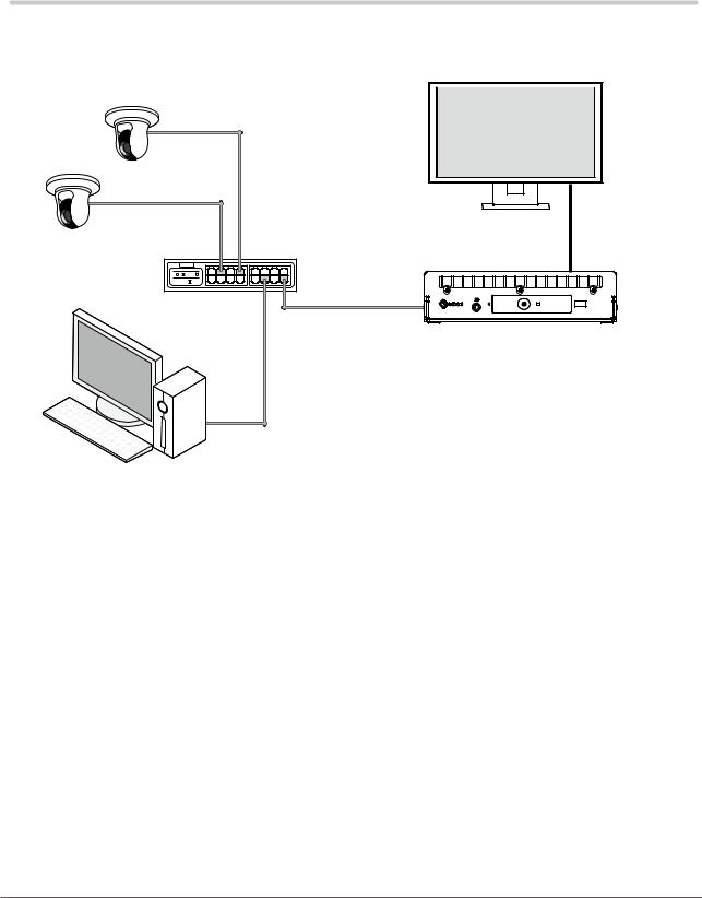
1-2. System Configuration
This system can communicate with network cameras, display video on the monitor that is connected to this product, and operate the network cameras.
Monitor
Network cable
Network camera*1
Network cable
HDMI cable
Network hub*2
Network cable
DX0211-IP
Network cable
PC*2
*1 Up to 48 network cameras can be registered.
*2 Use a network hub that supports PoE+. If the hub does not support the PoE+ standard, network cameras and DX0211-IP must be individually connected to the power supply.
*3 When setting the network cameras using a Web browser, use a computer on the same network as the DX0211IP.
Chapter 1 Product Overview |
5 |

1-3. Supported Network Cameras
This product supports ONVIF Profile S network cameras.
Attention
••Supported network cameras vary depending on the product's software version. Check the software version of the product you are using, then check our website (www.eizoglobal.com) for details on supported network cameras. For information on how to check the software version, refer to “2-2. Setting Screen” (page 10).
••For installing and setting the network cameras, refer to the network camera User’s Manual.
Note
••To verify the connection of a network camera, the image of the network camera can be accessed by specifying the URI. For details, refer to “4-1. Registering the Network Cameras” (page 35).
6 |
Chapter 1 Product Overview |
Chapter 2 Before Configuration
System settings can be made from the screen (application screen) displayed on the monitor connected to the product or from the web browser of a computer connected to the same network.
2-1. Logging In to the System
To configure this product, you need to log in to the system.
Login is allowed only when the level of the user accessing the product is “ADMIN”. Log in to the system according to the following procedure.
Note
••The following user information is set by default. -- Username: “admin”
-- Password: “admin” -- User Level: “ADMIN”
••For information on user settings, refer to “Chapter 6 Management of the User Account” (page 55).
••It is recommended that you log out after completing the setup, so as to prevent a third party from operating the network camera or altering the settings.
••When the Auto Login settings are configured, it is possible to log in to the system without the username and password.
For details, refer to “6-4. Configuring Auto Login Settings” (page 59).
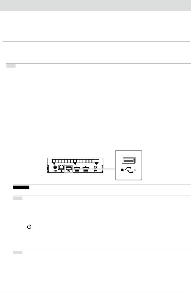
●●Configuring from this product
A USB mouse is required when operating from the application screen. Connect a USB mouse to the USB downstream port of this product.
Attention
•• Adjust the monitor in advance so that the HDMI input can be displayed.
Note
••When connected to a device that has the USB hub function, both the USB mouse and USB keyboard can be used.
••For entering characters, refer to “Entering characters” (page 9).
1. Press on the front of this product.
The power indicator lights up blue and the live image screen is displayed on the monitor connected to this product.
(For information on the live image screen, refer to the “Instruction Manual”.)
Note
•• The power supply is set to “On” by default.
Chapter 2 Before Configuration |
7 |
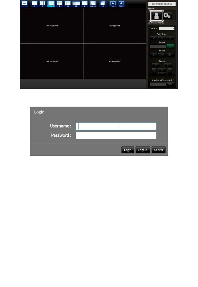
2.Select  (Login) under “System”.
The login screen is displayed.
3.Enter “Username : ” and “Password : ”.
4.Select “Login”.
The display returns to the live image screen.
5.Select  (Settings).
The setting screen is displayed.
8 |
Chapter 2 Before Configuration |

Entering characters
••When entering using a USB keyboard
Typed characters are entered in the text box.
••When entering using a USB mouse
Clicking an item that requires characters to be input, such as a text box, will display a software keyboard. When the focus is moved out of the software keyboard, the software keyboard is hidden.
●●Configuring from a web browser
Attention
••It is recommended you use Internet Explorer 11 as your web browser.
••When configuring from the web browser, the power supply must be connected to this product.
1.Start the web browser of the PC to be used.
2.Enter the following address for access.
Address: http://Address of this product*1
*1 The default address for access is http://192.168.0.150.
The login screen is displayed.
3.Enter a username and a password.
4.Select “OK”.
The setting screen is displayed.
Note
••If you are unable to login, try using the following address. http://address of this product/index.html
Chapter 2 Before Configuration |
9 |
2-2. Setting Screen
The setting screen is comprised of “Basic Information”, “System Settings”, and “Live Image Screen Settings”.
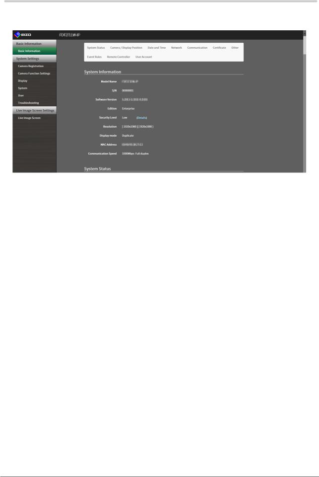
●●Basic Information
Information on various settings of this product is displayed in a list.
Clicking on an item tab at the top of the screen will display each setting item.
System Information
Displays the current status.
••Model Name
••S/N
••Software Version
••Edition
••Resolution
••Display mode
••MAC Address
••Communication Speed
••Security Level (Enterprise Edition only)
System Status / Camera / Display Position / Date and Time / Network / Communication / Certificate / Other / Event Rules / Remote Controller / User Account*1
The current setting status is displayed.
*1 Only available for use if the edition is Enterprise.
●●System Settings
Various settings such as registration of network cameras and system settings are performed.
●●Live Image Screen Settings
Display settings such as changing the live image screen layout are performed.
10 Chapter 2 Before Configuration
Chapter 3 System Settings
Perform settings for the date and time of the system, network settings, and maintenance. These operations can be performed from the application screen or from the web browser.
This chapter explains the procedure using the web browser. However, except for a few functions, the same functions can be used with either method.
3-1. Performing Network Settings
Perform network settings such as IP address, DNS, and NTP.
Attention
••When any one of the IP address settings/IP address/subnet mask/gateway is changed and “Apply” is selected, the warning message “The network settings will be changed.” is displayed.
Select “OK”.
••The same warning message is displayed when the IP address is changed from the web browser. Selecting “OK” will display a message requesting reaccess. Access again using the changed IP address.
1. Select “Network” of “System”.
The “Network” screen is displayed.
Chapter 3 System Settings 11

2.Set the following items.
Network Settings
Item |
|
|
Detail |
Setting range |
IP Setting Method |
|
Select “IP Setting Method”. |
DHCP / Manual |
|
IP Address*1 |
When “Manual” is selected under “IP Setting Method”, “IP |
0.0.0.0 to |
||
Subnet Mask |
|
Address”, “Subnet Mask”, and “Gateway” can be set. |
255.255.255.255 |
|
Gateway*2 |
|
|
|
|
|
Attention |
|
|
|
|
|
|
|
|
••Avoid duplicate IP addresses for devices on the same network.
••If multiple units of this product are connected on the same
network, their IP addresses should be changed. *1 The initial address is “192.168.0.150”.
*2 If the environment does not include a gateway, it is not necessary to set “Gateway”. Either leave it as default setting or set “0.0.0.0”.
DNS Settings
Item |
Detail |
Setting range |
DNS |
(Only when “Manual” is selected under “IP Setting Method” |
Auto / Manual |
|
of “Network Settings”) |
|
|
Set “DNS”. |
|
Primary Server |
When “Manual” is selected under “DNS”, set “Primary |
0.0.0.0 to |
Address |
Server Address” and “Secondary Server Address”. |
255.255.255.255 |
Secondary Server |
|
|
Address |
|
|
NTP Settings
Item |
Detail |
Setting range |
NTP |
Set whether to use the NTP server or not. |
On / Off |
Server Address |
When “On” is selected, set the NTP server address. |
Alphanumerics and |
|
|
symbols |
3.Select “Apply”.
The setting complete screen is displayed.
4.Select “OK”.
12 Chapter 3 System Settings
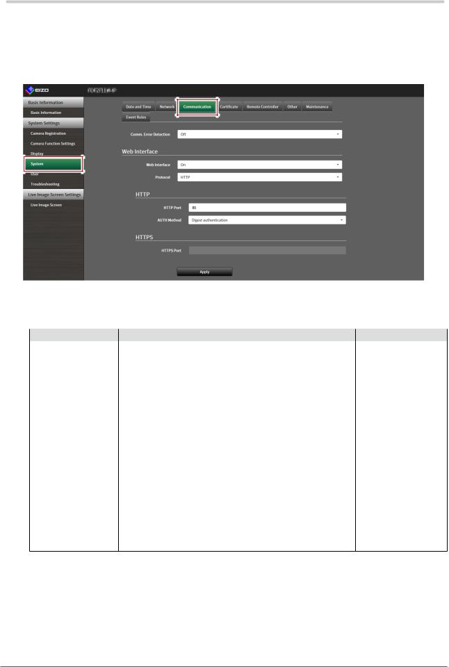
3-2. Performing Communication Settings
The communication settings are used to configure the web interface function and detection of communication errors.
1. Select “Communication” of “System”.
The “Communication” screen is displayed.
2.Set the following items.
Item |
Detail |
Setting range |
Comm. Error Detection Set the message display timing when the reception of video |
On / Off |
|
|
image data stops. |
|
|
On: |
|
|
Within several seconds after the reception of video image |
|
|
data stops, an alert message is displayed in a red box on the |
|
|
live image screen. When communication resumes, the alert is |
|
|
cleared and the video image is displayed again. |
|
|
Off: |
|
|
When approx. 30 seconds have elapsed after the reception |
|
|
of video image data stops, a communication error message is |
|
|
displayed. |
|
Web Interface |
Enables operation and setting of the product over the network |
On / Off*1 |
|
from a web browser. |
|
Protocol |
Select protocol for communication with the web server.*2 |
HTTP / HTTPS*3 / |
|
|
HTTP and HTTPS*3 |
HTTP Port |
Set the HTTP port of the web interface. |
80, 1024 to 65535 |
AUTH Method |
Set the authentication method for the web interface.*4 |
Digest authentication / |
|
|
BASIC authentication |
HTTPS Port |
Set the HTTPS port of the web interface. |
443, 1024 to 65535 |
*1 If “USB Lock” is “On” and “Remote Controller Lock” is “On”, it cannot be set to “Off”.
*2 Depending on the protocol selected, the address may be different when accessing this product from the web browser.
“HTTP”: http://address of this product “HTTPS”: https://address of this product
“HTTP and HTTPS”: can be accessed from either of the above
*3 Can be set when either “Self-Signed Certificate” or “CA-Signed Certificate” is selected in “Certificate”. *4 Cannot be set when “User Account” is “LDAP”.
Chapter 3 System Settings 13

3.Select “Apply”.
The setting complete screen is displayed.
4.Select “OK”.
Attention
••When “Web Interface” is set to “Off”, the settings cannot be configured from the web browser.
••When “Web Interface” is set to “Off” and “Apply” is selected, the following warning message is displayed.
14 Chapter 3 System Settings
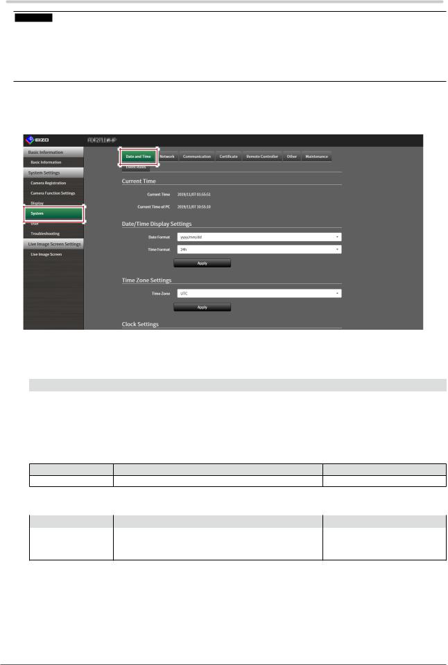
3-3. Setting the Current Date and Time
Attention
••Set the correct dates. Incorrect dates may result in failure of secure communication during certificate validation. If you use SSL for communication with the camera or LDAP setting, avoid the state of power turned off for a long time of period or make sure correct time is set using NTP.
••If secure LDAP communication is not established, you can not login. Reset the account setting using the Reset button.
1. Select “Date and Time” of “System”.
The “Date and Time” screen is displayed.
2.Set the current date and time.
Date/Time Display Settings
Item |
Detail |
Setting range |
Date Format |
Set the date format and time format. |
yyyy/mm/dd, Mmm/dd/yyyy, dd/ |
|
|
Mmm/yyyy, mm/dd/yyyy, dd/ |
|
|
mm/yyyy |
Time Format |
|
24h / 12h |
Time Zone Settings
Item |
|
Detail |
Setting range |
Time Zone |
Set the time zone. |
|
Region / city |
Clock Settings
Item |
Detail |
Setting range |
Procedure*1 |
Select the time setting procedure. |
Manual / Synchronize with PC |
Date and Time |
Set the current time. |
2018/1/1 0:00 to 2035/12/31 |
|
|
23:59 |
*1 This can be set only when displayed on the web browser.
Chapter 3 System Settings 15

3.Select “Apply”.
The setting complete screen is displayed.
4.Select “OK”.
Note
••When “Synchronize with PC” is selected for “Procedure”, the current date and time information of the computer is transmitted to this product.
••If the system is not connected to the power supply for one week or longer, the date and time displayed on this product will become incorrect. If such a situation occurs, reset the date and time.
16 Chapter 3 System Settings
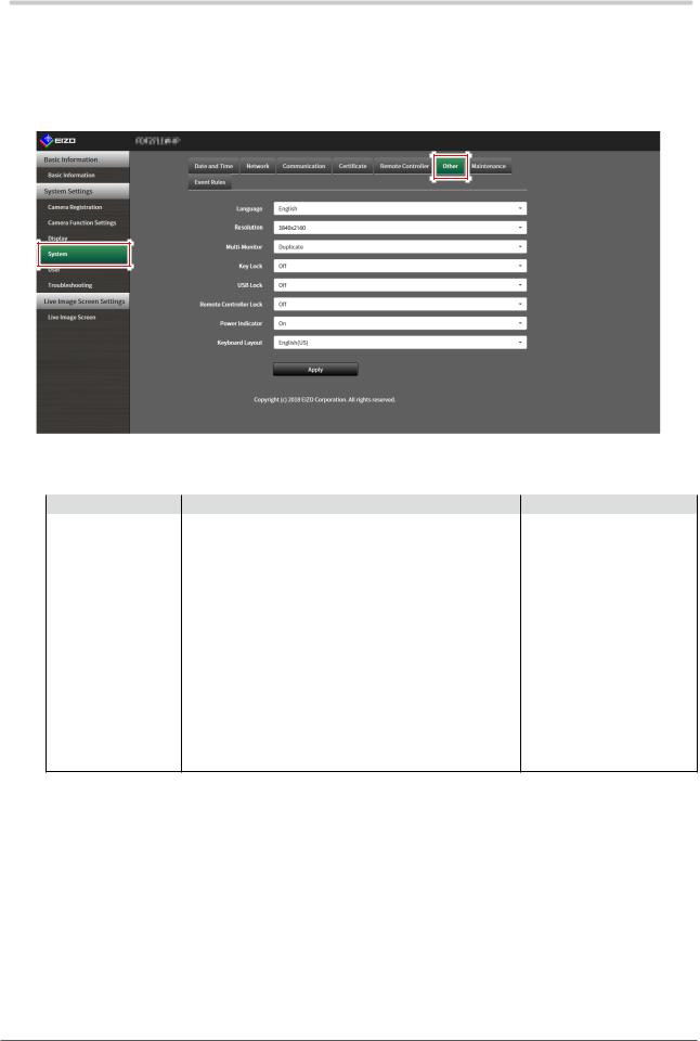
3-4. Other System Settings
Perform the following settings: “Language”, “Resolution”, “Multi-Monitor”, “Key Lock”, “USB Lock”, “Remote Controller Lock”, “Power Indicator”, and “Keyboard Layout”.
1. Select “Other” under “System”.
The “Other” screen is displayed.
2.Set the following items.
Item |
Detail |
Setting range |
Language |
Set the display language of the menu and the setting |
/ English / Deutsch |
|
screen. |
|
Resolution |
Select an output resolution to the monitor. |
1920x1080 / 2560x1440 / |
|
|
3840x2160 |
Multi-Monitor |
Select the method for outputting the signal from the HDMI Single / Extended / Duplicate |
|
|
connector 2. |
|
Key Lock |
Locks operations by the buttons on the front of this |
On / Off |
|
product. |
|
USB Lock*1, 2 |
Locks operations of the USB device. |
On / Off |
Remote Controller |
Lock the operation of the remote control. (A function for |
On / Off |
Lock*1 |
use with models equipped with a remote control) |
|
Power Indicator |
Sets whether to turn the power indicator (blue) on or off |
On / Off |
|
under normal operation. |
|
Keyboard Layout |
Select the keyboard arrangement. |
Japanese / English(US) / |
|
|
English(UK) / German |
*1 This can be set only when displayed on the web browser.
*2 When the setting of “USB Lock” is changed, the product needs to be restarted.
3.Select “Apply”.
The setting complete screen is displayed.
4.Select “OK”.
Chapter 3 System Settings 17
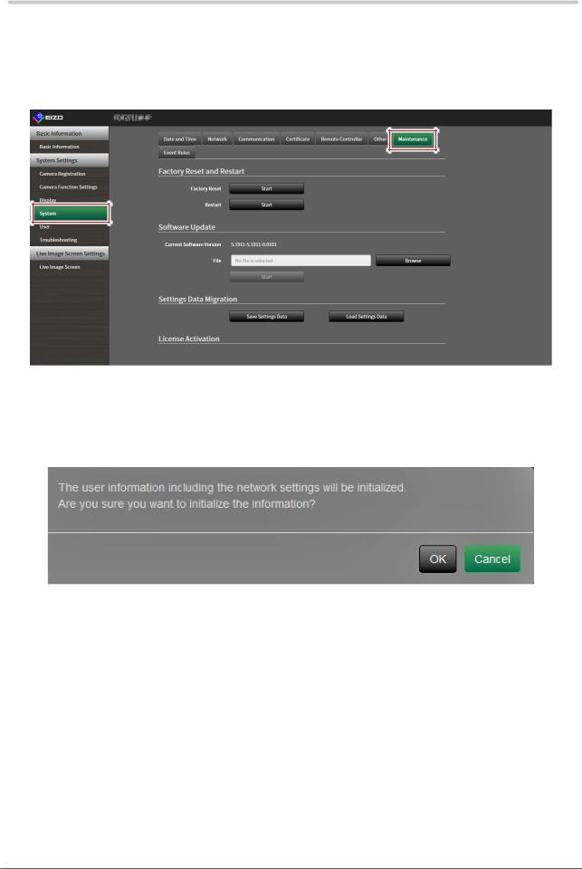
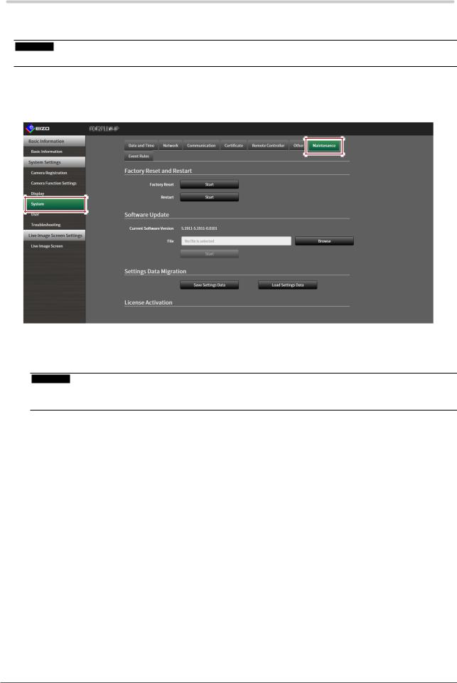
3-5. Initializing the System
All settings are returned to default except for system logs, operation logs, the current time, time zone settings, license activation information, and the software version.
1. Select “Maintenance” of “System”.
The “Maintenance” screen is displayed.
2.Select “Start” under “Factory Reset”.
A confirmation message is displayed.
3.Select “OK”.
18 Chapter 3 System Settings
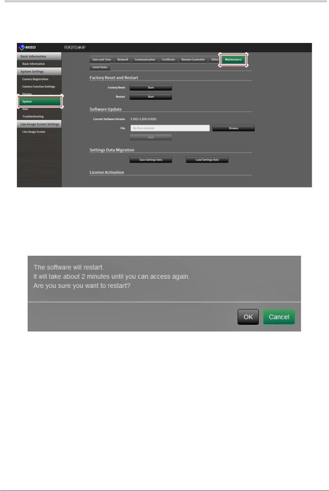
3-6. Restarting the System
1. Select “Maintenance” of “System”.
The “Maintenance” screen is displayed.
2.Select “Start” under “Restart”.
A confirmation message is displayed.
3.Select “OK”.
The system will restart.
Chapter 3 System Settings 19
3-7. Updating Software
The software version can be upgraded. Download the upgrade file from the EIZO website (www. eizoglobal.com) ahead of time.
Attention
•• This function can be used only when using the web browser.
1. Select “Maintenance” of “System”.
The “Maintenance” screen is displayed.
2.Select the upgrade file.
Select “Browse” under “Software Update” and set the file.
Attention
••The software will not be updated if a file is not selected, or a file other than an update file has been selected.
••Update the software only when the power supply is connected to the product.
3.Select “Start”.
A confirmation message is displayed.
20 Chapter 3 System Settings
4.Select “OK”.
A “Software is being updated” message is displayed.
5.Select “OK”.
Note
••It takes approximately five minutes to update the software.
••The red LED blinks while the software is updating.
Chapter 3 System Settings 21
Loading...