


 Loading...
Setup Manual
Important: Please read PRECAUTIONS, this Setup Manual and the User’s Manual stored on the CD-ROM carefully to familiarize yourself with safe and
effective usage. Please retain this manual for future reference.
Installationshandbuch
Wichtig: Lesen Sie die VORSICHTSMASSNAHMEN, dieses Handbuch zur Einrichtung und das Benutzerhandbuch (auf der CD-ROM) aufmerksam durch, um sich mit
der sicheren und effizienten Bedienung vertraut zu machen. Bewahren Sie dieses Handbuch zum späteren Nachschlagen auf.
Manuel d’installation
Important : Veuillez lire attentivement les PRECAUTIONS, ce Manuel d’installation ainsi que le Manuel d’utilisation inclus sur le CD-ROM, afin de vous familiariser avec ce produit et de l’utiliser efficacement et en toute sécurité. Veuillez conserver ce manuel pour référence ultérieure.
安全、有效地使用本产品。请保留本手册、以便今后参考。
Français Deutsch English

Compatible Resolutions/Frequencies
Kompatible Auflösungen/Bildwiederholfrequenzen Résolutions/Fréquences compatibles
This monitor can be connected to a PC through either an analog or digital signal cable. The cable to be used depends on the type of the PC.
For details, refer to "Connecting Cables" and confirm the shape of the connector of the PC. The monitor supports the following resolutions.
Den Monitor können Sie entweder mit einem analogen oder einem digitalen Signalkabel an einen PC anschließen. Welches Kabel Sie verwenden, hängt vom PC ab.
Nähere Informationen dazu finden Sie im Abschnitt „Kabel anschließen“. Achten Sie dabei bitte auch auf die richtige Form der Steckdose am PC.
Der Monitor unterstützt die nachfolgend aufgeführten Auflösungen.
Ce moniteur peut être raccordé à un PC à l’aide d’un câble d’interface analogique ou numérique. Le câble utilisé est fonction du type de PC.
Pour en savoir plus, reportez-vous à la rubrique « Connexion des câbles » puis validez la forme du connecteur du PC. Le moniteur est compatible avec les résolutions suivantes.
“ ”
Analog Input
Resolution |
Display Mode |
Frequency |
Dot Clock |
|
640 |
× 480 |
Apple Macintosh |
67 Hz |
|
640 |
× 480 |
VGA, VESA |
~85 Hz |
|
720 |
× 400 |
VGA TEXT |
70 Hz |
|
800 |
× 600 |
VESA |
~85 Hz |
|
832 |
× 624 |
Apple Macintosh |
75 Hz |
|
1024 × 768 |
VESA |
~85 Hz |
150 MHz |
|
1152 × 864 |
VESA |
75 Hz |
(Max.) |
|
1152 × 870 |
Apple Macintosh |
75 Hz |
|
|
1280 × 960 |
VESA |
60 Hz |
|
|
1280 × 960 |
Apple Macintosh |
75 Hz |
|
|
1280 |
× 1024 |
VESA |
~75 Hz |
|
1680 × 1050* |
VESA CVT, VESA CVT RB |
60 Hz |
|
|
Digital Input
Resolution |
Display Mode |
Frequency |
Dot Clock |
||
640 |
× 480 |
VGA |
60 Hz |
|
|
720 |
× 400 |
VGA TEXT |
70 Hz |
|
|
800 |
× 600 |
VESA |
60 Hz |
120 MHz |
|
1024 × 768 |
VESA |
60 Hz |
|||
(Max.) |
|||||
1280 × 960 |
VESA |
60 Hz |
|||
|
|||||
1280 |
× 1024 |
VESA |
60 Hz |
|
|
1680 × 1050 * |
VESA CVT RB |
60 Hz |
|
||
*Recommended resolusion (Set this resolution). When displaying the wide format input signal, a graphics board in conformance with VESA CVT standard is required.
*Empfohlene Auflösung (diese Auflösung festlegen). Zur Anzeige des Eingangssignals für das Breitbild ist eine Grafkkarte erforderlich, die die Anforderungen des Standards VESA CVT erfüllt.
*Résolution recommandée (Réglez votre appareil sur cette résolution). Lors de l’affchage du signal d’entrée format large, une carte vidéo conforme à la norme VESA CVT est requise.
*( ) VESA CVT

Checking Package Contents
When removing the monitor from its packaging, remove accessories first, and then lift the monitor out gently. Contact your local dealer if any items are missing or damaged.
The package contains the following items.
Note
•Do not throw out the packaging (box and protective packaging). Keep it in a safe location. It will be required when sending the unit in for repairs.
• ColorNavigator Quick Reference |
• Setup Manual (this manual) |
• Limited warranty |
|
• Recycling Information |
• Mounting Screws (M4 x 12, 4 pcs) |
• PRECAUTIONS |
|
• EIZO LCD Utility Disk (CD-ROM) |
|
||
• |
Calibration software |
• User’s Manuals (PDF format) |
|
|
ColorNavigator |
ColorEdge CG222W |
etc. |
|
|
ColorNavigator |
|
|
Hood |
|
|
Cleaning kit |
|
|
|
“ScreenCleaner” |
|
|
|
Analog signal cable |
Power cord |
(FD-C16) |
Digital signal cable |
Monitor |
EIZO USB cable |
|
||
|
(MD-C93) |
|
(FD-C39) |
|
|
|
|
Adjustment
Certificate
Adjustment Certificate
This sheet is attached to the “PAD-LCD”
LCD panel protection pad.
Français Deutsch English
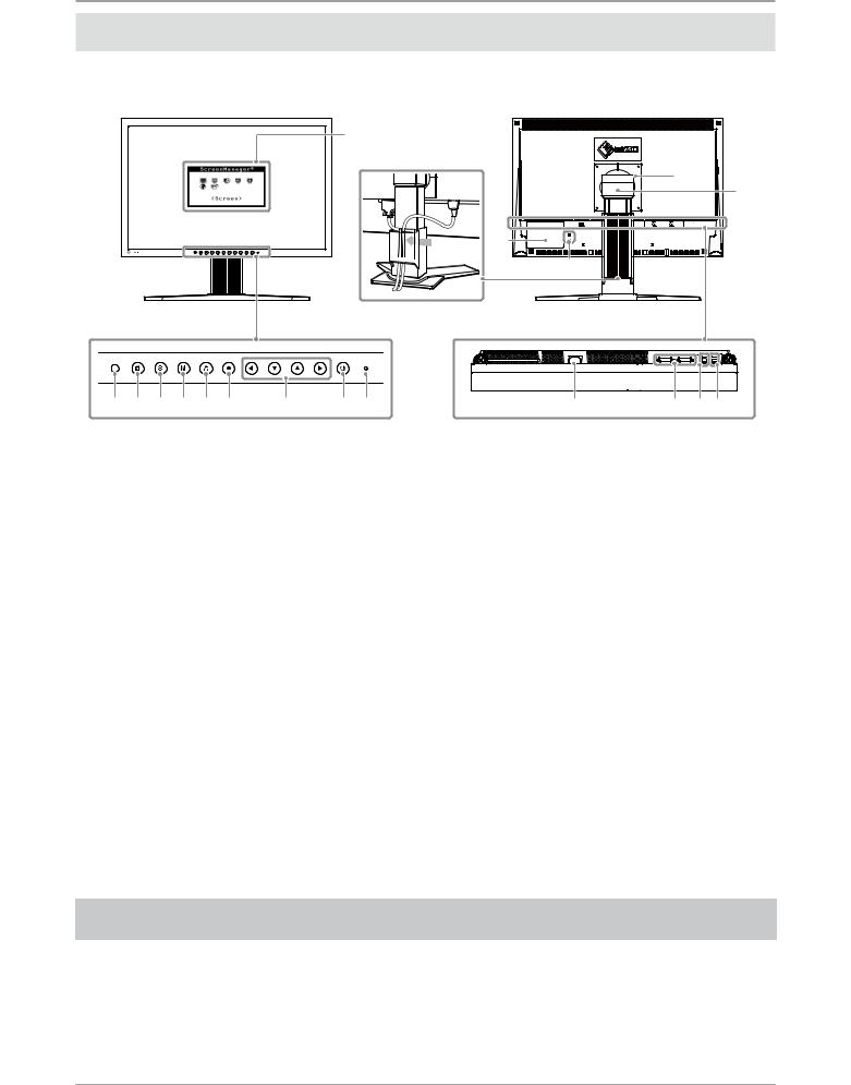
Controls and Functions
Display and adjustment buttons are located on the front of the monitor, and connectors are located on the rear. The name and functions of the buttons and connectors are described below.
|
|
|
|
|
|
|
|
Adjustment menu |
|
|
|
|
|
|
|
|
|
|
|
|
(ScreenManager ® *) |
|
|
|
|
|
|
|
|
|
|
|
|
|
|
|
B |
|
|
|
|
|
|
|
|
|
|
|
|
|
15 |
|
|
|
|
|
|
|
|
|
A |
|
|
|
|
|
|
|
|
|
|
|
|
16 |
10 |
|
|
|
|
|
|
|
|
|
|
|
|
|
|
|
1 |
2 |
3 |
4 |
5 |
6 |
7 |
8 |
9 |
|
11 |
12 |
13 14 |
1 |
Sensor |
Detects ambient brightness. BrightRegulator function. |
|
|
For details, refer to the User’s Manual on the CD-ROM. |
|
|
|
2 |
Adjustment Lock button |
This function locks the buttons to retain the status adjusted or set once. |
|
|
|
3 |
Input Signal Selection button |
Switches input signals for display when two PCs are connected to the monitor. |
|
|
|
4 |
Mode button |
Allows you to switch the display mode. |
|
|
|
5 |
Auto button |
Performs the function to adjust the screen automatically. (analog input only) |
|
|
|
6 |
Enter button |
Displays the Adjustment menu, determines an item on the menu screen, and |
|
|
saves values adjusted. |
|
|
|
7 |
Control buttons |
Chooses an adjustment item or increases/decreases adjusted values for |
|
(Left, Down, Up, Right) |
advanced adjustments using the Adjustment menu. |
|
|
|
8 |
Power button |
Turns the power on or off. |
|
|
|
9 |
Power indicator |
Indicates monitor’s operation status. |
|
|
Blue: Operating Orange: Power saving Off: Power off |
|
|
Flashing blue (2 times for each): When the timer is set for ColorNavigator, |
|
|
notifes that a recalibration is required (for CAL mode or EMU mode). |
|
|
|
10 |
Security lock slot |
Complies with Kensington’s MicroSaver security system. |
|
|
|
11 |
Power connector |
Connects the power connector. |
|
|
|
12 |
Input signal connectors |
DVI-I Connector x 2 |
|
|
|
13 |
USB port (Up) |
Connects the USB cable in order to use the provided software. For how to use it, |
|
|
refer to the User’s Manual on the CD-ROM. |
|
|
|
14 |
USB port (Down) |
Connects a peripheral USB device. |
|
|
|
15 |
Stand |
Used to adjust the height and angle of the monitor screen. |
|
|
|
16 |
Cable holder |
Covers the monitor cables. |
|
|
|
A |
Caution Statements |
The equipment must be connected to a grounded main outlet. |
|
|
|
B |
Caution Statements |
Caution Risk of electric shock. Do not open. |
|
|
|
* ScreenManager ® is an EIZO’s nickname of the Adjustment menu. (For how to use ScreenManager, refer to the User’s Manual on the CD-ROM.)
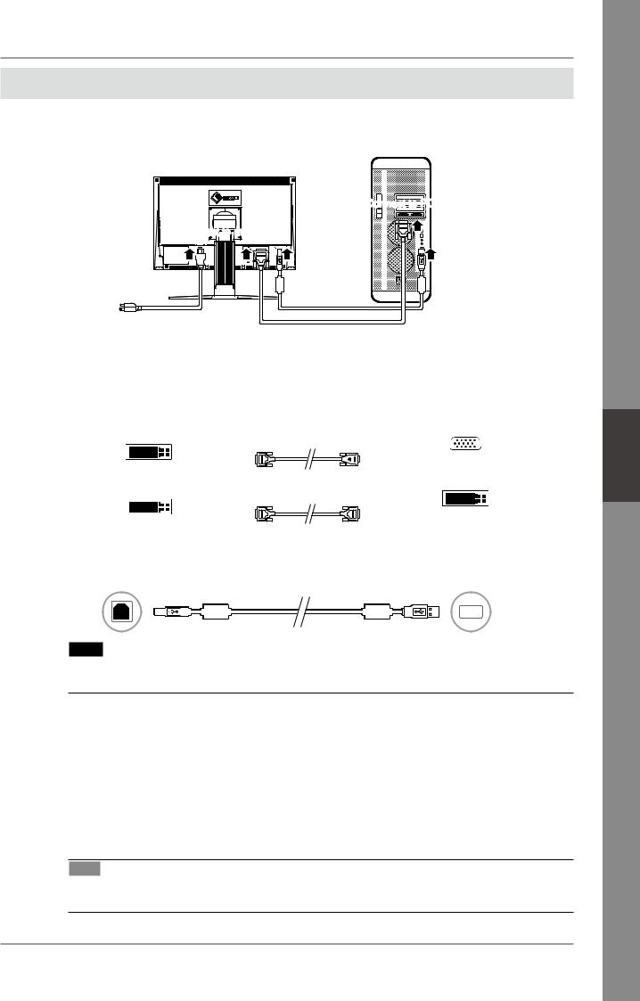
Connecting Cables
Connect the monitor to the PC. Turn the monitor, the PC, and all peripheral devices off before connecting the cables. For details, refer to the supplied CD-ROM.
Connect to monitor
Power cord |
Connect to PC |
USB cable
Connect to power outlet
Digital/Analog signal cable
1 Connect the monitor to the PC with a signal cable that matches the connectors.
After connecting the cable connectors, tighten the screws of the connectors to secure the coupling.
Connectors on the monitor |
|
|
|
|
|
cable |
Connectors on the PC |
|||||||||||||
DVI-I |
|
[Analog signal cable] |
|
|
|
|
|
|||||||||||||
FD-C16 Analog connection |
|
|
|
|
|
|||||||||||||||
|
|
|
|
|
|
|
|
|
|
|||||||||||
|
|
|
|
|
|
|
|
|
|
|
|
|
|
|
|
|
|
|
|
|
|
|
|
|
|
|
|
|
|
|
|
|
|
|
|
|
|
|
|
|
|
|
|
|
|
|
|
|
|
|
|
|
|
|
|
|
|
|
|
|
|
|
|
|
|
|
|
|
|
|
|
|
|
|
|
|
|
|
|
|
|
|
|
DVI-I |
|
|
|
[Digital signal cable] |
|
|
|
|
|
|||||||||||
FD-C39 Digital connection |
|
|
|
|
|
|||||||||||||||
|
|
|
|
|
|
|
|
|
|
|
|
|
|
|
|
|
|
|
|
|
|
|
|
|
|
|
|
|
|
|
|
|
|
|
|
|
|
|
|
|
|
|
|
|
|
|
|
|
|
|
|
|
|
|
|
|
|
|
|
|
|
|
|
|
|
|
|
|
|
|
|
|
|
|
|
|
|
|
|
|
|
|
|
2 Connect the monitor to the PC with the USB cable.
Connect to the monitor |
|
|
|
|
|
|
|
|
|
|
|
|
|
|
|
|
|
|
|
|
|
|
Connect to the PC |
|||||||||||||
|
|
|
|
|
|
|
|
|
|
|
|
|
|
|
|
|
|
|
|
|
|
|
|
|
|
|
|
|
|
|
|
|
|
|
|
|
|
|
|
|
|
|
|
|
|
|
|
|
|
|
|
|
|
|
|
|
|
|
|
|
|
|
|
|
|
|
|
|
|
|
|
|
|
Note
•The USB cable is required for calibration. Be sure to connect the monitor and PC with the USB cable.
3 Plug the power cord into a power outlet and the power connector on the monitor.
4 Press  to turn on the monitor.
The monitor’s Power indicator lights up blue.
5 Turn on the PC.
The screen image appears.
If an image does not appear, refer to "No-Picture Problem" for additional advice.
Tips
•When the PC and the monitor are turned off, monitor power is turned off completely, even though the power cord is still connected to the monitor.
Français Deutsch English
Setting Resolution
When you connect the monitor to the PC and find that the resolution is improper, or when you want to change the resolution, follow the procedure below.
Recommended resolution: 1680 dots x 1050 lines (60 Hz)
MacOS X
1 |
Select "System Preferences" from the Apple menu. |
2 |
When the "System Preferences" dialog is displayed, click "Displays" for "Hardware". |
3 |
On the displayed dialog, select the "Display" tab and select desired resolution in the "Resolutions" field. |
4 |
Your selection will be reflected immediately. When you are satisfied with the selected resolution, close the |
|
window. |
Windows XP |
|
1 |
Right-click the mouse anywhere on the desktop except for icons. |
2 |
From the displayed menu, click "Properties". |
3 |
When the "Display Properties" dialog is displayed, click the "Settings" tab and select desired resolution for |
|
"Screen resolution" under "Display". |
4 |
Click the "OK" button to close the dialog. |
Windows Vista |
|
1 |
Right-click the mouse anywhere on the desktop except for icons. |
2 |
From the displayed menu, click "Personalize". |
3 |
On the "Personalization" window, click "Display Settings". |
4 |
On the "Display Settings" dialog, select the "Monitor" tab and select desired resolution in the |
|
"Resolution" field. |
5 |
Click the "OK" button. |
6 |
When a confirmation dialog is displayed, click "Yes". |
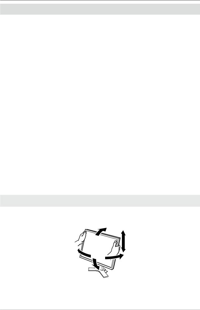
Adjusting the Monitor Height and Angle
The angle and height of the monitor can be adjusted.
Adjust the screen height and angle, tilt and swivel the screen to the best condition for working.
How to Install the Hood
CAUTION
Do not carry the monitor with the hood |
Do not place any objects on the hood. |
attached. |
If the hood falls or slips off or the monitor falls over, it |
While carrying the monitor, the hood may fall or slip |
may result in injury or equipment damage. |
off, which may result in injury or equipment damage. |
|
|
|
Close the open/close cover until it contacts the |
Do not rotate the monitor into the portrait |
stopper. |
position. |
If the cover is not closed properly, the ventilation slots |
Doing so may cause the hood to slip off, which may |
on the monitor will be covered and proper airflow |
result in injury or equipment damage. |
will be prevented. This may cause overheating inside |
|
the monitor and may result in fire, electric shock, or |
|
equipment damage. |
|
|
|
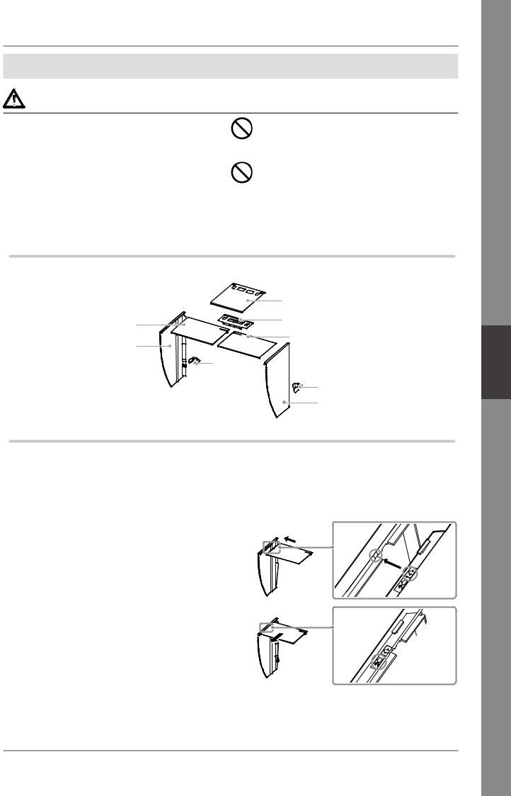
Package Contents
Check that all the following items are included in the packaging box.
|
Open/close cover |
Top cover |
Metal fitting |
|
|
Left cover |
Top cover |
|
|
|
Hook |
|
Hook |
|
Right Cover |
Assemble the left and right hoods
Assemble the hoods in the direction of the arrows marked on the insertions on the top covers of the right and left hoods.
1 Hold the left hood’s left and top covers with the sides with the anti-reflective sheet facing inward.
2 Connect the top and left covers by aligning the arrow (1  ) on the top
cover’s insertion with the two lines on the left cover’s insertion slot.
3 Slide the top cover in the direction shown by the arrow (2  ).
).
Assembly of the left hood is complete.
4 Assemble the right hood in the same way.
Français Deutsch English
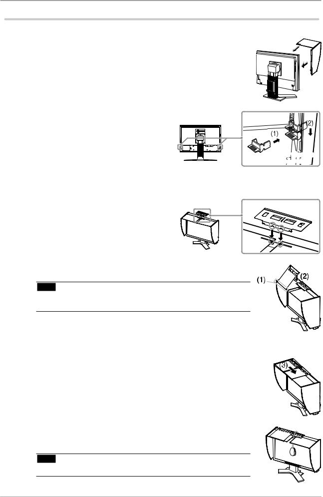
Attach the left and right hoods to the monitor
Be sure to install the second hood only after the other hood is firmly attached with hook.
1
2
Attach the top side of the left hood to the monitor first and then securely fit the left side of the hood in order to fix the hood to the monitor.
Insert the hook into the upper hole on
the hood (1) and slide it down along the projection on the back side of the monitor (2).
Insert into the upper hole
3
4
5
Attach the right hood in the same way.
Check the locations of the depressions in the fitting and insert the fitting into the left and right hoods by aligning those depressions with the projections
( ) in the grooves on the right and left hoods.
Attach the open/close cover to the left hood.
Note
•Do not attach the open/close cover to the right hood. Doing so prevents the cover from closing.
6 Place the open/close cover on the top of the left hood (without contacting the metal fitting) from front (1) to back (2).
7 Slide the open/close cover to the right (3) until it contacts the stopper on the metal fitting.
8 When performing calibration, slide the open/close cover to the left in order to attach the sensor.
Note
• The open/close cover does not slide onto the right cover.
Prepare for the Monitor Calibration
For details regarding the calibration procedure, refer to the ColorNavigator User’s Manual on the CD-ROM.
Installing ColorNavigator
1 Uninstall any measurement driver software that may be installed on the PC.
2 Insert the EIZO LCD Utility Disk into the PC’s CD/DVD drive.
3 MacOS X
Click the CD-ROM icon on the desktop, and then click [Start Menu] in the displayed window.
Windows XP
A menu will open automatically. If the menu does not open automatically, double-click the "Launcher.exe" icon in the CD-ROM.
Windows Vista
When using Windows Vista, a "User Account Control" dialog may appear by clicking the "Launcher.exe" icon. In this case, click [Continue] to open the menu.
4 Click "Install ColorNavigator" in the EIZO LCD Utility’s initial screen. Follow the instructions to complete the installation.
Note
•Measurement driver software is automatically installed during ColorNavigator installation. It is not necessary to install the driver software that is supplied with your measurement device.
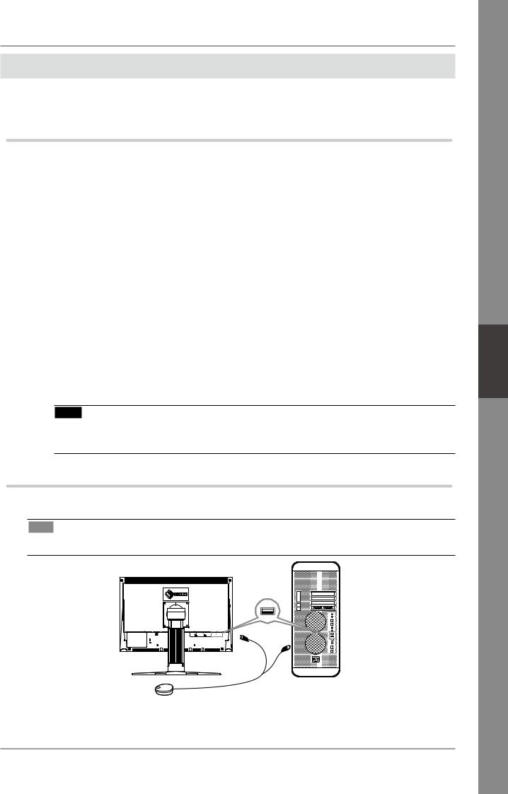
Connecting the measurement device
Connect an optional measurement device which you purchased separately.
Tips
• Refer to the User’s Manual for the measurement device in regard to connection.
Either OK |
Measurement Device
Français Deutsch English
How to calibrate the monitor
Startup ColorNavigator and calibrate the monitor. Follow the instructions displayed on the screen and in the ColorNavigator Quick Reference.
For details, refer to the "ColorEdge ColorNavigator User’s Manual" on the EIZO LCD Utility Disk.
Note
•When calibrating the monitor, the monitor and the PC must have had the power on for at least 30 minutes. Be sure to calibrate the monitor after the power has been turned on for 30 minutes or more.
Tips
• For detailed information about calibration, visit http://www.eizo.com.
You can use the mode button on the front panel to switch the monitor to one of the four image adjustment modes (sRGB mode, Custom mode, CAL mode, and EMU mode) suitable for the displayed image.
No-Picture Problem
If no picture is displayed on the monitor even after the following remedial action is taken, contact your local dealer.
Symptom |
Status |
Possible cause and remedy |
|
|
|
No picture |
Power indicator does not light |
• Check whether the power cord is correctly |
|
up. |
connected. |
|
|
• If the problem persists, turn off the monitor, |
|
|
and then turn it on again a few minutes later. |
|
|
• Press . |
|
|
|
|
Power indicator lights blue. |
• Set high values for Gain RGB levels. |
|
|
|
|
Power indicator lights orange. |
• Switch the input signal with . |
|
|
|
|
|
• Press a key on the keyboard or click the mouse. |
|
|
|
|
|
• Turn on the PC. |
|
|
|
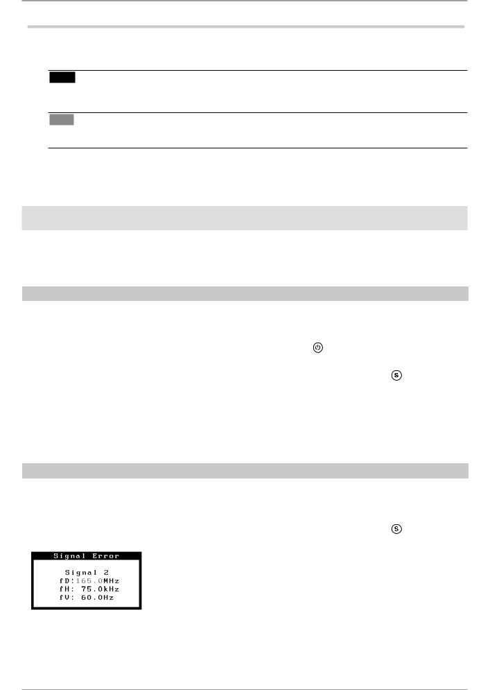
2. Check the error message that remains on the screen.
These messages appear when the input signal is incorrect even if the monitor is functioning.
Symptom |
Status |
Possible cause and remedy |
|
|
|
|
The input signal is not received. |
• Check whether the PC is turned on. |
|
|
|
|
|
• Check whether the signal cable is properly |
|
|
connected to the PC. |
|
|
|
|
|
• Switch the input signal with . |
|
|
|
|
The signal frequency is outside |
• Restart the PC. |
|
the specifcation. Incorrect |
• Change the mode to an appropriate mode |
|
signal frequency is shown in |
using the graphics board’s utility software. |
|
red. |
Refer to the manual of the graphics board for |
|
|
details. |
|
|
|
Überprüfen des Verpackungsinhalts
Wenn Sie den Monitor aus der Verpackung nehmen, entfernen Sie zuerst die Zubehörteile, und heben Sie anschließend den Monitor vorsichtig heraus.
Kontaktieren Sie bitte Ihren Händler, wenn Teile fehlen oder beschädigt sind. Die Verpackung enthält folgende Teile.
Hinweis |
•Werfen Sie die Verpackung nicht weg (Schachtel und Schutzverpackung). Bewahren Sie sie an einem sicheren Ort auf. Wenn das Gerät zur Reparatur eingesandt werden muss, wird die Verpackung wieder benötigt.
• ColorNavigator-Kurzanleitung |
• Installationshandbuch |
• Beschränkte Garantie |
||
|
(das vorliegende Handbuch) |
|
|
|
• Informationen zum Thema Recycling |
• Befestigungsschrauben |
• VORSICHTSMASSNAHMEN |
||
|
(M4 x 12, 4 Stck.) |
|
|
|
• CD-ROM mit EIZOs LCD Utility Disk |
|
|
||
• Kalibirierungssoftware |
• Benutzerhandbücher (im PDF-Format) |
|||
ColorNavigator |
ColorEdge CG222W |
usw. |
||
|
|
ColorNavigator |
||
Abdeckhaube |
|
|
|
|
Reinigungsset |
|
|
|
|
„ScreenCleaner“ |
|
|
|
|
Analoges Signalkabel |
Netzkabel |
(FD-C16) |
Digitales Signalkabel |
Monitor |
EIZO USB-Kabel |
|
||
|
(MD-C93) |
|
(FD-C39) |
|
|
|
|
Justagezer-
tifizierung
Justagezertifizierung
Dieses Blatt ist am Displayschutz des „PAD-LCD“ LCD-Displays befestigt.
Français Deutsch English
Loading...