

Page 1

Bedienungsanleitung
Metall- Bohr- und Fräsmaschine
t
Operating Instructions
Metal Drilling and Routing Machine
p
Mode dʼemploi
perceuse et fraiseuse pour métal
C
Istruzioni per lʼuso
Trapanatrice e fresatrice per metalli
m
Manual de instrucciones
Taladro-fresadora de metal
A
Használati utasítás
Fém-fúró- és marógép
q
Käyttöohje
Metallipora- ja jyrsinkone
U
Bruksanvisning
Metall-borr- och fräsmaskine
B
Upute za uporabu
f
bušilice i glodalice za metal
P
Instrukcja obsługi
Wiertarko - frezarka stołowa
Art.-Nr.: 42.530.02 I.-Nr.: 01017
BT-MR 550
Anleitung_BT_MR_550_SPK7:_ 18.12.2007 15:44 Uhr Seite 1
Page 2
2
1
2 3
3
14
20
10
9
12
10
11
21
c
0
I
23
13
16
4
8
1
6
16
15
15
b
6
a
7
5
2
Anleitung_BT_MR_550_SPK7:_ 18.12.2007 15:44 Uhr Seite 2
Page 3

3
7
4
6
5
8 9
19
19
27
17
17
15
14
18
28
19
4
9
14
28
5
27
Anleitung_BT_MR_550_SPK7:_ 18.12.2007 15:44 Uhr Seite 3
Page 4
4
10 11
22
10
10
22
11
13
12 13
20
24
23
12
14
25
26
Anleitung_BT_MR_550_SPK7:_ 18.12.2007 15:44 Uhr Seite 4
Page 5

5
“WARNUNG - Zur Verringerung des Verletzungsrisikos Bedienungsanleitung lesen”
Netzstecker ziehen!
Achtung! Arbeiten an elektrischen Anlagen dürfen nur von einer Elektrofachkraft durchgeführt
werden!
Achtung! Wählhebel für Drehzahlbereich nur im Stillstand betätigen!
Achtung! Vor dem Einschalten muss sich der klappbare Spannfutterschutz in
herausgeklappter Position befinden!
Tragen Sie eine Schutzbrille.
Während der Arbeit entstehende Funken oder aus dem Gerät heraustretende Splitter, Späne
und Stäube können Sichtverlust bewirken.
D
Anleitung_BT_MR_550_SPK7:_ 18.12.2007 15:44 Uhr Seite 5
Page 6

6
D
Achtung!
Beim Benutzen von Geräten müssen einige
Sicherheitsvorkehrungen eingehalten werden, um
Verletzungen und Schäden zu verhindern. Lesen Sie
diese Bedienungsanleitung deshalb sorgfältig durch.
Bewahren Sie diese gut auf, damit Ihnen die
Informationen jederzeit zur Verfügung stehen. Falls
Sie das Gerät an andere Personen übergeben
sollten, händigen Sie diese Bedienungsanleitung
bitte mit aus. Wir übernehmen keine Haftung für
Unfälle oder Schäden, die durch Nichtbeachten
dieser Anleitung und den Sicherheitshinweisen
entstehen.
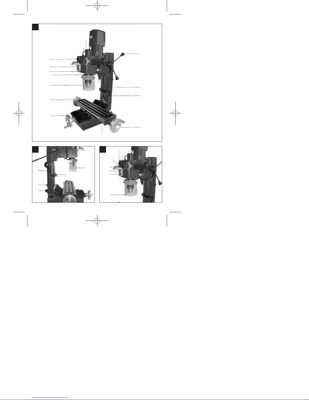
1.Gerätebeschreibung (Bild 1-4)
1. Fräskopf
2. Kreuztisch
3. Maschinensäule
4. Arbeitsspindel
5. Getriebehebel
6. Drehzahlwahlschalter
7. Stellrad für Feinvorschub
8. Ein- / Ausschalter
9. Zahnkranzbohrfutter
10. Handkurbel für Querschlitten
11. Handkurbel für Längsschlitten
12. Tiefenanschlag
13. Befestigungsmutter für Neigungsverstellung
14. Drehkreuz
15. Spindelabdeckung
16. Klappbarer Späneschutz
2. Lieferumfang
Bohr-, Fräsmaschine
Bohrfutterschlüssel
Hakenschlüssel
Fixierstift
Werkzeug
3. Bestimmungsgemäße Verwendung
Diese Maschine ist zum Bohren, Tiefenfräsen und
Stirnfräsen von kleinen Werkstücken (max.
Abmessungen: 300 mm x 200 mm x 200 mm)
aus Metall, Kunststoff oder ähnlichen Materialien
bestimmt . Mit dem serienmäßigen Zahnkranzbohrfutter dürfen nur Bohr- und Fräswerkzeuge mit einem
zylindrischen Schaft von max. 16mm verwendet
werden. Bei der Bearbeitung von Metall (ST37) sollte
der Werkzeugdurchmesser nicht mehr als 13mm
betragen. Es ist zudem auch möglich Werkzeuge mit
kegeligem Schaft (MK3) direkt in der Arbeitsspindel
aufzunehmen. Diese Bohr-, Fräsmaschine ist nur für
den Hausgebrauch geeignet und darf nicht für den
industriellen Einsatz verwendet werden. Die
Maschine darf nur nach ihrer Bestimmung verwendet
werden. Jede weiter darüber hinausgehende Verwendung ist nicht bestimmungsgemäß.
Für daraus hervorgehende Schäden oder Verletzungen aller Art haftet der Benutzer bzw. Bediener
und nicht der Hersteller. Bestandteil der bestimmungsgemäßen Verwendung ist auch die Beachtung
der Sicherheitshinweise sowie die Montageanleitung
und Betriebshinweise in der Bedienungsanleitung.
Personen, die Maschine bedienen und warten,
müssen mit dieser vertraut und über mögliche
Gefahren unterrichtet werden. Darüber hinaus sind
die gelten Unfallverhütungsvorschriften genauestens
einzuhalten. Sonstige allgemeine Regeln in
arbeitsmedizinischen und sicherheitstechnischen
Bereichen sind zu beachten.
Bitte beachten Sie, dass unsere Geräte bestimmungsgemäß nicht für den gewerblichen, handwerklichen oder industriellen Einsatz konstruiert wurden.
Wir übernehmen keine Gewährleistung, wenn das
Gerät in Gewerbe-, Handwerks- oder Industriebetrieben sowie bei gleichzusetzenden Tätigkeiten eingesetzt wird.
Veränderungen an der Maschine schließen eine
Haftung des Herstellers und daraus entstehende
Schäden gänzlich aus. Trotz bestimmungsmäßiger
Verwendung können bestimmte Restrisikofaktoren
nicht vollständig ausgeräumt werden. Bedingt durch
Konstruktion und Aufbau der Maschinen können
folgende Punkte auftreten.
Berührung des Backenfutters in nicht
abgedeckten Bereich.
Eingreifen in rotierende Teile ( Verletzungsge-
fahr )
Wegschleudern von Werkstücken und
Werkstückteilen.
Gesundheitsschädliche Kühl- und Schmiermittel.
Achten Sie auf umweltgerechte Entsorgung.
Berührung rotierender Bauteile im nicht abge-
deckten Bereich. Verletzungsgefahr!
Achtung Verletzungsgefahr! Den Backenfutter-
schlüssen immer sofort wieder Abziehen und
niemals stecken lassen!
Verletzungsgefahr durch das nicht im Einsatz be-
findliche Fräswerkzeug.
Anleitung_BT_MR_550_SPK7:_ 18.12.2007 15:44 Uhr Seite 6
Page 7

7
D
Augenverletzungen durch wegfliegenden
Spänen und anderen Splitter. Tragen Sie
unbedingt eine Schutzbrille!
4. Wichtige Hinweise
Bitte lesen Sie vor der Inbetriebnahme die Gebrauchsanweisung sorgfältig durch und
beachten Sie die Sicherheitshinweise. Machen
Sie sich abhand dieser Gebrauchsanweisung mit
dem Gerät, dem richtigen Gebrauch sowie den
Sicherheitshinweisen vertraut. Bewahren Sie die
Gebrauchsanweisung immer so auf, dass sie
dem Bediener jederzeit zugänglich ist.
Das Tragen einer persönlichen
Schutzausrüstung ist bei allen Arbeiten mit der
Maschine unbedingt erforderlich.
Tragen Sie zur Vermeidung von Augenverletz-
ungen immer eine Schutzbrille
Tragen sie unbedingt ein Haarnetz oder eine ge-
eignete Arbeitsmütze, wenn Sie lange Haare
haben.
Tragen Sie enganliegende Arbeitskleidung.
Das rotierende Werkzeug könnte Ärmel o. a. er-
fassen.
Benutzen Sie zum Entfernen von Spänen einen
geeigneten Spänehacken. Niemals Späne mit
bloßer Hand entfernen.
Bei ausgeschalteter Maschine entfernen Sie
Späne am besten mit einem Handfeger oder
einem Pinsel.
Das Arbeiten mit der Maschine ist nur Personen
über 18 Jahren gestattet, die mit dem Umgang
der wirkungsweise der Maschine vertraut sind.
Jugendlichen zwischen 16 und 18 Jahren ist das
Arbeiten nur unter Aufsicht eines Erwachsenen
gestattet.
Überprüfen Sie vor Arbeitsbeginn die korrekte
Funktion der Schutzeinrichtung
Überlasten Sie die Maschine nicht. Sie arbeiten
besser und sicherer im angegebenen Leistungsbereich.
Benutzen Sie das richtige Werkzeug und achten
Sie drauf, dass die Werkzeuge (Drehmeißel,
Bohrer) nicht stumpf oder abgebrochen sind.
Kabel immer hinten von der Maschine
wegführen. Schützen Sie das Kabel vor Hitze, Öl
und scharfen Kanten.
Ziehen Sie den Netzstecker bei Reparaturen und
Wartungsarbeiten und wenn Sie die Maschine
nicht benutzen.
Arbeiten an elektrischen Einrichtungen dürfen
nur von einer Elektrofachkraft vorgenommen
werden. Es dürfen nur Orginalteile verwendet
werden.
Saubere Arbeitsplätze erleichtern das Arbeiten.
Achten sie darauf, was Sie tun. Gehen Sie mit
Vernunft an die Arbeit.
Achten Sie darauf, dass der Unterbau das Ge-
wicht der Maschine tragen kann und ausreichend
stabil ist, damit beim Bearbeiten keine Schwingungen auftreten können.
Zum Schutz vor Korrosion sind alle blanken Teile
der Maschine werkseitig stark eingefettet. Reinigen Sie die Maschine vor der Inbetriebnahme mit
einem geeigneten umweltfreundlichen Reinigungsmittel.
Achtung! Schließen Sie die Schutzabdeckung
für das Backenfutter bevor Sie die Maschine einschalten.
Mit der Maschine dürfen keine
gesundheitsgefährdenden oder
Stauberzeugenden Materialien, wie z.B. Holz,
Teflon etc. bearbeitet werden.
Benutzen Sie die Maschine nicht in der Nähe
von brennbaren Flüssigkeiten oder Gasen.
Verwenden Sie die Maschine nur in geeigneten
Räumen und setzen Sie die Maschine nicht
feuchten oder nassen Umgebungen aus.
Sorgen Sie beim arbeiten für gute Beleuchtung.
Benutzen Sie das Kabel nicht um den Stecker
aus der Steckdose zu ziehen.
Achten Sie darauf, dass beim Arbeiten das
Werkstück fest eingespannt ist. Werkstück
immer in einem Maschinenschraubstock oder mit
Hilfe von Spannpratzen festspannen.
Verwenden Sie nur scharfe und saubere
Werkzeuge.
Schalten Sie die Maschine bei gefährlichen
Situationen oder technischen Störungen sofort
aus und ziehen Sie den Netzstecker!
Bei Beschädigungen darf mit der Maschine nicht
mehr gearbeitet werden und es muss der
Netzstecker gezogen werden!
Achtung! Es dürfen nur vom Hersteller freige-
gebene Einsatzwerkzeuge und Zubehör verwendet werden. Die Verwendung von nicht freigegebenen Teilen kann eine Verletzungsgefahr für
Sie bedeuten.
Halten Sie Ihren Arbeitsbereich sauber und in
Ordnung. Unordnung im Arbeitsbereich kann
Unfälle verursachen.
Schutzbrille tragen. Bei Arbeiten mit starker
Staubbildung muss außerdem eine Gesichtsbzw. Staubmaske verwendet werden.
Futterschlüssel und anderes Werkzeug vor
Arbeitsbeginn entfernen.
Anleitung_BT_MR_550_SPK7:_ 18.12.2007 15:44 Uhr Seite 7
Page 8

8
D
5. Technische Daten
Nennspannung 230 V ~ / 50 Hz
Nennleistung 550 W S3 50% 400W S1
Drehzahlbereich (L) niedrig 50–1.100 min
-1
Drehzahlbereich (H) hoch 120–2.500 min
-1
Morsekegel in Spindel MK 3
Max. Bohrdurchmesser 16 mm
Fingerfräserdurchmesser 13 mm
Stirnfräserdurchmesser 30 mm
Kreuztisch 410 x 112 mm
Max. Tischverstellung in x 250 mm
Max. Tischverstellung in y 100 mm
Max. Spindelhub 220 mm
Winkelverstellung l/r -45° - +45°
Schalldruckpegel L
pA
83 dB(A)
Schutzart IP 23
Gewicht 62 kg
Betriebsart S3 (Periodischer Aussetzbetrieb):
Die Maschine darf eine bestimmte Zeit (relative
Einschaltdauer in % der Spieldauer) mit
Nennleistung in Betrieb genommen werden. Danach
muss die Maschine eine Zeitspanne stillstehen
(Pausezeit) um sich nicht unzulässig zu erwärmen.
Die Spieldauer setzt sich aus Belastungsdauer und
Pausendauer zusammen. Während des Stillstandes
zwischen den Spieldauern kühlt sich die Maschine
nicht mehr auf Raumtemperatur ab. Die Spieldauer
beträgt 10min, wenn keine andere Angabe gemacht
wird.
6. Inbetriebnahme
Achtung!
Ziehen Sie vor sämtlichen Montagen und
Einstellarbeiten den Netzstecker.
Um Transportschäden zu vermeiden darf die
Maschine nur aufrecht, am besten in der
Originalverpackung, transportiert werden!
Maschinengewicht beachten! Das Nettogewicht
der Maschine beträgt 62 kg. Verwenden sie ein
geeignetes Transportmittel, welches die Last der
Maschine aufnehmen kann. Sollte kein
Transportmittel zur Verfügung stehen, heben Sie
die Maschine vorsichtig an, damit Mensch und
Maschine nicht zu Schaden kommen.
Schützen Sie die Maschine vor Feuchtigkeit und
Regen.
Die Aufstellung und Verwendung der Maschine
ist nur in trockenen und belüfteten Räumen
zulässig.Der Temperaturbereich für Betrieb der
Maschine sollte zwischen +15° und +40° liegen.
Sind Werkzeugfutter und Fräser ausreichend
befestigt?
Kontrollieren Sie, ob sich eventuell
Maschinenteile gelöst haben.
Wurde der richtige Drehzahlbereich gewählt?
Sind Maschine und Spannmittel sauber und frei
von Spänen?
Kontrollieren Sie, ob die Befestigungsschrauben
des Dreibackenfutters fest angezogen sind und
ob sich die Arbeitsspindel leicht von der Hand
drehen lässt.
Vor der Inbetriebnahme müssen alle Abdeck-
ungen und Sicherheitsvorrichtungen montiert
sein.
Das Backfutter muß frei laufen können.
Bevor Sie den Einschalter betätigen
vergewissern Sie sich das alles richtig montiert
und bewegliche Teile leichtgängig sind.
Überzeugen Sie sich vor dem Anschließen der
Maschine, daß die Daten auf dem Typenschlid
mit den Netzdaten übereinstimmen.
Montieren Sie die mitgelieferten Kurbelgriffe
(Bild 5).
6.2 Aufstellung
Stellen Sie die Maschine auf einen ebenen Unterbau
(Werkbank etc.)
Wichtig: Die Maschine muss mit vier Schrauben fest
mit dem Unterbau verschraubt werden. Benutzen Sie
dazu die vier Befestigungsbohrungen in der
Standplatte der Maschine.
Stellen Sie sicher dass genügend Platz zur verfahren
des Kreuztisches und für Neigungseinstellungen
vorhanden ist.
Achten Sie darauf, dass der Unterbau der Maschine
ausreichend stabil ist um das Gewicht (ca. 62 kg) der
Maschine zu tragen!
Zum Schutz vor Korrosion sind alle blanken Teile der
Maschine werkseitig eingefettet. Reinigen Sie die
Maschine vor Inbetriebnahme mit einem geeigneten,
umweltfreundlichen Reinigungsmittel. Benutzen Sie
keine Reinigungsmittel die den Lack der Maschine
angreifen könnten und sorgen Sie während der
Reinigung für ausreichende Belüftung. Ölen Sie nach
erfolgter Reinigung die Maschine wieder leicht mit
säurefreiem Schmieröl ein!
Achtung: Öl, Fett und Reinigungsmittel sind
umweltgefährdend und müssen Umweltgerecht
entsorgt werden – nicht in den Hausmüll geben!
Anleitung_BT_MR_550_SPK7:_ 18.12.2007 15:44 Uhr Seite 8
Page 9

9
D
6.3 Netzanschluss / Schalter
Die Maschine darf nur mit Einphasenstrom 230 Volt /
50 Hz berieben werden. Hausseitig muss der
Stromkreis mit maximal 16 A abgesichert sein.
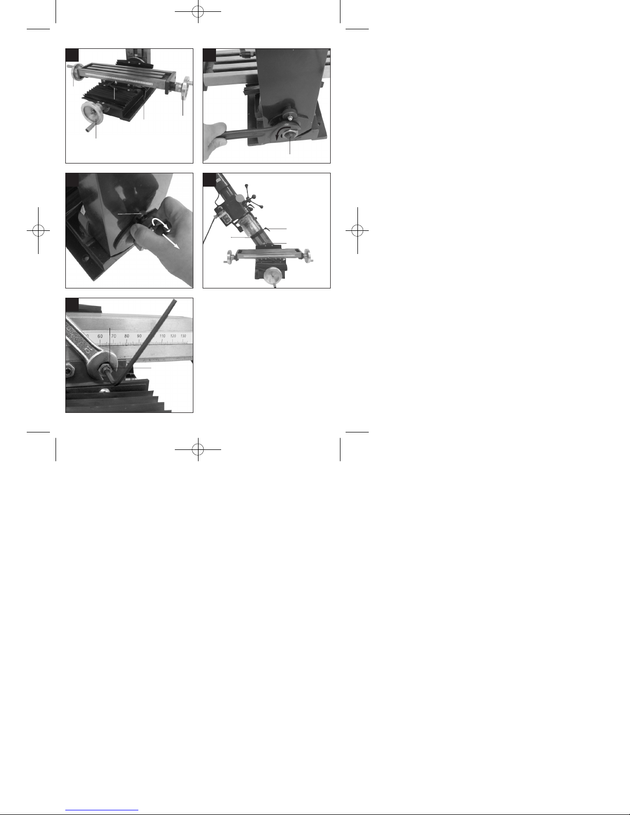
6.3.1 Maschine Einschalten (Abb. 3)
Vor dem Einschalten der Maschine muss der
klappbare Späneschutz (16) heruntergeklappt sein.
Zum Einschalten muss die grüne Taste (I) gedrückt
werden.
Leuchtet die grüne Kontrollleuchte (a) kann die
Maschine mittels des Drehzahl-Wahlschalters (6)
eingeschaltet und die gewünschte Drehzahl
eingestellt werden.
Leuchtet zusätzlich die orange Kontrollleuchte (b),
muss der Drehzahl-Wahlschalter (6) erst in „0“
Position gestellt werden und die gelbe Leuchte
erlischt wieder. Danach kann die gewünschte
Drehzahl an der Maschine eingestellt werden und die
Maschine läuft an.
6.3.2 Maschine Ausschalten
Maschine durch Drücken der roten „O“ Taste oder
durch drücken der „NOT AUS TASTE“ (c)
ausschalten und durch das ziehen des Netzsteckers
vom Netz trennen.
7. Bedienung und Einstellung
Achtung: Alle Einstellungen an der Maschine dürfen
nur bei gezogenem Netzstecker vorgenommen
werden.
7.1 Drehzahleinstellung (Bild 3-4)
Mittels des Getriebehebels (5) auf der Maschinenseite können zwei Drehzahlbereiche gewählt
werden.
Vordere Stellung (L) für den Drehzahlbereich
50 bis 1100 min
-1
Hintere Stellung (H) für den Drehzahlbereich
120 bis 2500 min
-1
Achtung: Drehzahlbereiche (L und H) nicht bei
laufender Spindel ändern! Die Drehzahl kann
innerhalb des Drehzahlbereiches stufenlos
eingestellt werden.
Die Feineinstellung der Drehzahl erfolgt über den
Drehzahlwahlschalter (6).
7.2 Richtigen Drehzahl / Schnittgeschwindigkeit
Die Wahl der richtigen Schnittgeschwindigkeit hat
große Auswirkungen auf die Standzeit des Werkzeuges und auf das Arbeitsergebnis. Sie ist je nach
Werkstoff unterschiedlich zu wählen. Die richtige
Schnittgeschwindigkeit erhalten Sie durch die
richtige Wahl der Drehzahl.
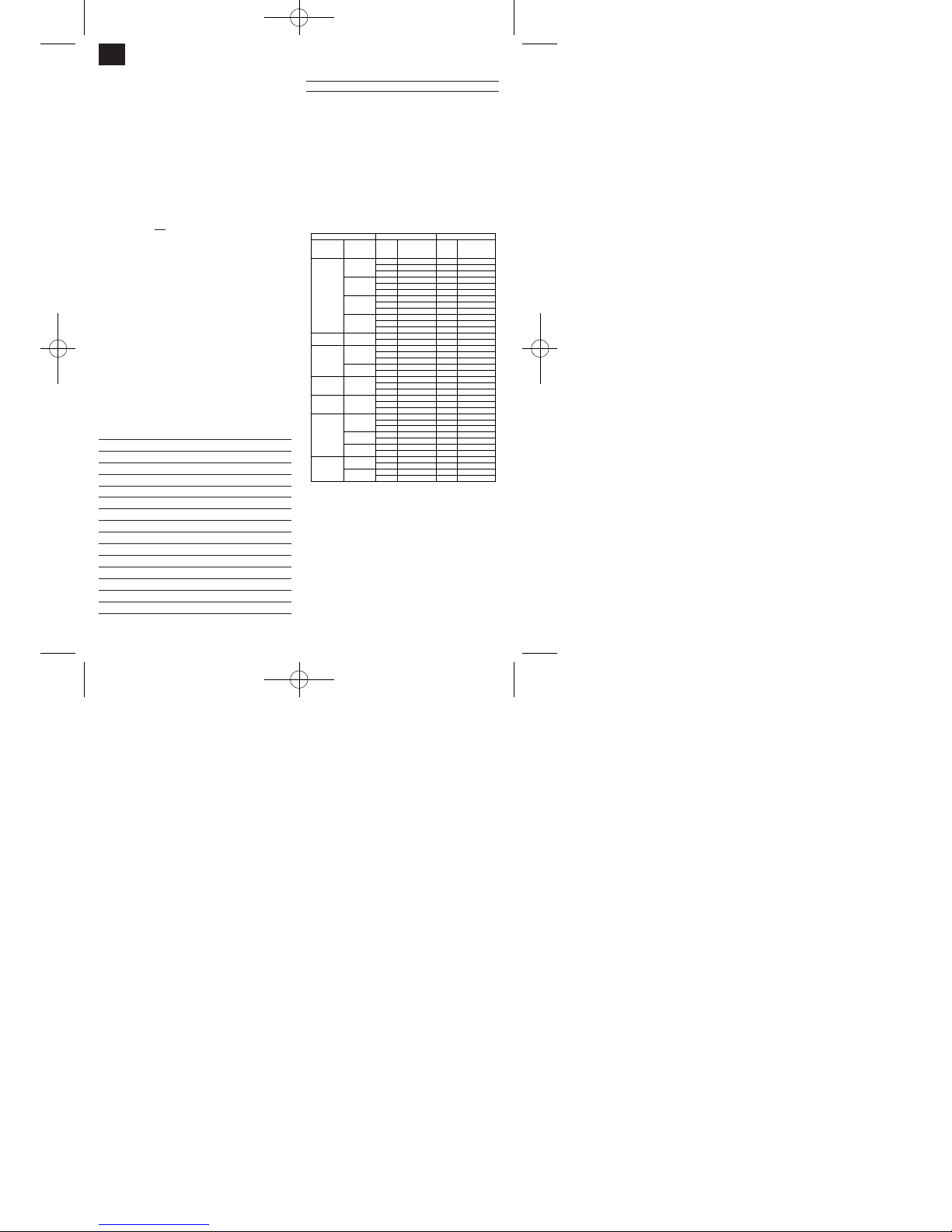
7.2.1 Bohren
Faustregel: Je kleiner die Löcher und je weicher der
Werkstoff, desto höher die Drehzahl.
Unten aufgeführte Liste hilft ihnen bei der Wahl der
Richtigen Drehzahl für die verschiedenen
Materialien.
Bei den angegebenen Drehzahlen handelt es sich
lediglich um Richtwerte.
Drehzahleinstellung siehe Kap.7.1
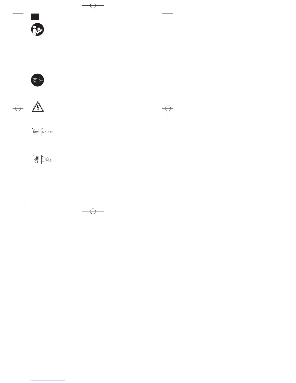
Ø Bohrer Grauguss Stahl Eisen Aluminium Bronze
3 2550 1600 2230 9500 8000
4 1900 1200 1680 7200 6000
5 1530 955 1340 5700 4800
6 1270 800 1100 4800 4000
7 1090 680 960 4100 3400
8 960 600 840 3600 3000
9 850 530 740 3200 2650
10 765 480 670 2860 2400
11 700 435 610 2600 2170
12 640 400 560 2400 2000
13 590 370 515 2200 1840
14 545 340 480 2000 1700
16 480 300 420 1800 1500
18 425 265 370 1600 1300
20 380 240 335 1400 1200
22 350 220 305 1300 1100
25 305 190 270 1150 950
7.2.2 Fräsen
Die Drehzahl lässt sich folgendermaßen berechnen:
n = v / ( x d )
n = Drehzahl in min
-1
v = Schnittgeschwindigkeit in m/min
d = Werkzeugdurchmesser in m
= 3,14
Die Werte für die Schnittgeschwindigkeiten und
maximalen Schnitttiefen für den jeweiligen Werkstoff
entnehmen Sie unten aufgeführter Liste oder einem
Tabellenbuch.
Anleitung_BT_MR_550_SPK7:_ 18.12.2007 15:44 Uhr Seite 9
Page 10
10
D
7.3 Spannen der Werkzeuge (Bild 3, 4, 6-8)
In der Arbeitsspindel dürfen ausschließlich
Werkzeuge, Spannvorrichtungen oder
Werkzeugaufnahmen mit Morsekegel MK3 und
Innengewinde M12 zu formschlüssigen Befestigung
verwendet werden. Reduzierhülsen dürfen nicht
verwendet werden!
7.3.1 Werkzeuge in Arbeitsspindel spannen
Maschine ausschalten und Netzstecker ziehen!
Spindelabdeckung (15) entfernen.
Kegelschaft (18) und Spindel (4) säubern und
entfetten.
Jetzt den Kegelschaft (18) in die Hülse der
Arbeitsspindel (4) stecken. Achtung: Um Verletzungen zu vermeiden sollte der Fräser mit
einem Lappen angefasst werden!
Zum Fixieren der Arbeitsspindel den Fixierstift
(17) seitlich in die Spindelhülse einstecken.
Zugstange (19) zum Befestigen des Kegel-
schaftes mit einem Maulschlüssel (SW10) festziehen. Die Zugstange muss mit ca. 8 Umdrehungen (im Uhrzeigersinn) in den Kegeldorn geschraubt werden. Wichtig: Sichern Sie das Werkzeug oder das Bohrfutter immer mit der Zugstange, um ein selbstständiges Lösen des
Werkzeuges auszuschließen.
Fixierstift (17) wieder entfernen.
Spindelabdeckung (15) wieder aufstecken.
7.3.2 Werkzeug aus Arbeitsspindel entfernen:
Maschine ausschalten und Netzstecker ziehen!
Spindelabdeckung (15) entfernen.
Zum Fixieren der Arbeitsspindel den Fixierstift
(17) seitlich in die Spindelhülse einstecken.
Zugstange mit Maulschlüssel (SW 10) entgegen
dem Uhrzeigersinn lösen.
Kegelschaft (18) vorsichtig durch Klopfen auf die
Zugstange (19) mit einem Gummihammer lösen
und aus der Spindelhülse nehmen. Um
Verletzungen zu vermeiden sollte der Fräser mit
einem Lappen angefasst werden!
Spindelabdeckung (15) wieder aufsetzen.
7.3.3 Handhabung des Bohrfutters
Im Bohrfutter (9) dürfen nur zylindrische Werk-
zeuge mit dem angegebenen maximalen Schaftdurchmesser gespannt werden. Nur
einwandfreies und scharfes Werkzeug benutzen.
Keine Werkzeuge benutzen, die an Schaft
beschädigt sind oder sonst in irgendeiner Weise
verformt oder beschädigt sind. Setzen Sie nur
Zubehör oder Zusatzgeräte, die vom Hersteller
freigegeben sind, ein.
Schaft des Werkzeuges ganz in das Bohrfutter
(9) einstecken und mit dem mitgelieferten Futterschlüssel festziehen.
Futterschlüssel wieder abziehen. Achten Sie auf
festen Sitz der eingespannten Werkzeuge.
Achtung: Futterschlüssel nicht stecken lassen.
Verletzungsgefahr durch Wegschleudern des
Futterschlüssels.
7.4 Spannen der Werkstücke
Achtung: Die Werkstücke müssen immer fest
eingespannt werden! Dies ist wichtig für die
Betriebssicherheit und für das Arbeitsergebnis.
Ist das Werkstück nicht fest eingespannt, kann es
durch die Vorschubkraft des Fräsers herausgerissen
und weggeschleudert werden.
Am besten eignet sich hierzu ein Maschinen-
schraubstock.(nicht im Lieferumfang enthalten
. Mit
Hilfe von Spannschrauben und Nutsteinen kann der
Maschinenschraubstock fest am Kreuztisch der
Maschine befestigt werden. Vor dem endgültigen
festziehen der Schrauben muss der
Maschinenschraubstock mittels einer Messuhr genau
parallel zu den Schlittenführungen ausgerichtet
werden.
Es können auch geeignete Spannpratzen (nicht im
Lieferumfang enthalten), zum befestigen des
Werkstückes am Maschinentisch verwendet werden.
Dabei ist auf die richtige Spannpratzengröße zu
achten., um eine festen Halt des Werkstückes zu
Werkstoff
Zugfestigkeit
Schnitt-
tiefe a
[mm]
Schnitt-
geschwindigkeit
v [m/min]
Schnitt-
tiefe a
[mm]
Schnitt-
geschwindigkeit
v [m/min]
0,5 70 - 50 1 200 - 150
3 50 - 30 6 100 - 70
10 30 - 20 10 70 - 50
0,5 45 - 30 1 150 - 110
3 30 - 20 6 80 - 55
10 18 - 12 10 55 - 35
0,5 30 - 20 1 110 - 75
3 20 - 15 6 55 - 35
10 18 - 10 10 35 - 25
- - 1 75 - 50
- - 3 50 - 30
- - 6 30 - 20
0,5 90 - 40 1 160 - 80
3 75 - 30 3 120 - 60
0,5 45 - 35 1 100 - 80
3 35 - 25 3 90 - 60
10 20 - 15 10 60 - 40
0,5 40 - 30 1 100 - 70
3 30 - 20 3 70 - 50
0,5 70 - 45 1 240 - 190
3 60 - 40 3 190 - 140
6 40 - 20 6 140 - 80
0,5 60 - 40 1 150 - 100
3 50 - 35 3 100 - 60
6 35 - 20 6 70 - 45
0,5 180 - 160 0,5 700 +
3 160 - 140 3 600 - 400
6 140 - 120 6 500 - 250
1 140 - 100 1 400 - 200
6 120 - 80 6 300 - 150
- - 1 200 - 120
- - 6 150 - 50
3 150 - 100 3 450 - 350
6 120 - 70 6 350 - 250
3 100 - 55 3 400 - 300
6 55 - 35 6 30 - 200
HartmetallSchnellarbeitsstahl
Kupfer
Legierungen
200 - 400
400 - 800
Aluminium
Legierungen
60 - 320
320 - 440
440 +
Schwarzer
Temperguss
350
Weißer
Temperguss
350 - 400
Automaten-
stahl
700
Gusseisen
mit Lamellen-
graphit
200
200 - 400
All. Baustahl,
Werkzeug-
stahl, Einsatz
und
Vergütungs-
stahl,
Stahlguss
500 - 700
700 - 900
900 - 1100
1100 - 1400
Anleitung_BT_MR_550_SPK7:_ 18.12.2007 15:44 Uhr Seite 10
Page 11

11
D
gewährleisten.
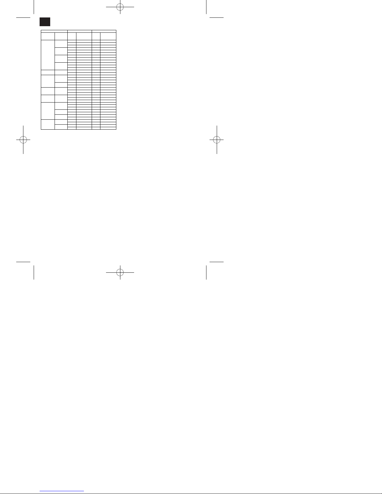
7.5 Vorschub (Abb.7,8)
Alle Vorschubbewegungen müssen von Hand
ausgeführt werden.
7.5.1 Normalvorschub des Fräskopfes
(Abb. 1/2/9)
Das Drehkreuz (14) des Vorschubes ganz von
der Maschine weg nach außen ziehen.
Das Werkzeug kann nun mittels des
Drehkreuzes schnell an das Werkstück
herangeführt werden.
Der Normalvorschub wird zum Ausführen von
Bohrungen verwendet.
Durch den Tiefenanschlag (12) kann die Bohr-
bzw. Frästiefe in z-Richtung begrenzt werden.
Dazu Feststellgriff (20) am Tiefenanschlag (12)
lösen
Tiefenanschlag auf die gewünschte Position ein-
stellen und Feststellgriff (20) wieder festziehen.
Die Vorschubposition kann an der Skala (21) ab-
gelesen werden.
7.5.2 Feinvorschub des Fräskopfes (Abb. 1/9)
Das Drehkreuz (14) so in Richtung Fräskopf (1)
schieben, dass die Zähne der Klauenkupplung
(27) ineinander greifen.
Der Fräser kann nun mittels des Stellrades für
den Feinvorschub (7) genau positioniert werden.
Ein Teilstriches des Skalenrings entspricht 0,02
mm Verfahrweg des Tisches.
Ist die gewünschte Frästiefe eingestellt muss der
Fräskopf (1) mittels des jeweiligen Klemmhebels
(28) fixiert werden.
7.5.3 Vorschub des Kreuztisches (Abb. 8)
Der Kreuztisch (2) der Maschine ist in zwei senk-
recht zueinander stehenden Achsen (X;Y)
manuell verfahrbar.
Der Vorschub beim Fräsen wird durch
Betätigung der Kurbeln (10;11) ausgeführt.
Durch den Skalenring an den Handkurbeln kann
man die Nullposition des Verfahrweges
einstellen.
Ein Teilstriches des Skalenrings entspricht 0,02
mm Verfahrweg des Tisches.
Wird eine Verfahrachse (X oder Y) des Tisches
nicht verwendet, empfiehlt es sich diese mittels
des jeweiligen Klemmhebels (22)
festzuklemmen.
7.6 Schwenken des Fräskopfes (Abb. 1,2, 11-13)
Zum Fräsen von Fasen oder V-Nuten kann der
Fräskopf nach links und rechts um jeweils 45°
geschwenkt werden.
Achtung: Stellen Sie vor Beginn der Einstellung
sicher, dass die Maschine fest auf der Arbeitsfläche
verschraubt ist!
Maschine ausschalten.
Maschinenkopf (1) mit einer Hand gut festhalten
um ein Wegkippen zu verhindern.
Befestigungsmutter (13) mit einem
Maulschlüssel (SW 36) lösen.
0° Arretierung (23) durch herausziehen
entriegeln.
Den gewünschten Keilwinkel an der Winkelskala
(24) einstellen.
Befestigungsmutter (13) wieder festziehen.
7.7 Gehrungsführungen justieren (Abb. 14)
Bei häufiger Benutzung kann sich der Abstand
zwischen den Gleitflächen des Längs- und
Querschlittens sowie des Fräskopfes ändern. Um die
einwandfreie Funktion und Bewegung zu
gewährleisten sollte die Gehrungsführungen etwa 1
mal pro Jahr nachjustiert werden.
Kontermuttern (25) lösen
Justierschrauben (26) so nachstellen, dass der
ausgeübte Druck auf die Gehrungsführung an
jeder Justierschraube gleichmäßig ist.
Justierschraube (26) mittels eines
Inbusschlüssels (3mm) in Position halten und
Kontermuttern (25) wieder festziehen.
Tip: Die Justierschrauben von außen beginnend
immer von zwei Seiten gleichmäßig anziehen,
um eine einheitliche Einstellung zu erhalten.
8. Bearbeitung
8.1 Bohren und Tiefenfräsen
Bohrfutter und Werkzeug wie in Kap. 7.2 be-
schrieben einsetzen und mit der Zugstange
sichern.
Bohrfutter mit Hilfe des Futterschlüssels fest-
ziehen.
Richtigen Drehzahl einstellen (siehe Kap. 7.1 -
7.2)
Spannen Sie das Werkstück gut mittels eines
Maschinenschraubstockes oder mittels
Spannpratzen gut fest.
Kreuztisch (2) in die (X- und Y-Richtung) in die
gewünschte Position bringen
Tiefenanschlag einstellen (siehe Kap. 7.5.1) und
darauf achten dass das Werkzeug nicht das
Anleitung_BT_MR_550_SPK7:_ 18.12.2007 15:44 Uhr Seite 11
Page 12

Werkstück berührt.
Nicht mehr gebrauchte Gegenstände aus dem
Arbeitsbereich entfernen.
Maschine einschalten und mit dem
Drehzahlwahlschalter (6) die richtige
Spindeldrehzahl einstellen.
Durchführen der Bohr- bzw. Fräsarbeit. Hinweis:
Bei großen Bohrungen sollte zuerst mit einem
kleinen Bohrer vorgebohrt werden. Ziehen Sie
den Bohrer während des Bohrens einige Male
aus dem Werkstück zurück, damit das Bohrloch
frei von Spänen bleibt.
Die Bohr- bzw. Frästiefe ergibt sich aus der Ein-
stellung des Tiefenanschlages (12)
Nach Beendigung der Arbeit Fräskopf wieder in
obere Position bringen und Maschine ausschalten.
Maschine und Spannvorrichtung reinigen und
ggf. einölen.
8.1.1 Senken und Zentrierbohren
Bitte beachten Sie dass Senken mit niedriger
Schnittgeschwindigkeit und niedrigem Vorschub,
während Zentrierbohren mit hoher
Schnittgeschwindigkeit und niedrigem Vorschub
durchzuführen ist.
8.2 Stirnfräsen
Spannfutter und Werkzeug einspannen (siehe
Kap. 7.1) und mit der Zugstange (19) sichern.
Spannfutter mit Hilfe des Futterschlüssels fest-
ziehen.
Richtigen Drehzahlbereich einstellen (siehe
Kap. 7.1-7.2)
Achtung: Drehzahlbereiche (L und H) nicht bei
laufender Spindel ändern!
Spannen Sie das Werkstück gut mittels eine Ma-
schinenschraubstockes oder mittels
Spannpratzen gut fest.
Arbeitstisch in die (X- und Y-Richtung) in die ge-
wünschte Position bringen
Tiefenanschlag einstellen (siehe 7.4.1) und dar-
auf achten dass das Werkzeug nicht das
Werkstück berührt.
Nicht mehr gebrauchte Gegenstände aus dem
Arbeitsbereich entfernen.
Maschine einschalten und mit dem
Drehzahlwahlschalter(6) die gewünschte
Spindeldrehzahl einstellen.
Fräsarbeit durchführen. Dazu Kreuztisch mittels
der Handkurbeln in X- und Y-Richtung verstellen.
(siehe 7.5.3)
Nach Beendigung der Arbeit Maschine ausschal-
ten und Fräskopf (1) wieder in obere Position
bringen.
Maschine und Spannvorrichtung reinigen und
ggf. einölen.
Nach dem Gebrauch der Maschine muss der
Arbeitstisch wieder gereinigt und eingeölt
werden.
9. Pflege und Wartung
Vor allen Pflege und Wartungsarbeiten ist der
Netzstecker zu ziehen! Die Maschine ist in
regelmäßigen Abständen (je nach
Benutzungshäufigkeit) zu warten. Die
Wartungsarbeiten sollten genau dokumentiert
werden.
Kegelschäfte und Fräser sauber halten.
Zum Schutz, gleiche Fräser bei Nichtgebrauch
am besten in einer Box aufbewahren.
Überprüfen Sie den gesamten Stromkreis (
Schalter, Stecker, Kontakte etc.) auf
ordnungsgemäße Funktion.
Um größeren Schäden und Verletzungen vorzu-
beugen, wenden Sie sich bei Störungen, welche
über die normale Wartung hinausgehen, bitte an
unsere Kundendienst. Die Serviceadresse finden
Sie nachfolgend in der Garantieurkunde.
Überprüfen Sie den Fräsmaschinenkopf auf
leichte Beweglichkeit und achten Sie darauf dass
er sich nicht gelockert hat.
Prüfen Sie die Spindel auf Überschwingen.
Alle Schraubverbindungen auf festen Sitz über-
prüfen.
9.1 Schmierung
Um stets gute Arbeitsergebnisse zu gewährleisten
und die Maschine vor Korrosion zu schützen, muss
die Maschine in regelmäßigen Abständen
abgeschmiert und gefettet werden. Verteilen Sie das
Schmieröl bzw. Schmierfett gleichmäßig mit einem
Pinsel oder einem nicht fusselnden Lappen.
Schmierstellen und Schmierstoffe:
Alle blanken Maschinenteile: Schmieröl
Zahnstange an Säule: Schmieröl
Maschinentisch: Schmieröl
Mechanismus des Feinvorschubes: Schmieröl
Vorschubspindel Längsschlitten: Schmieröl
Vorschubspindel Querschlitten: Schmieröl
Prismenführung Fräskopf: Schmierfett
Drehlager Fräskopf: Schmierfett
Prismenführung Querschlitten: Schmierfett
Prismenführung Längsschlitten: Schmierfett
12
D
Anleitung_BT_MR_550_SPK7:_ 18.12.2007 15:44 Uhr Seite 12
Page 13

10. Austausch der
Netzanschlussleitung
Wenn die Netzanschlussleitung dieses Gerätes
beschädigt wird, muss sie durch den Hersteller oder
seinen Kundendienst oder eine ähnlich qualifizierte
Person ersetzt werden, um Gefährdungen zu
vermeiden.
11. Reinigung, Wartung und
Ersatzteilbestellung
Ziehen Sie vor allen Reinigungsarbeiten den
Netzstecker.
11.1 Reinigung
Halten Sie Schutzvorrichtungen, Luftschlitze und
Motorengehäuse so staub- und schmutzfrei wie
möglich. Reiben Sie das Gerät mit einem
sauberen Tuch ab oder blasen Sie es mit
Druckluft bei niedrigem Druck aus.
Wir empfehlen, dass Sie das Gerät direkt nach
jeder Benutzung reinigen.
Reinigen Sie das Gerät regelmäßig mit einem
feuchten Tuch und etwas Schmierseife.
Verwenden Sie keine Reinigungs- oder
Lösungsmittel; diese könnten die Kunststoffteile
des Gerätes angreifen. Achten Sie darauf, dass
kein Wasser in das Geräteinnere gelangen kann.
11.2 Wartung
Im Geräteinneren befinden sich keine weiteren zu
wartenden Teile.
11.3 Ersatzteilbestellung:
Bei der Ersatzteilbestellung sollten folgende
Angaben gemacht werden;
Typ des Gerätes
Artikelnummer des Gerätes
Ident-Nummer des Gerätes
Ersatzteilnummer des erforderlichen Ersatzteils
Aktuelle Preise und Infos finden Sie unter
www.isc-gmbh.info
12. Entsorgung und Wiederverwertung
Das Gerät befindet sich in einer Verpackung um
Transportschäden zu verhindern. Diese Verpackung
ist Rohstoff und ist somit wieder verwendbar oder
kann dem Rohstoffkreislauf zurückgeführt werden.
Das Gerät und dessen Zubehör bestehen aus
verschiedenen Materialien, wie z.B. Metall und
Kunststoffe. Führen Sie defekte Bauteile der
Sondermüllentsorgung zu. Fragen Sie im
Fachgeschäft oder in der Gemeindeverwaltung nach!
13
D
Anleitung_BT_MR_550_SPK7:_ 18.12.2007 15:44 Uhr Seite 13
Page 14
14
GB
“Caution - Read the operating instructions to reduce the risk of inquiry”
Wear safety goggles.
Sparks generated during working or splinters, chips and dust emitted by the device can cause
loss of sight.
Remove the power plug!
Important! Work on electrical equipment may only be carried out by a qualified electrician!
Important! Wait until the equipment has stopped before actuating the selector lever for
the speed range!
Important! The hinged jaw chuck guard must be in the swung-out position before the
machine is switched on!
Anleitung_BT_MR_550_SPK7:_ 18.12.2007 15:44 Uhr Seite 14
Page 15

Important!
When using the equipment, a few safety precautions
must be observed to avoid injuries and damage.
Please read the complete operating instructions and
safety regulations with due care. Keep this manual in
a safe place, so that the information is available at all
times. If you give the equipment to any other person,
hand over these operating instructions and safety
regulations as well. We cannot accept any liability for
damage or accidents which arise due to a failure to
follow these instructions and the safety instructions.
1. Layout (Figs. 1-4)
1. Routing head
2. Compound table
3. Machine column
4. Work spindle
5. Gear lever
6. Speed selector switch
7. Wheel selector for fine feed
8. ON/OFF switch
9. Ring gear drill chuck
10. Hand crank for cross slide
11. Hand crank for saddle slide
12. Depth stop
13. Fixing nut for angle adjustment
14. Star handle
15. Spindle guard
16. Hinged chip guard
2. Items supplied
앬 Drilling and routing machine
앬 Drill chuck key
앬 Hook spanner
앬 Locating pin
앬 Tools
3. Proper use
This machine is designed for the drilling, deep
routing and face routing of small workpieces (max.
dimensions: 300 mm x 200 mm x 200 mm) made
from metal, plastic or similar materials. Only drilling
and routing tools with a cylindrical shaft of max. 16
mm may be used with the standard ring gear drill
chuck. The tool diameter for the machining of metal
(ST37) must be no more than 13 mm. Tools with a
tapered shank (MK3) can also be mounted directly in
the work spindle. This drilling and routing machine is
suitable only for household use and must not be
used for industrial applications. The machine is to be
used only for its prescribed purpose. Any other use is
deemed to be a case of misuse.
The user/operator and not the manufacturer will be
held liable for damage and/or injuries of any kind that
result from such misuse. To use the machine
properly you must also observe the safety
regulations, the assembly instructions and the
operating instructions to be found in this manual. All
persons who use and service the machine have to
be acquainted with this manual and must be
informed about the machineʼs potential hazards. It is
also imperative to observe the accident prevention
regulations in force in your area. The same applies
for the general rules of health and safety at work.
Please note that our equipment has not been
designed for use in commercial, trade or industrial
applications. Our warranty will be voided if the
machine is used in commercial, trade or industrial
businesses or for equivalent purposes.
The manufacturer will not be liable for any changes
made to the machine nor for any damage resulting
from such changes. Even when the machine is used
as prescribed it is still impossible to eliminate certain
residual risk factors. The following hazards may arise
in connection with the machinesʼ construction and
design:
앬 Contact with the jaw chuck where it is not
covered.
앬 Reaching into rotating parts (risk of injury).
앬 Catapulting of workpieces and parts of workpieces
from the machine.
앬 Harmful coolants and lubricants. Make sure they
are disposed of in an environmentally friendly
manner.
앬 Contact with rotating components where they are
not covered. Risk of injury!
앬 Caution! Risk of injury! Always withdraw jaw chuck
keys immediately and never leave them inserted
in the chuck!
앬 Risk of injury from the routing tool even when it is
not in use.
앬 Eye injuries can be caused by flying chips and
other splinters. You MUST wear safety goggles!
15
GB
Anleitung_BT_MR_550_SPK7:_ 18.12.2007 15:44 Uhr Seite 15
Page 16

4. Important information
Please read the directions for use carefully and
observe the safety information before using the
machine for the first time. It is important to
consult these instructions in order to acquaint
yourself with the machine, its proper use and
safety precautions. Always keep the instructions
so that the user can access them at any time.
앬 It is absolutely essential that personal protective
equipment is worn whenever working with the
machine.
앬 To prevent eye injuries, always wear safety
goggles.
앬 You must wear a hair net or suitable work cap if
you have long hair.
앬 Wear close-fitting work clothes.
앬 The tool could catch sleeves etc. as it rotates.
앬 Use a suitable chip hook to remove chips. Never
remove chips using just your hand.
앬 With the machine switched off, chips are best
removed using a brush or the like.
앬 Only people over the age of 18 who are familiar
with how the machine works may operate the
machine.
앬 Young people aged between 16 and 18 may only
work with the machine under the supervision of an
adult.
앬 Check that the safeguard is functioning properly
before starting work.
앬 Do not overload the machine. Electric tools work
better and safer when used within their quoted
capacity range.
앬 Use the correct tool and make sure that the tools
(routing tool, drill) are not blunt or broken.
앬 Always lead the power cable from the rear of the
machine. Protect the cable from heat, oil and
sharp edges.
앬 Pull out the power plug before carrying out repairs
and maintenance and when the machine is not in
use.
앬 Work on electrical equipment may only be carried
out by a qualified electrician. Only original parts
may be used.
앬 Clean workplaces make work easier. Concentrate
on what you are doing. Use common sense when
working.
앬 Make sure that the base on which the machine is
placed can support the weight of the machine and
is sufficiently stable for no vibrations to occur
during machining.
앬 All bare parts of the machine are already well
greased in order to protect them from corrosion.
Clean the machine with a suitable environmentally
friendly cleaning agent before using it for the first
time.
앬 Important! Close the safety guard for the jaw
chuck before switching the machine on.
앬 This machine must not be used for the machining
of any materials that are toxic or generate dust
such as wood, Teflon etc.
앬 Do not use the machine near flammable liquids or
gases.
앬 Use the machine only in suitable rooms and do
not expose the machine to moist or wet
environments.
앬 Provide good lighting while you work.
앬 Do not use the cable to pull the plug out of the
socket.
앬 Make sure that the workpiece is clamped in firmly
when working. Always clamp the workpiece in a
machine vice or by means of clamping claws.
앬 Use only tools that are sharp and clean.
앬 Switch the machine off immediately in dangerous
situations or if technical faults occur and pull out
the power plug!
앬 If the machine is damaged, you must stop working
with it and pull out the power plug.
앬 Important! Only replacement tools and accesso
ries which have been approved by the
manufacturer may be used. The use of nonapproved parts can put you at risk of injury.
앬 Keep your work area clean and tidy. Untidy work
areas can cause accidents.
앬 Wear safety goggles. You must also wear a face
or dust mask when carrying out work that
produces a lot of dust.
앬 Remove jaw keys and other tools before starting
work.
5. Technical data
Rated voltage 230 V ~ / 50 Hz
Power rating 550 W S3 50% 400W S1
Rotational speed range (L) low 50-1100 min
-1
Rotational speed range (H) high 120-2500 min
-1
Morse taper in spindle MK 3
Max. drill bit diameter 16 mm
End-routing cutter diameter 13 mm
Face-routing cutter diameter 30 mm
Compound table 410 x 112 mm
Max. table adjustment in x 250 mm
Max. table adjustment in y 100 mm
Max. spindle stroke 220 mm
Angle adjustment l/r -45° - +45°
LPA sound pressure level 83 dB(A)
Protection type IP 23
Weight 62 kg
16
GB
Anleitung_BT_MR_550_SPK7:_ 18.12.2007 15:44 Uhr Seite 16
Page 17

Operating mode S3 (periodic intermittent
operation):
The machine may be operated at the power rating for
a certain period (relative ON period as % of cycle
time). Afterwards the machine must be stopped for a
while (rest period) to prevent it from overheating. The
cycle time is made up of the load period and the rest
period. The machine will not cool down to room
temperature while not running between the cycle
times. Unless stated otherwise, the cycle time is 10
minutes.
6. Starting up
Important!
앬 Pull out the power plug before carrying out any
assembly and adjustment work.
앬 To avoid damage in transit, always transport the
machine upright and preferably in the original
packaging.
앬 Make allowance for the weight of the machine!
The net weight of the machine is 62 kg. Use
suitable means of transport that can support the
weight of the machine. Should no means of transport be available, lift the machine carefully so as
to avoid injury to people and damage to the
machine itself.
앬 Protect the machine against moisture and rain.
앬 The machine may only be installed and used in
dry, well-ventilated rooms. The temperature range
for operating the machine should be between +15°
and +40°.
앬 Are the tool chuck and routing cutter sufficiently
secure?
앬 Check to see if any parts of the machine have
worked loose.
앬 Has the right rotational speed range been
chosen?
앬 Are the machine and clamping devices clean and
free of chips?
앬 Check to make sure that the fixing screws of the
concentric chuck have been tightened and that the
work spindle can be easily rotated by hand.
앬 All covers and safety devices must be properly
fitted before the machine is switched on.
앬 The jaw chuck must be able to run freely.
앬 Before switching on, make sure that everything
has been properly assembled and that moving
parts can move easily.
앬 Before you connect the machine to the power
supply, make sure the data on the rating plate is
the same as that for your mains.
앬 Fit the supplied crank handles (Figure 5).
6.2 Installation
Set the machine up on a level base (workbench etc.).
Important: The machine must be screwed tight to
the base using four screws. To do this, use the four
fixing holes in the baseplate of the machine.
Make sure that there is enough space for the
compound table to traverse and for angle
adjustments.
You must also make sure that what is underneath
the machine is sufficiently stable to support the
weight (approx. 62 kg) of the machine!
All bare parts of the machine are already greased in
order to protect them from corrosion. Clean the
machine with a suitable environmentally friendly
cleaning agent before using it for the first time. Do
not use any cleaning agents that could attack the
paintwork of the machine and ensure sufficient
ventilation during cleaning. Lubricate the machine
with non-acidic lubricating oil again after cleaning.
Important: Oil, grease and cleaning agents are
harmful to the environment and must be disposed of
in an environmentally compatible way - not with
household rubbish!
6.3 Mains connection / switch
The machine may only be operated with singlephase current 230 Volt / 50 Hz. The electric circuit of
the house must be protected by no more than a 16A
fuse.
6.3.1 Switching on the machine (Fig. 3)
The hinged chip guard (16) must be in the “down”
position before the machine is switched on.
To switch on, press the green button (I).
If the green indicator light (a) illuminates, the
machine can be switched on using the speed
selector switch (6) and the desired rotational speed
can be set.
If the orange indicator light (b) also illuminates, the
speed selector switch (6) must be put into the “0”
position and the yellow light will go off again. The
desired rotational speed of the machine can then be
set and the machine will start up.
6.3.2 Switching off the machine
Switch the machine off by pressing the red “O”
button or the “EMERGENCY OFF” button (c) and
then unplug the power plug.
17
GB
Anleitung_BT_MR_550_SPK7:_ 18.12.2007 15:44 Uhr Seite 17
Page 18
7. Operation and adjustment
Important: Always unplug the power plug before
making any adjustments to the machine.
7.1 Setting the rotational speed (Figs. 3-4)
Use the gear lever (5) on the machine side to choose
between two speed ranges.
Front position (L) for the rotational speed rang
50 to 1100 min
-1
Rear position (H) for the rotational speed range
120 to 2500 min
-1
Important: Do not change rotational speed ranges
(L and H) while the spindle is running! The rotational
speed can be adjusted infinitely within the speed
range. Use the speed selector switch (6) to finely
adjust the rotational speed.
7.2 Correct rotational speed / cutting speed
The choice of the correct cutting speed has an
enormous effect on the service life of the tool and on
the work results. The right speed depends on the
material. If the chosen rotational speed is correct, the
cutting speed will also be correct.
7.2.1 Drilling
Rule of thumb: The smaller the hole and the softer
the material, the higher the speed of rotation.
The table below will help you select the proper speed
for the various materials.
Note: The rotational speeds shown are merely
suggested values.
To adjust the speed, see chapter 7.1.
Drill bit Ø Cast iron Steel Iron Aluminium Bronze
3 2550 1600 2230 9500 8000
4 1900 1200 1680 7200 6000
5 1530 955 1340 5700 4800
6 1270 800 1100 4800 4000
7 1090 680 960 4100 3400
8 960 600 840 3600 3000
9 850 530 740 3200 2650
10 765 480 670 2860 2400
11 700 435 610 2600 2170
12 640 400 560 2400 2000
13 590 370 515 2200 1840
14 545 340 480 2000 1700
16 480 300 420 1800 1500
18 425 265 370 1600 1300
20 380 240 335 1400 1200
22 350 220 305 1300 1100
25 305 190 270 1150 950
7.2.2 Routing
The rotational speed can be calculated as follows:
n = v / ( x d )
n = rotational speed in min
-1
v = cutting speed in m/min
d = tool diameter in m
= 3.14
The values for the cutting speeds and maximum
cutting depths for the relevant material are given in
the list below or in a book of tables.
7.3 Clamping the tools (Figs. 3,4,6-8)
Only tools, clamping fixtures or tool chucks with
Morse taper MK3 and internal thread M12 may be
used to ensure positive fixing in the work spindle.
Reducing bushes must not be used!
7.3.1 Clamping tools in the work spindle
앬 Switch the machine off and unplug the power
plug.
앬 Remove the spindle guard (15).
앬 Clean and degrease the tapered shank (18) and
spindle (4).
앬 Now insert the tapered shank (18) into the bush of
the work spindle (4). Important: To avoid injury,
18
GB
Material
Tensile
strength
cutting
depth
a [mm]
Cutting speed
v [m/min]
Cutting
depth
a [mm]
Cutting speed
v [m/min]
0,5 70 - 50 1 200 - 150
3 50 - 30 6 100 - 70
10 30 - 20 10 70 - 50
0,5 45 - 30 1 150 - 110
3 30 - 20 6 80 - 55
10 18 - 12 10 55 - 35
0,5 30 - 20 1 110 - 75
3 20 - 15 6 55 - 35
10 18 - 10 10 35 - 25
- - 1 75 - 50
- - 3 50 - 30
- - 6 30 - 20
0,5 90 - 40 1 160 - 80
3 75 - 30 3 120 - 60
0,5 45 - 35 1 100 - 80
3 35 - 25 3 90 - 60
10 20 - 15 10 60 - 40
0,5 40 - 30 1 100 - 70
3 30 - 20 3 70 - 50
0,5 70 - 45 1 240 - 190
3 60 - 40 3 190 - 140
6 40 - 20 6 140 - 80
0,5 60 - 40 1 150 - 100
3 50 - 35 3 100 - 60
6 35 - 20 6 70 - 45
0,5 180 - 160 0,5 700 +
3 160 - 140 3 600 - 400
6 140 - 120 6 500 - 250
1 140 - 100 1 400 - 200
6 120 - 80 6 300 - 150
- - 1 200 - 120
- - 6 150 - 50
3 150 - 100 3 450 - 350
6 120 - 70 6 350 - 250
3 100 - 55 3 400 - 300
6 55 - 35 6 30 - 200
Hard metalHigh-speed steel
Copper
alloys
200 - 400
400 - 800
Aluminium
alloys
60 - 320
320 - 440
440 +
Blackheart
iron
350
White
malleable
iron
350 - 400
Free-cutting
steel
700
Gray cast
iron
200
200 - 400
Gen.
Structural
steel; tool
steel; case-
hardened
and
tempered
steel; cast
steel
500 - 700
700 - 900
900 - 1100
1100 - 1400
Anleitung_BT_MR_550_SPK7:_ 18.12.2007 15:44 Uhr Seite 18
Page 19

always use a cloth to hold the routing cutter!
앬 To fix the work spindle in position, insert the
locating pin (17) into the side of the spindle bush.
앬 To fix the tapered shank in position, tighten the tie
rod (19) using an open-end wrench (SW10). The
tie rod must be screwed into the taper mandrel
with about 8 turns (clockwise) of the wrench.
Important: Always secure the tool or the drill
chuck with the tie rod in order to prevent the tool
from working loose.
앬 Remove the locating pin (17).
앬 Reattach the spindle guard (15).
7.3.2 Removing the tool from the work spindle:
앬 Switch the machine off and unplug the power
plug.
앬 Remove the spindle guard (15).
앬 To fix the work spindle in position, insert the
locating pin (17) into the side of the spindle bush.
앬 Loosen the tie rod by turning the open-end wrench
(SW10) anticlockwise.
앬 Loosen the tapered shank (18) carefully by gently
tapping the draw bar (19) with a rubber hammer
and remove it from the spindle bush. To avoid
injury, always use a cloth to hold the routing cutter!
앬 Reattach the spindle guard (15).
7.3.3 Handling the drill chuck
앬 Only cylindrical tools with the stipulated maximum
shaft diameter may be clamped in the drill chuck
(9). Only use a tool that is sharp and free of
defects. Do not use a tool whose shaft is
damaged or which is deformed or flawed in any
other way. Use only accessories or auxiliary units
that have been approved by the manufacturer.
앬 Insert the shaft of the tool all the way into the drill
chuck (9) and tighten it using the supplied chuck
key.
앬 Pull out the chuck key. Ensure that the clamped
tool is firmly seated.
Important: Do not leave the chuck key in. Doing
so will cause the chuck key to be catapulted out,
which could cause injury.
7.4 Clamping the workpieces
Important: Workpieces must always be clamped
tightly! This is important both for your own safety and
for the work results. If the workpiece is not clamped
tightly, it could be torn out by the feed force of the
routing cutter and catapult out.
The best thing to do is to use a machine vice (not
included in delivery). The machine vice can be
secured firmly to the compound table of the machine
using tightening screws and slide blocks. Before
tightening the screws for the last time, use a dial
gauge to make sure that the machine vice is aligned
exactly parallel to the saddle guides.
You can also use suitable clamping claws (not
included in delivery) to fix the workpiece to the
machine table. You must make sure that the
clamping claws are the right size to guarantee that
the workpiece is fixed securely.
7.5 Feed (Figs. 7,8)
All feed movements must be executed by hand.
7.5.1 Normal feed of the routing head (Figs. 1,2,9)
앬 Pull the star handle (14) of the feeder completely
away from the machine.
앬 The tool can now be brought rapidly towards the
workpiece using the star handle.
앬 Normal feed is used for drilling operations.
앬 The drilling or routing depth can be limited in the z
direction by means of the depth stop (12).
앬 To do so, loosen the locking handle (20) on the
depth stop (12).
앬 Set the depth stop to the required position and
tighten the locking handle (20) again.
앬 The position of the feed can be read on the scale
(21).
7.5.2 Fine feed of the routing head (Figs. 1,9)
앬 Push the star handle (14) towards the routing
head (1) so that the teeth of the jaw clutch (27)
intermesh.
앬 The routing cutter can now be positioned exactly
using the wheel selector for fine feed (7).
앬 One notch on the scale ring corresponds to 0.02
mm of travel of the table.
앬 Once the desired routing depth has been set, the
routing head (1) must be fixed in position using
the relevant clamping lever (28).
7.5.3 Feed of the compound table (Fig. 8)
앬 The compound table (2) of the machine can be
moved manually in two perpendicular directions
(X,Y).
앬 For routing jobs, the feed is executed by operating
the cranks (10,11).
앬 The zero position of the travel can be set using
the scale ring on the hand cranks.
앬 One notch on the scale ring corresponds to 0.02
mm of travel of the table.
앬 If one traversing axis (X or Y) of the table is not
used, it should be clamped tight by means of the
relevant clamping lever (22).
19
GB
Anleitung_BT_MR_550_SPK7:_ 18.12.2007 15:44 Uhr Seite 19
Page 20

7.6 Swiveling the routing head (Fig. 1,2,11-13)
The routing head can be swiveled 45° to the left or
right to enable chamfers or V-grooves to be cut.
Important: Before starting adjustment, make sure
that the machine is screwed tight to the working
surface!
앬 Switch the machine off.
앬 Hold the machine head (1) tightly with one hand to
prevent it from tipping over.
앬 Loosen the fixing nuts (13) using an open-end
wrench (SW 36).
앬 Unlock the 0° lock (23) by pulling it out.
앬 Set the desired wedge angle using the angle scale
(24).
앬 Tighten the fixing nuts (13) again.
7.7 Adjusting miter guides (Fig. 14)
If the machine is used frequently, the gap between
the sliding faces of the saddle slide and cross slide
and the routing head can change. To guarantee
perfect functioning and movement, readjust the miter
guides once every year or so.
앬 Undo the lock nuts (25).
앬 Adjust the adjustment screws (26) so that the
pressure exerted on the miter guide is the same at
every adjustment screw.
앬 Hold the adjustment screw (26) in position using
an Allen key (3 mm) and tighten the lock nuts (25)
again.
앬 Tip: To ensure uniform adjustment, always tighten
the adjustment screws evenly from two sides,
starting from the outside.
8. Machining
8.1 Drilling and deep routing
앬 Fit the drill chuck and tool as described in chapter
7.2 and lock them with the tie rod.
앬 Tighten the drill chuck using the chuck key.
앬 Set the correct rotational speed
(see chapter 7.1- 7.2).
앬 Clamp the workpiece firmly using a machine vice
or by means of clamping claws.
앬 Bring the compound table (2) into the desired
position (X or Y direction).
앬 Set the depth stop (see chapter 7.5.1), making
sure that the tool does not touch the workpiece.
앬 Remove from the working area any objects that
are no longer needed.
앬 Switch the machine on and set the correct spindle
speed using the speed selector switch (6).
앬 Carry out the drilling and routing work. Note:
Larger drill holes should be predrilled with a small
drill bit first. Withdraw the drill from the workpiece
several times while drilling so that the drill hole
remains free of chips.
앬 The drilling or routing depth depends on the
setting of the depth stop (12).
앬 After finishing the work, return the routing head to
the upper position and switch the machine off.
앬 Clean the machine and clamping fixture and
lubricate if necessary.
8.1.1 Countersinking and center-drilling
앬 Remember that countersinking should be carried
out with a low cutting speed and low feed, while
center-drilling should be carried out with a high
cutting speed and low feed.
8.2 Face routing
앬 Clamp the clamping chuck and tool in place (see
chapter 7.1) and lock them with the tie rod (19).
앬 Tighten the chuck using the chuck key.
앬 Set the correct rotational speed
(see chapter 7.1-7.2).
앬 Important: Do not change rotational speed
ranges (L and H) while the spindle is running!
앬 Clamp the workpiece firmly using a machine vice
or by means of clamping claws.
앬 Bring the table into the desired position (X or Y
direction).
앬 Set the depth stop (see chapter 7.4.1), making
sure that the tool does not touch the workpiece.
앬 Remove from the working area any objects that
are no longer needed.
앬 Switch the machine on and set the desired spindle
speed using the speed selector switch (6).
앬 Carry out the routing work. To do this, adjust the
compound table in the X and Y direction using the
hand cranks (see 7.5.3).
앬 After finishing the work, switch the machine off
and return the routing head (1) to the upper
position.
앬 Clean the machine and clamping fixture and
lubricate if necessary.
The work table must be cleaned and lubricated
again after the machine has been used.
9. Care and maintenance
Always pull out the power plug before carrying
out care and maintenance work! Machine
maintenance is required at regular intervals
(depending on how often it is used). The
maintenance work should be documented exactly.
앬 Keep the tapered shanks and routing cutter clean.
앬 For added protection, identical routing cutters are
20
GB
Anleitung_BT_MR_550_SPK7:_ 18.12.2007 15:44 Uhr Seite 20
Page 21

best kept in a box when not in use.
앬 Check that the whole electric circuit (switches,
plugs, contacts etc.) is functioning properly.
앬 To prevent further damage and injury, please
contact our Customer Services department if any
faults occur which require more than the normal
maintenance. The address is given in the warranty
card.
앬 Check that the routing head can move easily and
make sure that it has not worked loose.
앬 Check the spindle for excess vibration.
앬 Check that all the screw connections are tight.
9.1 Lubrication
If consistently good results are to be achieved and
the machine is to be protected against corrosion, it
must be lubricated and greased at regular intervals.
Spread the lubricating oil or grease evenly using a
brush or non-fluffy cloth.
Lubricating points and lubricants:
All bare parts of the machine: Lubricating oil
Tie rod on column: Lubricating oil
Machine table: Lubricating oil
Fine feed mechanism: Lubricating oil
Saddle slide feed spindle: Lubricating oil
Cross slide feed spindle: Lubricating oil
Routing head inverted V-track: Lubricating grease
Routing head pivot bearing: Lubricating grease
Cross slide inverted V-track: Lubricating grease
Saddle slide inverted V-track: Lubricating grease
10. Replacing the power cable
If the power cable for this equipment is damaged, it
must be replaced by the manufacturer or its aftersales service or similarly trained personnel to avoid
danger.
11. Cleaning, maintenance and
ordering of spare parts
Always pull out the mains power plug before starting
any cleaning work.
11.1 Cleaning
Keep all safety devices, air vents and the motor
housing free of dirt and dust as far as possible.
Wipe the equipment with a clean cloth or blow it
with compressed air at low pressure.
We recommend that you clean the device
immediately each time you have finished using it.
Clean the equipment regularly with a moist cloth
and some soft soap. Do not use cleaning agents
or solvents; these could attack the plastic parts
of the equipment. Ensure that no water can seep
into the device.
11.2 Maintenance
There are no parts inside the equipment which
require additional maintenance.
11.3 Ordering replacement parts
Please quote the following data when ordering
replacement parts:
Type of machine
Article number of the machine
Identification number of the machine
Replacement part number of the part required
For our latest prices and information please go to
www.isc-gmbh.info
12. Disposal and recycling
The unit is supplied in packaging to prevent its being
damaged in transit. This packaging is raw material
and can therefore be reused or can be returned to
the raw material system.
The unit and its accessories are made of various
types of material, such as metal and plastic.
Defective components must be disposed of as
special waste. Ask your dealer or your local council.
21
GB
Anleitung_BT_MR_550_SPK7:_ 18.12.2007 15:44 Uhr Seite 21
Page 22

22
F
Tirez la fiche de contact!
Attention! Les travaux sur des installations électriques doivent uniquement être effectués par
un(e) spécialiste électricien(ne)!
Attention! N’actionnez le levier de sélection de plage de vitesse qu’à l’arrêt!
Attention ! Avant la mise en service, la protection du mandrin doit se trouver en position
relevée!
« Avertissement – Lisez ce mode dʼemploi pour diminuer le risque de blessures »
Portez des lunettes de protection.
Les étincelles générées pendant travail ou les éclats, copeaux et la poussière sortant de
lʼappareil peuvent entraîner une perte de la vue.
Anleitung_BT_MR_550_SPK7:_ 18.12.2007 15:44 Uhr Seite 22
Page 23

Attention !
Lors de lʼutilisation dʼappareils, il faut respecter
certaines mesures de sécurité afin dʼéviter des
blessures et dommages. Veuillez donc lire
attentivement ce mode dʼemploi/ces consignes de
sécurité. Veillez à le conserver en bon état pour
pouvoir accéder aux informations à tout moment. Si
lʼappareil doit être remis à dʼautres personnes, veillez
à leur remettre aussi ce mode dʼemploi/ces
consignes de sécurité. Nous déclinons toute
responsabilité pour les accidents et dommages dus
au non-respect de ce mode dʼemploi et des
consignes de sécurité.
1. Description de lʼappareil (fig. 1-4)
1. tête de fraisage
2. table à mouvements croisés
3. pied de la machine
4. broche principale
5. levier de vitesse
6. sélecteur de vitesse
7. roue de réglage de lʼavance précise
8. interrupteur Marche/Arrêt
9. mandrin à couronne dentée
10. manivelle pour glissière transversale
11. manivelle pour glissière longitudinale
12. butée de profondeur
13. écrou de fixation pour le réglage de lʼinclinaison
14. tourniquet
15. recouvrement de la broche
16. dispositif rabattable de protection anti-copeaux
2. Volume de livraison
앬 perceuse, fraiseuse
앬 clé du mandrin
앬 clé à ergot
앬 broche de fixation
앬 outil
3. Utilisation conforme à lʼaffectation
Cette machine est destinée à percer, à fraiser en
profondeur et fraiser en bout de petites pièces à
usiner (dimensions maxi. : 300 mm x 200 mm x 200
mm) en métal, matière plastique ou autres matériaux
du même genre. Avec le mandrin à couronne dentée
il est uniquement autorisé dʼutiliser des outils à
percer ou à fraiser à tige cylindrique queue de maxi.
16 mm. Lorsque lʼon travaille sur du métal (ST 37), le
diamètre de lʼoutil ne doit pas dépasser 13 mm. Il est
également possible de loger des outils à queue
conique (MK3) directement dans la broche
principale. Cette perceuse, fraiseuse convient
uniquement à lʼemploi à domicile et non à celui
industriel. La machine doit exclusivement être
employée conformément à son affectation. Chaque
utilisation allant au-delà de cette affectation est
considérée comme non conforme.
Pour les dommages en résultant ou les blessures de
tout genre, le producteur décline toute responsabilité
et lʼopérateur/lʼexploitant est responsable. Le respect
des consignes de sécurité, le mode dʼemploi et les
remarques de service dans le mode dʼemploi sont
aussi parties intégrante de lʼutilisation conforme à
lʼaffectation. Les personnes commandant la machine
et en effectuant la maintenance doivent la connaître
et avoir été instruites sur les différents risques
possibles en découlant. En outre, il faut strictement
respecter les règlements de prévoyance contre les
accidents en vigueur. Il faut respecter toutes les
autres règles des domaines de la médecine du
travail et de la technique de sécurité.
Veillez au fait que nos appareils, conformément à
leur affectation, nʼont pas été construits, pour être
utilisés dans un environnement professionnel,
industriel ou artisanal. Nous déclinons toute
responsabilité si lʼappareil est utilisé
professionnellement, artisanalement ou dans des
sociétés industrielles, tout comme pour toute activité
équivalente.
Toute modification de la machine entraîne
lʼannulation de la responsabilité du producteur, aussi
pour les dommages en découlant. Malgré lʼemploi
conforme à lʼaffectation, certains facteurs de risque
résiduels ne peuvent être complètement supprimés.
En raison de la construction et de la conception des
machines, les points suivants peuvent avoir lieu.
앬 Contact du mandrin à mâchoires dans le secteur
non recouvert.
앬 Des pièces en rotation sʼengrènent ( Risque de
blessure).
앬 Des pièces à usiner et des parties de celles-ci
sont catapultées.
앬 Produit réfrigérant et lubrifiant nuisibles à la santé.
앬 Elimination dans le respect de lʼenvironnement.
앬 Contact des composants en rotation dans la zone
non recouverte. Risque de blessure !
앬 Attention, risque de blessure ! Retirez toujours
immédiatement les clés de mandrin à mâchoires
et ne les laissez jamais enfichées !
앬 Risque de blessure par lʼoutil nʼétant pas employé.
23
F
Anleitung_BT_MR_550_SPK7:_ 18.12.2007 15:44 Uhr Seite 23
Page 24

앬 Blessure des yeux par des copeaux et autres
échardes. Portez absolument des lunettes de
protection!
4. Remarques importantes
Veuillez lire attentivement le mode dʼemploi
avant la mise en service et respectez les
consignes de sécurité. Apprenez à vous servir
correctement de lʼappareil à lʼaide de ce mode
dʼemploi et familiarisez-vous avec les consignes
de sécurité. Conservez toujours le mode
dʼemploi de manière quʼil soit à tout moment à
portée de main de lʼopérateur / opératrice.
앬 Le port dʼun équipement de protection personnel
est absolument indispensable pour tous les
travaux avec la machine.
앬 Portez toujours des lunettes de protection pour
éviter toute blessure des yeux
앬 Portez absolument un filet pour les cheveux ou un
chapeau de travail approprié si vous avez de
longs cheveux.
앬 Portez une tenue de travail serrée.
앬 Lʼoutil en rotation pourrait saisir les manches ou
autres.
앬 Utilisez un talon à copeaux adéquat pour retirer
les copeaux. Ne les retirez jamais à main nue.
앬 Lorsque la machine est hors circuit, retirez les
copeaux de préférence avec une balayette ou un
pinceau.
앬 Seules les personnes de plus de 18 ans sont
autorisées à travailler avec la machine dès lors
quʼelles se sont familiarisées avec la manipulation
de la machine.
앬 Les jeunes entre 16 et 18 ans nʼont le droit de
travailler que sous la surveillance dʼune personne
adulte.
앬 Contrôlez, avant de commencer à travailler, le
fonctionnement correct du dispositif de protection
앬 Ne surchargez pas la machine. Vous travaillerez
mieux et plus sûrement en respectant la plage de
performance indiquée.
앬 Utilisez lʼoutil adéquat et veillez à ce que les outils
(outil de tournage, foret) ne soient ni émoussés ni
cassés.
앬 Faites toujours partir le câble par lʼarrière de la
machine. Protégez le câble de la chaleur, contre
tout contact avec de lʼhuile et des arêtes acérées.
앬 Tirez la fiche de contact en cas de réparations et
de travaux dʼentretien et lorsque vous nʼutilisez
pas la machine.
앬 Les travaux sur des dispositifs électriques doivent
uniquement être réalisés par un(e) spécialiste
électricien(ne). Seules des pièces originales
doivent être utilisées.
앬 Un poste de travail propre facilite le travail. Faites
attention à ce que vous faites. Nʼutilisez pas votre
appareil à la légère.
앬 Veillez à ce que la substructure puisse bien porter
le poids de la machine et soit suffisamment stable
pour quʼaucune oscillation ne soit générée
pendant le travail.
앬 Toutes les pièces nues de la machine sont
fortement graissées pour les protéger contre la
corrosion. Nettoyez la machine avant la mise en
service avec un produit nettoyage adéquat et
respectueux de lʼenvironnement.
앬 Attention ! Fermez le couvercle de protection du
mandrin à mâchoires avant de mettre la machine
en circuit.
앬 Il est interdit de traiter avec cette machine des
matériaux dangereux pour la santé ou générant
de la poussière, comme par ex. le bois, le Téflon
etc.
앬 Nʼutilisez pas la machine à proximité de liquides
ou gaz combustibles.
앬 Utilisez la machine uniquement dans des pièces
adéquates et nʼexposez pas la machine à un
environnement humide ou mouillé.
앬 Assurez un bon éclairage pendant le travail.
앬 Nʼutilisez pas le câble pour tirer le connecteur de
la prise.
앬 Veillez à bien tendre la pièce à usiner pendant les
travaux. Tendez toujours
la pièce à usiner dans
un étau de machines ou à lʼaide de la grille de
serrage.
앬 Utilisez exclusivement des outils aiguisés et
propres.
앬 Mettez immédiatement la machine hors circuit en
cas de dérangement et tirez la fiche de contact !
앬 En cas dʼendommagement, il est interdit de
continuer à travailler avec la machine et il faut
retirer la fiche de contact !
앬 Attention ! Il est uniquement autorisé dʼutiliser des
outils et accessoires admis par le producteur.
Lʼutilisation dʼoutils non admis peut entraîner un
risque de blessure.
앬 Maintenez votre zone de travail propre et rangée.
Le désordre dans la zone de travail peut causer
des accidents.
앬 Portez des lunettes de protection. Dans le cas de
travaux générant de la poussière, il faut aussi
porter un masque anti-poussière.
앬 Retirez les clés de mandrins et autres outils avant
de commencer à travailler.
24
F
Anleitung_BT_MR_550_SPK7:_ 18.12.2007 15:44 Uhr Seite 24
Page 25

5. Caractéristiques techniques
Tension nominale 230 V ~ / 50 Hz
Puissance nominale 550 W S3 50% 400W S1
Plage de vitesse (L) basse 50–1.100 tr/min
Plage de vitesse (H) élevée 120–2.500 tr/min
Cône Morse dans broche MK 3
Diamètre de perçage maxi. 16 mm
Diamètre de fraise à queue 13 mm
Diamètre de fraise en bout 30 mm
Table à mouvements croisés 410 x 112 mm
Réglage de la table maxi en x 250 mm
Réglage de la table maxi en y 100 mm
Course de broche maxi. 220 mm
Réglage de lʼangle g/d -45° - +45°
Niveau de pression acoustique LPA 83 dB(A)
Type de protection IP 23
Poids 62 kg
Mode de service S3 (service discontinu) :
La machine peut être mise en service pendant un
certain temps (facteur de marche relatif en % de la
durée de jeu) avec la puissance nominale. Ensuite,
la machine doit rester arrêtée pendant un intervalle
de temps (pause) afin quʼelle ne se réchauffe pas á
une température non admise. La durée de marche
est composée de la durée de sollicitation et de celle
de pause. Pendant lʼarrêt entre les temps de marche,
la machine ne refroidit pas à la température
ambiante. Le temps de marche sʼélève à 10 min.
lorsque rien dʼautre nʼest indiqué.
6. Mise en service
Attention !
앬 Retirez la prise du réseau pour chaque travail de
montage et de réglage.
앬 Pour éviter les dommages dus au transport, il faut
transporter uniquement la machine verticalement,
de préférence dans son emballage dʼorigine.
앬 Attention au poids de la machine ! Le poids net de
la machine est de 62 kg. Utilisez des dispositifs de
transport adéquats pouvant supporter la charge
de la machine. Si aucun dispositif de transport
nʼest disponible, levez précautionneusement la
machine afin de ne pas nuire aux personnes ni à
la machine.
앬 Protégez la machine contre toute humidité et
pluie.
앬 La mise en place et lʼutilisation de la machine sont
uniquement admises dans une salle sèche et bien
aérée. La plage de températures pour le
fonctionnement de la machine doit sʼélever entre
+15° et +40°.
앬 Le mandrin et la fraise sont-ils suffisamment
arrêtés ?
앬 Contrôlez si éventuellement des pièces de
machine se sont détachées.
앬 La plage de vitesse sélectionnée est-elle
correcte?
앬 La machine et les moyens de tension sont-ils
propres et sans copeaux ?
앬 Contrôlez si les vis de fixation du mandrin à trois
mors sont fermement serrées et si la broche
principale peut être facilement tournée.
앬 Avant la mise en service, tous les recouvrements
et dispositifs de sécurité doivent être montés.
앬 Le mandrin à mâchoires doit pouvoir tourner sans
obstacle.
앬 Avant dʼactionner lʼinterrupteur Marche, assurez-
vous que tout est correctement monté et que les
pièces amovibles le soient sans obstacle.
앬 Assurez-vous, avant de connecter la machine,
que les données se trouvant sur la plaque de signalisation correspondent bien aux données du
réseau.
앬 Montez les nilles fournies (figure 5).
6.2 Mise en place
Placez la machine sur un support plan (établi etc.).
Important : la machine doit être vissé fermement
avec quatre vis au meuble support. Utiliser dans ce
but les quatre trous de fixation dans la plaque de la
machine.
Assurez-vous que la place est suffisante pour
déplacer la table à mouvements croisés et pour le
réglage de lʼinclinaison.
Veillez à ce que le meuble support de la machine
soit suffisamment solide pour supporter le poids
(env. 62 kg) de la machine !
Toutes les pièces nues de la machine sont fortement
graissées pour les protéger contre la corrosion.
Nettoyez la machine avant la mise en service avec
un produit de nettoyage adéquat et écologique.
Nʼutilisez pas de produit de nettoyage qui attaquent
le vernis de la machine et assurez suffisamment
dʼaération pendant le nettoyage. Huilez après le
nettoyage la machine légèrement avec une huile de
graissage neutre !
Attention : lʼhuile, les matières grasses et les produits
de nettoyage sont des polluants et doivent être
éliminés dans le respect de lʼenvironnement – pas
dans les ordures ménagères !
25
F
Anleitung_BT_MR_550_SPK7:_ 18.12.2007 15:44 Uhr Seite 25
Page 26

6.3 Branchement secteur / interrupteur
La machine doit uniquement être exploitée en
courant monophasé 230 Volt / 50 Hz. Il faut assurer
le circuit électrique avec maximal 16 A dans votre
domicile.
6.3.1 Mettre la machine en circuit. (fig. 3)
Avant la mise en service de la machine, il faut
rabattre la protection anti-copeaux rabattable (16).
Pour la mise en service, il faut appuyer sur la touche
verte (I).
Lorsque le témoin vert (a) est allumé, on peut mettre
la machine en circuit à lʼaide du sélecteur de vitesse
(6) et régler la vitesse de rotation.
Lorsquʼen plus le témoin orange sʼallume (b), il faut
tout dʼabord mettre le sélecteur de vitesse (6) en
position „0“ et la lampe jaune disparaît à nouveau.
On peut ensuite régler la vitesse de rotation sur la
machine et la machine se met en marche.
6.3.2 Mise hors service de la machine
Mettez la machine hors circuit en appuyant sur la
touche „0“ rouge sur la touche dʼ “ARRET
DʼURGENCE” (c) et la déconnecter du réseau en
retirant la fiche de contact.
7. Commande et paramétrage
Attention: tous les réglages de la machine doivent
uniquement être effectués lorsque la fiche de contact
est déconnectée.
7.1 Réglage de la vitesse de rotation (fig. 3-4)
On peut sélectionner deux plages de vitesse de
rotation à lʼaide de du levier de vitesse (5) sur le côté
de la machine.
Position avant (L) pour la plage de vitesse
50 à 1100 tr/min.
Position arrière (H) pour la plage de vitesse
120 à 2500 tr/min.
Attention: ne modifiez pas
les plages de vitesse (L
et H) lorsque la broche fonctionne ! On peut régler
en continu la vitesse de rotation à lʼintérieur de la
plage de vitesse. Le réglage de précision de la
vitesse de rotation se fait via le sélecteur de
vitesse (6).
7.2 Bonne vitesse de rotation / vitesse de coupe
La sélection dʼune bonne vitesse de coupe a une
grande influence sur les temps dʼarrêt des outils et
sur le résultat du travail. Il faut la sélectionner en
fonction du matériau. Vous obtiendrez la bonne
vitesse de coupe en sélectionnant la bonne vitesse
de rotation.
7.2.1 Perçage
Principe : plus les trous sont petits et la matière
souple, plus la vitesse de rotation doit être élevée.
La liste indiquée plus bas vous aidera à sélectionner
la bonne vitesse de rotation pour les divers
matériaux.
Les vitesses de rotation indiquées sont uniquement
des grandeurs de référence.
Réglage de la vitesse de rotation, voir chap. 7.1
Ø Foret Fonte grise Acier Fer Aluminium Bronze
3 2550 1600 2230 9500 8000
4 1900 1200 1680 7200 6000
5 1530 955 1340 5700 4800
6 1270 800 1100 4800 4000
7 1090 680 960 4100 3400
8 960 600 840 3600 3000
9 850 530 740 3200 2650
10 765 480 670 2860 2400
11 700 435 610 2600 2170
12 640 400 560 2400 2000
13 590 370 515 2200 1840
14 545 340 480 2000 1700
16 480 300 420 1800 1500
18 425 265 370 1600 1300
20 380 240 335 1400 1200
22 350 220 305 1300 1100
25 305 190 270 1150 950
7.2.2 Fraises
la vitesse de rotation peut être calculée de la
manière suivante :
n = v / ( x d )
n = vitesse de rotation en tr/ min.
v = vitesse de coupe en m/min.
d = diamètre de lʼoutil en m
= 3,14
Les valeurs des vitesses de coupe et de profondeurs
de coupe maximales pour le matériau respectif sont
indiquées dans la liste plus bas indiqué ou dans un
cahier à tables.
26
F
Anleitung_BT_MR_550_SPK7:_ 18.12.2007 15:44 Uhr Seite 26
Page 27
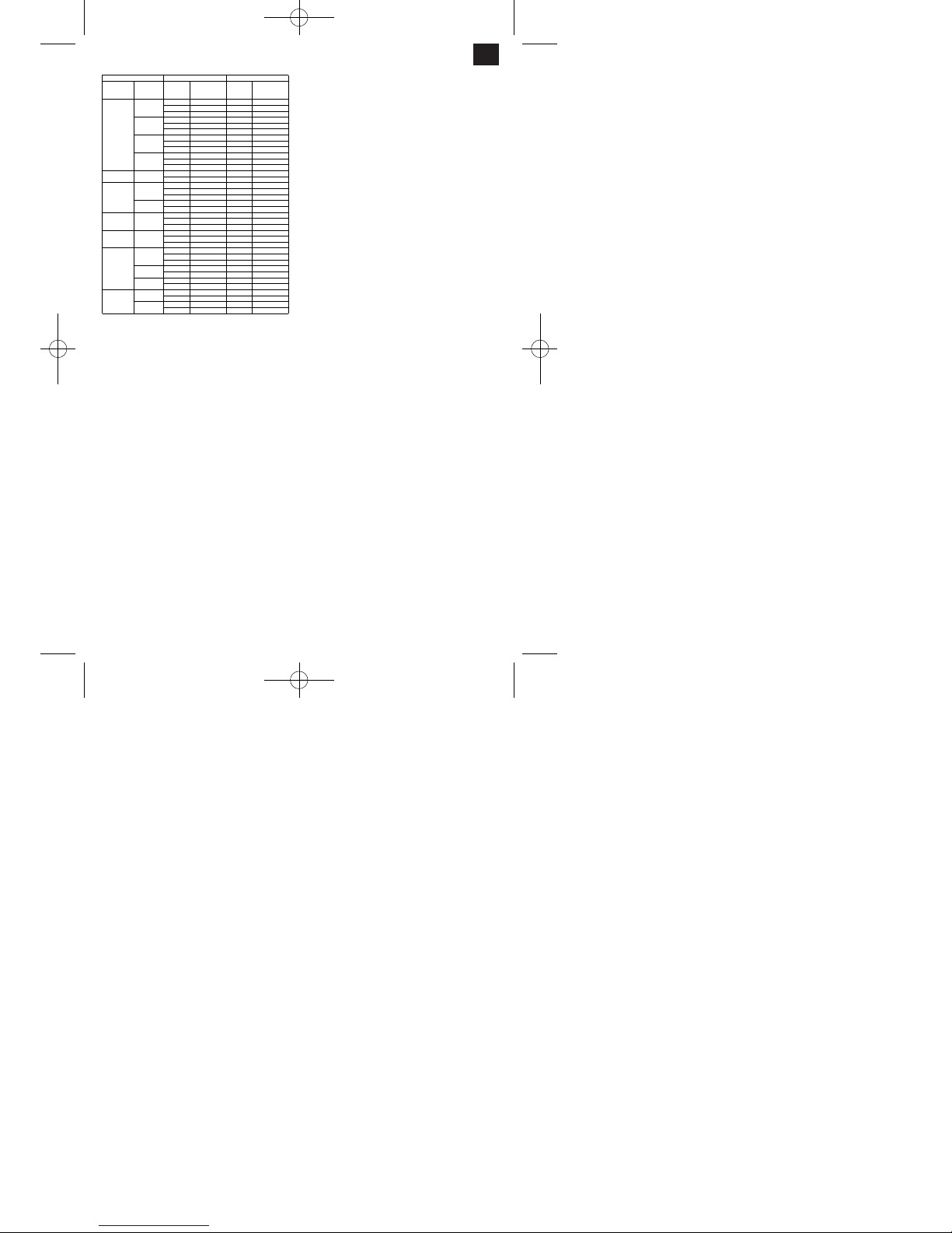
7.3 Tendre lʼoutil (fig. 3,4,6-8)
Dans la broche principale, il est exclusivement
autorisé dʼutiliser des outils, dispositifs de serrage ou
porte-outils avec cône Morse MK3 et filet femelle
M12 pour fixer à engagement positif. Il ne faut pas
utiliser de douilles de réduction !
7.3.1 Tendre les outils dans la broche principale
앬 Mettez la machine hors service et retirez la fiche
de contact !
앬 Retirez le recouvrement de la broche (15)
앬 Nettoyez et dégraissez la tige conique (18) et la
broche (4).
앬 Enfichez alors la tige conique (18) dans la douille
de la broche principale (4). Attention : afin dʼéviter
des blessures, prenez la fraise avec un chiffon !
앬 Pour fixer la broche principale, enfoncez la broche
de fixation (17) latéralement dans le manchon de
broche.
앬 Serrez à fond la barre de traction (19) à lʼaide
dʼune clé à fourche (SN 10) pour fixer la tige conique. La barre de traction doit être vissée dans le
mandrin du cône avec env. 8 tours (dans le sens
des aiguilles dʼune montre). Important : bloquez
toujours lʼoutil ou le mandrin de perçage avec la
barre de traction afin dʼexclure un desserrage de
lʼoutil.
앬 Retirez à nouveau la broche de fixation (17).
앬 Enfichez à nouveau le recouvrement de la broche
(15).
7.3.2 Retirez lʼoutil de la broche principale :
앬 Mettez la machine hors service et retirez la fiche
de contact !
앬 Retirez le recouvrement de la broche (15)
앬 Pour fixer la broche principale, enfoncez la broche
de fixation (17) latéralement dans le manchon de
broche.
앬 Desserrez la barre de traction avec une clé à four-
che (SN 10) dans le sens contraire de celui des
aiguilles dʼune montre.
앬 Détachez précautionneusement la tige conique
(18) en tapotant sur la tige de traction (19) avec un
marteau en caoutchouc et retirez-la du manchon
de broche. Afin d’éviter des blessures, prenez la
fraise avec un chiffon!
앬 Placez à nouveau le recouvrement de la broche
(15).
7.3.3 Maniement du mandrin
앬 Dans le mandrin de perçage (9) il est uniquement
permis de monter des outils cylindriques au
diamètre de tige maximal indiqué. Utilisez uniquement un outil irréprochable et aiguisé. Nʼutilisez
aucun outil dont la tige est endommagée ou
encore déformée ou abîmée dʼune manière ou
dʼune autre. Employez uniquement des
accessoires ou appareils auxiliaires dûment auto
risés par le producteur.
앬 Introduisez complètement la tige de lʼoutil dans le
mandrin de perçage (9) et serrez à fond avec la
clé de mandrins fournie.
앬 Retirez à nouveau la clé de mandrins. Veillez à ce
que les outils soient bien fixés.
Attention: ne laissez pas la clé de mandrins
enfoncée. Risque de blessure par la clé
catapultée.
7.4 Tendre la pièce à usiner
Attention: les pièces à usiner doivent toujours être
bien tendues ! Ceci est important pour la sécurité de
fonctionnement et pour le résultat du travail. Si la
pièce à usiner nʼest pas assez fixée, elle peut être
arrachée et catapultée par la force dʼavancement.
Il est préférable dʼutiliser à cet effet un étau de
machines (non compris dans la livraison). A lʼaide
de vis tendeuses et de pierres à rainures, on peut
fixer fermement lʼétau de machines sur la table à
mouvements croisés de la machine. Avant de serrer
à fond définitivement les vis, il faut aligner lʼétau de
machines à lʼaide dʼun calibre à cadran en parallèle
exacte par rapport aux guidages de chariot.
On peut également utiliser des grilles de serrage
adéquates (non comprises dans la livraison) pour
fixer la pièce à usiner sur la table de la machine. Il
27
F
Matériau
Résistance à
la traction
Profondeur
de coupe a
[mm]
Vitesse de
coupe v [m/min]
Profondeur
de coupe a
[mm]
Vitesse de
coupe v [m/min]
0,5 70 - 50 1 200 - 150
3 50 - 30 6 100 - 70
10 30 - 20 10 70 - 50
0,5 45 - 30 1 150 - 110
3 30 - 20 6 80 - 55
10 18 - 12 10 55 - 35
0,5 30 - 20 1 110 - 75
3 20 - 15 6 55 - 35
10 18 - 10 10 35 - 25
- - 1 75 - 50
- - 3 50 - 30
- - 6 30 - 20
0,5 90 - 40 1 160 - 80
3 75 - 30 3 120 - 60
0,5 45 - 35 1 100 - 80
3 35 - 25 3 90 - 60
10 20 - 15 10 60 - 40
0,5 40 - 30 1 100 - 70
3 30 - 20 3 70 - 50
0,5 70 - 45 1 240 - 190
3 60 - 40 3 190 - 140
6 40 - 20 6 140 - 80
0,5 60 - 40 1 150 - 100
3 50 - 35 3 100 - 60
6 35 - 20 6 70 - 45
0,5 180 - 160 0,5 700 +
3 160 - 140 3 600 - 400
6 140 - 120 6 500 - 250
1 140 - 100 1 400 - 200
6 120 - 80 6 300 - 150
- - 1 200 - 120
--6150 - 50
3 150 - 100 3 450 - 350
6 120 - 70 6 350 - 250
3 100 - 55 3 400 - 300
6 55 - 35 6 30 - 200
Métal durAcier rapide
Cuivre
Alliages
200 - 400
400 - 800
Aluminium
Alliages
60 - 320
320 - 440
440 +
Fonte
malléable
noire
350
Fonte
malléable
blanche
350 - 400
Acier de
décolletage
700
Acier moulé
avec
graphite à
lamelles
200
200 - 400
Acier de
construction
gén.; acier
pour outils;
acier de
cémentation
et acier de
traitement;
acier moulé
500 - 700
700 - 900
900 - 1100
1100 - 1400
Anleitung_BT_MR_550_SPK7:_ 18.12.2007 15:45 Uhr Seite 27
Page 28

faut alors veiller à ce que les grilles aient la bonne
taille afin dʼassurer une bonne fixation des pièces à
usiner.
7.5 Avance (Fig. 7, 8)
Tous les mouvements dʼavance doivent être réalisés
à la main.
7.5.1 Avance normale de la tête de fraisage
(fig. 1, 2, 9)
앬 Tirez le tourniquet (14) de lʼavance complètement
hors de la machine vers lʼextérieur.
앬 On peut alors approcher rapidement lʼoutil de la
pièce à usiner à lʼaide du tourniquet.
앬 On utilise lʼavance normale pour réaliser des
perçages.
앬 La butée de profondeur (12) peut limiter la profon-
deur de perçage ou de coupe en sens y.
앬 Pour ce faire, desserrez la poignée de blocage
(20) sur la butée de profondeur (12)
앬 Réglez la butée de profondeur sur la position
désirée et resserrez à fond la poignée de blocage
(20).
앬 La position dʼavance peut être lue sur la
graduation (21).
7.5.2 Avance précise de la tête de fraisage
(fig. 1, 9)
앬 Poussez le tourniquet (14) en direction de la tête
de fraisage (1) de manière que les dents de
lʼaccouplement à griffes (27) sʼencrantent.
앬 La fraise peut à présent être positionnée avec pré-
cision à lʼaide de la roue de réglage pour avance
précise (7).
앬 Un anneau gradué correspond à 0,02 mm de tra-
jet de déplacement de la table.
앬 Lorsque la profondeur de coupe désirée est
réglée, la tête de fraisage (1) doit être fixée à
lʼaide du levier de serrage (28) respectif.
7.5.3 Avance de la table à mouvements croisés
(fig. 8)
앬 La table à mouvements croisés (2) de la machine
peut être déplacée à la main dans deux axes perpendiculaires lʼun à lʼautre (X ; Y).
앬 Lʼavance pendant le fraisage se fait en actionnant
la manivelle (10 ; 11).
앬 On peut régler la position zéro du trajet de dépla-
cement grâce à lʼanneau gradué sur la manivelle.
앬 Un anneau gradué correspond à 0,02 mm de tra-
jet de déplacement de la table.
앬 Si un axe X ou Y de la table nʼest pas employé, il
est recommandé de le bloquer à lʼaide du levier
de serrage respectif.
7.6 Orientation de la tête de fraisage
(fig. 1, 2, 11-13)
Pour fraiser des chanfreins ou des rainures en V, on
peut orienter la tête de fraisage vers la gauche et
vers la droite de 45° à chaque fois.
Attention : assurez-vous avant le réglage que la
machine est bien vissée sur sa surface de travail !
앬 Mise hors service de la machine.
앬 Bien maintenir la tête de la machine (1) dʼune
main afin dʼéviter quʼelle ne bascule.
앬 Desserrez lʼécrou de fixation (13) avec la clé à
fourche (SN 36).
앬 0° Déverrouiller le blocage (23) en tirant.
앬 Réglez lʼangle désiré sur lʼéchelle dʼangle (24).
앬 Resserrez à nouveau lʼécrou de fixation (13) à
fond.
7.7 Ajuster les guidages dʼonglets (fig. 14)
En cas dʼutilisation fréquente, lʼécart entre la surface
coulissante de la glissière longitudinale et
transversale tout comme de la tête de fraisage peut
changer. Pour garantir un fonction et un mouvement
impeccables, il est nécessaire de rajuster les
guidages dʼonglets environ 1 fois par an.
앬 Desserrez les contre-écrous (25)
앬 rajustez les vis dʼajustage (26) de manière que la
pression exercée sur le guidage dʼonglet soit
régulière sur chaque vis dʼajustage.
앬 Maintenez les vis dʼajustage (26) en position à
lʼaide dʼune clé à six pans creux (3 mm) et resserrez les contre-écrous (25).
앬 Astuce : serrez toujours les vis dʼajustage en com-
mençant de lʼextérieur de façon uniforme afin
dʼobtenir un réglage homogène.
8. Traitement
8.1 Perçage et fraisage en profondeur
앬 introduisez le mandrin de perçage et lʼoutil comme
indiqué au chap. 7.2 et bloquez avec la barre de
traction.
앬 Serrez à fond le mandrin de perçage à lʼaide de la
clé de mandrins.
앬 Réglez la vitesse de rotation correcte (voir chap.
7.1-7.2)
앬 Tendez bien la pièce à usiner à lʼaide dʼun étau à
machine ou à lʼaide dʼune grille de serrage.
앬 Mettez la table à mouvements croisés (2) dans sa
position désirée dans les sens X et Y.
앬 Réglez la butée de profondeur (voir chap. 7.5.1) et
veillez à ce que lʼoutil nʼeffleure pas la pièce à
usiner.
앬 Retirez les objets que vous nʼemployez plus de la
28
F
Anleitung_BT_MR_550_SPK7:_ 18.12.2007 15:45 Uhr Seite 28
Page 29

zone de travail.
앬 Mettez la machine en circuit et réglez la vitesse de
rotation correcte de la broche via le sélecteur de
vitesse.
앬 Effectuez le perçage ou le fraisage. Nota : percez
dʼabord avec un foret plus petit puis continuez
avec un plus grand. Retirez le foret de la pièce à
usiner plusieurs fois pendant le forage, ainsi le
trou restera sans copeaux.
앬 La profondeur de perçage ou de coupe dépend du
réglage de la butée de profondeur (12)
앬 Après achèvement du travail, remettez la tête de
fraisage en position supérieure et mettez la
machine hors service.
앬 Nettoyez et huilez, le cas échéant, la machine et
lʼoutillage de prise de pièce.
8.1.1 Chanfreiner et perçage à centrer
Veillez à chanfreiner avec une petite vitesse de
coupe et une avance basse, alors que le perçage à
centrer doit être réalisé avec une grande vitesse de
coupe et une avance basse.
8.2 Fraiser en bout
앬 Tendez le mandrin et lʼoutil (voir chap. 7.1) et blo-
quez avec la barre de traction (19).
앬 Serrez à fond le mandrin à lʼaide de la clé de
mandrins.
앬 Réglez la plage de vitesse correcte
(voir chap. 7.1-7.2)
Attention: ne modifiez pas les plages de vitesse
(L et H) lorsque la broche fonctionne !
앬 Tendez bien la pièce à usiner à lʼaide dʼun étau à
machine ou à lʼaide dʼune grille de serrage.
앬 Mettez la table de travail dans sa position désirée
dans les sens X et Y
앬 Réglez la butée de profondeur (voir chap. 7.4.1) et
veillez à ce que lʼoutil nʼeffleure pas la pièce à
usiner.
앬 Retirez les objets que vous nʼemployez plus de la
zone de travail.
앬 Mettez la machine en circuit et réglez la vitesse de
rotation désirée de la broche via le sélecteur de
vitesse (6).
앬 Effectuez la fraise. Réglez pour ce faire la table à
mouvements croisés à lʼaide de la manivelle en
sens X et Y. (voir 7.5.3)
앬 Après achèvement du travail, mettez la machine
hors service et remettez la tête de fraisage (1) en
position supérieure.
앬 Nettoyez et huilez, le cas échéant, la machine et
lʼoutillage de prise de pièce.
Après utilisation de la machine, il faut nettoyer à
nouveau la table de travail et la huiler.
9. Soins et entretien
Retirez toujours la fiche secteur avant tous soins
et travaux de maintenance ! La machine doit faire
lʼeffet dʼune maintenance régulière (en fonction de la
fréquence dʼutilisation). Les travaux de maintenance
doivent être précisément documentés.
앬 Gardez les tiges coniques et les fraises propres.
앬 Pour les protéger, mettez directement les fraises
de préférence dans une boîte lorsque vous ne les
utilisez pas.
앬 Contrôlez le bon fonctionnement du circuit électri-
que entier (interrupteurs, fiches, contacts, etc.).
앬 Afin dʼéviter de plus grands dommages et blessu-
res, veuillez contacter notre service après-vente
en cas de pannes dépassants la maintenance
normale. Vous trouverez lʼadresse dans le bulletin
de garantie suivant.
앬 Contrôlez si la tête de la fraiseuse se déplace
facilement et veillez quʼelle ne se détache pas.
앬 Vérifiez si la broche ne dépasse pas.
앬 Contrôlez la bonne tenue de toutes les unions vis-
sées.
9.1 Lubrification
Il faut régulièrement dégraisser et graisser la
machine afin de garantir constamment de bons
résultats de travail et de protéger la machine contre
la corrosion. Répartissez lʼhuile de graissage ou la
graisse lubrifiante de façon uniforme avec un
pinceau ou un chiffon.
Points de graissage et lubrifiants :
Toutes les pièces de machine nues :
huile de graissage
Crémaillère sur colonne :
huile de graissage
Table de la machine :
huile de graissage
Mécanique de lʼavance de précision :
huile de graissage
Broche dʼavance de glissière longitudinale :
huile de graissage
Broche dʼavance de glissière transversale :
huile de graissage
Dispositif de guidage prismatique de la tête de
fraisage : graisse lubrifiante
Coussinet de pivotement de la tête de fraisage :
graisse lubrifiante
Dispositif de guidage prismatique de la glissière
transversale : graisse lubrifiante
Dispositif de guidage prismatique de la glissière
longitudinale : graisse lubrifiante
29
F
Anleitung_BT_MR_550_SPK7:_ 18.12.2007 15:45 Uhr Seite 29
Page 30

10. Remplacement de la ligne de
raccordement réseau
Si la ligne de raccordement réseau de cet appareil
est endommagée, il faut la faire remplacer par le
producteur ou son service après-vente ou par une
personne de qualification semblable afin dʼéviter tout
risque.
11. Nettoyage, maintenance et
commande de pièces de rechange
Retirez la fiche de contact avant tous travaux de
nettoyage.
11.1 Nettoyage
Maintenez les dispositifs de protection, les fentes
à air et le carter de moteur aussi propres (sans
poussière) que possible. Frottez lʼappareil avec
un chiffon propre ou soufflez dessus avec de lʼair
comprimé à basse pression.
Nous recommandons de nettoyer lʼappareil
directement après chaque utilisation.
Nettoyez lʼappareil régulièrement à lʼaide dʼun
chiffon humide et un peu de savon. Nʼutilisez
aucun produit de nettoyage ni détergeant ; ils
pourraient endommager les pièces en matières
plastiques de lʼappareil. Veillez à ce quʼaucune
eau nʼentre à lʼintérieur de lʼappareil.
11.2 Maintenance
Aucune pièce à lʼintérieur de lʼappareil nʼa besoin
de maintenance.
11.3 Commande de pièces de rechange :
Pour les commandes de pièces de rechange,
veuillez indiquer les références suivantes:
Type de lʼappareil
No. dʼarticle de lʼappareil
No. dʼidentification de lʼappareil
No. de pièce de rechange de la pièce requise
Vous trouverez les prix et informations actuelles à
lʼadresse www.isc-gmbh.info
12. Mise au rebut et recyclage
Lʼappareil se trouve dans un emballage permettant
dʼéviter les dommages dus au transport. Cet
emballage est une matière première et peut donc
être réutilisé ultérieurement ou être réintroduit dans
le circuit des matières premières.
Lʼappareil et ses accessoires sont en matériaux
divers, comme par ex. des métaux et matières
plastiques. Eliminez les composants défectueux
dans les systèmes dʼélimination des déchets
spéciaux. Renseignez-vous dans un commerce
spécialisé ou auprès de lʼadministration de votre
commune !
30
F
Anleitung_BT_MR_550_SPK7:_ 18.12.2007 15:45 Uhr Seite 30
Page 31

31
I
Staccate la spina dalla presa di corrente!
Attenzione! I lavori su apparecchiature elettriche devono venire eseguiti esclusivamente da un
elettricista specializzato!
Attenzione! Azionate la leva di selezione per l’intervallo di regime soltanto a macchina
ferma!
Attenzione! Prima di accendere l’apparecchio si deve aprire la protezione ripiegabile del
mandrino di serraggio!
“Avvertimento – Per ridurre il rischio di lesioni leggete le istruzioni per lʼuso”
Indossate gli occhiali protettivi.
Scintille createsi durante il lavoro o schegge, trucioli e polveri scaraventate fuori dallʼapparecchio
possono causare la perdita della vista.
Anleitung_BT_MR_550_SPK7:_ 18.12.2007 15:45 Uhr Seite 31
Page 32

Attenzione!
Nellʼusare gli apparecchi si devono rispettare diverse
avvertenze di sicurezza per evitare lesioni e danni.
Quindi leggete attentamente queste istruzioni per
lʼuso/le avvertenze di sicurezza. Conservate bene le
informazioni per averle a disposizione in qualsiasi
momento. Se date lʼapparecchio ad altre persone,
consegnate queste istruzioni per lʼuso/le avvertenze
di sicurezza insieme allʼapparecchio. Non ci
assumiamo alcuna responsabilità per incidenti o
danni causati dal mancato rispetto di queste
istruzioni e delle avvertenze di sicurezza.
1. Descrizione dellʼelettroutensile
(Fig. 1-4)
1. Testa per fresare
2. Tavola a guide ortogonali
3. Montante della macchina
4. Mandrino di lavoro
5. Leva del cambio
6. Selettore del numero di giri
7. Rotella di regolazione per avanzamento di
precisione
8. Interruttore ON/OFF
9. Mandrino per punte da trapano a corona dentata
10. Manovella per slitta trasversale
11. Manovella per slitta longitudinale
12. Asta di profondità
13. Dado di fissaggio per regolazione
dellʼinclinazione
14. Volantino a croce
15. Copertura del mandrino
16. Protezione ripiegabile contro i trucioli
2. Elementi forniti
앬 Trapanantrice e fresatrice
앬 Chiave del mandrino per punte da trapano
앬 Chiave a gancio
앬 Spina di fissaggio
앬 Utensili
3. Uso corretto
Questa macchina serve per la perforazione, la
fresatura frontale ed in profondità di piccoli pezzi
(dimensioni max.: 300 mm x 200 mm x 200 mm) di
metallo, plastica o materiali simili. Con il mandrino
per punte da trapano a corona dentata in dotazione
di serie si devono usare solo utensili di foratura e
fresatura con un gambo cilindrico di max. 16 mm.
Nel caso di lavorazione di metalli (ST37) il diametro
dellʼutensile non dovrebbe essere superiore a 13
mm. Inoltre è possibile inserire direttamente nel
mandrino di lavoro anche utensili con gambo conico
(MK3). Questa trapanatrice e fresatrice è adatta solo
per lʼuso privato e non deve essere impiegata per
attività professionali. La macchina deve venire usata
solamente per lo scopo a cui è destinata. Ogni altro
tipo di uso che esuli da quello previsto non è un uso
conforme.
Lʼutilizzatore o lʼoperatore, e non il costruttore, è
responsabile dei danni e delle lesioni di ogni tipo che
ne derivino. Anche il rispetto delle avvertenze di
sicurezza nonché delle istruzioni di montaggio e
delle avvertenze per lʼuso contenute nelle istruzioni
per lʼuso rientra nellʼuso corretto. Le persone che
usano la macchina e chi si occupa della
manutenzione devono conoscere bene
lʼelettroutensile e gli eventuali pericoli. Inoltre si
devono rispettare scrupolosamente le norme
antinfortunistiche vigenti. Si devono inoltre rispettare
le altre regole generali di medicina di lavoro e di
sicurezza.
Tenete presente che i nostri apparecchi non sono
stati costruiti per lʼimpiego professionale, artigianale
o industriale. Non ci assumiamo alcuna garanzia
quando lʼapparecchio viene usato in imprese
commerciali, artigianali o industriali, o in attività
equivalenti.
Le modifiche alla macchina escludono
completamente ogni responsabilità del costruttore e
ogni danno che ne derivi. Anche se la macchina
viene usata in modo corretto non si possono
escludere completamente determinati fattori di
rischio residuo. Visto il funzionamento e la struttura
degli elettroutensili si possono presentare i seguenti
punti.
앬 Contatto col mandrino autocentrante nella zona
non coperta.
앬 Lʼimpigliarsi nelle parti rotanti (pericolo di lesioni)
앬 Pezzi da lavorare e loro frammenti scagliati
allʼingiro.
앬 Refrigeranti e lubrificanti dannosi per la salute.
Accertatevi che lo smaltimento sia ecologico.
앬 Contatto con parti rotanti nella zona non coperta.
Pericolo di lesioni!
앬 Attenzione! Pericolo di lesioni! Togliete sempre
subito la chiave del mandrino autocentrante e non
lasciatela mai infilata!
앬 Pericolo di lesioni a causa della fresa che non
viene utilizzata.
32
I
Anleitung_BT_MR_550_SPK7:_ 18.12.2007 15:45 Uhr Seite 32
Page 33

앬 Lesioni agli occhi a causa di trucioli e altre
schegge scagliate allʼingiro. Indossate assolutamente occhiali protettivi!
4. Avvertenze importanti
Prima della messa in esercizio leggete
attentamente le istruzioni per lʼuso ed osservate
le avvertenze di sicurezza. Con lʼaiuto di queste
istruzioni per lʼuso, familiarizzate con
lʼapparecchio, il suo uso corretto e le avvertenze
di sicurezza. Tenete le istruzioni per lʼuso sempre
a portata di mano in modo che lʼutilizzatore le
possa sempre consultare.
앬 È assolutamente necessario indossare dei dispo-
sitivi individuali di protezione per ogni lavoro con
la macchina.
앬 Indossate sempre degli occhiali protettivi per
evitare delle lesioni agli occhi.
앬 Se avete i capelli lunghi, portate assolutamente
una retina o un berretto adatto.
앬 Portate indumenti da lavoro aderenti.
앬 Nellʼutensile in movimento potrebbero impigliarsi
maniche o simili.
앬 Per togliere i trucioli usate un raschietto adatto.
Non togliere mai i trucioli a mano nuda.
앬 Con la macchina spenta togliete i trucioli con uno
scopino o un pennello.
앬 È permesso usare la macchina solo a persone di
età superiore ai 18 anni che siano pratiche del suo
impiego e funzionamento.
앬 Ai giovani di età tra i 16 e i 18 anni il lavoro è
consentito soltanto sotto la supervisione di un
adulto.
앬 Prima di iniziare a lavorare controllate che il
dispositivo di protezione funzioni correttamente.
앬 Non sottoponete la macchina a sollecitazioni
eccessive. Si lavora in modo migliore e più sicuro
nel range di prestazioni indicato.
앬 Usate lʼutensile corretto e fate attenzione che gli
utensili (utensile da tornio, punte del trapano) non
siano spuntati o rotti.
앬 Tenete il cavo sempre dietro lʼapparecchio.
앬 Proteggete il cavo dal calore, dallʼolio e dagli
spigoli vivi.
앬 Staccate la spina dalla presa di corrente in caso di
riparazioni e di lavori di manutenzione e se non
usate la macchina.
앬 I lavori su dispositivi elettrici devono venire
eseguiti esclusivamente da un elettricista
specializzato. Si devono utilizzare solo ricambi
originali.
앬 Un posto di lavoro pulito facilita il lavoro. Fate
attenzione a quello che fate. Apprestatevi a lavor
are con prudenza.
앬 Fate attenzione che il piano di appoggio sia in
grado di sopportare il peso della macchina e che
sia abbastanza solido per non provocare
vibrazioni.
앬 Le parti lucide sono ben lubrificate in fabbrica per
proteggerle dalla corrosione. Pulite la macchina
prima della messa in esercizio con un detergente
ecologico adatto.
앬 Attenzione! Chiudete la copertura di protezione
del mandrino autocentrante prima di accendere la
macchina.
앬 Con la macchina non si devono lavorare materiali
dannosi per la salute o che producono polveri,
come per es. legno, teflon, ecc.
앬 Non usate la macchina nelle vicinanze di liquidi o
gas infiammabili.
앬 Usate la macchina solo in locali adatti e non
tenete lʼapparecchio in un luogo umido o bagnato.
앬 Accertatevi che ci sia una buona illuminazione
mentre lavorate.
앬 Non usate il cavo per estrarre la spina dalla presa
di corrente.
앬 Fate attenzione che il pezzo da lavorare sia ben
serrato mentre lavorate. Serrate sempre il pezzo
da lavorare con una morsa a vite per macchine o
con lʼaiuto di staffe di serraggio.
앬 Usate solamente utensili affilati ed in perfetto
stato.
앬 In caso di situazioni pericolose o di anomalie
tecniche spegnete subito la macchina e staccate
la spina dalla presa di corrente!
앬 In caso di danni non si deve più lavorare con la
macchina e la spina deve essere staccata dalla
presa di corrente!
앬 Attenzione! Si devono utilizzare solo utensili ed
accessori autorizzati dal costruttore. Lʼuso di pezzi
non autorizzati può rappresentare un rischio di
lesioni per voi!
앬 Tenete la vostra zona di lavoro in ordine e pulita. Il
disordine nella zona di lavoro può causare
infortuni.
앬 Portare occhiali protettivi. In caso di lavoro con
forte sviluppo di polvere si deve inoltre usare una
maschera antipolvere o per il viso.
앬 Togliete le chiavi ed altri utensili prima di iniziare a
lavorare.
33
I
Anleitung_BT_MR_550_SPK7:_ 18.12.2007 15:45 Uhr Seite 33
Page 34

5. Caratteristiche tecniche
Tensione nominale 230 V ~ / 50 Hz
Potenza nominale 550 W S3 50% 400W S1
Intervallo di regime (L) basso 50 -1.100 min
-1
Intervallo di regime (H) alto 120 -2.500 min
-1
Cono morse nel mandrino MK 3
Diametro max. di foratura 16 mm
Diametro fresa a candela 13 mm
Diametro fresa frontale 30 mm
Tavola a guide ortogonali 410 x 112 mm
Spostamento max. tavola in x 250 mm
Spostamento max. tavola in y 100 mm
Corsa max. mandrino 220 mm
Inclinazione s/d -45° - +45°
Livello di pressione acustica LPA 83 dB(A)
Tipo di protezione IP 23
Peso 62 kg
Modalità operativa S3 (esercizio periodico
intermittente)
La macchina può essere usata per un determinato
intervallo di tempo (durata relativa di inserimento in
% della durata del ciclo) con potenza nominale. Poi
la macchina deve rimanere ferma per un intervallo di
tempo (tempo di pausa) per non surriscaldarsi. La
durata di ciclo è composta dalla durata della
sollecitazione e dalla durata della pausa. Durante
lʼinattività fra i cicli la macchina non si raffredda più a
temperatura ambiente. La durata di ciclo è di 10 min
se non viene indicato altrimenti.
6. Messa in esercizio
Attenzione!
앬 Staccate la spina dalla presa di corrente prima di
ogni lavoro di montaggio o di impostazione.
앬 Per evitare danni dovuti al trasporto la macchina
deve essere trasportata solo in posizione verticale, meglio ancora se nella confezione originale!
앬 Fate attenzione al peso della macchina! Il peso
netto della macchina è di 62 kg. Usate un mezzo
di trasporto adatto che sia in grado di sostenere il
carico della macchina. Se non ci dovesse essere
a disposizione un mezzo di trasporto, sollevate
con cautela la macchina in modo da non causare
danni alle persone e alle cose.
앬 Proteggete la macchina dallʼumidità e dalla
pioggia.
앬 Lʼinstallazione e lʼuso della macchina sono
consentiti solo in locali asciutti ed arieggiati. Il
range di temperature per lʼesercizio della
macchina dovrebbe essere fra +15° e +40°.
앬 Il mandrino portautensile e la punta della fresa
sono fissati a sufficienza?
앬 Controllate se ci sono delle parti della macchina
che eventualmente si sono allentate.
앬 È stato scelto lʼintervallo di regime corretto?
앬 La macchina ed il mezzo di serraggio sono puliti e
privi di trucioli?
앬 Controllate che le viti di fissaggio della pinza a tre
morsetti siano serrate bene e che il mandrino di
lavoro si possa ruotare facilmente a mano.
앬 Prima della messa in esercizio devono essere
montate tutte le coperture ed i dispositivi di
sicurezza.
앬 Il mandrino autocentrante deve potersi muovere
liberamente.
앬 Prima di azionare lʼinterruttore accertatevi che
tutto sia montato correttamente e che le parti
mobili possano muoversi liberamente.
앬 Prima di inserire la spina nella presa di corrente
assicuratevi che i dati sulla targhetta di identificazione corrispondano a quelli di rete.
앬 Montate le impugnature della manovella fornite
(Fig. 5).
6.2 Installazione
Mettete la macchina su un piano di appoggio liscio
(banco di lavoro ecc.).
Importante: la macchina deve essere avvitata
saldamente con il piano di appoggio tramite quattro
viti. A tale scopo usate i quattro fori di fissaggio della
piastra di base della macchina.
Accertatevi che ci sia spazio sufficiente per spostare
la tavola a guide ortogonali e per il cambiamento di
inclinazione.
Fate attenzione che il piano di appoggio sia
sufficientemente stabile per sostenere il peso della
macchina (ca. 62 kg).
Le parti lucide sono lubrificate in fabbrica per
proteggerle dalla corrosione. Pulite la macchina
prima della messa in esercizio con un detergente
ecologico adatto. Non usate detergenti che
potrebbero rovinare la vernice della macchina e
durante la pulizia arieggiate bene il locale. Al termine
della pulizia oliate di nuovo la macchina con olio
lubrificante neutro!
Attenzione: olio, grasso e detergenti sono inquinanti
e perciò devono essere smaltiti in modo corretto non gettateli nei rifiuti domestici!
6.3 Allacciamento alla rete / interruttore
La macchina deve venire usata solo con corrente
monofase di 230 Volt / 50 Hz. Il circuito di corrente di
alimentazione deve essere protetto con
massimo 16 A.
34
I
Anleitung_BT_MR_550_SPK7:_ 18.12.2007 15:45 Uhr Seite 34
Page 35

6.3.1 Accensione della macchina (Fig. 3)
Prima di accendere la macchina si deve abbassare
la protezione ripiegabile contro i trucioli (16).
Per accendere la macchina si deve premere il tasto
verde (I).
Se la spia di controllo verde (a) è illuminata si può
inserire la macchina per mezzo del selettore (6) e
impostare il numero di giri desiderato.
Se si illumina anche la spia di controllo arancione (b)
si deve prima portare il selettore del numero di giri
(6) in posizione “0” e la spia gialla si spegne. Poi si
può quindi impostare il numero di giri desiderato
sulla macchina e questa si avvia.
6.3.2 Spegnimento della macchina
Spegnete la macchina premendo il tasto rosso “O” o
il tasto di “ARRESTO DI EMERGENZA” (c) e
scollegatelo dalla rete staccando la spina dalla presa
di corrente.
7. Uso e impostazione
Attenzione: tutte le impostazioni della macchina
devono essere eseguite solo con la spina staccata
dalla presa di corrente.
7.1 Impostazione del regime (Fig. 3-4)
Tramite la leva del cambio (5) sul lato della macchina
si può scegliere fra due intervalli di regime.
Posizione anteriore (L) per lʼintervallo di regime
da 50 a 1100 min
-1
Posizione posteriore (H) per lʼintervallo di regime
da 120 a 2500 min
-1
Attenzione: non modificare gli intervalli di regime (L
e H) con mandrino in movimento! Il numero di giri
può essere regolato in continuo nellʼambito del
relativo intervallo. La regolazione di precisione del
numero di giri avviene tramite il selettore di
regime (6)
7.2 Regime corretto / Velocità di taglio
La scelta della velocità di taglio corretta influisce
molto sulla vita utile dellʼutensile e sul risultato del
lavoro. Deve essere scelta in funzione del materiale.
La velocità di taglio corretta si ottiene scegliendo il
livello giusto di regime.
7.2.1 Perforazione
Regola generale: quanto più piccoli sono i fori e
quanto più morbido è il materiale, tanto maggiore è il
livello di regime.
La lista sotto riportata vi aiuta nella scelta del regime
corretto per i diversi materiali.
I valori di regime riportati sono solamente indicativi.
Per lʼimpostazione del regime si veda il Cap. 7.1.
Ø boor Grijs gietijzer Staal Ijzer Aluminium Brons
3 2550 1600 2230 9500 8000
4 1900 1200 1680 7200 6000
5 1530 955 1340 5700 4800
6 1270 800 1100 4800 4000
7 1090 680 960 4100 3400
8 960 600 840 3600 3000
9 850 530 740 3200 2650
10 765 480 670 2860 2400
11 700 435 610 2600 2170
12 640 400 560 2400 2000
13 590 370 515 2200 1840
14 545 340 480 2000 1700
16 480 300 420 1800 1500
18 425 265 370 1600 1300
20 380 240 335 1400 1200
22 350 220 305 1300 1100
25 305 190 270 1150 950
7.2.2 Fresatura
Il regime si può calcolare nel modo seguente:
n = v / ( x d )
n = numero di giri in min
-1
v = velocità di taglio in m/min
d = diametro dellʼutensile in m
= 3,14
Per i valori delle velocità e delle profondità massime
di taglio per il rispettivo materiale si veda la lista
seguente o un manuale con le tabelle.
35
I
Anleitung_BT_MR_550_SPK7:_ 18.12.2007 15:45 Uhr Seite 35
Page 36

7.3 Serraggio degli utensili (Fig. 3, 4, 6-8)
Nel mandrino di lavoro si devono usare
esclusivamente utensili, dispositivi di serraggio o
sedi dʼutensile con cono morse MK3 e filetto interno
M12 per il fissaggio ad accoppiamento di forma. Non
devono essere usate bussole di riduzione!
7.3.1 Serraggio degli utensili nel mandrino
di lavoro
앬 Spegnete la macchina e staccate la spina dalla
presa di corrente!
앬 Togliete la copertura del mandrino (15).
앬 Pulite e sgrassate il gambo conico (18) ed il
mandrino (4).
앬 Quindi inserite il gambo conico (18) nella bussola
del mandrino di lavoro (4). Attenzione: per evitare
delle lesioni la fresa dovrebbe venire toccata con
un panno!
앬 Per fissare il mandrino di lavoro inserite la spina di
fissaggio (17) lateralmente nella bussola del
mandrino.
앬 Per fissare il gambo conico serrate la barra di
trazione (19) con una chiave fissa (n. 10). La
barra di trazione deve essere avvitata con ca. 8
giri (in senso orario) nella spina del cono.
Importante: fissate sempre bene lʼutensile o il
mandrino per punte da trapano con la barra di tra
zione per evitare che lʼutensile si stacchi.
앬 Togliete di nuovo la spina di fissaggio (17).
앬 Montate di nuovo la copertura del mandrino (15).
7.3.2 Smontaggio dellʼutensile dal mandrino
di lavoro
앬 Spegnete la macchina e staccate la spina dalla
presa di corrente!
앬 Togliete la copertura del mandrino (15).
앬 Per fissare il mandrino di lavoro inserite la spina di
fissaggio (17) lateralmente nella bussola del
mandrino.
앬 Allentate la barra di trazione con una chiave fissa
(n. 10) in senso antiorario.
앬 Allentate cautamente il gambo conico (18) dando
dei colpi leggeri alla barra di trazione (19) con un
martello di gomma e toglietelo dalla bussola del
mandrino. Per evitare delle lesioni la fresa
dovrebbe venire toccata con un panno!
앬 Mettete di nuovo la copertura del mandrino (15).
7.3.3 Uso del mandrino per punte da trapano
앬 Nel mandrino per punte da trapano (9) si devono
serrare solo utensili cilindrici con il diametro
massimo indicato per il gambo. Usate solo utensili
affilati ed in perfetto stato. Non utilizzate utensili
deformati o rovinati o con il gambo danneggiato.
Utilizzate soltanto gli accessori o apparecchi
supplementari autorizzati dal produttore.
앬 Inserite completamente il gambo dellʼutensile nel
mandrino per punte da trapano (9) e serratelo con
la chiave in dotazione.
앬 Estraete di nuovo la chiave. Controllate che gli
utensili siano ben serrati.
Attenzione: non lasciate inserita la chiave. Se
viene scagliata intorno può provocare lesioni.
7.4 Serraggio dei pezzi da lavorare
Attenzione: I pezzi da lavorare devono sempre
venire fissati saldamente! Questo è importante per la
sicurezza dʼesercizio e il risultato di lavoro. Se il
pezzo da lavorare non è ben fissato, può venire
strappato dalla forza di avanzamento della fresa e
scaraventato via.
Lʼutensile più adatto a questo scopo è una morsa a
vite per macchine (non compresa negli elementi
forniti). Mediante viti di serraggio e chiocciole, la
morsa a vite per macchine può venire fissata
saldamente sulla tavola a guide ortogonali della
macchina.Prima di serrare definitivamente le viti, la
morsa a vite per macchina deve venire allineata
esattamente alle guide delle slitte mediante un
minimetro.
Possono anche venire usate delle staffe di
serraggio idonee (non comprese negli elementi
forniti) per fissare il pezzo da lavorare sulla tavola
della macchina. In tal caso si deve fare attenzione
alle giuste dimensioni delle staffe di serraggio per
36
I
Materiale
Resistenza
alla trazione
Profondità
di taglio
a [mm]
Velocità di taglio
v [m/min]
Profondità di
taglio
a [mm]
Velocità di taglio
v [m/min]
0,5 70 - 50 1 200 - 150
3 50 - 30 6 100 - 70
10 30 - 20 10 70 - 50
0,5 45 - 30 1 150 - 110
3 30 - 20 6 80 - 55
10 18 - 12 10 55 - 35
0,5 30 - 20 1 110 - 75
3 20 - 15 6 55 - 35
10 18 - 10 10 35 - 25
- - 1 75 - 50
- - 3 50 - 30
- - 6 30 - 20
0,5 90 - 40 1 160 - 80
3 75 - 30 3 120 - 60
0,5 45 - 35 1 100 - 80
3 35 - 25 3 90 - 60
10 20 - 15 10 60 - 40
0,5 40 - 30 1 100 - 70
3 30 - 20 3 70 - 50
0,5 70 - 45 1 240 - 190
3 60 - 40 3 190 - 140
6 40 - 20 6 140 - 80
0,5 60 - 40 1 150 - 100
3 50 - 35 3 100 - 60
6 35 - 20 6 70 - 45
0,5 180 - 160 0,5 700 +
3 160 - 140 3 600 - 400
6 140 - 120 6 500 - 250
1 140 - 100 1 400 - 200
6 120 - 80 6 300 - 150
- - 1 200 - 120
- - 6 150 - 50
3 150 - 100 3 450 - 350
6 120 - 70 6 350 - 250
3 100 - 55 3 400 - 300
6 55 - 35 6 30 - 200
Metallo duroAcciaio rapido
Leghe di rame
200 - 400
400 - 800
Leghe di
alluminio
60 - 320
320 - 440
440 +
Ghisa malleabile
nera
350
Ghisa malleabile
bianca
350 - 400
Acciaio
automatico
700
Ghisa con
grafite lamellare
200
200 - 400
Acciaio da
costruzione;
acciaio per
utensili; acciaiao
per insert e
bonfica; acciaio
colato
500 - 700
700 - 900
900 - 1100
1100 - 1400
Anleitung_BT_MR_550_SPK7:_ 18.12.2007 15:45 Uhr Seite 36
Page 37

garantire che il pezzo da lavorare sia ben serrato.
7.5 Avanzamento (Fig. 7, 8)
Tutti i movimenti di avanzamento devono venire
eseguiti a mano.
7.5.1 Avanzamento normale della testa
per fresare (Fig. 1, 2, 9)
앬 Tirate il volantino a croce (14) dellʼavanzamento
verso lʼesterno, allontanandolo dalla macchina.
앬 Ora lʼutensile può venire avvicinato velocemente
al pezzo da lavorare mediante il volantino a croce.
앬 Lʼavanzamento normale viene utilizzato per
lʼesecuzione dei fori.
앬 Tramite lʼasta di profondità (12) può venire limitata
la profondità di perforazione o di fresatura in
direzione z.
앬 A tale scopo allentate la manopola di arresto (20)
sullʼasta di profondità (12).
앬 Regolate lʼasta di profondità sulla posizione
desiderata e serrate di nuovo la manopola di
arresto (20).
앬 La posizione di avanzamento viene indicata dalla
scala (21).
7.5.2 Avanzamento di precisione della testa
per fresare (Fig. 1, 9)
앬 Spingete il volantino a croce (14) in direzione della
testa per fresare (1) in modo che i denti
dellʼinnesto a denti frontali (27) ingranino.
앬 La fresa può quindi venire posizionatain maniera
esatta per lʼavanzamento di precisione (7)
mediante la rotella di regolazione.
앬 Una tacca sullʼanello graduato corrisponde a 0,02
mm di spostamento della tavola.
앬 Se la profondità di fresatura desiderata è
impostata, la testa per fresare (1) deve venire
fissata mediante la rispettiva leva di serraggio
(28).
7.5.3 Avanzamento della tavola a guide
ortogonali (Fig. 8)
앬 La tavola (2) della macchina può venire spostata
manualmente su due assi (X;Y) che si trovano in
posizione ortogonale lʼuno rispetto allʼaltro.
앬 Lʼavanzamento durante la fresatura viene
eseguito azionando le manovelle (10;11).
앬 Tramite lʼanello graduato sulle manovelle si può
impostare la posizione zero dello spostamento.
앬 Una tacca sullʼanello graduato corrisponde a 0,02
mm di spostamento della tavola.
앬 Se un asse di spostamento (X o Y) della tavola
non viene usato, si consiglia di serrarlo mediante
la rispettiva leva di serraggio (22).
7.6 Orientamento della testa per fresare
(Fig. 1, 2, 11-13)
Per la fresatura di smussi o scanalature a V la testa
per fresare può venire orientata a sinistra e a destra
rispettivamente a 45°.
Attenzione: assicuratevi prima dellʼimpostazione
che la macchina sia ben avvitata sulla superficie di
lavoro!
앬 Spegnete la macchina.
앬 Tenete bene la testa della macchina (1) con una
mano per evitare che si ribalti.
앬 Allentate il dado di fissaggio (13) con una chiave
fissa (n. 36).
앬 Sbloccate lʼarresto 0° (23) estraendolo.
앬 Impostate lʼinclinazione desiderata sulla relativa
scala (24).
앬 Serrate di nuovo il dado di fissaggio (13).
7.7 Regolazione delle guide per tagli obliqui
(Fig. 14)
In caso di uso frequente, può cambiare la distanza
tra le superfici di scorrimento della slitta longitudinale
e trasversale nonché della testa per fresare. Per
garantire un perfetto funzionamento e movimento, le
guide per tagli obliqui dovrebbero venire regolate
circa una volta allʼanno.
앬 Allentate i controdadi (25).
앬 Regolate le viti di regolazione (26) in modo che la
pressione esercitata sulla guida per tagli obliqui
sia uniforme per ogni vite di regolazione.
앬 Tenete in posizione la vite di regolazione (26)
mediante una brugola (3 mm) e serrate di nuovo i
controdadi (25).
앬 Consiglio: serrate le viti di regolazione sempre in
modo regolare da due lati per mantenere
unʼimpostazione uniforme.
8. Lavorazione
8.1 Perforazione e fresatura in profondità
앬 Impiegate il mandrino per punte da trapano e
lʼutensile come descritto nel cap. 7.2 e serrateli
con la barra di trazione.
앬 Serrate il mandrino per punte da trapano
mediante la chiave.
앬 Impostate il giusto numero di giri
(vedi cap. 7.1-7.2))
앬 Serrate bene il pezzo da lavorare mediante una
morsa a vite per macchine o delle staffe di
serraggio.
앬 Portate la tavola a guide ortogonali (2) in direzione
(X e Y) nella posizione desiderata.
앬 Impostate lʼasta di profondità (vedi cap. 7.5.1) e
37
I
Anleitung_BT_MR_550_SPK7:_ 18.12.2007 15:45 Uhr Seite 37
Page 38

fate attenzione che lʼutensile non tocchi il pezzo
da lavorare.
앬 Togliete dalla zona di lavoro gli oggetti che non
servono più.
앬 Accendete la macchina ed impostate il giusto
numero di giri del mandrino con il selettore del
numero di giri (6).
앬 Esecuzione del lavoro di perforazione o di
fresatura. Avvertenza: in caso di fori grandi si
dovrebbe eseguire una prima perforazione con
una punta da trapano piccola. Estraete ogni tanto
la punta del trapano dal pezzo da lavorare durante
lʼesecuzione della perforazione affinché il foro
rimanga privo di trucioli.
앬 La profondità di perforazione o di fresatura risulta
dallʼimpostazione dellʼasta di profondità (12).
앬 Al termine del lavoro rimettete la testa per fresare
nella posizione superiore e spegnete la macchina.
앬 Pulite la macchina e il dispositivo di serraggio
oliandoli se necessario.
8.1.1 Svasatura e perforazione di centraggio
Fate attenzione che la svasatura deve venire
eseguita a bassa velocità di taglio e ad avanzamento
lento mentre la perforazione di centraggio viene
eseguita ad alta velocità di taglio ed avanzamento
lento.
8.2 Fresatura frontale
앬 Serrate il mandrino di serraggio e lʼutensile (vedi
cap. 7.1) e fissateli con la barra di trazione (19).
앬 Serrate il mandrino di serraggio mediante la relati
va chiave.
앬 Impostate il giusto numero di giri
(vedi cap. 7.1-7.2)
Attenzione: non modificate gli intervalli di regime
(L e H) con il mandrino in movimento!
앬 Tendete bene il pezzo da lavorare mediante una
morsa a vite per macchine o delle staffe di
serraggio.
앬 Portate il piano di lavoro in direzione (X e Y) nella
posizione desiderata.
앬 Impostate lʼasta di profondità (vedi cap. 7.4.1) e
fate attenzione che lʼutensile non tocchi il pezzo
da lavorare.
앬 Togliete dalla zona di lavoro gli oggetti che non
servono più.
앬 Accendete la macchina ed impostate il numero di
giri desiderato del mandrino con il selettore del
numero di giri (6).
앬 Eseguite il lavoro di fresatura. A tale scopo,
spostate la tavola a guide ortogonali in direzione X
e Y mediante le manovelle. (vedi 7.5.3)
앬 Al termine del lavoro, spegnete la macchina e
rimettete la testa per fresare (1) nella posizione
superiore.
앬 Pulite la macchina e il dispositivo di serraggio oli
andoli se necessario.
Dopo lʼuso della macchina il piano di lavoro deve
venire ripulito e oliato.
9. Manutenzione e cura
Prima di ogni lavoro di cura e manutenzione si
deve staccare la spina dalla presa di corrente! È
necessario eseguire la manutenzione della macchina
ad intervalli regolari (a seconda della frequenza
dʼuso). I lavori di manutenzione devono essere
documentati in modo preciso.
앬 Tenete puliti i gambi conici e le frese.
앬 Per proteggere le frese di tipo identico
consigliamo di conservarle in una scatola se non
vengono usate.
앬 Verificate che tutto il circuito di corrente di
alimentazione (interruttori, connettori, contatti,
ecc.) funzioni correttamente.
앬 Per evitare gravi danni e lesioni, in caso di guasti
che vanno oltre una normale manutenzione,
rivolgetevi al nostro servizio assistenza clienti.
Troverete lʼindirizzo del servizio assistenza nel
seguente certificato di garanzia.
앬 Controllate che la testa della fresa giri liberamente
e fate attenzione che non si sia allentata.
앬 Controllate che il mandrino non vibri
eccessivamente.
앬 Controllate che tutti i collegamenti a vite siano ben
serrati.
9.1 Lubrificazione
Per garantire sempre dei buoni risultati di lavoro e
per proteggere la macchina contro la corrosione,
essa deve venire lubrificata e ingrassata ad intervalli
regolari. Distribuite lʼolio o il grasso lubrificante
uniformemente con un pennello o un panno che non
perda peluzzi.
Punti di lubrificazione e lubrificanti
Tutte le parti lucide della macchina:
olio lubrificante
Barra dentata sulla colonna:
olio lubrificante
Tavola della macchina:
olio lubrificante
Meccanismo dellʼavanzamento
di precisione: olio lubrificante
Mandrino di avanzamento slitta
longitudinale: olio lubrificante
Mandrino di avanzamento slitta
trasversale: olio lubrificante
38
I
Anleitung_BT_MR_550_SPK7:_ 18.12.2007 15:45 Uhr Seite 38
Page 39

Guida prismatica testa per
fresare: grasso lubrificante
Cuscinetto girevole testa per
fresare: grasso lubrificante
Guida prismatica slitta
trasversale: grasso lubrificante
Guida prismatica slitta
longitudinale: grasso lubrificante
10. Sostituzione del cavo di
alimentazione
Se il cavo di alimentazione di questo apparecchio
viene danneggiato deve essere sostituito dal
produttore, dal suo servizio di assistenza clienti o da
una persona al pari qualificata al fine di evitare
pericoli.
11. Pulizia, manutenzione e ordinazione
dei pezzi di ricambio
Prima di qualsiasi lavoro di pulizia staccate la spina
dalla presa di corrente.
11.1 Pulizia
Tenete il più possibile i dispositivi di protezione,
le fessure di aerazione e la carcassa del motore
liberi da polvere e sporco. Strofinate
lʼapparecchio con un panno pulito o soffiatelo
con lʼaria compressa a pressione bassa.
Consigliamo di pulire lʼapparecchio subito dopo
averlo usato.
Pulite lʼapparecchio regolarmente con un panno
asciutto ed un poʼ di sapone. Non usate
detergenti o solventi perché questi ultimi
potrebbero danneggiare le parti in plastica
dellʼapparecchio. Fate attenzione che non possa
penetrare dellʼacqua nellʼinterno
dellʼapparecchio.
11.2 Manutenzione
Allʼinterno dellʼapparecchio non si trovano altre
parti sottoposte ad una manutenzione qualsiasi.
11.3 Ordinazione di pezzi di ricambio:
Volendo commissionare dei pezzi di ricambio, si
dovrebbe dichiarare quanto segue:
modello dellʼapparecchio
numero dellʼarticolo dellʼapparecchio
numero dʼident. dellʼapparecchio
numero del pezzo di ricambio del ricambio
necessitato
Per i prezzi e le informazioni attuali si veda
www.isc-gmbh.info
12. Smaltimento e riciclaggio
Lʼapparecchio si trova in una confezione per evitare i
danni dovuti al trasporto. Questo imballaggio
rappresenta una materia prima e può perciò essere
utilizzato di nuovo o riciclato.
Lʼapparecchio e i suoi accessori sono fatti di
materiali diversi, per es. metallo e plastica.
Consegnate i pezzi difettosi allo smaltimento di rifiuti
speciali. Per informazioni rivolgetevi ad un negozio
specializzato o allʼamministrazione comunale!
39
I
Anleitung_BT_MR_550_SPK7:_ 18.12.2007 15:45 Uhr Seite 39
Page 40

40
E
¡Desenchufar el aparato!
¡Atención! ¡Los trabajos en instalaciones eléctricas sólo deberán ser llevados a cabo por
electricistas!
¡Atención! Activar la palanca selectora para la gama de revoluciones sólo con la
máquina parada!
¡Atención! ¡Antes de conectar, desplegar la protección del mandril abatible!
“Aviso - Leer el manual de instrucciones para reducir cualquier riesgo de sufrir daños”
Llevar gafas de protección.
Durante el trabajo, la expulsión de chispas, astillas, virutas y polvo por el aparato pueden
provocar pérdida de vista.
Anleitung_BT_MR_550_SPK7:_ 18.12.2007 15:45 Uhr Seite 40
Page 41

¡Atención!
Al usar aparatos es preciso tener en cuenta una serie
de medidas de seguridad para evitar lesiones o
daños. Por este motivo, es preciso leer atentamente
este manual de instrucciones/advertencias de
seguridad. Guardar esta información
cuidadosamente para poder consultarla en cualquier
momento. En caso de entregar el aparato a terceras
personas, será preciso entregarles, asimismo, el
manual de instrucciones/advertencias de seguridad.
No nos hacemos responsables de accidentes o
daños provocados por no tener en cuenta este
manual y las instrucciones de seguridad.
1. Descripción del aparato (fig. 1-4)
1. Cabezal portafresa
2. Mesa de cruz
3. Columna de la máquina
4. Husillo de trabajo
5. Palanca de engranaje
6. Selector de revoluciones
7. Rueda de ajuste para avance de precisión
8. Interruptor ON/OFF
9. Portabrocas de corona dentada
10. Manivela para carrito transversal
11. Manivela para carrito longitudinal
12. Tope de profundidad
13. Tuerca de sujeción para regulación de
inclinación
14. Torniquete
15. Cubierta del husillo
16. Protección abatible contra virutas
2. Volumen de entrega
앬 Taladro-fresadora
앬 Llave portabrocas
앬 Llave con salientes para tuercas cilíndricas
앬 Clavija posicionadora
앬 Herramienta
3. Uso adecuado
Esta máquina está indicada para taladrar, fresar y
fresar frontalmente piezas pequeñas (dimensiones
máx.: 300 mm x 200 mm x 200 mm) de metal,
plástico o materiales similares. Con el portabrocas
en corona dentada de serie sólo se pueden utilizar
herramientas de taladro-fresadora que tengan un
mango de conexión cilíndrico de máx. 16 mm. En los
trabajos con metal (ST37), el diámetro de la
herramienta no debe ser superior a 13 mm.
Asimismo, es posible alojar herramientas con mango
de conexión cónica (MK3) directamente en el husillo
de trabajo. Este taladro-fresadora sólo está indicado
para su uso doméstico y no se podrá utilizar con
fines industriales. Utilizar la máquina sólo en los
casos que se indican explícitamente como de uso
adecuado. Cualquier otro uso no será adecuado.
En casos de uso inadecuado, el fabricante no se
hace responsable de los daños o lesiones de
cualquier tipo, el responsable es el usuario u
operario de la máquina. Otra de las condiciones de
un uso adecuado es la observancia de las
instrucciones de seguridad, así como de las
instrucciones de montaje y de servicio del manual de
instrucciones. Las personas encargadas de operar y
mantener la máquina deben estar familiarizadas con
la misma y haber recibido información sobre todos
los posibles peligros. Además, es imprescindible
respetar en todo momento las disposiciones vigentes
en materia de prevención de accidentes. Es preciso
observar también cualquier otro reglamento general
en el ámbito de la medicina laboral y técnicas de
seguridad.
Tener en consideración que nuestro aparato no está
indicado para un uso comercial, industrial o en taller.
No asumiremos ningún tipo de garantía cuando se
utilice el aparato en zonas industriales, comerciales
o talleres, así como actividades similares.
El fabricante no se hace responsable de los cambios
realizados en la máquina por parte del operario, ni
de los daños que se puedan derivar por este motivo.
Existen determinados factores de riesgo que no se
pueden descartar por completo, incluso haciendo un
uso adecuado de la máquina. El diseño y atributos
de la máquina pueden conllevar los riesgos
siguientes:
앬 Contacto del mandril en una zona no cubierta.
앬 Contacto con piezas giratorias (peligro de acci-
dente)
앬 Rebote de las piezas con las que se está traba-
jando o de algunas de sus partes.
앬 Refrigerante y lubricante perjudiciales para la
salud. Eliminarlos de manera ecológica
앬 Entrada en contacto con componentes giratorios
en zonas desprotegidas. ¡Peligro de accidente!
앬 ¡Atención! ¡Peligro de sufrir accidentes! Volver a
sacar las llaves del mandril tras cada uso, ¡no
dejarlas nunca introducidas!
앬 Peligro de accidente por la herramienta de fre-
sado que no se está utilizando.
41
E
Anleitung_BT_MR_550_SPK7:_ 18.12.2007 15:45 Uhr Seite 41
Page 42

앬 Peligro de sufrir heridas en los ojos por virutas o
astillas que salgan disparadas. ¡Ponerse gafas de
protección!
4. Advertencias importantes
Antes de la puesta en marcha, leer
detenidamente las instrucciones de uso y
observar las advertencias de seguridad. Utilizar
este manual para familiarizarse con el aparato,
su uso correcto y las advertencias de seguridad
pertinentes. Guardar las instrucciones de uso
en un lugar de fácil acceso.
앬 Es preciso llevar equipamiento de protección
personal siempre que se utilice la máquina.
앬 Llevar siempre gafas de protección para evitar
sufrir daños oculares.
앬 Si se tiene el cabello largo, recogerlo con una
redecilla o llevar una gorra adecuada.
앬 Ponerse ropa de trabajo ajustada.
앬 La herramienta giratoria podría pillar mangas, etc.
앬 Para eliminar la virutas, utilizar una herramienta
adecuada. No retirarlas nunca simplemente conlas manos.
앬 Retirar las virutas cuando la máquina esté apa-
gada, preferentemente con una escobilla o un
pincel.
앬 Sólo les está permitido el uso de la máquina a
personas mayores de 18 años que estén
familiarizados con el manejo de la misma.
앬 A los jóvenes de 16 a 18 años de edad sólo les
está permitido el uso de la máquina bajo la supervisión de un adulto.
앬 Antes de comenzar los trabajos, comprobar que el
dispositivo de protección funcione correctamente.
앬 No sobrecargar la máquina. Se trabajará mejor y
de forma más segura si se hace con la potencia
indicada.
앬 Utilizar la herramienta adecuada y comprobar que
las herramientas (cuchilla de corte, broca) estén
afiladas y en perfecto estado.
앬 Mantener el cable alejado de la parte trasera del
aparato en todo momento. Es preciso proteger el
cable del calor, del aceite y de cantos vivos.
앬 Desenchufar la máquina antes de realizar trabajos
de reparación, mantenimiento y cuando no se
esté utilizando.
앬 ¡Los trabajos en instalaciones eléctricas sólo
deberán ser llevados a cabo por un electricista!
Sólo se pueden utilizar piezas originales.
앬 Es conveniente mantener el lugar de trabajo
limpio. Es preciso estar atento a lo que se hace
mientras se trabaja con la máquina. Actuar
siempre de forma razonable.
앬 Asegurarse de que la base pueda soportar el
peso de la máquina y sea suficientemente estable
para que no se produzcan vibraciones.
앬 En la fábrica se han engrasado todas las piezas al
descubierto para protegerlas de la corrosión.
Limpiar la máquina antes de la puesta en marcha
con un producto de limpieza adecuado y
ecológico.
앬 ¡Atención! Cerrar la cubierta de protección del
mandril antes de conectar la máquina.
앬 No está permitido taladrar ni fresar materiales
nocivos para la salud o que produzcan gran
cantidad de polvo, como la madera, el teflón, etc.
앬 No utilizar la máquina cerca de líquidos o gases
inflamables.
앬 Trabajar con la máquina sólo en recintos adecua-
dos, evitando hacerlo en lugares húmedos o
mojados.
앬 La zona de trabajo debe estar siempre bien
iluminada.
앬 No tirar del cable para desenchufar la máquina.
앬 Asegurarse de que la pieza esté bien sujeta a la
hora de realizar trabajos. Sujetar la pieza siempre
con un tornillo de banco para máquinas o con
ayuda de abrazaderas.
앬 Utilizar exclusivamente herramientas afiladas y
limpias.
앬 Desconectar y desenchufar inmediatamente la
máquina cuando se produzcan situaciones
peligrosas o averías técnicas.
앬 En caso de estar dañada, no se podrá seguir
trabajando con la máquina y se deberá desen
chufar.
앬 ¡Atención! Sólo se pueden utilizar herramientas y
accesorios autorizados por el fabricante. El uso
de piezas no autorizadas puede conllevar el
peligro de sufrir accidentes.
앬 Mantener limpia y ordenada la zona de trabajo. El
desorden puede conllevar accidentes.
앬 Ponerse gafas de protección. En los trabajos que
generen gran cantidad de polvo será preciso
utilizar un mascarilla.
앬 Antes de empezar a trabajar, retirar la llave
portabrocas y cualquier otra herramienta.
42
E
Anleitung_BT_MR_550_SPK7:_ 18.12.2007 15:45 Uhr Seite 42
Page 43

5. Características técnicas
Tensión nominal 230 V ~ / 50 Hz
Potencia nominal 550 W S3 50% 400 W S1
Gama de revoluciones (L) baja 50–1.100 r.p.m.
Gama de revoluciones(H) baja 120–2.500 r.p.m.
Cono Morse en husillo MK 3
Diámetro de taladro máx. 16 mm
Diámetro fresa de punta 13 mm
Diámetro fresa frontal 30 mm
Mesa de cruz 410 x 112 mm
Ajuste máx. de mesa en x 250 mm
Ajuste máx. de mesa en y 100 mm
Elevación máx. de husillo 220 mm
Ajuste angular izda./dcha. -45° - +45°
Nivel de presión acústica LPA 83 dB(A)
Tipo de protección IP 23
Peso 62 kg
Régimen de funcionamiento S3 (régimen
periódico de funcionamiento discontinuo):
Es posible poner la máquina en funcionamiento con
potencia nominal durante un periodo determinado de
tiempo (régimen permanente relativo en % del ciclo
de trabajo). Después, la máquina deberá pararse por
un periodo de tiempo (pausa) para no
sobrecalentarla. El ciclo de trabajo está formado por
el tiempo de solicitación y la duración de las pausas.
Durante las paradas entre los ciclos, la máquina no
se vuelve a enfriar a la temperatura ambiente.
Mientras no se indique lo contrario, la duración de un
ciclo es de 10 min.
6. Puesta en marcha
¡Atención!
앬 Retirar el enchufe de la toma de contacto antes
de llevar a cabo cualquier operación de montaje y
regulación.
앬 ¡Para evitar daños producidos por el transporte,
transportar la máquina en vertical y
preferentemente en su embalaje original!
앬 ¡Tener en cuenta el peso de la máquina! El peso
neto de la máquina es de 62 kg. Utilizar un medio
de transporte adecuado que pueda soportar el
peso de la máquina. En caso de que no haya
ninguno disponible, elevar la máquina con
cuidado para no producir daños ni a personas ni a
la máquina.
앬 Proteger el aparato de la humedad y de la lluvia.
앬 Almacenar y utilizar la máquina exclusivamente
en recintos secos y bien ventilados. La temper-
atura óptima para el funcionamiento debe ser
entre +15°C y +40°C.
앬 ¿Se encuentran bien sujetos el mandril y la fresa?
앬 Controlar si se ha soltado alguna pieza de la
máquina.
앬 ¿Se ha seleccionado la gama de revoluciones
correcta?
앬 ¿Están tanto la máquina como la pieza de
sujeción limpias de virutas?
앬 Comprobar que los tornillos de fijación del mandril
de tres mordazas estén bien apretados y si es
fácil girar con la mano el husillo de trabajo.
앬 Antes de la puesta en marcha es preciso montar
todas las cubiertas y los dispositivos de
seguridad.
앬 El mandril debe funcionar sin ningún tipo de
obstáculos.
앬 Antes de conectar la máquina, asegurarse de que
todo esté bien montado y de que las piezas
móviles se muevan con suavidad.
앬 Antes de conectar la máquina, asegurarse de que
los datos de la placa de características coincidan
con los datos de la red eléctrica.
앬 Montar los mangos de manivela suministrados
(fig. 5).
6.2 Ubicación
Colocar la máquina sobre una superficie plana
(banco de trabajo, etc.).
¡Importante! La máquina debe estar fijada a la base
con cuatro tornillos. Para ello, hacer uso de las
perforaciones de fijación en el tablero base de la
máquina.
Asegurarse de que haya suficiente espacio para
mover la mesa de cruz y para regular la inclinación.
Asegurarse de que la base de la máquina es
suficientemente estable para soportar su peso
(aprox. 62 kg).
Todas las piezas al descubierto han sido engrasadas
para protegerlas de la corrosión. Limpiar la máquina
antes de la puesta en marcha con un producto de
limpieza adecuado y ecológico. No utilizar productos
de limpieza que puedan deteriorar la pintura de la
máquina y asegurarse de que durante la limpieza se
disponga de suficiente ventilación. Tras la limpieza
de la máquina, volver a engrasarla ligeramente con
aceite lubricante exento de ácidos.
Atención: Tanto el aceite como la grasa y los
productos de limpieza son perjudiciales para el
medio ambiente, por lo tanto, se deben eliminar de
forma ecológica, ¡no tirarlos a la basura doméstica!
6.3 Tensión de red/interruptor
La máquina sólo puede funcionar con corriente
monofásica 230 voltios / 50 Hz. El circuito ha de
estar protegido con 16 A como máximo.
43
E
Anleitung_BT_MR_550_SPK7:_ 18.12.2007 15:45 Uhr Seite 43
Page 44

6.3.1 Conectar la máquina (fig. 3)
Antes de la conexión, la protección contra virutas
(16) se debe encontrar plegada hacia abajo.
Para conectarla, presionar la tecla verde (I).
Si el piloto de control verde (a) se ilumina, la
máquina se puede conectar mediante el selector de
velocidad (6) para ponerla a la velocidad deseada.
Si, adicionalmente, se ilumina el piloto de control
naranja (b), se deberá poner el selector de velocidad
(6) primero en la posición “0” para que el piloto se
vuelva a apagar. Seguidamente, seleccionar la
velocidad deseada y la máquina funciona.
6.3.2 Desconectar el aparato
Desconectar la máquina presionando la tecla roja
“O” o la “TECLA PARO DE EMERGENCIA” (c) y
desenchufarla.
7. Manejo y ajuste
Atención: Los ajustes se deberán realizar
exclusivamente cuando la máquina esté
desconectada.
7.1 Ajuste de las revoluciones (fig. 3-4)
Se pueden seleccionar dos gamas de velocidades
mediante la palanca de engranaje (5) situada en el
lateral de la máquina.
Posición delantera (L) para la gama de revoluciones
50 a 1100 r.p.m.
Posición posterior (H) para la gama de revoluciones
120 a 2500 r.p.m.
Atención: ¡No
modificar nunca las gamas de
revoluciones (L y H) cuando el husillo se encuentre
en funcionamiento! La velocidad se puede regular de
forma continua dentro de la gama de revoluciones.
El ajuste de precisión de las revoluciones se lleva a
cabo mediante el selector (6).
7.2 Revoluciones correctas/velocidad de corte
La elección de la velocidad de corte correcta afecta
enormemente tanto a la vida útil de la herramienta
como al resultado del trabajo. La velocidad
adecuada depende del material. La velocidad de
corte correcta se obtiene al elegir adecuadamente
las revoluciones.
7.2.1 Taladrar
Regla general: Cuanto más pequeños sean los
orificios y más blando el material, mayor será la
velocidad.
La lista que figura más abajo sirve de ayuda a la
hora de seleccionar la velocidad adecuada para los
distintos materiales.
Las velocidades indicadas son sólo datos de
referencia.
Ajuste de las revoluciones, véase cap. 7.1
Ø Broca Fundición gris Acero Hierro Aluminio Bronce
3 2550 1600 2230 9500 8000
4 1900 1200 1680 7200 6000
5 1530 955 1340 5700 4800
6 1270 800 1100 4800 4000
7 1090 680 960 4100 3400
8 960 600 840 3600 3000
9 850 530 740 3200 2650
10 765 480 670 2860 2400
11 700 435 610 2600 2170
12 640 400 560 2400 2000
13 590 370 515 2200 1840
14 545 340 480 2000 1700
16 480 300 420 1800 1500
18 425 265 370 1600 1300
20 380 240 335 1400 1200
22 350 220 305 1300 1100
25 305 190 270 1150 950
7.2.2 Fresar
Las revoluciones se calculan de la siguiente forma:
n = v / ( x d )
n = r.p.m.
v = velocidad de corte en m/min
d = diámetro de la herramienta en m
= 3,14
Los valores para las velocidades de corte y las
profundidades máximas de corte para cada material
figuran en el listado a continuación o en un manual
de tablas.
44
E
Anleitung_BT_MR_550_SPK7:_ 18.12.2007 15:45 Uhr Seite 44
Page 45

7.3 Sujeción de las herramientas (fig. 3,4,6-8)
En el husillo de trabajo sólo se pueden utilizar
herramientas, dispositivos de sujeción o
alojamientos de herramientas con cono Morse MK3
y rosca interior M12 para fijación de bloqueo. ¡No
está permitido utilizar casquillos reductores!
7.3.1 Sujeción de herramientas en el husillo de
trabajo
앬 ¡Desconectar y desenchufar la máquina!
앬 Retirar la cubierta del husillo (15).
앬 Limpiar y engrasar el vástago cónico (18) y el
husillo (4).
앬 Introducir el vástago cónico (18) en el manguito
del husillo de trabajo (4). Atención: ¡Para evitar
sufrir daños, coger la fresa con un trapo!
앬 Para fijar el husillo, introducir la clavija
posicionadora (17) lateralmente en el manguito
del husillo.
앬 Apretar la barra de tracción (19) para fijar el
vástago cónico con una llave de boca (SW10). La
barra de tracción se atornilla en el calibre macho
cónico dándole 8 vueltas (en sentido de las
agujas del reloj). Importante: Asegurar siempre la
herramienta o el portabrocas con la barra de
tracción para evitar que se suelte de forma
imprevista.
앬 Volver a retirar la clavija posicionadora (17).
앬 Volver a colocar la cubierta del husillo (15).
7.3.2 Retirar la herramienta del husillo de trabajo:
앬 ¡Desconectar y desenchufar la máquina!
앬 Retirar la cubierta del husillo (15).
앬 Para fijar el husillo, introducir la clavija
posicionadora (17) lateralmente en el manguito
del husillo.
앬 Soltar la barra de tracción con la llave de boca
(SW 10) en sentido contrario al de las agujas del
reloj.
앬 Soltar con cuidado el vástago cónico (18)
golpeándolo sobre una barra de tracción (19) con
una maza de goma y sacarlo del manguito del
husillo. ¡Para evitar sufrir daños, coger la fresa con
un trapo!
앬 Volver a colocar la cubierta del husillo (15).
7.3.3 Manejo del portabrocas
앬 En el portabrocas (9) deben colocarse sólo
herramientas cilíndricas con el diámetro de
vástago indicado. Emplear sólo una herramienta
en perfecto estado y afilada. No utilizar
herramientas que estén dañadas en el vástago o
presenten otro tipo de deformación o daño.
Utilizar exclusivamente accesorios o componentes autorizados por el fabricante.
앬 Introducir completamente el mango de conexión
de la herramienta en el portabrocas (9) y apretarlo
con la llave portabrocas.
앬 Volver a extraer la llave portabrocas. Asegurarse
de que la herramienta colocada esté bien sujeta.
Atención: No olvidar retirar la llave portabrocas.
Existe peligro de sufrir heridas si la llave portabro
cas sale disparada.
7.4 Sujeción de las piezas
Atención: ¡Las piezas deben encontrarse siempre
bien sujetas! Esto es importante para la seguridad
del funcionamiento y el resultado final. Si no se
encuentran bien sujetas, se corre el riesgo de que la
fuerza de avance de la fresa las expulse y salgan
disparadas.
Para ello, lo más indicado es un tornillo de banco
para máquinas (no incluido entre las piezas
suministradas). Con ayuda de tornillos de apriete y
piedras ranuradas se puede fijar bien el tornillo de
banco para máquinas a la mesa de cruz. Antes de
atornillar definitivamente, el tornillo de banco deberá
colocarse paralelamente a las guías de carro por
medio de una galga para cuadrantes.
También se pueden utilizar abrazaderas (no
incluidas en el volumen de entrega), para sujetar la
pieza a la mesa de la máquina. Comprobar que el
tamaño de las abrazaderas sea el adecuado para
asegurar que la pieza esté bien sujeta.
45
E
Material
Resistencia
a la tracción
Profundidad
de corte a
[mm]
Velocidad de
corte v [m/min]
Profundidad
de corte a
[mm]
Velocidad de
corte v [m/min]
0,5 70 - 50 1 200 - 150
3 50 - 30 6 100 - 70
10 30 - 20 10 70 - 50
0,5 45 - 30 1 150 - 110
3 30 - 20 6 80 - 55
10 18 - 12 10 55 - 35
0,5 30 - 20 1 110 - 75
3 20 - 15 6 55 - 35
10 18 - 10 10 35 - 25
- - 1 75 - 50
- - 3 50 - 30
- - 6 30 - 20
0,5 90 - 40 1 160 - 80
3 75 - 30 3 120 - 60
0,5 45 - 35 1 100 - 80
3 35 - 25 3 90 - 60
10 20 - 15 10 60 - 40
0,5 40 - 30 1 100 - 70
3 30 - 20 3 70 - 50
0,5 70 - 45 1 240 - 190
3 60 - 40 3 190 - 140
6 40 - 20 6 140 - 80
0,5 60 - 40 1 150 - 100
3 50 - 35 3 100 - 60
6 35 - 20 6 70 - 45
0,5 180 - 160 0,5 700 +
3 160 - 140 3 600 - 400
6 140 - 120 6 500 - 250
1 140 - 100 1 400 - 200
6 120 - 80 6 300 - 150
- - 1 200 - 120
- - 6 150 - 50
3 150 - 100 3 450 - 350
6 120 - 70 6 350 - 250
3 100 - 55 3 400 - 300
6 55 - 35 6 30 - 200
Metal duroAcero rápido
Aleaciones de
cobre
200 - 400
400 - 800
Aleaciones de
aluminio
60 - 320
320 - 440
440 +
Fundición
maleable negra
350
Fundición
maleable
blanca
350 - 400
Acero para
tornos
700
Hierro fundido
con grafito
laminar
200
200 - 400
Al. Acero de
construcción,
Acero para
herramientas,
Acero
cementado y
acero
templado y
revenido Acero
fundido
500 - 700
700 - 900
900 - 1100
1100 - 1400
Anleitung_BT_MR_550_SPK7:_ 18.12.2007 15:45 Uhr Seite 45
Page 46

7.5 Avance (fig. 7,8)
Todos los movimientos de avance se deben realizar
a mano.
7.5.1 Avance normal del cabezal portafresa
(fig. 1, 2, 9)
앬 Extraer completamente hacia fuera de la máquina
el torniquete (14) del avance.
앬 Gracias al torniquete, la herramienta se puede
insertar rápidamente en la pieza.
앬 El avance normal se utiliza para perforar.
앬 El tope en paralelo (12) permite delimitar la
profundidad de perforación o fresado en la
dirección z.
앬 Para ello, soltar la empuñadura de sujeción (20)
en el tope de profundidad (12).
앬 Ajustar el tope de profundidad en la posición
deseada y volver a apretar la empuñadura (20).
앬 La posición de avance aparece indicada en la
escala graduada (21).
7.5.2 Avance de precisión del cabezal portafresa
(fig. 1, 9)
앬 Empujar el torniquete (14) hacia el cabezal
portafresa (1) de tal forma que los dientes del
acoplamiento de garras (27) encajen entre sí.
앬 La fresa se puede colocar con exactitud mediante
la rueda de ajuste del avance de precisión (7).
앬 Cada división en el anillo graduado corresponde a
0,02 mm de avance de la mesa.
앬 Cuando se haya ajustado la profundidad de
fresado deseada, se debe fijar el cabezal
portafresa (1) con la palanca de apriete (28)
correspondiente.
7.5.3 Avance de la mesa de cruz (fig. 8)
앬 La mesa de cruz (2) de la máquina se puede
mover manualmente en 2 ejes perpendiculares
(X, Y).
앬 En el fresado, el avance se realiza por medio de
las manivelas (10, 11).
앬 La posición cero del trayecto de desplazamiento
se ajusta mediante el anillo graduado en la
manivela.
앬 Cada división en el anillo graduado corresponde a
0,02 mm del trayecto de desplazamiento de la
mesa.
앬 Cuando no se utilice un eje de desplazamiento (X
o Y) de la mesa, se recomienda sujetarlo con la
palanca de apriete (22).
7.6 Girar el cabezal portafresa (fig. 1, 2, 11-13)
Para fresar biselados o ranuras en V se puede girar
en 45° el cabezal portafresa hacia la izquierda o
derecha.
Atención: ¡Antes de realizar el ajuste, asegurarse
de que la máquina esté bien atornillada a la
superficie de trabajo!
앬 Desconectar el aparato.
앬 Sujetar bien con una mano el cabezal de la
máquina (1) para evitar que se vuelque.
앬 Soltar la tuerca de sujeción (13) con una llave de
boca (SW 36).
앬 Bloqueo a 0º (23), desbloquear extrayendo.
앬 Ajustar el ángulo de ataque deseado en la escala
angular (24).
앬 Volver a apretar la tuerca de sujeción (13).
7.7 Ajustar las guías de ingletes (fig. 14)
El uso frecuente de la máquina puede provocar un
cambio en la distancia entre las superficies de
deslizamiento de los carritos transversal y
longitudinal, así como del cabezal portafresa. Para
garantizar un funcionamiento y movimiento
adecuados, es preciso reajustar, al menos 1 vez al
año, las guías de ingletes.
앬 Soltar las contratuercas (25).
앬 Reajustar el tornillo de reglaje (26) de tal forma
que la presión ejercida en cada tornillo de la guía
de ingletes sea homogénea.
앬 Ayudado por una llave de hexágono interior (3
mm), mantener el tornillo de reglaje (26) en su
posición y volver a apretar las contratuercas (25).
앬 Consejo: Poner los tornillos de reglaje desde
fuera y apretarlos siempre a la vez por los dos
lados para que el ajuste sea homogéneo.
8. Trabajo con la máquina
8.1 Taladrar y fresar
앬 Colocar el portabrocas y la herramienta según se
describe en el cap. 7.2 y asegurarlos con la barra
de tracción.
앬 Apretar el portabrocas con ayuda de la llave
portabrocas.
앬 Ajustar la velocidad adecuada
(véase cap. 7.1-7.2)
앬 Apretar bien la pieza mediante el tornillo de banco
para máquinas o la abrazadera.
앬 Poner la mesa de cruz (2) en la posición deseada
(dirección X o Y).
앬 Ajustar el tope de profundidad (véase cap. 7.5.1)
y comprobar que la herramienta no toque la pieza.
앬 Retirar de la zona de trabajo los objetos que ya no
se vayan a utilizar.
앬 Conectar la máquina y ajustar la velocidad
adecuada mediante el selector de
revoluciones (6).
앬 Taladrar o fresar. Advertencia: Cuando se
46
E
Anleitung_BT_MR_550_SPK7:_ 18.12.2007 15:45 Uhr Seite 46
Page 47

deseen realizar perforaciones de mayor tamaño,
taladrar primero con una broca pequeña. Durante
el taladrado, sacar la broca un par de veces de la
pieza para que salgan las virutas de la
perforación.
앬 La profundidad de la perforación o del fresado
depende del ajuste del tope de profundidad (12).
앬 Una vez finalizado el trabajo, volver a colocar el
cabezal portafresa en la posición superior y
desconectar la máquina.
앬 Limpiar la máquina y el dispositivo de sujeción y,
en caso necesario, engrasarlos.
8.1.1 Avellanar y taladrado centrado
Los trabajos de avellanado se realizan a baja
velocidad de corte y avance lento, mientras que el
centrado se realiza a alta velocidad de corte y
avance lento.
8.2 Fresado frontal
앬 Sujetar el mandril y la herramienta (véase cap.
7.1) y asegurarlos con la barra de tracción (19).
앬 Apretar el mandril con ayuda de la llave
portabrocas.
앬 Ajustar la gama de revoluciones adecuada (véase
cap. 7.1-7.2)
Atención: ¡No modificar nunca las gamas de
revoluciones (L y H) cuando el husillo se
encuentre en funcionamiento!
앬 Apretar bien la pieza mediante el tornillo de banco
o la abrazadera.
앬 Poner la mesa de trabajo en la posición deseada
(dirección X o Y).
앬 Ajustar el tope de profundidad (véase cap. 7.4.1)
y comprobar que la herramienta no toque la pieza.
앬 Retirar los objetos que no se vayan a utilizar más
de la zona de trabajo.
앬 Conectar la máquina y ajustar la velocidad desea
da mediante el selector de revoluciones (6).
앬 Proceder a fresar. Para ello, reajustar la mesa de
cruz mediante la manivela en la dirección X y Y.
(véase 7.5.3)
앬 Tras finalizar el trabajo, desconectar la máquina y
volver a poner el cabezal portafresa (1) en la
posición superior.
앬 Limpiar la máquina y el dispositivo de sujeción y,
en caso necesario, engrasarlos.
Tras utilizar la máquina, volver a limpiar y
engrasar la mesa de trabajo.
9. Cuidado y mantenimiento
¡Desenchufar la máquina antes de proceder a
realizar trabajos de cuidado y mantenimiento!
Realizar trabajos de mantenimiento de forma
periódica (dependiendo de la frecuencia de uso). Es
preciso documentar adecuadamente todos los
trabajos de mantenimiento.
앬 Mantener el vástago cónico y la fresa siempre
limpios.
앬 Para proteger la fresa cuando no se utilice, se
recomienda guardarla en una caja.
앬 Comprobar que todo el circuito eléctrico funcione
correctamente (interruptor, enchufe, contactos,
etc.).
앬 Para evitar daños graves, ponerse en contacto
con nuestro servicio de asistencia técnica siempre
que aparezcan averías que no se puedan subsanar con el mantenimiento normal. La dirección
del mismo figura en el certificado de garantía.
앬 Comprobar que el cabezal de la fresadora se
mueva fácilmente y asegurarse de que no se
haya soltado.
앬 Comprobar que el husillo no oscile demasiado.
앬 Comprobar que todas las atornilladuras estén
bien sujetas.
9.1 Lubricación
Para asegurar que el resultado final sea óptimo y
proteger la máquina contra la corrosión, es preciso
lubricarla y engrasarla regularmente. Repartir el
aceite o la grasa de lubricación de forma homogénea
con un pincel o con un paño que no desprenda
pelusa.
Puntos de lubricación y lubricantes:
Todas las piezas de la máquina sin pintar:
Aceite lubricante
Cremallera en la columna:
Aceite lubricante
Mesa de la máquina:
Aceite lubricante
Mecanismo del avance de precisión:
Aceite lubricante
Husillo de avance carrito longitudinal:
Aceite lubricante
Husillo de avance carrito transversal:
Aceite lubricante
Guía prismática cabezal portafresa:
Grasa lubricante
Rodamiento giratorio cabezal portafresa:
Grasa lubricante
Guía prismática carrito transversal:
Grasa lubricante
Guía prismática carrito longitudinal:
Grasa lubricante
47
E
Anleitung_BT_MR_550_SPK7:_ 18.12.2007 15:45 Uhr Seite 47
Page 48

10. Cambio del cable de conexión a la
red eléctrica
Cuando el cable de conexión a la red de este
aparato esté dañado, deberá ser sustituido por el
fabricante o su servicio de asistencia técnica o por
una persona cualificada para ello, evitando así
cualquier peligro.
11. Mantenimiento, limpieza y pedido
de piezas de repuesto
Desenchufar siempre antes de realizar algún trabajo
de limpieza.
11.1 Limpieza
Reducir al máximo posible la suciedad y el polvo
en los dispositivos de seguridad, las rendijas de
ventilación y la carcasa del motor. Frotar el
aparato con un paño limpio o soplarlo con aire
comprimido manteniendo la presión baja.
Se recomienda limpiar el aparato tras cada uso.
Limpiar el aparato con regularidad con un paño
húmedo y un poco de jabón blando. No utilizar
productos de limpieza o disolventes ya que se
podrían deteriorar las piezas de plástico del
aparato. Es preciso tener en cuenta que no entre
agua en el interior del aparato.
11.2 Mantenimiento
No hay que realizar el mantenimiento a más
piezas en el interior del aparato.
11.3 Pedido de piezas de recambio:
Al solicitar recambios se indicarán los datos
siguientes:
Tipo de aparato
No. de artículo del aparato
No. de identidad del aparato
No. del recambio de la pieza necesitada.
Encontrará los precios y la información actual en
www.isc-gmbh.info
12. Eliminación y reciclaje
El aparato está protegido por un embalaje para
evitar daños producidos por el transporte. Este
embalaje es materia prima y, por eso, se puede
volver a utilizar o llevar a un punto de reciclaje.
El aparato y sus accesorios están compuestos de
diversos materiales, como, p. ej., metal y plástico.
Depositar las piezas defectuosas en un contenedor
destinado a residuos industriales. Informarse en el
organismo responsable al respecto en su municipio
o en establecimientos especializados.
48
E
Anleitung_BT_MR_550_SPK7:_ 18.12.2007 15:45 Uhr Seite 48
Page 49

49
H
Kihúzni a hálózati csatlakozót!
Figyelem! Munkálatokat az elektromos szerelvényeken csak villanyszakember végezheti el!
Figyelem! A fordulatszámterjedelem kiválasztókarját csak nyugalmi állapotban
üzemeltetni!
Figyelem! A bekapcsolás előtt a csapható szorító tokmányvédőnek kihajtott pozícióban
kell lennie!
„Figyelmeztetés – Sérülés veszélyének a lecsökkentéséhez olvassa el a használati utasítást”
Viseljen egy védőszemüveget.
Munka közben keletkező szikrák vagy a készülékből kipattanó szillánkok, forgács vagy porok
vakulást okozhatnak.
Anleitung_BT_MR_550_SPK7:_ 18.12.2007 15:45 Uhr Seite 49
Page 50

Figyelem!
A készülékek használatánál, a sérülések és a károk
megakadályozásának az érdekében be kell tartani
egy pár biztonsági intézkedéseket. Olvassa ezért ezt
a használati utasítást/biztonsági utasításokat
gondosan át. Őrizze jól meg, azért hogy mindenkor
rendelkezésére álljanak az információk. Ha más
személyeknek átadná a készüléket, akkor kérjük
kézbesítse ki vele együtt ezt a használati utasítást /
biztonsági utasításokat is. Nem vállalunk felelőséget
olyan balesetekért vagy károkért, amelyek ennek az
utasításnak és a biztonsági utasításoknak a
figyelmen kívül hagyásából keletkeznek.
1. A készülék leírása (ábra 1-4)
1. Marófej
2. Keresztasztal
3. Géposzlop
4. Munkaorsó
5. Hajtóměkar
6. Fordulatszámkiválasztó kapcsoló
7. Beállítókerék a finomelôtoláshoz
8. Be- / Kikapcsoló
9. Fogaskoszorúfúrótokmány
10. Forgattyús kézikar a keresztszánhoz
11. Forgattyús kézikar a hosszszánhoz
12. Mélység ütközô
13. Rögzítôanya a döntéselállításhoz
14. Forgókereszt
15. Orsóburkolat
16. Összecsukható forgácsvédô
2. A szállítás terjedelme
앬 Fúró-, marógép
앬 Fúrótokmánykulcs
앬 Körmöskulcs
앬 Fixírszeg
앬 Szerszám
3. Rendeltetésszerě használat
Ez a gép fémbôl, měanyagból vagy hasonló
anyagokból levô kis munkadarabok (max. méretek:
300 mm x 200 mm x 200 mm) fúrására,
mélymarására vagy homlokmarására lett tervezve. A
szériaszerěleges fogaskoszorúfúrótokmánnyal csak
max. 16 mm-es, hengeres szárú fúró és
marószerszámokat szabad használni. Fém (ST37)
megdolgozásánál a szerszámátmérônek nem
kellene 13 mm-nél többnél lennie. Ezenkívül még
lehetséges kúpos szárú (MK3) szerszámokat direkt a
munkaorsóba felvenni. Ez a fúró-, marógép csak
házi használatra alkalmas és nem szabad ipari
alkalmazásra felhasználni. A gépet csak rendeltetése
szerint szabad alkalmazni. Ezt túlhaladó használat,
nem számít rendeltetésszerěnek.
Ebbôl adódó bármilyen kárért vagy bármilyen fajta
sérülésért a használó ill. a kezelô felelôs és nem a
gyártó. A rendeltetésszerěi alkalmazás része a
biztonsági utasítások figyelembe vétele is, valamint
az összeszerelési és a használati utasításban levô
üzemeltetési utasítások. A gépet kezelô és
karbantartó személyeknek ezekben jártasnak és a
lehetséges veszélyekkel kapcsolatban kioktatottnak
muszáj lenniük. Ezen kívül legpontosabban be kell
tartani az érvényes balesetvédelmi elôírásokat.
Figyelembe kell venni a munkaegészségügy és
biztonságtechnika terén fennálló balesetvédelmi
szabályokat.
Kérjük vegye figyelembe, hogy a készülékeink a
meghatározásuk szerint nem kisipari, kézműipari
vagy ipari üzemek területén történő bevetésre lettek
tervezve. Ezért a nem vállalunk szavatosságot, ha a
készülék kisipari, kézműipari vagy ipari üzemek
területén valamint egyenértékű tevékenységek
területén van használva.
A gépen történô változtatások, a gyártó
szavatolását, és az ebbôl adódó károk megtérítését,
teljesen kizárják. Bizonyos fennmaradt
rizikótényezôket rendeltetésszerě használat esetén
sem lehet teljes mértékben kizárni. A gép
konstrukciója és felépítése által a következô pontok
következhetnek be:
앬 A pofás tokmány megérintése a nem lefedett
részen.
앬 A forgó részekbe való nyúlás ( sérülés
veszélye).
앬 A munkadarabok és munkadarabrészek
elhajítása.
앬 Az egészségre káros hětô- és kenôszerek.
Ügyeljen a környezetnek megfelelô
megsemmisítésre.
앬 A forgó részek megérintése a nem lefedett
részen. Sérülés veszélye!
앬 Figyelem sérülés veszélye! A pofás
tokmánykulcsot mindig azonnal ismét lehúzni
és ne hagyja sohasem bedugva!
앬 Sérülés veszélye a használaton kívül levô
marószerszám által.
앬 A szemek sérülése az elröpülô forgácsok és
más szillánkok által. Hordjon okvetlenül egy
50
H
Anleitung_BT_MR_550_SPK7:_ 18.12.2007 15:45 Uhr Seite 50
Page 51

védôszemüveget!
4. Fontos utasítások
Kérjük olvassa az üzembehelyezés elôtt
figyelmesen el a használati utasítást és vegye
figyelembe az abban foglalt utasításokat.
Ismerkedjen meg a használati utasítás alapján a
készülékkel, a helyes használatával, valamint a
biztonsági utasításokkal. Tárolja a használati
utasítást mindig úgy, hogy a kezelô számára
mindig hozzáférhetô legyen.
앬 A géppel történô bármilyen fajta munkálatkor
okvetlenül szükséges a személyes
védôfelszerelés viselése.
앬 Szemei sérülésének elkerülése érdekében
hordjon mindig védôszemüveget.
앬 Ha hosszú a haja, akkor viseljen okvetlenül egy
hajhálót vagy egy megfelelô munkasapkát.
앬 Viseljen testhezálló munkaruhát.
앬 A forgó szerszám elkaphatja a ruhaujjat vagy
hasonlókat.
앬 Használjon a forgács eltávolításához egy
megfelelô forgácskampót. Sohasem távolítsa el
a forgácsot csupasz kézzel.
앬 Kikapcsolt gépnél a forgácsot legjobb egy
kéziseprěvel vagy egy ecsettel eltávolítani.
앬 A géppel való dolgozás csak 18 éven felüli
személyeknek engedélyezett, akik járatosak a
gép hatásmódjának a bánásmódjában.
앬 16 és 18 év közötti fiatalkorúaknak csak felnött
általi felügyelet mellett szabad dolgozni.
앬 A munka elkezdése elôtt vizsgálja meg a
védôberendezés helyes měködését.
앬 Ne terhelje túl a gépet. Jobban és
biztonságosabban dolgozik a megadott
teljesítményi körben.
앬 Használjon kellô szerszámokat és ügyeljen arra,
hogy a szerszámok (esztergakés, fúró) ne
legyenek tompák vagy eltörve.
앬 Vezesse a kábelt a géptôl mindig hátrafelé el.
Óvja a kábelt hôségtôl, olajtól és éles szélektôl.
앬 Húzza ki a hálózati dugót minden javítási és
karbantartási munka elôtt és ha nem használja
a gépet.
앬 A munkákat az elektromos berendezéseken
csak elektroszakembereknek szabad
elvégezni. Csak originális tartozékokat szabad
használni.
앬 Tiszta munkahelyek megkönnyebbítik a
munkát. Ügyeljen arra, amit csinál. Fogjon
okosan a munkához.
앬 Ügyeljen arra, hogy az állvány tartani tudja a
gép súlyát és hogy elegendôen stabil legyen,
azért hogy a megmunkálásnál ne lépjenek fel
rezgések.
앬 Rozsdásodás elleni védelemként a gép csupasz
részei már gyárilag be lettek erôsen kennve.
Tisztítsa meg a gépet egy megfelelô
környezetbaráti tisztítószerrel, mielôtt üzembe
venné.
앬 Figyelem! Csukja le a pofás tokmány
védôburkolatát mielôtt bekapcsolná a gépet.
앬 A géppel nem szabad az egészségre veszélyes
vagy poroló anyagokat mint például fát, teflont
stb. megmunkálni.
앬 Ne használja a gépet gyúlékony folyadékok
vagy gázok közelében.
앬 Csak megfelelô termekben használja a gépet és
ne tegye ki sohasem a gépet nedves vagy vizes
környezetnek.
앬 Gondoskodjon egy jó megvilágításról a
munkánál.
앬 Ne használja fel a kábelt a csatlakozó dugó
kihúzására a fali dugaszoló aljzatból.
앬 Ügyeljen arra, hogy a munka ideje alatt a
munkadarab feszesen be legyen szorítva. A
munkadarbot mindig egy gépsatu vagy egy
szorítópracli segítségével feszesen
odaszorítani.
앬 Csak éles és tiszta szerszámokat használni.
앬 Veszélyes helyzeteknél vagy technikai
zavaroknál kapcsolja azonnal ki a gépet és
húzza ki a hálózati dugót!
앬 Megrongálódások esetén, nem szabad tovább
dolgozni a géppel és ki muszáj húzni a hálózati
dugót.
앬 Figyelem! Csak a gyártó által engedélyezett
betétszerszámokat és tartozékokat szabad
használni. Nem engedélyezett részeknek a
használata sérülés veszélyét jelentheti az Ön
számára.
앬 Tartsa a munkakörét tisztán és rendben.
Rendetlenség a munkakörben balesetet
okozhat.
앬 Védôszemüveget hordani. Olyan munkáknál,
ahol erôs a porképzés ott azonkívül még arc- ill.
pormaszkot is használni kell.
앬 A munka kezdete elôtt távolítsa el a
tokmánykulcsot és más szerszámokat.
51
H
Anleitung_BT_MR_550_SPK7:_ 18.12.2007 15:45 Uhr Seite 51
Page 52

5. Technikai adatok
Névleges feszültség 230 V ~ / 50 Hz
Névleges teljesítmény 550 W S3 50% 400W S1
Fordulatszámterjedelem (L) alacsony
50–1.100 perc
-1
Fordulatszámterjedelem (H) magas
120–2.500 perc
-1
Morse-kúp az orsóban MK 3
Max. furásátmérô 16 mm
Ujjmaróátmérô 13 mm
Homlokmaróátmérô 30 mm
Keresztasztal 410 x 112 mm
Max. asztalelállítás x irányba 250 mm
Max. asztalelállítás y irányba 100 mm
Max. orsólöket 220 mm
Szögletelállítás l/r -45° - +45°
Hangnyomásmérték LPA 83 dB(A)
Védelmi rendszer IP 23
Súly 62 kg
Üzemmód S3 (periódusos szakaszos üzem):
Egy bizonyos idôre (relatív bekapcsolási idôtartam, a
játéktartalom %-ban) szabad a gépet a névleges
teljesítménnyel üzemeltetni. Azután muszáj a gépnek
egy ideig nyugalmi állapotban (szünetidô) lennie,
azért hogy ne melegedjen fel megengedhetetlenül a
gép. A játéktartalom a megterhelési és a szüneti
idôtartamok összegébôl tevôdik össze. A
játéktartalom közötti nyugalmi állapot ideje alatt nem
hül le a gép újra a környezeti hômérsékletre. A
játéktartalom hossza 10 perc, ha nincsen más
megadva.
6. Üzembevétel
Figyelem!
앬 Húzza ki minden összeszerelési és beállítási
munka elôtt a hálózati dugót.
앬 A szállítási károk elkerüléséért a gépet csak
felállítva, legjobban az eredeti csomagolásban,
szabad szállítani!
앬 Figyelembe venni a gép tömegét! A gép
nettótömege 62 kg. Használjon egy megfelelô
szállítási eszközt, amely fel tudja venni a gép
súlyát. Ha nem állna szállítási eszköz a
rendelkezésére, akkor emelje óvatosan meg a
gépet, azért hogy ember vagy gép ne
szenvedjen sérülést.
앬 Óvja a gépet nedvesség és esô elöl.
앬 A gép felállítása és használata csak száraz és
szellôztetett termekben engedélyezett. A gép
üzemeltetéséhez a hômérséklet-tartománynak
+15° és +40° kell lennie.
앬 Elegendôen oda vannak erôsítve a
szerszámtokmány és a maró?
앬 Ellenôrizze le, hogy esetleg meglazultak e a
géprészek.
앬 A helyes fordulatszámkör lett kiválasztva?
앬 Tiszta és forgácsmentes a gép és a
szorítóeszköz?
앬 Ellenôrizze le, hogy feszesen meg vannak e
húzva a hárompofás tokmány rögzítôcsavarjai
és hogy könnyen kézzel csavarni lehet-e a
fôorsót.
앬 Az üzembevétel elôtt minden burkolatnak és
biztonsági berendezésnek fell kell szerelve
lennie.
앬 A fúrótokmánynak muszáj szabadon futni.
앬 Mielôtt üzemeltetné a bekapcsolót,
bizonyosodjon meg arról, hogy minden
helyesen fel van szerelve és a mozgatható
részek könnyě járatúak.
앬 Gyôzödjön meg a gép rákapcsolása elôtt arról,
hogy a típustáblán megadott adatok
megegyeznek a hálózati adatokkal.
앬 Szerelje fel a vele szállított
forgatókarfogantyúkat (5-ös kép).
6.2 Felállítás
Állítsa a gépet egy sík alzatra (munkapad stb.)
Fontos: A gépnek négy csavarral feszesen össze
kell csavarozva lennie az aljzattal. Használja ehhez a
négy rögzítôfuratot a gép állólemezében.
Biztosítsa, hogy elég hely áll rendelkezésre a
keresztasztal elmozdulásához és a
döntésbeállításhoz.
Ügyeljen arra, hogy elég stabil legyen a gép aljzata
ahhoz, hogy hordani tudja a gép súlyát (cca. 62 kg)!
Korrózió elleni védelemként a gép csupasz részei
már gyárilag be lettek kennve. Tisztítsa meg a gépet
egy megfelelô a környezetbaráti tisztítószerrel,
mielôtt üzembe venné. Ne használjon olyan
tisztítószereket, amelyek megtámadhatnák a gép
lakkját és gondoskodjon a tisztítás ideje alatt
elegendô szellôztetésrôl. Olajozza tisztítás után a
gépet ismét egy savmentes kenôolajjal enyhén be!
Figyelem: olaj, zsír és a tisztítószerek
környezetveszélyeztetôk és a környezetnek
megfelelôen kell ôket megsemmisíteni – nem a házi
hulladék közé adni!
6.3 Hálózati csatlakozás / kapcsoló
A gépet csak egy egyfázisú árammal 230 Volt / 50
Hz szabad üzemeltetni. Az áramkörnek házoldalról
maximálisan 16 A-al kell biztosítva lennie.
52
H
Anleitung_BT_MR_550_SPK7:_ 18.12.2007 15:45 Uhr Seite 52
Page 53

6.3.1 Bekapcsolni a gépet (ábra 3)
A gép bekapcsolása elôtt a csapható
forgácsvédônek (16) le kell csapva lennie.
A bekapcsoláshoz meg kell nyomni a zöld
tasztert (I).
Ha világít a zöld ellenôrzési lámpa (a) akkor a gépet
a fordulatszám-választókapcsoló által be lehet
kapcsolni és beállítani a kívánt fordulatszámot.
Ha még kiegészítôen a narancsszíně ellenôrzési
lámpa (b) is világít, akkor a fordulatszámválasztókapcsolót (6) elôsször a „0“ pozícióba kell
állítani és akkor a sárga lámpa ismét elalszik. Azután
be lehet állítani a gépen a kívánt fordulatszámot és
beindul a gép.
6.3.2 Kikapcsolni a gépet
A gépet vagy a piros „O“ taszter nyomása által vagy
a „VÉSZ KI TASZTER“ (c) nyomása által kikapcsolni
és a hálózati dugasz kihúzása által leválasztani a
hálózatról.
7. Kezelés és beállítás
Figyelem: Minden fajta beállítást a gépen, csak
kihúzott hálózati dugasz melett szabad elvégezni.
7.1 Fordulatszámbeállítás (ábra 3-4)
A gépoldalán található hajttóměkarral (5) két
fordulatszámterjedelmet lehet kiválasztani.
Elülsô állás (L) a fordulatszámterjedelemhez
50-tôl 1100 perc
-1
-ig
Hátulsó állás(H) a fordulatszámterjedelemhez
120-tól 2500 perc-1-ig
Figyelem: Ne
változtassa futó orsónál a
fordulatszámterjedelemeket (L és H)! A
fordulatszámot a fordulatszámterjedelmen belül
fokozatmentesen be lehet állítani. A fordulatszám
finombeállítása a fordulatszámkiválasztó kapcsolón
(6) keresztül történik.
7.2 Helyes fordulatszám / vágási sebesség
A helyes vágási sebesség kiválasztásának nagy
kihatása van a szerszám éltartamára és a munka
eredményére. A nyersanyag szerint különbözôen kell
kiválasztani. A helyes vágási sebességet a helyes
fordulatszám kiválasztása által kapja meg.
7.2.1 Fúrni
Egyszerě szabály: minnél kisebbek a lyukak és
minnél puhább a nyersanyag, annál magasabb a
fordulatszám.
Az alul megadott lista segít Önnek a különbözô
anyagokhoz tartozó helyes fordulatszám
kiválasztásához.
A megadott fordulatszámoknál csak irányértékérôl
van szó.
Fordulatszámbeállításhoz lásd a .7.1-es fejezetet
Ø Fúró Szürkeöntvény Acél Vas Aluminium Bronz
3 2550 1600 2230 9500 8000
4 1900 1200 1680 7200 6000
5 1530 955 1340 5700 4800
6 1270 800 1100 4800 4000
7 1090 680 960 4100 3400
8 960 600 840 3600 3000
9 850 530 740 3200 2650
10 765 480 670 2860 2400
11 700 435 610 2600 2170
12 640 400 560 2400 2000
13 590 370 515 2200 1840
14 545 340 480 2000 1700
16 480 300 420 1800 1500
18 425 265 370 1600 1300
20 380 240 335 1400 1200
22 350 220 305 1300 1100
25 305 190 270 1150 950
7.2.2 Marás
A fordulatszámot a következô képpen lehet
kiszámolni:
n = v / ( x d )
n = fordulatszám perc
-1
-ben
v = vágási sebesség m/perc -ben
d = szerszámátmérô m-ben
= 3,14
Az egyes nyersanyag vágási sebességet és a
maximális vágási mélységet kérjük az alábbi listából
vagy egy naplófôkönyvbôl kivenni.
53
H
Anleitung_BT_MR_550_SPK7:_ 18.12.2007 15:45 Uhr Seite 53
Page 54

7.3 Szerszámok szorítása (ábrák 3, 4, 6-8)
A fôórsóba kizárólagosan csak szerszámokat,
szorítóberendezéseket vagy az alakzáró rögzítéshez
MK3-as morse-kúpú és M12-es anyamenetes
szerszámbefogadókat szabad használni. Nem
szabad kúpátalakító hüvelyeket használni!
7.3.1 Szerszámok beszorítássa a fôorsóba
앬 Kikapcsolni a gépet és kihúzni a hálózati
dugaszt!
앬 Eltávolítani az orsó burkolatát (15).
앬 Megtisztítani és zsírtalanítani a kúpszárat (18) és
az orsót (4).
앬 Most a kúpszárat (18) a fôórsó (4) hüvelyébe
dugni. Figyelem: a sérülések elkerülése
érdekében a marót egy ronggyal kellene
megfogni!
앬 A fôórsó rögzítéséhez a rögzítô peceket (17)
oldalról bedugni az orsóhüvelybe.
앬 Egy franciakulccsal (SW10) szorosra húzni a
szánmozgatót (19) a kúpszár rögzítéséhez. A
szánmozgatót cca. 8 fordulattal (az óramutató
forgási irányába) be kell csavarni a kúpos
tüskébe. Fontos: a szerszámot vagy a
fúrótkományt mindig a szánmozgatóval
biztosítani, azért hogy kizárja a szerszám
magától való kioldását.
앬 Ismét eltávolítani a rögzítô peceket (17).
앬 Ismét feldugni az orsó burkolatát (15).
7.3.2 A szerszám eltávolítása a fôorsóbol:
앬 Kikapcsolni a gépet és kihúzni a hálózati
dugaszt!
앬 Eltávolítani az orsó burkolatát (15).
앬 A fôórsó rögzítéséhez a rögzítô pecket (17)
oldalról bedugni az orsóhüvelybe.
앬 Egy franciakulccsal (SW10) az óramutató
járásával ellenkezô irányba megereszteni a
szánmozgatót (19).
앬 A kúpszárat (18), egy gumikalapáccsal a
szánmozgatóra (19) történő óvatos kalapálással,
meglazítani és kivenni az orsóhüvelyből.
Sérülések elkerülése érdekében a marót egy
ronggyal kellene megfogni!
앬 Ismét feltenni az orsó burkolatát (15).
7.3.3 A furótokmány kezelése
앬 A fúrótokmányba (9) csak cilindrikus
szerszámokat, a megadott maximális
szárátmérôvel szabad beszorítani. Csak
kifogástalan és éles szerszámot használni. Ne
használjon olyan szerszámokat, amelyek a
száruknál sérültek vagy valamilyen más módon
deformáltak vagy megrongálódottak. Csak a
gyártó által engedélyezett tartozékot vagy
kiegészítô készülékeket berakni.
앬 A szerszám szárát teljesen betenni a
fúrótokmányba (9) és a velle szállított
tokmánykulccsal feszesre húzni.
앬 Ismét lehúzni a tokmánykulcsot. Ügyeljen a
beszorított szerszámok feszes ülésére.
Figyelem: Ne hagyja a tokmánykulcsot dugva.
Sérülés veszélye a tokmánykulcs elröpítése
által.
7.4 Munkadarabok beszorítása
Figyelem: A munkadarboknak mindig feszesen be
kell szorítva lenniük! Ez fontos az üzembiztonságra
és a munka eredményére. Ha nincs feszesen
beszorítva a munkadarab, akkor a maró elôretolási
ereje által kirántódhat és elhajíthatódik.
Ehhez legjobban egy gépsatu felel meg. (Nincs a
szállítás terjedelmében). A szorítócsavarok és
horonykövek segítségével lehet a gépsatut feszesen
a gép keresztasztalára felerôsíteni. Mielôtt
véglegesen feszesre húzná a csavarokat ki kell
igazítani egy mérôóra segítségével pontosan
párhuzamosan a gépsatut a szánvezetékhez.
A munkadarbnak a gépasztalra való ráerôsítésére
megfelelô szorítópraclit használni. (Nincs a szállítás
terjedelmében). Ennél ügyelni kell a helyes
szorítópracli nagyságra, azért hogy garantálva
legyen a munkadarab feszes tartása.
54
H
Nyersanyag
Szakítószilárdság
Vágási
mélység
a [mm]
Vágási
sebesség
v [m/min]
Vágási
mélység
a [mm]
Vágási
sebesség
v [m/min]
0,5 70 - 50 1 200 - 150
3 50 - 30 6 100 - 70
10 30 - 20 10 70 - 50
0,5 45 - 30 1 150 - 110
3 30 - 20 6 80 - 55
10 18 - 12 10 55 - 35
0,5 30 - 20 1 110 - 75
3 20 - 15 6 55 - 35
10 18 - 10 10 35 - 25
- - 1 75 - 50
- - 3 50 - 30
- - 6 30 - 20
0,5 90 - 40 1 160 - 80
3 75 - 30 3 120 - 60
0,5 45 - 35 1 100 - 80
3 35 - 25 3 90 - 60
10 20 - 15 10 60 - 40
0,5 40 - 30 1 100 - 70
3 30 - 20 3 70 - 50
0,5 70 - 45 1 240 - 190
3 60 - 40 3 190 - 140
6 40 - 20 6 140 - 80
0,5 60 - 40 1 150 - 100
3 50 - 35 3 100 - 60
6 35 - 20 6 70 - 45
0,5 180 - 160 0,5 700 +
3 160 - 140 3 600 - 400
6 140 - 120 6 500 - 250
1 140 - 100 1 400 - 200
6 120 - 80 6 300 - 150
--1200 - 120
--6150 - 50
3 150 - 100 3 450 - 350
6 120 - 70 6 350 - 250
3 100 - 55 3 400 - 300
6 55 - 35 6 30 - 200
KeményfémGyorsacél
Réz ötvözetek
200 - 400
400 - 800
Aluminium
ötvözetek
60 - 320
320 - 440
440 +
Fekete
temperöntvény
350
Fekete
temperöntvény
350 - 400
Automataacél
700
Öntöttvas
lemezes
grafittal
200
200 - 400
Áll. szerkezeti
acél,
szerszámacél,
edzettés
nemesíthetô
acél,
acélöntvény
500 - 700
700 - 900
900 - 1100
1100 - 1400
Anleitung_BT_MR_550_SPK7:_ 18.12.2007 15:45 Uhr Seite 54
Page 55

7.5 Elôtolás (ábra 7,8)
Minden elôtolási mozdulatot kézzel kell elvégezni.
7.5.1 A marófej normális elôtolása (ábra 1, 2, 9)
앬 Az elôtolás forgókeresztjét (14) a géptôl teljesen
kifelé elhúzni.
앬 Ezután a forgókereszt által gyorsan hozzá lehet
vezetni a szerszámot a mukadarabhoz.
앬 A normális elôtolást fúrások elvégzéséhez
szokták használni.
앬 A mélységütközô által (12) lehet a z-irányba
korlátolni a furás- ill. marásmélységet.
앬 Ehhez megereszteni a mélységütközôn (12) a
rögzítôfogantyút (20).
앬 Beállítani a mélységütközôt a kívánt pozícióra
és ismét feszesre húzni a rögzítôfogantyút (20).
앬 Az elôtoláspozíciót a skálán (21) lehet leolvasni.
7.5.2 A marófej finom elôtolása (ábra 7, 9)
앬 A forgókeresztet (14) úgy a marófej (1) irányába
tolni, hogy a körmös tengelykapcsoló (27) fogai
egymásba markoljanak.
앬 Ezután a marót a finom elôtolás (7) beállító
kereke által pontossan pozícírozni lehet.
앬 A skálagyěrě egy osztásvonala az asztal 0,02
mm-es elmozdulási útjának felel meg.
앬 Ha be van állítva a kívánt marásmélység, akkor
muszáj a marófejet (1) a megfelelô szorítókarral
(28) fixálni.
7.5.3 A keresztasztal elôtolása
앬 A gép keresztasztala (2) manuálisan
elmozdítható a két egymáshoz merôlegesen
álló tengelyben (X;Y).
앬 Marásnál az elôtolást a forgattyúk (10;11)
měködtetése által lehet véghezvinni.
앬 A kézi forgattyún levô skálagyěrě által lehet az
elmozdulási út nullapozícióját beállítani.
앬 A skálagyěrě egy osztásvonala az asztal 0,02
mm-es elmozdulási útjának felel meg.
앬 Ha nem használja az asztal egyik elmozdulási
tengelyét (X vagy Y), akkor ajánlatos azt a
megfelelô szorítókarral (22) odaszorítani.
7.6 A marófej döntése (ábrák 1,2, 11-13)
Lesarkításokhoz vagy V-horonyok marásához a
marófejet balra is és jobbra is el lehet 45°-ba
dönteni.
Figyelem: Biztosítsa a beállítás elkezdete elôtt, hogy
a gép feszesen össze van csavarozva a
munkafelülettel!
앬 Kikapcsolni a gépet.
앬 Az egyik kézzel jól fogva tartani a gépfejet (1),
azért hogy megakadályozza az eldôlését.
앬 Egy franciakulccsal (SW 36) megereszteni a
rögzítôanyát (13).
앬 Kihuzás által kireteszelni a 0° arretálást (23).
앬 Beállítani a szögskálán (24) a kívánt
ortogonálékszöget.
앬 Ismét feszesre húzni a rögzítôanyát (13).
7.7 Sarokvezetôk beigazítása (ábra 14)
Sěrěbb hassználat esetén megváltozhat a hossz- és
keresztszán csúszófelületei és a marófej közötti
távolság. A kifogástalan funkció és mozgás
garantálása érdekében a sarokvezetôket körülbelül
1-szer évente utánna kellene igazítani
앬 Megereszteni az ellenanyát (25)
앬 A beigazító csavarokat (26) úgy utánna állítani,
hogy a sarokvezetôre gyakorolt nyomás minden
beigazító csavarra egyenletes legyen.
앬 A beigazító csavarokat (26) egy inbuszkulccsal
(3 mm) pozícióban tartani és az ellenanyát (25)
ismét feszesre húzni.
앬 Tipp: A beigazító csavarokat kívülrôl kezdve
mindig két oldalról egyenletesen meghúzni,
azért hogy egy egységes beállítást kapjon.
8. Megmunkálás
8.1 Fúrás és mélységmarás
앬 Fúrótokmányt és a szerszámot a 7.2-es
fejezetben leírottak szerint berakni és a
szánmozgatóval biztosítani.
앬 A fúrótokmánykulcs segítségével feszesre húzni
a fúrótokmányt.
앬 Beállítani a helyes fordulatszámot (lásd a 7.1-
7.2 -es fejezetet)
앬 A munkadarabot egy gépsatúval vagy egy
szorítópraclival jó befeszíteni.
앬 A keresztasztalt (2) beállítani az (X- és Y-
irányba) a kívánt pozícióba.
앬 Beállítani a mélységütközôt (lásd a 7.5.1-es
fejezetet) és ügyelni arra, hogy a szerszám ne
érintse meg a munkadarabot.
앬 Eltávolítani a már nem használt tárgyakat a
munkaterületrôl.
앬 Bekapcsolni a gépet és a
fordulatszámkiválasztó kapcsolóval (6) beállítani
a helyes orsófordultaszámot.
앬 Elvégezni a fúrási ill. marási munkát. Utasítás:
Nagy furatoknál elôsször elôre kellene fúrni egy
kis fúróval. Húzza a fúrás ideje alatt egy párszor
ki a fúrót a munkadarabból, azért hogy a fúró
forgács nélkül maradjon.
앬 A furat ill. marásmélység a mélységütközô (12)
beállításából adódik.
앬 A munka befejezése után ismét a fenti
pozícióba tenni a marófejet és kikapcsolni a
55
H
Anleitung_BT_MR_550_SPK7:_ 18.12.2007 15:45 Uhr Seite 55
Page 56

gépet.
앬 Megtisztítani a gépet és a szorítóberendezést
és adott esetben beolajozni.
8.1.1 Süllyeztett- és központfúrás
Kérjük vegye figyelembe, hogy a süllyeztett fúrást
alacsony vágási sebességgel és alacsony
elôtolással kell elvégezni, mig a központi fúrást
magas vágási sebességgel és alacsony elôtolással.
8.2 Homlokmarás
앬 Beszorítani a szorító tokmányt és a szerszámot
(lásd a 7.1-es fejezetet) és a szánmozgatóval
(19) biztosítani.
앬 Feszesre húzni a tokmánykulccsal a szorító
tokmányt.
앬 Beállítani a helyes fordulatszámkört (lásd a 7.1-
7.2-es fejezetet)
Figyelem: Ne változtassa a fordulatszámkört (L
és H) amig az orsó fut!
앬 A munkadarabot egy gépsatúval vagy egy
szorítópraclival jó befeszíteni.
앬 A munkaasztalt beállítani az (X- és Y-irányba) a
kívánt pozícióba.
앬 Beállítani a mélységütközôt (lásd a 7.4.1-es
fejezetet) és ügyelni arra, hogy a szerszám ne
érintse meg a munkadarabot.
앬 Eltávolítani a már nem használt tárgyakat a
munkaterületrôl.
앬 Bekapcsolni a gépet és a
fordulatszámkiválasztó kapcsolóval (6) beállítani
a kívánt orsófordultaszámot.
앬 Elvégezni a marási munkát. Ehhez a
keresztasztalt a forgattyús kézikarral az X- és Yirányba elállítani. (lásd 7.5.3-at)
앬 A munka befejezése után kikapcsolni a gépet
és ismét a fenti pozícióba tenni a marófejet (1).
앬 Megtisztítani a gépet és a szorítóberendezést
és adott esetben beolajozni.
A gép használata után meg muszáj ismét
tisztítani és beolajozni a munkaasztalt.
9. Ápolás és karbantartás
Minden ápolási és karbantartási munka elôtt ki
kell húzni a hálózati dugaszt! A gépet rendszeres
idôszakaszokként (a használati sěrěségtôl függôen)
karban kell tartani. A karbantartási munkákat
pontossan dokumentálni kell.
앬 Tartás a kúpszárakat és a marót tisztán.
앬 Védelmül, egyforma marókat nemhasználat
esetén legjobb egy dobozban tárolni.
앬 Ellenôrizze le helyes měködésükre az egész
áramkört (kapcsolót, dugaszt, kontaktokat
stb. ).
앬 Nagyobb károk és sérülések megelôzésére,
kérjük forduljon zavarok esetén, amelyek a
normális karbantartást túlhaladják, a
vevôszolgáltatásunkhoz. A szervíz címeket a
következôkben a garanciaokmányban találja.
앬 Ellenôrizze le a marógépfejet könnyě
mozgására és ügyeljen arra, hogy nem lazult
meg.
앬 Ellenôrizze le az orsót túllengésre.
앬 Leellenôrizni minden csavarkötést feszes
ülésükre.
9.1 Kenés
A gépet rendszeres idôszakaszokban le kell kenni és
zsírozni azért, hogy mindenkor legjobb
munkaeredményeket garantáljon és azért hogy védje
a gépet a korrózió elöl. Ossza egy ecsettel vagy egy
nem kirojtosodó ronggyal egyenletesen el a
kenôolajat ill. a kenôzsírt.
Kenôhelyek és kenôanyagok:
Minden csupasz géprészt: Kenôolaj
Fogasléc az oszlopon: Kenôolaj
Gépasztal: Kenôolaj
Finomelôtolás mechanizmusa: Kenôolaj
Elôtolóorsó hosszirányú szán: Kenôolaj
Elôtolóorsó kereszt szán: Kenôolaj
V alakú vezeték marófej: Kenôzsír
Forgócsapágy marófej: Kenôzsír
V alakú vezeték kereszt szán: Kenôzsír
V alakú vezeték hosszirányú szán: Kenôzsír
10. A hálózati csatlakozásvezeték
kicserélése
Ha ennek a készüléknek a hálózatra csatlakoztató
vezetéke megsérült, akkor ezt a gyártó vagy annak a
vevőszolgáltatása, vagy egy hasonlóan szakképzett
személy által ki kell cseréltetni, azért hogy elkerülje a
veszélyeztetéseket.
11. Tisztítás, karbantartás és
pótalkatrészmegrendelés
Tisztítási munkák előtt húzza ki a hálózati
csatlakozót.
11.1 Tisztítás
Tartsa a védőberendezéseket, szellőztető
nyíllásokat és a gépházat annyira por és
piszokmentesen, amennyire csak lehet.
56
H
Anleitung_BT_MR_550_SPK7:_ 18.12.2007 15:45 Uhr Seite 56
Page 57

Dörzsölje le a készüléket egy tiszta posztóval le
vagy pedig fúja ki sűrített levegővel, alacsony
nyomás alatt.
Mi azt ajánljuk, hogy a készüléket direkt minden
használat után kitisztítani.
Tisztítsa meg a készüléket rendszeresen egy
nedves posztóval és egy kevés kenőszappannal.
Ne használjon tisztító és oldó szereket; ezek
megtámadhatják a készülék műanyagrészeit.
Ügyeljen arra, hogy ne jusson víz a készülék
belsejébe.
11.2 Karbantartás
A készülék belsejében nem található további
karbantartandó rész.
11.3 A pótalkatrész megrendelése:
A pótalkatrészek megrendelésénél a következő
adatokat kell megadni
A készülék típusát
A kászülékk cikkszámát
A készülék ident-számát
A szükséges pótalkatrész pótalkatrész-számá
Aktuális árak és inforációk a www.isc-gmbh.info
alatt találhatóak.
12. Megsemmisítés és újrahsznosítás
A szállítási károk megakadályozásához a készülék
egy csomagolásban található. Ez a csomagolás
nyersanyag és ezáltal ismét felhasználható vagy
pedig visszavezethető a nyersanyagi körforgáshoz.
A szállítási és annak a tartozékai különböző
anyagokból állnak, mint például fém és műanyagok.
A defekt alkatrészeket vigye a különhulladéki
megsemmisítéshez. Érdeklődjön utánna a
szaküzletben vagy a községi közigazgatásnál!
57
H
Anleitung_BT_MR_550_SPK7:_ 18.12.2007 15:45 Uhr Seite 57
Page 58

58
FIN
Irroita verkkopistoke!
Huomio! Sähkölaitteistoihin tehtävät työt saa suorittaa ainoastaan koulutettu sähköasentaja.
Huomio! Toimenna kierroslukualueen valintavipu vain koneen seistessä!
Huomio! Ennen käynnistystä tulee käännettävän istukansuojuksen olla alaskäännetyssä
asennossa!
„Varoitus – Tapaturmavaaran vähentämiseksi lue käyttöohje“
Käytä suojalaseja.
Työssä syntyvät kipinät tai laitteesta sinkoutuvat sirpaleet, lastut ja pölyt saattavat aiheuttaa
näkökyvyn menetyksen.
Anleitung_BT_MR_550_SPK7:_ 18.12.2007 15:45 Uhr Seite 58
Page 59

Huomio!
Laitteita käytettäessä tulee noudattaa tiettyjä
turvallisuusvarotoimia tapaturmien ja vaurioiden
välttämiseksi. Lue sen vuoksi tämä käyttöohje / nämä
turvallisuusmääräykset huolellisesti läpi. Säilytä
käyttöohje hyvin, jotta siinä olevat tiedot ovat
myöhemminkin milloin vain käytettävissäsi. Jos
luovutat laitteen muille henkilöille, ole hyvä ja anna
heille myös tämä käyttöohje / nämä
turvallisuusmääräykset laitteen mukana. Emme ota
mitään vastuuta tapaturmista tai vaurioista, jotka ovat
aiheutuneet tämän käyttöohjeen tai
turvallisuusohjeiden noudattamisen laiminlyönnistä.
1. Laitteen kuvaus (kuvat 1-4)
1. Jyrsinpää
2. Ristipöytä
3. Koneen pylväs
4. Käyttökara
5. Vaihdevipu
6. Kierrosluvun valintakytkin
7. Siirtoliikkeen hienosäätöpyörä
8. Päälle-/pois-katkaisin
9. Hammaskehräporanistukka
10. Poikittaiskelkan käsikampi
11. Pitkittäiskelkan käsikampi
12. Syvyysvaste
13. Kallistuksensäädön lukitusmutteri
14. Kääntöristi
15. Karanpeite
16. Käännettävä lastusuojus
2. Toimitukseen kuuluu
앬 Pora-, jyrsinkone
앬 Poranistukan avain
앬 Koukkuavain
앬 Kiinnityspuikko
앬 Työkalu
3. Määräysten mukainen käyttö
Tämä kone on suunniteltu pienten (suurimmat mitat:
300 mm x 200 mm x 200 mm), metallista, muovista
tai senkaltaisista materiaaleista valmistettujen
työstökappaleiden poraamiseen ja syvä- tai
pintajyrsintään. Vakiovarusteisessa
hammaskehräporanistukassa saa käyttää
ainoastaan lieriömäisellä kork. 16 mm paksulla
varrella varustettuja poraus- ja jyrsintätyökaluja.
Metallin (ST37) työstössä ei työkalun varren
läpimitan tulisi olla suurempi kuin 13 mm. Lisäksi on
mahdollista liittää kartionmuotoisella varrella (MK3)
varustettuja työkaluja suoraan käyttökaraan. Tämä
pora-ja jyrsinkone on tarkoitettu ainoastaan
kotitalouskäyttöön eikä sitä saa käyttää
teollisuustarkoituksiin. Konetta saa käyttää
ainoastaan sen tässä määritettyyn
käyttötarkoitukseen. Kaikkinainen muu tämän ylittävä
käyttö katsotaan määräysten vastaiseksi.
Kaikenlaatuisista tästä aiheutuvista vaurioista tai
loukkaantumisista vastaa laitteen omistaja tai
käyttäjä, mutta ei valmistaja. Määräysten mukaisen
käytön olennainen osa on myös käyttöohjeessa
annettujen työturvallisuusmääräysten sekä
asennusohjeiden ja käyttöä koskevien neuvojen
noudattaminen. Konetta käyttävät ja huoltavat
henkilöt tulee perehdyttää näihin ja heille tulee
selvittää mahdollisesti esiintyvät vaaratilanteet.
Tämän lisäksi tulee voimassaolevia
tapaturmanehkäisymääräyksiä noudattaa mitä
tarkimmin. Myös muita työterveyttä ja
turvallisuusteknisiä alueita koskevia yleisiä sääntöjä
tulee noudattaa.
Ole hyvä ja ota huomioon, että laitteitamme ei ole
suunniteltu ja valmistettu käytettäväksi
pienteollisuus- tai teollisuustarkoituksiin. Emme siksi
ota mitään vastuuta vaurioista, jos laitetta käytetään
pienteollisuus-, käsityöläis- tai teollisuustyöpaikoilla
tai näihin verrattavissa olevissa toimissa.
Koneeseen tehdyt muutokset sulkevat valmistajan
vastuun tästä aiheutuvista vahingoista täysin pois.
Määräysten mukaisesta käytöstä huolimatta ei
tiettyjä jäämäriskitekijöitä voida täydelleen sulkea
pois. Koneiden rakenteesta ja kokoonpanosta
riippuen saattaa esiintyä seuraavaa.
앬 Leukaistukkaan koskettaminen sen suojaamatto-
massa osassa.
앬 Pyöriviin osiin tarttuminen (loukkaantumisvaara)
앬 Työstökappaleiden ja niiden palasten poissinkou-
tuminen.
앬 Terveydelle vahingolliset jäähdytys- ja voite-
luaineet. Huolehdi niiden ympäristöystävällisestä
hävittämisestä.
앬 Pyöriviin koneen osiin koskettaminen suojaamat-
tomilla alueilla. Loukkaantumisvaara!
앬 Huomio: loukkaantumisvaara! Ota leukaistukan
avain aina heti pois äläkä koskaan jätä sitä paikalleen!
앬 Loukkaantumisvaara uhkaa jyrsintyökalusta, jota
ei käytetä työstökappaleessa.
앬 Silmien vahingoittuminen poislentävien lastujen ja
muiden sirpaleiden vuoksi. Käytä ehdottomasti
59
FIN
Anleitung_BT_MR_550_SPK7:_ 18.12.2007 15:45 Uhr Seite 59
Page 60

suojalaseja!
4. Tärkeitä ohjeita
Ole hyvä ja lue ennen käyttöönottoa tämä
käyttöohje tarkkaavaisesti läpi ja noudata siinä
annettuja turvallisuusmääräyksiä. Perehdy tämän
käyttöohjeen avulla laitteeseen, sen oikeaan
käyttöön sekä sitä koskeviin
turvallisuusmääräyksiin. Säilytä tämä käyttöohje
aina niin, että se on milloin vain käyttäjän
saatavilla.
앬 Henkilökohtaisten suojavarusteiden käyttö on
ehdottomasti tarpeen kaikissa koneella suoritettavissa töissä.
앬 Käytä silmävaurioiden välttämiseksi aina suojala-
seja.
앬 Käytä ehdottomasti hiusverkkoa tai sopivaa
työpäähinettä, jos hiuksesi ovat pitkät.
앬 Käytä vartalonmukaista suojapukua.
앬 Pyörivä työkalu saattaa tarttua hihaan tms. .
앬 Käytä lastujen poistoon tähän sopivaa lastukouk-
kua. Älä koskaan ota lastuja pois paljain käsin.
앬 Koneen ollessa sammutettuna poistat lastut par-
haiten käsiharjalla tai siveltimellä.
앬 Konetta saavat käyttää vain 18 vuotta täyttäneet
henkilöt, jotka ovat perehtyneet koneen käyttöön
ja sen toimintaan.
앬 Nuoret henkilöt, jotka ovat 16 - 18 vuoden ikäisiä,
saavat käyttää konetta ainoastaan aikuisen henkilön valvonnassa.
앬 Tarkasta ennen työhön ryhtymistä, että suojavaru-
steet toimivat moitteettomasti.
앬 Älä ylikuormita konetta. Työ sujuu paremmin ja
turvallisemmin oikealla tehoalueella.
앬 Käytä oikeaa työkalua ja huolehdi siitä, että työka-
lut (kiertotaltat, poranterät) eivät ole tylstyneet tai
katkenneet.
앬 Vedä johto aina taaksepäin koneesta pois. Suojaa
johto kuumuudelta, öljyltä sekä teräviltä reunoilta.
앬 Irroita pistoke pistorasiasta aina ennen korjaus- ja
huoltotoimia ja kun konetta ei käytetä.
앬 Sähkölaitteiden korjaukset saa suorittaa vain säh-
köalan ammattihenkilö käyttäen alkuperäisiä varaosia.
앬 Siisti työpaikka helpottaa työskentelyä. Ole tarkka-
na työskennellessäsi. Käytä järkeäsi.
앬 Tarkasta, että alusta kestää koneen painon ja on
riittävän vakaa, jotta työstössä ei voi esiintyä
tärinää.
앬 Korroosioneston vuoksi on kaikki kiiltävät koneen
osat tehtaalla voideltu paksulti rasvalla. Puhdista
kone ennen käyttöönottoa tarkoitukseen sopivalla,
ympäristöystävällisellä puhdistusaineella.
앬 Huomio! Sulje leukakiinnikkeen suojus ennen
kuin käynnistät koneen.
앬 Koneella ei saa työstää mitään terveydelle vaaral-
lisia tai pölyä synnyttäviä materiaaleja, kuten
esim. puuta, teflonia jne.
앬 Älä käytä konetta helposti syttyvien nesteiden tai
kaasujen lähistöllä.
앬 Käytä konetta ainoastaan tähän sopivissa tiloissa
äläkä jätä konetta kosteaan tai märkään ympäristöön.
앬 Huolehdi hyvästä valaistuksesta työn aikana.
앬 Älä käytä johtoa pistokkeen irroittamiseen pisto-
rasiasta.
앬 Huolehdi siitä, että työn aikana työstökappale on
kiinnitetty lujasti paikalleen. Kiinnitä työstökappale
aina koneruuvipenkkiin tai pinneleukoihin.
앬 Käytä ainoastaan teräviä ja puhtaita työkaluja.
앬 Sammuta kone heti vaarallisissa tilanteissa tai
teknisen häiriön sattuessa ja irroita verkkopistoke!
앬 Jos kone vahingoittuu, ei sitä saa enää käyttää ja
verkkopistoke tulee irroittaa!
앬 Huomio! Koneessa saa käyttää vain valmistajan
hyväksymiä työkaluja ja lisävarusteita.
Hyväksymättömien osien ja muiden tarvikkeitten
käyttö saattaa aiheuttaa käyttäjälle vaaratilanteita.
앬 Pidä työalueesi siistinä ja järjestyksessä.
Työalueella vallitsevasta epäjärjestyksestä voi
aiheutua tapaturmia.
앬 Käytä suojalaseja. Jos työssä kehittyy paljon
pölyä, tulee lisäksi käyttää kasvotai pölynaamaria.
앬 Poista istukanavaimet ja muut työkalut ennen työn
aloittamista.
5. Tekniset tiedot
Nimellisjännite 230 V ~ / 50 Hz
Nimellisteho 550 W S3 50% 400W S1
Kierroslukualue (L) alhainen 50–1.100 min
-1
Kierroslukualue (H) korkea 120–2.500 min
-1
Morsekartio karassa MK 3
Porausläpimitta kork. 16 mm
Sormijyrsimen läpimitta 13 mm
Laakajyrsimen läpimitta 30 mm
Ristipöytä 410 x 112 mm
Pöydänsäätö x-suuntaan kork. 250 mm
Pöydänsäätö y-suuntaan kork. 100 mm
Karanliike kork. 220 mm
Kulmansäätö vas/oik -45° - +45°
Äänen painetaso LPA 83 dB(A)
Suojalaji IP 23
Paino 62 kg
60
FIN
Anleitung_BT_MR_550_SPK7:_ 18.12.2007 15:45 Uhr Seite 60
Page 61

Käyttötapa S3 (jaksottainen sammutuskäyttö):
Konetta voidaan käyttää tietty aika (suhteellinen
käyttöaika prosentteina käyntiajasta) täydellä
nimellisteholla. Sen jälkeen koneen tulee seistä tietty
aika (taukoaika), jotta se ei kuumene liiaksi.
Käyntiaika koostuu kuormitusajasta ja taukoajasta.
Käyntiaikajaksojen välillä olevan seisonnan aikana
kone ei enää jäähdy huoneenlämpöön.
Käyntiaikajakso kestää 10 minuuttia, ellei tästä ole
toisin ilmoitettu.
6. Käyttöönotto
Huomio!
앬 Irroita verkkopistoke ennen kaikkia asennus- ja
säätötoimia.
앬 Kuljetusvaurioiden välttämiseksi saa konetta kul-
jettaa vain pystyasennossa, parhaiten pakattuna
alkuperäispakkaukseen!
앬 Ota koneen paino huomioon! Koneen nettopaino
on 62 kg. Käytä sopivaa kuljetusvälinettä, joka
pystyy kantamaan koneen. Mikäli kuljetusvälineitä
ei ole käytettävissä, nosta konetta varovaisesti,
jotta koneelle tai ihmisille ei satu vahinkoja.
앬 Suojaa konetta kosteudelta ja sateelta.
앬 Koneen asennus ja käyttö on sallittu vain kuivissa,
tuuletetuissa tiloissa. Koneen käyttölämpötilaalueen tulisi olla +15° ja +40°C välillä.
앬 Onko työkaluistukka ja jyrsin kiinnitetty tukevasti?
앬 Tarkasta, ovatko koneen osat mahdollisesti
irronneet paikoiltaan.
앬 Onko valittu oikea kierroslukualue?
앬 Ovatko kone ja kiinnityslaitteet puhtaat ja lastutto-
mat?
앬 Tarkasta, että kolmileukaistukan kiinnitysruuvit on
kiristetty tiukkaan ja että käyttökaraa voi helposti
pyörittää käsin.
앬 Ennen käyttöönottoa tulee kaikki suojukset ja tur-
vavarusteet asentaa paikalleen.
앬 Leukaistukan tulee voida pyöriä esteettä.
앬 Ennen kuin painat käynnistintä, varmista, että
kaikki osat on asennettu oikein ja että liikkuvat
osat liikkuvat helposti.
앬 Varmista ennen koneen liittämistä verkkoon, että
koneen tyyppikilvessä olevat tiedot vastaavat
verkkovirtatietoja.
앬 Asenna mukana toimitetut kampikahvat (kuva 5).
6.2 Kokoaminen
Aseta kone tasaiselle alustalle (työpenkille tms.)
Tärkeää: Kone tulee ruuvata neljällä ruuvilla tiukasti
alustaan kiinni. Käytä tässä koneen pohjalevyssä
olevaa neljää kiinnitysporausreikää.
Varmista, että asennuspaikalla on riittävästi tilaa
ristipöydän liikkeeseen ja kallistuskulman säätöihin.
Huolehdi siitä, että koneen alusta on riittävän tukeva
kantamaan koneen painon (n. 62 kg)!
Korroosionestoksi on tehtaalla voideltu kaikki kiiltävät
koneen osat paksulti rasvalla. Puhdista kone ennen
käyttöönottoa tarkoitukseen sopivalla,
ympäristöystävällisellä puhdistusaineella. Älä käytä
sellaisia puhdistusaineita, jotka saattavat syövyttää
koneen maalia, ja huolehdi puhdistuksen aikana
riittävästä tuuletuksesta. Öljyä kone puhdistuksen
jälkeen uudelleen ohuesti hapottomalla voiteluöljyllä!
Huomio: Öljy, rasva ja puhdistusaineet ovat
ympäristölle vaarallisia ja ne tulee hävittää
ympäristöystävällisesti – niitä ei saa heittää
kotitalousjätteisiin!
6.3 Verkkoliitäntä / katkaisin
Konetta saa käyttää vain yksivaihevirralla 230 V / 50
Hz. Yrityksen toimesta tulee virtapiiri varmistaa kork.
16 A varokkeella.
6.3.1 Koneen käynnistys (kuva 3)
Ennen koneen käynnistystä tulee käännettävän
lastusuojuksen (16) olla käännettynä alas.
Käynnistä kone painamalla vihreää näppäintä (I).
Jos vihreä merkkivalo (a) syttyy palamaan, voi
koneen käynnistää kierrosluvun valintakytkimellä (6)
ja haluttu kierrosluku säätää.
Jos oranssi merkkivalo (b) syttyy palamaan, tulee
kierrosluvun valintakytkin (6) ensin kääntää „0“asentoon, jolloin keltainen merkkivalo sammuu. Sen
jälkeen voi halutun kierrosluvun säätää koneeseen ja
kone käynnistyy.
6.3.2 Koneen sammutus
Sammuta kone painamalla punaista „O“-näppäintä
tai painamalla „HÄTÄ-SEIS“-näppäintä (c) ja erota se
sähköverkosta vetämällä verkkopistoke irti.
7. Käyttö ja säädöt
Huomio: Kaikki koneen säädöt saa tehdä vain kun
verkkopistoke on irroitettu.
7.1 Kierrosluvun säätö (kuvat 3-4)
Koneen sivulla olevalla vaihdevivulla (5) voidaan
valita kaksi kierroslukualuetta.
Etummainen asento (L) kierroslukualueelle
50 - 1100 min
-1
Takimmainen asento (H) kierroslukualueelle
120 - 2500 min
-1
61
FIN
Anleitung_BT_MR_550_SPK7:_ 18.12.2007 15:45 Uhr Seite 61
Page 62

Huomio: Kierroslukualueita (L ja H) ei saa muuttaa
karan pyöriessä! Kierrosluku voidaan säätää
portaattomasti valitulla kierroslukualueella.
Kierrosluvun hienosäätö tehdään kierrosluvun
valintakytkimellä (6).
7.2 Oikea kierrosluku / leikkausnopeus
Oikean leikkausnopeuden valinnalla on suuri
vaikutus työkalun seisonta-aikaan ja työstötulokseen.
Se tulee valita aina työstömateriaalin mukaan.
Oikean leikkausnopeuden saat valitsemalla oikean
kierrosluvun.
7.2.1 Poraaminen
Nyrkkisääntö: mitä pienempiä reiät ovat ja mitä
pehmeämpi raaka-aine, sitä suurempi kierrosluku.
Allaoleva luettelo auttaa valitsemaan oikean
kierrosluvun eri materiaaleja varten.
Annetut kierrosluvut ovat kuitenkin vain viitteellisiä.
Kierrosluvun säätö katso lukua 7.1
Ø Poranterä Harmaavalu Teräs Rauta Alumiini Pronssi
3 2550 1600 2230 9500 8000
4 1900 1200 1680 7200 6000
5 1530 955 1340 5700 4800
6 1270 800 1100 4800 4000
7 1090 680 960 4100 3400
8 960 600 840 3600 3000
9 850 530 740 3200 2650
10 765 480 670 2860 2400
11 700 435 610 2600 2170
12 640 400 560 2400 2000
13 590 370 515 2200 1840
14 545 340 480 2000 1700
16 480 300 420 1800 1500
18 425 265 370 1600 1300
20 380 240 335 1400 1200
22 350 220 305 1300 1100
25 305 190 270 1150 950
7.2.2 Jyrsintä
Kierrosluvun voi laskea seuraavan kaavan mukaan:
n = v / ( x d )
n = kierrosluku min
-1
v = leikkausnopeus m/min
d = työkalun läpimitta m
= 3,14
Kutakin raaka-ainetta koskevat leikkausnopeudet ja
suurimmat leikkaussyvyydet löydät allaolevasta
luettelosta tai materiaalitaulukkokirjasta.
7.3 Työkalujen kiinnitys (kuvat 3, 4, 6-8)
Käyttökarassa saa käyttää ainoastaan sellaisia
työkaluja, kiinnityslaitteita tai työkaluistukoita, jotka
kiinnitetään Morse-kartiolla MK3 ja sisäkierteillä M12
muotosuuntaisesti. Pienennysholkkeja ei saa
käyttää!
7.3.1 Työkalujen kiinnitys käyttökaraan
앬 Sammuta kone ja irroita verkkopistoke!
앬 Ota karan suojus (15) pois.
앬 Puhdista kartiovarsi (18) ja kara (4) ja poista
niistä rasva.
앬 Työnnä sitten kartionvarsi (18) käyttökaran (4)
holkkiin. Huomio: loukkaantumisten välttämiseksi
tulee jyrsinterään tarttua riepua käyttäen!
앬 Käyttökaran lukitsemiseksi työnnä lukituspuikko
(17) sivulta karan holkkiin.
앬 Kiristä vetotanko (19) kartiovarren kiinnittämiseksi
leuka-avaimella (koko 10). Vetotanko tulee ruu
vata kartiotuurnaan n. 8 kierroksella (myötäpäivään). Tärkeää: varmista työkalu tai poranistukka
aina vetotankoa käyttäen, jotta työkalu ei voi päästä irtoamaan tahattomastai.
앬 Ota lukituspuikko (17) jälleen pois.
앬 Pane karansuojus (15) takaisin paikalleen.
7.3.2 Työkalun poisto käyttökarasta:
앬 Sammuta kone ja irroita verkkopistoke!
앬 Ota karan suojus (15) pois.
앬 Käyttökaran lukitsemiseksi työnnä lukituspuikko
62
FIN
Matériau
Résistance à
la traction
Profondeur
de coupe a
[mm]
Vitesse de
coupe v [m/min]
Profondeur
de coupe a
[mm]
Vitesse de
coupe v [m/min]
0,5 70 - 50 1 200 - 150
3 50 - 30 6 100 - 70
10 30 - 20 10 70 - 50
0,5 45 - 30 1 150 - 110
3 30 - 20 6 80 - 55
10 18 - 12 10 55 - 35
0,5 30 - 20 1 110 - 75
3 20 - 15 6 55 - 35
10 18 - 10 10 35 - 25
- - 1 75 - 50
- - 3 50 - 30
- - 6 30 - 20
0,5 90 - 40 1 160 - 80
3 75 - 30 3 120 - 60
0,5 45 - 35 1 100 - 80
3 35 - 25 3 90 - 60
10 20 - 15 10 60 - 40
0,5 40 - 30 1 100 - 70
3 30 - 20 3 70 - 50
0,5 70 - 45 1 240 - 190
3 60 - 40 3 190 - 140
6 40 - 20 6 140 - 80
0,5 60 - 40 1 150 - 100
3 50 - 35 3 100 - 60
6 35 - 20 6 70 - 45
0,5 180 - 160 0,5 700 +
3 160 - 140 3 600 - 400
6 140 - 120 6 500 - 250
1 140 - 100 1 400 - 200
6 120 - 80 6 300 - 150
- - 1 200 - 120
--6150 - 50
3 150 - 100 3 450 - 350
6 120 - 70 6 350 - 250
3 100 - 55 3 400 - 300
6 55 - 35 6 30 - 200
Métal durAcier rapide
Cuivre
Alliages
200 - 400
400 - 800
Aluminium
Alliages
60 - 320
320 - 440
440 +
Fonte
malléable
noire
350
Fonte
malléable
blanche
350 - 400
Acier de
décolletage
700
Acier moulé
avec
graphite à
lamelles
200
200 - 400
Acier de
construction
gén.; acier
pour outils;
acier de
cémentation
et acier de
traitement;
acier moulé
500 - 700
700 - 900
900 - 1100
1100 - 1400
Anleitung_BT_MR_550_SPK7:_ 18.12.2007 15:45 Uhr Seite 62
Page 63

(17) sivulta karan holkkiin.
앬 Irroita vetotanko leuka-avaimella (koko 10)
vastapäivään.
앬 Irroita kartiovarsi (18) varovasti vetotankoa (19)
kumivasaralla koputellen ja ota se pois
karanhylsystä. Loukkaantumisten välttämiseksi
tulee jyrsinterään tarttua vain rievulla!
앬 Pane karansuojus (15) takaisin paikalleen.
7.3.3 Poranistukan käsittely
앬 Poranistukkaan (9) saa kiinnittää vain lieriövartisia
työkaluja, joiden varren läpimitta vastaa annettua
suurinta läpimittaa. Käytä vain moitteettomia,
teräviä työkaluja. Älä käytä sellaisia työkaluja,
joiden varret ovat vahingoittuneet tai jotka ovat
muuten jollain tavalla vääntyneet tai vahingoittuneet. Käytä ainoastaa valmistajan hyväksymiä
varusteita tai lisälaitteita.
앬 Työnnä työkalun varsi kokonaan poranistukkaan
(9) ja kiristä se mukana toimitetulla poranistukan
avaimella.
앬 Ota poranistukan avain jälleen pois. Tarkasta kiin-
nitetyn työkalun luja asento.
Huomio: Älä jätä poranistukan avainta paikalleen.
Poissinkoutuva poranistukan avain aiheuttaa louk
kaantumisvaaran.
7.4 Työstökappaleiden kiinnitys
Huomio: Työstökappaleet tulee aina kiinnittä lujasti
paikalleen! Tämä on tärkeää käyttöturvallisuuden ja
työstötulosten kannalta. Jos työstökappale ei ole
lujasti paikallaan, voi jyrsimen siirtovoima tempaista
sen irti ja singota sen pois.
Tähän soveltuu parhaiten koneruuvipenkki (ei kuulu
toimitukseen). Koneruuvipenkki voidaan kiinnittää
tukevasti koneen ristipöytään kiinnitysruuvein ja
urakappalein. Ennen ruuvien lopullista kiristämistä
tulee koneruuvipenkki kohdistaa tarkalleen
samansuuntaiseksi kelkan ohjaimien kanssa.
Työstökappaleen kiinnittämisessä koneenpöytään
voidaan käyttää myös kiinnitysleukoja (eivät kuulu
toimitukseen). Tällöin tulee tarkastaa, että
kiinnitysleukojen tai –käpälien koko on sopiva, jotta
työstökappaleen luja kiinnitys on taattu.
7.5 Siirtoliike (kuvat 7, 8)
Kaikki siirtoliikkeet tulee tehdä käsin.
7.5.1 Jyrsinpään normaali siirtoliike (kuvat 1, 2, 9)
앬 Vedä siirtolaitteen kääntöristi (14) kokonaan
ulospäin koneesta pois.
앬 Työkalun voit nyt viedä kääntöristillä nopeasti
työstökappaleen viereen.
앬 Normaalia siirtoliikettä käytetään porauksia
tehtäessä.
앬 Syvyysvasteella (12) voit rajoittaa poraus- tai
jyrsintäsyvyyden z-suunnassa.
앬 Irroita sitä varten syvyysvasteen (12) lukituskahva
(20)
앬 Säädä syvyysvaste haluttuun asemaan ja kiristä
lukituskahva (20) jälleen.
앬 Siirtoliikeasema voidaan lukea asteikosta (21).
7.5.2 Jyrsinpään liikkeen hienosäätö (kuvat 1/9)
앬 Työnnä kääntöristiä (14) siten jyrsinpään (1) suun-
taan, että leukakytkimen (27) hampaat tarttuvat
toisiinsa.
앬 Jyrsimen paikka voidaan nyt säätää tarkalleen
siirtoliikkeen hienosäätöruuvin (7) avulla.
앬 Asteikkorenkaan yksi osaviiva vastaa 0,02 mm
pöydän siirtoliikematkaa.
앬 Kun haluttu jyrsintäsyvyys on säädetty, tulee
jyrsinpää (1) kiinnittää paikalleen kulloisenkin
pinnevivun (28) avulla.
7.5.3 Ristipöydän siirtoliike (kuvat 8)
앬 Koneen ristipöytää (2) voidaan siirtää käsin
kahdella toisiinsa nähden pystysuorassa olevalla
akselilla (X;Y).
앬 Jyrsinnän aikana tapahtuva siirtoliike suoritetaan
käyttäen kampia (10;11).
앬 Käsikammissa olevien asteikkorenkaiden avulla
voidaan siirtomatkan nollapiste säätää.
앬 Asteikkorenkaan yksi osaviiva vastaa 0,02 mm
pöydän siirtoliikematkaa.
앬 Jos yhtä pöydän siirtoakseleista (X tai Y) ei
käytetä, on suositeltavaa kiinnittää se paikalleen
käyttäen kulloistakin pinnevipua (22).
7.6 Jyrsinpään kallistaminen (kuvat 1, 2, 11-13)
Viisteiden tai V-urien jyrsintää varten voi jyrsinpäätä
kallistaa vasemmalle tai oikealle aina 45° kulmaan
asti.
Huomio: Varmista ennen säätöä, että kone on
ruuvattu lujasti kiinni työpintaan!
앬 Sammuta kone.
앬 Pidä koneen päätä (1) yhdellä kädellä tukevasti
kiinni estääksesi sen kaatumisen.
앬 Irroita kiinnitysmutteri (13) leuka-avaimella (koko
36).
앬 Vapauta 0°-lukitus (23) vetämällä se ulos.
앬 Säädä haluttu viistokulma kulma-asteikon (24)
avulla.
앬 Kiristä kiinnitysmutteri (13) uudelleen.
7.7 Jiiriohjainten säätö (kuva 14)
Toistuvassa käytössä voi pitkittäis- ja poikittaiskelkan
liukupintojen ja jyrsinpään välinen etäisyys muuttua.
Jotta moitteeton toiminta ja liikkuvuus voidaan taata,
63
FIN
Anleitung_BT_MR_550_SPK7:_ 18.12.2007 15:45 Uhr Seite 63
Page 64

tulisi jiiriohjaimien säätö tarkastaa ja korjata noin 1
kerran vuodessa.
앬 Irroita vastamutterit (25)
앬 Säädä säätöruuvit (26) niin, että jiiriohjaimeen
kohdistuva paine on sama kunkin säätöruuvin
kohdalla.
앬 Pidä säätöruuvia (26) sisäkoloavaimen (3 mm)
avulla paikallaan ja kiristä vastamutterit (25)
jälleen.
앬 Vinkki: Kiristä säätöruuvit aloittaen ulkosivulta aina
kahdelta puolen tasaisesti, jotta säädöstä tulee
tasainen.
8. Työstö
8.1 Poraaminen ja syväjyrsintä
앬 Aseta poranistukka ja työkalut paikalleen kuten
luvussa 7.2 on neuvottu ja varmista ne veto
tangolla.
앬 Kiristä poranistukka istukanavaimen avulla.
앬 Säädä oikea kierrosluku (katso lukua 7.1-7.2)
앬 Kiinnitä työstökappale hyvin paikalleen koneruuvi-
penkkiä tai kiinnitysleukoja käyttäen.
앬 Siirrä ristipöytä (2) haluttuun asemaan (X- ja Y-
suuntiin)
앬 Säädä syvyysvaste paikalleen (katso lukua 7.5.1)
ja tarkasta, ettei työkalu kosketa työstökappaleeseen.
앬 Pane ne esineet pois työalueelta, joita ei enää tar-
vita.
앬 Käynnistä kone ja säädä karan kierrosluku
oikeaksi kierrosluvun valintakytkimellä (6).
앬 Suorita poraus- tai jyrsintätyö. Viite: Suurissa
porausreiʼissä tulisi aloittaa esiporaamalla pienemmällä poranterällä. Vedä poranterä porauksen
aikana muutaman kerran ulos työstökappaleesta,
jotta lastut poistuvat porausreiästä.
앬 Poraus- tai jyrsintäsyvyys syntyy syvyysvasteen
(12) säädön mukaan.
앬 Kun työ on valmis, vie jyrsinpää takaisin
yläasentoon ja sammuta kone.
앬 Puhdista kone ja kiinnityslaite ja öljyä ne
tarvittaessa.
8.1.1 Lasku ja keskitysporaus
Huomaa, että lasku tulee suorittaa alhaisella
leikkausnopeudella ja alhaisella siirtoliikkeellä, kun
taas keskitysporaukseen tarvitaan korkea
leikkausnopeus ja alhainen siirtoliike.
8.2 Vaakajyrsintä
앬 Kiinnitä kiinnitysistukka ja työkalu (katso lukua
7.1) ja varmista ne vetotangolla (19).
앬 Kiristä kiinnitysistukka istukanavaimen avulla.
앬 Säädä oikea kierrosluku (katso lukua 7.1-7.2 )
Huomio: Kierroslukualueita (L ja H) ei saa
vaihtaa
karan pyöriessä!!
앬 Kiinnitä työstökappale hyvin paikalleen
koneruuvipenkkiä tai kiinnitysleukoja käyttäen.
앬 Siirrä työpöytä haluttuun asemaan (X- ja Y-
suuntiin)
앬 Säädä syvyysvaste paikalleen (katso 7.4.1) ja
tarkasta, ettei työkalu kosketa työstökappaleeseen
앬 Pane ne esineet pois työalueelta, joita ei enää
tarvita.
앬 Käynnistä kone ja säädä karan kierrosluku
oikeaksi kierrosluvun valintakytkimellä (6).
앬 Suorita jyrsintätyö. Liikuta sitä varten ristipöytää
käsikammilla X- ja Y-suuntiin (katso 7.5.3).
앬 Kun työ on valmis, sammuta kone ja vie jyrsinpää
(1) takaisin yläasentoon.
앬 Puhdista kone ja kiinnityslaite ja öljyä ne
tarvittaessa.
Koneen käyttämisen jälkeen tulee työpöytä
puhdistaa ja öljytä uudelleen.
9. Hoito ja huolto
Ennen kaikkia hoito- ja huoltotoimia tulee
irroittaa verkkopistoke! Kone tulee huoltaa
säännöllisin väliajoin (riippuen käyttötiheydestä).
Huoltotyöt tulee kirjata tarkoin.
앬 Pidä kartiovarret ja jyrsimet puhtaina.
앬 Suojaa jyrsimiä säilyttämällä ne laatikossa silloin
kun niitä ei käytetä.
앬 Tarkasta, että koko virtapiiri (katkaisimet,
pistokkeet, kontaktit jne.) toimivat moitteettomasti.
앬 Suurempia vahinkoja ja loukkaantumisia
välttääksesi ilmoita sellaiset häiriöt, jotka ylittävät
tavallisen huollon, tekniseen
asiakaspalveluumme. Huoltopalvelun osoitteen
löydät jäljempänä olevasta takuutodistuksesta.
앬 Tarkasta, liikkuuko jyrsinkoneen pää helposti ja
huolehdi siitä, ettei se pääse löystymään.
앬 Tarkasta karan liikkeen mahdollinen heilahtelu.
앬 Tarkasta kaikkien ruuviliitosten lujuus.
9.1 Voitelu (kuva 11)
Hyvien työtulosten saamiseksi ja koneen
suojaamiseksi korroosiolta tulee kone säännöllisin
väliajoin puhdistaa rasvasta ja rasvata uudelleen.
Levitä voiteluöljy tai voitelurasva tasaisesti
siveltimellä tai nukkaamattomalla rievulla.
Voitelupisteet ja voiteluaineet:
Kaikki paljaat koneen osat: Voiteluöljy
Pylväässä oleva hammastanko: Voiteluöljy
64
FIN
Anleitung_BT_MR_550_SPK7:_ 18.12.2007 15:45 Uhr Seite 64
Page 65

Koneen pöytä: Voiteluöljy
Siirtoliikkeen hienosäätömekanismi: Voiteluöljy
Pitkittäiskelkan siirtoliikekara: Voiteluöljy
Poikittaiskelkan siirtoliikekara: Voiteluöljy
Jyrsinpään prismaohjain: Voitelurasva
Jyrsinpään kääntölaakeri: Voitelurasva
Poikittaiskelkan prismaohjain: Voitelurasva
Pitkittäiskelkan prismaohjain: Voitelurasva
10. Verkkojohdon vaihtaminen
Kun tämän laitteen verkkojohto vahingoittuu sen on
korvattava joko valmistaja tai hänen asiakas-, huoltoja varaosapalvelunsa tai vastaavan pätevyyden
omaava henkilö, jotta vaaratilanteita ei pääse
syntymään.
11. Puhdistus, huolto ja varaosatilaus
Irroita verkkopistoke pistorasiasta ennen kaikkia
puhdistusstoimia.
11.1 Puhdistus
Pidä suojalaitteet, ilmaraot ja moottorin kotelo
niin puhtaina pölystä ja liasta kuin suinkin
mahdollista. Pyyhi laite puhtaalla rievulla tai
puhalla se puhtaaksi vähäpaineisella
paineilmalla.
Suosittelemme laitteen puhdistamista heti joka
käytön jälkeen.
Puhdista laite säännöllisin väliajoin käyttäen
kosteaa riepua ja vähän saippuaa. Älä käytä
sellaisia puhdistusaineita tai liuotteita, jotka
saattavat syövyttää laitteen muoviosia. Huolehdi
siitä, ettei laitteen sisäpuolelle pääse vettä.
11.2 Huolto
Laitteen sisäpuolella ei ole mitään huoltoa
tarvitsevia osia.
11.3 Varaosatilaus:
Varaosia tilatessasi anna seuraavat tiedot:
Laitteen tyyppi
Laitteen tuotenumero
Laitteen tunnusnumero
Tarvittavan varaosan varaosanumero.
Ajankohtaiset hinnat ja muut tiedot löydät osoitteesta
www.isc-gmbh.info
12. Käytöstäpoisto ja uusiokäyttö
Laite on pakattu kuljetuspakkaukseen, jotta vältetään
kuljetusvauriot. Tämä pakkaus on raaka-ainetta ja
sitä voi siksi käyttää uudelleen tai sen voi toimittaa
kierrätyksen kautta takaisin raaka-ainekiertoon.
Laite on ja sen varusteet on valmistettu eri
materiaaleista, kuten esim. metallista ja muoveista.
Toimita vialliset rakenneosat
oneglmajätehävitykseen. Tiedustele asiaa alan
65
FIN
Anleitung_BT_MR_550_SPK7:_ 18.12.2007 15:45 Uhr Seite 65
Page 66

66
S
Dra ut stickkontakten!
Obs! Arbeten på elektriska anläggningar får endast utföras av behörig elinstallatör!
Obs! Växelspaken för varvtalsområde får endast ändras medan maskinen står stilla!
Obs! Innan maskinen slås på måste det fällbara chuckskyddet ha fällts ut!
“Varning – Läs igenom bruksanvisningen för att sänka risken för skador”
Använd skyddsglasögon.
Medan du använder elverktyget finns det risk för att gnistor uppstår eller att splitter, spån och
damm slungas ut ur verktyget. Dessa kan leda till att du blir blind.
Anleitung_BT_MR_550_SPK7:_ 18.12.2007 15:45 Uhr Seite 66
Page 67

Obs!
Innan maskinen kan användas måste särskilda
säkerhetsanvisningar beaktas för att förhindra olyckor
och skador. Läs därför noggrant igenom denna
bruksanvisning och dessa säkerhetsanvisningar.
Förvara dem på ett säkert ställe så att du alltid kan
hitta önskad information. Om maskinen ska överlåtas
till andra personer måste även denna bruksanvisning
och dessa säkerhetsanvisningar medfölja. Vi övertar
inget ansvar för olyckor eller skador som har uppstått
om denna bruksanvisning eller
säkerhetsanvisningarna åsidosätts.
1. Beskrivning av maskinen (bild 1-4)
1. Fräshuvud
2. Korsbord
3. Maskinpelare
4. Arbetsspindel
5. Växelspak
6. Varvtalsomkopplare
7. Inställningsratt för finmatning
8. Strömbrytare
9. Kuggkranschuck
10. Vev för tvärslid
11. Vev för längsslid
12. Djupanslag
13. Fästmutter för lutningsinställning
14. Matarhandtag
15. Spindelskydd
16. Uppfällbart spånskydd
2. Leveransomfattning
앬 Borr- och fräsmaskin
앬 Chucknyckel
앬 Haknyckel
앬 Fixeringsstång
앬 Verktyg
3. Ändamålsenlig användning
Denna maskin är avsedd för borrning, djupfräsning
och pinnfräsning av mindre arbetsstycken (max. mått
300 mm x 200 mm x 200 mm) av metall, plast eller
liknande material. Endast borr- och fräsverktyg med
ett cylindriskt fäste på max. 16 mm får monteras i
den seriemässiga kuggkranschucken. Vid
bearbetning av metall (ST37) bör verktygsdiametern
inte överstiga 13 mm. Det är dessutom möjligt att
montera verktyg med koniskt fäste (MK3) direkt i
arbetsspindeln. Denna borr- och fräsmaskin är
endast avsedd för privat bruk och får inte användas
för industriella syften. Maskinen får endast användas
till sitt avsedda ändamål. Användningar som sträcker
sig utöver detta användningsområde är ej
ändamålsenliga.
För materialskador eller personskador som resulterar
av sådan användning ansvarar användaren resp.
operatören själv. Tillverkaren påtar sig inget ansvar.
Till maskinens ändamålsenliga användning hör
också att säkerhetsanvisningarna samt monterings anvisningarna och driftanvisningar i
bruksanvisningen ska följas. Personer som använder
och underhåller maskinen måste känna till
maskinens funktioner och ha instruerats om
eventuella faror. Dessutom ska gällande
arbetarskyddsföreskrifter följas exakt. Övriga
allmänna regler för arbetsmedicinska och
säkerhetstekniska områden ska även beaktas.
Tänk på att våra produkter endast får användas till
ändamålsenligt syfte och inte har konstruerats för
yrkesmässig, hantverksmässig eller industriell
användning. Vi ger därför ingen garanti om
produkten ska användas inom yrkesmässiga,
hantverksmässiga eller industriella verksamheter
eller vid liknande aktiviteter.
Om maskinen ändras leder detta till att tillverkarens
ansvar för därutav resulterande skador upphör att
gälla. Trots ändamålsenlig användning kan särskilda
resterande riskfaktorer inte uteslutas helt. På grund
av maskinernas konstruktion och samman sättning
kan följande faror uppstå under drift:
앬 Risk för att användaren rör vid den oskyddade
chucken.
앬 Risk för att användaren griper in i roterande delar
(risk för skador).
앬 Risk för att arbetsstycken eller delar slungas ut.
앬 Hälsovådliga kyl- och smörjmedel. Beakta
miljövänlig avfallshantering.
앬 Risk för att användaren rör vid oskyddade
roterande komponenter. Risk för skador!
앬 Varning! Risk för skador! Dra alltid genast ut
chucknyckeln och låt den aldrig sitta kvar!
앬 Risk för skador av fräsverktyg som inte används.
앬 Risk för ögonskador av kringflygande spån och
annat splitter. Bär tvunget skyddsglasögon!
67
S
Anleitung_BT_MR_550_SPK7:_ 18.12.2007 15:45 Uhr Seite 67
Page 68

4. Viktiga anvisningar
Läs igenom bruksanvisningen noggrant innan du
använder maskinen och beakta
säkerhetsanvisningarna. Använd
bruksanvisningen till att informera dig om
maskinen, dess användningsområden samt
gällande säkerhetsanvisningar. Förvara
bruksanvisningen så att den alltid är tillgänglig
för användaren.
앬 Bär personlig skyddsutrustning vid alla arbetsupp-
gifter med maskinen.
앬 Bär alltid skyddsglasögon för att undvika
ögonskador.
앬 Bär tvunget ett hårnät eller en lämplig arbets-
mössa om du har långt hår.
앬 Bär tätt åtsittande arbetskläder.
앬 Ärmar eller liknande kan fastna i det roterande
verktyget.
앬 Använd en lämplig spånhacka för att ta bort spån.
Ta aldrig bort spån med handen.
앬 Efter att maskinen har slagits ifrån kan spån
enklast tas bort med en handborste eller en
pensel.
앬 Endast personer över 18 år och som känner till
maskinens verkningssätt får arbeta med
maskinen.
앬 Ungdomar mellan 16 och 18 år får endast arbeta
med maskinen under uppsikt av en vuxen person.
앬 Kontrollera att skyddsanordningen fungerar innan
arbetet påbörjas.
앬 Överbelasta inte maskinen. Du arbetar bättre och
säkrare inom det avsedda effektområdet.
앬 Använd rätt verktyg och kontrollera att verktygen
(svarvstål, borr) inte är trubbiga eller har brutits.
앬 Kabeln måste alltid ledas bakåt och bort från
maskinen. Skydda kabeln mot värme, olja och
vassa kanter.
앬 Dra alltid ut stickkontakten inför reparation och
underhåll, samt om du inte längre ska använda
maskinen.
앬 Arbeten på elektriska anordningar får endast
utföras av behörig elinstallatör! Endast originaldelar får användas.
앬 Håll arbetsplatsen ren för att underlätta arbetet.
Var medveten om vilket arbete du avser att utföra.
앬 Genomför dina arbetsuppgifter på ett rationellt
sätt.
앬 Se till att den undre konstruktionen är kraftig nog
att bära upp maskinens vikt och tillräckligt stabil
så att inga vibrationer uppstår under arbetet.
앬 Som skydd mot korrosion har maskinens alla
blanka delar fettats in ordentligt före leverans.
Rengör maskinen med ett lämpligt miljövänligt
rengöringsmedel innan du börjar arbeta.
앬 Obs! Stäng skyddskåpan för chucken innan du
slår på maskinen.
앬 Hälsovådliga eller dammalstrande material, t ex
trä eller teflon, får inte bearbetas med maskinen.
앬 Använd inte maskinen i närheten av brännbara
vätskor eller gaser.
앬 Använd endast maskinen i lämpliga utrymmen och
utsätt inte maskinen för fuktig eller våt omgivning.
앬 Se till att belysningen är tillräcklig när du arbetar.
앬 Dra inte i kabeln för att ta ut stickkontakten ur
vägguttaget.
앬 Se till att arbetsstycket har spänts fast ordentligt
innan du börjar arbeta. Spänn alltid fast arbetsstycket i ett maskinskruvstycke eller med
spännklor.
앬 Använd endast vassa och intakta verktyg.
앬 Slå genast ifrån maskinen och dra ut stick-
kontakten vid tekniska störningar eller om en farlig
situation uppstår!
앬 Om skador uppstår få rmaskinen inte användas
längre och stickkontakten måste dras ut!
앬 Obs! Endast insatsverktyg och tillbehör som har
godkänts av tillverkaren får användas. Om ej
godkända delar används finns det risk för att du
skadas.
앬 Håll arbetsområdet rent och i ordning. Dålig
ordning på arbetsplatsen kan leda till olyckor.
앬 Använd skyddsglasögon. Vid arbeten med kraftig
dammbildning måste dessutom ansikt- eller
dammskyddsmask användas.
앬 Ta bort chucknyckeln och andra verktyg innan
arbetet påbörjas.
5. Tekniska data
Nominell spänning 230 V ~ / 50 Hz
Nominell effekt 550 W S3 50 % 400 W S1
Varvtalsområde (L) lågt 50–1 100 min
-1
Varvtalsområde (H) högt 120–2 500 min
-1
Morsekona i spindel MK 3
Max. borrdiameter 16 mm
Fingerfräsdiameter 13 mm
Pinnfräsdiameter 30 mm
Korsbord 410 x 112 mm
Max. bordsjustering i x 250 mm
Max. bordsjustering i y 100 mm
Max. spindellyftsträcka 220 mm
Vinkeljustering l/r -45° till +45°
Ljudtrycksnivå LPA 83 dB(A)
Kapslingsklass IP 23
Vikt 62 kg
68
S
Anleitung_BT_MR_550_SPK7:_ 18.12.2007 15:45 Uhr Seite 68
Page 69

Driftslag S3 (intermittent drift)
Maskinen får vara i drift med sin märkeffekt under en
viss tid (relativ inkopplingstid i % av arbetscykeln).
Därefter måste maskinen stå still under en viss tid
(paustid) för att den inte ska värmas upp till en
otillåten temperatur. Arbetscykeln består av
belastningstid och paustid. Under stilleståndstiden
mellan arbetscyklerna kyls maskinen inte längre ned
till rumstemperaturen. Arbetscykeln uppgår till 10
minuter om inga andra uppgifter föreligger.
6. Driftstart
Obs!
앬 Dra ut stickkontakten inför alla slags monterings- -
och inställningsarbeten.
앬 För att undvika transportskador får maskinen
endast transporteras i upprätt skick, helst i originalförpackningen!
앬 Beakta maskinens vikt! Maskinens nettovikt
uppgår till 62 kg. Använd ett lämpligt transportmedel som uppvisar tillräcklig bärkraft för
maskinens last. Om inget sådant transportmedel
står till förfogande, måste maskinen lyftas
försiktigt, så att varken personer eller maskin
kommer till skada.
앬 Skydda maskinen mot fukt och regn.
앬 Maskinen får endast installeras och användas i
torra och ventilerade utrymmen.
Temperaturområdet inom maskinens användningsområde ska ligga mellan +15°C och +40°C.
앬 Har verktygschucken och fräsen satts fast
ordentligt?
앬 Kontrollera om maskindelar ev. har lossnat.
앬 Har rätt varvtalsområde valts?
앬 Är maskin och spänndon fria från spån?
앬 Kontrollera att monteringsskruvarna till treback-
schucken är hårt åtdragna och att arbetsspindel
lätt kan vridas runt för hand.
앬 Innan maskinen tas i drift måste alla skydd och
säkerhetsanordningar vara monterade.
앬 Chucken måste kunna rotera fritt.
앬 Innan du trycker in strömbrytaren måste du över-
tyga dig om att allting har monterats rätt och att
alla rörliga delar är lättgående.
앬 Övertyga dig om att uppgifterna på typskylten
stämmer överens med nätets data innan du
ansluter maskinen till vägguttaget.
앬 Montera medföljande vevhandtag (bild 5).
6.2 Installation
Ställ maskinen på ett jämnt underlag (arbetsbänk
eller liknande).
Viktigt! Maskinen måste skruvas fast i underlaget
med fyra skruvar. Använd de fyra fästhålen i
maskinens fotplatta.
Kontrollera att tillräcklig plats är förhanden för att
köra korsbordet och för att utföra vinkelinställningen.
Kontrollera att maskinens underlag är tillräckligt
stabilt för att bära upp maskinens vikt (ca 62 kg)!
Som skydd mot korrosion har maskinens alla blanka
delar fettats in före leverans. Rengör maskinen med
ett lämpligt miljövänligt rengöringsmedel innan du
börjar arbeta. Använd inga rengöringsmedel som kan
angripa maskinens lackerade ytor. Sörj för fullgod
ventilation under rengöring. Efter att maskinen har
rengjorts måste den oljas in lätt med en syrafri
smörjolja! Varning! Olja, fett och rengöringsmedel är
miljöfarliga och måste avfallshanteras på
miljövänligt sätt – får inte kastas i hushållssoporna!
6.3 Nätanslutning / brytare
Maskinen får endast drivas med 1-fasström 230 V /
50 Hz. Strömkretsen i byggnaden måste ha
utrustats med en säkring på max. 16 A.
6.3.1 Slå till maskinen (bild 3)
Innan maskinen slås på måste det fällbara
spånskyddet (16) ha fällts ned.
Tryck in den gröna knappen (I) för att slå på
maskinen.
När den gröna kontrollampan (a) lyser kan maskinen
slås på med varvtalsomkopplaren (6) och avsett
varvtal ställas in.
Om dessutom den oranga kontrollampan (b) lyser,
måste varvtalsomkopplaren (6) först ställas i läge “0”.
Sedan slocknar den gula lampan. Ställ därefter in
önskat varvtal på maskinen och maskinen startar
upp.
6.3.2 Slå ifrån maskinen
Slå ifrån maskinen genom att trycka in den röda
knappen “O” eller med nödstopps-brytaren (c). Dra
sedan ut stickkontakten för att skilja maskinen åt från
elnätet.
7. Använda och ställa in maskinen
Varning! Inställningar får endast utföras på
maskinen om stickkontakten först har dragits ut.
7.1 Ställa in varvtalet (bild 3-4)
Två olika varvtalsområden kan ställas in med hjälp
av växelspaken (5) på maskinsidan.
69
S
Anleitung_BT_MR_550_SPK7:_ 18.12.2007 15:45 Uhr Seite 69
Page 70

Främre läget (L) för varvtalsområdet
50 till 1100 min
-1
Bakre lägre (H) för varvtalsområdet
120 till 2500 min
-1
Varning! Varvtalsområden (L och H) får inte ändras
medan spindeln kör! Varvtalet kan ställas in steglöst
inom ett varvtalsområde. Använd
varvtalsomkopplaren (6) för fininställning av
varvtalet.
7.2 Ställa in rätt varvtal / skärningshastighet
Rätt skärningshastighet spelar en stor roll för
verktygets livslängd och för arbetsresultatet.
Hastigheten är beroende av vilket material som ska
bearbetas. Rätt skärningshastighet kan uppnås med
rätt varvtal.
7.2.1 Borra
Tumregel: Ju mindre hål och ju mjukare material,
desto högre varvtal behövs.
Nedanstående lista ska hjälpa dig att välja rätt
varvtal för olika material.
Varvtalen som anges ska betraktas som riktvärden.
Inställning av varvtal, se kap 7.1.
Ø borr Grått gjutjärn Stål Järn Aluminium Brons
3 2550 1600 2230 9500 8000
4 1900 1200 1680 7200 6000
5 1530 955 1340 5700 4800
6 1270 800 1100 4800 4000
7 1090 680 960 4100 3400
8 960 600 840 3600 3000
9 850 530 740 3200 2650
10 765 480 670 2860 2400
11 700 435 610 2600 2170
12 640 400 560 2400 2000
13 590 370 515 2200 1840
14 545 340 480 2000 1700
16 480 300 420 1800 1500
18 425 265 370 1600 1300
20 380 240 335 1400 1200
22 350 220 305 1300 1100
25 305 190 270 1150 950
7.2.2 Fräsa
Varvtalet kan beräknas på följande sätt:
n = v / ( x d )
n = Varvtal i min
-1
v = Skärningshastighet i m/min
d = Verktygsdiameter i m
= 3,14
Värdena för skärningshastigheter och maximalt
skärningsdjup för resp. material anges i listan nedan
eller i en tabellbok.
7.3 Spänna fast verktyg (bild 3, 4, 6-8)
Endast verktyg, spännanordningar eller verktygsfäste
med morsekona MK3 och innergänga M12 får
spännas fast i arbetsspindeln för formanpassad
montering. Reduceringshylsor får inte användas!
7.3.1 Spänna fast verktyg i arbetsspindeln
앬 Slå ifrån maskinen och dra ut stickkontakten.
앬 Ta av spindelskyddet (15).
앬 Rengör och avfetta det koniska fästet (18) samt
spindeln (4).
앬 Sätt sedan i det koniska fästet (18) i arbets-
spindelns (4) hylsa. Varning! För att undvika
skador måste du hålla fräsen i en tygtrasa.
앬 Skjut in fixeringsstången (17) i sidan på spindel-
hylsan för att fixera arbetsspindeln.
앬 Använd en blocknyckel (strl 10) för att dra fast
dragstången (19) som fixera det koniska fästet.
Dragstången måste skruvas in ca 8 varv (i
medsols riktning) i den koniska dornen. Viktigt!
Säkra alltid verktyget eller chucken med drag
stången för att undvika att verktyget lossnar av sig
själv.
앬 Ta bort fixeringsstången (17) på nytt.
앬 Sätt på spindelskyddet (15) igen.
70
S
Material
Draghåll-
fasthet
Skärnings-
djup
a [mm]
Skärnings-
hastighet
v [m/min]
Skärnings-
djup
a [mm]
Skärnings-
hastighet
v [m/min]
0,5 70 - 50 1 200 - 150
3 50 - 30 6 100 - 70
10 30 - 20 10 70 - 50
0,5 45 - 30 1 150 - 110
3 30 - 20 6 80 - 55
10 18 - 12 10 55 - 35
0,5 30 - 20 1 110 - 75
3 20 - 15 6 55 - 35
10 18 - 10 10 35 - 25
- - 1 75 - 50
- - 3 50 - 30
- - 6 30 - 20
0,5 90 - 40 1 160 - 80
3 75 - 30 3 120 - 60
0,5 45 - 35 1 100 - 80
3 35 - 25 3 90 - 60
10 20 - 15 10 60 - 40
0,5 40 - 30 1 100 - 70
3 30 - 20 3 70 - 50
0,5 70 - 45 1 240 - 190
3 60 - 40 3 190 - 140
6 40 - 20 6 140 - 80
0,5 60 - 40 1 150 - 100
3 50 - 35 3 100 - 60
6 35 - 20 6 70 - 45
0,5 180 - 160 0,5 700 +
3 160 - 140 3 600 - 400
6 140 - 120 6 500 - 250
1 140 - 100 1 400 - 200
6 120 - 80 6 300 - 150
--1200 - 120
--6150 - 50
3 150 - 100 3 450 - 350
6 120 - 70 6 350 - 250
3 100 - 55 3 400 - 300
6 55 - 35 6 30 - 200
HårdmetallSnabbstål
Koppar-
legeringar
200 - 400
400 - 800
Aluminium-
legeringar
60 - 320
320 - 440
440 +
Svart
aducergods
350
Vitt aducergods
350 - 400
Automatstål
700
Gjutjärn med
lamellgrafit
200
200 - 400
Allm. Konst.
Stål;
verktygsstål;
sätthärdnings
stål; gjutstål
500 - 700
700 - 900
900 - 1100
1100 - 1400
Anleitung_BT_MR_550_SPK7:_ 18.12.2007 15:45 Uhr Seite 70
Page 71

7.3.2 Ta ut verktyget ur arbetsspindeln
앬 Slå ifrån maskinen och dra ut stickkontakten.
앬 Ta av spindelskyddet (15).
앬 Skjut in fixeringsstången (17) i sidan på spindelhy-
lsan för att fixera arbetsspindeln.
앬 Lossa på dragstången i motsols riktning med en
blocknyckel (strl 10).
앬 Lossa försiktigt på det koniska fästet (18) genom
att slå med en gummihammare på dragstången
(19) och ta sedan ut det ur spindelhylsan. För att
undvika skador måste du hålla fräsen i en tygtrasa.
앬 Sätt på spindelskyddet (15) igen.
7.3.3 Hantera chucken
앬 Endast cylindriska verktyg med angiven maximal
fästdiameter får spännas in i chucken (9). Använd
endast intakta och vassa verktyg. Använd inga
verktyg som är skadade i fästet eller som är deformerade eller skadade på annat sätt. Använd
endast tillbehör eller tillsatsdon som har godkänts
av tillverkaren.
앬 Skjut in verktygets hela fäste i chucken (9) och
fäst med den bifogade chucknyckeln.
앬 Dra ut chucknyckeln. Se till att verktyget verkligen
sitter fast.
Varning! Låt aldrig chucknyckeln sitta kvar i
chucken. Risk för personskador när nyckeln
flyger ut.
7.4 Spänna fast arbetsstycken
Varning! Arbetsstycken måste alltid vara fast
inspända! Detta är viktigt för driftssäkerheten och
arbetsresultatet. Om arbetsstycket inte är tillräckligt
fast inspänt, finns det risk för att det lossnar av
fräsens matningskraft och sedan slungas iväg.
Använd helst ett maskinskruvstycke (ingår inte i
leveransen). Med hjälp av spännskruvar och
kilspårdelar kan maskinskruvstycket monterats fast
på maskinens korsbord. Innan skruvarna dras åt
slutgiltigt måste maskinskruvstycket justeras in exakt
parallellt till slidstyrningarna med hjälp av en
mätklocka.
Arbetstycket kan även spännas fast i maskinbordet
med spännklor (ingår inte i leveransen). Välj
spännklor med rätt storlek så att det är säkerställt att
arbetsstycket sitter fast ordentligt.
7.5 Mata (bild 7, 8)
Alla matningsrörelse måste utföras för hand.
7.5.1 Mata normalt med fräshuvudet (bild 1, 2, 9)
앬 Dra ut matarhandtaget (14) så långt bort från
maskinen som möjligt.
앬 Verktyget kan nu snabbt flyttas fram till arbets-
stycket med hjälp av matarhandtaget.
앬 Normal matning används för att utföra borrningar.
앬 Med hjälp av djupanslaget (12) kan borr- resp.
fräsdjupet begränsas i z-riktning.
앬 Lossa på spärrspaken (20) vid djupanslaget (12).
앬 Ställ in djupanslaget på önskad position och dra åt
spärrspaken (20) på nytt.
앬 Matningspositionen kan läsas av på skalan (21).
7.5.2 Genomföra finmatning med fräshuvudet
(bild 1, 9)
앬 Skjut matarhandtaget (14) mot fräshuvudet (1) så
att klokopplingens (27) tänder griper in i varandra.
앬 Fräsen kan nu positioneras exakt med inställ-
ningsratten för finmatning (7).
앬 Ett delstreck på skalringen motsvarar 0,02 mm
matningssträcka för bordet.
앬 När önskat fräsdjup har ställts in måste
fräshuvudet (1) fixeras med resp. klämspak (28).
7.5.3 Mata med korsbordet (bild 8)
앬 Maskinens korsbord (2) kan köras manuellt i två
axlar som står lodrätt mot varanda (X, Y).
앬 Använd vevarna (10, 11) för att utföra matnings-
rörelsen vid fräsning.
앬 Med hjälp av skalringen vid veven kan matnings-
sträckans nolläge ställas in.
앬 Ett delstreck på skalringen motsvarar 0,02 mm
matningssträcka för bordet.
앬 Om en av bordets körningsaxlar (X eller Y) inte
används, så rekommenderar vi att du klämmer
fast denna med resp. klämspak (22).
7.6 Svänga fräshuvudet (bild 1, 2, 11-13)
För fräsning av avfasningar eller V-spår kan
fräshuvudet svängas åt vänster och höger med
vardera 45°.
Varning! Innan du börjar med inställningen,
kontrollera att maskinen har skruvats fast på
arbetsytan!
앬 Slå ifrån maskinen.
앬 Håll fast maskinens överdel (1) ordentligt med den
ena handen för att förhindra att den välter.
앬 Lossa på fästmuttern (13) med en blocknyckel
(strl 36).
앬 Dra ut och regla upp spärren (23) för 0°.
앬 Ställ in önskad kilvinkel på vinkelskalan (24).
앬 Dra åt fästmuttrarna (13) på nytt.
7.7 Justera geringsstyrningarna (bild 14)
Vid ofta förekommande användning är det möjligt att
avståndet mellan glidytorna i längs- och tvärsliderna
samt i fräshuvudet ändras. För att garantera fullgod
funktion och rörelse bör geringsstyrningarna justeras
ungefär en gång om året.
71
S
Anleitung_BT_MR_550_SPK7:_ 18.12.2007 15:45 Uhr Seite 71
Page 72

앬 Lossa på kontramuttrna (25).
앬 Ställ in justerskruvarna (26) så att trycket som
utövas på geringsstyrningen vid varje justerskruv
är detsamma.
앬 Håll justerskruven (26) i position med en sexkant-
nyckel (3 mm) och dra sedan åt kontramuttrarna
(25) på nytt.
앬 Tips: Dra alltid åt justerskruvarna från två sidor,
med den yttersta skruven först. Därmed kan en
enhetlig inställning uppnås.
8. Bearbetning
8.1 Borrning och djupfräsning
앬 Sätt in chuck och verktyg enligt beskrivningen i
kap. 7.2 och säkra med dragstången.
앬 Dra åt chucken med chucknyckeln.
앬 Ställ in rätt varvtal (se kap. 7.1-7.2).
앬 Spänn fast arbetsstycket ordentligt i ett maskins-
kruvstycke eller med spännklor.
앬 Kör korsbordet (2) till önskad position (X- och Y-
riktning).
앬 Ställ in djupanslaget (se kap. 7.5.1) och se till att
verk-
tyget inte rör vid arbetsstycket.
앬 Föremål som inte längre behövs måste tas ut ur
arbetsområdet.
앬 Slå på maskinen och ställ in rätt spindelvarvtal
med varvtalsomkopplaren (6).
앬 Genomför borrning eller fräsning. Obs! Vid större
borrhål krävs förborrning med en liten borr. Dra ut
borren ur arbetsstycket medan du borrar, så att
borrhålet hålls fritt från spån.
앬 Borr- eller fräsdjupet resulterar av inställningen av
djupanslaget (12).
앬 Efter att arbetet har avslutats, ställ tillbaka fräshu-
vudet till den övre positionen och slå ifrån
maskinen.
앬 Rengör maskinen och spännanordningen. Olja in
vid behov.
8.1.1 Försänkning och dubbhål
Beakta att försänkning ska utföras med låg
skärningshastighet och långsam matning, medan
dubbhål ska göras med hög skärningshastighet och
långsam matning.
8.2 Pinnfräsning
앬 Spänn fast chucken och verktyget (se kap. 7.1)
och säkra därefter med dragstången (19).
앬 Dra åt chucken med chucknyckeln.
앬 Ställ in rätt varvtal (se kap. 7.1-7.2)
Varning! Varvtalsområden (L och H) får inte
ändras medan spindeln kör!
앬 Spänn fast arbetsstycket ordentligt i ett maskins-
kruvstycke eller med spännklor.
앬 Kör arbetsbordet till önskad position (X- och Y-rikt-
ning).
앬 Ställ in djupanslaget (se kap. 7.4.1) och se till att
verktyget inte rör vid arbetsstycket.
앬 Föremål som inte längre behövs måste tas ut ur
arbetsområdet.
앬 Slå på maskinen och ställ in önskat spindelvarvtal
med varvtalsomkopplaren (6).
앬 Genomför fräsningen. Förskjut korsbordet i X- och
Y-riktning med hjälp av vevarna (se 7.5.3).
앬 Efter att arbetet har avslutats, slå ifrån motorn och
ställ tillbaka fräshuvudet (1) till den övre
positionen.
앬 Rengör maskinen och spännanordningen. Olja in
vid behov.
Efter att maskinen har använts måste
arbetsbordet rengöras och oljas in på nytt.
9. Skötsel och underhåll
Dra alltid ut stickkontakten inför skötsel och
underhåll! Genomför underhåll på maskinen med
jämna mellanrum (beroende på hur ofta maskinen
används). Underhållsarbetena måste dokumenteras
noggrant.
앬 Se till att koniska fästen och fräsar hålls rena.
앬 Förvara dessa fräsar i en låda när de inte
används.
앬 Kontrollera att den kompletta strömkretsen
(brytare, stickkontakt, kontakter osv) fungerar på
avsett vis.
앬 För att förebygga större materiella skador och
personskador, ska du alltid kontakta vår kundtjänstavdelning om störningar har uppstått och dessa
sträcker sig utöver normalt underhåll. Serviceäadresserna står i garantibeviset.
앬 Kontrollera att fräsmaskinhuvudet går lätt och kon-
trollera att det inte har lossnat.
앬 Kontrollera om spindlarna vibrerar.
앬 Kontrollera att alla skruvkopplingar sitter fast.
9.1 Smörjning
För att optimala arbetsresultat alltid ska kunna
garanteras, samt för att maskinen ska skyddas mot
korrosion, måste maskinen smörjas och fettas in
med jämna mellanrum. Fördela smörjoljan resp.
smörjfettet jämnt med en pensel eller med en luddfri
duk.
Smörjställen och smörjmedel:
Alla blanka maskindelar: smörjolja
Kuggstång vid pelaren: smörjolja
72
S
Anleitung_BT_MR_550_SPK7:_ 18.12.2007 15:45 Uhr Seite 72
Page 73

Maskinbord: smörjolja
Mekanism för finmatning: smörjolja
Matningsspindel till längsslid: smörjolja
Matningsspindel för tvärslid: smörjolja
Prismastyrning för fräshuvud: smörjfett
Vridlager för fräshuvud: smörjfett
Prismastyrning för tvärslid: smörjfett
Prismastyrning för längsslid: smörjfett
10. Byta ut nätkabeln
Om nätkabeln till denna produkt har skadats måste
den bytas ut av tillverkaren, kundtjänst eller av en
annan person med liknande behörighet eftersom det
annars finns risk för personskador.
11. Rengöring, Underhåll och
reservdelsbeställning
Dra alltid ut stickkontakten inför alla
rengöringsarbeten.
11.1 Rengöra maskinen
앬 Håll skyddsanordningarna,
ventilationsöppningarna och motorkåpan i så
damm- och smutsfritt skick som möjligt. Torka av
maskinen med en ren duk eller blås av den med
tryckluft med svagt tryck.
앬 Vi rekommenderar att du rengör maskinen efter
varje användningstillfälle.
앬 Rengör maskinen med jämna mellanrum med en
fuktig duk och en aning såpa. Använd inga
rengörings- eller lösningsmedel. Dessa kan skada
maskinens plastdelar. Se till att inga vätskor
tränger in i maskinens inre.
11.3 Underhåll
앬 I maskinens inre finns inga delar som kräver
underhåll.
11.4 Reservdelsbeställning
Lämna följande uppgifter vid beställning av
reservdelar:
앬 Maskintyp
앬 Maskinens artikel-nr.
앬 Maskinens ident-nr.
앬 Reservdelsnummer för erforderlig reservdel
Aktuella priser och ytterligare information finns på
www.isc-gmbh.info
12. Skrotning och återvinning
Produkten ligger i en förpackning som fungerar som
skydd mot transportskador. Denna förpackning
består av olika material som kan återvinnas. Lämna
in förpackningen till ett insamlingsställe för
återvinning.
Produkten och tillbehören består av olika material
som t ex metaller och plaster. Lämna in defekta
komponenter till ett godkänt insamlingsställe i din
kommun. Hör efter med din kommun eller med
försäljaren i din specialbutik.
73
S
Anleitung_BT_MR_550_SPK7:_ 18.12.2007 15:45 Uhr Seite 73
Page 74

74
HR/
BIH
Izvucite mrežni utikač!
Pozor! Radove na električnim uređajima smije obavljati samo električar.
Pozor! Polugu za odabir područja broja okretaja pomičite samo dok stroj miruje!
Pozor! Prije uključivanja zaštita stezne naprave mora se nalaziti u isklopljenom položaju!
„Upozorenje – pročitajte upute za uporabu kako bi se smanjio rizik ozljeđivanja“
Nosite zaštitne naočale.
Iskre koje nastaju tijekom rada ili iverje, strugotine i prašina koja izlazi iz uredjaja mogu
uzrokovati gubitak vida.
Anleitung_BT_MR_550_SPK7:_ 18.12.2007 15:45 Uhr Seite 74
Page 75

Pažnja!
Kod korištenja uređaja morate se pridržavati
sigurnosnih propisa kako biste spriječili ozljeđivanja i
štete. Zbog toga pažljivo pročitajte ove upute za
uporabu / sigurnosne napomene. Dobro ih sačuvajte
tako da Vam informacije u svako doba budu na
raspolaganju. Ako biste ovaj uređaj trebali predati
drugim osobama, proslijedite im i ove upute za
uporabu / sigurnosne napomene. Ne preuzimamo
odgovornost za štete koje bi nastale zbog
nepridržavanja ovih uputa za uporabu i sigurnosnih
napomena.
1. Opis uredjaja (sl. 1-4)
1. Glodačka glava
2. Križni stol
3. Stup stroja
4. Radno vreteno
5. Poluga transmisije
6. Sklopka za odabir broja okretaja
7. Kotačić za podešavanje finog pomaka
8. Sklopka za uključivanje i isključivanje
9. Nazubljeni zaglavnik za svrdlo
10. Ručica za poprečnu kliznu vodilicu
11. Ručica za uzdužnu kliznu vodilicu
12. Graničnik dubine
13. Matica za fiksiranje korekcije nagiba
14. Okretni križ
15. Poklopac vretena
16. Preklopiva zaštita od strugotine
2. Opseg isporuke
앬 Bušilica i glodalica
앬 Ključ zaglavnika za svrdlo
앬 Kukasti ključ
앬 Klin za fiksiranje
앬 Alat
3. Namjensko korištenje
Ovaj stroj namijenjen je za bušenje, dubinsko i
čeono glodanje malih radnih komada (maks.
dimenzije: 300 mm x 200 mm x 200 mm) od metala,
plastike ili sličnih materijala. Sa serijskim
nazubljenim zaglavnikom za svrdlo mogu se koristiti
samo alati za bušenje i glodanje sa cilindričnim
tijelom od maks. 16 mm. Kod obrade metala (ST37)
promjer alata ne bi smio biti veći od 13 mm. Osim
toga alati sa čunjastim tijelom (MK3) mogu se staviti
direktno u radno vreteno. Ova bušilica, glodalica
namijenjena je samo za kućnu uporabu i ne smije se
koristiti u industriji. Stroj se smije koristiti samo
namjenski. Sve ostale primjene protivne su
odredbama.
Za oštećenja ili ozljede bilo koje vrste koje bi zbog
toga nastale odgovoran je korisnik, a ne proizvodjač
stroja. Sastavni dio namjenskog korištenja je i
pridržavanje sigurnosnih napomena kao i uputa za
montažu i uporabu. Osobe koje koriste i održavaju
uredjaj moraju se upoznati s ovim uputama i biti
upućene u moguće opasnosti. Zbog toga se treba
najtočnije pridržavati važećih propisa za sprečavanje
nesreća pri radu. Treba se pridržavati i općih pravila
u radno-medicinskim i sigurnosno-tehničkim
područjima.
Molimo da obratite pažnju na to da naši uređaji nisu
konstruirani za korištenje u komercijalne svrhe kao ni
u obrtu i industriji. Ne preuzimamo jamstvo ako se
uređaj koristi u obrtničkim ili industrijskim pogonima
i sličnim djelatnostima.
Promjene izvršene na stroju kao i štete koje su njima
uzrokovane u cijelosti su isključene iz
proizvodjačevog jamstva. Usprkos namjenskoj
uporabi ne mogu se u potpunosti isključiti odredjeni
drugi faktori rizika. Zbog konstrukcije i izvedbe stroja
može doći do sljedećeg:
앬 Dodirivanja čeljusnog zaglavnika u nepokrivenom
području.
앬 Zahvaćanja rotirajućih dijelova (opasnost od ozl
jedjivanja)
앬 Izbacivanja radnih komada i njihovih dijelova.
앬 Sredstva za hladjenje i maziva štetna po zdravlje.
앬 Obratite pažnju na ekološko zbrinjavanje.
앬 Dodirivanja rotirajućih sklopova u nepokrivenom
području. Opasnost od ozljedjivanja!
앬 Pažnja, opasnost od ozljedjivanja! Ključ čeljusnog
zaglavnika uvijek morate izvaditi. Ne ostavljajte ga
umetnutog!
앬 Izbacivanja radnih komada i dijelova radnih
komada.
앬 Opasnosti od ozljedjivanja glodalom koje se ne
koristi.
앬 Ozljeda očiju strugotinama ili iverjem koje izleti iz
stroja. Obavezno nosite zaštitne naočale!
75
HR/
BIH
Anleitung_BT_MR_550_SPK7:_ 18.12.2007 15:45 Uhr Seite 75
Page 76

4. Važne napomene
Molimo da prije puštanja stroja u pogon pažljivo
pročitate upute za uporabu i da se pridržavate
njihovih sigurnosnih napomena. Pomoću ovih
uputa za uporabu upoznajte se s uredjajem i
njegovom pravilnom uporabom kao i
sigurnosnim napomenama. Uvijek dobro
sačuvajte upute za uporabu tako da su korisniku
uvijek dostupne.
앬 Kod svih radova sa strojem obavezno je potrebno
nositi osobnu zaštitnu opremu.
앬 Uvijek nosite zaštitne naočale kako biste spriječili
ozljedjivanje oka.
앬 Imate li dugu kosu, obavezno stavite mrežicu za
kosu ili prikladnu radnu kapu.
앬 Nosite pripijenu radnu odjeću.
앬 Rotirajući alat mogao bi zahvatiti rukave ili sl.
앬 Za uklanjanje strugotina koristite prikladno
sjeckalo strugotina. Nikad ne uklanjajte strugotine
golim rukama.
앬 Kad je stroj isključen uklonite strugotine metlicom
ili kistom.
앬 Rad sa strojem dopušten je samo osobama
starijim od 18 godina koje su upoznate s načinom
rada stroja.
앬 Mladeži izmedju 16 i 18 godina rad je dopušten
samo pod nadzorom odraslih.
앬 Prije početka rada provjerite ispravno
funkcioniranje zaštitne naprave.
앬 Ne preopterećujte stroj. Bolje i sigurnije radit ćete
u navedenom području snage.
앬 Koristite ispravan alat i provjerite jesu li alati
(rotirajuće dlijeto, svrdlo) tupi ili slomljeni.
앬 Kabel uvijek odmičite straga od stroja. Zaštitite
kabel od topline, ulja i oštrih bridova.
앬 U slučaju popravaka, održavanja nekorištenja
stroja izvucite mrežni utikač.
앬 Radove na električnim uredjajima smije provoditi
samo kvalificirani električar. Smijete koristiti samo
originalne dijelove.
앬 Čisto radno mjesto olakšava rad. Obratite pažnju
na to što radite. Razumno započnite s radom.
앬 Pripazite na to da podloga može podnijeti težinu
stroja i da bude dovoljno stabilna tako da kod
obrade ne bi nastale vibracije.
앬 Za zaštitu od korozije svi sjajni dijelovi tvornički su
dobro podmazani. Prije puštanja stroja u pogon
očistite ga prikladnim ekološkim sredstvom za
čišćenje.
앬 Pažnja! Prije nego uključite stroj zatvorite zaštitni
poklopac čeljusnog zaglavnika.
앬 Strojem se ne smiju obradjivati materijali kod kojih
se stvara prašina i štetni su po zdravlje kao npr.
drvo, teflon itd.
앬 Stroj ne koristite u blizini zapaljivih tekućina ili pli
nova.
앬 Stroj koristite samo u prikladnim prostorijama i ne
izlažite ga vlažnoj ili mokroj okolini.
앬 Za rad osigurajte dobru rasvjetu.
앬 Ne vucite kabel da biste utikač izvadili iz utičnice.
앬 Pripazite na to da radni komad prilikom rada bude
čvrsto stegnut. Radni komad uvijek pritegnite
strojnim škripcem ili pomoću steznih vilica.
앬 Koristite samo oštre i čiste alate.
앬 U opasnim situacijama ili u slučaju tehničkih
smetnji odmah isključite stroj i izvucite mrežni
utikač!
앬 U slučaju oštećenja više ne smijete raditi sa
strojem i morate izvući mrežni utikač!
앬 Pažnja! Morate koristiti samo alate i pribor koje je
odobrio proizvodjač. Korištenje neodobrenih
dijelova može predstavljati potencijalnu opasnost
od ozljedjivanja.
앬 Radno područje držite čistim i urednim. Nered u
radnom području može uzrokovati nesreće.
앬 Nosite zaštitne naočale. Kod radova gdje se
stvara intenzivna prašina morate takodjer nositi
masku za zaštitu lica odnosno za zaštitu od
prašine.
앬 Prije početka rada uklonite ključ zaglavnika i ostali
alat.
5. Tehnički podaci
Nazivni napon 230 V ~ / 50 Hz
Nazivna snaga 550 W S3 50% 400 W S1
Područje broja okretaja (L) nisko 50–1.100 min
-1
Područje broja okretaja (H) visoko 120–2.500 min
-1
Morseov čunj u vretenu MK 3
Maks. promjer bušenja 16 mm
Promjer prstastog glodala 13 mm
Promjer čeonog glodala 30 mm
Križni stol 410 x 112 mm
Maks. korekcija stola po osi x 250 mm
Maks. korekcija stola po osi y 100 mm
Maks. podizanje vretena 220 mm
Korekcija kuta l/r -45° - +45°
Razina zvučnog tlaka LPA 83 dB(A)
Vrsta zaštite IP 23
Težina 62 kg
Vrsta pogona S3 (pogon s periodičkim
prekidima):
Stroj se neko odredjeno vrijeme (relativno vrijeme
uključivanja u % trajanja ciklusa) može staviti u
pogon s nazivnom snagom. Nakon toga stroj mora
76
HR/
BIH
Anleitung_BT_MR_550_SPK7:_ 18.12.2007 15:45 Uhr Seite 76
Page 77

mirovati u nekom vremenskom intervalu (stanka) da
se ne bi nedopušteno pregrijao. Trajanje ciklusa
sastoji se od trajanja opterećenja i trajanja stanke.
Tijekom mirovanja izmedju trajanja ciklusa stroj se
više neće ohladiti na sobnu temperaturu. Ciklus traje
10 min, ako se ne radi nikakav drugi zadatak.
6. Puštanje u pogon
Pažnja!
앬 Prije svih montaža i radova podešavanja izvucite
mrežni utikač.
앬 Da biste izbjegli oštećenja prilikom transporta,
stroj smijete transportirati samo u uspravnom
položaju, najbolje je da bude u originalnom
pakovanju!
앬 Obratite pažnju na težinu stroja! Netto težina stroj
iznosi 62 kg. Koristite prikladna transportna
sredstva koja mogu preuzeti teret stroja. Nemate
li na raspolaganju transportno sredstvo, pažljivo
podignite stroj tako da ne dodje do ozljedjivanja
osoba ili oštećenja stroja.
앬 Zaštite stroj od vlage i kiše.
앬 Postavljanje i korištenje stroja dopušteno je damo
u suhim i prozračenim prostorijama.
Temperaturno područje za rad stroja treba biti
izmedju +15° i +40°.
앬 Jesu li zaglavnici alata i glodala dovoljno
pričvršćeni?
앬 Provjerite jesu li slučajno olabavljeni dijelovi
stroja.
앬 Je li odabrano ispravno područje broja okretaja?
앬 Jesu li stroj i naprava za pritezanje očišćeni od
strugotina?
앬 Provjerite jesu li pritegnuti pričvrsni vijci
tročeljusnog zaglavnika i može li se radno vreteno
rukom lako zakrenuti.
앬 Prije puštanja u rad svi poklopci i sigurnosne
naprave moraju biti montirani.
앬 Zaglavnik za čeljust mora biti slobodno pokretljiv.
앬 Prije nego aktivirate sklopku za uključivanje
provjerite je li sve pravilno montirano i pokreću li
se pokretni dijelovi lako.
앬 Prije priključivanja stroja provjerite odgovaraju li
podaci na tipskoj pločici podacima o mreži.
앬 Montirajte priložene ručice (slika 5).
6.2 Postavljanje
Postavite stroj na ravnu podlogu (radni stol itd.)
Važno: Pomoću četiri vijaka pričvrstite stroj na
podlogu. Za to upotrijebite četiri provrta za
pričvršćivanje u nosivoj ploči stroja.
Provjerite ima li dovoljno mjesta za rad s križnim
stolom i za podešavanje nagiba.
Obratite pažnju na to da podloga bude dovoljno
stabilna da drži težinu stroja (oko 62 kg)!
Za zaštitu od korozije svi sjajni dijelovi tvornički su
dobro podmazani. Prije puštanja stroja u pogon
očistite ga prikladnim ekološkim sredstvom za
čišćenje. Ne koristite sredstva koja bi mogla uništiti
lak stroja i pobrinite se za dovoljno prozračivanje
tijekom čišćenja. Nakon obavljenog čišćenja lagano
podmažite stroj bezkiselinskim uljem!
Pažnja: Ulja, masti i sredstva za čišćenje štetni su za
okoliš i moraju se ekološki zbrinuti – ne bacajte ih u
kućno smeće!
6.3 Mrežni priključak/ sklopka
Stroj smije raditi samo s jednofaznom strujom 230 V
/ 50 Hz. Strujni krug u kući mora biti osiguran s
maksimalno 16 A.
6.3.1 Uključivanje stroja (s. 3)
Prije uključivanja stroja morate zaklopiti zaštitu od
strugotina (16).
Da biste uključili stroj, pritisnite zelenu tipku (I).
Svijetli li zelena kontrolna žaruljica (a), stroj se može
uključiti pomoću sklopke za biranje broja okretaja (6)
i podesiti na željeni broj okretaja.
Svijetli li dodatno narančasta kontrolna žaruljica (b),
sklopku za odabir broja okretaja (6) prvo morate
staviti u položaj „0“ i ugasit će se žuta žaruljica.
Zatim možete podesiti željeni broj okretaja i stroj
radi.
6.3.2 Isključivanje stroja
Stroj isključite pritiskom na crvenu tipku „O“ ili na
tipku za slučaj nužde tzv. „NOT AUS TASTE“ (c) i
iskopčajte ga iz mreže izvlačenjem mrežnog
utiikača.
7. Rukovanje i podešavanje
Pažnja: Sva podešavanja na stroju smiju se provesti
samo kad je mrežni utikač izvučen.
7.1 Podešavanje broja okretaja (s. 3-4)
Pomoću poluge transmisije (5) na stroju možete
odabrati dva područja broja okretaja.
Prednji položaj (L) za područje broja okretaja
50 do 1100 min
-1
Stražnji položaj (H) za područje broja okretaja
120 do 2500 min
-1
Pažnja: Područja broja okretaja (L i H) ne smiju se
mijenjati kad se vreteno okreće! Broj okretaja može
se kontinuirano podesiti unutar područja broja
okretaja. Fino podešavanje broja okretaja odvija se
putem sklopke za odabir broja okretaja (6).
77
HR/
BIH
Anleitung_BT_MR_550_SPK7:_ 18.12.2007 15:45 Uhr Seite 77
Page 78

7.2 Točan broj okretaja / brzina rezanja
Odabir točne brzine rezanja jako utječe na vijek
trajanja alata i radni rezultat. Odabir je različiti ovisno
o materijalu. Točnu brzinu rezanja dobit ćete putem
točnog odabira broja okretaja.
7.2.1 Bušenje
Iskustveno pravilo: Što manje su rupice i mekši
materijal, veći je broj okretaja.
Niže naveden popis pomoći će Vam kod odabira
točnog broja okretaja za različite materijale.
Kod navedenih brojeva okretaja radi se samo o
orijentacijskim vrijednostima.
Podešavanje broja okretaja pogledajte u pogl. 7.1
Ø svrdla Sivi lijev Čelik Željezo Aluminij Bronca
3 2550 1600 2230 9500 8000
4 1900 1200 1680 7200 6000
5 1530 955 1340 5700 4800
6 1270 800 1100 4800 4000
7 1090 680 960 4100 3400
8 960 600 840 3600 3000
9 850 530 740 3200 2650
10 765 480 670 2860 2400
11 700 435 610 2600 2170
12 640 400 560 2400 2000
13 590 370 515 2200 1840
14 545 340 480 2000 1700
16 480 300 420 1800 1500
18 425 265 370 1600 1300
20 380 240 335 1400 1200
22 350 220 305 1300 1100
25 305 190 270 1150 950
7.2.2 Glodanje
Broj okretaja može se izračunati na sljedeći način:
n = v / ( x d )
n = broj okretaja u min
-1
v = brzina rezanja u m/min
d = promjer alata u m
= 3,14
Vrijednosti brzina rezanja i maksimalne dubine
rezanja za dotičan materijal pronadjite u donjem
popisu ili u knjižici s tablicama.
7.3 Pritezanje alata (sl. 3, 4, 6-8)
U radnom vretenu smiju se isključivo koristiti alati,
stezne naprave ili prihvatnici alata s Morseovim
čunjom MK3 i unutrašnjim navojem M12 za
pričvršćenje profila. Redukcijske čahure ne smiju se
koristiti!
7.3.1 Pritezanje alata u radnom vretenu
앬 Isključite stroj i izvucite mrežni utikač!
앬 Uklonite poklopac vretena (15).
앬 Očistite i podmažite čunjasto tijelo (18) i
vreteno (4).
앬 Sad utaknite čunjasto tijelo (18) u čahuru radnog
vretena (4). Pažnja: Da biste izbjegli ozljedjivanja,
glodalo uhvatite krpom!
앬 Za fiksiranje radnog vretena bočno utaknite klin
za fiksiranje (17) u čahuru vretena.
앬 U svrhu pričvršćivanja čunjastog tijela povlačnu
šipku (19) pritegnite viljuškastim ključem (SW10).
Povlačna šipka mora se pričvrstiti s oko 8
okretaja (u smjeru kazaljke na satu) u čunjasti trn.
Važno: Da biste izbjegli samostalno otpuštanje
alata, uvijek osigurajte alat ili zaglavnik svrdla
povlačnom šipkom.
앬 Ponovno uklonite klin za fiksiranje (17).
앬 Nataknite poklopac vretena (15).
7.3.2 Uklanjanje alata iz radnog vretena:
앬 Isključite stroj i izvucite mrežni utikač!
앬 Uklonite poklopac vretena (15).
78
HR/
BIH
Materijal
Vlaþna
þvrstoüa
Dubina
rezanja a
[mm]
Brzina rezanja
v [m/min]
Dubina
rezanja
a [mm]
Brzina rezanja v
[m/min]
0,5 70 - 50 1 200 - 150
3 50 - 30 6 100 - 70
10 30 - 20 10 70 - 50
0,5 45 - 30 1 150 - 110
3 30 - 20 6 80 - 55
10 18 - 12 10 55 - 35
0,5 30 - 20 1 110 - 75
3 20 - 15 6 55 - 35
10 18 - 10 10 35 - 25
- - 1 75 - 50
- - 3 50 - 30
- - 6 30 - 20
0,5 90 - 40 1 160 - 80
3 75 - 30 3 120 - 60
0,5 45 - 35 1 100 - 80
3 35 - 25 3 90 - 60
10 20 - 15 10 60 - 40
0,5 40 - 30 1 100 - 70
3 30 - 20 3 70 - 50
0,5 70 - 45 1 240 - 190
3 60 - 40 3 190 - 140
6 40 - 20 6 140 - 80
0,5 60 - 40 1 150 - 100
3 50 - 35 3 100 - 60
6 35 - 20 6 70 - 45
0,5 180 - 160 0,5 700 +
3 160 - 140 3 600 - 400
6 140 - 120 6 500 - 250
1 140 - 100 1 400 - 200
6 120 - 80 6 300 - 150
- - 1 200 - 120
- - 6 150 - 50
3 150 - 100 3 450 - 350
6 120 - 70 6 350 - 250
3 100 - 55 3 400 - 300
6 55 - 35 6 30 - 200
Tvrdi materijalBrzorezni þelik
Legure bakra
200 - 400
400 - 800
Legure
aluminija
60 - 320
320 - 440
440 +
Crni temper
lijev
350
Bijeli temper
lijev
350 - 400
þelik za
automate
700
Lijevano
željezo s
lisnatim
grafitom
200
200 - 400
Standardni
gradjevni þelik,
alatni þelik,
namjenski þelik
i, þelik za
poboljšavanje,
þeliþni lijev
500 - 700
700 - 900
900 - 1100
1100 - 1400
Anleitung_BT_MR_550_SPK7:_ 18.12.2007 15:45 Uhr Seite 78
Page 79

앬 Za fiksiranje radnog vretena bočno utaknite klin
za fiksiranje (17) u čahuru vretena.
앬 Povlačnu šipku s viljuškastim ključem (SW 10)
otpustite u suprotnom smjeru od kazaljke na satu.
앬 Čunjasto tijelo (18) olabavite pažljivim udaranjem
gumenim čekićem po povlačnoj šipki (19) i izvadite
iz čahure vretena. Da biste izbjegli ozljeđivanja,
glodalo uhvatite krpom!
앬 Ponovno nataknite poklopac vretena (15).
7.3.3 Rukovanje zaglavnikom svrdla
앬 U zaglavniku svrdla (9) smiju se pritezati samo
cilindrični alati s navedenim maksimalnim
promjerom tijela. Koristite samo besprijekoran i
oštar alat! Ne koristite alate čije tijelo je oštećeno
ili su na bilo koji drugi način deformirani ili oštećeni. Umetnite samo pribor ili dodatne uredjaje koje
je odobrio proizvodjač.
앬 Cijelo tijelo alata utaknite u zaglavnik svrdla (9) i
pritegnite priloženim ključem.
앬 Izvadite ključ zaglavnika. Obratite pažnju na čvrst
dosjed pritegnutih alata.
Pažnja: Ne ostavljajte umetnut ključ zaglavnika.
Opasnost od ozljedjivanja zbog izbacivanja ključa
zaglavnika.
7.4 Pritezanje radnih komada
Pažnja: Radni komadi moraju uvijek biti dobro
pritegnuti! To je važno za radnu sigurnost i za
rezultat rada. Ako radni komad nije čvrsto pritegnut,
posmična sila glodala može ga istrgati i izbaciti.
Za to je najprikladniji strojni škripac.(nije sadržan u
opsegu isporuke). Pomoću priteznih vijaka i stegače
strojni škripac može se pričvrstiti na križni stol stroja.
Prije konačnog pritezanja vijaka strojni škripac mora
se izravnati pomoću mjernog sata točno paralelno s
kliznim vodilicama.
Za pričvršćivanje radnog komada na stol stroja
mogu se koristiti i prikladne stezne vilice (nisu
sadržane u opsegu isporuke). Pritom treba obratiti
pažnju na veličinu stezne vilice kako bi se zajamčilo
čvrsto uporište radnog komada.
7.5 Pomicanje (sl.7, 8)
Sva pomicanja moraju se izvršiti rukom.
7.5.1 Normalan pomak glodačke glave (sl.1, 2, 9)
앬 Okretni križ (14) za pomak potpuno odmaknite od
stroja prema van.
앬 Sad možete pomoću okretnog križa brzo dovesti
alat na radni komad.
앬 Normalan pomak koristi se za izradu provrta.
앬 Graničnikom dubine (12) možete ograničiti dubinu
bušenja odnosno glodanja.
앬 U tu svrhu otpustite ručku za fiksiranje (20) na
graničniku dubine (12).
앬 Graničnik dubine podesite na željeni položaj i
ponovno pritegnite ručku za fiksiranje (20).
앬 Položaj pomaka može se očitati na skali (21).
7.5.2 Fini pomak glodačke glave (sl.1, 9)
앬 Okretni križ (14) gurnite u smjeru glodačke glave
(1) tako da se medjusobno zahvate zupci čeljusne
spojke (27).
앬 Glodalo možete točno pozicionirati pomoću
kotačića za podešavanje finog pomaka (7).
앬 Podjelna crta prstena sa skalom odgovara 0,02
mm pomaka stola.
앬 Ako je podešena željena dubina glodanja,
glodačku glavu (1) morate fiksirati pomoću stezne
poluge (28).
7.5.3 Pomak križnog stola (sl. 8)
앬 Križni stol (2) stroja može se ručno kretati po dvije
medjusobno okomite osi (X;Y).
앬 Pomak kod glodala izvodi se aktiviranjem ručice
(10;11).
앬 Prstenom sa skalom na ručici možete podesiti
nultu točku puta kretanja.
앬 Podjelna crta prstena sa skalom odgovara 0,02
mm pomaka stola.
앬 Ne koristi li se os kretanja (X ili Y) stola, pre
poručujemo da je pričvrstite pomoću dotične
stezne poluge (22).
7.6 Zakretanje glave glodala (sl. 1, 2, 11-13)
Za glodanje iskošenih rubova ili V-utora glavu
glodala možete zakrenuti ulijevo ili udesno za 45°.
Pažnja: Prije početka podešavanja provjerite je li
stroj dobro pričvršćen na radnu površinu!
앬 Isključite stroj.
앬 Glavu stroja (1) dobro držite jednom rukom da
biste izbjegli njezino prevrtanje.
앬 Pričvrsnu maticu (13) otpustite viljuškastim
ključem (SW 36).
앬 Izvlačenjem deblokirajte 0° aretaciju (23).
앬 Podesite željeni kut klina na skali kuta (24).
앬 Ponovno pritegnite pričvrsnu maticu (13).
7.7 Justiranje kosih vodilica (sl. 14)
Kod čestog korištenja može se promijeniti razmak
izmedju kliznih površina uzdužnih i poprečnih kliznih
vodilica i glodačke glave. Da bi se zajamčilo
besprijekorno funkcioniranje i kretanje, kose vodilice
trebalo bi naknadno justirati otprilike jednom
godišnje.
앬 Otpustite kontramatice (25).
앬 Vijke za justiranje (26) podesite tako da pritisak
izvršen na kosu vodilicu bude ravnomjeran na
79
HR/
BIH
Anleitung_BT_MR_550_SPK7:_ 18.12.2007 15:45 Uhr Seite 79
Page 80

svakom vijku.
앬 Vijak za justiranje (26) držite u položaju pomoću
imbus ključa (3 mm) i ponovno pritegnite kontra
matice (25).
앬 Savjet: Počevši izvana, vijke za justiranje uvijek
ujednačeno pritežite s dvije strane da biste održali
istu podešenost.
8. Obrada
8.1 Bušenje i dubinsko glodanje
앬 Zaglavnik svrdla i alat umetnite kao što je opisano
u pogl. 7.2 i osigurajte steznom polugom.
앬 Zaglavnik svrdla pritegnite pomoću ključa.
앬 Podesite ispravni broj okretaja (vidi pogl. 7.1-7.2)
앬 Radni komad dobro pritegnite pomoću strojnog
škripca ili pomoću stezne vilice.
앬 Križni stol (2) dovedite u željeni položaj (X- i Y-
smjer).
앬 Podesite graničnik dubine (vidi pogl. 7.5.1) i
obratite pažnju na to da alat ne dodiruje radni
komad.
앬 Predmete koji se više ne koriste uklonite iz radnog
područja.
앬 Uključite stroj i pomoću sklopke za odabir broja
okretaja (6) podesite točan broj okretaja vretena.
앬 Izvršite bušenje ili glodanje. Napomena: Kod veli
kih provrta prvo počnite bušiti malim svrdlima.
Tijekom bušenja izvucite svrdlo nekoliko puta iz
radnog komada tako da se rupa očisti od strugo
tina.
앬 Dubina bušenja odnosno glodanja ovisi o
podešenosti graničnika dubine (12)
앬 Nakon završetka rada glodačku glavu ponovno
dovedite u gornji položaj i isključite stroj.
앬 Očistite stroj i steznu napravu te ih eventualno
podmažite uljem.
8.1.1 Spuštanje i centrirano bušenje
Molimo da obratite pažnju na to da se spuštanje
provodi manjom brzinom rezanja i manjim
pomakom, dok se centrirano bušenje provodi većom
brzinom rezanja i manjim pomakom.
8.2 Čeono glodanje
앬 Pritegnite steznu napravu i alat (vidi pogl 7.1) i
osigurajte steznom polugom (19).
앬 Steznu napravu pritegnite pomoću ključa zaglav
nika.
앬 Podesite točno područje broja okretaja (vidi pogl.
7.1-7.2)
Pažnja: Područja broja okretaja (L i H) ne smiju se
mijenjati kad se vreteno okreće!
앬 Radni komad dobro pritegnite pomoću strojnog
škripca ili pomoću stezne vilice.
앬 Križni stol dovedite u željeni položaj (X- i Y-smjer).
앬 Podesite graničnik dubine (vidi pogl. 7.4.1) i obra
tite pažnju na to da alat ne dodiruje radni komad.
앬 Predmete koji se više ne koriste uklonite iz radnog
područja.
앬 Uključite stroj i pomoću sklopke za odabir broja
okretaja (6) podesite željeni broj okretaja vretena.
앬 Izvršite glodanje. U tu svrhu križni stol podesite
pomoću ručica u X i Y smjeru. (vidi 7.5.3)
앬 Nakon završetka rada isključite stroj i glodačku
glavu (1) ponovno dovedite u gornji položaj.
앬 Očistite stroj i steznu napravu te ih eventualno
podmažite uljem.
Nakon uporabe stroja radni stol morate opet
očistiti i podmazati uljem.
9. Njega i održavanje
Prije svake njege i održavanja izvucite mrežni
utikač! Stroj treba održavati u redovitim vremenskim
intervalima (ovisno o učestalosti korištenja).
Održavanje treba točno dokumentirati.
앬 Čistite čunjasta tijela i glodala.
앬 U svrhu zaštite najbolje je da ista glodala u
slučaju nekorištenja pospremite u kutiju.
앬 Provjerite funkcionira li ispravno cijeli strujni krug
(sklopka, utikač, kontakt i itd.).
앬 Da biste preventivno spriječili veća oštećenja i
ozljedjivanja, molimo da se u slučaju smetnji koje
nadilaze normalno održavanje, obratite našoj
servisnoj službi. Adresa servisa nalazi se u
jamstvenom listu.
앬 Provjerite može li se glava glodalice lako pokretati
i pripazite na to da nije olabavljena.
앬 Provjerite nadvišenje vretena.
앬 Provjerite čvrst dosjed svih vijčanih spojeva.
9.1 Podmazivanje
Da bi se uvijek zajamčili dobri rezultati rada i stroj
zaštitio od korozije, morate ga podmazivati u
redovitim vremenski intervalima. Ulje odnosno mast
za podmazivanje ravnomjerno raspodijelite kistom ili
krpom koja ne ostavlja dlačice.
Mjesta podmazivanja i maziva:
Svi sjajni dijelovi stroja:
ulje za podmazivanje
Zubna letva na stupu:
ulje za podmazivanje
Stol stroja:
ulje za podmazivanje
Mehanizam za fini pomak:
ulje za podmazivanje
80
HR/
BIH
Anleitung_BT_MR_550_SPK7:_ 18.12.2007 15:45 Uhr Seite 80
Page 81

Klizne vodilice za uzdužni pomak vretena:
ulje za podmazivanje
Klizne vodilice za poprečni pomak vretena:
ulje za podmazivanje
Prizmatična vodilica glodačke glave:
mast za podmazivanje
Okretni ležaj glodačke glave:
mast za podmazivanje
Prizmatična vodilica poprečne klizne vodilice:
mast za podmazivanje
Prizmatična vodilica uzdužne klizne vodilice:
mast za podmazivanje
10. Zamjena mrežnog priključka
Ako se ošteti mrežni priključni vod ovog uređaja,
zamijeniti ga mora proizvođač ili njegova servisna
služba ili slična kvalificirana osoba, kako bi se
izbjegle opasnosti.
11. Čišćenje, održavanje i narudžba
rezervnih dijelova
Prije svih radova čišćenja izvucite mrežni utikač.
11.1 Čišćenje
Zaštitne naprave, otvore za zrak i kućište motora
držite što čišćima od prašine i prljavštine. Istrl
jajte uredjaj čistom krpom ili ga ispušite
komprimiranim zrakom pod niskim tlakom.
Preporučujemo da uredjaj očistite nakon svake
uporabe.
Redovito čistite uredjaj vlažnom krpom i s malo
sapunice. Ne koristite sredstva za čišćenje ni
otapala; ona mogu oštetiti plastične dijelove
uredjaja. Pripazite na to da u unutrašnjost
uredjaja ne dospije voda.
11.2 Održavanje
U unutrašnjosti uredjaja nalaze se dijelovi koje
treba održavati.
11.3 Narudžba rezervnih dijelova:
Prilikom naručivanja rezervnih dijelova su potrebni
slijedeći podaci:
Tip uredjaja
Broj artikla uredjaja
Ident. broj uredjaja
Broj potrebnog rezervnog dijela
Aktualne cijene i informacije potražite na web-adresi
www.isc-gmbh.info
81
HR/
BIH
Anleitung_BT_MR_550_SPK7:_ 18.12.2007 15:45 Uhr Seite 81
Page 82

82
PL
Wyciągnąć wtyczkę z gniazdka!
Uwaga! Prace na urządzeniach elektrycznych mogą być wykonywane tylko przez
elektryka!
Uwaga! Dźwignię automatyczną liczby obrotów uruchamiać tylko wtedy, gdy urządzenie
jest zatrzymane!
Uwaga! Przed uruchomieniem urządzenia osłona uchwytu zaciskowego musi znajdować
się w otwartej pozycji!
„Ostrzeżenie – Aby zmniejszyć ryzyko zranienia, należy przeczytać instrukcję obsługi”
Nosić okulary ochronne
W czasie pracy może dochodzić do powstawania powodujących utratę wzroku iskier, opiłek,
drzazg lub odprysków.
Anleitung_BT_MR_550_SPK7:_ 18.12.2007 15:45 Uhr Seite 82
Page 83

Uwaga!
Podczas użytkowania urządzenia należy
przestrzegać wskazówek bezpieczeństwa w celu
uniknięcia zranień i uszkodzeń. Z tego względu
proszę dokładnie zapoznać się z instrukcją obsługi/
wskazówkami bezpieczeństwa. Proszę zachować
instrukcję i wskazówki, aby można było w każdym
momencie do nich wrócić. W razie przekazania
urządzenia innej osobie, proszę wręczyć jej również
instrukcję obsługi/ wskazówki bezpieczeństwa. Nie
odpowiadamy za wypadki i uszkodzenia zaistniałe w
wyniku nieprzestrzegania niniejszej instrukcji i
wskazówek bezpieczeństwa.
1. Opis urządzenia (rys. 1-4)
1. Głowica frezarki
2. Stół krzyżowy
3. Kolumna
4. Wrzeciono
5. Dźwignia
6. Przełącznik regulacji obrotów
7. Koło nastawcze do posuwu małego
8. Włącznik / wyłącznik
9. Uchwyt wiertarski
10. Korba ręczna sań poprzecznych
11. Korba ręczna sań wzdłużnych
12. Ogranicznik głębokości
13. Nakrętka mocująca przy ustawieniu kąta
14. Pokrętło krzyżowe
15. Osłona wrzeciona
16. Składana osłona antyopiłkowa
2. Zawartość dostawy
앬 Wiertarko – frezarka
앬 Klucz do uchwytu wiertarskiego
앬 Klucz hakowy
앬 Trzpień ryglujący
앬 Narzędzia
3. Użycie zgodne z przeznaczeniem
Urządzenie przeznaczone jest do wiercenia,
frezowania głębokiego i frezowania krawędzi małych
elementów (max wymiary: 300 mm x 200 mm x 200
mm) z metalu, tworzywa sztucznego i innych
podobnych materiałów.
Za pomocą zawartego w dostawie uchwytu
wiertarskiego może być używany osprzęt do
frezowania i wiercenia o uchwycie cylindrycznym
max. 16 mm. Przy obróbce metalu (ST 37) należy
używać osprzętu, którego średnica jest nie większa
niż 13 mm. Poza tym możliwe jest zamocowanie
osprzętu o uchwycie stożkowym (MK3)
bezpośrednio na wrzecionie. Urządzenie jest
przeznaczone do użytku domowego i
warsztatowego, nie do użytku w przemyśle.
Urządzenie może być używane tylko zgodnie z
przeznaczeniem.
Każde inne użycie nieopisane w instrukcji obsługi
jest niezgodne z przeznaczeniem. Za wynikłe z tego
powodu szkody i zranienia odpowiedzialność ponosi
użytkownik nie producent. Elementem integralnym
użycia zgodnego z przeznaczeniem jest
przestrzeganie wskazówek bezpieczeństwa,
instrukcji montażu i instrukcji obsługi. Osoba
użytkująca i konserwująca urządzenie musi być z
nim odpowiednio zapoznana i mieć świadomość ew.
niebezpieczeństw wynikających z jego użytkowania.
Dokładnie przestrzegać zasad BHP. Przestrzegać
pozostałych reguł i zasad medycyny pracy i
standardów bezpieczeństwa.
Proszę pamiętać o tym, że nasze urządzenie nie jest
przeznaczone do zastosowania zawodowego,
rzemieślniczego lub przemysłowego. Umowa
gwarancyjna nie obowiązuje, gdy urządzenie było
stosowane w zakładach rzemieślniczych,
przemysłowych lub do podobnych działalności.
Jakiekolwiek zmiany podjęte w urządzeniu
całkowicie wykluczają odpowiedzialność
producenta w razie powstania szkód. Mimo użytku
zgodnego z przeznaczeniem niektóre ryzyka nie
mogą zostać całkowicie wykluczone. W związku z
konstrukcją i budową urządzenia mogą wystąpić
następujące ryzyka:
앬 Kontakt z uchwytem szczękowym w miejscu
nieosłoniętym.
앬 Niebezpieczeństwo powodowane przez porusza
jące się elementy. Niebezpieczeństwo zranienia.
앬 Odrzucenie elementu obrabianego lub jego
części.
앬 Szkodliwe dla zdrowia środki czyszczące i kon-
serwujące. Przestrzegać przyjaznej dla środowiska utylizacji.
앬 Kontakt z obracającymi się elementami.
Niebezpieczeństwo zranienia.
앬 Niebezpieczeństwo zranienia! Nie zostawiać
klucza uchwytu wiertarskiego w urządzeniu!
앬 Uszkodzenia słuchu w razie braku nauszników
ochronnych.
앬 Niebezpieczeństwo zranienia przez nieznajdujące
się w użyciu elementy frezarki.
앬 Uszkodzenie wzroku przez wyrzucane opiłki.
83
PL
Anleitung_BT_MR_550_SPK7:_ 18.12.2007 15:45 Uhr Seite 83
Page 84

Koniecznie nosić okulary ochronne.
4. Ważne wskazówki.
Przeczytać dokładnie instrukcję obsługi i
przestrzegać wskazówek w niej zawartych. Na
podstawie instrukcji obsługi zapoznać się z
urządzeniem, właściwym użyciem i
wskazówkami bezpieczeństwa.
앬 Nosić wyposażenie ochronne konieczne do bez-
piecznej pracy z urządzeniem.
앬 Nosić okulary ochronne w celu ochrony oczu.
앬 Nosić siatkę lub czapkę przy długich włosach.
앬 Nosić przylegające ubranie robocze.
앬 Elementy obracające się mogą pochwycić luźne
części ubrania, np. rękaw.
앬 Do usunięcia opiłków używać odpowiedniego
haka. Nigdy nie usuwać rękami.
앬 Opiłki usuwać przy wyłączonym urządzeniu za
pomocą ręcznej miotełki lub pędzla.
앬 Urządzenie może być obsługiwane przez osoby
pełnoletnie, zapoznane z urządzeniem i instrukcją
obsługi.
앬 Uczniowie muszą mieć min. 16 lat, ale pracować
mogą wyłącznie pod nadzorem.
앬 Przed rozpoczęciem pracy sprawdzić elementy
zabezpieczające i inne części urządzenia.
앬 Nie przeciążać urządzenia. Praca w podanym
zakresie jest bardziej efektywna i bezpieczniejsza.
앬 Używać właściwego osprzętu. Zwracać uwagę,
aby używane wiertła i dłuta były wystarczająco
ostre i nienadłamane.
앬 Nie wyciągać wtyczki z gniazdka ciągnąc za
kabel. Prowadzić kabel za urządzeniem. Chronić
kabel przed działaniem gorąca, oleju, ostrych
kantów.
앬 Wyciągnąć wtyczkę z gniazdka przed
rozpoczęciem prac konserwacyjnych i naprawczych oraz, gdy urządzenie nie jest używane.
앬 Urządzenia elektryczne mogą być naprawiane
wyłącznie przez osoby do tego upoważnione.
Używać oryginalnych części zamiennych.
앬 Zachowywać porządek w miejscu pracy.
Pracować z rozwagą.
앬 Zwracać uwagę, aby podstawa urządzenia wytr-
zymywała ciężar urządzenia i była wystarczająco
stabilna, aby nie doszło do kiwania urządzenia
podczas pracy.
앬 W celu ochrony przed korozją, wszystkie nieocyn-
kowane elementy urządzenia, zostały mocno naoliwione. Przed użyciem wyczyścić elementy za
pomocą łagodnego środka czyszczącego.
앬 Uwaga! Zamknąć osłonę uchwytu przed
rozpoczęciem pracy.
앬 Urządzeniem nie można obrabiać elementów z
materiałów szkodliwych dla zdrowia lub powodujących powstawanie pyłu, m.in. z drewna, teflonu.
앬 Nie pracować w pobliżu łatwopalnych substancji
lub gazów.
앬 Pracować tylko w przystosowanych do tego
pomieszczeniach. Nie pracować w mokrym lub
wilgotnym otoczeniu.
앬 Dbać o dobre oświetlenie miejsca pracy.
앬 Nie wyciągać wtyczki z gniazdka ciągnąc za
kabel.
앬 Uważać, aby element obrabiany był zawsze dobr-
ze zamocowany. Element mocować zawsze za
pomocą imadła maszynowego lub elementu
napinającego.
앬 Używać tylko ostrego i czystego osprzętu.
앬 W razie wystąpienia niebezpiecznych sytuacji lub
usterek technicznych, natychmiast wyłączyć
urządzenie i wyciągnąć wtyczkę z gniazdka.
앬 W razie uszkodzenia nie używać urządzenia i
wyciągnąć wtyczkę z gniazdka.
앬 Używać tylko osprzętu i narzędzi polecanych
przez producenta. W innym wypadku może dojść
do zagrożenia dla użytkownika.
앬 Utrzymywać miejsce pracy w czystości. Bałagan
w miejscu pracy może być przyczyną wypadku.
앬 Nosić okulary ochronne. W przypadku emisji nad-
miernej ilości pyłu, nosić również maskę przeciwpyłową lub maskę na twarz.
앬 Przed włączeniem urządzenia sprawdzić, czy
klucze nastawcze zostały usunięte z urządzenia.
5. Dane techniczne
Napięcie znamionowe 230 V ~ 50 Hz
Moc 550 W S3 50% 400 W S1
Zakres obrotów (L) niski 50 – 1.100 min
-1
Zakres obrotów (H) wysoki 120 – 2.500 min
-1
Stożek Morse’a wrzeciona MK 3
Max. średnica otworów 16 mm
Średnica frezu palcowego 13 mm
Średnica frezu czołowego 30 mm
Stół krzyżowy 410 x 112 mm
Max. przestawienie stołu w x 250 mm
Max. przestawienie stołu w y 100 mm
Max. wysięg wrzeciona 220 mm
Ustawienie kąta l/p - 45 st. do + 45 st.
Moc ciśnienia akustycznego LPA 83 dB(A)
Klasa izolacji IP 23
Waga 62 kg
Rodzaj pracy S3 (periodyczne wyłączanie):
Urządzenie może pracować określony czas
84
PL
Anleitung_BT_MR_550_SPK7:_ 18.12.2007 15:45 Uhr Seite 84
Page 85

(relatywny czas pracy w % cyklu pracy). Następnie
urządzenie musi określony czas stać w przestoju
(czas pauzy), aby nadmiernie się nie rozgrzać. Cykl
pracy składa się z czasu pracy pod obciążeniem i
czasu przestoju. W czasie przestoju urządzenie nie
schładza się do temperatury pokojowej. Jeśli nie ma
żadnych innych danych cykl pracy wynosi 10 min.
6. Przed włączeniem
Uwaga!
앬 Przed rozpoczęciem prac nastawczych i montażu
wyciągnąć wtyczkę z gniazdka.
앬 Aby uniknąć uszkodzeń w transporcie, urządzenie
transportować w pozycji pionowej najlepiej w
oryginalnym opakowaniu.
앬 Zwrócić uwagę na ciężar urządzenia! Waga netto
urządzenia wynosi 62 kg. Używać odpowiedniego
transportu, który uniesie masę urządzenia. Jeśli
nie ma do dyspozycji żadnego środka transportu,
ostrożnie przenosić.
앬 Chronić urządzenie przed wilgocią i deszczem.
앬 Ustawić urządzenie w suchym i dobrze wentylo-
wanym pomieszczeniu, w którym temperatura
mieści się w zakresie + 15 do + 40 stopni.
앬 Sprawdzić, czy uchwyt wiertarski i frezy są odpo-
wiednio zamocowane.
앬 Skontrolować, czy nie doszło do poluzowania
pojedynczych części urządzenia.
앬 Skontrolować wybraną prędkość pracy.
앬 Skontrolować, czy imadło i elementy mocujące są
czyste i wolne do opiłków.
앬 Skontrolować, czy śruby mocujące uchwytu
szczękowego są mocno dokręcone, oraz czy
można przekręcić ręką wrzeciono.
앬 Przed rozpoczęciem pracy zamontować wszyst-
kie elementy zabezpieczające i osłony.
앬 Uchwyt szczękowy musi pracować bez zakleszc-
zeń i blokowań.
앬 Przed włączeniem upewnić się, że wszystkie ele-
menty są właściwie zamontowane, a części
ruchome mogą się swobodnie obracać.
앬 Sprawdzić, czy napięcie w sieci zgadza się z
napięciem podanym na tabliczce znamionowej.
앬 Zamontować dostarczone w dostawie uchwyty
korby (rys. 5).
6.2 Ustawienie
Postawić urządzenie na stabilnej i prostej podstawie
(np. ławka robocza).
Ważne! Urządzenie musi być mocno przykręcone
do podstawy. W tym celu wykorzystać otwory
znajdujące się w płycie podstawy urządzenia.
Upewnić się, że jest wystarczająco dużo miejsca na
przesuwanie stołu krzyżowego i na pochylanie pod
kątem.
Sprawdzić, czy podstawa, do której zostało
zamocowane urządzenie, jest na tyle stabilna, żeby
na stałe utrzymać masę urządzenia (62 kg).
Aby zapobiec korozji wszystkie nieocynkowane
części zostały naoliwione. Wyczyścić urządzenie za
pomocą łagodnego środka czyszczącego przed
rozpoczęciem pracy. Nie używać środka, który
mógłby uszkodzić lakier, którym zostało pokryte
urządzenie. W czasie czyszczenia zapewnić dobrą
wentylację. Po zakończeniu czyszczenia ponownie
lekko naoliwić za pomocą niezawierającego kwasu
oleju maszynowego.
Uwaga! Olej, tłuszcz i środki czyszczące zagrażają
środowisku naturalnemu. Zadbać o właściwą
utylizację. Nie wrzucać do śmieci domowych.
6.3. Podłączenie do sieci / włącznik
Urządzenie podłączyć wyłącznie do sieci prądu
jednofazowego 230 V/50 Hz, z bezpiecznikiem min.
16A.
6.3.1. Włączenie urządzenia (rys.3)
Przed włączeniem urządzenia opuścić ruchomą
osłonę antyopiłkową.
Aby włączyć urządzenie, nacisnąć zielony przycisk
(I).
Jeśli świeci się zielona lampka kontrolna (a), można
włączyć urządzenie za pomocą przełącznika
regulacji obrotów (6) oraz ustawić wybraną liczbę
obrotów.
Jeśli świeci się również pomarańczowa lampka
kontrolna (b), należy najpierw przełączyć przełącznik
regulacji obrotów (6) na pozycję „0”, aż lampka
zgaśnie. Następnie można ustawić wybraną liczbę
obrotów i urządzenie zostanie włączone.
6.3.2 Wyłączenie urządzenia
Wyłączyć urządzenie za pomocą czerwonego
przycisku „O” lub przycisku „NOT AUS TASTE” (c)
oraz odłączyć od sieci przez wyciągnięcie wtyczki z
gniazdka.
7. Obsługa i ustawianie
Uwaga! Wszystkie ustawienia należy
przeprowadzać po wyciągnięciu wtyczki z gniazdka.
7.1. Ustawianie liczby obrotów (rys.3-4)
Za pomocą dźwigni (5) znajdującej się z boku
urządzenia, można wybrać odpowiednią liczbę
obrotów.
Przednie ustawienie (L) dla liczby obrotów w
zakresie
85
PL
Anleitung_BT_MR_550_SPK7:_ 18.12.2007 15:45 Uhr Seite 85
Page 86

50-1100 min
-1
Tylnie ustawienie (H) dla liczby obrotów w zakresie
120 – 2500 min
-1
Uwaga! Nie przestawiać wcześniej wybranej liczby
obrotów przy pracującym wrzecionie! Dokładna
liczba obrotów może zostać ustawiona
bezstopniowo w danym zakresie. Dokładne
ustawienie następuje za pomocą przełącznika
regulacji obrotów (6).
7.2 Odpowiednia liczba obrotów
Właściwy wybór liczby obrotów ma duży wpływ na
żywotność urządzenia i wyniki pracy. W zależności
od materiału, należy wybrać odpowiednią liczbę
obrotów. Właściwą szybkość cięcia uzyskuje się
przez odpowiedni wybór liczby obrotów.
7.2.1 Wiercenie
Podstawowa zasada: im mniejszy otwór i im bardziej
miękki materiał tym wyższa liczba obrotów.
Poniższa tabela pomoże we właściwym doborze
liczby obrotów w zależności od materiału.
Niżej podane wartości są orientacyjne.
Ustawianie liczby obrotów patrz pkt. 7.1
Ø wiertła żeliwo stal żelazo aluminium brąz
szare
3 2550 1600 2230 9500 8000
4 1900 1200 1680 7200 6000
5 1530 955 1340 5700 4800
6 1270 800 1100 4800 4000
7 1090 680 960 4100 3400
8 960 600 840 3600 3000
9 850 530 740 3200 2650
10 765 480 670 2860 2400
11 700 435 610 2600 2170
12 640 400 560 2400 2000
13 590 370 515 2200 1840
14 545 340 480 2000 1700
16 480 300 420 1800 1500
18 425 265 370 1600 1300
20 380 240 335 1400 1200
22 350 220 305 1300 1100
25 305 190 270 1150 950
7.2.2 Frezowanie
Liczbę obrotów można obliczyć za pomocą
poniższego wzoru:
n = v / ( x d)
n = liczba obrotów min
-1
v = prędkość cięcia m/min
d = średnica narzędzia w m
= 3,14
Wartości dotyczące prędkości cięcia i maxymalne
głębokości cięcia dla poszczególnych materiałów
podano w poniższej tabeli.
7.3. Mocowanie narzędzi (rys.3, 4, 6-8)
Do wrzeciona mogą być używane wyłącznie
narzędzia i uchwyty o uchwycie stożkowym Morse’a
MK3 i gwincie wewnętrznym M12 do złączeń
kształtowych. Nie używać tulejek redukujących!
7.3.1 Mocowanie narzędzi we wrzecionie.
앬 Wyłączyć urządzenie i wyciągnąć wtyczkę z
gniazdka!
앬 Zdjąć osłonę wrzeciona (15).
앬 Wyczyścić i odtłuścić stożek morsa (18) i
wrzeciono (4).
앬 Następnie włożyć stożek (18) do tulejki wrzeciona
(4). Aby uniknąć skaleczeń, frezy dotykać przez
szmatkę.
86
PL
Stal szybko obrabiana Metal twardy
Materiał Odporność
na
zerwanie
Głębokość
cięcia
[mm]
Szybkość
cięcia
v[m/min]
Głębokość
cięcia
[mm]
Szybkość
cięcia
v[m/min]
0,5 70-50 1 200-150
3 50-30 6 100-70
500-700
10 30-20 10 70-50
0,5 45-30 1 150-110
3 30-20 6 80-55
700-900
10 18-12 10 55-35
0,5 30-20 1 110-75
3 20-15 6 55-35
900-1100
10 18-10 10 35-25
- - 1 75-50
- - 3 50-30
stal budowlana,
stal
narzędziowa,
stal do
ulepszania
cieplnego,
odlew stali
1100-1400
- - 6 30-20
0,5 90-40 1 160-80 Stal
automatowa
700
3 75-30 3 120-60
0,5 45-35 1 100-80
3 35-25 3 90-60
200
10 20-15 10 60-40
0,5 40-30 1 100-70
Odlew żeliwny z
grafitem
paskowym
200-400
3 30-20 3 70-50
0,5 70-45 1 240-190
3 60-40 3 190-140
Czarne żeliwo
ciągliwe
350
6 40-20 6 140-80
0,5 60-40 1 150-100
3 50-35 3 100-60
Białe żeliwo
ciągliwe
350-400
6 35-20 6 70-45
0,5 180-160 0,5 700 +
3 160-140 3 600-400
60-320
6 140-120 6 500-250
1 140-100 1 400-200
320-440
6 120-80 6 300-150
- - 1 200-120
Stop aluminium
440 +
- - 6 150-50
3 150-100 3 450-350
200-400
6 120-70 6 350-250
3 100-55 3 400-300
Stop miedzi
400-800
6 55-35 6 30-200
Anleitung_BT_MR_550_SPK7:_ 18.12.2007 15:45 Uhr Seite 86
Page 87

앬 Aby zablokować wrzeciono wetknąć trzpień
blokujący (17) do tulejki wrzeciona.
앬 Za pomocą klucza maszynowego płaskiego (SW
10) dokręcić cięgło (19), aby zablokować stożek.
Cięgło musi zostać wkręcone w trzpień stożka za
pomocą ok. 8 przekręceń zgodnie z ruchami
wskazówek zegara. Uwaga! Mocować narzędzie i
uchwyt wiertarski zawsze za pomocą cięgła, aby
wykluczyć ryzyko samoczynnego poluzowania
elementów.
앬 Wyciągnąć trzpień ryglujący.
앬 Ponownie założyć osłonę wrzeciona (15).
7.3.2 Usunięcie narzędzia z wrzeciona:
앬 Wyłączyć urządzenie i wyciągnąć wtyczkę z
gniazdka!
앬 Zdjąć osłonę wrzeciona (15).
앬 Aby zablokować wrzeciono wetknąć trzpień
blokujący (17) do tulejki wrzeciona.
앬 Za pomocą klucza maszynowego płaskiego (SW
10) odkręcić cięgło w kierunku odwrotnym do
ruchu wskazówek zegara.
앬 Poluzować stożek morsa (18) poprzez ostrożne
stukanie gumowym młotkiem na cięgle i wyciągnąć
z tulei wrzeciona. Aby uniknąć zranienia należy
przytrzymać frez za pomocą szmatki!
앬 Ponownie założyć osłonę wrzeciona (15).
7.3.3 Obsługa uchwytu wiertarskiego
앬 W uchwycie (9) zakładać wyłącznie narzędzia o
zakończeniu cylindrycznym. Używać tylko
narzędzi w idealnym stanie i ostrych. Nie używać
narzędzi, które mają uszkodzony uchwyt lub są w
inny sposób zniekształcone. Używać wyłącznie
osprzętu i narzędzi polecanych przez producenta.
앬 Uchwyt narzędzi całkowicie wprowadzić do
uchwytu wiertarskiego (9) i zamocować przy
pomocy załączonego klucza do uchwytu.
앬 Wyjąć klucz. Sprawdzić, czy narzędzie zostało
mocno i właściwie zamocowane. Uwaga! Nie
zostawiać zatkniętego klucza do uchwytu!
Niebezpieczeństwo zranienia w wypadku
wyrzucenia klucza przez pracujące urządzenie.
7.4. Mocowanie materiału obrabianego
Uwaga! Materiał obrabiany musi być zawsze dobrze
zamocowany i unieruchomiony. Jest to ważne
zarówno dla bezpieczeństwa, jak i efektu pracy.
Jeśli materiał nie jest zamocowany może zostać
wyrzucony pod wpływem siły pracującego
urządzenia.
Najlepiej w tym celu stosować imadło maszynowe
(niezawarte w dostawie). Imadło może zostać
zamocowane na stole krzyżowym za pomocą śrub
mocujących. Przed ostatecznym dokręceniem śrub
za pomocą czujnika zegarowego ustawić imadło
dokładnie równolegle do prowadzenia sań.
Można również stosować specjalne uchwyty - łapy
mocujące. Należy przy tym zwracać uwagę na
odpowiednią wielkość uchwytu, gwarantującą
należyte zamocowanie.
7.5 Posuw (rys. 7, 8)
Wszystkie czynności posuwu są wykonywane
ręcznie.
7.5.1 Posuw normalny głowicy frezarki
(rys. 1, 2, 9)
앬 Pokrętło krzyżowe (14) posuwu pociągnąć na
zewnątrz od urządzenia na maxymalną odległość.
앬 Narzędzie może być teraz szybko za pomocą
pokrętła krzyżowego poprowadzone do materiału
obrabianego.
앬 Posuw normalny wykorzystywany jest do
wiercenia.
앬 Za pomocą ogranicznika głębokości (12) można
ograniczyć głębokość wiercenie ew. frezowania w
kierunku z.
앬 W tym celu poluzować uchwyt nastawczy (20) na
ograniczniku głębokości (12).
앬 Ogranicznik głębokości ustawić na wybranej
pozycji i ponownie przykręcić uchwyt nastawczy
(20).
앬 Pozycja posuwu może zostać odczytana na skali
(21).
7.5.2 Posuw delikatny głowicy frezarki (rys. 1, 9)
앬 Pokrętło krzyżowe (14) przesunąć w kierunku
głowicy frezarki (1) w taki sposób, że zęby
sprzęgła kłowego (27) wzajemnie na siebie
zachodziły.
앬 Głowica frezarki może być teraz za pomocą
pokrętła dokładnie ustawiona dla posuwu
delikatnego.
앬 Jedna kreseczka na kole skali odpowiada 0,02
mm drogi stołu.
앬 Po ustawieniu odpowiedniej głębokości
frezowania, należy zablokować głowicę frezarki
(1) za pomocą dźwigni blokującej (28).
7.5.3. Posuw stołu krzyżowego (rys. 8)
앬 Stół krzyżowy (2) został wyposażony w dwie
ręcznie prowadzone wzajemnie prostopadłe osie
(X,Y).
앬 Posuw przy frezowaniu jest wykonywany przy
pomocy korby (10,11).
앬 Przez koło skali na korbie można ustawić pozycję
zerową drogi prowadzenia.
앬 Jedna kreseczka na kole skali odpowiada 0,02
mm drogi stołu.
앬 Gdy jedna z osi (X lub Y) nie jest w używana,
87
PL
Anleitung_BT_MR_550_SPK7:_ 18.12.2007 15:45 Uhr Seite 87
Page 88

zaleca się zablokować ją za pomocą dźwigni
blokującej (22).
7.6 Odchylanie głowicy frezarki (rys. 1, 2, 11-13)
Do frezowania frezów i żłobków V możliwe jest
odchylenie głowicy frezarki w prawą lub lewą stronę
o 45 stopni.
Uwaga! Przed rozpoczęciem ustawiania odchylenia
upewnić się, że urządzenie zostało odpowiednio
zamocowane do podstawy.
앬 Urządzenie wyłączyć.
앬 Jedną ręką mocno trzymać głowicę frezarki (1),
aby uniemożliwić przewrócenie.
앬 Poluzować nakrętkę mocującą ustawiania kąta
(13) za pomocą klucza maszynowego płaskiego
(SW 36).
앬 Odblokować i wyciągnąć blokadę 0 stopni (23).
앬 Ustawić odpowiedni kąt na skali (24).
앬 Ponownie dokręcić nakrętkę mocującą (13).
7.7 Regulowanie prowadnic ukośnych (rys.14)
W przypadku częstego użycia, może dojść do
zmiany odstępu między prowadnicami sań
poprzecznych i wzdłużnych, jak i głowicy frezarki.
Aby zapewnić prawidłowe działanie należy
regulować ustawienie prowadnic raz na rok.
앬 Odkręcić nakrętkę zabezpieczającą.
앬 Śruby regulujące (26) ustawić tak, aby nacisk na
prowadnicę był taki sam na każdej śrubie.
앬 Śrubę przytrzymać w tej pozycji za pomocą
klucza imbusowego (3mm) i dokręcić ponownie
nakrętkę zabezpieczającą.
앬 Wskazówka: Śruby regulujące ustawiać
zaczynając od zewnątrz i z obu stron, aby
uzyskać jednorodne ustawienie.
8. Obrabianie
8.1 Wiercenie i frezowanie wgłębne.
앬 Uchwyt wiertarski i narzędzie osadzić wg pkt. 7.2
i zamocować za pomocą cięgła.
앬 Uchwyt wiertarski dokręcić za pomocą klucza do
uchwytu.
앬 Ustawić właściwą liczbę obrotów (pkt. 7.1-7.2).
앬 Zamocować element obrabiany za pomocą
imadła lub uchwytów.
앬 Stół krzyżowy (w kierunkach X i Y) ustawić w (2)
odpowiedniej pozycji.
앬 Ustawić ogranicznik głębokości (patrz pkt.7.5.1) i
zwrócić uwagę, czy narzędzie nie dotyka
elementu obrabianego.
앬 Usunąć z miejsca pracy nieużywane i zbędne
przedmioty.
앬 Włączyć urządzenie i za pomocą przełącznika
regulacji obrotów (6) ustawić odpowiednią liczbę
obrotów wrzeciona.
앬 Przeprowadzić wiercenie lub frezowanie. Uwaga!
Przy wierceniu docelowo dużych otworów, należy
zacząć wiercenie z wiertłem o mniejszej średnicy.
Kilkakrotnie w czasie wiercenia wyjąć wiertło z
otworu, w ten sposób będzie wolny od opiłków.
앬 Głębokość wiercenia lub frezowania zależy od
ustawienia ogranicznika głębokości (12).
앬 Po zakończeniu pracy głowicę odprowadzić
do górnej pozycji i wyłączyć urządzenie.
앬 Urządzenie i imadło wyczyścić i w razie koniecz
ności lekko naoliwić.
8.1.1 Rozwiercanie i wiercenie centrujące.
Pamiętać, że rozwiercanie (pogłębianie) powinno
być przeprowadzane z niską prędkością cięcia i
małym posuwem, natomiast wiercenie centrujące z
większą prędkością i małym posuwem.
8.2 Frezowanie czołowe
앬 Uchwyt wiertarski i narzędzie osadzić wg pkt. 7.1
i zamocować za pomocą cięgła (19).
앬 Uchwyt wiertarski dokręcić za pomocą klucza do
uchwytu.
앬 Ustawić właściwą liczbę obrotów (pkt. 7.1-7.2).
Uwaga! Nie przestawiać prędkości (L i H) przy
pracującym wrzecionie.
앬 Zamocować element obrabiany za pomocą
imadła lub uchwytów.
앬 Stół krzyżowy (w kierunkach X i Y) ustawić w
odpowiedniej pozycji.
앬 Ustawić ogranicznik głębokości (patrz pkt.7.4.1) i
zwrócić uwagę, czy narzędzie nie dotyka
elementu obrabianego.
앬 Usunąć z miejsca pracy nieużywane i zbędne
przedmioty.
앬 Włączyć urządzenie i za pomocą przełącznika
regulacji obrotów (6) ustawić odpowiednią liczbę
obrotów wrzeciona.
앬 Przeprowadzić frezowanie. W tym celu przestawić
stół krzyżowy za pomocą korby w kierunku X i Y
(pkt.7.5.3).
앬 Po zakończeniu pracy głowicę (1) odprowadzić
do górnej pozycji i wyłączyć urządzenie.
앬 Urządzenie i imadło wyczyścić i w razie
konieczności lekko naoliwić.
Po zakończeniu pracy wyczyścić i naoliwić stół.
88
PL
Anleitung_BT_MR_550_SPK7:_ 18.12.2007 15:45 Uhr Seite 88
Page 89

9. Konserwacja
Uwaga! Wyciągnąć wtyczkę z gniazdka przed
rozpoczęciem konserwacji. Urządzenie regularnie
konserwować (w zależności od częstotliwości
użycia). Prace konserwacyjne należy skrupulatnie
dokumentować.
앬 Uchwyt i frezy utrzymywać w czystości.
앬 W razie nieużywania frezy przechowywać w
pudełku.
앬 Sprawdzić działanie obiegu prądu (włącznik,
wtyczka, kontakt).
앬 Aby uniknąć ew. szkód i zranień przy pracach
wychodzących poza prostą konserwację, zwrócić
się do autoryzowanego serwisu.
앬 Sprawdzać, czy głowica frezarki porusza się bez
zablokowań i czy jej mocowanie nie poluzowało
się.
앬 Sprawdzać wrzeciono pod kątem ew.
przeskoków.
앬 Sprawdzać mocowanie śrub.
9.1 Oliwienie
Aby zapewnić dobre wyniki pracy, należy chronić
urządzenie przed korozją. W tym celu regularnie je
oliwić i smarować. Olej i smar nakładać za pomocą
pędzla lub szmatki, która nie pozostawia drobin.
Miejsca smarowani i środki:
Wszystkie nieocynkowane części olej smarowy
Zębatka kolumny olej smarowy
Stół krzyżowy olej smarowy
Mechanizm posuwu delikatnego olej smarowy
Wrzeciono posuwu sanie wzdłużne olej smarowy
Wrzeciono posuwu sanie poprzeczne olej smarowy
Prowadnica trójkątna głowicy frezarki smar
Podparcie głowicy frezarki smar
Prowadnica trójkątna sań poprzecznych smar
Prowadnica trójkątna sań wzdłużnych smar
10. Wymiana przewodu zasilającego
W razie uszkodzenia przewodu zasilającego,
przewód musi być wymieniony przez autoryzowany
serwis lub osobę posiadającą podobne kwalifikacje,
aby uniknąć niebezpieczeństwa.
11. Czyszczenie, konserwacja i
zamawianie części zamiennych
Przed rozpoczęciem jakichkolwiek prac związanych z
czyszczeniem wyciągnąć wtyczkę z gniazdka.
11.1 Czyszczenie
Urządzenia zabezpieczające i obudowa silnika
powinny być w miarę możliwości zawsze wolne
od pyłu i zanieczyszczeń. Urządzenie wycierać
czystą ściereczką lub przedmuchać sprężonym
powietrzem o niskim ciśnieniu.
Zaleca się czyszczenie urządzenia po
każdorazowym użyciu.
Urządzenie czyścić regularnie wilgotną
ściereczką z niewielką ilością mydła w płynie. Nie
używać żadnych środków czyszczących ani
rozpuszczalników; mogą one uszkodzić części
urządzenia wykonane z tworzywa sztucznego.
Należy uważać, aby do wnętrza urządzenia nie
dostała się woda.
11.2 Konserwacja
Urządzenie nie posiada części wymagających
konserwacji.
11.3 Zamawianie części zamiennych:
Podczas zamawiania części zamiennych należy
podać następujące dane:
Typ urządzenia
Numer artykułu
Numer identyfikacyjny urządzenia
Numery wymaganych części zamiennych i
aktualne ceny dostępne są na www.isc-gmbh.info
12. Usuwanie odpadów i recycling
Aby zapobiec uszkodzeniom podczas transportu,
urządzenie znajduje się w opakowaniu. Opakowanie
to jest surowcem, który można użytkować ponownie
lub można przeznaczyć do powtórnego przerobu.
Urządzenie oraz jego osprzęt składają się z różnych
rodzajów materiałów, jak np. metal i tworzywa
sztuczne. Uszkodzone elementy urządzenia proszę
dostarczyć do punktu zbiorczego surowców
wtórnych. Proszę poprosić o informację w sklepie
specjalistycznym bądź w placówce samorządu
lokalnego.
89
PL
Anleitung_BT_MR_550_SPK7:_ 18.12.2007 15:45 Uhr Seite 89
Page 90

k
erklärt folgende Konformität gemäß EU-Richtlinie
und Normen für Artikel
t
declares conformity with the EU Directive
and standards marked below for the article
p
déclare la conformité suivante selon la
directive CE et les normes concernant lʼarticle
verklaart de volgende conformiteit in overeenstemming met de EU-richtlijn en normen voor
het artikel
m
declara la siguiente conformidad a tenor de la
directiva y normas de la UE para el artículo
O
declara a seguinte conformidade de acordo
com a directiva CE e normas para o artigo
U
förklarar följande överensstämmelse enl. EUdirektiv och standarder för artikeln
q
ilmoittaa seuraavaa Euroopan unionin direktiivien ja normien mukaista yhdenmukaisuutta
tuotteelle
erklærer herved følgende samsvar med EUdirektiv og standarder for artikkel
T
заявляет о соответствии товара
следующим директивам и нормам EC
B
izjavljuje sljedeću uskladjenost s odredbama i
normama EU za artikl.
Q
declarå urmåtoarea conformitate cu linia directoare CE μi normele valabile pentru articolul.
Z
ürün ile ilgili olarak AB Yönetmelikleri ve
Normlar∂ gere©ince aμa©∂daki uygunluk aç∂kla
mas∂n∂ sunar.
z
‰ЛПТУВИ ЩЛУ ·ОfiПФ˘ıЛ Ы˘МКˆУ›· Ы‡МКˆУ· МВ
ЩЛУ √‰ЛБ›· ∂∂ О·И Щ· ЪfiЩ˘Ф БИ· ЩФ ЪФ˚fiУ
C dichiara la seguente conformità secondo la
direttiva UE e le norme per lʼarticolo
l
attesterer følgende overensstemmelse i
henhold til EU-direktiv og standarder for produkt
j
prohlašuje následující shodu podle směrnice
EU a norem pro výrobek.
A
a következő konformitást jelenti ki a termékekre vonatkozó EU-irányvonalak és normák szerint
X
pojasnjuje sledečo skladnost po smernici EU
in normah za artikel.
deklaruje zgodność wymienionego poniżej
artykułu z następującymi normami na
podstawie dyrektywy WE.
W
vydáva nasledujúce prehlásenie o zhode podľa
smernice EÚ a noriem pre výrobok.
e
деклаpиpа следното съответствие съгласно
диpективите и ноpмите на ЕС за пpодукта.
1
заявляє про відповідність згідно з Директивою
ЄС та стандартами, чинними для даного товару
.
deklareerib vastavuse järgnevatele EL direktiivi
dele ja normidele
G
deklaruoja atitikti pagal ES direktyvas ir normas
straipsniui
4
izjavljuje sledeçi konformitet u skladu s odred
bom EZ i normama za artikl
H
Atbilstības sertifikāts apliecina zemāk minēto preču
atbilstību ES direktīvām un standartiem
E
Samræmisyfirl‡sing sta›festir eftirfarandi samræmi
samkvæmt reglum Evfrópubandalagsins og stö›lum
fyrir vörur
Konformitätserklärung
ISC-GmbH · Eschenstraße 6 · D-94405 Landau/Isar
Metall Fräsmaschine BT-MR 550
Art.-Nr.: 42.530.02 I.-Nr.: 01017 Archivierung: 4253000-08-4155050
Subject to change without notice
EN 60204-1; EN 13128; EN 55014-1; EN 55014-2; EN 61000-3-2; EN 61000-3-3
Landau/Isar, den 12.11.2007
Li Wentao
Product-Management
Weichselgartner
General-Manager
98/37/EC
2006/95/EC
97/23/EC
2004/108/EC
90/396/EEC
89/686/EEC
87/404/EEC
R&TTED 1999/5/EC
2000/14/EG_2005/88/EC:
95/54/EC:
97/68/EC:
X
X
X
90
Anleitung_BT_MR_550_SPK7:_ 18.12.2007 15:45 Uhr Seite 90
Page 91

91
Der Nachdruck oder sonstige Vervielfältigung von Dokumentation und
Begleitpapieren der Produkte, auch auszugsweise ist nur mit ausdrücklicher Zustimmung der ISC GmbH zulässig.
The reprinting or reproduction by any other means, in whole or in part,
of documentation and papers accompanying products is permitted only
with the express consent of ISC GmbH.
La réimpression ou une autre reproduction de la documentation et des
documents dʼaccompagnement des produits, même incomplète, nʼest
autorisée quʼavec lʼagrément exprès de lʼentreprise ISC GmbH.
La ristampa o lʼulteriore riproduzione, anche parziale, della
documentazione o dei documenti dʼaccompagnamento dei prodotti è
consentita solo con lʼesplicita autorizzazione da parte della ISC GmbH.
La reimpresión o cualquier otra reproducción de documentos e
información adjunta a productos, incluida cualquier copia, sólo se
permite con la autorización expresa de ISC GmbH.
Az termékek dokumentációjának és kisérô okmányainak az
utánnyomása és sokszorosítása, kivonatosan is csak az ISC GmbH
kifejezett beleegyezésével engedélyezett.
Eftertryck eller annan duplicering av dokumentation och medföljande
underlag för produkter, även utdrag, är endast tillåtet med uttryckligt
tillstånd från ISC GmbH.
q
Tuotteiden dokumentaatioiden ja muiden mukaanliitettyjen asiakirjojen
vain osittainenkin kopiointi tai muunlainen monistaminen on sallittu
ainoastaan ISC GmbH:n nimenomaisella luvalla.
Bf
Naknadno tiskanje ili slična umnožavanja dokumentacije i pratećih
papira ovih proizvoda, čak i djelomično kopiranje, moguće je samo uz
izričito dopuštenje tvrtke ISC GmbH.
Przedruk lub innego rodzaju powielanie dokumentacji wyrobów oraz
dokumentów towarzyszących, nawet we fragmentach dopuszczalne
jest tylko za wyraźną zgodą firmy ISC GmbH.
Anleitung_BT_MR_550_SPK7:_ 18.12.2007 15:45 Uhr Seite 91
Page 92

92
Technische Änderungen vorbehalten
Technical changes subject to change
Sous réserve de modifications
Con riserva di apportare modifiche tecniche
Salvo modificaciones técnicas
Förbehåll för tekniska förändringar
q Oikeus teknisiin muutoksiin pidätetään
Technikai változások jogát fenntartva
Bf Zadržavamo pravo na tehnične izmjene.
Zastrzega się wprowadzanie zmian technicznych
Anleitung_BT_MR_550_SPK7:_ 18.12.2007 15:45 Uhr Seite 92
Page 93

93
k Nur für EU-Länder
Werfen Sie Elektrowerkzeuge nicht in den Hausmüll!
Gemäß europäischer Richtlinie 2002/96/EG über Elektro- und Elektronik-Altgeräte und Umsetzung in
nationales Recht müssen verbrauchte Elektrowerkzeuge getrennt gesammelt werden und einer
umweltgerechten Wiederverwertung zugeführt werden.
Recycling-Alternative zur Rücksendeaufforderung:
Der Eigentümer des Elektrogerätes ist alternativ anstelle Rücksendung zur Mitwirkung bei der sachgerechten Verwertung im Falle der Eigentumsaufgabe verpflichtet. Das Altgerät kann hierfür auch einer
Rücknahmestelle überlassen werden, die eine Beseitigung im Sinne der nationalen Kreislaufwirtschaftsund Abfallgesetze durchführt. Nicht betroffen sind den Altgeräten beigefügte Zubehörteile und Hilfsmittel
ohne Elektrobestandteile.
t For EU countries only
Never place any electric tools in your household refuse.
To comply with European Directive 2002/96/EC concerning old electric and electronic equipment and its
implementation in national laws, old electric tools have to be separated from other waste and disposed of
in an environment-friendly fashion, e.g. by taking to a recycling depot.
Recycling alternative to the demand to return electrical devices:
As an alternative to returning the electrical device, the owner is obliged to cooperate in ensuring that the
device is properly recycled if ownership is relinquished. This can also be done by handing over the used
device to a returns center, which will dispose of it in accordance with national commercial and industrial
waste management legislation. This does not apply to the accessories and auxiliary equipment without
any electrical components which are included with the used device.
p Uniquement pour les pays de l'Union Européenne
Ne jetez pas les outils électriques dans les ordures ménagères.
Selon la norme européenne 2002/96/CE relative aux appareils électriques et systèmes électroniques
usés et selon son application dans le droit national, les outils électriques usés doivent être récoltés à
part et apportés à un recyclage respectueux de l'environnement.
Possibilité de recyclage en alternative à la demande de renvoi :
Le propriétaire de lʼappareil électrique est obligé, en guise dʼalternative à un envoi en retour, à contribuer
à un recyclage effectué dans les règles de lʼart en cas de cessation de la propriété. Lʼancien appareil
peut être remis à un point de collecte dans ce but. Cet organisme devra lʼéliminer dans le sens de la Loi
sur le cycle des matières et les déchets. Ne sont pas concernés les accessoires et ressources fournies
sans composants électroniques.
Anleitung_BT_MR_550_SPK7:_ 18.12.2007 15:45 Uhr Seite 93
Page 94

94
C Solo per paesi membri dell'UE
Non gettate gli utensili elettrici nei rifiuti domestici.
Secondo la Direttiva europea 2002/96/CE sui rifiuti di apparecchiature elettriche ed elettroniche e
l'applicazione nel diritto nazionale gli elettroutensili usati devono venire raccolti separatamente e smaltiti
in modo ecologico.
Alternativa di riciclaggio alla richiesta di restituzione
Il proprietario dellʼapparecchio elettrico è tenuto in alternativa, invece della restituzione, a collaborare in
modo che lo smaltimento venga eseguito correttamente in caso ceda lʼapparecchio. Lʼapparecchio
vecchio può anche venire consegnato ad un centro di raccolta che provvede poi allo smaltimento
secondo le norme nazionali sul riciclaggio e sui rifiuti. Non ne sono interessati gli accessori e i mezzi
ausiliari senza elementi elettrici forniti insieme ai vecchi apparecchi.
A Csak EU-országok
Ne dobja az elektromos szerszámokat a házi hulladék közé.
A villamos készülékekkel és elektromos-öregkészülékekkel kapcsolatos 2002/96/EG-i europai
irányvonalaknak valamint ezeknek a nemzeti jogban történő realizálásának megfelően az elhasznált
villamos szerszámokat külön kell gyüjteni és egy környezetbaráti újraértékesítéshez juttatni.
Újrahasznosítás-alternatíva a viszzaküldési felhíváshoz:
Az elektromos készülék tulajdonosa kötelezve van, a tulajdon feladása esetében, a visszaküldés helyett
alternatív egy szakszerű értékesítésre. Ehhez az öreg készüléket egy visszavevő helynek lehet
átengedni, amely a nemzetközi iparkörfolyamat és hulladéktörvény értelmében elvégzi a
megsemmisítést. Ez nem érrinti az öreg készülékekhez mellékelt villamosalkatrészek nélküli
tartozékrészeket és segítőeszközöket.
m Sólo para países miembros de la UE
No tire herramientas eléctricas en la basura casera.
Según la directiva europea 2002/96/CE sobre aparatos usados electrónicos y eléctricos y su aplicación
en el derecho nacional, dichos aparatos deberán recojerse por separado y eliminarse de modo ecológico
para facilitar su posterior reciclaje.
Alternativa de reciclaje en caso de devolución:
El propietario del aparato eléctrico, en caso de no optar por su devolución, está obligado a reciclar
adecuadamente dicho aparato eléctrico. Para ello, también se puede entregar el aparato usado a un
centro de reciclaje que trate la eliminación de residuos respetando la legislación nacional sobre residuos
y su reciclaje. Esto no afecta a los medios auxiliares ni a los accesorios sin componentes eléctricos que
acompañan a los aparatos usados.
q Koskee ainoastaan EU-jäsenmaita
Älä heitä sähkötyökaluja kotitalousjätteisiin.
Sähkökäyttöisiä ja elektronisia vanhoja laitteita koskevan Euroopan direktiivin 2002/96/EY mukaan, joka
on sisällytetty kansallisiin lakeihin, tulee loppuun käytetyt sähkökäyttöiset työkalut kerätä erikseen ja
toimittaa ympäristöystävälliseen kierrätykseen uusiokäyttöä varten.
Kierrätys vaihtoehtona takaisinlähettämiselle:
Sähkölaitteen omistajan velvollisuus on takaisinlähettämisen vaihtoehtona avustaa laitteen asianmukai
sta hävittämistä kierrätyksen kautta, kun laite poistetaan käytöstä. Laitteen voi toimittaa myös
kierrätyspisteeseen, joka suorittaa laitteen hävittämisen paikallisten kierrätys- ja jätteenpoistomääräysten
mukaisesti hyödyntäen käyttökelpoiset raaka-aineet. Tämä ei koske käytöstä poistettaviin laitteisiin
kuuluvia lisävarusteita tai apulaitteita, joissa ei ole sähköosia.
Anleitung_BT_MR_550_SPK7:_ 18.12.2007 15:45 Uhr Seite 94
Page 95

95
B
Samo za zemlje Europske zajednice
f
Elektroalate ne bacajte u kućno smeće.
U skladu s europskom odredbom 2002/96/EG o starim električnim i elektroničkim uredjajima i njezinom
primjenom u okviru državnog prava, istrošeni elektroalati moraju se odvojeno sakupiti i zbrinuti na
ekološki način u svrhu recikliranja.
Alternativa s recikliranjem u odnosu na zahtjev za povrat uredjaja:
Vlasnik elektrouredjaja alternativno je obvezan da umjesto povrata robe u slučaju odricanja vlasništva
sudjeluje u stručnom zbrinjavanju elektrouredjaja. Stari uredjaj može se u tu svrhu prepustiti i stanici za
preuzimanje rabljenih uredjaja koja će provesti uklanjanje u smislu državnog zakona o recikliranju i
otpadu. Zakonom nisu obuhvaćeni dijelovi pribora ugradjeni u stare uredjaje i pomoćni materijali bez
električnih elemenata.
Tylko dla krajów UE
Zabrania się wyrzucania elektronarzędzi na śmieci.
Zgodnie z Europejską Dyrektywą 2002/96/WE o przeznaczonych na złomowanie elektronarzędziach i
sprzęcie elektronicznym oraz jej konwersji na prawo krajowe, elektronarzędzia należy zbierać osobno i
oddać do punktu zbiórki surowców wtórnych.
Recykling jako alternatywa wobec obowiązku zwrotu urządzenia:
Alternatywnie do obowiązku zwrotu urządzenia elektrycznego po zakończeniu jego użytkowania,
właściciel jest zobowiązany do współuczestnictwa w jego prawidłowej utylizacji. Wycofane z
eksploatacji urządzenie można oddać również do punktu zbiórki surowców wtórnych, który
przeprowadzi utylizację zgodnie z krajowymi przepisami o odpadach i wykorzystaniu surowców
wtórnych. Nie dotyczy to osprzętu należącego do wyposażenia urządzenia i środków pomocniczych nie
zawierających elementów elektrycznych.
U Endast för EU-länder
Kasta inte elverktyg i hushållssoporna.
Enligt det europeiska direktivet 2002/96/EG om avfall som utgörs av eller innehåller elektriska eller
elektroniska produkter och dess tillämpning i den nationella lagstiftningen, måste förbrukade elverktyg
källsorteras och lämnas
Återvinnings-alternativ till begäran om återsändning:
Som ett alternativ till återsändning är ägaren av elutrustningen skyldig att bidraga till ändamålsenlig
avfallshantering för det fall att utrustningen ska skrotas. Efter att den förbrukade utrustningen har läm
nats in till en avfallsstation kan den omhändertas i enlighet med gällande nationella lagstiftning om återvinning och avfallshantering. Detta gäller inte för tillbehörsdelar och hjälpmedel utan elektriska komponenter vars syfte har varit att komplettera den förbrukade utrustningen.
Anleitung_BT_MR_550_SPK7:_ 18.12.2007 15:45 Uhr Seite 95
Page 96

96
Anleitung_BT_MR_550_SPK7:_ 18.12.2007 15:45 Uhr Seite 96
Page 97

97
Anleitung_BT_MR_550_SPK7:_ 18.12.2007 15:45 Uhr Seite 97
Page 98

98
CERTYFIKAT GWARANCJI
Na opisywane w instrukcji obsługi urządzenie udzielamy 2-letniej gwarancji, na
wypadek wadliwości naszego produktu. 2-letni okres gwarancyjny zaczyna
obowiązywać w momencie przejścia ryzyka lub przejęcia urządzenia przez
klienta.
Warunkiem skorzystania z uprawnień gwarancyjnych jest prawidłowa
konserwacja urządzenia, zgodnie z instrukcją obsługi oraz użytkowanie zgodne
z przeznaczeniem.
Oczywiście w okresie tych 2 lat przysługują Państwu również uprawnienia
gwarancyjne w ramach ustawowej rękojmi.
Gwarancja obowiązuje na terenie Republiki Federalnej Niemiec lub w kraju
generalnego przedstawiciela handlowego, jako uzupełnienie obowiązujących
lokalnie przepisów ustawowych. Prosimy zwrócić się do odpowiedzialnego
pracownika w regionalnym dziale obsługi klienta lub pod podany poniżej adres
serwisu technicznego.
Anleitung_BT_MR_550_SPK7:_ 18.12.2007 15:45 Uhr Seite 98
Page 99

99
t
GUARANTEE CERTIFICATE
Dear Customer,
All of our products undergo strict quality checks to ensure that they reach you in perfect condition. In the unlikely
event that your device develops a fault, please contact our service department at the address shown on this
guarantee card. Of course, if you would prefer to call us then we are also happy to offer our assistance under
the service number printed below. Please note the following terms under which guarantee claims can be made:
1. These guarantee terms cover additional guarantee rights and do not affect your statutory warranty rights.
We do not charge you for this guarantee.
2. Our guarantee only covers problems caused by material or manufacturing defects, and it is restricted to the
rectification of these defects or replacement of the device. Please note that our devices have not been
designed for use in commercial, trade or industrial applications. Consequently, the guarantee is invalidated
if the equipment is used in commercial, trade or industrial applications or for other equivalent activities. The
following are also excluded from our guarantee: compensation for transport damage, damage caused by
failure to comply with the installation/assembly instructions or damage caused by unprofessional
installation, failure to comply with the operating instructions (e.g. connection to the wrong mains voltage or
current type), misuse or inappropriate use (such as overloading of the device or use of non-approved tools
or accessories), failure to comply with the maintenance and safety regulations, ingress of foreign bodies
into the device (e.g. sand, stones or dust), effects of force or external influences (e.g. damage caused by
the device being dropped) and normal wear resulting from proper operation of the device.
The guarantee is rendered null and void if any attempt is made to tamper with the device.
3. The guarantee is valid for a period of 2 years starting from the purchase date of the device. Guarantee
claims should be submitted before the end of the guarantee period within two weeks of the defect being
noticed. No guarantee claims will be accepted after the end of the guarantee period. The original guarantee
period remains applicable to the device even if repairs are carried out or parts are replaced. In such cases,
the work performed or parts fitted will not result in an extension of the guarantee period, and no new
guarantee will become active for the work performed or parts fitted. This also applies when an on-site
service is used.
4. In order to assert your guarantee claim, please send your defective device postage-free to the address
shown below. Please enclose either the original or a copy of your sales receipt or another dated proof of
purchase. Please keep your sales receipt in a safe place, as it is your proof of purchase. It would help us if
you could describe the nature of the problem in as much detail as possible. If the defect is covered by our
guarantee then your device will either be repaired immediately and returned to you, or we will send you a
new device.
Of course, we are also happy offer a chargeable repair service for any defects which are not covered by the
scope of this guarantee or for units which are no longer covered. To take advantage of this service, please send
the device to our service address.
Anleitung_BT_MR_550_SPK7:_ 18.12.2007 15:45 Uhr Seite 99
Page 100

100
p
BULLETIN DE GARANTIE
Chère Cliente, Cher Client,
Nos produits sont soumis à un contrôle de qualité très strict. Si cet appareil devait toutefois ne pas fonctionner
impeccablement, nous en serions désolés. Dans un tel cas, nous vous prions de bien vouloir prendre contact
avec notre service après-vente à l‘adresse indiquée sur le bulletin de garantie. Nous restons également
volontiers à votre disposition au numéro de téléphone de service indiqué plus bas. Pour faire valoir une
demande de garantie, ce qui suit est valable :
1. Les conditions de garantie règlent les prestations de garantie supplémentaires. Vos droits de garantie
légaux ne sont en rien altérés par la garantie présente. Notre prestation de garantie est gratuite.
2. La prestation de garantie s’applique exclusivement aux défauts occasionnés par des vices de fabrication ou
de matériau et est limitée à l’élimination de ces défauts ou encore au remplacement de l’appareil. Veillez au
fait que nos appareils, conformément à leur affectation, n’ont pas été construits pour être utilisés dans un
environnement professionnel, industriel ou artisanal. Un contrat de garantie ne peut avoir lieu dès lors que
l’appareil est utilisé à des activités dans des entreprises professionnelles, artisanales ou industrielles ou
toute autre activité du même genre. Sont également exclus de notre garantie : les prestations de
substitution de dommages dus aux transports, les dommages occasionnés par le non-respect des
instructions de montage ou en raison d’une installation non conforme, du non-respect du mode d’emploi
(comme par exemple le raccordement à une mauvaise tension réseau ou à un mauvais type de courant),
les applications abusives ou non conformes (comme par exemple une surcharge de l’appareil ou encore
l’emploi d’accessoires non homologués), le non-respect des prescriptions de maintenance et de sécurité,
l’infiltration de corps étrangers dans l’appareil (comme par exemple du sable, des pierres ou de la
poussière), l’emploi de la force ou l’influence extérieure (comme par exemple les dommages dus à une
chute), ainsi que l’usure normale conforme à l’utilisation.
Le droit à la garantie disparaît dès lors que des interventions ont lieu sur l’appareil.
3. Le délai de garantie s’élève à 2 ans et commence à la date de l’achat de l’appareil. Les demandes de
garanties doivent être présentées avant écoulement du délai de garantie, dans les deux semaines suivant
le moment auquel le défaut a été reconnu. Toute reconnaissance de demande de garantie après
écoulement du délai de garantie est exclue. La réparation ou l’échange de l’appareil n’entraîne nullement
une prolongation de la durée de garantie. Elle ne fait pas non plus commencer un nouveau délai de
garantie, en raison de cette prestation, pour l’appareil ou pour toute autre pièce de rechange intégrée. Ceci
est également valable lorsqu’un service après-vente sur place a été consulté.
4. Pour faire reconnaître votre demande de garantie, veuillez nous envoyer l’appareil défectueux franco de
port à l’adresse indiquée ci-dessous. Ajoutez à l’envoi l’original du bon d’achat ou de tout autre preuve de
l’achat datée. Veuillez donc toujours bien conserver le bon d’achat en guise de preuve ! Décrivez la raison
de la réclamation le plus précisément possible. Si le défaut de l’appareil est compris dans notre prestation
de garantie, nous vous retournerons sans délai un appareil réparé ou encore un nouveau.
Bien entendu, nous sommes prêts également à réparer les appareils défectueux contre remboursement des
frais, dès lors que l’appareil n’est plus ou pas garanti. Pour ce faire, veuillez envoyer l’appareil à notre adresse
de service après-vente.
Anleitung_BT_MR_550_SPK7:_ 18.12.2007 15:45 Uhr Seite 100
 Loading...