


Ultra Classic |
INSTALLATION AND OPERATION |
INSTRUCTIONS |
® |
1 |

TABLE OF CONTENTS |
|
INTRODUCTION ............................................................................................................................. |
3 |
INSTALLATION - BRACKET ............................................................................................................ |
3 |
POWER CONNECTIONS ................................................................................................................ |
4 |
TRANSDUCER ................................................................................................................................ |
5 |
SPEED/TEMPERATURE SENSOR ................................................................................................. |
6 |
KEYBOARD BASICS ....................................................................................................................... |
7 |
OPERATION .................................................................................................................................... |
8 |
POWER/LIGHTS .............................................................................................................................. |
8 |
MENUS ............................................................................................................................................ |
8 |
MODES ............................................................................................................................................ |
8 |
AUTOMATIC ................................................................................................................................... |
11 |
SENSITIVITY .................................................................................................................................. |
11 |
RANGE ........................................................................................................................................... |
12 |
ZOOM ............................................................................................................................................. |
13 |
Automatic Operation .................................................................................................................. |
13 |
Manual Operation ....................................................................................................................... |
14 |
GRAYLINE® ................................................................................................................................... |
14 |
CHART SPEED ............................................................................................................................... |
15 |
FISH ID ........................................................................................................................................... |
16 |
FISHTRACK™ ................................................................................................................................ |
16 |
CHART SETUP ............................................................................................................................... |
17 |
FASTRAK™ ................................................................................................................................ |
17 |
GROUPS FASTRAK™ ............................................................................................................... |
18 |
CHART CURSOR ....................................................................................................................... |
18 |
DISPLAY ZOOM BAR ................................................................................................................. |
18 |
DISPLAY ZONE BAR .................................................................................................................. |
19 |
DIGITAL SONAR ........................................................................................................................ |
19 |
ALARMS ......................................................................................................................................... |
20 |
DEPTH ALARMS ........................................................................................................................ |
20 |
ZONE ALARM ............................................................................................................................ |
21 |
FISH ALARM .............................................................................................................................. |
21 |
ADJUST CHART SURFACE CLARITY ........................................................................................... |
22 |
ADVANCED SIGNAL PROCESSING (ASP) ................................................................................... |
22 |
SYSTEM SETUP ............................................................................................................................. |
23 |
AUDIO/DISPLAY ........................................................................................................................ |
23 |
SYSTEM INFORMATION ........................................................................................................... |
24 |
UNITS OF MEASURE ................................................................................................................ |
24 |
RESET DISTANCE LOG ............................................................................................................ |
24 |
TEMPERATURE GRAPH ........................................................................................................... |
24 |
SIMULATOR ............................................................................................................................... |
25 |
TROUBLESHOOTING .................................................................................................................... |
26 |
WINDOWS SUMMARY ................................................................................................................... |
29 |
UPS SHIPPING ............................................................................................................................... |
30 |
WARRANTY .................................................................................................................................... |
31 |
INTERNATIONAL SERVICE INFORMATION ................................................................................. |
33 |
Copyright © 1996, Eagle Electronics All rights reserved.
All features and specifications subject to change without notice. All screens in this manual are simulated.
2

INTRODUCTION
The Ultra Classic is the latest member of the Eagle family that combines a high performance sonar with a wide screen. Using menu features and “soft-key” operation, the Ultra Classic is also one of the easiest to use sonars that Eagle has ever built. The wide “Ultravision” screen shows the underwater world with high resolution and detail. The display and keyboard are also lighted for night operation. Both the Ultra Classic and Ultra Classic Plus have digital boat speed, surface water temperature, and distance travelled (log) screens. The Ultra Classic Plus comes with a speed/temperature sensor, the Ultra Classic does not.
SPECIFICATIONS |
|
Dimensions................................................ |
5 7/8"H x 7 3/4"W x 3 7/8"D |
Transmitter Frequency .............................. |
192 kHz |
Transmitter Power ..................................... |
600 watts (p-p, typical) |
|
75 watts (RMS, typical) |
Display ...................................................... |
Supertwist "Ultravision" LCD |
|
160 vertical x 160 horizontal |
|
25,600 total pixels |
NOTICE!
The storage temperature for your unit is from -4 degrees to +167 degrees Fahrenheit (-20 degrees to +75 degrees Celsius). Extended storage in temperatures higher or lower than specified will damage the liquid crystal display in your unit. This type of damage is not covered by the warranty. For more information, contact the factory's Customer Service Department or your local service center.
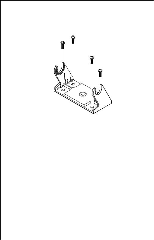
INSTALLATION
MOUNTING
Install the Ultra Classic in any convenient location, provided there is clearance behind the unit when it is tilted for the best viewing angle. Holes in the bracket base allow wood screw or through-bolt mounting. You may need to place a piece of plywood on the back of thin fiberglass panels to secure the mounting hardware. Make certain there is enough room behind the unit to attach the power and transducer cables.
The Classic's gimbal bracket will also accept the GBSA-1 swivel bracket adapter that lets you rotate the unit a full 360°.
The smallest hole that allows one power or transducer connector to pass through is 3/4". After the hole is drilled, push the transducer connector up through the hole first, then drop the power cable down through it.
3
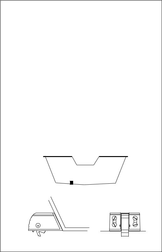
After the cables have been routed, fill the hole with a good marine sealing compound. Offset the bracket to cover the hole. Route the power cable through the slot. Break out one of the holes in the back of the bracket for the transducer cable.
FRONT
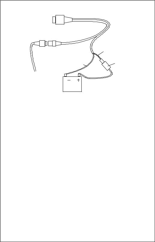
POWER CONNECTIONS
The Ultra Classic works from a twelve-volt battery system. For the best results, attach the power cable directly to the battery. You can attach the power cable to an accessory or power buss, however you may have problems with electrical interference. Therefore, it’s safer to go ahead and attach the power cable directly to the battery. If the cable is not long enough, splice #18 gauge wire onto it. The power cable has two wires, red and black. Red is the positive lead, black is negative or ground. Make certain to attach the in-line fuse holder to the red leadas close to the power source as possible. For example, if you have to extend the power cable to the battery or power buss, attach one end of the fuse holder directly to the battery or power buss. This will protect both the unit and the power cable in the event of a short. Both the Ultra Classic and the Ultra Classic Plus use a 3-amp fuse.
IMPORTANT!
Do not use this product without a 3-amp fuse wired into the power cable! Failure to use a 3-amp fuse will void your warranty.
If you’re installing an Ultra Classic Plus, read the speed/temperature sensor mounting instructions on page 4. Route the sensor’s cable to the Ultra Classic Plus’ power cable and plug it into the connector marked “SPEED/TEMP CABLE”
4
To Ultra
Classic
POWER CONNECTIONS
|
|
RED |
|
|
WIRE |
|
BLACK |
3 amp |
|
WIRE |
FUSE |
TO SPEED/TEMP |
|
|
SENSOR |
|
|
(Not included with |
12 VOLT |
|
Ultra Classic.) |
|
|
BATTERY |
|
|
|
|
TRANSDUCER INSTALLATION
The HS-WSBK supplied with your Ultra Classic is a transom mount transducer. It can be installed on any outboard or stern-drive (inboard\outboard) powered boat. It can also be permanently installed inside the boat to "shoot-through" the hull on some fiberglass boats.
The “kick-up” mounting bracket helps prevent damage if the transducer strikes an object while the boat is moving. If the transducer does “kickup”, the bracket can easily be pushed back in place without tools.
Read the enclosed transducer installation manual carefully before attempting the installation. Determine which of the mounting positions is right for your boat. Use extreme care if mounting the transducer inside the hull, since once it is epoxied into position, the transducer usually can't be removed without damaging it. Remember, the transducer location is the most critical part of a sonar installation. If it isn't done properly, the sonar can't perform to its designed potential.
5
SPEED/TEMPERATURE SENSOR INSTALLATION (Ultra Classic Plus Only)
Mount the speed/temp sensor on the boat’s transom in a location where the flow of water is the smoothest. There should be a minimum of turbulence and air bubbles in the chosen location. The port (left) side of the transom is preferred, however, the starboard (right) side can be used if necessary. Do not mount the speed sensor behind strakes, ribs, or thruhull fittings. These will disturb the flow of water to the speed sensor. In a typical installation, the speed sensor is mounted six to twelve inches from the centerline of the hull. The sensor must always be in the water to function properly. Make certain the chosen location is in the water even at high speed or when the boat is on plane.
Once you determine the proper location, place the sensor on the transom. Make certain the sensor’s bottom is flush with the bottom of the hull. Mark the transom in four places, two in each slot. Drill a 5/32" mounting hole at each location. Mount the sensor to the hull with four #10 stainless steel screws. Use a good grade of caulking compound to seal the screws. Adjust the sensor so it is flush with the bottom of the hull and tighten the screws.
If the base of the transom has a radius, fill the gap between the transom and the sensor with caulking compound. This will help ensure a smooth water flow.
Route the sensor cable to the in-line connector on the Ultra Classic Plus’ power cable. The speed/temp sensor is now ready for use.
GOOD LOCATION 
6
KEYBOARD
The keyboard has keys arranged in two vertical columns beneath the arrow keys. The menu key near the bottom left corner of the keyboard activates the first menu page. The other keys are used to activate the alarm menu, make menu selections, and change modes.
MODE - Pressing this key switches the unit between different sonar modes.
MENU - Press this key to show the menus and gain access to most functions.
ARROW KEYS - These keys are used to make menu selections and to move objects on the screen.
ZOUT, ZIN - These keys let you zoom the screen in and out to see detail.
ALARM - Press this key to activate any of the sonar alarms.
PWR - This key turns the Ultra Classic and it's lights on and off.
ENT, EXIT - These keys let you enter or erase values.
Ultra |
|
Classic |
|
ZOUT |
ZIN |
MODE |
ALARM |
MENU |
EXIT |
ENT |
PWR |
7
OPERATION
POWER/LIGHTS
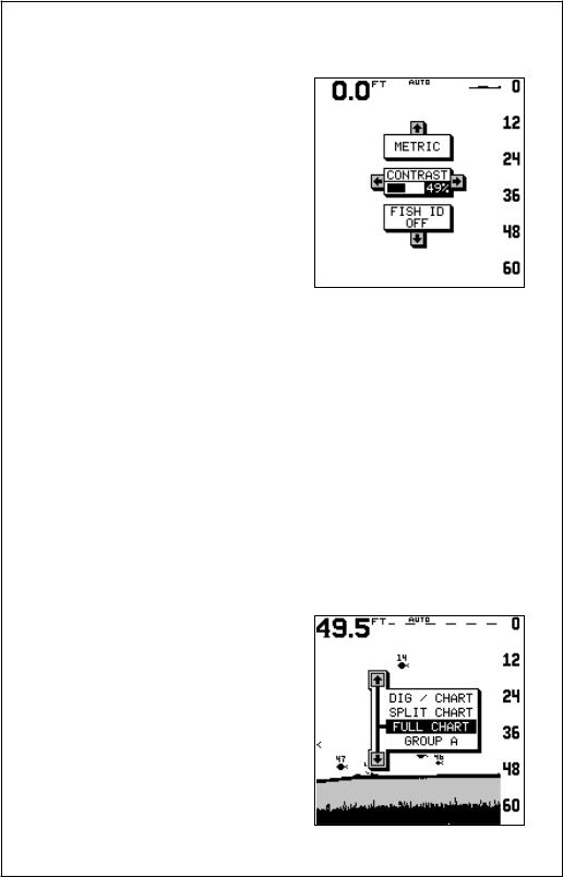
To turn the Ultra Classic on, simply press the PWR key. A screen similar to the one at right appears.
The menus on this screen let you change to the metric mode by pressing the up arrow key, adjust the screen contrast by pressing the left or right arrow keys, or turn Fish ID off by pressing the down arrow key. Press the EXIT key to erase these menus.
The PWR key also controls the lights. Once the Ultra Classic is turned on, press the PWR key to turn the lights on. Press the PWR key again to turn the lights off.
To turn the Ultra Classic off, press and hold the PWR key while a "countdown" appears on the screen. The unit will shut itself off when the countdown reaches zero. Release the PWR key.
MENUS
The Ultra Classic uses menus extensively to guide you through the functions and features of the unit. To use the menus, simply press the MENU key. The options on the menus let you to customize the unit to your particular needs and water conditions. Use the up and down arrow keys to move to different menus. The left and right arrow keys select and adjust menu items. If you ever get lost in a menu, simply press the EXIT key. This clears the menus from the screen.
MODES
The Ultra Classic has four different modes: digital/chart, split-chart, full chart, and window groups. To select a different mode, simply press the MODE key. A screen similar to the one at right appears. Press the up or down arrow key to select the desired mode, then press EXIT key to erase the modes menu. A summary of the modes starts on the next page.
8
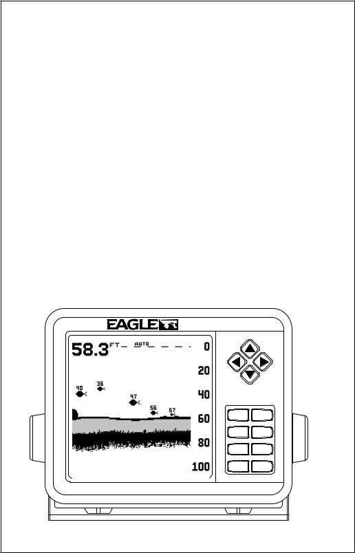
Full Chart
This is the default mode used when the Ultra Classic is first turned on. The bottom signal scrolls across the screen from right to left. Depth scales on the right side of the screen makes it easy to determine the depth of fish, structure, and other objects. The line at the top of the screen represents the surface. The bottom depth shows at the top left corner of the screen. The word "AUTO" at the screen's top center shows that the Ultra Classic is in the
automatic mode, freeing you from sensitivity, range, and noise rejection adjustments.
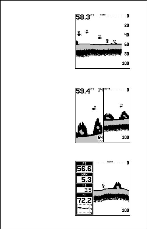
Split Chart
A split chart shows the underwater world from the surface to the bottom on the right side of the screen. The left side shows an enlarged version of the right side. The zoom range shows at the bottom of the screen. In this example, the zoom range is 2X, or two times the right side's view. By pressing the ZOUT and ZIN keys, you can change the left side's zoom from 2X to 4X and back.
Digital/Chart
The digital/chart shows the chart on the right side of the screen. The left side has four digital boxes containing the water depth at the top of the screen, boat speed, distance travelled (log), and surface water temperature. At the bottom of the screen is a temperature graph. (Note: Speed, distance, and temperature displays require a speed/temperature sensor which comes with the Ultra Classic Plus and must be purchased separately for the Ultra Classic.)
9

Window Groups
You can change the displays on the Ultra Classic by using the windows feature. This lets you use different displays for your own fishing or boating situations. This feature gives you 8 different display screens in the window groups alone.
The screens available in the windows mode are divided into two or more windows per screen. Each screen of windows is called a “group”. Group “A” as shown above has the digital depth display in one window, battery voltage in another, water temperature, speed, and distance travelled.
To use the windows feature, first press the MODE key. A screen similar to the one shown at right appears. Highlight the "Group" menu at the bottom of the screen. Now press the left or right arrow keys to sequence through the available groups. When the desired group appears, press the EXIT key to erase the modes menu.
Flasher
The flasher mode changes the Ultra Classic from a graph to a flasher screen. On the screen at right, the water depth is 58.2 feet. A fish is at 50 feet and two other fish show on the dial between 17 and 25 feet. The depth range shows above the digital depth display in the center of the screen. If you have a speed/temperature sensor installed, boat speed, surface water temperature, and distance travelled all show on this screen.
10
AUTOMATIC
When the Ultra Classic is first turned on, the Automatic feature is enabled. This is indicated by the word “AUTO” at the top of the screen. The Automatic feature adjusts the sensitivity and range so the bottom signal is displayed in the lower half of the screen at all times.
To turn Automatic off, first press the MENU key, then press the up or down arrow keys until the "AUTO" menu
appears. Press the left arrow key to switch to the manual mode. The letters “Man” appear at the top of the screen, indicating the unit is in the manual mode. To turn Automatic on, repeat the above steps to get the auto menu, then press the right arrow key.
SENSITIVITY
The sensitivity controls the ability of the unit to pick up echoes. A low sensitivity level excludes much of the bottom information, fish signals, and other target information. High sensitivity levels enables you to see this detail, but it can also clutter the screen
with many undesired signals. Typically, the best sensitivity level shows a good solid bottom signal with Grayline and some surface clutter.
When the Ultra Classic is in the Automatic mode, the sensitivity is automatically adjusted to keep a solid bottom signal displayed, plus a little more. This gives it the capability to show fish and other detail.
However, situations occur where it
becomes necessary to increase or decrease the sensitivity. This typically happens when you wish to see more detail, so an increase in sensitivity is indicated. The procedure to adjust it is the same whether the unit is in the automatic or manual mode.
To adjust the sensitivity, press the MENU key, then press the up or down arrow keys until the "SENS" menu appears as shown above.
11
 Loading...