


Instruction Manual for the eLogger V4
Document Version 1.7,
Model # MPRV4-CONN-100,
MPRV4-LEADS-100, and
MPRV4-LEADS-150
Thank you for your purchase! This instruction manual will guide you through the installation and operation of your eLogger.
Please read the entire manual carefully before proceeding. If, after you read the manual (including the Troubleshooting sections!) you have further questions or problems, please visit our web support page for additional support options, at http://www.eagletreesystems.com/Support/support.ht ml. Note that the latest version of this manual is available in PDF form from the Support page of our website.
Please also fill out the registration form at the end of this manual if you did not purchase your eLogger directly from Eagle Tree Systems, so we can send you important update information.
Intended Uses
The eLogger V4 is intended to be used exclusively for recreational purposes in model planes, boats and cars. Using the eLogger for other purposes is not supported. Further, using the eLogger in situations where its use or failure could result in loss of life, bodily injury or property damage is expressly prohibited. Eagle Tree Systems, LLC, is not responsible for your use of this product, or for any damages or injuries you may cause or sustain as a result of its usage.
Key Features
Here are a few of the features of the eLogger:
∙Logs pack current to +/- 100 amps peak (150 amps peak with MPRV4-LEADS-150) and voltage from about 5 volts to 80 volts
∙Current is measured with a Hall Effects Sensor
∙Adjustable logging rate (from 50 samples per second to one sample every 5 minutes)
∙16 times the logging space of the standard eLogger V3, and lossless data compression. Typically logs all available sensors for about four hours, at 10Hz.
∙All data are logged to permanent memory, which retains the data even when the power is removed
∙Fully compatible with our OSD Pro expander
∙Includes Y cable for throttle position logging
Copyright © 2003-2010 Eagle Tree Systems, LLC
Page 2
∙Great for bench monitoring of battery charging also!
∙Supports the PowerPanel LCD Display
∙Accepts optional inexpensive sensors for three Temperatures, RPM (brushless, magnetic or optical), Airspeed, Altitude, GPS, Servo Current, and more
∙Software computes Wattage, mAH, etc. for complete e-flight data.
∙Fully Compatible with Windows 7 (32 and 64 bit), Vista, 98SE, ME, Win2K and XP™
∙Weighs about 0.8 oz (22 grams). Versions with Wire Leads may weigh slightly more.
∙Comes with our state of the art Windows virtual playback display and graphing software
∙Powerful Graphing software has advanced charting features, such as amps vs. volts
∙Internet Updatable firmware - as we add new features or (heaven forbid) have a firmware bug, the update is just a download away! No need to ship hardware back and forth.
∙Full support for English and Metric units.
∙Software has built in English, German and Chinese languages.
Packing List
Your package should include the following: eLogger (either with integrated connectors or with wire leads), Y cable for throttle logging and battery backup, standard “mini-B” USB c able, and CD-ROM.
Steps to Follow
Installation and use of the eLogger should be quite easy and enjoyable if you follow these few steps:
1.Read through the manual to understand the important warnings, determine what parameters you want to log, etc.
2.Install the eLogger in your model, as described in the eLogger Installation section below. Pay special attention to the polarity and plug-in location of the sensors, since some of the plugs will fit in more than one location!
3.Install and configure the Windows software as described in the Windows installation section below.
4.IMPORTANT: Bench and range test your model as described in the “Using the eLogger” section below.
5.Have fun!
Installation of the eLogger
Connecting the eLogger to Your Model’s Power System
WARNING: High Voltages can cause electric shock. Be extremely careful when working with high voltage packs! Work with high voltages at your own risk.
IMPORTANT: Never let the sensor/USB prongs of the eLogger touch bare battery pack leads, exposed parts of your ESC/BEC, or the motor casing!! Doing so could destroy the eLogger since these items may have high voltage present from your battery pack, and void the warranty.
The below instructions and diagram guide you through the installation of the eLogger.
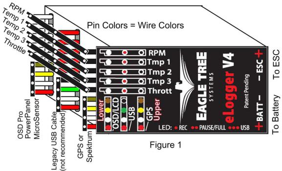
Please refer to Figure 1 below. The eLogger is normally connected so that the connectors or leads marked “Batt” are connected to your battery pack, and the connectors or leads marked “ESC” are connected to your ESC’s power input. The red wires of the “wire lead” version of the eLogger must be connected to t he positive side of the load and source (normally the red wires). For measuring current and voltage during battery charging, it is ok to connect a charger to the ES connection, so that current is flowing “backwards” through the eLogger. The eLogger will still measure current correctly in this mode!
Copyright © 2003-2013 Eagle Tree Systems, LLC
Page 3
IMPORTANT: Do not leave your model’s power system connected to the eLogger when the unit is not in use in the field. Always disconnect the battery from your model when it is in storage.
IMPORTANT: With the Integrated Connector version of the eLogger, always ensure that the wiper prongs of all plugs are not bent or damaged before connecting! A bent or damaged wiper prong could potentially collapse or fold over during connection, and contact the other terminal of the connection, causing a short, or could result in an unreliable connection.
IMPORTANT: When first using your Connector version eLogger, make sure that the mating connectors you are using are making good contact. One way to do this is to gently manipulate the connectors after they are all plugged in, to make sure there are no loose connections.
Connecting Additional Sensors and Accessories to your eLogger
Note: see the instruction manuals accompanying your sensors or accessories for instructions on how to connect and configure them.
Measuring Temperature with the eLogger
Up to three optional temperature sensors can be connected to the eLogger. Eagle Tree offers two types of temperature sensors: the Micro temperature sensor, and the Loop temperatures sensor.
The loop sensor is typically installed by placing the wire loop around the your battery pack, ESC, BEC, or other component, and cinching it in place by pulling the two rubber stays snugly against the surface to be measured. The Micro sensor can be slid under heat shrink, taped on, or otherwise affixed.
Plug the Futaba style connector of each temperature sensor into the eLogger as shown in Figure 1. Note that the plug is polarized by the eLogger’s circuit board.
Note: the Temperature Sensor lead can be easily extended with a standard servo extension cable.
Measuring RPM with the eLogger, Using the Hall RPM Sensor with Magnets
NOTE: see the Brushless RPM Sensor or Optical RPM Sensor instruction manuals if you are using one of those sensors.
Installing the optional Hall RPM sensor and magnets is the most challenging part of installation, but is relatively easy once a good mounting location is determined. Refer to our website’s Flight support page at http://www.eagletreesystems.com for pictures of example installations.
Copyright © 2003-2013 Eagle Tree Systems, LLC
Page 4
To install our magnets, first find a suitable location on your motor or drive train to attach either one or two small
magnets and RPM sensor. Typically, the spinner back plate prop or prop adapter are ideal locations for planes, and a car’s axle shaft is good for car installation. This will of course vary with the construction of the model. Make sure the magnets are mounted on some structure that doesn’t “flop around,” as the m agnets could hit the sensor in this case. The RPM sensor must be mounted so that it does not move around, and is within 1-2 mm of the two magnets as they spin. On typical plane installations, there’s usually a place where the back of the sensor can be glued to a flat surface near the spinning magnets. The
RPM sensor kit includes four magnets, providing you with up to 3 spares.
Installing Magnets
Once you have determined where to install the magnets, decide whether you will drill a hole so that the magnets will mount flush with the surface, or if you will just glue the magnets to the surface. Though somewhat more difficult and permanent, mounting the magnet flush with the surface is the best long term approach, since the mounting will be much more rugged, and the risk of imbalance due to not mounting the magnets exactly 180 degrees apart is reduced. In fact, if the magnet is mounted flush in another metal material, it is quite possible that no shaft imbalance will occur if you only mount one of the magnets total.
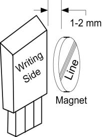
To flush mount the magnets, drill a hole just slightly larger than the diameter of the magnet size you choose, and of the same depth as that magnet. If you decide to surface mount the magnets, thoroughly clean this area and lightly scuff it to improve adhesion. Glue the magnets with the side marked with a red line facing inward (hidden), using epoxy, or other strong, suitable glue. It’s important that the red line on the magnets faces away from the sensor once the sensor is installed. When using two magnets, the magnets should be glued 180 degrees apart to keep the shaft in balance.
WARNING: make sure that the magnets are glued sufficiently so that they will not detach and create a hazard, and always wear safety glasses when your motor is running! It is also a good idea to put a piece of heatshrink tubing or electrical tape around the magnets, to further secure them.
Installing the Magnetic RPM Sensor
Once the magnets are glued and the glue is completely dry, temporarily position the RPM sensor so that the side of the sensor with printing (or a colored dot) is facing the side of the magnets WITHOUT the red line. The sensor now needs to be glued so that it is held rigidly into position. Before gluing, put a small spacer (1-2 mm thick) between the sensor and one of the magnets to ensure proper spacing.
If desired, a small piece of brass tubing can be glued or heatshrunk to the back of the sensor to ease mounting and increase stability.
After the sensor is glued and the glue is completely dry, remove the small spacer and rotate the drive train or propeller to ensure complete freedom of movement. Also make sure that the sensor won’t vibrate and come in contact with the magnets during operation. If this happens, the sensor will be destroyed, and the eLogger could be damaged.
Once these steps are complete, plug the Futaba style connector on the sensor into the eLogger as shown in figure 1. Note that a standard Futaba style servo extension cable can be used to lengthen the RPM sensor wire if needed.
Using Existing Magnets
Note: if your motor already has magnets mounted for some other purpose, there’s a good chance you can use them. Take one of the magnets included with the RPM sensor kit, and put that magnet up against the previously mounted magnet. If the red line of the eLogger magnet faces down so that the sensor can be mounted facing the side of the magnet with no red line, mount the sensor with the printed side toward the magnet. If the side of the magnet with the red line is visible when on top of the previous magnet, the polarity is reversed. This should work correctly if you install our sensor backwards (printed side of sensor away from magnets).
Using Existing RPM Sensors
Copyright © 2003-2013 Eagle Tree Systems, LLC
Page 5
Several of our customers have been able to use existing RPM sensors, such as governors or turbine sensors, with our products. The following steps must be followed:
1)Determine the “pinout” of the existing sensor. Compatible sensors will have Power, Ground, and Signal connections. The eLogger’s RPM pinout, from left to right, is: Power (black wire), Ground (red wire), Signal (white wire).
2)Obtain a “Y” cable to connect your existing sensor to its connection, and also to the eLogger’s RPM connection. NOTE: Power for the sensor should come only from the connection the sensor is normally plugged into. So, only Gound and Signal wires should be routed from the existing sensor to the eLogger. The power wire of the Y cable between the sensor and the eLogger should be cut before connecting it to the eLogger. This is necessary to avoid connecting the power of the existing sensor connection to the eLogger’s power connection.
3)Thoroughly test the system to make sure the sensor still works with whatever it was originally connected to, after Y’ing to the eLogger.
Configuring the RPM Sensor
In the software, click “Calibration, Calibrate Moto r RPM” to indicate to the software the type of sens or you have installed, and to enter the gear ratio and the number of magnets.
Monitoring your Model’s Throttle Position with the eLogger
IMPORTANT: Do not use the throttle Y cable if your receiver is powered with greater than 6 Volts! Make sure you connect the battery pack to the eLogger only AFTER connecting the throttle Y cable and all other connections to the eLogger.
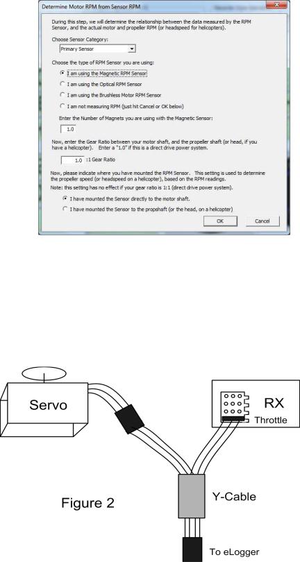
The eLogger logs servo positions by measuring the pulses coming from your receiver to the throttle servo, via the included Y cable. The Y Cable has 3 connections. The “Futaba” male plug (at the “base of the Y”) connects to the eLogger as shown in Figure. The universal male and female plugs of the Y cable connect to your receiver’s throttle channel, and to your throttle servo, respectively. See Figure 2 for connections of the Y cable to your Receiver and Servo.
Additionally, when the Y Cable is connected, the Y cable serves to provide secondary (backup) power to the eLogger, which is required with certain combinations of higher pack voltages and accessories.
Note that when the Y cable is connected to your receiver, there is a common ground connection produced between your receiver and your battery pack, which is also connected to the eLogger. This will bypass any optical or other isolation that might be built into the ground connections of your ESC. We are aware of no issues with connecting a wire between battery ground and receiver ground in these cases, but proceed with caution (at your own risk) as there is the unlikely possibility that your hardware may be damaged by such a connection, and make sure you do an antenna down range check after making this change.
Copyright © 2003-2013 Eagle Tree Systems, LLC
Page 6
Installing and Using the Windows™ Software
The eLogger V4 is configured, and data is downloaded, using our powerful Windows software. Please read the information below on installation, configuration, and data download.
Installing the Windows Software
The supplied Windows software is compatible with USB equipped PCs running Windows 7, Vista, XP, Windows 98SE, Millennium, or Win 2K. The software is NOT compatible with Windows 98 Original Edition (Gold), or NT 4, even if the PC has USB support.
NOTE: the software included on CD with the unit was current at the time of manufacture. Please check our eLogger Support page at http://www.eagletreesystems.com to see if there is a newer version of the Windows software which may have addressed issues you could encounter. Also, at any time after software installation, just click “Help, Download latest up dates…” to check to see if a newer version of our software is available.
To install the software, just place the CD in the CD-ROM drive. If AutoPlay is enabled on your PC, the setup program should run automatically. If it does not run, click on My Computer, click on the icon for your CD-ROM drive, and click on the “setup.exe” software icon in the drive window.
Follow the Setup Wizard to install the eLogger software. Once installation is complete, the eLogger may be launched either from its Desktop Icon, or by choosing the eLogger software from the Start->Programs->Eagle Tree Systems folder.
Connecting the eLogger to USB
A standard “mini” USB cable is included, which conn ects to the eLogger’s USB port.
Updating the eLogger’s Firmware
Each time a new version of our software is installed, the software will check the firmware version of the eLogger, and will prompt you to update the firmware if a new version is available (as shown in the “Firmware Control” figure below) . Always update the firmware if prompted to do so. When new firmware is available, the “Firmware Control” screen will appear. Si mply click the “Click Here to Update Recorder Firmware Version” to start the firm ware update process.
Copyright © 2003-2013 Eagle Tree Systems, LLC
 Loading...