


Guardian 2D/3D Stabilizer
Document Version 2.3 |
|
PC Software 10.69 or later |
Assembled in Taiwan |
Introduction
Thank you for your purchase! Based on Eagle Tree's proven inertial stabilization technology, the Guardian 2D/3D Stabilizer (the Guardian) stabilizes most types of fixed wing models, and works with most any radio. Unlike most “gyro stabilizer” products on the market, when configured correctly the Guardian provides true wing leveling stabilization as well as precise fly-by-wire control. This lets you configure the Guardian to return to level flight in an emergency, by just flipping a radio switch!
Read the Manual!
This manual contains important instructions related to safety. Read the entire manual before proceeding, to become familiar with the features and operation of the Guardian. Failure to correctly configure or operate the Guardian could cause damage to personal property or serious injury! The latest version of this manual is available in the Product Manuals section of the Support tab on http://www.eagletreesystems.com. The online manual is in full color, and includes any updates that were made after this manual was printed. If, after you read the manual, you have further questions or problems, see the “How to Get
Help” section below.
Packing List |
Introduction 1 |
||
|
|
||
|
Input Voltage Range: 4.5v to 16v |
Terms and Symbols 1 |
|
|
|||
|
Current Draw: Approximately 31mA |
General Safety Precautions 2 |
|
|
Dimensions: 41mm x 22mm x 11mm (1.62 inches x 0.86 inches x 0.42 inches) |
Main Features 2 |
|
|
Mass: 11 grams (0.4 ounces) including harness |
||
|
|||
|
Maximum Servo Current through Guardian: 5 Amps |
Overview/Quick Start 2 |
|
|
Recommended Airframes: the Guardian is not recommended for large or heavy airframes, due to no or limited |
Guardian Physical Connections/ Controls 3 |
|
|
testing on these types of models at this time. |
||
|
|
||
|
|
The Receiver Connection Harness 4 |
|
How to Get Help |
Configuring the Mode and Gain Channels 4 |
||
Eagle Tree is committed to providing great customer service. If you’ve read the manual and something is not clear, just |
|||
|
|||
ask. We’d much prefer to take the time to answer your questions, rather than having you waste your valuable time |
Receiver Requirements 5 |
||
struggling with an issue. |
Mounting the Guardian in your Model 6 |
||
To get help, visit the Eagle Tree Guardian support thread at |
|||
|
|||
http://www.rcgroups.com/forums/showthread.php?t=1596644. Chances are someone has posted a solution to your |
Preflight Checks 6 |
||
problem already. If not, posting your problem there will get a very quick response from the Eagle Tree community. |
First Flight 6 |
||
|
|
||
If you prefer to not post on the forum, or you feel there is a problem with your Eagle Tree hardware, please open a |
|
||
support ticket with us at http://ticket.eagletreesystems.com and we will respond to your support ticket as soon as we can. |
Tuning Stabilization Gains 7 |
||
Note that when you create a support ticket, you will be emailed a link that will let you check the status of the ticket. If |
Status LED 8 |
||
you do not receive the email, this most likely means that a spam filter is intercepting emails from Eagle Tree. |
|||
|
|||
Also Eagle Tree greatly values your feedback on how we can improve our products. To leave us feedback for a new |
Mode/Config Switch Behavior 9 |
||
feature request or improvement, either post the feedback on our support thread above, create a support ticket with your |
The Guardian PC Software 11 |
||
feedback, or just email us at support@eagletreesystems.com. |
|||
|
|||
Terms and Symbols used in the Manual |
Guardian Configuration Page Software |
||
Reference 12 |
|||
Your package should include the following: The Guardian, the receiver connection harness with labeled connectors, the |
Specifications (approximate) 1 |
||
quick reference card, and a printed version of this manual. |
|
||
|
|
How to Get Help 1 |
|
Specifications (approximate) |
|
||
Warning that could affect safety or result in injury, a crash, property damage or Guardian hardware damage if not heeded.
Helpful Note
Pitch – Lift or descent of the nose and tail of the model. Normally controlled by the elevator, or movement of elevons in same direction.
Roll – Rocking movement of the wings, side to side. Normally controlled by ailerons, or movement of elevons in opposite directions.
Yaw – Turning of the airplane without banking. Normally controlled by the rudder.
Axis – an imaginary line drawn horizontally through your model’s wing (for Pitch), horizontally through your fuselage (for roll), or vertically through the center of your fuselage (for yaw).
Control Stick – The stick on your radio that controls elevator and aileron functions (pitch and roll). Attitude – The orientation of the model with respect to the horizon.
2D Mode – A mode where the model is brought to a level attitude (level flight and level wings) by the Guardian when the control stick is centered.
3D Mode – A mode where the Guardian attempts to hold the model’s present attitude when the Control Stick is centered, by moving the model’s control surfaces automatically.
Heading – The present direction of travel of the model with respect to North.
Control Surfaces – Your model’s elevator, ailerons (or elevons) and rudder (if equipped).
Copyright 2013-2014 Eagle Tree Systems, LLC Page 1

Receiver Connection Harness – The cable included with your Guardian that lets you connect your Guardian to your receiver’s outputs.
Mode/Config Switch – A two or three position switch on your radio transmitter which you have configured to control the “Mod” input on the Guardian’s Receiver
Connection Harness.
Toggle – One fairly rapid movement the Mode/Config Switch between its extents. (UP/DOWN or DOWN/UP)
Configuration Gestures – A series of toggles of the Mode Config/Switch. The number of times you toggle the switch determines which configuration step is performed.
Gain Knob – A knob or switch on your radio transmitter which you have configured to control the “Gain” input on the Guardian’s Receiver Connection Harness.
 General Safety Precautions
In addition to other warnings and other precautions in this manual, the following should always be observed:
1)The Guardian is intended for recreational use only! Any other use is not supported.
2)Fly safely! Please refer to the American Model Association’s Safety Code at http://www.modelaircraft.org/files/105.PDF, or the appropriate safety code for your country. Always obey the law when flying.
3)If you have never set up or operated an RC model before, you will need help from an experienced modeler. Local RC clubs are great ways to meet experienced modelers, and receive the required training.
4)Never operate your model aircraft near or over buildings, power/telephone lines, or other obstacles. Never operate your model aircraft near or over yourself or other people!
5)RC models and accessories are not toys, and should be kept away from children, without proper adult supervision.
6)Be sure to always fly conservatively and exercise common sense!
Main Features
The Guardian 2D/3D Stabilizer has two main modes of operation: 2D Mode and 3D Mode. While in flight, a spare switch on your radio lets you switch between 2D mode, 3D aerobatic mode, and no stabilization. Imagine performing a difficult 3D maneuver with ease, then just flipping a switch to instantly return to level flight!
Please see the Tuning Stabilization Gains section for notes on preventing damage from re-leveling too quickly.
2D Mode
When set for 2D Mode, the Guardian provides much smoother flight and wing leveling stabilization for your model, which makes it a lot easier to adjust and fly your plane. In this mode, the Guardian "remembers" level flight for your model and returns it to level flight when needed. In 2D mode, flying in moderate wind can seem just as easy as flying in no wind at all!
Additionally, the Guardian provides precise "fly by wire" control, in which it interprets your control stick deflections as command angles for Pitch and Roll. For example, pushing and holding your control stick left will cause your model to enter a level altitude banked left turn. This mode is ideal for beginners as well as experts looking for a reduced workload on take-off and landing. It also can be useful for aerobatic pilots seeking to recover quickly after losing orientation.
The Guardian also includes an advanced “Oscillation Suppression” feature that can quickly detect and eliminate oscillations stemming from too high gains.
2D Heading Hold Submode
With 2D Heading Hold submode, the Guardian will assert Aileron deflections to keep your model locked on its current 2D heading. Whenever the control stick is moved to turn, this heading is reset and subsequently relocked as soon as the stick is centered again.
Automatic Turn Coordination
When enabled, Automatic Turn Coordination will cause the Guardian to employ the “step on the ball” method of actuating your Rudder for you. As you enter a banked turn, the Guardian will assert a coordinating response on the Rudder automatically. This deflection is completely based on the side-to-side g-force measured by the Guardian and does not introduce any movement on the Ailerons. This mode is great for models that skid easily.
 Expected behavior here is that on the bench, the Guardian will introduce a Rudder movement that will yaw the model towards the direction it is being rolled. For instance, if a stationary plane is rolled to the right, the Rudder should assert a right yaw moment to follow the detected turn.
 Since this is based on horizontal g-force, the Guardian may exhibit different behavior in the air in a “skid” condition where the model is moving one direction, but pointing another. The Automatic Turn Coordination will work to point the model in the direction that it is moving through the air in this case.
3D Mode
In 3D Mode, the Guardian works to smooth out turbulence and stall characteristics to bring stability and precision to your model while leaving the feel of flying the same as without stabilization. This mode is intended for more advanced pilots looking for improved stability without compromising on performance and feel.
3D Heading Hold Submode
Centering the control stick in 3D Mode will engage 3D Heading Lock, which will cause your airplane to hold its present flight orientation (assuming it is aerodynamically able to do so). In this mode, when the control stick is centered the Guardian remembers its current Pitch, Roll and Heading and works to keep those locked. Moving the control stick immediately resets the locked heading, allowing for instantaneous transitions from locked maneuvers to dynamic flight. Actuation of the Rudder control will reset just the Yaw axis, without affecting the lock on Pitch and Roll.
Direct Rate 3D Control Submode
Unlike many other gyro stabilization systems, the Guardian employs Direct Rate 3D Control to translate your stick deflections to angular rates without forcing you to “fight the gyro.” With this feature enabled, the Guardian interprets your stick deflections as commanded angular rates and attempts to have your model follow those commands. This way, snap rolls and other high speed maneuvers are possible without compromising on stabilization effects.
Overview/Quick Start
First, read through the manual to get a “big picture” understanding of mounting, connection, configuration and operation of the Guardian. Consider watching the Guardian tutorial video located at http://youtu.be/Rt8Y3Lxnv-0.
While the Guardian has a wealth of configurable features and options, getting in the air for most airframes requires minimal setup and configuration. At a minimum, the Guardian should be connected between your receiver and your servos and then told some basic orientation and trim details of your model. These steps are detailed as follows. Note: it is assumed here that you have a transmitter switch connected to the Guardian’s Mode/Config input.
Connect the Guardian to your receiver using the included servo wire harness. Refer to the Receiver Connection Harness section for more information.
Connect your servos to the matching servo output channels on the Guardian. Note that the servo connectors’ signal wires should be on top when the Guardian’s label is facing the sky. See the Wing Type Configuration section for details on specific airframes.
Copyright 2013-2014 Eagle Tree Systems, LLC |
Page 2 |
To reduce the possibility of extreme servo deflection, it is recommended that you disable stabilization during initial setup. There are 3 ways to disable stabilization:
o If you are using a 3 position Mode/Config switch, move it to the center (disabled) position.
The Guardian’s LED should be OFF when in the Mode/Config switch is in the disabled position.
oIf you are controlling overall Guardian gain with a knob on your transmitter, set your Gain dial to -100% servo deflection (~1.1ms pulse length) to disable stabilization.
oIf neither of these methods is applicable, turn the Pitch/Roll/Yaw dials on the Guardian to their centered position, which will also disable stabilization.
Configure your Guardian and transmitter for your wing type (see the Wing Type Configuration section for more information):
oTurn off Elevon and V-Tail mixing in your transmitter, if it is enabled. Elevon and V-Tail mixing will be done by the Guardian.
oBy default, the Guardian is programmed for traditional wing types (mixing disabled). If your model requires elevon or V-Tail mixing, you can quickly enable this feature by doing the following:
Within 15 seconds of powering on, toggle your Mode/Config switch three times, which is the Toggle Elevon Mixing switch gesture (move the switch up-down-up-down-up-down if the switch is presently down, or down-up-down-up-down-up if the switch is presently up).
Your servos should “twitch” three times to indicate that you have toggled elevon mixing ON/OFF.
Move your control sticks to ensure that the mixing is now enabled. If not, you may need to re-run the Enable Elevon Mixing step.
Configuring the wing type correctly is critical! The model will not be controllable in the air if the wing type is incorrect.
Place your plane on a test bench so its orientation is the same as it would be during straight and level flight.
Reset your Trims and Level Flight Orientation:
oWithin 15 seconds of powering on, and with your plane still in the orientation of level flight, toggle your Mode/Config switch once, which is the Reset Level Flight and Trims switch gesture. Your servos should “twitch” once to indicate that you have reset your controller trims and level flight orientation.
Any time you re-trim your plane or re-mount the Guardian, you will need to do this again to ensure best stabilization performance.
Compensate for servo directions and throws:
o Set your Mode/Config switch to -100% (switch position 2 on a SpektrumTM controller). This activates “2D Mode”. The Guardian’s LED should be blinking on and off repeatedly, which indicates 2D Mode.
oTurn up the Overall Gain knob on your transmitter its center position (100% overall stabilization gain) if you are using the gain knob.
oObserve how your servos react as you pitch, roll and yaw your plane.
oAdjust the Guardian Pitch, Roll and Yaw axis dials with a screwdriver, so the servo for each axis deflects in the correct direction to bring your model back to level. A centered dial asserts zero stabilization on that axis. Turning it clockwise or counterclockwise increases the gain and selects the servo stabilization direction. See Figure 6 to see which directions your surfaces should move as you move your model.
Ensure your Transmitter’s elevator and aileron endpoints are set for +/-100%, if applicable. The Guardian expects full ranges when it interprets your command stick deflections to determine the desired orientation in 2D Mode.
Preflight:
oCheck that when you pitch, roll and yaw your plane while in either 2D or 3D Mode, that your servos oppose your movements. See Figure 6 in the Preflight Checks section for more information.
If the control surfaces are not correctly set up to move in the appropriate directions to counteract pitch, roll and yaw movements, it could result in a crash!
o Do an engine run-up and confirm that the control surfaces are not moving around randomly due to excessive vibration or a loosely mounted Guardian.
If the control surfaces are moving on their own during run-up, this could result in a crash! Do not fly if this is the case.
o Range check your model!
Guardian Physical Connections/ Controls
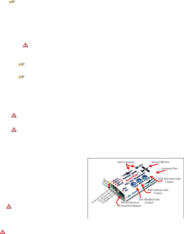
Please refer to Figure 1. The Guardian has the following physical connections and controls:
Port for Receiver Connection Harness – this is where the included harness connects. The servo plugs on the harness then connect to the appropriate receiver channels. Please see the Receiver Connection Harness section below for more
information.
Servo Connection Ports – connect the appropriate servos to the Guardian here, noting the plug orientation in Figure 1. Please see the Wing Hookup Configurations section below for more information.
Yaw, Roll and Pitch gain control dials – these dials set the individual gains for the Yaw (Rudder), Roll (Aileron) and Pitch (Elevator) axes, as well as setting the direction of stabilizing servo travel, and are adjusted with a small screwdriver. Please see the Tuning Stabilization Gains section for more information.
Micro USB port – this port accepts a “Micro B” USB cable (not included). Connection to a PC lets you update the Guardian firmware, and also configure and tune your Guardian via your PC. Please see the PC User Interface section for more information.
|
Do not apply upward force on the USB connector when a |
|
|
cable is inserted! Doing so can damage it. |
|
|
Accessory (Data) Port – this port is for future expansion, and is not used |
Figure 1 – Guardian Connections and Controls |
|
presently. Please let us know how we should use this port! |
|
|
|
LED Viewports – for your convenience, the status LED can be seen from both the top and side of the Guardian case. Please see the Status LED section for more information.
Servo compatibility notice: Eagle Tree has received reports that some instances of the E-Flite™ model EFLR7155 servo do not work correctly with the Guardian (and some similar devices) due to higher than normal loads placed on the servo signal line, while other instances of this servo model do not exhibit this behavior.
Symptoms can include sudden, uncommanded servo movements. Therefore, we cannot recommend using this model servo with the Guardian.
Copyright 2013-2014 Eagle Tree Systems, LLC |
Page 3 |
The Receiver Connection Harness
Receiver Connection Harness Pinout
The lightweight receiver connection harness with labeled connectors should make it easy for you to hook up the Guardian to your receiver.
A diagram of the harness is shown in Figure 2, for your reference. It has the following labeled receiver connections:
Ail – (required) Connects to your receiver’s Aileron output channel. Note that this channel also supplies power and ground to the Guardian and the servos connected to the Guardian.
Elv – (required) Connects to your receiver’s Elevator output channel
Rud – (optional) Connects to your receiver’s Rudder output channel
Aux - (optional) Connects to your receiver’s Second Aileron or Flaperon output channel, if needed
Mod – (optional, recommended) The Mode/Config input connects to either a two-position or threeposition switch. It allows you to switch the Guardian mode during flight and to do radio stick configuration of the Guardian. See the Mode/Config Switch Behavior section for more information.
Gain – (optional) The Gain input connects to a knob (or slider) on your receiver, and lets you adjust the overall stabilizer gain during flight. See the Stabilization “Master Gain” Control section for more information.
Receiver Connection Harness Load Capacity
When connected typically, the Aileron lead of the Guardian’s receiver connection harness takes power from your receiver, and this powers the servos you have connected to the Guardian. The Receiver Connection Harness is easily capable of handling the power requirements of typical analog and digital servos.
However, if the servos you have connected to the Guardian are very large, and/or have a combined current draw of greater than 5 amps, an additional power cable is required. Note that if your BEC or receiver battery is rated at 5 amps or less (the vast majority are), a backup cable should not be needed. Note
also that the Aileron lead of the harness should not be excessively warm after flying, which could indicate that backup power is needed.
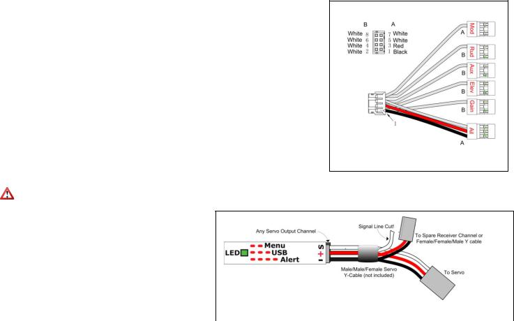
If the servos you have connected to the Guardian draw greater than 5 amps all together, there are two ways to supply additional power to your servos, which will provide additional current carrying capability to the servos you have connected to the Guardian:
1) |
If you are not using all the servo output connections on your |
|
|
|
Guardian, a male to male servo wire (with the signal line cut!) |
|
|
|
can be connected between a free servo channel on the |
|
|
|
Guardian, and a free channel on your receiver. |
Figure 3 – Providing Backup Power when all Guardian Servo Channels Used |
|
2) |
If all the servo connections on the Guardian are being used, a |
||
|
|||
|
male/male/female Y cable (ET p/n CAB-Y-1 or similar) with |
|
|
|
the signal line cut can be used to provide additional power to the servos, as shown in Figure 3. |
||
Configuring the Mode and Gain Channels
For best results, we recommend that the Mode/Config input wire (labeled Mod) on the receiver connection harness be connected to a channel on your receiver that is controlled by a 2 or 3 position switch. If you have problems getting this to work, you can test the switch temporarily by connecting a servo to the channel on your receiver that is controlled by it. Then, move the switch. If it has 2 positions, you should see the servo move from one extent to the other. If it has 3 positions, you should see the servo move from one extent, to center, and to the other extent.
Once you confirm this, reconnect your Mod wire to that channel. If using a 2 position switch, the Guardian will then be able to be switched between 2D and 3D Mode. If using a 3 position switch, the Guardian will be able to be switched between 2D, off, and 3D. If you want to use the Guardian with a 2 position for 2D and off, you will need to reduce one endpoint for that channel (if your transmitter is capable of adjusting endpoints) so that in one position the Guardian's LED blinks, and in the other position it stays off.
If you have an additional free channel that can be controlled by a slider or knob, you can use this channel to remotely change the Overall Gain on the Guardian, by connecting that channel to the Gain wire on the receiver connection harness. In order to test this slider or knob, temporarily connect a servo to the channel on your receiver that is controlled by the knob/slider. Then, move the knob/slider. You should see the servo move from one extent to the other as you operate the knob/slider.
Performing Reset Level Flight and Trims
Assuming you are using a Mode switch, you will want to power the system on with the switch in the 2D or 3D Mode position. Then, within 15 seconds of powering on the system, move the switch to the opposite position and back to the original position quickly. The control surfaces will twitch once to indicate level flight and trims has been set.
 The meaning of each switch position can be custom defined through the PC software. See The Mode Config Tab in the The Guardian Configuration Page Software Reference section of this manual, for more information.
If you need more detailed information about programming your specific radio, it is suggested to refer to your radios operating manual. Otherwise, you may want to check the Guardian thread on rcgroups.com to see if someone else is using the same setup you are. The thread is located here; http://www.rcgroups.com/forums/showthread.php?t=1596644
Performing Reset Level Flight in the Air
Sometimes, the most accurate way to record level flight is when your model is in the air, flying straight and level. Fifteen seconds after initial power-on, the Guardian will enable a 5-toggle gesture that will record the current pitch and roll before storing it as the new level flight orientation.
The recommended method to best utilize this feature is to enable 2D Heading Hold. Given a little time to settle out, the 2D Heading Hold should make the model fly very straight, allowing you to focus on just controlling altitude with the Elevator stick. Once the model is flying straight and level, perform the 5-toggle gesture. Upon completion, the orientation that the model was in at the beginning of the toggle gesture will be used as the new level flight orientation.
Copyright 2013-2014 Eagle Tree Systems, LLC |
Page 4 |

 The current pitch and roll are recorded every time the Mode switch is transitioned out of a 2D-Mode position at the beginning of a toggle gesture. Once the 5-toggle gesture is completed, those recorded pitch and roll values are stored to permanent memory as the new level flight orientation. If the 5-toggle gesture does not complete within the standard time-out (1 second per toggle), then the recorded orientation information is discarded and no changes are made.
Receiver Requirements
Receiver Connection Requirements
The number of connections between the Guardian and your receiver depends on type and capabilities of your model, the level of Guardian in-flight control you require, and the number of spare receiver channels you have. For very basic models, the Guardian is capable of operating with only the Elevator input and Aileron input connected.
BEC/Receiver Battery Power Requirements
The Guardian 2D/3D Stabilizer is sensitive to deep voltage drops, which means that your BEC or receiver battery must be sufficient to maintain a voltage of at least
3.5 volts, even under full servo load. The Guardian will shut off if the voltage drops below this level! Under normal conditions, the BEC voltage should be at least 4.5 volts to achieve the best stabilization performance. Never exceed 16V!
If the voltage drops below 3.5 volts for a short period of time, the Guardian will experience a “brownout.” In this case, the Guardian will attempt to recover gracefully. During recovery, stabilization may be disabled or suffer from performance issues while it does so.
If you experience issues like this in flight, bring the Mode/Config Switch to either 3D Mode or Stabilization Disabled Mode (if your transmitter is configured for mode control) and land immediately.
 If a brownout condition is detected by the Guardian, the LED will blink an error code of four long blinks followed by one short blink. If this LED signal is ever seen after a flight, it is recommended that the BEC or battery be upgraded. Please see the Status LED section for more information on how to interpret LED blinks.
Failsafe position of Receiver Inputs
 If, after you reset level flight and trims, an input channel should become disconnected from your receiver during flight, it will cause the Guardian to use the stored trim setting for that servo channel input as a failsafe.
Functionality Limitations without the Mode and Gain Inputs or the PC Connection
While the Guardian is capable of flying without the Mode or Gain inputs being connected, most configuration steps need either the Mode input or a PC connection in order to be done correctly. The Guardian comes preconfigured for standard fixed wing flight. Configuring the Guardian any other way will need to be set up using either the Radio Stick Menu, which is activated using the Mode switch, or the PC Software, which requires a USB connection. Either the Mode Input or a PC is needed to Reset Level Flight and Trims as well.
In the case where neither of these is available, it is recommended that you remap an unused channel, such as Throttle or Rudder to the Mode Input temporarily to emulate a Mode Switch. Next, ensuring that your controller’s servo ranges for that channel are set to 100%, the remapped channel can be used to enter the Radio Stick Menu.
While the Radio Stick Menu will allow most configurations, it is only possible to access some features through the PC Software. These include the AHI display, saving and reloading past configurations and the ability to limit your Servo Deflections (available under the Servo Config tab).
Wing Type Configuration
The Guardian is configurable for most common wing types. By default, it is configured for traditional wing control. Please refer to Figure 4, which shows the receiver and servo connections for typical wing types.
|
|
Traditional Models with Single Aileron Servo |
|
Traditional Models with Dual Aileron/ Flaperon servos (with |
|||||
|
|
|
|||||||
|
|
|
Model Control Type setting: Standard (this is the default) |
|
Transmitter mixing) |
||||
|
|
|
Guardian Receiver Inputs |
|
|
Model Control Type setting: Standard (this is the default) |
|||
|
|
|
o |
Receiver Aileron Output → Guardian Aileron In |
|
||||
|
|
|
|
|
Guardian Receiver Inputs |
||||
|
|
|
o |
Receiver Elevator Output → Guardian Elevator In |
|
||||
|
|
|
|
|
o |
Receiver Aileron Output → Guardian Aileron In |
|||
|
|
|
o |
Receiver Rudder Output → Guardian Rudder In |
|
|
|||
|
|
|
|
|
o |
Receiver Elevator Output → Guardian Elevator In |
|||
|
|
|
o |
Guardian Aux-In is not connected |
|
|
|||
|
|
|
|
|
o |
Receiver Rudder Output → Guardian Rudder In |
|||
|
|
|
Guardian Servo Outputs |
|
|
||||
|
|
|
|
o |
Receiver Second Aileron or Flaperon Output → Guardian |
||||
|
|
|
o |
Guardian Aileron Out → Aileron Servo (if no Aileron |
|
|
|||
|
|
|
|
|
|
Aux In |
|||
|
|
|
|
present, connect Rudder Servo to Aileron Out) |
|
|
|
||
|
|
|
|
|
|
Guardian Servo Outputs |
|||
|
|
|
o |
Guardian Elevator Out → Elevator Servo |
|
||||
|
|
|
|
|
o |
Guardian Aileron Out → Aileron Servo |
|||
|
|
|
o |
Guardian Rudder Out → Rudder Servo |
|
|
|||
|
|
|
|
|
o |
Guardian Elevator Out → Elevator Servo |
|||
|
|
|
o |
Guardian Aux Out is not connected |
|
|
|||
|
|
|
|
|
o |
Guardian Rudder Out → Rudder Servo |
|||
|
|
|
|
|
|
|
|||
|
|
|
|
|
|
|
o |
Guardian Aux Out → Second Aileron or Flaperon Servo |
|
|
|
|
|
|
|
||||
|
|
V-Tail with Ailerons |
|
Elevon / V-Tail with no Ailerons |
|||||
|
|
|
Model Control Type setting: V-Tail |
|
|
Model Control Type setting: Elevon |
|||
|
|
|
Guardian Receiver Inputs |
|
|
Guardian Receiver Inputs |
|||
|
|
|
o |
Receiver Aileron Output → Guardian Aileron In |
|
|
o |
Receiver Aileron Output → Guardian Aileron In |
|
|
|
|
o |
Receiver Elevator Output → Guardian Elevator In |
|
|
o |
Receiver Elevator Output → Guardian Elevator In |
|
|
|
|
o |
Receiver Rudder Output → Guardian Rudder In |
|
|
o |
Receiver Rudder Output → Guardian Rudder In |
|
|
|
|
o |
Receiver Second Aileron Output → Guardian Aux In |
|
|
o |
Guardian Aux-In is not connected |
|
|
|
|
|
(optional) |
|
|
Output |
|
|
|
|
|
Output |
|
|
|
o |
Guardian Aileron Out → Elevon Servo 1 |
|
|
|
|
o |
Guardian Aileron Out → Aileron Servo |
|
|
o |
Guardian Elevator Out → Elevon Servo 2 |
|
|
|
|
o |
Guardian Elevator Out → V-Tail Servo 1 |
|
|
o |
Guardian Rudder Out → Rudder Servo |
|
|
|
|
o |
Guardian Rudder Out → V-Tail Servo 2 |
|
|
o |
Guardian Aux Out is not connected |
|
|
|
|
o |
Guardian Aux Out → Second Aileron Servo (optional) |
|
|
|
|
|
|
|
|
|
|
|
|
|
||
|
|
|
|
Figure 4: Receiver and Servo Connections for Typical Wing Types |
|||||
|
|
|
|
|
|
|
|||
Copyright 2013-2014 Eagle Tree Systems, LLC |
|
|
Page 5 |
||||||
 Loading...