


MagnaView Plus
1
MagnaVMagnaV
MagnaVMagnaV
MagnaV
iewiew
iewiew
iew
andand
andand
and
MagnaVMagnaV
MagnaVMagnaV
MagnaV
iew Plusiew Plus
iew Plusiew Plus
iew Plus
INSTALLATION AND OPERATION
INSTRUCTIONS
TM
MagnaViewMagnaView
MagnaViewMagnaView
MagnaView

2
Eagle Electronics
PO Box 669
Catoosa, OK 74015
TABLE OF CONTENTS
INTRODUCTION ............................................................................................. 3
SPECIFICATIONS ........................................................................................... 3
INSTALLATION ............................................................................................... 4
INSTALLATION - Bracket ............................................................................... 4
POWER CONNECTIONS ............................................................................... 5
SPEED/TEMP SENSOR (MAGNAVIEW PLUS ONLY) .................................. 6
KEYBOARD BASICS.......................................................................................7
DISPLAY .......................................................................................................... 7
OPERATION....................................................................................................8
MENUS ............................................................................................................8
AUTOMATIC....................................................................................................8
RANGE ............................................................................................................ 8
ZOOM ..............................................................................................................9
SENSITIVITY .................................................................................................. 10
GRAYLINE
®
............................................................................................................................................................................
11
FISH ID ...........................................................................................................12
TARGETTRACK™ ..........................................................................................13
CHART SPEED ..............................................................................................14
DISPLAY MODE .............................................................................................14
ALARMS ......................................................................................................... 18
BACK LIGHT ..................................................................................................19
FEET/METER .................................................................................................19
DISPLAY CONTRAST .................................................................................... 19
ASP (Advanced Signal Processing) ............................................................... 20
SIMULATOR ................................................................................................... 20
SURVEYING A LAKE ..................................................................................... 21
FISH ARCHES................................................................................................21
WATER TEMP. AND THERMOCLINES ........................................................22
TROUBLESHOOTING ...................................................................................24
MISSING PARTS INFORMATION ................................................................. 27
UPS RETURN SERVICE - U.S.A. ONLY .......................................................28
WARRANTY ...................................................................................................30
HOW TO OBTAIN SERVICE - INTERNATIONAL ONLY..............................31
Copyright © 1995, 1996, Eagle Electronics
All features and specifications in this manual are subject to change
without notice.
All screens in this manual are simulated.
3
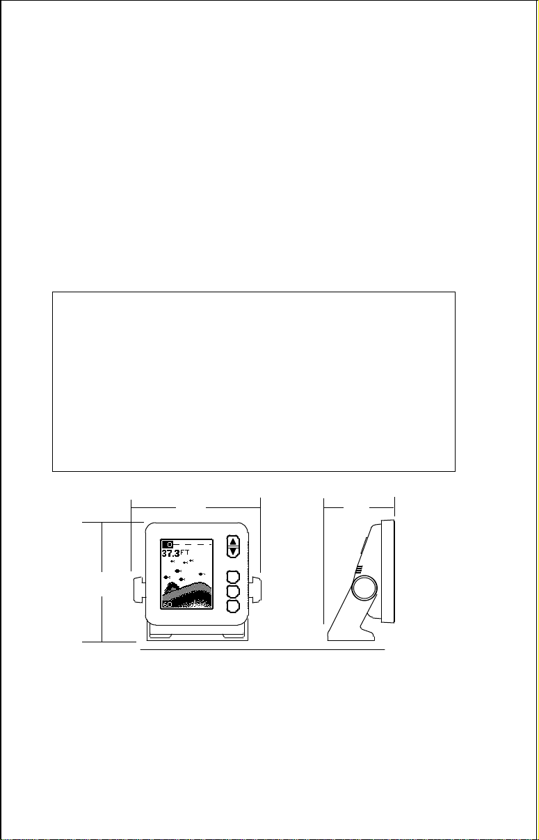
SPECIFICATIONS
Dimensions ...................... 5.9" W x 5.35" H x 3.4" D
Input Voltage.................... 10 - 15 vDC
Current Drain ................... 350 ma (lights off)
........................... 500 ma (lights on)
Transmitter
Frequency.......... 192 kHz
Output Power..... 275 watts (peak-to-peak) (typical)
........................... 34.4 watts (RMS)
Display ........................... 100 pixels (H) x 65 pixels (W)
........................... Supertwist Liquid Crystal Display
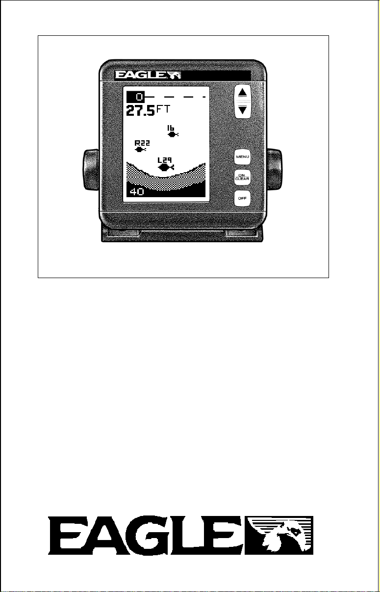
INTRODUCTION
Thank you for purchasing an Eagle sonar. Your MagnaView or MagnaView
Plus is a high quality sonar designed for both professional and novice
fishermen. These units have an automatic feature that finds and displays
the bottom, fish, structure, and more! All you have to do is press the on key.
However, if you wish to fine tune the unit, all you have to do is press the
menu key. The Magna series has powerful features available through
easy-to-use menus.
To get started with your Eagle unit, first read the installation section. This
is where it all begins. Improper installation can cause problems down the
road. After you’ve read the instructions, install the unit, then read the rest
of the manual. The more you know about your unit, the better it will perform
for you. Take this manual for reference when you head for the water.
5.9"
5.35"
NOTICE!
The storage temperature for your unit is from -4 degrees to +167 degrees
Fahrenheit (-20 degrees to +75 degrees Celcius). Extended storage in
temperatures higher or lower than specified will damage the liquid crystal
display in your unit. This type of damage is not covered by the warranty.
For more information, contact the factory customer service department or
your local service center.
3.4"
4
INSTALLATION - Bracket
You can install the MagnaView on the top of a dash or from an overhead
with the supplied bracket. It can also be installed in the dash with an
optional IDA-3 mounting kit. If you use the supplied bracket, you may be
interested in the optional GBSA-1 swivel bracket kit. This converts the
MagnaView's gimbal bracket to a swivel mount which can be used on the
dash or overhead mounting positions. Installation instructions for the in-
dash and swivel mounting kits are supplied with the adapter kits.
Mount the MagnaView in any convenient location, provided there is
clearance when it’s tilted for the best viewing angle. Holes in the bracket’s
base allow wood screw or through bolt mounting. It may be necessary to
place a piece of plywood on the back side of thin panels to reinforce the
panel. Make certain there is enough room behind the unit to attach the
power and transducer cables.
Drill a hole in the dash for the power and transducer cables. The best
location for this hole is immediately under the gimbal bracket. This way, the
bracket covers the hole. The smallest hole the MagnaView's power and
transducer cable connectors can pass through is 3/4". However, you can’t
pass a power or transducer connector and another cable through a 5/8"
hole. Therefore, after drilling the hole, pass the transducer connector up
through the hole from under the dash. Then drop the power cable down
from the front side of the dash. After installing the transducer, route its
cable to the unit by passing it through the hole from under the dash. Slide
the bracket over the hole, then route the transducer and power cables out
the slot in the back of the bracket. Finally, fasten the bracket to the dash.
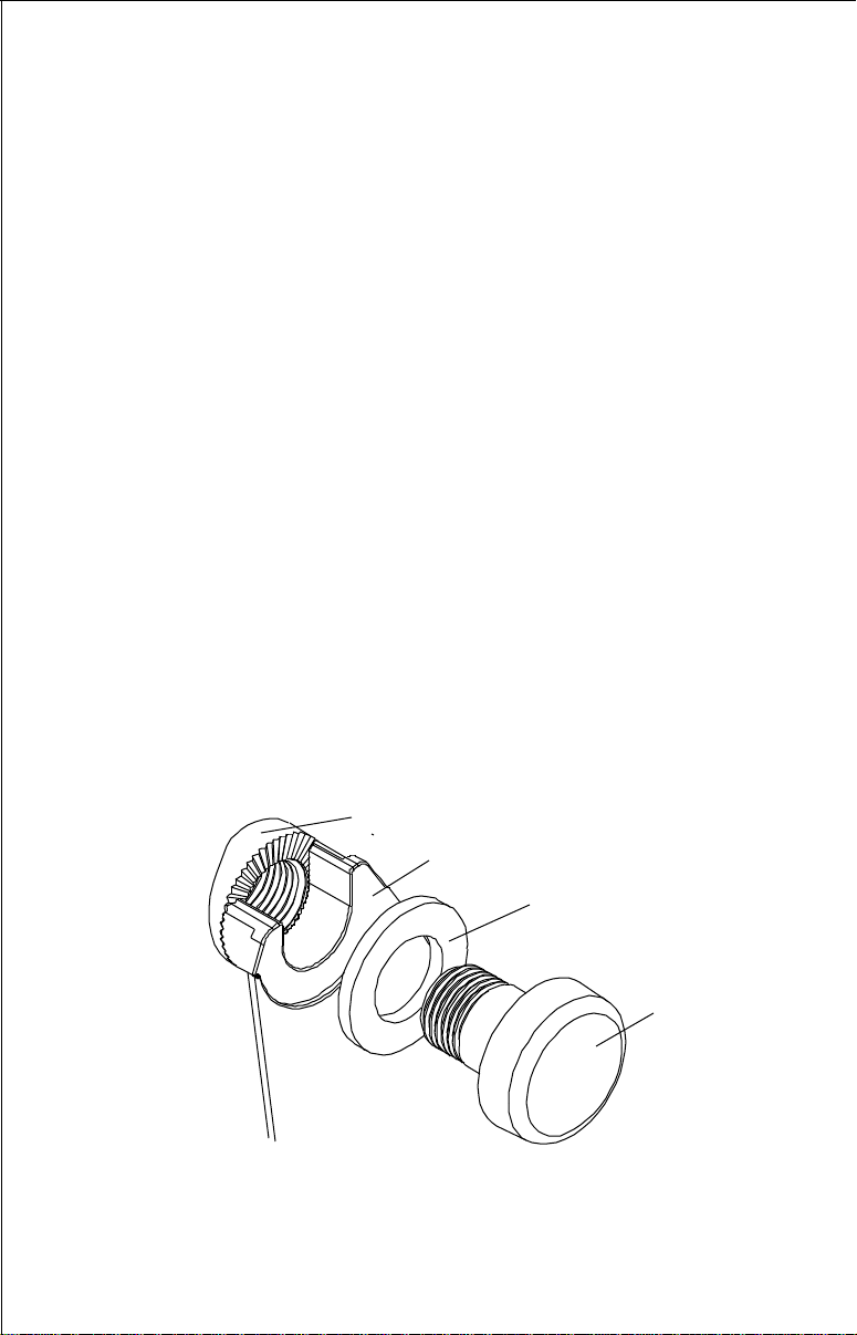
Attach the MagnaView to the gimbal bracket using the supplied gimbal
knobs and washers as shown above.
GIMBAL KNOB
WASHER
GIMBAL BRACKET
MAGNAVIEW
5
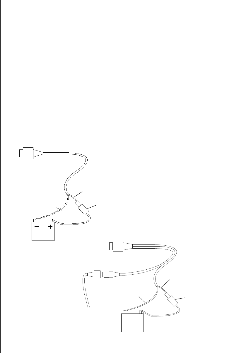
POWER CONNECTIONS
The MagnaView works from a 12 volt DC system only. For the best results,
run the power cable directly to the boat’s battery. Keep the power cable
away from other boat wiring, especially the engine’s wires. This will give
the best isolation from electrical noise. If the supplied cable is not long
enough to reach the battery, splice #18 gauge insulated wire to it. If you do
extend the power cable, make certain to attach the in-line fuse holder
supplied with the MagnaView to the battery or power source. This will
protect both the unit and the power cable in the event of a short. Use only
a 3-amp fuse.
You can also attach the power cable to an accessory or power buss,
however, you may have problems with electrical interference.
These units have reverse polarity protection. No damage will occur if the
power wires are reversed. However, the unit will not work until the wires
are attached correctly.
BLACK
WIRE
12 VOLT
BATTERY
RED
WIRE
3 amp
FUSE
MAGNAVIEW
WIRING
RED
WIRE
BLACK
WIRE
TO
SPEED/
TEMP
SENSOR
12 VOLT
BATTERY
3 amp
FUSE
MAGNAVIEW
PLUS
WIRING
6
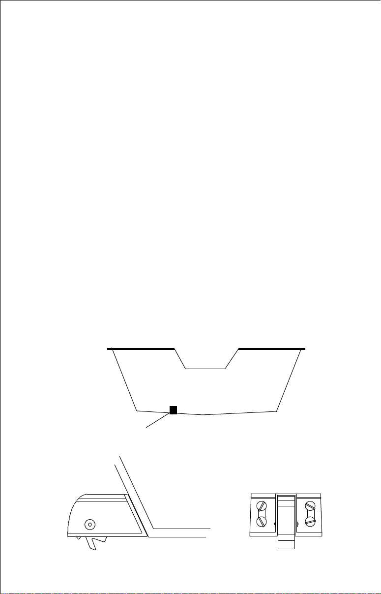
SPEED/TEMPERATURE SENSOR INSTALLATION -
(MagnaView Plus Only)
Mount the speed/temp sensor on the boat’s transom in a location where the
flow of water is the smoothest. There should be a minimum of turbulence
and air bubbles in the chosen location. The port (left) side of the transom
is preferred, however, the starboard (right) side can be used if necessary.
Do not mount the speed sensor behind strakes, ribs, or thru-hull fittings.
These will disturb the flow of water to the speed sensor. In a typical
installation, the speed sensor is mounted six to twelve inches from the
centerline of the hull. The sensor must always be in the water to function
properly. Make certain the chosen location is in the water even at high
speed or when the boat is on plane.
Once you determine the proper location, place the sensor on the transom.
Make certain the sensor’s bottom is flush with the bottom of the hull. Mark
the transom in four places, two in each slot. Drill a 5/32" mounting hole at
each location. Mount the sensor to the hull with four #10 stainless steel
screws. Use a good grade of caulking compound to seal the screws.
Adjust the sensor so it is flush with the bottom of the hull and tighten the
screws. If the base of the transom has a radius, fill the gap between the
transom and the sensor with caulking compound. This will help ensure a
smooth water flow.
Route the sensor cable to the in-line connector on the MagnaView Plus’
power cable. The speed/temp sensor is now ready for use.
SIDE VIEW REAR VIEW
GOOD LOCATION
7
KEYBOARD BASICS
The unit sounds a tone when you
press any key. This tells you the
unit has accepted a command.
ON/CLEAR
Use this key to turn the unit on. It
also clears menu selections and
the menus from the screen.
OFF
This key turns the unit off.
MENU
The MagnaView and MagnaView Plus have many features that are
accessed with this key. To see the first menu, press the MENU key. To see
the other menus, press the MENU key repeatedly.
UP and DOWN ARROWS
Use these keys to adjust virtually every feature and function on the unit.
NOTE: The up arrow key also stops the chart when no menus are
displayed. In other words, anytime you wish to stop the chart, first make
certain no menu is on the screen. Now press the up arrow key. The chart
freezes and the word “STOP” appears at the top of the screen. To start the
chart, press the up arrow key again.
DISPLAY - General
The lights flash for about ten seconds when the MagnaView is turned on.
Three menus appear, one after the other. The menus are the lights
(LAMP), feet-meter selection (FEET/METER), and contrast adjustment
(DARK/LIGHT). To turn the lights on, press
the up arrow key. To switch from feet to
meters, press the down arrow key when the
proper menu appears. To adjust the contrast,
wait for the DARK/LIGHT menu to appear.
Now press the up arrow key to darken the
screen, the down arrow to lighten it. The
menus disappear after a few seconds. If you
don’t want to wait, press the ON/CLEAR key
to clear the menus from the screen.
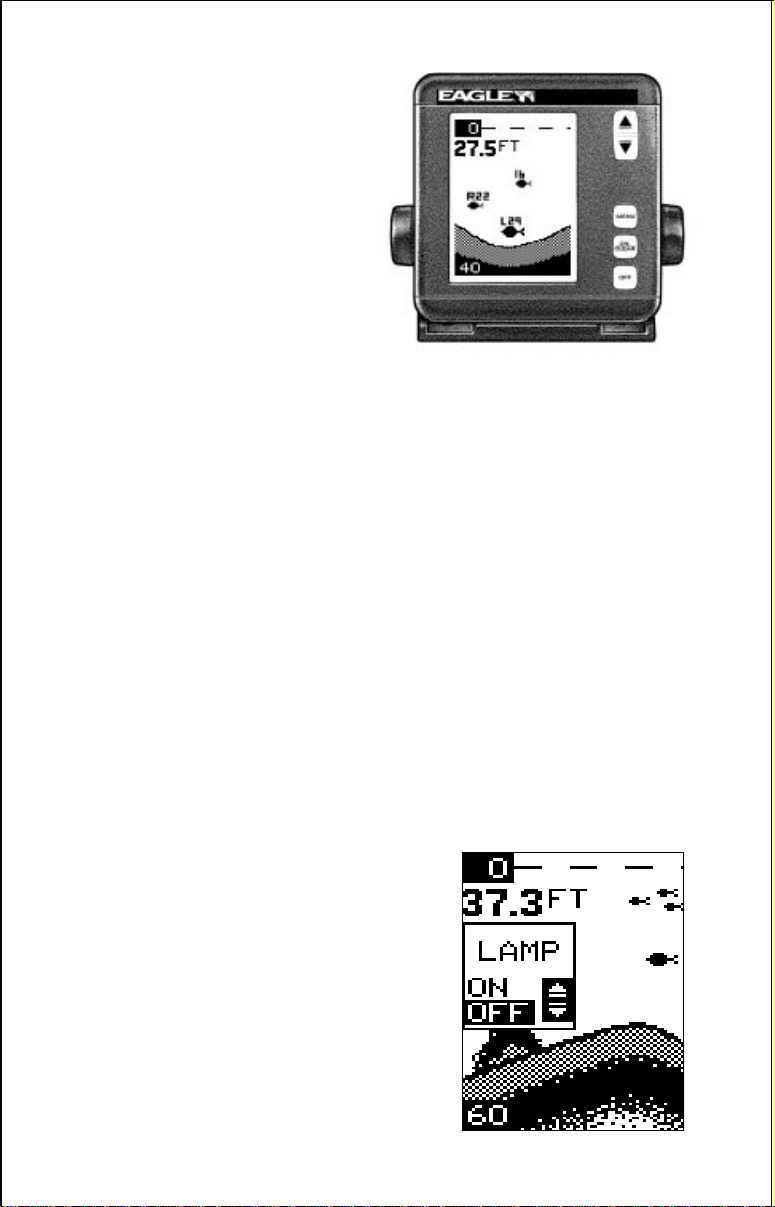
When the MagnaView is first turned on, the
display appears similar to the one at right.
The unit is in the automatic mode and the Fish
MagnaViewMagnaView
MagnaViewMagnaView
MagnaView
8
ID feature is on. The depth range displays on the upper left side of the
screen. On the screen at the bottom of the previous page, the range is from
0 to 60 feet and the bottom depth is 37.3 feet.
OPERATION
MENUS
The MagnaView and MagnaView Plus use menus to guide you through the
unit’s functions and features. The menu key accesses these features,
allowing you to customize the unit to your particular needs and water
conditions. All you have to do to leave one menu and enter another is press
the menu key repeatedly. If you ever get lost in the menus, simply press
the ON/CLEAR key. This clears the menus from the screen.
Menus change depending on the mode the unit is in. For example, if the
automatic mode is turned off, the sensitivity menu changes from “AUTO
SENS” to “MAN SENS.” Other messages may appear in menu boxes or
new menus can appear, again depending on previous selections.
On the screen shown on the previous page, the lamp menu is showing.
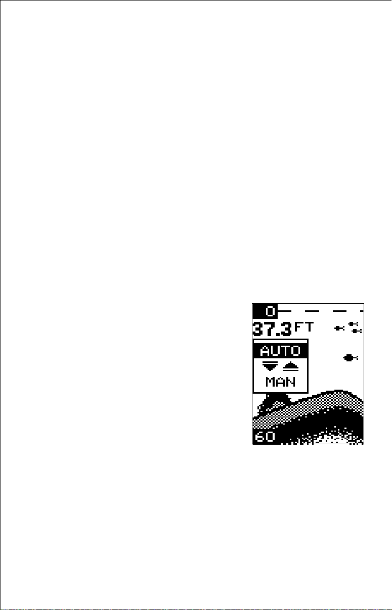
AUTOMATIC
When the MagnaView is first turned on, the
automatic feature is enabled. This feature
automatically adjusts the unit’s range and
sensitivity according to water conditions. It
always keeps the bottom depth displayed in
the lower portion of the screen.
To turn the automatic feature off, press the
menu key until the AUTO/MAN menu ap-
pears. Now press the down arrow key. This
highlights the letters “MAN.” The unit is now
in the manual mode. Wait a few seconds and
the menu will scroll off the screen’s left side.
Pressing the ON/CLEAR key also clears it. To turn the automatic feature
on again, repeat the above steps, except this time press the up arrow key.
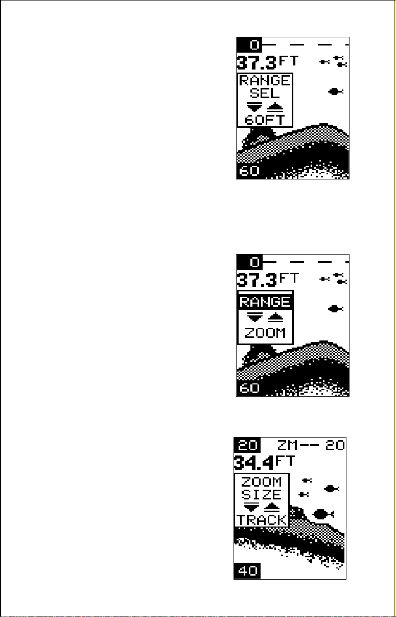
RANGE
You can’t adjust the range when the MagnaView is in the automatic mode.
It is adjustable when the unit is in the manual mode, however. To do so,
first put the unit in the manual mode. Now press the ON/CLEAR key to
clear the screen. Then press the menu key until the “RANGE SEL” menu
appears as shown below. The current range shows at the bottom of the
9
menu. In this case, the range is 60 feet. Now
press the up arrow key to decrease the range,
the down arrow key increases the range. After
you select the desired range, press the ON/
CLEAR key to clear the display. If you wait a
few seconds, it will automatically clear.
The MagnaView and MagnaView Plus have
the following ranges:
10, 20, 40, 60, 120, 240, 480, and 900 feet.
and
5, 10, 20, 40, 60, 100, 200, and 300 meters.
ZOOM
The zoom feature enlarges all echoes on the
screen. If the unit is in the automatic mode, it
tracks the bottom signal, always keeping it
near the bottom of the screen. This lets you
see small detail, at the same time enlarging all
echoes that appear on the screen. The unit
doesn’t track the bottom in the manual mode,
and the adjustments are slightly different.
Zoom - Automatic Operation
To zoom the display, first press the MENU
key until the RANGE/ZOOM menu appears
as shown at right. Now press the down arrow
key. This switches the unit into the zoom
mode. A new menu immediately appears as
shown below.
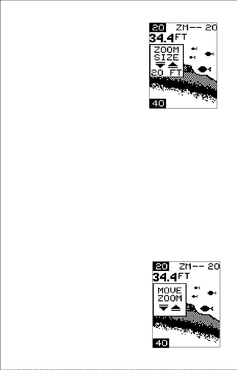
This is the zoom size menu. Zoom size is the
distance between the upper limit and the
lower limit. The upper limit shows at the top
left corner of the screen. The lower limit is in
the bottom left corner. For example, if the
upper limit is 40 feet and the lower limit is 70
feet, the zoom window size is 30 feet. The
word “TRACK” appears in this menu when
you first activate the zoom as shown at right.
10
This means the MagnaView is tracking the
bottom in a zoom window, always keeping it
on the display.
Press the up arrow key to decrease the
zoom size, press the down arrow key to
increase the zoom size.
When the unit is switched into the zoom
mode, the letters “ZM” appear at the top of
the screen. The zoom window size displays
in the top right corner of the screen.
On the screen shown above, the zoom size has been changed to 20 feet.
To turn the zoom feature off, press the menu key until the RANGE/ZOOM
menu appears. Now press the up arrow key. This switches the unit into
the range mode, which turns the zoom feature off.
The MagnaView and III Plus have the following zoom ranges:
10, 20, 30, 60, 120, 240, and 480 feet
and
5, 10, 20, 30, 50, 100, and 150 meters.
Zoom - Manual Operation
To operate the zoom feature when the MagnaView is in the manual mode,
first press the menu key. Then press the down arrow key in the RANGE/
ZOOM menu to place the Magna in the zoom mode. The zoom size menu
automatically appears next. You can change the zoom size by pressing
the up or down arrows. After you select the desired zoom size, press the
menu key until the “MOVE ZOOM” menu appears. This menu lets you
move the zoom window up or down in
one foot
increments by pressing the arrow keys. Thus,
you can move the zoom window up towards
the surface, down to the bottom, or anywhere
in between. The window stays where you put
it. It doesn’t track the bottom signal.
To turn the zoom feature off, press the menu
key until the RANGE/ZOOM menu appears.
Now press the up arrow key. This switches
the unit into the range mode, which turns the
zoom feature off.
 Loading...