

Druck PACE1000, PACE5000, PACE6000 Operating Manual

This document is the property of Druck Limited and may not, either in part or whole, be copied or otherwise
any way to third parties, nor stored in any data processing system, without the
Pressure measurement
for research & industry
Druck Limited
Fir Tree Lane
Groby
Leicester LE6 0FH
England
Tel: 0116 231 7100
PACE Series
Standard Commands for
Programmable Instruments
Communications
Manual
K0472
© Druck Limited
2009
reproduced, communicated in
express written authority of Druck Limited.
Page 1 of 108 K0472 Issue No. 1
Do Not Print This Page

A
mendment Record
Iss No Date C/N No Originator Typed
1 01/05/09 - Robert Lee Robert Lee 128319 New document
Workflow
No.
Approvals
Engineering
SHAN
Q
Marketing
M COLLINS
Engineering
P BRADLEY
Publications
R LEE
Engineering
R GAJEWSKI
Amendments
Page 2 of 108 K0472 Issue No. 1
Do Not Print This Page

Print Instructions
Print colour on white, double sided as supplied on disk.
Print on paper to 110 gsm, Silverblade matt art, wiro-bind in 270 gsm covers.
Page size 180 x 230 mm.
Note: this document is normally published electronically and shipped on UD-0001.
Page 3 of 108 K0472 Issue No. 1
Do Not Print This Page

Page 4 of 108 K0472 Issue No. 1
Do Not Print This Page
GE
g
Sensing & Inspection Technologies
PACE
Pressure Automated Calibration Equipment
SCPI Remote Communications Manual - K0472

Trademarks
All product names are trademarks of their respective company.
© The General Electric Company all rights reserved.

Introduction
This technical manual provides SCPI protocol instructions for the remote control of the
PACE Series indicators and controllers.
Safety
The manufacturer has designed this product to be safe when operated using the
procedures detailed in this manual. Do not use this product for any other purpose than
that stated.
This publication contains operating and safety instructions that must be followed to
make sure of safe operation and to maintain the equipment in a safe condition. The
safety instructions are either warnings or cautions issued to protect the user and the
equipment from injury or damage.
Use qualified* programming technicians and good engineering practice for all
procedures in this publication.
Pressure
Do not apply pressure greater the maximum safe working pressure to the PACE Series.
Maintenance
The PACE Series must be maintained using the manufacturer’s procedures and should be
carried out by authorised service agents or the manufacturer’s service departments.
Technical Advice
For technical advice contact the manufacturer or subsidiary.
* A programming technician must have the necessary specialist knowledge of
programming, technical knowledge and documentation to carry out the required work
on the PACE Series.
Associated Documents:
A beginners Guide To SCPI by Barry Eppler, Published by Addison-Wesley Publishing
Company Inc. for Hewlett Packard (ISBN 0-201-56350-9)
K0472 Issue No. 1 i

Table of Contents
Preliminary pages
Introduction ................................................................................................................................. i
Safety ................................................................................................................................. i
Table of contents (this table) .......................................................................................................................... ii
List of Illustrations ................................................................................................................................. v
List of Tables ................................................................................................................................. v
Abbreviations ................................................................................................................................. vi
Pressure measurement units......................................................................................................................... vi
Code Definitions ................................................................................................................................. vii
Pressure unit conversions ............................................................................................................................... viii
Section page
1 INTRODUCTION .......................................................................................................... 1-1
1.1 General ................................................................................................................................. 1-1
1.2 Remote/Local Operation 1-1
2 COMMAND STRUCTURE .............................................................................................. 2-1
2.1 Notation ................................................................................................................................. 2-1
2.2 Message Terminators........................................................................................................................... 2-1
2.3 Program headers ................................................................................................................................. 2-3
2.4 SCPI data types ................................................................................................................................. 2-4
3 STATUS SYSTEM .......................................................................................................... 3-1
3.1 Output queue ................................................................................................................................. 3-3
3.2 Standard event group.......................................................................................................................... 3-4
3.3 Operation status group ..................................................................................................................... 3-5
3.4 Status byte group 3-7
3.5 Instrument errors 3-10
4 COMMAND AND QUERY SUMMARY 4-1
4.1 Command structure..............................................................................................................................4-1
CALibration ................................................................................................................................. 4-3
:CAL:PRES:POIN ................................................................................................................................. 4-3
:CAL:PRES:ACC ................................................................................................................................. 4-4
:CAL:PRES:VAL ................................................................................................................................. 4-5
:CAL:ZERO:VALV ................................................................................................................................. 4-6
:CAL:ZERO:VALV:STAT............................................................................................................................. 4-7
:CAL:ZERO:AUTO ................................................................................................................................. 4-8
INPut ................................................................................................................................. 4-9
INP:LOG ................................................................................................................................. 4-9
INSTrument .................................................................................................................................4-10
ii K0472 Issue No. 1

Section page
:INST:CAT ................................................................................................................................. 4-10
:INST:CAT:ALL ................................................................................................................................. 4-11
:INST:LIM ................................................................................................................................. 4-12
:INST:SENS:CALD ................................................................................................................................. 4-13
:INST:SENS:FULL ................................................................................................................................. 4-14
:INST:SN ................................................................................................................................. 4-15
:INST:VERS ................................................................................................................................. 4-16
OUTPut ................................................................................................................................. 4-17
:OUTP:STAT ................................................................................................................................. 4-17
:OUTP:LOG ................................................................................................................................. 4-18
SENSe 4-19
:SENS:PRES .................................................................................................................................4-19
:SENS:PRES:INL ................................................................................................................................. 4-20
:SENS:PRES:SLEW .................................................................................................................................4-21
:SENS:PRES:BAR ................................................................................................................................. 4-22
:SENS:PRES:RANG ................................................................................................................................. 4-23
:SENS:PRES:RES ................................................................................................................................. 4-24
:SENS:PRES:CORR:HEAD.......................................................................................................................4-25
:SENS:PRES:CORR:HEAD:STAT............................................................................................................ 4-26
:SENS:PRES:CORR:HEAD:OFFS........................................................................................................... 4-27
:SENS:PRES:CORR:HEAD:OFFS:STAT................................................................................................4-28
:SENS:PRES:CORR:VOL .......................................................................................................................... 4-29
:SENS:PRES:FILT ................................................................................................................................. 4-30
:SENS:FILT:LPAS:BAND........................................................................................................................... 4-31
:SENS:FILT:LPAS:FREQ............................................................................................................................4-32
:SENS:FILT:LPAS:STAT .............................................................................................................................4-33
SOURce ................................................................................................................................. 4-34
:SOUR:PRES:COMP ................................................................................................................................. 4-34
:SOUR:PRES:EFF ................................................................................................................................. 4-35
:SOUR:PRES:INL .................................................................................................................................4-36
:SOUR:PRES:INL:TIME.............................................................................................................................4-37
:SOUR:PRES:LEV:IMM:AMPL ................................................................................................................4-38
:SOUR:PRES:LEV:IMM::VENT................................................................................................................ 4-39
:SOUR:PRES:RANG ................................................................................................................................. 4-41
:SOUR:PRES:SLEW ................................................................................................................................. 4-42
:SOUR:PRES:SLEW:MODE.....................................................................................................................4-43
:SOUR:PRES:SLEW:OVER 4-44
K0472 Issue No. 1 iii

Section page
STATus ................................................................................................................................. 4-45
:STAT:OPER:COND ................................................................................................................................. 4-45
:STAT:OPER:ENAB ................................................................................................................................. 4-46
:STAT:OPER:EVEN ................................................................................................................................. 4-47
:STAT:OPER:PRES:COND........................................................................................................................ 4-48
:STAT:OPER:PRES:ENAB.........................................................................................................................4-49
:STAT:OPER:PRES:EVEN ......................................................................................................................... 4-50
SYSTem ................................................................................................................................. 4-51
:SYST:ERR ................................................................................................................................. 4-51
:SYST:DATE ................................................................................................................................. 4-53
:SYST:SET .................................................................................................................................4-54
:SYST:TIME .................................................................................................................................4-55
:SYST:COMM:SER:CONT ........................................................................................................................ 4-56
:SYST:COMM:SER:BAUD........................................................................................................................4-57
:SYST:COMM:SER:TYPE:PAR.................................................................................................................4-58
:SYST:COMM:GPIB:SELF:ADDR ...........................................................................................................4-59
:SYST:AREA ................................................................................................................................. 4-60
:SYST:PASS:CDIS ................................................................................................................................. 4-61
:SYST:PASS:CEN .................................................................................................................................4-62
:SYST:PASS:CEN:STAT.............................................................................................................................4-63
:SYST:VERS ................................................................................................................................. 4-64
UNIT .................................................................................................................................4-65
:UNIT:PRES ................................................................................................................................. 4-65
UNIT:PRES:DEF .................................................................................................................................4-66
4.2 * Common SCPI commands - three letter commands, prefixed by * ........................... 4-68
*CLS ................................................................................................................................. 4-68
*ESE ................................................................................................................................. 4-69
*ESR .................................................................................................................................4-70
*IDN? ................................................................................................................................. 4-71
*SRE .................................................................................................................................4-72
*STB? ................................................................................................................................. 4-73
Instrument control commands - three letter commands, prefixed by :. .....................4-74
:GTL .................................................................................................................................4-74
:LOC ................................................................................................................................. 4-75
5 ERRORS .......................................................................................................... 5-1
iv K0472 Issue No. 1

Figure page
Figure 1-1 System Model.............................................................................................................................. 1-1
Figure 2-1 General Command Syntax ................................................................................................... 2-1
Figure 2-2 Command Syntax ..................................................................................................................... 2-2
Figure 2-3 Response Syntax .......................................................................................................................2-3
Figure 4-1 Command and Query Summary........................................................................................ 4-2
Table page
3-1 Standard Event Register ..................................................................................................................... 3-12
3-2 Operation Status Register.................................................................................................................. 3-14
3-3 Status Byte Register..............................................................................................................................3-16
5-1 Errors -100 to -199 ................................................................................................................................ 5-1
5-2 Errors -200 to -299 ................................................................................................................................ 5-2
5-3 Errors -300 to -400 ................................................................................................................................ 5-2
5-3 Errors +201 to +212 .............................................................................................................................. 5-2
The following abbreviations are used in this manual; abbreviations are the same in the
singular and plural.
aAbsolute
ASCII American Standard Code for Information Interchange
e.g. For example
Fig. Figure
ft Foot
g Gauge
GPIB General purpose interface bus
i.e. That is
IEEE 488 Institute of Electrical and Electronic Engineers standard 488
(for programmable devices with a digital interface)
mMetre
max Maximum
mbar Millibar
min Minute or minimum
No. Number
RS232 Serial communications standard
Rx Receive data
SCPI Standard commands for programmable instruments
Tx Transmit data
+ve Positive
-ve Negative
°C Degrees Celsius
°F Degrees Fahrenheit
K0472 Issue No. 1 v

The following units are used in this manual
ATM at mosph ere
BAR bar
CMH2O centimetres of water at 20°C
CMHG centimetres of mercury
FTH2O feet of water at 20°C
FTH2O4 feet of water at 4°C
HPA hecto Pascals
INH2O inches of water at 20°C
INH2O4 inches of water at 4°C
INH2O60 inches of water at 60°F
INHG inches of mercury
KG/CM2 kilogrammes per square centimetre
KG/M2 kilogrammes per square metre
KPA kilo Pascals
LB/FT2 pounds per square foot
MH2O metres of water
MHG metres of mercury
MMH2O millimetres of water
MMHG millimetres of mercury
MPA mega Pascals
PA Pascals
PSI pounds per square inch
TORR torr
MBAR millibar
vi K0472 Issue No. 1
PACE Series SCPI Manual
Pressure
out
logic
logic
Pressure
in
SOURce
sub-system
UNITs
sub-system
CALibrate
sub-system
INPut
sub-system
SENSe
sub-system
INSTrument
sub-system
OUTPut
sub-system
SYSTem
sub-system
S TATu s
sub-system
1INTRODUCTION
1.1 General
The IEEE 488 and RS232 interfaces of the PACE Series provide remote control of the
instrument from a suitable computer or controller. The SCPI protocol enables any instrument
with a SCPI facility to be controlled using the same commands. The PACE Series use the full
SCPI command set and the defined SCPI syntax.
The following sections describe and define each instrument command used by the PACE
Series. The commands for the aeronautical option and the sensor calibration module option
are described and defined in separate sections. Each section contains a quick reference
structure of the relevant commands.
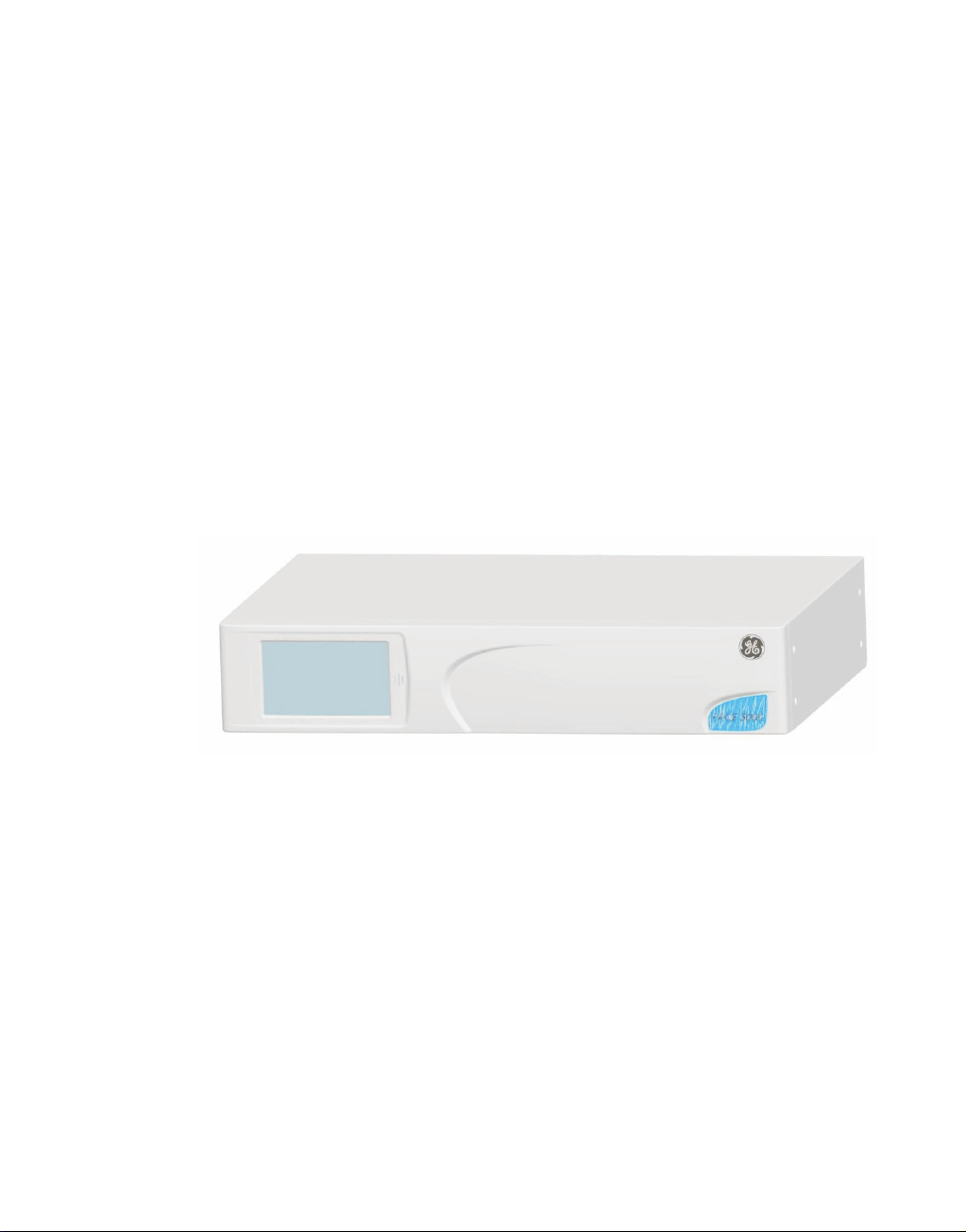
Figure 1-1 System Model
System Model
SCPI starts with a high-level block diagram of the measurement functions of the instrument.
Each functional block is broken down into smaller block diagrams. SCPI contains a hierarchy
of commands called a subsystem that maps directly to the hierarchy of the block diagram.
1.2 Remote/Local Operation
Most commands received over the SCPI interface automatically puts the PACE Series into
remote control mode and disables the front panel touch-screen. Sending the LOC command
returns the PACE Series to local control mode and enables the front panel touch-screen .
K0472 Issue No. 1 1-1

1 Description
intentionally left blank
K0472 Issue No. 1 1-2

PACE Series SCPI Manual
root Level 1 Level 2
AB
C
D
E
F
G
H
J
2COMMAND STRUCTURE
This section describes the structure of the commands and data sent and received by a PACE
Series Controller/Calibrator.
2.1 Notation
All SCPI commands are based on a hierarchical tree structure consisting of key words and
parameters. Associated commands are grouped together under a common node in the
hierachy.
In the command tree the command A is the root command. A tree pointer is used to decode
the SCPI commands. At power-up the pointer goes to the root command.
2.2 Message Terminators
All SCPI commands are terminated by line feed i.e., either <newline> (ASCII character,
decimal 10), EOI for IEEE. After receiving a termination character the tree pointer returns to
the root command.
Colon
A colon moves the current path down one level in the command tree, (e.g., the colon in
SOURCE:PRESSURE specifies PRESSURE the is one level below SOURCE). When the colon is
the first character of the command, it specifies that the next command is a root level
command (e.g., :SOURCE specifies that SOURCE is a root level command).
Semicolon
A semicolon separates two commands in the same message without changing the tree
pointer.
(e.g., with reference to the tree):A:B:E;F;G
This equivalent to sending three messages:
:A:B:E
:A:B:F
:A:B:G
K0472 Issue No. 1 2-1

2 Command Structure
Commas
If a command requires more than one parameter, separate adjacent parameters by using a
comma. A commas does not affect the tree pointer.
(e.g.) :SYSTEM:TIME 10,25,30
To execute a command the full path to the command must be specified:
(e.g.) :OUTPut:STATe ON
This turns the pressure controller on.
Note:
There must be a space between the command words and the parameter. In the above
example there is a space between :STATe and ON.
SCPI commands are not case sensitive and may have a short form. In this manual, upper
case letter identify the short form.
(e.g.) :OUTP is the short form of OUTPUT.
Some nodes can be the default node and these key words are optional when programming
the command. The instrument processes the command, with the same effect, with or
without the option node. In this manual [] enclose [default notes].
(e.g.) :SOURce[:PRESsure:][:LEVel][:IMMediate][:AMPlitude] 5.0
can be sent as
:SOURce:PRESsure:LEVel 5.0
or
:SOURce 5.0
This sets the set-point to 5.0
K0472 Issue No. 1 2-2

PACE Series SCPI Manual
2.3 Program Headers
Program headers are keywords that identify a command, instruments accept both upper
and lower case characters in a program header. There are two types of program header,
common command headers and instrument control headers; each header can be a
command or a query.
Common Command and Query Headers
The common command and query program header syntax, specified in IEEE 488.2, are
defined as follows:
Command
*<PROGRAM MNEMONIC>
Query
*<PROGRAM MNEMONIC>?
Instrument Control Command and Query Headers
The instrument control command and query program header syntax controls and extracts
data from the instrument as follows:
Command
:<MNEMONIC>
:<MNEMONIC> <PARAMETER>
Query
:<MNEMONIC>?
Instrument command headers can have a numeric suffix to identify each of several cases of
the same header; the numeric suffix applies to both the long and short forms. All commands
headers without a numeric suffix assume the value 1.
e.g.,
:OUTPut:LOGic1?
is the same as
:OUTPut:LOGic:?
Queries
A query is a program header with an attached question mark character (?). On receiving a
query, the current settings are loaded in the output buffer. A query does not affect the
operation or set-up of the instrument.
When the parameter of a command contains enumerated character data, both long form
and short form are recognised. A query causes the return of data in the short form.
Querying numeric parameters causes the resulting data to be returned in the units selected
by the instrument unless specified otherwise.
K0472 Issue No. 1 2-3

2 Command Structure
2.4 SCPI Data Types
A variety of data types can be sent to the instrument as parameters or sent out from the
instrument as response data.
Decimal Data
All normal decimal expressions are accepted including optional signs, decimal point and
scientific notation.
Note:
This includes floating point data.
The following are valid:
123
45.67
-2.6
4.6e-10
.76
A suffix multiplier can be added to the numeric value.
:SOUR 100 m
would set the programmable output to 0.1 units (100m units).
The multipliers supported are:
Mnemonic Multiplier
A1e-18
G1e+9
K1e+3
M1e-3
T1e+12
If a real value is sent to the instrument when an integer is expected, it will be rounded to an
integer.
Integer Data
Integer data are whole numbers (containing no decimal places). A query of an integer value
returns numbers containing no decimal places.
Note:
Integer values can be specified in binary, octal or hexadecimal formats using the suffix letters
(upper or lower case) B, Q and H respectively.
e.g., #B1010 binary representation of 10
#Q71 octal representation of 57
#HFA hexadecimal representation of 250
Hexadecimal digits A-F can be in upper or lower case.
K0472 Issue No. 1 2-4

PACE Series SCPI Manual
Enumerated Character Data
Enumerated characters are used for data that has a finite number of values; enumerated
parameters use mnemonics to represent each valid setting.
The mnemonics have long and short forms just like command mnemonics.
Example:
:SOURce:PRESsure:SLEW:MODE MAX imum
selects the maximum rate mode.
A query of an enumerated parameter always returns the short form data in upper case.
Example:
:SOURce:PRESsure:SLEW:MODE?
queries rate mode, reply:
MAX
Boolean Data
Boolean data can only be one of two conditions; the numbers 1 and 0.
Example:
:OUTPut:STATe 1
A query of boolean data always returns 1 or 0.
String Data
String data can contain any of the ASCII characters. A string must start with a double
"quote" (ASCII 34) or a single `quote` (ASCII 39) and end with the same
Note:
Characters in a string in either double "quote" or single `quote` are case sensitive.
Example:
:SOURCe[:PRESsure]:RANGe ‘2BARG’
or
:SOURCe[:PRESsure]:RANGe “2BARG”
selects the 2 bar g range.
A query of a string parameter always returns the string in double "quotes".
character.
K0472 Issue No. 1 2-5

2 Command Structure
Intentionally left blank
K0472 Issue No. 1 2-6

PACE Series SCPI Manual
3 STATUS SYSTEM
The status reporting system informs the external controller that an event has occurred. This
information is in the form of a service request (SRQ) using IEEE 488 or an SRQ message using
RS232.
The PACE Series uses status reporting as defined in IEEE 488.2 with the implementation of
status registers.
The OPERation status registers have been implemented to comply with the SCPI protocol.
These are registers where the individual bits are summary bits of the status of the
instrument. Since the SCPI protocol does not include pressure instruments, bit 10 of both
these registers are used as a pressure summary bit. This pressure summary bit is expanded
to two, 16 bit registers (Bit 15 is not used and is always zero).
The only bit implemented in the Operation status register is bit 10 (summary of the pressure
operation status).
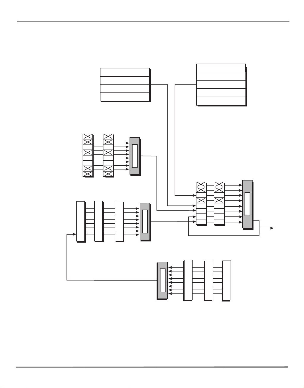
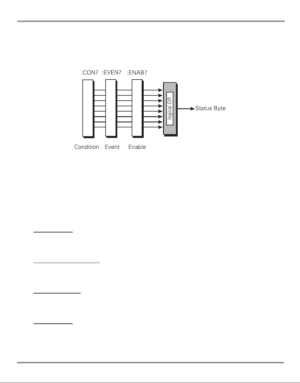
A summary bit is the final output of a data structure, it is a single bit that shows the status of
one or more related events in the instrument. The basic structure of a summary bit
•Condition register
•Event register
• Enable register
• Logical ANDing of the Event and Enable registers
• Summary bit that summarises the result using OR logic
Condition Register
This register shows the current status of the device. The condition register is constantly
updated - the bits in the register are set or reset showing the current condition.
Event Register
The event register shows an event that occurs in the condition register (a condition bit goes
from low to high). This condition change is stored and only reset when the event register is
read or the *CLS command sent.
Enable Register
This register allows the results of the event register to pass through to the next cascaded
register and enables the user to select the event that should generate the final SRQ event.
K0472 Issue No. 1 3 - 1
3 Status System
logical OR
MAV
ESB
OSB
MSS
MAV
ESB
OSB
Status Byte
EN 8 bitEV
*SRE
STAT:OPER
:ENAB
*STB?
SERIAL POLL
STAT:OPER
:PRES:ENAB 511
Pressure Operations 15 bit
STAT
:OPER
:EVENT?
STAT:OPER
:PRES:ENAB?
Operation Status 16 bit
logical OR
CEV EN
logical OR
C
EVEN
Output Queue
Message
Message
Message
Message
SYST:ERR?
*SRE
Error Queue
Error Message
Error Message
Error Message
Error Message
Error Message
logical OR
QYE
CME
EXE
QYE
CME
EXE
Standard Event
EV EN 8 bit
*ESR? *ESE
MSS
EAV
EAV
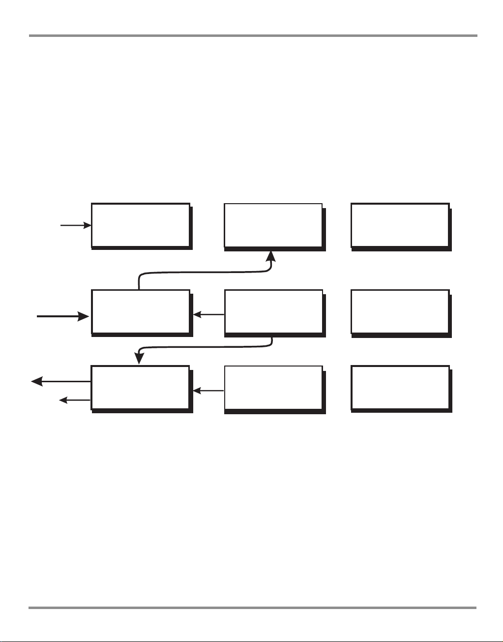
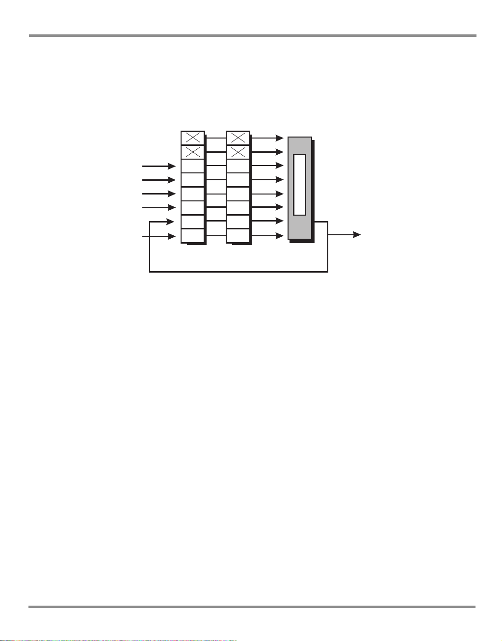
The status system implemented in the instrument is shown in the following diagram:
Note:
Initial values of registers are 0, with the queues empty.
Key:
C = Condition - variable values
EV = Latched values
EN = Bit mask
K0472 Issue No. 1 3 - 2
Figure 3-1 Status System

PACE Series SCPI Manual
3.1 Output queue
The output queue is a text readable data queue that is read through the IEEE 488 talk
command. The queue is cleared by reading all elements in it or by the *CLS command.
Every time a query has been successfully completed, the response, in a text readable format
is placed at the end of the output queue. If the MAV bit in the "Status Byte" was previously
cleared it will be set . The output queue can contain up to 256 characters. If there is not
enough space in the output queue for a new message, the error -350, "Queue overflow" will
be placed into the error queue and the most recent output message will be lost.
K0472 Issue No. 1 3 - 3
3 Status System
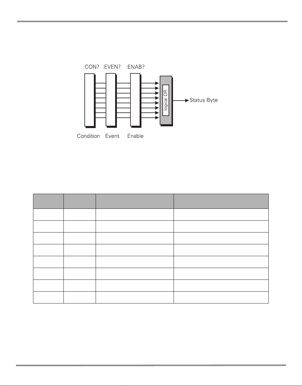
3.2 Standard event group
The standard event group are 8 bit registers that are read by the IEEE 488 standard
commands. The event register is cleared by reading it; the event and enable registers are
cleared by the *CLS command.
Bits within the standard event condition register are set by system errors and events. In
addition to setting the status bits, a text message will be placed in the error queue. The ESB
bit in the status byte sets if the associated bit in the event enable register is set. The enable
register may be set through the *ESE command so that selected standard events cause the
ESB bit to be set. The system events that set each bit are as follows:
Bit Name Description Meaning/data
0 OPC Not used Reserved currently returns 0
1 RQC Not used Reserved currently returns 0
2 QYE -400 to -499 Query errors
3 DDE Not used Reserved currently returns 0
4 EXE -200 to -299 Execution errors
5 CME -100 to -199 Command errors
6 URQ Not used Reserved currently returns 0
7 PON Not used Reserved currently returns 0
Table 3-1 Standard Event Register
K0472 Issue No. 1 3 - 4
PACE Series SCPI Manual
3.3 Operation status group
The operation status group are 16 bit registers that are read by the STAT:OPER commands.
The event register is cleared by reading it; the event and enable registers are cleared by the
*CLS command.
When a standard operation condition occurs an appropriate bit is set in the condition
register (this clears when the condition no longer exists). The bit is then latched in the event
register. If the associated bit in the enable register is set, the OPR bit in the status byte sets.
The enable register may be set through the STAT:OPER:ENAB command so that only selected
standard operation events cause the OPR bit to set.
Problems can occur with some IEEE 488 controllers reading 16 bit unsigned numbers. All
registers in this group do not use bit 15. The enable bit cannot be set and when read returns
0. The condition register is defined as follows:
Vent complete
This signal occurs when the controller has been requested to vent and the vent has
completed or timed out.
Range change complete
This signal occurs when the controller has been requested to perform a range change and
the range change is complete.
In-Limits reached
This signal is set every time the controlled pressure is within the specified limits. The signal is
only generated if the pressure has been within limits for a user defined wait time period.
Zero complete
This signal is generated when a manual or timed zero is complete. If the zero times out then
this signal is also generated.
K0472 Issue No. 1 3 - 5

3 Status System
Bit
(1)
0 Vent complete 1 Range change complete
2 In-limits reached 3 Zero complete
4 Auto-zero started 5 Fill time, timed-out
6 Reserved - returns 0 7 Reserved - returns 0
8 Switch contacts changed state 9 Reserved - returns 0
10 Reserved - returns 0 11 Reserved - returns 0
12 Reserved - returns 0 13 Reserved - returns 0
14 Reserved - returns 0 15 Reserved - returns 0
Data
(2)
Bit
(3)
Data
(4)
Table 3-2 Operation Status Register
Auto zero started
When the controller is in the auto zero mode this signal indicates that the auto zero process
has started. Thezero complete signal indicates that the zero process has finished.
Fill timed out
If a set-point has been requested and the set-point cannot be achieved within the fill timeout
time, the fill timed out signal is generated.
Switch contacts changed state
Every time the switch contacts used for performing a switch test change state this bit is set.
K0472 Issue No. 1 3 - 6
PACE Series SCPI Manual
logical OR
*STB?
*SRE?
Event Enable
SERIAL POLL
ESB
MSS
OSB
MAV
QUE
ESB
OSB
MAV
QUE
Standard event
Standard
operation
Output queue
Question data
EAV EAV
Error queue
MSS
3.4 Status Byte group
The status byte group are 8 bit registers that are read by the IEEE 488 standard commands.
The event register is cleared by reading it; the event and enable registers are cleared by the
*CLS command.
Bits within the status byte are a summary of other data structures in the status system.
These bits will become set if other parts of the status system indicates that they should do so
(i.e., a message in the output queue or error queue or, a condition and enable set in a register
pair).
If the associated bit in the status enable register is set, a serial poll is generated and bit 6 is
set. The enable register may be set through the *SRE command so that only selected status
bits cause a serial poll.
Note: Bit 6 of the enable register is always set to 0.
There are some small differences between * STB? and serial polling. Either method can be
used to read the state of bits 0-5 and bit 7. The reading method is different for bit 6 when
using *STB? and serial poll. In general, use serial polling inside interrupt service routines, not
*STB?
Bit 2 - EAV sets when there is an error in the error queue. The :SYST:ERR? command has to be sent
to retrieve the error. The error queue buffers a maximum of five errors. When no more
errors are available the message “No Error” is returned.
Bit 4 - MAV sets when there is a message available in the output queue.
K0472 Issue No. 1 3 - 7

3 Status System
Bit 5 - ESB sets when a standard event has occurred in the Standard Event Register.
Bit 6 - MSS sets when an SRQ is generated - SRQ sets when both the Status byte and the Service
Request Enable register are at logic 1 (AND function).
RS232 Specific
A service request (SRQ) produces the message::SRQ <value>
where:
<value> = the contents of the status summary byte.
The status system data structure sets each bit as follows:
Bit Name Description
0 - Reserved currently returns 0
1 - Reserved currently returns 0
2 EAV Error in errror queque
3 - Reserved currently returns 0
4 MAV Messages available in output queque
5 ESB Summary bit from standard event
6 MSS Summary bit after service request - SRQ
7 OSB Summary bit from standard operations status
Table 3-3 Status Byte Register
Example commands using the Status Byte and Status Byte Enable registers:
*SRE 16 Generate an SRQ interrupt when messages are available.
*SRE? Find out what events are enabled to generate SRQ interrupts.
*STB? Read and clear the Status Byte Enable register.
IEEE 488 Specific
Bit 7 - OSB sets when the pressure operations register bit 10 changes state. The operations
register is a 16 bit register only using bit 10. This bit is a summary of the pressure operations
register.
K0472 Issue No. 1 3 - 8

PACE Series SCPI Manual
Status reporting register structure
To set-up the status reporting system.
1 All status registers should be cleared by the command:
*CLS
2 The Pressure Operations Event register has to be set to enable the Pressure Operations
Condition Register to send all the events to be reported; use the command:
:STAT:OPER:PRES:ENAB 511
The enabled events may also be read by the query:
:STAT:OPER:PRES:ENAB?
3 The Operation Status Event register must then be enabled to read bit 10 by the command:
:STAT:OPER:ENAB 1024
The enabled events may also be read by the query:
:STAT:OPER:ENAB?
4 The status request to enable the SRQ must then be set.
To enable only the Operation Status register (OSB) send the command:
*SRE 128
To enable the Operation Status register (OSB) and the Error Queue (EAV) send the
command:
*SRE 132
This register may also be read by the query:
*SRE?
An event occurring generates an SRQ, the Status Byte should be queried to find the
source of the event.
K0472 Issue No. 1 3 - 9

3 Status System
If bit 2 of the Status Byte Register is set the error queue can be read by the query:
:SYST:ERR?
Keep issuing this query until there are no more errors in the error queue. At this point, bit
2 of the Status Byte Register clears.
If bit 7 of the Status Byte Register is set the Pressure Operations event register can be
read by the query:
:STAT:OPER:PRES?
returning the bits of events that have occurred. Reading this register clears it and the
associated status bit (bit 7).
At any time the instantaneous status of the pressure system can be read by the query:
:STAT:OPER:PRES:COND?
3.5 Instrument Errors
Any instrument error that occurs, either programming errors or execution errors, is stored in
an error queue which is separate from the main output queue. The errors can be read by
issuing the following command query:
:SYST:ERR?
The error queue can hold up to five errors. Each time the error queue is queried the
instrument responds with the next stored error in the queue. The response consists of an
error number followed by a string describing the error. When the error queue is empty the
instrument responds with:
0,”No error”
Querying the error queue clears the storage location in the error buffer. If more than five
errors occur, before being queried, the ‘Queue overflow;Error queue overflow’ message is
placed into the error queue. All subsequent errors are lost until the error queue is cleared.
K0472 Issue No. 1 3 - 10
 Loading...