

Page 1
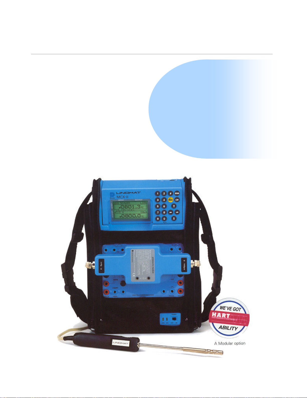
MCX II
MCX II
Portable documenting calibrator
n Reduces instrumentation maintenance costs
n Over 90 Input/Output ranges: Pressure,
Temperature, Electrical and Frequency
n Interchangeable pressure modules -14.7 to 5000 psi
n HART® module for Smart transmitters
n Memory card for procedure and data transfer
cd
n Eliminates field calibration errors
USMCX II -PDS-A132 09/00
1
Page 2

MCX II
Portable documenting calibrator
A CALIBRATION WORKSHOP IN A
SINGLE INSTRUMENT
The Druck MCX II portable documenting calibrator is the most comprehensive field
calibration tool available. It is the culmination of many years combined field experience
with the Druck and Unomat series of portable pressure, temperature and electrical
calibrators.
Designed for field use, this rugged, self-contained, battery powered package simulates and
reads RTD’s, thermocouples and resistance, as well as sourcing and reading milliamps,
millivolts, volts and frequency. With interchangeable single and dual sensor pressure modules
over 90 input and output ranges are available.
The MCX II saves time and money with the calibration, maintenance and commissioning of
instrumentation for process plants, production lines, utility processing and distribution by:
n Reducing the burden imposed by quality systems such as ISO 9000.
n Reducing calibration, maintenance and commissioning time.
n Reducing documentation time and errors.
n Replacing several standard test instruments.
n Reducing test instrument calibration costs.
n Minimising down time and maximising efficient field usage.
For example, a typical thermocouple transmitter calibration can take one hour using a mV
source, look-up tables and a milliammeter. In just five minutes the MCX II can make an
automatic calibration and document the results while virtually eliminating human errors.
A PCMCIA memory card provides data storage and gives total flexibility to suit different
working practices. By simply exchanging PCMCIA cards, the MCX II can remain permanently
in the field and when compared to serial data transfer methods this can save one to two hours
a day. With a single item to calibrate the cost of re-calibration is reduced and the
inconvenience of down time is minimized.
HART® communicator for SMART transmitters
The HART® communicator allows digital field adjustment of smart transmitters. Typical
adjustments to sensor and analogue trims can take up to 40 minutes using conventional test
equipment and a hand held communicator. With a single MCX II this time can be reduced to
less than 10 minutes, including a fully documented calibration.
High precision and multi-functional
Typical accuracy: 0.01% Rdg +/-0.003% FS for mA measurement
Input: mA, mV, volts, T/C’s, RTD’s, pressure, ohms,
frequency and switch state.
Output: mA, mV, volts, T/C’s, RTD’s, ohms, and frequency.
Pressure modules: Interchangeable single and dual ranges from -14.7 to
HART® communicator: HART® digital communicator for SMART transmitters.
C/J compensation: Internal, external and manual.
Loop Power: Dual 24 Vdc.
Temperature probe: 1/5 DIN accuracy P100 probe.
Data storage: 1 Mbyte PCMCIA card.
Data transfer: PCMCIA card or RS 232 interface.
PC software: Linkpak-W and Intecal-W.
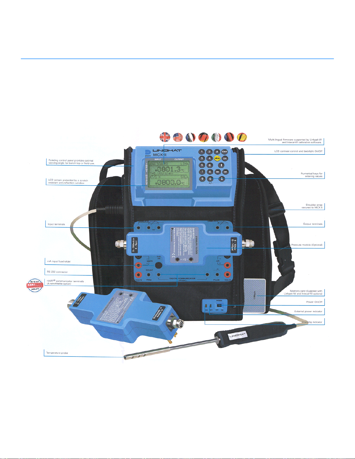
Easy to use
The multi-lingual user interface is an easy to use Input/Output menu with dual parameter
readout. The Input and Output connectors are standard 4mm gold plated sockets which are
separated and clearly labelled. The rugged impact resistant enclosure is surrounded by a
durable protective carry case which allows access to all the instrument features and provides
convenient pockets for storing test leads and accessories. Whether the MCX II is horizontal or
vertical the rotatable display provides the optimal viewing angle. On the bench, test leads and
pressure modules connect to the front face. In the field, with the MCX II held vertically by the
wide neck strap, the connections are made to the rear face. With safety a major design
concern, these features reduce the possibility of dropping equipment as the operators hands
are kept free.
0.05% Rdg for pressure measurement,
5000 psi including gauge, absolute and differential.
USMCX II -PDS-A132 09/00
2
Page 3
USMCX II -PDS-A132 09/00
3
Page 4

MCX II
Applications
MULTI-FUNCTION PORTABLE CALIBRATOR
The MCX II has been designed for ease of use while meeting a wide
range of application needs including calibration, maintenance and
commissioning. The dual parameter display shows the input and output
values in large clear digits with all applicable information such as the
units of measurement and range. Using the rotating display, the rear
face electrical connectors and wide neck strap, the instrument can be
safely worn around the neck or fastened to a suitable pipe or valve.
This leaves the operators hands free at all times and prevents
dangerous dropages.
Some of the capabilities include:
n Input/output mA
n Input/simulate 12 types of T/C
n Input/simulate 9 types of RTD
n Input/output frequency and pulses
n Simulate transmitter input and measure transmitter output
n Input/output mV/V
n Input/output resistance
n Measure pressure: -14.7 to 5000 psi
n Test switches: captures values on contact change
n Trim smart HART transmitters
Easy to operate
The easy to operate menu driven software enables the MCX II to be
set-up very quickly. Simply scroll through the input and output menus
to select the required parameters.
Operating and connection errors such as loop resistance mismatch and
cold junction temperature sensor absence are reported.
The KEYSTROKING memory enables instant recall of previously stored
user tests.
cd
TEMPERATURE TRANSMITTER SIMULATION AND CALIBRATION
Direct connection of thermocouple compensation wires eliminates the need for
special connectors. The cold junction temperature is continuously monitored and
compensated for, even under the transient conditions experienced by a field
calibrator. This is the most reliable and accurate cold junction compensation
method found in a portable field calibrator.
In calibration mode the MCX II simulates the temperature signal to the transmitter
and simultaneously measures the output. The display shows both the mV output
and mA input scaled in °C or °F for easy comparison. The error between the two
values is displayed as a percentage of a span or reading. The PASS/FAIL status
is also displayed when running pre-defined procedures from the calibration
software Linkpak-W or Intecal-W. For convenience, dual 24 Vdc loop power
supplies are available.
Pressure and RTD calibration modes operate in a similar way. The connection of
2, 3 and 4 wire RTD’s is detected automatically, a feature unique to Druck
portable field calibrators.
USMCX II -PDS-A132 09/00
4
Page 5
cd
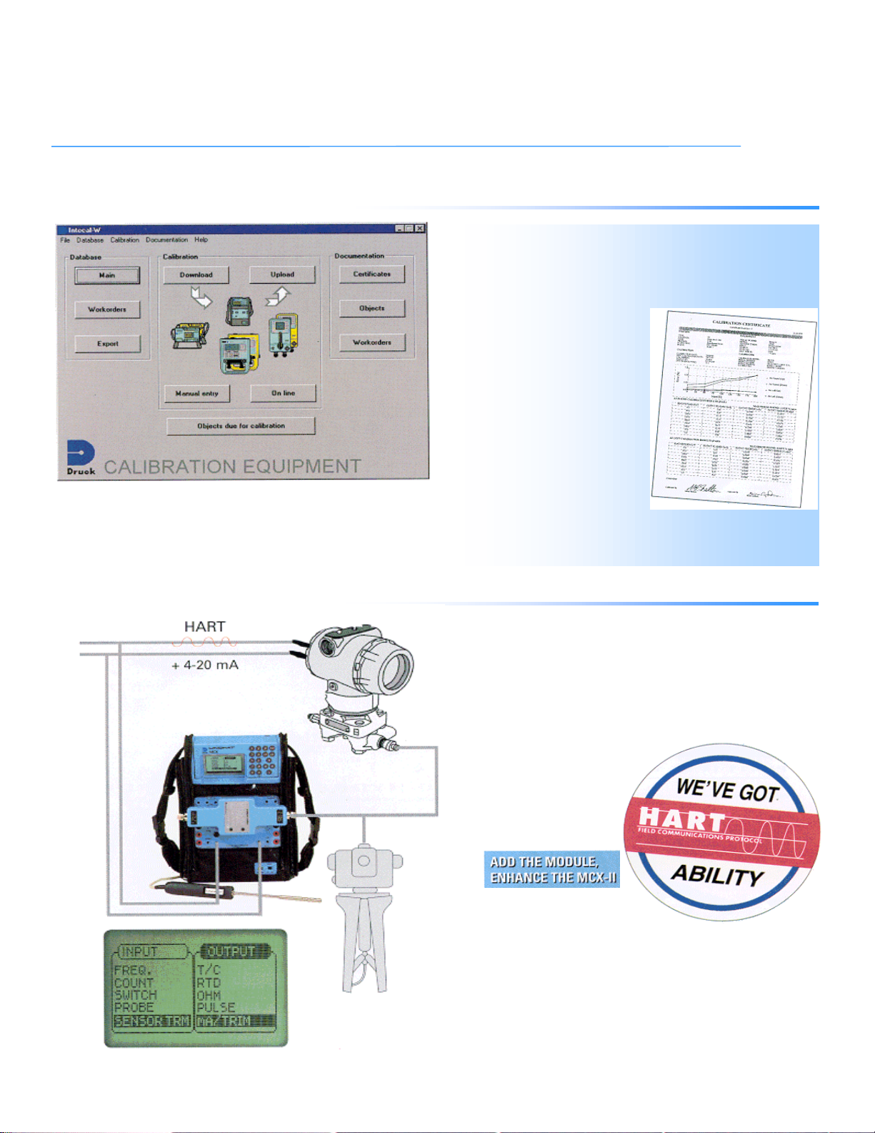
CALIBRATION TO ISO 9000 AND SIMILAR APPROVALS
Linkpak-W and Intecal-W Calibration Software reduce the burden imposed by
quality systems, saving both time and money. Documentation quality is improved
by the elimination of data errors and the production of clear traceable calibration
records.
An instrument database defines the
calibration procedures and interval.
Instruments can be batched into
work orders representing, for
example, the work for one
technician in one day. These work
orders are downloaded to the
PCMCIA card for use with any
MCX II available in the field. The
calibration routines are performed
automatically and the results are
stored on the PCMCIA card. The
card is then returned to the PC,
independently of the MCX II, for
the documentation to be
completed.
Linkpak-W and Intecal-W have
export facilities for moving data
into other applications and
databases. Many third party
packages are now directly compatible
with the MCX II and other Druck calibrators.
CALIBRATING SMART HART TRANSMITTERS
The optional HART digital communicator when installed in the MCX II replaces the
need for a separate hand held communicator. It can greatly reduce HART
transmitter maintenance times and provides a high level of protection by preventing
changes in the field to the device identity, range, set-up and characterization. The
MCX II communicates digitally with the HART transmitter to establish device
parameters such as tag number, serial number and range. It acts as an electronic
‘screwdriver’ for adjusting both the sensor and mA trims. This operation is essential
if the correct performance of HART
transmitters is to be maintained.
The HART digital communicator is
compatible with a number of
smart HART transmitters.
Please contact your nearest
sales office for an up to
date list.
HART is a registered trademark of the HART Communications Foundation
USMCX II -PDS-A132 09/00
5
Page 6
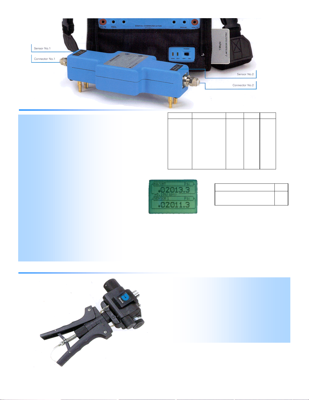
MCX II PRESSURE MODULES
0 -
500 psi
±0.05% rdg. ±0.01% fs.
0 -
1750 psi
±0.05% rdg. ±0.01% fs.
High Accuracy
Single or dual range pressure modules can be
configured to provide over 400 combinations for gauge, absolute and
differential pressure measurement. With
typical accuracies better than 0.05% of reading ±0.01%
F.S. these expand the MCX II capabilities even further. Modern
pressure instrumentation can be easily
maintained, even smart pressure transmitters when
using the optional HART® communicator.
In pressure calibration mode the MCX II displays the
applied pressure and also the corresponding mA output (converted into
pressure for easy comparison).
Additionally, the error between these values is also
shown as a percentage of span or reading and when
used with Linkpak-W or Intecal-W the PASS/FAIL status
is also reported.
Interchangeability
The pressure modules fit directly onto the instrument
front or rear casing suitable for benchtop or field
operation and when not in use simply attach to the
MCX II carry case.
Advanced Druck sensors and their performance
characteristics are stored inside each compact pressure module,
enabling convenient use on any MCX II without
re-calibration.
When used with Linkpak-W or Intecal-W calibration procedures, any
module range not conforming to the procedure is reported. For
traceability, the serial
numbers of both the pressure module and MCX II are recorded together
with the calibration results.
Pressure range Accuracy
-14.7 - 0 psi ±0.1% FS 0.00015 psi #612
0 - 5 psi ±0.0015 psi ± 1 digit 0.00005 psi #611 #611A
0 - 20 psi ±0.05% rdg. ±0.01% fs. 0.0002 psi #600 #600A
0 - 30 psi ±0.05% rdg. ±0.01% fs. 0.0003 psi #601 #601A
0 - 50 psi ±0.05% rdg. ±0.01% fs. 0.001 psi #620 #620A
0 - 100 psi ±0.05% rdg. ±0.01% fs. 0.01 psi #602 #602A
0 - 150 psi ±0.05% rdg. ±0.01% fs. 0.01 psi #603 #603A
0 - 200 psi ±0.05% rdg. ±0.01% fs. 0.01 psi #621 #621A
0 - 300 psi ±0.05% rdg. ±0.01% fs. 0.01 psi #607 #607A
0 - 600 psi ±0.05% rdg. ±0.01% fs. 0.01 psi #604 #604A
0 - 1000 psi ±0.05% rdg. ±0.01% fs. 0.1 psi #605 #605A
0 - 2000 psi ±0.05% rdg. ±0.01% fs. 0.1 psi #623
0 - 3000 psi ±0.05% rdg. ±0.01% fs. 0.1 psi #624
0 - 5000 psi ±0.05% rdg. ±0.01% fs. 0.1 psi #625
Measurement
resolution
0.01 psi #622 #622A
0.1 psi #606
Sensor P/N
(Gauge)
Sensor P/N
(Absolute)
Pressure connection P/N
1/8” NPTF
316L, Hastelloy and viton.
Max. 10,000 psi
Ordering Information
MCX-PM (Pressure Module) includes; operating manual, calibration traceability
certificate. A calibration report/certificate with data is optional.
Please state ordering code as follows:
MCX - PM - Sensor1 - Sensor2
Note: Position 1 is lefthand side
616
PV411 (4 IN 1) PNEUMATIC AND HYDRAULIC HAND PUMP
The revolutionary PV 411 (4 In 1) multi-function pressure generator is a
remarkable hand pump for generating vacuum, gas and hydraulic pressures. A
single PV 411 replaces four conventional hand pumps and sets new standards
of performance in each of the following disciplines:
Vacuum: 28.5 inHg
Low pressure (gas): in H2O range fine control
Medium pressure (gas): 600 psi
Hign pressure (hydraulic): 10,000 psi
The PV 411 is the ideal pressure source for calibrations and tests using MCX II
pressure modules. For more information please refer to the PV 411 data sheet.
USMCX II -PDS-A132 09/00
6
Page 7

MCX II
Standard Specification
cd
MEASURE
Input Range 1 Year Accuracy Resolution Remarks
MV
(autoranging)
V
(autoranging)
mA
Ohms
(autoranging)
Frequency
(autoranging)
Counts/minute
Totalizing counter
Accuracy (% of reading + % of range + 1 LSD)
0 … 100 mV
100 … 600 mV
0 … 6 V
6 … 60 V
0 … 52 mA
0 … 400 Ohm
400 … 2000 Ohm
0 … 655 Hz
655 … 1310 Hz
1310 … 10,000 Hz
0 … 6 x10
0 … 10
0 … 10
5
7
–1
8
- 1
0.004% + 0.004%
0.005% + 0.005%
0.009% + 0.003%
0.009% + 0.003%
0.010% + 0.003%
0.010% + 0.005%
0.010% + 0.005%
0.01 Hz
0.1 Hz
1 Hz
1 c/min.
1 c/hour
infinite
0.001
0.01
0.0001
0.001
0.001
0.01
0.1
0.01
0.1
1
1
1
1
R – input > 20 M Ohm
R – input > 1 M Ohm
R – input > 2.5 Ohm fused
at 0.9 mA excitation
at 0.9 mA excitation
R – input > 300 k Ohm
R – input > 300 k Ohm
R – input > 300 k Ohm
R – input > 300 k Ohm
R – input > 300 k Ohm
R – input > 300 k Ohm
SOURCE
Output Range 1 Year Accuracy Resolution Remarks
MV
-10 … 100 mV
V
0 … 12 V
MA
Ohms
Pulse
Frequency
pulses/min
pulses/hour
Accuracy (% of reading + % of range + 1 LSD)
0 … 24 mA
0 … 400 Ohm
0 … 2000 Ohm
0 … 108 –1
0 … 100 Hz
0 … 10,000 Hz
0 … 6000
0 … 99,999
0.003% + 0.004%
0.004% + 0.002%
0.012%
0.005% + 0.008%
0.010%
infinite
0.01 Hz
1 Hz
1 p/min
36 p/hour
0.001
0.0001
0.001
0.01
0.1
1
0.01
1
1
1
R – output < 0.2 Ohm
R – output < 0.2 Ohm
R – max 900 Ohm
at 1 mA excitation
at 1 mA excitation
0 … 24 V/ 34 mA max.
0 … 24 V/ 34 mA max.
0 … 24 V/ 34 mA max.
0 … 24 V/ 34 mA max.
0 … 24 V/ 34 mA max.
TEMPERATURE
RTD Range 1 Year Accuracy Resolution
Pt1000
Pt500
Pt200
Pt100
Pt50
D-100
Ni 100
Ni 120
Cu10
¬ = IEC 751, - = JIS 1604-1989, ® = DIN 43760, ¯ = MINCO 7, ° = MINCO 16-9
T/C Range 1 Year Accuracy Resolution
J
L
K
T
U
B
R
S
E
N
C
D
¬
¬
¬
¬
¬
®
¯
°
¬
¬
¬
¬
¬
¬
¬
¬
-200 … 400 °C
-200 … 850 °C
-200 … 850 °C
-200 … 850 °C
-200 … 850 °C
-200 … 649 °C
-60 … 250 °C
-80 … 260 °C
-200 … 260 °C
-210 ... 1200 °C
-200 ... 900 °C
-270 ... 1372 °C
-270 ... 400 °C
-200 ... 600 °C
50 ... 1820 °C
-50 ... 1769 °C
-50 ... 1769 °C
-270 ... 1000 °C
-270 ... 1300 °C
0 ... 2320 °C
0 ... 2495 °C
Measure
0.1 °C
0.1 °C
0.2 °C
0.15 °C
0.25 °C
0.15 °C
0.1 °C
0.1 °C
1.0 °C
Measure
0.1 °C
0.1 °C
0.1 °C
0.1 °C
0.1 °C
0.4 °C
0.5 °C
0.5 °C
0.1 °C
0.1 °C
0.2 °C
0.2 °C
Source
0.1 °C
0.1 °C
0.3 °C
0.12 °C
0.2 °C
0.12 °C
0.1 °C
0.1 °C
1.5 °C
Source
0.1 °C
0.1 °C
0.1 °C
0.1 °C
0.1 °C
0.4 °C
0.5 °C
0.5 °C
0.1 °C
0.1 °C
0.2 °C
0.2 °C
¬= IEC 584, - = DIN 43710
Best case, Mid Range accuracies +1 LSD
Note: Internal cold junction compensation error +/- 0.2°C (± 0.4°F)
0.1 °C
0.1 °C
0.1 °C
0.03 °C
0.06 °C
0.03 °C
0.1 °C
0.1 °C
0.3 °C
0.1 °C
0.1 °C
0.1 °C
0.1 °C
0.1 °C
0.1 °C
0.1 °C
0.1 °C
0.1 °C
0.1 °C
0.1 °C
0.1 °C
SPECIAL FEATURES
Temperature units
°C or °F
Temperature scales
IPTS 68 or ITS 90 selectable
Pressure units
10 units
Step
10 programmable, 10%, 20%, 25%. Manual step or adjustable timer
Ramp
Fully programmable travel time (up/down and dwell)
Scaling
5 digits and sign on all electrical ranges
Temperature transmitter calibration
Both input and output readings in temperature units
Calibration feature extended for all output functions
Temperature transmitter simulation
mA output reads in temperature units
Loop power
Dual 24Vdc Loop power supplies
Signal converter
Converts any input into any output, fully isolated
Keystroking
Storage for 10 user defined test configurations
Switch test
Display freezes on open and close action
Data storage
1 Mbyte of data storage - see option (A3)
Computer interface
RS 232 and PCMCIA card - see option (A3)
PCMCIA station
PCMCIA card type 1 or 2 - activated by option (A3)
Language
English, French, German, Italian, Portuguese and Spanish
Power management
Auto backlight OFF, battery low indicator
DISPLAY
Panel
2.6 in x 1.6 in Graphic LCD with backlight
Readout
Typically 5 readings/ second
ENVIRONMENTAL
Calibration reference
22°C +/- 1°C (72°F +/-2°F), R.H. 45% +/- 15%
Accuracies
Accuracies true for 17°C to 27°C (60°F to 80°F). Outside these limits add 0.0005%/°C
(0.00025%°F) typically
Reference for all electrical parameters only.
Temperature
Operation: -10°C to 50°C (15°F to 120°F)
Humidity:
0 - 90% non condensing
Sealing
Generally to NEMA 12 (IP53)
Conformity
EN50081-1, EN50082-1, CE Marked
Physical
1.1 lb, 10.5 in x 6.3 in x 2.0/3.2 in
Power supply
6 x 1.5 V alkaline “C” cells 6 x 1.2 V Ni-Cad “C” cells
USMCX II -PDS-A132 09/00
7
Page 8

MCX II
Options and related products
cd
OPTIONS
(A1)
(A2)
(A3)
(B)
(C)
(D)
(E)
Linkpak-W calibration software (P/N LPDPI)
Developed to help meet the growing demand on industry to comply with
quality systems and calibration documentation. Test procedures are
created in a Windows based application and devices due for calibration
are reported and grouped into work orders for transfer to
the DPI 605,
DPI 615, TRX-II and the
MCX II. Calibration results,
including files from the DPI
610, are uploaded to the PC
via the RS 232 interface (or
PCMCIA card) for analysis
and to print calibration
certificates.
Visit www.druckinc.com for Linkpak-W demonstration
Intecal-W calibration database software (P/N ICDPI)
Builds on the basic concept of Linkpak-W supporting both portable
field calibrators and on-line workshop calibrators; manual data entry
is also a key feature for recording data. Intecal-W is a simplified
calibration management software which enables a high productivity
of calibration scheduling/work and documentation. Device
information, calibration procedures and results are stored in an
instrument database.
Multiple databases can be
created for organising client
accounts, processes or
areas. Extensive
management features
provided include a database
search engine, time based
calibration due queries and
standard reports.
Visit www.druckinc.com for Intecal-W demonstration
Documenting release key (P/N 405-A014)
A PCMCIA card which adds full documenting capabilities to the MCX II
with 1 Mbyte of memory for procedures and results. Each MCX II requires
a key to work with PC based software. RS 232 cable provided.
Interchangeable pressure modules (P/N (refer to table))
Single or dual range pressure modules with sensor ranges from -14.7 to
5000 psi including gauge and absolute versions.
HART® digital communicator (P/N 405-A003)
For full calibration and adjustment of HART transmitters without a
separate digital communicator. It can also be retrofitted by the user.
High accuracy temperature probe (P/N 191-A012)
A hand held PT100 1/5 DIN reference temperature probe for measuring
ambient air temperatures during calibrations or at thermocouple remote
cold junctions. Cable length 4.5 feet.
Battery charger/eliminator (P/N 191-A005 110V)
This 110V adapter can either power the MCX II from line voltage or
recharge Ni-cad batteries (batteries not supplied). The MCX II can be
recharged and operated simultaneously. Refer to factory for 220V
version.
ACCESSORIES
Carrying case, test leads, user guide, hand book, batteries and calibration certificate of
conformance supplied as standard (NIST calibration report with data is optional).
CALIBRATION STANDARDS
CALIBRATION STANDARDS
Calibrators manufactured by Druck are calibrated against precision calibration
equipment traceable to National Institue of Standards and Technology (NIST).
RELATED PRODUCTS
RELATED PRODUCTS
Portable field calibrators
Druck manufacture a wide range of portable pressure, temperature and electrical field
calibrators. A selection of these are shown below.
Laboratory and workshop instruments
Druck also manufacture a wide range of pressure indicators and controllers. This
includes Pressurements industrial deadweight testers and Ruska precision controllers
and primary standard piston gauges.
Pressure transducers and transmitters
Druck instruments complement an extensive range of pressure transducers and
transmitters, utilized in a variety of aerospace, automotive, depth level and process
applications.
Please refer to manufacturer for further information on related products.
ORDERING INFORMATION
Please state the following (where applicable):
1. Model number MCX II.
2. Options, including part numbers. For MCX II pressure modules please
refer to the ordering code tables and state the pressure range/s required.
For options (A1) or (A2) please order
option (A3) for each MCX II.
Note: options should be ordered as separate line items.
Continuing development sometimes necessitates specification changes without
notice.
Druck is an ISO 9001
registered company
cd
Druck Incorporated
4 Dunham Drive
New Fairfield, CT 06812
Tel: (203)-746-0400
Fax: (203)-746-2494
E-Mail: usa.sales@druck.com
Internet: www.druckinc.com
Representative:
USMCX II -PDS-A132 09/00
8
 Loading...