

Page 1

PRESSURE MEASUREMENT
DPI 610
PORTABLE PRESSURE
CALIBRATOR/INDICATOR
CALIBRATION INSTRUCTIONS
K235
Issue Date: 12th March, 1999
© Druck Limited 1999
This document is the property of Druck Limited and may not be copied or otherwise reproduced, communicated in any way to
third parties, nor stored in any Data Processing System without the express written authority of Druck Limited.
Druck Limited, Fir Tree Lane, Groby, Leicester LE6 0FH, England. Tel: (0116) 231 7100 Fax: (0116) 231 7103
K235 Issue 2
Page 2
Calibration Procedures
DPI 610
DPI 610
PORTABLE PRESSURE CALIBRATOR/INDICATOR
CALIBRATION INSTRUCTIONS
K235
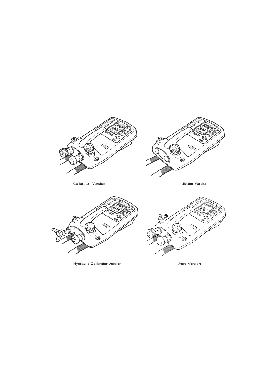
DPI 610 Instrument Versions
© Druck Ltd. 1998
This document is the property of Druck Limited and may not, either in part or whole, be
copied or otherwise reproduced, communicated in any way to third parties nor stored in any
Data Processing system, without the express written authority of Druck Limited.
1
K235 Issue No. 2
Page 3
DPI 610 Calibration Procedures
Calibrator Version
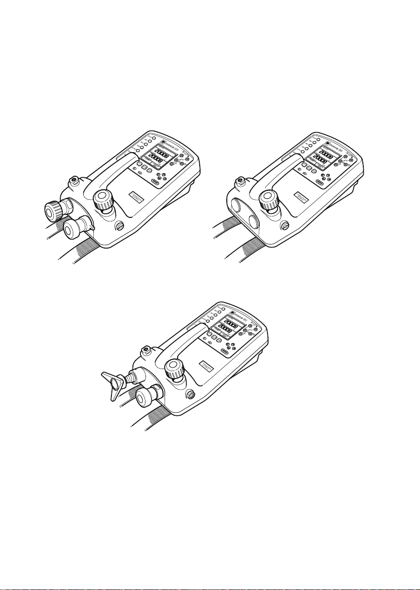
DPI 610 IS Intrinsically Safe Instrument Versions
K235 Issue No. 2
2
Page 4

Calibration Procedures
DPI 610
Contents
General...................................................................................................5
Introduction.............................................................................................6
General Procedures..........................................................................6
Calibration Protection .......................................................................6
Calibration Check .............................................................................7
Calibration Adjustment......................................................................7
Test Equipment.................................................................................7
Using The Calibration Men u.............................................................7
Change Calibration PIN Number ............................................................8
Calibrate Internal Ranges .......................................................................9
Pressure ...........................................................................................9
Voltage Input Range ( 5 Volts)........................................................10
Voltage Input Range (30 Volts).......................................................12
Voltage Input Range (50 Volts).......................................................14
Current Input Range (55 mA)..........................................................16
Current Output Range (24 mA).......................................................18
Ambient Temperature Channel .......................................................21
Calibrate External Ranges....................................................................22
Pressure .........................................................................................22
Service .................................................................................................24
Approved Service Agents ..............................................................24
Returned Goods Procedure...........................................................25
Safety Precautions (Returned Goods) ......................................25
Tables
Table 1 - Internal/External Pressure Transducer V erification .................26
Table 2 - Voltage Input Calibration Tolerances (Standard models) ........27
Table 3 - Current Input Calibration Tolerances ......................................28
Table 4 - Current output Calibration Tolerances ....................................29
Table 5 - Voltage Input Calibration Tolerances (IS models only) ............27
3
K235 Issue No. 2
Page 5

DPI 610 Calibration Procedures
INTRINSIC SAFETY CONDITIONS OF USE
This handbook covers the calibration instructions for both standard
instruments and intrinsically safe models. Intrinsically safe models are
designed to be intrinsically safe when operated in accordance with the
BASEEF A Certification document and schedule which is supplied.
BASEEFA Certificate of Conformity No. Ex 99E2002X
BASEEF A being an Approv ed Certification Body, in accordance with
Article 14 of the Council Directive of th European Communities of 18th
December, 1975 (76/117/EEC) certifies that the apparatus has been
found to comply with harmonised European Standards:
EN 50014: 1992
EN 50020: 1994
and has successfully met the examination and test requirements
recorded in confidential report Number
98(C)0818 (ERA Report Ref.3627/856), dated January, 1999
NOTE: For intrinsically safe models, attention is dra wn to P ages 4/5
of the Certificate of conformity.
INTRINSICALLY SAFE MODELS SHOULD BE CALIBRATED IN A SAFE AREA
K235 Issue No. 2
4
Page 6
Calibration Procedures
DPI 610
General
This publication covers the calibration procedures f or DPI 610 Portable Pressure Calibrator/
Indicators and should be read in conjunction with Druck Publications K213 and K239.
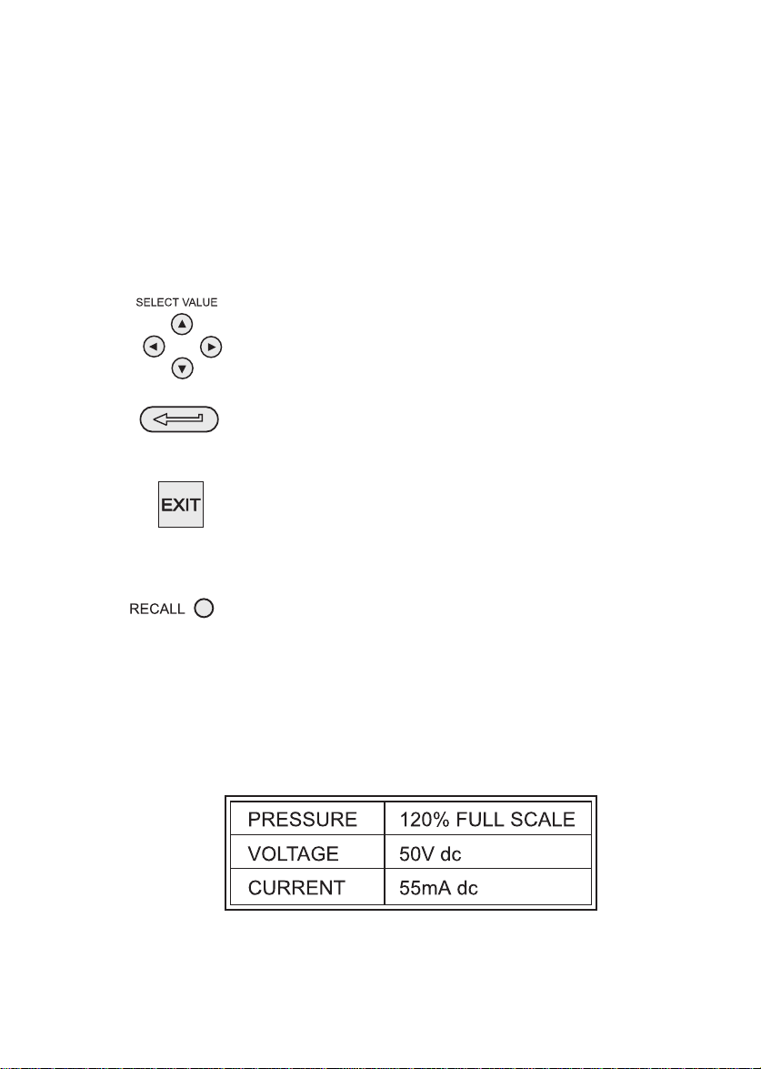
The following key symbols are used in the procedure diagrams which follow and are
repeated here (from K213), to allow this supplement to stand alone. P ages 1 to 7 of K213
and K239 detail the operator controls and general information which is relevant to all
options of the DPI 610 Instrument.
Shaded cursor keys indicate that a combination of these four ke ys,
Up, Down, Left and Right should be used to (e.g.) enter an alpha
numeric value or to select a function.
Indicates the ENTER key. Used to confirm an operation or a
selection. Shading indicates key operation.
Exit key, used to clear current menu selection and return to next
menu level abov e current lev el. Used as an escape k ey from current
operation. Shading indicates key operation.
Hardkey (total 7). Legend beside key symbol indicates function.
Shading indicates key operation.
Maximum Instrument Ratings
The following table shows the maximum measurement ratings of the standard instr ument
which should not be exceeded. Pressure overrange (120% of FS) is indicated by the
pressure display flashing. Voltage or current overrange, causes either the voltage or current
display to flash.
,[30V dc (IS)]
Note:
For the DPI 610 AERO version, when the AERO task is selected,the display
flashes if the voltage or current input overranges by 110% of the above maximum
values. The pressure display flashes at altitudes below -3000 ft and above
50,000 ft or at airspeeds greater than 600 kts,depending upon the mode selected.
5
K235 Issue No. 2
Page 7

DPI 610 Calibration Procedures
Introduction
The instrument is supplied by the manufacturer, complete with calibration certificate(s).
The re-calibration interval will depend on the total measurement uncertainty which is
acceptable for a particular application. In order that the instrument remains within the
quoted accuracy, it is suggested that it’s calibration be checked at 90 day inter vals.
The DPI 610 is a very precise measuring instrument and the test equipment and conditions
of test must be suitable for the type of work. The use of a Class A compensated deadweight
tester is essential. The tests should be carried out in a controlled environment by a
competent, trained person.
If, when the accuracy of the instrument is checked, it is f ound to fall outside the specification,
calibration adjustment can be undertaken to compensate errors.
The manufacturer offers a comprehensive and, if required, NAMAS accredited calibration
service.
General Procedures
The following general hints are provided as a guide to calibration procedures.
Do
Use high quality
time before calibration (minimum 1 hour).
Conduct the calibration in a temperature and preferably, humidity controlled environment.
Recommended temperature is 21°C, ±2°C.
Use deadweight testers carefully and away from draughts.
Review and become familiar with the whole calibration procedure before commencing the
calibration process.
Ensure that the instrument is NOT set to BASIC mode. The Instrument’ s calibration routines
are not accessible from this mode. If necessary, use the TASK key to select another mode
(e.g.) ADVANCED.
Repeatable and Linear
pressure sources and allow adequate stabilisation
Calibration Protection
In order to protect against accidental loss,the calibration of this instrument is
protected by a PIN number. Initially, this PIN number is set to 4321. To prevent
unauthorised access to the calibration routines, it is recommended that this PIN
number should be changed at the earliest opportunity(refer to Page 8).
K235 Issue No. 2
6
Page 8
Calibration Procedures
DPI 610
Calibration Check
At the chosen interval, the instrument readings should be compared with a known standard.
Any deviations between the instrument and the standard should be noted, taking due
account of the traceability (accuracy to a National Standard). If these deviations exceed
the published tolerance, or any other suitable chosen performance standard, then the
user may wish to carry out a calibration adjustment.
It is recommended that measurements be checked at 0, 20, 40, 60, 80 and 100% of full
scale on an ascending and descending run. Refer to Tables 1 to 4, pages 27 to 30, for
details of test inputs and tolerances.
Calibration Adjustment
If the instrument is operating correctly, only zero and full scale calibration will vary. Any
excessive non-linearity or temperature effects indicate a fault. In these circumstances,the
instrument should be returned to a qualified service agent (refer to pages 22 and 23).
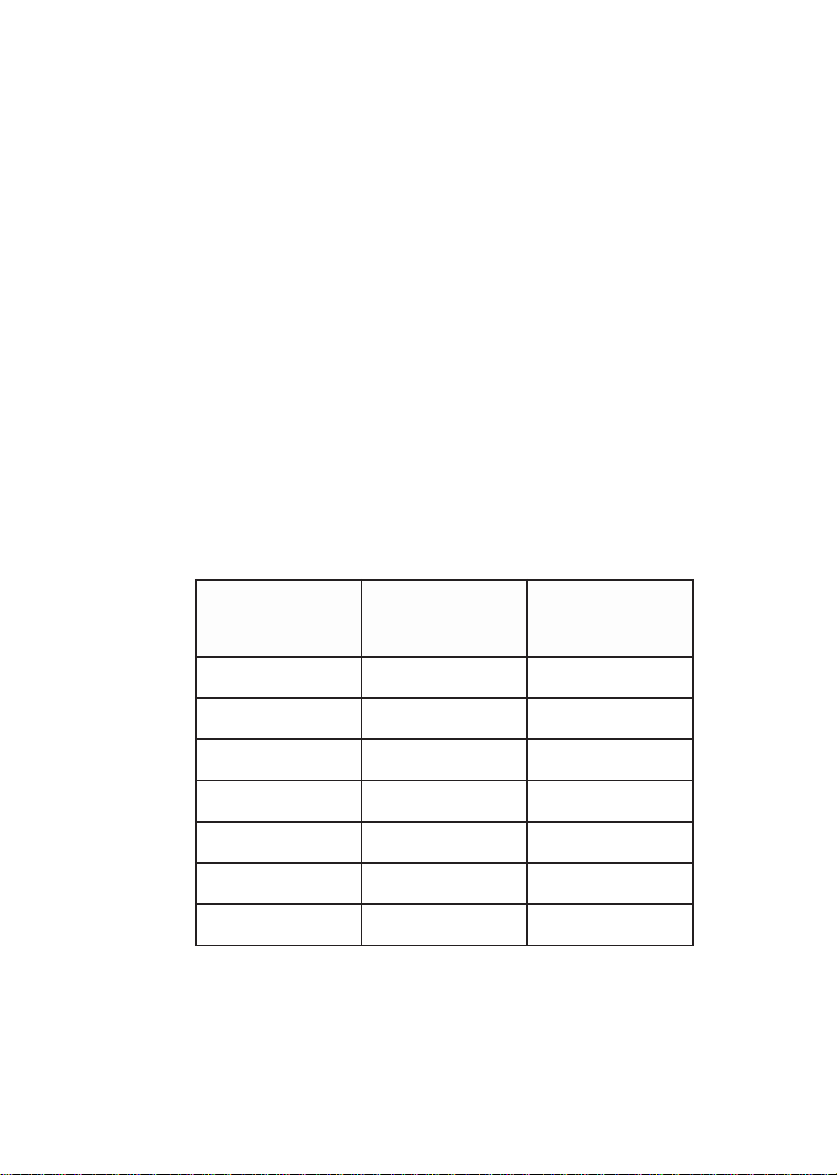
Test Equipment
The following laboratory standard test equipment will be required for the calibration
procedures:-
tnemurtsnI
egnaR
noitarbilaC
tnempiuqE
noitarbilaC
ytniatrecnU
ycaruccA
tupnIV5
tupnIV05
tupnIAm55
tuptuOAm42
pmeTtneibmA
± mpp03 ± tigid1 ± mpp01 ± 5 mV
)sepyTSI(tupnIV03
± mpp54 ± tigid1 ± mpp11 ± 011 mV
± mpp54 ± tigid1 ± mpp11 ± 011 mV
± mpp051 ± stigid4 ± mpp001 ± An1
± mpp051 ± stigid4 ± mpp061 ± An1
± 2.0 °C ± 1.0 °C ± tigid1
txE/tnIerusserPthgiewdaeDAssalC%520.0<
Using the Calibration Menu
The calibration routines are selected from the Setup menu as detailed on page 8. The
calibration routines are not accessible whilst the instrumement is in BASIC mode. If
necessary therefore,use the TASK key to select another mode (e.g.) ADVANCED before
attempting to access the CALIBRATION mode.
7
K235 Issue No. 2
Page 9
DPI 610 Calibration Procedures
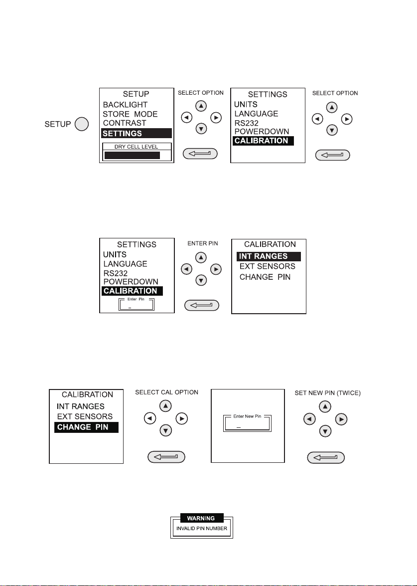
To enter the CALIBRATION mode, press SETUP and select CALIBRATE from the menu
as shown below.
Use a combination of the cursor keys to enter the PIN number (Initially set to 4321) as
shown below. The Up and Dow n keys enter numer als (0 to 9) or (9 to 0) respectively and the
right and left keys shift number position. If the Enter pin prompt disappears before the first
digit is entered, press ENTER to re-display.
Change Calibration PIN Number
The Calibration PIN number is changed from the Calibration Menu. Use the cursor keys to
select CHANGE PIN and proceed as follows.
Note that the new PIN number requires to be entered twice, the second entry being used to
verify the change. If the second PIN number entry differs from the first, the PIN number is
not changed and the following error message is displayed.
K235 Issue No. 2
8
Page 10
Calibration Procedures
DPI 610
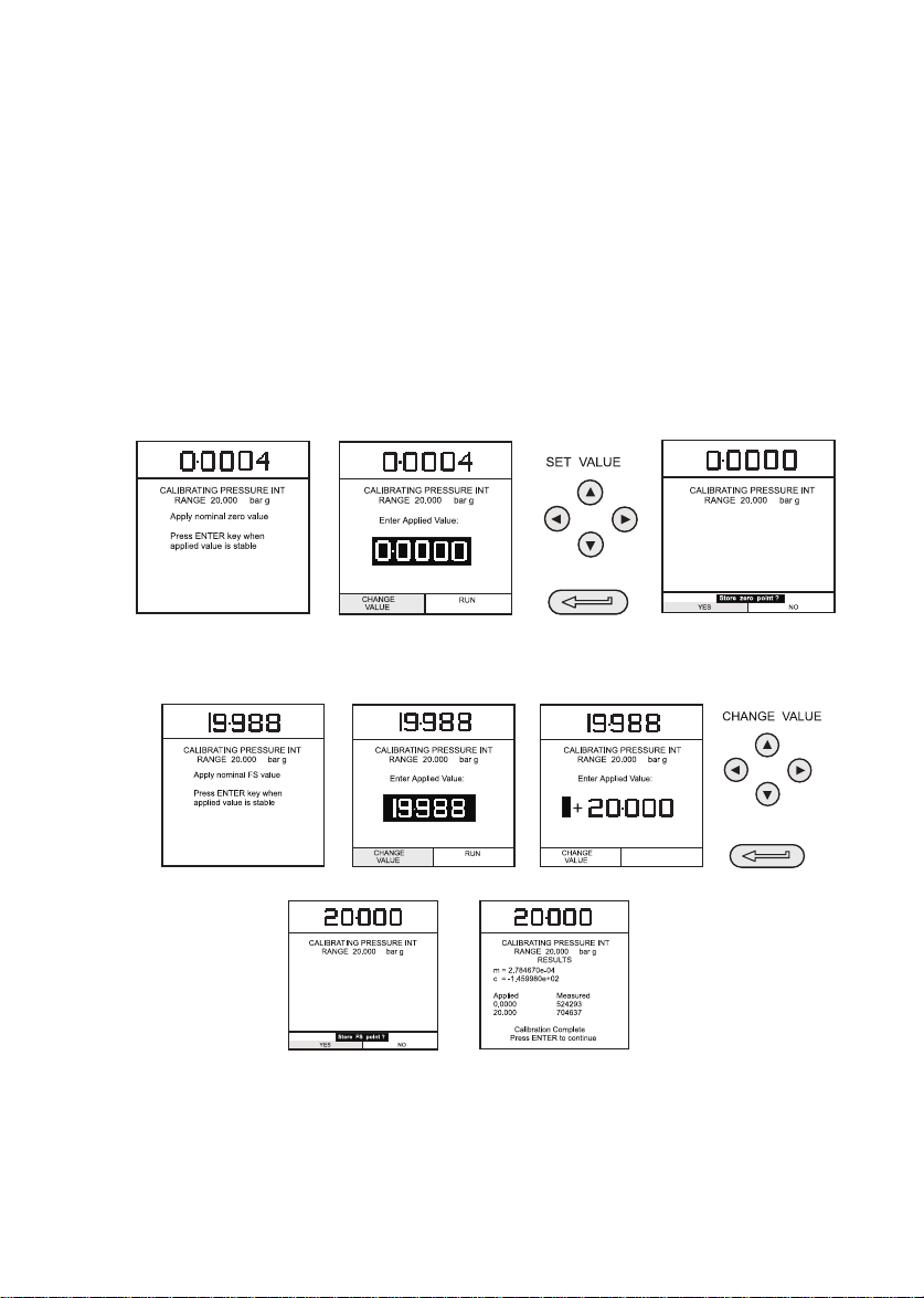
Calibrate Internal Ranges
Pressure
The following procedure should be adopted for calibrating the inter nal pressure range.
Note: If calibrating the hydraulic calibrator version, the calibrator must first be primed
as detailed on pages 39 to 42 of K213, pages 37 to 41 of K239.
(1) Connect the outlet port of the instrument to a pressure standard.
(2) Allow the instrument’s temperature to stabilise for a minimum of 1 hour.
(3) Switch the instrument on, enter CALIBRATION mode and select INT RANGES
from the CALIBRATION menu as shown on Page 8 and then PRESSURE INT.
(4) Apply zero pressure and store the zero point as shown below (e.g.),
(5) Close the vent valve, apply full scale pressure and store the full scale (FS)
point as shown below (e.g.),
(6) Press the ENTER key to accept the calibration. Press the EXIT key four times
to quit the CALIBRATION and SETUP modes.
(7) Check calibration by applying test pressures detailed in Table 1, Page 27.
9
K235 Issue No. 2
Page 11

DPI 610 Calibration Procedures
Voltage Input Range (5 Volts)
The following procedure should be adopted for calibrating the internal 5 Volt range.
(1) Switch the instrument on, enter CALIBRATION mode and select INT RANGES
from the CALIBRATION MENU as shown on Page 8.
(2) Select 5V range for calibration as shown below.
(3) Link the voltage input terminals with a short lead and enter the zero point as
shown below (e.g.),
(4) Remove the shorting link from the voltmeter terminals, connect the Vin terminals
of the instrument to a variable voltage source and connect a digital voltmeter
across the source as shown below.
max 30V
+
Cal V
-
DVM
Vin
mA Sink
mA in
55mA
max
Standard Version IS Version
K235 Issue No. 2
10
Page 12

Calibration Procedures
(5) Set the variable supply voltage to 5V ± 0.1V and enter the measured Full Scale
voltage applied as shown below (e.g.),
(6) Press the ENTER key to accept the calibration. Press the EXIT key once to
return to the calibration menu or four times to quit the CALIBRATION and SETUP
modes.
DPI 610
(7) Verify the instrument calibration by applying the test voltages given inTable 2
to the voltmeter (after both voltage ranges have been calibrated).
(8) Disconnect the calibration/test setup.
11
K235 Issue No. 2
Page 13

DPI 610 Calibration Procedures
Voltage Input Range (30 Volts)
The following procedure, which applies only to IS models, should be adopted for
calibrating the internal 30 Volt range.
(1) Switch the instrument on, enter CALIBRATION mode and select INT RANGES
from the CALIBRATION MENU as shown on Page 8.
(2) Select 30V range for calibration as shown below.
CALIBRATION
PRESSURE INT
VOLTAGE IN
SELECT CAL OPTION
SELECT RANGE
5 VOLTS
30 VOLTS
SELECT CAL OPTION
CURRENT IN
CURRENT OUT
TEMPERATURE
(3) Link the voltage input terminals with a short lead and enter the zero point as shown
below (e.g.),
SET VALUE
CALIBRATING VOLTAGE
RANGE +/- 30V
Apply nominal zero value
Press ENTER key when
applied value is stable
CALIBRATING VOLTAGE
RANGE +/- 30V
Enter Applied Value:
CHANGE
VALUE
RUN
CALIBRATING VOLTAGE
RANGE +/- 30V
Store zero point ?
YES NO
(4) Remove the shorting linkfrom the voltmeter terminals, connect the Vin terminals
of the instrument to a variable voltage source and connect a digital voltmeter
across the source as shown below.
max 30V
+
K235 Issue No. 2
Cal V
DVM
Vin
-
mA Sink
mA in
55mA
max
12
Page 14

Calibration Procedures
DPI 610
(5) Set the variable supply voltage to 30V ± 0.1V and enter the measured Full Scale
voltage applied as shown below (e.g.),
SET VALUE
CALIBRATING VOLTAGE
RANGE +/- 30V
Apply nominal FS value
Press ENTER key when
applied value is stable
CALIBRATING VOLTAGE
RANGE +/- 30V
Enter Applied Value:
CALIBRATING VOLTAGE
RANGE +/- 30V
Enter Applied Value:
CHANGE
VALUE
CALIBRATING VOLTAGE
RANGE +/- 30V
Store FS point ?
YES NO
RUN
CALIBRATING VOLTAGE
RANGE +/- 30V
RESULTS
m = 1.395879e-05
c = -7.128004e+00
Applied Measured
0.0000 526380
29.984 873988
Calibration Complete
Press ENTER to continue
CHANGE
VALUE
RUN
(6) Press the ENTER key to accept the calibration. Press the EXIT key four times
to quit the CALIBRATION and SETUP modes.
(7) Verify the instrument calibration by applying the test voltages given inTable 5
to the voltmeter (after both voltage ranges have been calibrated).
Note: Max input 30V dc - APPLY ONLY THE TEST VOLTAGES SHOWN IN
THE SHADED AREA of Table 2.
(8) Disconnect the calibration/test setup.
13
K235 Issue No. 2
Page 15

DPI 610 Calibration Procedures
Voltage Input Range (50 Volts)
The following procedure should be adopted for calibrating the inter nal 50 Volt range,
(NOT ON IS MODELS).
(1) Switch the instrument on, enter CALIBRATION mode and select INT RANGES
from the CALIBRATION MENU as shown on Page 8.
(2) Select 50V range for calibration as shown below.
(3) Link the voltage input terminals with a short lead and enter the zero point as shown
below (e.g.),
(4) Remove the shorting linkfrom the voltmeter terminals, connect the Vin terminals
of the instrument to a variable voltage source and connect a digital voltmeter
across the source as shown below.
K235 Issue No. 2
14
Page 16

Calibration Procedures
(5) Set the variable supply voltage to 50V ± 0.1V and enter the measured Full Scale
voltage applied as shown below (e.g.),
(6) Press the ENTER key to accept the calibration. Press the EXIT key four times
to quit the CALIBRATION and SETUP modes.
DPI 610
(7) Verify the instrument calibration by applying the test voltages given inTable 2
to the voltmeter (after both voltage ranges have been calibrated).
(8) Disconnect the calibration/test setup.
15
K235 Issue No. 2
Page 17

DPI 610 Calibration Procedures
Current Input Range (55 mA)
The following procedure should be adopted for calibrating the current input range.
(1) Switch the instrument on, enter CALIBRATION mode and select INT RANGES
from the CALIBRATION MENU as shown on Page 8.
(2) Select CURRENT IN range for calibration as shown below.
(3) Open circuit the mA in terminals and enter the zero point as shown below.
(4) Connect the mA in terminals of the instrument to a variable current source and
connect a digital milliammeter in series wth the supply as shown below.
max 30V
Vin
IS Version
MILLIAMMETER
A
55mA
max
mA in
-
+
Vin
24V out
Standard Version
K235 Issue No. 2
MILLIAMMETER
max 50V
CAT II
55mA
mA in
mA Sink
Xmtr
mA out 10V out
A
-
max
+
16
Page 18

Calibration Procedures
(5) Set the input current to 55 ± 0.1mA and enter the measured Full Scale
input current as shown below (e.g.),
(6) Press the ENTER key to accept the calibration. Press the EXIT key four times
to quit the CALIBRATION and SETUP modes.
DPI 610
(7) Verify the instrument calibration by applying the test currents given inTable 3
to the milliammeter.
(8) Disconnect the calibration/test setup.
17
K235 Issue No. 2
Page 19

DPI 610 Calibration Procedures
Current Output Range (24 mA)
The following procedure should be adopted for calibrating the current output range.
(1) Switch the instrument on, enter CALIBRATION mode and select INT RANGES
from the CALIBRATION MENU as shown on Page 8.
(2) Select CURRENT OUT range for calibration as shown below.
(3) Connect a digital milliammeter to the instrument as shown below.
Note: On standard instruments, during a current out calibration routine, the
24V dc output is automatically turned on. On IS instruments an external
supply is required
max 50V
CAT II
max 30V
Vin
mA in
mA Sink
mA
mA out 10V out
24V out
Standard Version
K235 Issue No. 2
Xmtr
55mA
max
VOLTAGE
SOURCE
18
Vin
-
mA
mA Sink
mA in
55mA
max
+
IS Version
Page 20

Calibration Procedures
(4) Measure the 10% Full Scale output current and enter the value measured on the
external milliammeter as shown below (e.g.),
(5) Measure the 90% Full Scale output current and enter the value measured on the
external milliameter as shown below (e.g.),
DPI 610
(6) Press the ENTER key to accept the calibration. Press the EXIT key four times
to quit the CALIBRATION and SETUP modes.
(7) Verify the instrument’s output current calibration by setting up the loop test
currents as shown in Ta ble 4 and checking the set values against the
milliammeter standard. The procedure is as follows.
Note: Select the appropriate steps 8 to 10, depending upon model type.
19
K235 Issue No. 2
Page 21

DPI 610 Calibration Procedures
Standard Calibrator Versions Only
(8) Press the OUTPUT key, select mA VALUE and turn on the 24V supply as shown
below (e.g.),
(9) Set the loop output current to 5 mA as shown below and check that the output
current, measured on the milliammeter standard is within the limits given in Table 4.
(10) Repeat (9) for all output values given in Table 4.
IS Calibrator Versions Only
(8) Connect an external supply as shown on page 18, press the OUTPUT key and
select mA VALUE as shown below (e.g.),
(9) Set the loop output current to 5 mA as shown below and check that the output
current, measured on the milliammeter standard is within the limits given in Table 4.
(10) Repeat (9) for all output values given in Table 4.
K235 Issue No. 2
20
Page 22

Calibration Procedures
DPI 610
Ambient Temperature Channel
The following procedure should be adopted for calibrating the ambient temperature
measurement channel.
(1) Switch the instrument on, enter the CALIBRATION mode and select
TEMPERATURE as shown below.
(2) Allow the instrument’s temperature to stabilise in the calibration environment for
at least one hour.
(3) Read the environmental temperature on a calibrated digital thermometer and
enter the recorded value as shown below. Example shown for a measured
ambient temperature of 21.5 degrees Celsius.
Note: Only one temperature point is required.
(4) Press the ENTER key to accept the calibration. Press the EXIT key once to
return to the calibration menu or four times to quit the CALIBRATION and SETUP
modes.
21
K235 Issue No. 2
Page 23

DPI 610 Calibration Procedures
Calibrate External Ranges
Pressure
The following procedure should be adopted for calibrating exter nal pressure ranges.
(1) Connect the required external transducer to the EXT TRANSDUCER socket
located on the rear of the instrument.
(2) Allow the instrument’s temperature and the temperature of the external
transducer to stabilise in the calibration environment for a minimum of 1 hour.
(3) Switch the instrument on, enter CALIBRA TION mode and select EXT SENSORS
from the CALIBRATION menu as shown below.
(4) Select the transducer to be calibrated from the transducer menu by means of the
cursor keys and press ENTER as shown below.
If the sensor to be calibrated is not in the directory, or no sensors are listed in the
directory, press the F1 key (ADD NEW SENSOR). This will place the sensor in
the directory, allowing it to then be selected.
(5) Connect the pressure standard to the inlet of the external transducer, apply the
zero point pressure and store the zero point as shown below (e.g.),
K235 Issue No. 2
22
Page 24

Calibration Procedures
(6) Apply the full scale pressure to the external transducer and store the Full Scale
(FS) point as shown below (e.g.),
(7) Release the applied pressure and disconnect the pressure reference. Press
the ENTER key to accept the calibration. Press the EXIT key once to return to
the calibration menu or four times to quit the CALIBRATION and SETUP modes.
DPI 610
(8) Check the calibration of the external transducer by applying the test pressures
as detailed in Table 1, page 27.
23
K235 Issue No. 2
Page 25

DPI 610 Calibration Procedures
Service
Approved Service Agents
The following are approved Service Agents for Druck Instruments.
FRANCE
Druck SA, 19 Rue Maurice Pellerin,
92600 Asnières, France.
Tel: (1) 41 32 34 64
Fax: (1) 47 93 00 48
GERMANY
Druck Messtechnik GmbH,
Lessingstrasse 12, 61231 Bad Nauheim,
Germany.
Tel: 6032 35028
Fax: 6032 71123
HOLLAND
Druck Nederland B.V., Postbus 232,
Zuideinde 37, 2991 LJ Barendrecht,
The Netherlands.
Tel: 1806 11555
Fax: 1806 18131
JAPAN
Druck Japan KK, Medie Corp Building 8,
2-4-14 Kichijyoji-Honcho, Musashino,
Tokyo 180, Japan.
Tel: 422 20 7123
Fax: 422 20 7155
UK
Druck Ltd., Fir Tree Lane, Groby,
Leicester, LE6 OFH.
Tel: 0116 231 7100
Fax: 0116 231 7103
USA
Druck Incorporated, 4 Dunham Drive,
New Fairfield, Connecticut 06812, USA.
Tel: 203 746 0400
Fax: 203 746 2494
ITALY
Druck Italia Srl., Via Capecelatro 11,
20148 Milano, Italy.
Tel: 2 48707166
Fax: 2 48705568
K235 Issue No. 2
24
Page 26

Calibration Procedures
DPI 610
Returned Goods Procedure
Should the instrument become unserviceable, it can be returned to the Druck
Service Department
Please contact our Service Department, either by 'phone or fax, to obtain a Returned
Goods Authorisation (RGA) number. Please be prepared to provide the following
information:-
Product (i.e. DPI 610)
Pressure range :
Serial number :
Details of defect/work to be undertaken
Calibration traceability requirements
Operating conditions
Safety Precautions (Returned Goods)
You must also tell us if the product has been in contact with anything hazardous or
toxic and inform us of the relevant COSH references and precautions to be taken when
handling.
Important notice
Service or recalibration by unauthorised sources will affect the warranty and may not
guarantee future performance.
25
K235 Issue No. 2
Page 27

DPI 610 Calibration Procedures
saeulaVdeilppAlanimoN
elacSlluF%a
0
)rabm(052)rabm(005)rabm(057)rabm(059)rabm(057)rabm(005)rabm(052-
%02
%04
%06
%08
%001
%08
± egnardnuopmocSF%520.0
± egnardnuopmocSF%520.0
± egnardnuopmocSF%520.0
± egnardnuopmocSF%520.0
± egnardnuopmocSF%520.0
± egnardnuopmocSF%520.0
± egnardnuopmocSF%520.0
± egnardnuopmocSF%520.0
)segnarSBArof%01(%0
± SF%520.0 ± SF%520.0
± SF%520.0 ± SF%520.0
± SF%520.0 ± SF%520.0
± SF%520.0 ± SF%520.0
± SF%520.0 ± SF%520.0
± SF%520.0 ± SF%520.0
± SF%520.0 ± SF%520.0
noitaiveDelbissimreP
snoisreV016rotacidnIdna*CP snoisreV*CH
elbacilppAtoN
elbacilppAtoN
elbacilppAtoN
elbacilppAtoN
elbacilppAtoN
elbacilppAtoN
elbacilppAtoN
elbacilppAtoN
%06 ± SF%520.0
%04
%02
)segnarSBArof%01(%0
*PC = Pressure Calibrator, HC = Hydraulic calibrator
± SF%520.0 ± SF%520.0
± SF%520.0 ± SF%520.0
± SF%520.0 ± SF%520.0
± SF%520.0
Table 1 - Internal/External Pressure Transducer Verification
K235 Issue No. 2
26
Page 28

secnareloTnoitacifireVegnaRV05noitarbilaCegatloV secnareloTnoitacifireVegnaRV5noitarbilaCegatloV
egatloVdeilppA noitaiveDelbissimreP egatloVdeilppA noitaiveDelbissimreP
Calibration Procedures
27
K235 Issue No. 2
0504030201-
0
01
02
03
04
05
± ,gdr%50.0 ± SF%400.0
± ,gdr%50.0 ± SF%400.0
± ,gdr%50.0 ± SF%400.0
± ,gdr%50.0 ± SF%400.0
± ,gdr%50.0 ± SF%400.0
± ,gdr%50.0 ± SF%400.0
± ,gdr%50.0 ± SF%400.0
± ,gdr%50.0 ± SF%400.0
± ,gdr%50.0 ± SF%400.0
± ,gdr%50.0 ± SF%400.0
± ,gdr%50.0 ± SF%400.0
5432-
1-
0
1
2
3
4
5
± ,gdr%50.0 ± SF%400.0
± ,gdr%50.0 ± SF%400.0
± ,gdr%50.0 ± SF%400.0
± ,gdr%50.0 ± SF%400.0
± ,gdr%50.0 ± SF%400.0
± ,gdr%50.0 ± SF%400.0
± ,gdr%50.0 ± SF%400.0
± ,gdr%50.0 ± SF%400.0
± ,gdr%50.0 ± SF%400.0
± ,gdr%50.0 ± SF%400.0
± ,gdr%50.0 ± SF%400.0
DPI 610
Table 2 - Electrical Voltage Input Calibration Tolerances
(Applicable to Standard Models Only NOT IS Models)
Page 29

DPI 610 Calibration Procedures
secnareloTnoitacifireVegnaRAm55,noitarbilaCtnerruC
tnerruCdeilppA noitaiveDelbissimreP
5554535251-
50
5
51
52
53
54
55
± gdr%50.0 ± SF%400.0
± gdr%50.0 ± SF%400.0
± gdr%50.0 ± SF%400.0
± gdr%50.0 ± SF%400.0
± gdr%50.0 ± SF%400.0
± gdr%50.0 ± SF%400.0
± gdr%50.0 ± SF%400.0
± gdr%50.0 ± SF%400.0
± gdr%50.0 ± SF%400.0
± gdr%50.0 ± SF%400.0
± gdr%50.0 ± SF%400.0
± gdr%50.0 ± SF%400.0
± gdr%50.0 ± SF%400.0
Table 3 - Electrical Current Input Calibration Tolerances
K235 Issue No. 2
28
Page 30

Calibration Procedures
tnerruCdeilppA noitaiveDelbissimreP
DPI 610
secnareloTnoitacifireVegnaRAm42noitarbilaCtuptuOtnerruC
0
5
01
51
02
42
02
51
01
5
0
± gdr%50.0 ± SF%10.0
± gdr%50.0 ± SF%10.0
± gdr%50.0 ± SF%10.0
± gdr%50.0 ± SF%10.0
± gdr%50.0 ± SF%10.0
± gdr%50.0 ± SF%10.0
± gdr%50.0 ± SF%10.0
± gdr%50.0 ± SF%10.0
± gdr%50.0 ± SF%10.0
± gdr%50.0 ± SF%10.0
± gdr%50.0 ± SF%10.0
Table 4 - Current Output Calibration Tolerances
29
K235 Issue No. 2
Page 31

K235 Issue No. 2
DPI 610 Calibration Procedures
secnareloTnoitacifireVegnaRV05noitarbilaCegatloV secnareloTnoitacifireVegnaRV5noitarbilaCegatloV
egatloVdeilppA noitaiveDelbissimreP egatloVdeilppA noitaiveDelbissimreP
30
03428121-
60
6
21
81
42
03
± ,gdr%50.0 ± SF%400.0
± ,gdr%50.0 ± SF%400.0
± ,gdr%50.0 ± SF%400.0
± ,gdr%50.0 ± SF%400.0
± ,gdr%50.0 ± SF%400.0
± ,gdr%50.0 ± SF%400.0
± ,gdr%50.0 ± SF%400.0
± ,gdr%50.0 ± SF%400.0
± ,gdr%50.0 ± SF%400.0
± ,gdr%50.0 ± SF%400.0
± ,gdr%50.0 ± SF%400.0
5432-
1-
0
1
2
3
4
5
± ,gdr%50.0 ± SF%400.0
± ,gdr%50.0 ± SF%400.0
± ,gdr%50.0 ± SF%400.0
± ,gdr%50.0 ± SF%400.0
± ,gdr%50.0 ± SF%400.0
± ,gdr%50.0 ± SF%400.0
± ,gdr%50.0 ± SF%400.0
± ,gdr%50.0 ± SF%400.0
± ,gdr%50.0 ± SF%400.0
± ,gdr%50.0 ± SF%400.0
± ,gdr%50.0 ± SF%400.0
Table 5- Electrical Voltage Input Calibration Tolerances
(IS Models Only)
 Loading...