

Page 1

User Manual
Product Model : DWS-3000 Series
DWL-3500AP/8500AP
Unified Wired & Wireless Access System
Release 2.1
May 2008
©Copyright 2008. All rights reserved.
Page 2
D-Link Unified Access System User Manual
T
s.
T
c
a
a
T
d
t
D
B
E
u
C
l
I
o
è
FCC Warning
his equipment has been tested and found to comply with the limits for a Class A digital device, pursuant to Part 15 of the FCC Rule
hese limits are designed to provide reasonable protection against harmful interference when the equipment is operated in a
ommercial environment. This equipment generates, uses, and can radiate radio frequency energy and, if not in stalled and used in
ccordance with this manual, may cause harmful interference to radio communications. Operation of this equipment in a residential
rea is likely to cause harmful interference in which case the user will be required to correct the interference at his own expense.
CE Mark Warning
his is a Class A product. In a domestic environment, this product may cause radio interference in which case the user may be require
o take adequate measures.
Warnung!
ies ist ein Produkt der Klasse A. Im Wohnbereich kann dieses Produkt Funkstoerungen verursachen. In diesem Fall kann vom
enutzer verlangt werden, angem essene Massnahmen zu ergreifen.
Precaución!
ste es un producto de Clase A. En un entorno doméstico, puede causar interferencias de radio, en cuyo c ase, puede requerirse al
suario para que adopte las medidas adecuadas.
Attention!
eci est un produit de classe A. Dan s un environnement domestique, ce produit pourrait causer des interférences radio, auquel cas
`utilisateur devrait prendre les mesures adéquates.
Attenzione!
l presente prodotto app artiene alla cla sse A. Se utiliz zato in amb iente d omestico i l prodo tto può causare in terferenz e radio, n el cui cas
possibile che l`utente d ebba assumere provvedimenti adeguati.
VCCI Warning
BSMI Warning
MIC Warning
CCC Warning
Page 3

Table of Contents
List of Figures. . . . . . . . . . . . . . . . . . . . . . . . . . . . . . . . . . . . . . . . . . . 9
List of Tables . . . . . . . . . . . . . . . . . . . . . . . . . . . . . . . . . . . . . . . . . . 13
About This Document . . . . . . . . . . . . . . . . . . . . . . . . . . . . . . . . . . . 15
Audience . . . . . . . . . . . . . . . . . . . . . . . . . . . . . . . . . . . . . . . . . . . . . . . . . . . 15
Organization. . . . . . . . . . . . . . . . . . . . . . . . . . . . . . . . . . . . . . . . . . . . . . . . 15
Document Conventions. . . . . . . . . . . . . . . . . . . . . . . . . . . . . . . . . . . . . . . . 15
Safety Instructions. . . . . . . . . . . . . . . . . . . . . . . . . . . . . . . . . . . . . . . . . . . . 16
Safety Cautions . . . . . . . . . . . . . . . . . . . . . . . . . . . . . . . . . . . . . . . . . . . . . . . . 16
General Precautions for Rack-Mountable Products. . . . . . . . . . . . . . . . . . . . 18
Protecting Against Electrostatic Discharge . . . . . . . . . . . . . . . . . . . . . . . . . . 19
Battery Handling Reminder. . . . . . . . . . . . . . . . . . . . . . . . . . . . . . . . . . . . . . . 19
1 Overview of the D-Link Unified Access System . . . . . . . . . . . 21
D-Link Unified Access System Components. . . . . . . . . . . . . . . . . . . . . . . . 21
D-Link Unified Switch. . . . . . . . . . . . . . . . . . . . . . . . . . . . . . . . . . . . . . . . . . . 22
D-Link Access Point . . . . . . . . . . . . . . . . . . . . . . . . . . . . . . . . . . . . . . . . . . . . 22
WLAN Visualization . . . . . . . . . . . . . . . . . . . . . . . . . . . . . . . . . . . . . . . . . . . . 23
D-Link Unified Access System Topology . . . . . . . . . . . . . . . . . . . . . . . . . . 23
Single Unified Switch Deployment . . . . . . . . . . . . . . . . . . . . . . . . . . . . . . . . . 24
Peer Unified Switch Deployment . . . . . . . . . . . . . . . . . . . . . . . . . . . . . . . . . . 24
Understanding the User Interfaces. . . . . . . . . . . . . . . . . . . . . . . . . . . . . . . 25
Using the Web Interface . . . . . . . . . . . . . . . . . . . . . . . . . . . . . . . . . . . . . . . . . 26
Using the Command-Line Interface . . . . . . . . . . . . . . . . . . . . . . . . . . . . . . . . 28
Using SNMP . . . . . . . . . . . . . . . . . . . . . . . . . . . . . . . . . . . . . . . . . . . . . . . . . . 29
Wireless System Features and Standards Support . . . . . . . . . . . . . . . . . . . 30
2 Planning the D-Link Unified Access System Network . . . . . . 33
System Requirements. . . . . . . . . . . . . . . . . . . . . . . . . . . . . . . . . . . . . . . . . . 33
WLAN Topology Considerations. . . . . . . . . . . . . . . . . . . . . . . . . . . . . . . . . 34
Access Point-to-Switch Discovery. . . . . . . . . . . . . . . . . . . . . . . . . . . . . . . . . . 36
Access Point Placement. . . . . . . . . . . . . . . . . . . . . . . . . . . . . . . . . . . . . . . . . . 36
Network Planning to Support Layer 3 Roaming. . . . . . . . . . . . . . . . . . . . . 37
3 Installing the Hardware. . . . . . . . . . . . . . . . . . . . . . . . . . . . . . . 39
Hardware Overview . . . . . . . . . . . . . . . . . . . . . . . . . . . . . . . . . . . . . . . . . . 39
Front Panel Components. . . . . . . . . . . . . . . . . . . . . . . . . . . . . . . . . . . . . . . . . 40
LED Indicators . . . . . . . . . . . . . . . . . . . . . . . . . . . . . . . . . . . . . . . . . . . . . . . . 41
Rear Panel Description. . . . . . . . . . . . . . . . . . . . . . . . . . . . . . . . . . . . . . . . . . 43
Side Panels . . . . . . . . . . . . . . . . . . . . . . . . . . . . . . . . . . . . . . . . . . . . . . . . . . . 43
Installation . . . . . . . . . . . . . . . . . . . . . . . . . . . . . . . . . . . . . . . . . . . . . . . . . 44
Package Contents . . . . . . . . . . . . . . . . . . . . . . . . . . . . . . . . . . . . . . . . . . . . . . 44
Installation Guidelines . . . . . . . . . . . . . . . . . . . . . . . . . . . . . . . . . . . . . . . . . . 44
Installing the Switch without the Rack . . . . . . . . . . . . . . . . . . . . . . . . . . . . . . 45
3
Page 4

D-Link Unified Access System User Manual
Installing the Switch in a Rack. . . . . . . . . . . . . . . . . . . . . . . . . . . . . . . . . . . . . 45
Powering On the Switch. . . . . . . . . . . . . . . . . . . . . . . . . . . . . . . . . . . . . . . . . . 46
Installing the SFP ports. . . . . . . . . . . . . . . . . . . . . . . . . . . . . . . . . . . . . . . . . . 46
Installing the Optional Modules . . . . . . . . . . . . . . . . . . . . . . . . . . . . . . . . . . . 47
Connecting to the External Redundant Power System . . . . . . . . . . . . . . . . . . 49
Connecting the Switch . . . . . . . . . . . . . . . . . . . . . . . . . . . . . . . . . . . . . . . . 49
Connecting the Switch to the Network. . . . . . . . . . . . . . . . . . . . . . . . . . . . . . . 50
Connecting the Switch and AP Directly. . . . . . . . . . . . . . . . . . . . . . . . . . . . . . 50
Connecting the Switch and AP through the L2/L3 Network . . . . . . . . . . . . . . 51
Connecting to the Core Network . . . . . . . . . . . . . . . . . . . . . . . . . . . . . . . . . . . 51
4 Installing the D-Link Unified Access System . . . . . . . . . . . . . .53
System Deployment Overview. . . . . . . . . . . . . . . . . . . . . . . . . . . . . . . . . . . 53
Connecting the Switch to the Network . . . . . . . . . . . . . . . . . . . . . . . . . . . . 55
Enabling the WLAN Features on the Switch. . . . . . . . . . . . . . . . . . . . . . . . 56
Preparing the Access Points. . . . . . . . . . . . . . . . . . . . . . . . . . . . . . . . . . . . 58
Logging on to the AP. . . . . . . . . . . . . . . . . . . . . . . . . . . . . . . . . . . . . . . . . . . . 58
Changing the AP Password . . . . . . . . . . . . . . . . . . . . . . . . . . . . . . . . . . . . . . . 59
Configuring 802.1X Authentication Information on the AP . . . . . . . . . . . . . . 59
Configuring AP-to-Switch Authentication Information. . . . . . . . . . . . . . . . . . 60
Configuring VLAN Information on the Access Point. . . . . . . . . . . . . . . . . . . . 60
Discovering Access Points and Peer Switches . . . . . . . . . . . . . . . . . . . . . . 61
Understanding the Discovery Methods . . . . . . . . . . . . . . . . . . . . . . . . . . . . . . 61
Discovery and Peer Switches. . . . . . . . . . . . . . . . . . . . . . . . . . . . . . . . . . . . . . 64
Assigning the IP Address to Switches and Managed APs . . . . . . . . . . . . . . . . 64
Enabling the AP and Peer Switch Discovery. . . . . . . . . . . . . . . . . . . . . . . . . . 67
Authenticating and Validating Access Points . . . . . . . . . . . . . . . . . . . . . . . 74
Configuring AP Authentication . . . . . . . . . . . . . . . . . . . . . . . . . . . . . . . . . . . . 75
Using the Local Database for AP Validation. . . . . . . . . . . . . . . . . . . . . . . . . . 76
Using the RADIUS Database for AP Validation . . . . . . . . . . . . . . . . . . . . . . . 78
Managing Failed or Rogue APs . . . . . . . . . . . . . . . . . . . . . . . . . . . . . . . . . . . 80
5 Configuring Access Point Settings . . . . . . . . . . . . . . . . . . . . . . .83
AP Profiles, Networks, and the Local Database. . . . . . . . . . . . . . . . . . . . 83
Access Point Profiles . . . . . . . . . . . . . . . . . . . . . . . . . . . . . . . . . . . . . . . . . . . . 83
Networks . . . . . . . . . . . . . . . . . . . . . . . . . . . . . . . . . . . . . . . . . . . . . . . . . . . . . 84
Local Access Point Database. . . . . . . . . . . . . . . . . . . . . . . . . . . . . . . . . . . . . . 84
Configuring AAA and RADIUS Settings . . . . . . . . . . . . . . . . . . . . . . . . . 85
Configuring Wireless Radio Settings . . . . . . . . . . . . . . . . . . . . . . . . . . . . 87
Configuring SSID Settings . . . . . . . . . . . . . . . . . . . . . . . . . . . . . . . . . . . . 92
Managing Virtual Access Point Configuration . . . . . . . . . . . . . . . . . . . . . . . . 93
Configuring the Default Network. . . . . . . . . . . . . . . . . . . . . . . . . . . . . . . . . . . 94
Enabling and Configuring Additional VAPs . . . . . . . . . . . . . . . . . . . . . . . . . . 98
Configuring a VAP for L3 Tunnels. . . . . . . . . . . . . . . . . . . . . . . . . . . . . . . . . . 99
Configuring AP Security . . . . . . . . . . . . . . . . . . . . . . . . . . . . . . . . . . . . . . . . 101
Configuring Valid Access Point Settings . . . . . . . . . . . . . . . . . . . . . . . . 106
6 Managing and Maintaining D-Link Access Points. . . . . . . . .109
Resetting the Access Points . . . . . . . . . . . . . . . . . . . . . . . . . . . . . . . . . . . 109
Managing Radio Frequency Settings . . . . . . . . . . . . . . . . . . . . . . . . . . . 110
Page 5

Configuring Channel Plan and Power Settings . . . . . . . . . . . . . . . . . . . . . . 110
Viewing the Channel Plan History . . . . . . . . . . . . . . . . . . . . . . . . . . . . . . . . 113
Initiating Manual Channel Plan Assignments. . . . . . . . . . . . . . . . . . . . . . . . 114
Initiating Manual Power Adjustments. . . . . . . . . . . . . . . . . . . . . . . . . . . . . . 115
Upgrading the Access Point Software. . . . . . . . . . . . . . . . . . . . . . . . . . . 116
Performing Advanced Access Point Management . . . . . . . . . . . . . . . . . 118
Enabling AP Debugging . . . . . . . . . . . . . . . . . . . . . . . . . . . . . . . . . . . . . . . . 119
Adjusting the Channel and Power. . . . . . . . . . . . . . . . . . . . . . . . . . . . . . . . . 120
7 Monitoring Status and Statistics . . . . . . . . . . . . . . . . . . . . . . . 123
Monitoring Wireless Global Information . . . . . . . . . . . . . . . . . . . . . . . . 123
Viewing IP Discovery Status . . . . . . . . . . . . . . . . . . . . . . . . . . . . . . . . . . . . . 126
Monitoring Peer Switch Status . . . . . . . . . . . . . . . . . . . . . . . . . . . . . . . . 126
Monitoring All Access Points . . . . . . . . . . . . . . . . . . . . . . . . . . . . . . . . . 127
Monitoring Managed Access Point Status . . . . . . . . . . . . . . . . . . . . . . . . 130
Monitoring Managed AP Statistics . . . . . . . . . . . . . . . . . . . . . . . . . . . . . . . . 138
Viewing Access Point Authentication Failure Status . . . . . . . . . . . . . . . . 142
Monitoring Rogue and RF Scan Access Points . . . . . . . . . . . . . . . . . . . 143
Monitoring Associated Client Information. . . . . . . . . . . . . . . . . . . . . . . 145
Viewing Associated Client Status . . . . . . . . . . . . . . . . . . . . . . . . . . . . . . . . . 146
Viewing Associated Client SSID Status. . . . . . . . . . . . . . . . . . . . . . . . . . . . . 149
Viewing Associated Client VAP Status . . . . . . . . . . . . . . . . . . . . . . . . . . . . . 149
Viewing Associated Client Statistics . . . . . . . . . . . . . . . . . . . . . . . . . . . . . . . 149
Viewing Client Authentication Failure Status. . . . . . . . . . . . . . . . . . . . . . 151
Monitoring and Managing Ad Hoc Clients . . . . . . . . . . . . . . . . . . . . . . 153
8 Configuring Advanced Settings. . . . . . . . . . . . . . . . . . . . . . . . 155
Creating, Configuring, and Managing AP Profiles. . . . . . . . . . . . . . . . 155
Creating, Copying, and Deleting AP Profiles. . . . . . . . . . . . . . . . . . . . . . . . 157
Applying an AP Profile . . . . . . . . . . . . . . . . . . . . . . . . . . . . . . . . . . . . . . . . . 158
Configuring Global Settings . . . . . . . . . . . . . . . . . . . . . . . . . . . . . . . . . . 159
Enabling SNMP Traps. . . . . . . . . . . . . . . . . . . . . . . . . . . . . . . . . . . . . . . 161
Configuring QoS. . . . . . . . . . . . . . . . . . . . . . . . . . . . . . . . . . . . . . . . . . . . 163
9 Configuring the Captive Portal. . . . . . . . . . . . . . . . . . . . . . . . 167
Configuring Global Captive Portal Settings. . . . . . . . . . . . . . . . . . . . . . 167
Configuring the Captive Portal. . . . . . . . . . . . . . . . . . . . . . . . . . . . . . . . 168
Changing the Captive Portal Settings. . . . . . . . . . . . . . . . . . . . . . . . . . . . . . 170
Monitoring and Configuring Captive Portal Users . . . . . . . . . . . . . . . . 172
Configuring Users in the Local Database. . . . . . . . . . . . . . . . . . . . . . . . . . . 174
Configuring Users in a Remote RADIUS Server. . . . . . . . . . . . . . . . . . . . . . 174
Associating Interfaces with the Captive Portal. . . . . . . . . . . . . . . . . . . . 175
Viewing the Captive Portal Global Status. . . . . . . . . . . . . . . . . . . . . . . . 177
Viewing CP Activation and Activity Status . . . . . . . . . . . . . . . . . . . . . . . . . 178
Viewing Interface Activation Status. . . . . . . . . . . . . . . . . . . . . . . . . . . . . . . 179
Viewing Interface Capability Status. . . . . . . . . . . . . . . . . . . . . . . . . . . . . . . 181
Viewing the Client Summary. . . . . . . . . . . . . . . . . . . . . . . . . . . . . . . . . . 182
5
Page 6

D-Link Unified Access System User Manual
Viewing Client Detail . . . . . . . . . . . . . . . . . . . . . . . . . . . . . . . . . . . . . . . . . . . 183
Viewing the Client Statistics. . . . . . . . . . . . . . . . . . . . . . . . . . . . . . . . . . . . . . 184
Viewing the Client Interface Association Status . . . . . . . . . . . . . . . . . . . . . . 184
Viewing the Client CP Association Status . . . . . . . . . . . . . . . . . . . . . . . . . . . 185
SNMP Trap Configuration . . . . . . . . . . . . . . . . . . . . . . . . . . . . . . . . . . . . 186
10 Visualizing the Wireless Network. . . . . . . . . . . . . . . . . . . . . . .187
Importing and Configuring a Background Image. . . . . . . . . . . . . . . . . 188
Setting Up the Graph Components. . . . . . . . . . . . . . . . . . . . . . . . . . . . . . 189
Creating a New Graph. . . . . . . . . . . . . . . . . . . . . . . . . . . . . . . . . . . . . . . . . . 189
Graphing the WLAN Components . . . . . . . . . . . . . . . . . . . . . . . . . . . . . . . . . 192
Understanding the Menu Bar Options . . . . . . . . . . . . . . . . . . . . . . . . . . . 194
Legend Menu . . . . . . . . . . . . . . . . . . . . . . . . . . . . . . . . . . . . . . . . . . . . . . . . . 196
Managing the Graph. . . . . . . . . . . . . . . . . . . . . . . . . . . . . . . . . . . . . . . . . 199
A D-Link Unified Access System Default Settings . . . . . . . . . . .201
Default D-Link Unified Switch Settings . . . . . . . . . . . . . . . . . . . . . . . . . . 201
Default D-Link Access Point Settings. . . . . . . . . . . . . . . . . . . . . . . . . . . . 202
Default D-Link Access Point Profile Settings. . . . . . . . . . . . . . . . . . . . . . 203
Default Captive Portal Settings . . . . . . . . . . . . . . . . . . . . . . . . . . . . . . . . 204
B Configuring the External RADIUS Server . . . . . . . . . . . . . . .205
Configuring RADIUS Settings for Access Points . . . . . . . . . . . . . . . . . . . 205
FreeRADIUS Server Configuration Example. . . . . . . . . . . . . . . . . . . . . . 207
Configuring RADIUS Clients. . . . . . . . . . . . . . . . . . . . . . . . . . . . . . . . . . . . . 207
Creating and Including an Attribute Dictionary . . . . . . . . . . . . . . . . . . . . . . 207
Adding Access Points to the Va lid AP Database . . . . . . . . . . . . . . . . . . . . . . 208
Configuring RADIUS Settings for Wireless Clients . . . . . . . . . . . . . . . . . 209
Configuring RADIUS for Client MAC Authentication. . . . . . . . . . . . . . . . . . 209
FreeRADIUS Example for Wireless Client Configuration . . . . . . . . . . . . 210
Configuring User-Based Authentication and Dynamic VLANs. . . . . . . . . . . 210
Configuring MAC Authentication . . . . . . . . . . . . . . . . . . . . . . . . . . . . . . . . . 211
C L3 Roaming Example . . . . . . . . . . . . . . . . . . . . . . . . . . . . . . . .213
Configuring the WLAN and Tunnel Interfaces . . . . . . . . . . . . . . . . . . . . . 214
Using a Loopback Interface for the Wireless Functions . . . . . . . . . . . . . . . . 215
Creating the VLAN Routing Interface . . . . . . . . . . . . . . . . . . . . . . . . . . . . . . 216
Configuring the L3 Tunnel Network . . . . . . . . . . . . . . . . . . . . . . . . . . . . . 219
Example of Configuring L3 Roaming by Using the CLI . . . . . . . . . . . . . . . . 219
Example of Configuring L3 Roaming by Using the Web Interface . . . . . . . . 222
Configuring DHCP Relay and the DHCP Server. . . . . . . . . . . . . . . . . . . 223
Configuring the Relay Agent . . . . . . . . . . . . . . . . . . . . . . . . . . . . . . . . . . . . . 223
Configuring the DHCP Server. . . . . . . . . . . . . . . . . . . . . . . . . . . . . . . . . . . . 224
D Understanding Quality of Service . . . . . . . . . . . . . . . . . . . . . .227
QoS and Load Balancing . . . . . . . . . . . . . . . . . . . . . . . . . . . . . . . . . . . . . 227
802.11e and WMM Standards Support . . . . . . . . . . . . . . . . . . . . . . . . . . . 227
Coordinating Traffic Flow . . . . . . . . . . . . . . . . . . . . . . . . . . . . . . . . . . . . 228
QoS Queues and DSCP on Packets . . . . . . . . . . . . . . . . . . . . . . . . . . . . . 228
EDCF Control of Data Frames and AIFS . . . . . . . . . . . . . . . . . . . . . . . . 229
Random Backoff and Contention Windows. . . . . . . . . . . . . . . . . . . . . . . . 230
Page 7

Packet Bursting for Better Performance . . . . . . . . . . . . . . . . . . . . . . . . . 230
TXOP Interval for Client Stations. . . . . . . . . . . . . . . . . . . . . . . . . . . . . . . 231
802.1p and DSCP tags . . . . . . . . . . . . . . . . . . . . . . . . . . . . . . . . . . . . . . . 231
E Limited Warranty (USA Only) . . . . . . . . . . . . . . . . . . . . . . . . 233
Product Registration. . . . . . . . . . . . . . . . . . . . . . . . . . . . . . . . . . . . . . . . . 237
Limited Warranty . . . . . . . . . . . . . . . . . . . . . . . . . . . . . . . . . . . . . . . . . . . 238
What You Must Do For Warranty Service: . . . . . . . . . . . . . . . . . . . . . . . . . . 239
What Is Not Covered . . . . . . . . . . . . . . . . . . . . . . . . . . . . . . . . . . . . . . . . . . . 239
Trademarks . . . . . . . . . . . . . . . . . . . . . . . . . . . . . . . . . . . . . . . . . . . . . . . . . . 240
Copyright Statement . . . . . . . . . . . . . . . . . . . . . . . . . . . . . . . . . . . . . . . . . . . 240
FCC Warning. . . . . . . . . . . . . . . . . . . . . . . . . . . . . . . . . . . . . . . . . . . . . . . . . 240
F Technical Support. . . . . . . . . . . . . . . . . . . . . . . . . . . . . . . . . . . 241
International Offices. . . . . . . . . . . . . . . . . . . . . . . . . . . . . . . . . . . . . . . . . 265
Registration Card
All Countries and Regions Excluding USA. . . . . . . . . . . . . . . . . . . . . . . . 266
7
Page 8

D-Link Unified Access System User Manual
Page 9

List of Figures
Figure 1. Sample WLAN Visualization................................................................ 23
Figure 2. Single Unified Switch with Layer 2 Roaming Support......................... 24
Figure 3. Peer Unified Switch with Layer 3 Roaming Support............................ 25
Figure 4. Web Interface Layout............................................................................ 26
Figure 5. Cascading Navigation Menu ................................................................. 27
Figure 6. Hierarchical Tree Navigation Menu...................................................... 27
Figure 7. D-Link Unified Access System Components........................................ 34
Figure 8. Wiring Closet Topology........................................................................ 35
Figure 9. Data Center Topology ........................................................................... 36
Figure 10. Inter-Subnet Roaming ......................................................................... 38
Figure 11. Front Panel View of the DWS-3024L as Shipped .............................. 40
Figure 12. Front Panel View of the DWS-3024 as Shipped................................. 40
Figure 13. Front Panel View of the DWS-3026 as Shipped................................. 40
Figure 14. LED Indicators on DWS-3024L.......................................................... 41
Figure 15. LED Indicators on DWS-3024............................................................ 41
Figure 16. LED Indicators on DWS-3026............................................................ 41
Figure 17. Rear panel view of DWS-3024/DWS-3024L...................................... 43
Figure 18. Rear panel view of DWS-3026 ........................................................... 43
Figure 19. Prepare Switch for Installation on a Desktop or Shelf ........................ 45
Figure 20. Fasten Mounting Brackets to Switch................................................... 45
Figure 21. Mounting the Switch in a Standard 19" Rack ..................................... 46
Figure 22. Inserting the Fiber-Optic Transceivers into the Switch....................... 47
Figure 23. Front Panel of the DEM-410X............................................................ 48
Figure 24. Front Panel of the DEM-410CX ......................................................... 48
Figure 25. Inserting the optional module into the Switch (DWS-3026)............... 48
Figure 26. DWS-3026 with optional DEM-410X module installed..................... 49
Figure 27. RPS Connector .................................................................................... 49
Figure 28. Switch and AP Connected Directly..................................................... 50
Figure 29. Switch and APs Connected Through Network.................................... 51
Figure 30. Switch Connected to Network Core.................................................... 51
Figure 31. Ethernet Connection for Static IP Assignment.................................... 58
Figure 32. L2 Discovery Example........................................................................ 62
Figure 33. L3 Discovery Example 1..................................................................... 62
Figure 34. L3 Discovery Example 2..................................................................... 63
Figure 35. DHCP Option Example....................................................................... 63
Figure 36. Requiring AP Authentication.............................................................. 76
Figure 37. MAC Access Control .......................................................................... 86
Figure 38. Radio Settings...................................................................................... 88
Figure 39. VAP Settings....................................................................................... 93
Figure 40. Configuring Network Settings............................................................. 95
Figure 41. AP Profile With Five VAPs Enabled .................................................. 98
Figure 42. Networks Available to the Wireless Client......................................... 98
Figure 43. L3 Roaming Example........................................................................ 100
List of Figures
9
Page 10

D-Link Unified Access System User Manual
Figure 44. AP Network Security Options........................................................... 101
Figure 45. Static WEP Configuration................................................................. 102
Figure 46. WPA Personal Configuration............................................................ 104
Figure 47. Adding a Valid AP ............................................................................ 106
Figure 48. Configuring a Valid AP..................................................................... 107
Figure 49. Access Point Reset ............................................................................ 109
Figure 50. RF Channel Plan and Power Configuration...................................... 111
Figure 51. Channel Plan History......................................................................... 113
Figure 52. Manual Channel Plan ........................................................................ 114
Figure 53. Manual Power Adjustments .............................................................. 115
Figure 54. AP Upgrade....................................................................................... 116
Figure 55. AP Upgrade Status. ........................................................................... 117
Figure 56. Advanced AP Management............................................................... 119
Figure 57. Global WLAN Status ........................................................................ 124
Figure 58. Wireless Discovery Status................................................................. 126
Figure 59. Peer Switch Status............................................................................. 127
Figure 60. All Access Points............................................................................... 127
Figure 61. Managed AP Status ........................................................................... 130
Figure 62. Managed AP Statistics....................................................................... 138
Figure 63. Authentication Failed AP Status ....................................................... 142
Figure 64. RF Scan ............................................................................................. 144
Figure 65. Associated Client Status.................................................................... 145
Figure 66. Client Authentication Failure Status ................................................. 152
Figure 67. Ad Hoc Clients.................................................................................. 153
Figure 68. Multiple AP Profiles.......................................................................... 156
Figure 69. Adding a Profile ................................................................................ 157
Figure 70. Configuring an AP Profile................................................................. 157
Figure 71. Applying the AP Profile.................................................................... 158
Figure 72. Global Configuration......................................................................... 159
Figure 73. SNMP Trap Configuration................................................................ 161
Figure 74. QoS Configuration ............................................................................ 163
Figure 75. Global Captive Portal Configuration................................................. 167
Figure 76. Captive Portal Summary ................................................................... 168
Figure 77. Captive Portal Configuration............................................................. 170
Figure 78. Captive Portal Local User Summary................................................. 173
Figure 79. Local User Configuration.................................................................. 174
Figure 80. Global Captive Portal Configuration................................................. 175
Figure 81. Global Captive Portal Status ............................................................. 177
Figure 82. CP Activation and Activity Status..................................................... 178
Figure 83. Interface Activation Status ................................................................ 179
Figure 84. Interface Capability Status ................................................................ 181
Figure 85. Client Summary................................................................................. 182
Figure 86. Client Detail ...................................................................................... 183
Figure 87. Client Statistics.................................................................................. 184
Figure 88. Interface - Client Status..................................................................... 184
Figure 89. CP - Client Status .............................................................................. 185
10 © 2001- 2008 D-Link Corporation. All Rights Reserved.
Page 11

List of Figures
Figure 90. SNMP Trap Configuration................................................................ 186
Figure 91. Sample WLAN Visualization............................................................ 188
Figure 92. Multiple Graphs................................................................................. 192
Figure 93. List View and Tabbed View.............................................................. 192
Figure 94. Component Tool Tip ......................................................................... 193
Figure 95. Graphed Components........................................................................ 194
Figure 96. Legend............................................................................................... 196
Figure 97. Sentry Mode - Detailed View............................................................ 197
Figure 98. Channel Colors.................................................................................. 197
Figure 99. Tool Tip for Radio Managed AP Information................................... 198
Figure 100. Wireless Component Attributes ...................................................... 199
Figure 101. Example of a Network with L3 Tunnel Subnet............................... 214
Figure 102. Traffic Prioritization........................................................................ 232
11
Page 12

D-Link Unified Access System User Manual
12 © 2001- 2008 D-Link Corporation. All Rights Reserved.
Page 13

List of Tables
Table 1. Typographical Conventions . . . . . . . . . . . . . . . . . . . . . . . . . . . . . . . . . . 16
Table 2. LED Description . . . . . . . . . . . . . . . . . . . . . . . . . . . . . . . . . . . . . . . . . . 42
Table 3. Basic Wireless Global Configuration . . . . . . . . . . . . . . . . . . . . . . . . . . 56
Table 4. IEEE 802.1X Supplicant Commands . . . . . . . . . . . . . . . . . . . . . . . . . . 59
Table 5. AP VLAN Commands . . . . . . . . . . . . . . . . . . . . . . . . . . . . . . . . . . . . . . 61
Table 6. L3/IP Discovery . . . . . . . . . . . . . . . . . . . . . . . . . . . . . . . . . . . . . . . . . . . 70
Table 7. Global RADIUS Server . . . . . . . . . . . . . . . . . . . . . . . . . . . . . . . . . . . . . 85
Table 8. MAC Authentication . . . . . . . . . . . . . . . . . . . . . . . . . . . . . . . . . . . . . . . 87
Table 9. Radio Settings . . . . . . . . . . . . . . . . . . . . . . . . . . . . . . . . . . . . . . . . . . . . 88
Table 10. Advanced Radio Configuration . . . . . . . . . . . . . . . . . . . . . . . . . . . . . . 92
Table 11. Default VAP Configuration . . . . . . . . . . . . . . . . . . . . . . . . . . . . . . . . . 94
Table 12. Wireless Network Configuration . . . . . . . . . . . . . . . . . . . . . . . . . . . . . 95
Table 13. Static WEP . . . . . . . . . . . . . . . . . . . . . . . . . . . . . . . . . . . . . . . . . . . . . 102
Table 14. Static WPA . . . . . . . . . . . . . . . . . . . . . . . . . . . . . . . . . . . . . . . . . . . . 104
Table 15. Valid Access Point Summary . . . . . . . . . . . . . . . . . . . . . . . . . . . . . . 106
Table 16. Valid AP Configuration . . . . . . . . . . . . . . . . . . . . . . . . . . . . . . . . . . . 107
Table 17. RF Channel Plan and Power Adjustment . . . . . . . . . . . . . . . . . . . . . 112
Table 18. Channel Plan History . . . . . . . . . . . . . . . . . . . . . . . . . . . . . . . . . . . . . 114
Table 19. AP Upgrade . . . . . . . . . . . . . . . . . . . . . . . . . . . . . . . . . . . . . . . . . . . . 116
Table 20. AP Upgrade Status . . . . . . . . . . . . . . . . . . . . . . . . . . . . . . . . . . . . . . . 118
Table 21. Advanced AP Management . . . . . . . . . . . . . . . . . . . . . . . . . . . . . . . . 119
Table 22. AP Debug . . . . . . . . . . . . . . . . . . . . . . . . . . . . . . . . . . . . . . . . . . . . . . 120
Table 23. Managed AP Channel/Power Adjust . . . . . . . . . . . . . . . . . . . . . . . . . 120
Table 24. Global WLAN Statistics . . . . . . . . . . . . . . . . . . . . . . . . . . . . . . . . . . 124
Table 25. Peer Switch Status . . . . . . . . . . . . . . . . . . . . . . . . . . . . . . . . . . . . . . . 127
Table 26. Monitoring All Access Points . . . . . . . . . . . . . . . . . . . . . . . . . . . . . . 128
Table 27. Managed Access Point Status . . . . . . . . . . . . . . . . . . . . . . . . . . . . . . 130
Table 28. Detailed Managed Access Point Status . . . . . . . . . . . . . . . . . . . . . . . 132
Table 29. Managed AP Radio Summary . . . . . . . . . . . . . . . . . . . . . . . . . . . . . . 134
Table 30. Managed AP Radio Detail . . . . . . . . . . . . . . . . . . . . . . . . . . . . . . . . . 134
Table 31. Managed AP Neighbor Status . . . . . . . . . . . . . . . . . . . . . . . . . . . . . . 136
Table 32. Neighbor AP Clients . . . . . . . . . . . . . . . . . . . . . . . . . . . . . . . . . . . . . 137
Table 33. Managed Access Point VAP Status . . . . . . . . . . . . . . . . . . . . . . . . . . 138
Table 34. Managed Access Point WLAN Summary Statistics . . . . . . . . . . . . . 139
Table 35. Managed Access Point Ethernet Summary Statistics . . . . . . . . . . . . 139
Table 36. Detailed Managed Access Point Statistics . . . . . . . . . . . . . . . . . . . . . 140
Table 37. Managed Access Point Radio Statistics . . . . . . . . . . . . . . . . . . . . . . . 140
Table 38. Managed Access Point VAP Statistics . . . . . . . . . . . . . . . . . . . . . . . 141
Table 39. Access Point Authentication Failure Status . . . . . . . . . . . . . . . . . . . . 143
Table 40. Access Point RF Scan Status . . . . . . . . . . . . . . . . . . . . . . . . . . . . . . . 145
Table 41. Associated Client Status Summary . . . . . . . . . . . . . . . . . . . . . . . . . . 146
Table 42. Detailed Associated Client Status . . . . . . . . . . . . . . . . . . . . . . . . . . . 147
Table 43. Associated Client Neighbor AP Status . . . . . . . . . . . . . . . . . . . . . . . 148
List of Tables
13
Page 14

D-Link Unified Access System User Manual
Table 44. Associated Client SSID Status . . . . . . . . . . . . . . . . . . . . . . . . . . . . . . 149
Table 45. Associated Client VAP Status . . . . . . . . . . . . . . . . . . . . . . . . . . . . . . 149
Table 46. Associated Client Association Summary Statistics . . . . . . . . . . . . . . 150
Table 47. Associated Client Summary Statistics . . . . . . . . . . . . . . . . . . . . . . . . 150
Table 48. Associated Client Association Detail Statistics . . . . . . . . . . . . . . . . . 150
Table 49. Associated Client Session Detail Statistics . . . . . . . . . . . . . . . . . . . . 151
Table 50. Failed Client Status . . . . . . . . . . . . . . . . . . . . . . . . . . . . . . . . . . . . . . 152
Table 51. Client Authentication Failure Status . . . . . . . . . . . . . . . . . . . . . . . . . 153
Table 52. Ad Hoc Client Status . . . . . . . . . . . . . . . . . . . . . . . . . . . . . . . . . . . . . 154
Table 53. General Global Configurations . . . . . . . . . . . . . . . . . . . . . . . . . . . . . 160
Table 54. SNMP Traps . . . . . . . . . . . . . . . . . . . . . . . . . . . . . . . . . . . . . . . . . . . 161
Table 55. QoS Settings . . . . . . . . . . . . . . . . . . . . . . . . . . . . . . . . . . . . . . . . . . . 164
Table 56. Global Captive Portal Configuration . . . . . . . . . . . . . . . . . . . . . . . . . 168
Table 57. Captive Portal Summary . . . . . . . . . . . . . . . . . . . . . . . . . . . . . . . . . . 169
Table 58. CP Configuration . . . . . . . . . . . . . . . . . . . . . . . . . . . . . . . . . . . . . . . . 171
Table 59. Local User Summary . . . . . . . . . . . . . . . . . . . . . . . . . . . . . . . . . . . . . 173
Table 60. Local User Configuration . . . . . . . . . . . . . . . . . . . . . . . . . . . . . . . . . 174
Table 61. Captive Portal User RADIUS Attributes . . . . . . . . . . . . . . . . . . . . . . 175
Table 62. Global Captive Portal Configuration . . . . . . . . . . . . . . . . . . . . . . . . . 176
Table 63. Global Captive Portal Status . . . . . . . . . . . . . . . . . . . . . . . . . . . . . . . 177
Table 64. CP Activation and Activity Status . . . . . . . . . . . . . . . . . . . . . . . . . . . 178
Table 65. Interface Activation Status . . . . . . . . . . . . . . . . . . . . . . . . . . . . . . . . 180
Table 66. Interface and Capability Status . . . . . . . . . . . . . . . . . . . . . . . . . . . . . 181
Table 67. Client Summary . . . . . . . . . . . . . . . . . . . . . . . . . . . . . . . . . . . . . . . . . 182
Table 68. Client Detail . . . . . . . . . . . . . . . . . . . . . . . . . . . . . . . . . . . . . . . . . . . . 183
Table 69. Client Interface Association Connection Statistics . . . . . . . . . . . . . . 184
Table 70. Interface - Client Status . . . . . . . . . . . . . . . . . . . . . . . . . . . . . . . . . . . 185
Table 71. CP - Client Status . . . . . . . . . . . . . . . . . . . . . . . . . . . . . . . . . . . . . . . . 185
Table 72. SNMP Trap Configuration . . . . . . . . . . . . . . . . . . . . . . . . . . . . . . . . 186
Table 73. WLAN Visualization Menu Bar Options . . . . . . . . . . . . . . . . . . . . . 194
Table 74. Component Information . . . . . . . . . . . . . . . . . . . . . . . . . . . . . . . . . . . 199
Table 75. Switch Defaults . . . . . . . . . . . . . . . . . . . . . . . . . . . . . . . . . . . . . . . . . 201
Table 76. Default AP Settings . . . . . . . . . . . . . . . . . . . . . . . . . . . . . . . . . . . . . 202
Table 77. AP Profile Default Settings . . . . . . . . . . . . . . . . . . . . . . . . . . . . . . . . 203
Table 78. Default Captive Portal Settings . . . . . . . . . . . . . . . . . . . . . . . . . . . . 204
Table 79. RADIUS Attributes for the Access Point . . . . . . . . . . . . . . . . . . . . . 205
Table 80. RADIUS Attributes for Wireless Clients . . . . . . . . . . . . . . . . . . . . . 209
Table 81. RADIUS Attributes for Wireless Client MAC Authentication . . . . . 209
Table 82. L3 Tunnel Status Values . . . . . . . . . . . . . . . . . . . . . . . . . . . . . . . . . . 221
Table 83. VLAN Priority Tags . . . . . . . . . . . . . . . . . . . . . . . . . . . . . . . . . . . . . 232
14 © 2001- 2008 D-Link Corporation. All Rights Reserved.
Page 15

About This Document
This guide describes the planning, setup, configuration, administration, and maintenance for
the D-Link Unified Access System.
Audience
The information in this guide is intended for the person responsible for installing, configuring,
monitoring, and maintaining the D-Link Unified Access System as part of a network
infrastructure.
Organization
The D-Link Unified Access System User Manual contains the following chapters:
• Chapter 1, “Overview of the D-Link Unified Access System” on page 21
• Chapter 2, “Planning the D-Link Unified Access System Network” on page 33
• Chapter 3, “Installing the Hardware” on page 39
• Chapter 4, “Installing the D-Link Unified Access Sys tem” on page 53
• Chapter 5, “Configuring Access Point Settings” on page 83
• Chapter 6, “Managing and Maintaining D-Link Access Points” on page 109
• Chapter 7, “Monitoring Status and Statistics” on page 123
• Chapter 8, “Configuring Advanced Settings” on page 155
• Chapter 9, “Configuring the Captive Portal” on page 167
• Chapter 10, “Visualizing the Wireless Network” on page 187
• Appendix A, “D-Link Unified Access System Default Settings” on page 201
• Appendix B, “Configuring the External RADIUS Server” on page 205
• Appendix C, “L3 Roaming Example” on page 213
• Appendix D, “Understanding Quality of Service” on page 227
• Appendix E, “Limited Warranty (USA Only)” on page 233
• Appendix F, “Technical Support” on page 241
About This Document
Document Conventions
This section describes the conventions this document uses.
NOTE: A Note provides more information about a feature or technology.
CAUTION: A Caution provides information about critical aspects of the
configuration, combinations of settings, events, or procedures that can
adversely affect network connectivity, security, and so on.
Audience 15
Page 16

D-Link Unified Access System User Manual
This guide uses the typographical conventions that Table 1 describes.
Tabl e 1. Typographical Conventions
Symbol Description Example
Bold Menu titles, page names, and button names Click Submit to apply your
Blue Text Hyperlinked text. See “About This Document”
courier font
courier bold
courier font
italics
<> Angle brackets Indicates a parameter is a variable. You must
[ ] Square brackets Indicates an optional fixed parameter.
[< >] Angle
brackets within
square brackets
{} curly braces Indicates that you must select a parameter
| Vertical bars Separates the mutually exclusive choices.
[{}] Braces within
square brackets
Screen text, file names.
Commands, user-typed command-line entries
Command parameter, which might be a
variable or fixed value.
enter a value in place of the brackets and text
inside them.
Indicates an optional variable.
from the list of choices.
Indicate a choice within an optional element.
settings.
on page 15.
(switch-prompt)#
show network
value
<value>
[value]
[<value>]
{choice1 | choice2}
choice1 | choice2
[{choice1 | choice2}]
Safety Instructions
Use the following safety guidelines to ensure your own personal safety and to help protect
your system from potential damage.
Safety Cautions
To reduce the risk of bodily injury, electrical shock, fire, and damage to the equipment,
observe the following precautions.
• Observe and follow service markings. Do not service any product except as explained in
your system documentation. Opening or removing covers that are marked with the
triangular symbol wit h a li ghtning bolt may expose y ou t o electrical shock. Only a trained
service technician should service components inside these compartments.
• If any of the following conditions occur, unplug the product from the electrical outlet and
replace the part or contact your trained service provider:
- The power cable, extension cable, or plug is damaged.
- An object has fallen into the product.
- The product has been exposed to water.
- The product has been dropped or damaged.
- The product does not operate correctly when you follow the operating instructions.
16 © 2001- 2008 D-Link Corporation. All Rights Reserved.
Page 17

About This Document
• Keep your system away from radiators and heat sources. Also, do not block the cooling
vents.
• Do not spill food or liquids on your system components, and never operate the product in
a wet environment. If the system gets wet, see the appropriate section in your
troubleshooting guide or contact your trained service provider.
• Do not push any objects into the openi ngs of your sys te m. Doing so can ca use a fi re or an
electric shock by shorting out interior components.
• Use the product only with approved equipment.
• Allow the product to cool before removing covers or touching internal components.
• Operate the produ ct only f rom th e type of externa l power so urce i ndicated on the e lectric al
ratings label. If you ar e not sur e of the t ype of power source requir ed , consult your ser vice
provider or local power company.
• T o help avo id damaging your system, be sur e the volta ge select ion Switch (i f provided ) on
the power supply is set to m atch the powe r available at your location:
- 115 volts (V)/ 60 hertz (Hz ) in most of Nort h and South America and s ome Far Easter n
countries such as South Korea and Taiwan
- 100 V/50 Hz in eastern Japan and 100 V/60 Hz in western Japan
- 230 V/50 Hz in most of Europe, the Middle East, and the Far East
• Also be sure that attached devices are electrically rated to operate with the power available
in your location.
• Use only approved power cable(s). If you have not been provided with a power cable for
your system or for any AC-powered option intended for your system, purchase a power
cable that is approved for use in your country. The power cable must be rated for the
product and for the voltage and current marked on the product's electrical ratings label.
The voltage and current rating of the cable should be greater than the ratings marked on
the product.
• To help prevent an electric shock, plug the system and peripheral power cables into
properly grounded electrical outlets. These cables are equipped with three-prong plugs to
help ensure proper grounding. Do not use adapter plugs or remove the grounding prong
from a cable. If you must use an extension cable, use a 3-wire cable with properly
grounded plugs.
• Observe extension cabl e and power strip rating s. Make sure tha t the tot al ampere ra ting of
all products plugged int o the extension cable or power st ri p does not exceed 80 percent of
the ampere ratings limit fo r the extension cable or power strip.
• To help protect your system from sudden, transient increases and decreases in electrical
power, use a surge suppressor, line conditioner, or uninterruptible power supply (UPS).
• Position system cables and power cables carefully; route cables so that they cannot be
stepped on or tripped over. Be sure that nothing rests on any cables.
• Do not modify power cables or plugs. Consult a licensed electrician or your power
company for site modifications. Always follow your local/national wiring rules.
• When connecting or disc onnect ing power to h ot-pl uggable power sup plies , if of f ered wit h
your system, observe the following guidelines:
- Install the power supply before connecting the power cable to the power supply.
- Unplug the power cable before removing the power supply.
- If the system has multiple sources of power, disconnect power from the system by
unplugging all power cables from the power supplies.
• Move products with care; ensure that all casters and/or stabilizers are firmly connected to
the system. Avoid sudden stops and uneven surfaces.
Safety Instructions 17
Page 18

D-Link Unified Access System User Manual
General Precautions for Rack-Mountable Products
Observe the following pr ecautions for rack stability and safety. Also refer to th e rack
installation documentation accompanying the system and the rack for specific caution
statements and procedures.
• Systems are considered to be components in a rack. Thus, “component” refers to any
system as well as to various peripherals or supporting hardware.
CAUTION: Installing systems in a rack without the front and side stabilizers installed
could cause the rack to tip over, potentially resulting in bodily injury
under certain circumstances. Therefore, always install the stabilizers
before installing components in the rack.
• After installing system/components in a rack, never pull more than one component out of
the rack on its slide assemblies at one time. The weight of more than one extended
component could cause the rack to tip over and may result in serious injury.
• Before working on the rack, make sure that the stabilizers are secured to the rack,
extended to the fl oor , and t hat the f ull weight of the ra ck rests o n the fl oor. Install f ront a nd
side stabil izers on a single rack or front stabilizers for joined mult iple racks before
working on the rack.
• Always lo ad the rack from the bottom up, and load the heaviest item in th e rack first.
• Make sure that the rack is level and stable before extending a component from the rack.
• Use caution when pressing the component rail release latches and sliding a component
into or out of a rack; the slide rails can pinch your fingers.
• After a component is inserted into the rack, carefully extend the rail into a locking
position, and then slide the component into the rack.
• Do not overload the AC supply branch circuit that provides power to the rack. The total
rack load should not exceed 80 percent of the branch circuit rating.
• Ensure that proper airflow is provided to components in the rack.
• Do not step on or stand on any component when servicing other components in a rack.
NOTE: A qualified electrician must perform all connections to DC power and to
safety grounds. All electrical wiring must comply with applicable local or
national codes and practices.
CAUTION: Never defeat the ground conductor or operate the equipment in the
absence of a suitably installed ground conductor. Contact the appropriate
electrical inspection authority or an electrician if you are uncertain that
suitable grounding is available.
CAUTION: The system chassis must be positively gr ounded to the rack cabinet frame.
Do not attempt to connect power to th e sys tem until grounding cables are
connected. Comple ted po we r and safety ground wirin g must be inspected
by a qualified elec trical ins pector . An energy hazard will exi st if the sa fety
ground cable is omitted or disconnected.
18 © 2001- 2008 D-Link Corporation. All Rights Reserved.
Page 19

Protecting Against Electrostatic Discharge
Static electricity can harm delicate components inside your system. To prevent static damage,
discharge s tatic el ectr ic ity from y our body bef ore yo u touch any of the el ec troni c compone nts,
such as the microproce ssor. You can do so by periodical ly touchin g an unpaint ed metal s urface
on the chassis.
You can also take the following steps to prevent damage from electrostatic discharge (ESD):
1. When unpacking a static-sen si ti ve component from its shipping carton, do not remove the
component from the antistatic packi ng ma te ri al unt il you are ready to install the
component in your system. Just before unwrapping the antistatic packaging, be sure to
discharge static electricity from your body.
2. When transporting a sensitive component, first place it in an antistatic container or
packaging.
3. Handle all sensitive components in a static-safe area. If possible, use antistatic floor pads
and workbench pads and an antistatic grounding strap.
Battery Handling Reminder
About This Document
CAUTION: There is a danger of explosion if the battery is incorrectly replaced.
Replace only with the same or equivalent type of battery recommended
by the manufacturer. Discard used batteries according to the
manufacturer's instructions.
Safety Instructions 19
Page 20

D-Link Unified Access System User Manual
20 © 2001- 2008 D-Link Corporation. All Rights Reserved.
Page 21

Overview of the D-Link Unified Access
System
The D-Link Unified Access System is a wireless local area network (WLAN) solution that
enables WLAN deployment while pr oviding st ate-of- the-art wi reless ne tworking fea tures. It is
a scalable soluti on t hat p rov ide s se cure wireless connecti vit y and seamless layer 2 and laye r 3
roaming for end users.
This chapter contains the following se ctions:
• D-Link Unified Access System Components
• D-Link Unified Access System Topology
• Understanding the User Interfaces
• Wireless System Features and Standards Support
1
D-Link Unified Access System Components
The D-Link Unified Access System components include the D-Link Unified Switch and the
D-Link Access Point (AP).
The DWS-3024L Unified Switch can manage up to 24 D-Link Access Points, whereas the
DWS-3024 and the DWS-3026 switches can manage up to 48 D-Link Access Points. Each
managed access point can handle up to 512 associated wireless clients (256 per radio). The
switch tracks the status and statistics for all associ ated WLAN traffi c and devices.
You can configure up to four peer D-Link Unified Switches that share various information
about APs and their associated wireless clients. The peer Unified Switches can be directly
connected to each other, separated by layer 2 bridges, or located in different IP subnets.
Wirele ss cl ients ca n roam a mong the access point s man aged by peer Un ifie d Switch es wit hout
losing network connections.
Whether or not you have a peer group, the D-Link Unified Access System can support a total
of 8000 wireless clients.
D-Link Unified Access System Components 21
Page 22

D-Link Unified Access System User Manual
D-Link Unified Switch
The D-Link Unified Switch handles Layer 2, 3, and 4 switching and routing functions for
traffic on the wired and wireless LAN. The DWS-3024L manages up to 24 access points
(APs), and the DWS-3024 and DWS-3 026 switch es manage up to 48 APs. The Unifie d Switch
user interface allows you to configure and monitor all AP settings and maintain a consistent
configuration among all APs in the network.
The Unified Switch supports advanced data path connectivity, mobility control, security
safeguards, control over radio and power parameters, and management features for both
network and element control. The Unified Switch allows you to control the discovery,
validation, authentication, and monitoring of peer Unified Switches, D-Link Access Points,
and clients on the WLAN, including discovery and status of rogue APs and clients.
The D-Link Unified Access System works with the following D-Link switches:
• DWS-3024 (24 GE ports)
• DWS-3024L (24 GE ports)
• DWS-3026 (24 GE ports + 2 10G ports)
D-Link Access Point
The D-Link Access Point can operate in one of two modes: Standalone Mode or Managed
Mode. In Standalone Mode, the D-Link Access Point acts as an individual access point in the
network, and you manage it by connecting to the AP and using the Administrator Web User
Interface (UI) or command -line interface (CLI). In Managed Mode, the D-L ink Access Point
is part of the D-Link Unified Access System, and you manage it by using the D-Link Unified
Switch. If an AP is in Managed Mode, the Administrator Web UI services on the AP are
disabled. Access is limited to the CLI through Telnet.
The Standalone Mode is appropriate for small networks with only a few APs. The Managed
Mode is useful for any size ne twor k. I f you sta rt out with D-Lin k Acce ss Points in Standalo ne
Mode, you can easily transition the APs to Managed Mode when you add a Unified Switch to
the network. By using the AP in Managed Mode, you can centralize AP management and
streamline the AP upgrade process by pushing configuration profiles and software upgrades
from the Unified Swit ch to th e managed APs . The D- Link Unified Access Sy stem User Manual
primarily describes the D-Link Access Point in Managed Mode. For information about
configuring the D-Link Access Point in Standalone Mode, see the Unified Access Poin t (AP)
Administrator’s Guide.
The D-Link Unified Access System works with the following D-Link access points:
• DWL-3500AP
• DWL-8500AP
The DWL-3500AP supports one radio, and the DWL-8500 AP supports two ra dios. The DWL3500AP radio and one of the DWL-8500AP radio s operate in IEEE 802.1 1g mode. The sec ond
radio on the DWL-8500AP operates in IEEE 802.11a mode.
Each access point supports up to eight virtual access points (VAPs) on each radio. The VAP
feature allows you to segment each physical access point into eight logical access points (per
radio) that each support a unique SSID, VLAN ID, and security policy.
22 © 2001- 2008 D-Link Corporation. All Rights Reserved.
Page 23
WLAN Visualization
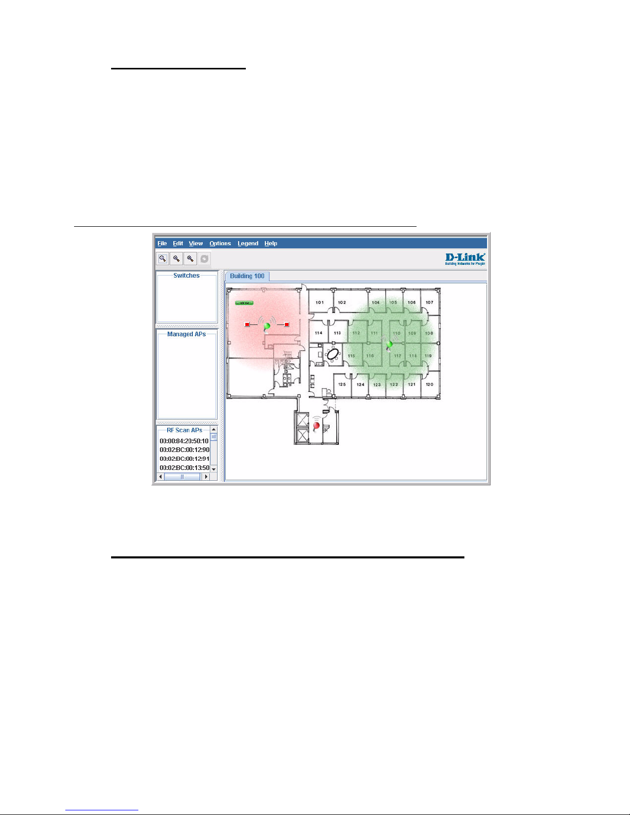
The D-Link Unified Access System includes the WLAN Visualization tool, which provides a
graphical representation of your wireless network through a Web browser. WLAN
Visualization detects and displays the D-Link Unified Switch, D-Link Access Points, other
access points, and all wireless clients associated with the D-Link Access Point. Y ou can import
information about your building layout to customize the network view.
Figure 1 shows an example of a floor plan and network with a D-Link Unified Switch that
manages two APs. The graph also shows a peer switch and a rogue AP in the network.
Figure 1. Sample WLAN Visualization
1 Overview of the D-Link Unified Access System
The WLAN Visualization tool provides an AP power display with color-coded channels to
help you determine where to physically place access points to reduce interference or increase
coverage on your WLAN.
D-Link Unified Access System Topology
The WLAN network topology you use depends on the size and requirements of your network.
Small-to-medium networks mi ght require on ly one Unifi ed Switch tha t manages a few D-Li nk
Access Points. For larger networks that need greater roaming capabilities for wireless clients, a
deployment with multiple peer switches that each manage several APs might be appropriate.
D-Link Unified Access System Topology 23
Page 24
D-Link Unified Access System User Manual
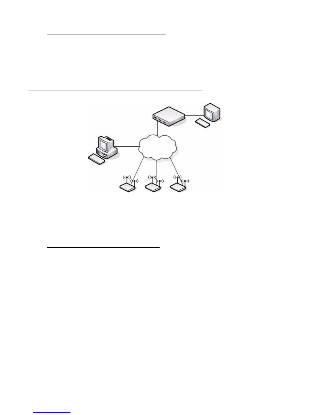
Single Unified Switch Deployment
When you deploy a D-Li nk Acce ss Point, the D-Link Uni fi ed Swi tc h c an automatically detect
the AP and assign a default profile, which includes automatic RF channel selection and
automatic power adjustment. Figure 2 shows a deployment with one D-Link Unified Switch
that manages three D-Link Access Points.
Figure 2. Single Unified Switch with Layer 2 Roaming Support
Unified Switch
L2 Network
Remote Management
Station
Terminal with Direct
Serial Connection
AP 2AP 1 AP 3
When the APs are on t he same subn et and have the same SSID, wir eless cl ients c an seamles sly
roam among the three APs with no interruption in network access. The client keeps the same
IP address and does not need to re-authenticate when it moves into the broadcast area of a
different AP. Configuration changes to the APs are managed by the switch simultaneously or
on a per-AP basis.
Peer Unified Switch Deployment
To support larger networks, you can configure up to four switches as peers, which increases
the size and range of the WLAN. Figure 3 shows a D-Link Unified Access System
deployment that utilizes three peer Unified Switches. Each peer Unified Switch can manage
24 © 2001- 2008 D-Link Corporation. All Rights Reserved.
Page 25
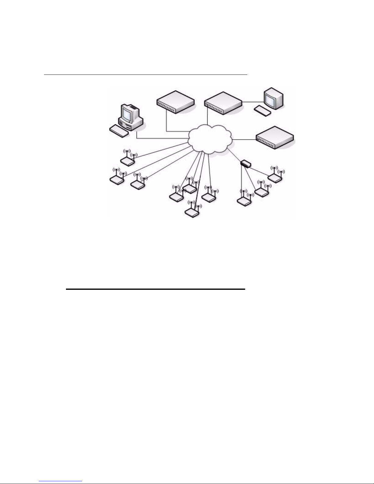
up to 48 access points (DWS-3024 and DWS-3026) or 24 access points (DWS-3024L). The
Unified Switch and the APs it manages do not need to be on the same subnet.
Figure 3. Peer Unified Switch with Layer 3 Roaming Support
Unified Switch 1
Remote Management
Station
Access Points
Managed by Unified Switch 1
Unified Switch 2
L3 Network
1 Overview of the D-Link Unified Access System
Terminal with Direct
Serial Connection
Unified Switch 3
Access Points
Managed by Unified Switch 3
Access Points
Managed by Unified Switch 2
Peer Unified Switches share information about APs and allow Layer 3 roaming among them.
To support this, peer Unified Switches establish IPv4 tunnels so that the wireless client keeps
the same IP address even when the cli ent associates with an access poin t in a different subnet.
The Layer 3 roaming service allows wireless phone users to roam between access points
connected to different subnets without dropping calls.
Understanding the User Interfaces
The D-Link Unified Access System enables centralized manage ment of multip le wireless
access points, which not only facilitates deployment and management, but also enhances
security. The D-Link Unified Access System includes a set of comprehensive management
functions for managing and monitoring the WLAN by using one of the following three
methods:
• Web-based
• Command- Line Interface (CLI)
• Simple Network Management Protocol (SNMP)
Each of the standards-based management methods enables you to configure, manage, and
control the components of the D-Link Unified Access System locally or remotely.
Management is standards-based, with configuration parameters and a private MIB that
provides con trol for functions not completely specifie d in the standar d MIBs.
The method you use to configure and monitor the D-Link Unified Switch depends on your
network size and requirements, and on your preference.
Understanding the User Interfaces 25
Page 26
D-Link Unified Access System User Manual
e
Using the Web Interface
The following Web browers are supported for Web interface access to the switch:
• Microsoft
• Microsoft
Use the following procedures to log on to the Web Interface:
1. Open a Web browser and enter the IP address of the switch in the Web browser address
field.
2. Enter the user name and password into the dialogue box that appears.
The user name and password are the same as those you us e t o log on to the command-li ne
interface. By default, the user name is admin, and there is no password.
3. After the system authenticates you, the System Description page displays.
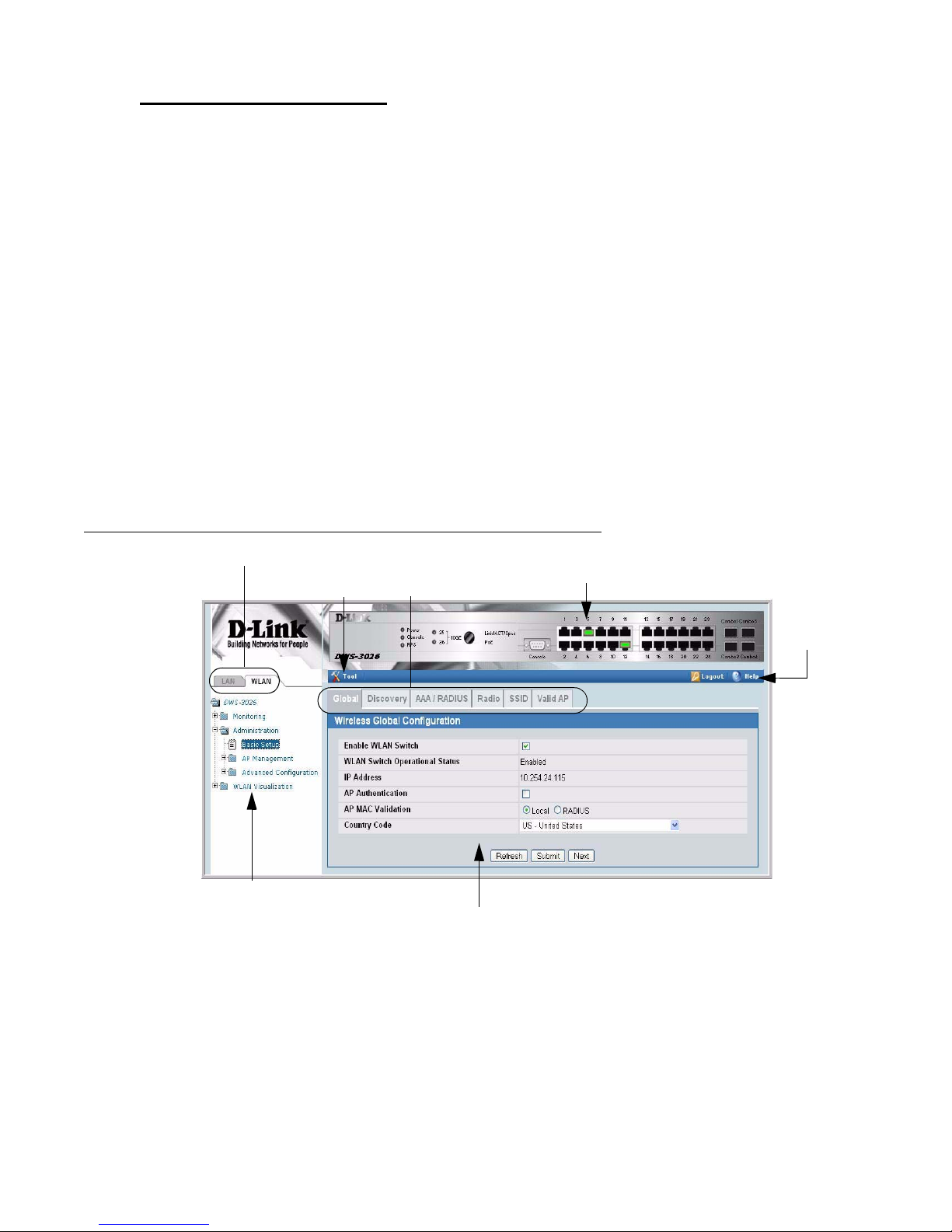
Figure 4 shows the layout of the D-Link Unified Switch Web interface. Each Web page
contains three main areas: interface configuration graphic, the navigation tree, and the
configuration status or options.
®
Windows® Internet Explorer 6.0
®
Windows® Internet Explorer 7.0
Figure 4. Web Interface Layout
LAN and WLAN Tabs
Tools Menu
Navigation Tree
Interface Configuration Graphic
Interface Configuration Graphic
WLAN Tabs
Configuration Status and Options
Help Pag
Access
Interface Configuration Graphic
The interface configuration graphic is a Java™ applet that displays the ports on the D-Link
Unified Switch. This graphic appears at the top of each page to provide an alternate way to
navigate to configuration and monitoring options.
26 © 2001- 2008 D-Link Corporation. All Rights Reserved.
Page 27
Click the port you want to view or configure to see a menu that displays statistics and
configuration optio ns. Click t he menu opti on to acces s the page t hat cont ains the c onfigurat ion
or monitoring op tions. Clic k Logout to log out of th e Web Interface. From the Logout prompt,
click Ok to save your changes and make the changes permanent. Click Cancel to close the
Web Interface without saving your changes.
If you click the graphic but do not click a specific port, the main menu appears. This menu
contains the same option as the navigation menu on the left side of the page.
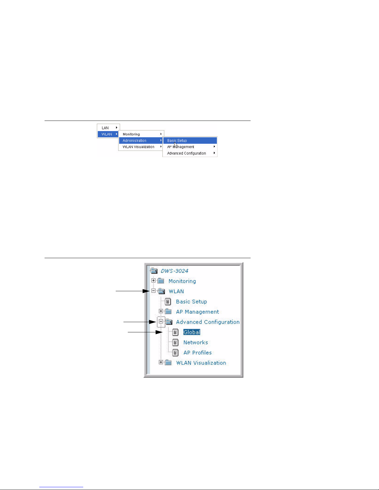
Figure 5. Cascading Navigation Menu
Navigation Menu
A hierarchical-tree view appears to the left of the panel. The tree consists of a combination of
folders, subfolders, and configuration and status HTML pages. Click the folder to view the
options in that folder. Each folder contains either subfol ders or HTML pages, or a combinatio n
of both. Figure 6 shows an example of a folder, subfolder, and HTML page in the navigation
menu. When you click a folder or subfolder that is preceded by a plus (+), the folder expands
to display the contents . If you cl ick an HTML page, a new page displays in the main fr ame. A
folder or subfolder has no corresponding HTML page.
1 Overview of the D-Link Unified Access System
Figure 6. Hierarchical Tree Navigation Menu
Folder
Subfolder
HTML Page
Configuration and Monitoring Options
The panel directly under the graphic and to the right of the navigation menu displays the
configuration information or status for the page you select. On pages that contain
configuration options, you can input information into fields or select options from drop-down
menus.
Understanding the User Interfaces 27
Page 28

D-Link Unified Access System User Manual
Each page contains access t o the HTML-based Help that explains the fiel ds and conf i guration
options for the page. Many pages also contain command buttons.
The following command buttons are used throughout the pages in the Web interface:
Submit Clicking the Submit button sends the updated configuration to the switch.
Configuration changes take effect immediately, but some changes are not
retained across a power cycle unless you save them to the system configuration file.
Save Clicking the Save but t on sa ves the current confi gur ation to the system config-
uration file. When yo u cl i ck Save, changes that you have submitted are save d
even when you reboot the system. To save the configuration, use the Save
Changes link in the Tools menu.
Refresh Clicking the Refresh button refreshes the data on the panel.
WLAN Tabs
Many of the pages in the WLAN folder contain tabs to simplify navigation and to group
functions for a common feature. Click the tab to access a specific page.
NOTE: Other packages in the software suite do not use tabs in the Web interface.
Tools Menu
If you mouse over the Tool icon, a list of the following useful system tools appears:
• Reset Configuration
• Reset Password
• Reboot System
• Save Changes
• Download File
• Upload File
• Multiple Image Services
Each item in the list is a link to the Web page where you can perform the related task.
Using the Command-Line Interface
The command-line interface (CLI ) is a text -based way to mana ge and monitor the system. You
can access the CLI by using a dir ect ser ia l connection or by using a remote logical connection
with Telnet or SSH.
The CLI groups commands into modes according to the command function. Each of the
command modes supports specific commands. The commands in one mode are not available
until you switch to that particular mode, with the exception of the User EXEC mode
commands. You can execute the User EXEC mode commands in the Privileged EXEC mode.
To display the commands available in the current mode, enter a question mark (?) at the
command prompt. T o di splay the ava ilable command keywor ds or parameters, e nter a questi on
mark (?) after each word you type at t he command prompt . If ther e are no additi onal comma nd
28 © 2001- 2008 D-Link Corporation. All Rights Reserved.
Page 29

keywords or parameters, or if additional parameters are optional, the following message
appears in the output:
<cr> Press Enter to execute the command
For more information about the CLI, see the D-Link CLI Command Reference.
The D-Link CLI Command Reference lists each command available from the CLI by the
command name and provides a brief description of the command. Each command reference
also contains the following information:
• The command keywords and the required and optional parameters.
• The command mode you must be in to access the command.
• The default value, if any, of a configurable setting on the device.
The
command shows.
Using SNMP
For D-Link Unified Switch software that includes the SNMP module, you can configure
SNMP groups and users that can manage traps the SNMP agent generates.
1 Overview of the D-Link Unified Access System
show commands in the document also include a description of the information that the
The D-Link Unified Switch uses both standard public MIBs for standard functionality as well
as a number of additional private MIBs for additional functionality supported by the switch.
All private MIBs b egin with a “DLINK-” p refix. The mai n obje ct for int erface configur ation is
in DLINK-SWITCHING-MIB, which is a private MIB. Some interface configurations also
involve objects in the public MIB, IF-MIB.
SNMP is enabled by default. The System Description Web page, which is the page the
displays after a suc cessf ul lo gin, and t he
show sysinfo command display the i nform ation you
need to configure an SNMP manager to access the switch.
Any user can connect to the switch using the SNMPv3 protocol, but for authentication and
encryption, you need to configure a new user profile. To configure a profile by using the CLI,
see the SNM P section in the D-Link CLI Command Reference. To configure an SNMPv3
profile by using the Web interface, use the following steps:
1. Select LAN > Administration > User Accounts from t he hierar chical t ree on the le ft side
of the Web interface.
2. Using the User pull-down menu, select Create to create a new user.
3. Enter a new user name in the User Name field.
4. Enter a new user password in the Password field and then retype it in the Confirm
Password field.
To use SNMPv3 Authentication for this user, set a password of eight or more
alphanume ric characters.
5. To enable authentication, use the Authentication Protocol pull-down menu to select
either MD5 or SHA for the authentication protocol.
6. To e nable encrypt ion, u se the Encr yption Prot ocol pull -do wn menu t o sele ct DES for the
encryption scheme. Then, enter an encryption code of eight or more alphanumeric
characters in the Encryption Key field.
Understanding the User Interfaces 29
Page 30

D-Link Unified Access System User Manual
7. Click Submit.
To access configuration information for SNMPv1 or SNMPv2, click LAN > Administration
> SNMP Manager and click the page that contains the information to configure.
Wireless System Features and Standards Support
In addition to core switching features, the D-Link Unified Switch supports the following
features and standards:
•IP Tunneling
• Spanning Tree
• Auto detection and configuration of APs
• Automatic Peer-Switch Discovery
• Automatic or Manual RF Channel Assignment
• Automatic or Manual AP Power Adjustment
• AP Authentication
• Client Authentication
• Load Balancing
• RF Scan and AP Sentry Mode
• Dual Radio Support
• Multiple Mode Support for Radios:
- IEEE 802.11a
- IEEE 802.11b
- IEEE 802.11g
- Dynamic Turbo 5Ghz
- Dynamic Turbo 2.4 Ghz
• IEEE 802.11h (TPC and DFS)
• Security Standard Support:
- WEP (64, 128)
- WEP (152)
-TKIP
- AES & CCMP
- Inhibit SSID broadcast
-WPA (Personal)
- WPA (Enterprise)
- WPA2 (Personal) 802.11i
- WPA2 (Enterprise) 802.11i
• MAC Authentication
• Multiple BSSID/VLANs
• Security and Authentication Settings per SSID
• VLAN Support
• IEEE 802.11d (Country Code)
• IEEE 802.11e (WMM)
• RADIUS support
• WLAN Visualization (NMS like product for APs)
• Mobility
- Inter- and Intra- Subnet Fast Roaming
- Key caching
30 © 2001- 2008 D-Link Corporation. All Rights Reserved.
Page 31

1 Overview of the D-Link Unified Access System
- Tunneled and distributed forwarding
- Peer-to-peer WLAN switch roaming
• Intrusion Detection
- Rogue AP detection
- Rogue Client detection
- Station blacklisting
- Ad-hoc network detection
• Network Management
- SNMP v1, v2c, v3
-CLI
- SYSLOG
- Up to 24 APs (DWS-3024L) or 48 APs (DWS-3024 and DWS-3026) per switch
- Auto AP image download
- D-Link WLAN Private MIB
• Simultaneous AP upgrade
• Centralized data forwarding via tunneling for fast roaming and unified QoS
• AP RF Monitoring
• Configuration & Firmware Upload/Download
Each AP supports 8 virtual access points (VAPs) per radio. You can configure a unique SSID
and security policy on each VAP. The following list shows some of the D-Link Access Point
features and standards support:
• WLAN and IEEE Standards
- IEEE 802.11a
- IEEE 802.11b
- IEEE 802.11d
- IEEE 802.11e (WMM)
- IEEE 802.11g
- IEEE 802.11h
- IEEE 802.11i (WPA2)
- IEEE 802.1X - 2001 Port Based Network Access Control
- IEEE802.3af PoE Support
• WLAN RF Features
- RF Scan
- Transmit Pow er Control
- Load Balancing
- Dynamic Channel Assignment
- Dual Radio Support
- Atheros Dynamic Turbo 5Ghz
- Atheros Dynamic Turbo 2.4 Ghz
- TELEC 4.9GHZ 802.11a modes
- Wireless S tatistics
- Virtual AP with Multiple BSSIDs/SSIDs
• WLAN AP Management
- CLI Management (SSH)
- Web Management (SSL support)
- TFTP
Wireless System Features and Standards Support 31
Page 32

D-Link Unified Access System User Manual
• WLAN Networking and QoS
- Switch/AP Discovery
- Tunneling
- WMM (802.11e)
- 802.1p (MAC layer QoS support)
-DSCP
- Dynamic VLANs
- MAC ACLs
- SpectralLink Priority Support
• WLAN Encryption and Security
-WEP
-TKIP
- AES & CCMP
- Rogue AP detection
- Ad-Hoc Client Detection
- Inhibit / Ignore SSID broadcast
- Weak IV avoidance
- MAC Authentication
- Port/IP blocking
- RADIUS support
-EAP
- PEAP
- TLS and TTLS
- WPA (Personal, Enterprise)
- WPA2 (Personal, Enterprise) 802.11i
- 802.1X Supplicant
- Client Authentication
- Firewall/IP filtering support
32 © 2001- 2008 D-Link Corporation. All Rights Reserved.
Page 33

Planning the D-Link Unified Access
System Network
The D-Link Unified Access System provides continuous, high-speed access between your
wireless and Ethernet devices. It is an advanced, scalable, standards-based solution for
wireless networking. The D-Link Un ified Access System enables wireless local area network
(WLAN) deployment while providing state-of-the-art wireless networking features.
This chapter contains the following sections to help you plan your D-Link Unified Access
System:
• System Requirements
• WLAN Topology Considerations
• Network Planning to Support Layer 3 Roaming
2
System Requirements
You accomplish the initial D-Link Unified Switch configuration by using a direct cable
connection. After the initial configuration, you can manage the Unified Switch by using a
Web-based user interface (UI), command line interface (CLI), or SNMP. The following list
describes the minimum requirements you need to install and manage the D-Link Unified
Switch:
• VT100 terminal or PC with terminal-emulation software
• Direct serial connection to the console port of the D-Link Unified Switch
• Remote system for management access with a Web browser, Telnet/SSH client, or SNMP
manager
To support security and networking features in D-Link Unified Access System, you can use
the following optional equipment on your network:
• A RADIUS server for authentication and accounting features for wireless clients, access
points, and peer Unified Switches
• Network equipment that supports VLANs
• A DHCP server to dynamical ly a ssi gn n et wo rk i nf orma ti on t o the switch and to all ac ces s
points
• A Syslog server for external logging
System Requirements 33
Page 34

D-Link Unified Access System User Manual
Figure 7 shows a simple D-Link Unified Access System deployment with required and
optional equipment for setup and operation.
Figure 7. D-Link Unified Access System Components
AP 1
Unified Switch
Terminal with Direct
Serial Connection
AP 2
AP 3
Wireless Clients
Remote Management
Station
NOTE:
The D-Link Unified Switch has a bui lt -i n DHCP ser ver. I f you do not al rea dy
Network
RADIUS Server
DHCP Server
Syslog Server
have a DHCP server on your network, you can configure the Unified Switch
to assign network information to network hosts.
As the figure shows, the wireless clients can be laptop computers, personal digital assistants
(PDAs), smart phones, or any other hand-held, portable or stationary device equipped with a
Wi-Fi adapter and supporting drivers. In order to connect to the access point, wireless c lients
need the software and hardware the following list describes:
• A portable or built-in Wi-Fi client adapter that supports one or more of the IEEE 802.11
modes in which you plan to run the access point. (IEEE 802.11a, 802.11b, 802.11g)
• Client software such as Microsoft Windows Supplicant configured to associate with the
WLAN.
• Wireless security software that is compatible with the authentication mode the access
point uses.
WLAN Topology Considerations
The D-Link Unified Switch adds WLAN functionality to the base switching and IP routing
features standard in most Layer 2/3 switches. Where you put the D-Link Unified Switch in
your network depends o n the size , require ments, and existing to pology of you r networ k. If you
are adding a wireless network to an exi st ing networ k, your requ ir ement s ar e different than the
requirements of someone who does not have a sufficient LAN infrastructure.
Since the D-Link Unified Switch has Layer 2/3 switching funct ions as well as WLAN data and
management functions, you can connect D-Link Access Points, wired PCs, or other network
34 © 2001- 2008 D-Link Corporation. All Rights Reserved.
Page 35

equipment such as hubs, routers, or other switches directly to the 10/100/1000 Mbps Ethernet
ports on the switch. All connections to the D-Link Unified Switch must be wired connections
since the switch does not have any radios.
In Figure 8, the D-Link Unified Switches are both LAN and WLAN switches that handle
traffic from end users connected to the wired LAN as well as traffic from the D-Link Access
Points. In the d iagra m, Buildi ng 1 a nd Buil ding 2 ha ve a D- Link Uni fied Swit ch on ea ch fl oor.
Figure 8. Wiring Closet Topology
2 Planning the D-Link Unified Access System Network
Building 1
Floor 2
Building 1
Floor 1
APs
APs
APs
Unified Switch
Unified Switch
L2/L3 Distribution Switch
APs
Unified Switch
To Network
Backbone
Unified Switch
Unified Switch
Unified Switch
APs
APs
Building 2
Floor 2
APs
Building 2
Floor 1
APs
The four D-Link Unified Switches are in the same peer group. This allows wireless clients to
roam between floors and between buildings without the need to re-authenticate. Additionally,
each Unifi ed Switch shares its list of managed APs and wireless clients with the switches in
the peer group so that the APs and wireless clients are not reported as rogues (unknown).
The topology in Figure 8 works well if you need to add, upgrade, or replace LAN switches on
your network.
NOTE: When tunneled clients are used in conjunction with peer switches, one of the
peer switches must be configured as a default gateway for the tunneled clients. Normally the default gateway routes all traffic from the client’s subnet to
other subnets, however in a peer switch network the Unified Switch that manages the AP to which the cl ient i s assoc iated routes the fra mes i nto the remote
subnets. This mean s t ha t each peer switch must have routing tabl e entries that
enable it to route frames to every subnet in the network.
WLAN Topology Considerations 35
Page 36

D-Link Unified Access System User Manual
Figure 9 shows two D-Link Unified Switches in the network data center. In this deployment,
the switches do not connect directly to APs or end-user nodes.
Figure 9. Data Center Topology
APs
LAN Switch
Unified Switches
Network
Backbone
Data Center
LAN Switch
APs
The data center topology is a good solution in networks where the goal is to add a wireless
LAN to a network wit h min imal c hanges to the existi ng network. T r affic from wireless clients
to the APs is either tun neled t hrough t he Unifi ed Switch or tagge d with a VLAN I D by the AP
and handled accordingly. If the traffic is tagged, it might not pass through the Unified Switch.
Access Point-to-Switch Discovery
To enable the AP and Unified Switc h to di sc over eac h other, you can us e one of the following
four methods:
• Enter the IP address of th e Unified Switch into the AP
• Enter the IP address of th e AP into the Unified Switch
• Configure the DHCP server to pass the IP address of the U nified S witch to the A P in DH CP
option 43
• Use the D-Link Wireless Device Discovery Protocol
The AP-to-switch dis covery method you use depen ds on y our ne twork top ology. For example,
if the Unified Switch and AP are in the same Layer 2 multicast domain, we recommend that
you use the D-Link Wireless Device Discovery Protocol.
These options are discussed in more detail in “Discovering Access Points and Peer Switches”
on page 61.
Access Point Placement
D-Link Access Points can be on the same subnet as the switch or on a different subnet. You
can connect the AP directly to the Unified Switch or to another networking device. The range
36 © 2001- 2008 D-Link Corporation. All Rights Reserved.
Page 37

2 Planning the D-Link Unified Access System Network
of the D-Link Access Point is about 100 meters, but the range is affected by various
environmental factors.
To maximize the range, use the following guidelines for the placement of the AP:
• Place the AP in an area where you expect wireless clients will operate.
• Elevated locations, such as on top of a shelf are preferred to increase line-of-sight access.
• A voi d plac ing t he AP near sour ces of inter fere nce, su ch as PCs , microwa ves, and 2.4 GHz
cordless phones.
• Keep the AP away from large metal surfaces.
• Position the antenna horizontally to increase the up-and-down range, or position it
vertically to increase side-to-side coverage.
• When APs are within broadca st ran ge of each ot her, use non-int erfer ing RF chan nel s (five
channels apart for the 802.11b/g radio).
How close you place APs to each other depends on the RF transmission power level, the
number of wireless clients on your network, and the channels the APs use. The RF signal
transmission power level directly affects the broadcast range of the AP signal. If the power
level is too low, wireless clients will not detect the signal or experience poor WLAN
performance. If the power level is too high, the RF signal might interfere with other APs
within range. If the RF signal broadcasts beyond the physical confines of your building or
network, it increases the security threat to the network.
When the power level is high a nd RF bro adcast area is larger, more wire less clients can detect
the signal and associate with the AP. An increase in the number of wireless clients that
associate with t he AP gene rall y means t hat th e amou nt of t raf fi c the AP re ceives and tr ansmi ts
increases as well. You can limit the network utilization level allowed on an AP to prevent
wireless clients from experiencing slower network speeds. However, once the network
utilization is reached, new clients are unable to associate with the AP. If an AP frequently
reaches the network utilization limit, it might indicate that you should add another AP nearby.
You can configure the APs to automatically adjust the power and channel to the needs of the
network environment.
Network Planning to Support Layer 3 Roaming
With the D-Link Unified Access System, mobile stations can maintain their IP connections
while roaming from one access poi nt to anot her even when these access points are att ach ed to
different IP subnets. This feature enables Voice over IP (VoIP) deployments on 802.11
subnetted networks.
It is often necessary to subdivide the enterprise IPv4 network into several subnets. An access
point may be directly attached to the Unified Switch or it may be located several router hops
away from the Unified Switch.
To support layer 3 roaming, it is necessary to keep the wireless client's IP address unchanged
while it roams over different subnets. This guarantees seamless roaming as the IP changeover
process does not take place while wireless clients roam across subnet borders.
Network Planning to Support Layer 3 Roaming 37
Page 38

D-Link Unified Access System User Manual
The D-Link Unified Access Sys te m prov ides two ways to prevent the IP ad dre ss of a roaming
client from changing:
1. You can associate the SSID for roaming with a VLAN and configure the network devices
on your network to allow VLAN trunking across different subnets. By doing this, the
client will always stay in the same VLAN and retain the same IP address while it roams.
This approach is appropriate when it is not difficult to configure VLAN trunking on
devices in the network.
2. You can associate the SSID for roaming with a tunneled subnet. In this case, the switch
uses IP tunneling to establish a link between itself and the access point it manages. The
switch routes all IPv 4 unicast fr ames so tha t the wirel ess networks are perc eived as loc ally
attached networks by the Unified Switch.
Routing must be enabled on the switch to support L3 roaming.
Figure 10 shows a single wireless client as it roams among three APs in three different
subnets. A D-Link Unified S witch cont rols the three APs. When t he wirel ess client connect s to
any of the APs, it receives an IP address from the Unified Switch that is in the L3 Tunnel
subnet. As the client roams among the APs, it maintains its connection to the WLAN and
keeps the same IP address that the switch originally assigned it. All traffic the client sends and
receives goes through the switch.
Figure 10. Inter-Subnet Roaming
Client
IP: 10.20.20.12
In the tunneling configuration, you can use ACL lists and QoS parameters to ensure that timesensitive traffic, such as VoIP, takes priority ov er other WLAN traffic.
For many IP phone systems, you must connect a call server to a wired port on the L3 tunnel
subnet. You must also either configure DHCP relay on the switch or co nfigure the switch to be a
DHCP server . APs, pee r switches, and other routers canno t be connected to the L3 tunnel subne t.
AP 2
IP: 192.168.38.66
Client
IP: 10.20.20.12
AP 1
IP: 192.168.24.173
AP 3
IP: 192.168.85.49
Client
IP: 10.20.20.12
Unified Switch
L3 Tunnel Subnet
IP: 10.20.20.0
For more information a bout L3 tun nelling a nd how to co nfigure i t, see “Configur ing a VAP for
L3 Tunnels” on page 99 and Appendix C, “L3 Roaming Example”on page 213.
38 © 2001- 2008 D-Link Corporation. All Rights Reserved.
Page 39

Installing the Hardware
This chapter provides instructions for installing the D-Link DWS-3024, DWS-3024L, and
DWS-3026 switch hardware. The following sections describe this installation process:
• Hardware Overview
- Front Panel Components
- LED Indicators
- Rear Panel Description
- Side Panels
• Installation
- Package Contents
- Install ation Guidelin es
- Installing the Switch without the Rack
- Installing the Switch in a Rack
- Powering On the Switch
- Installing the SFP ports
- Installing the Optional Modules
- Connecting to the External Redundant Power System
• Connectin g the Switch
- Connecting the Switch to the Network
- Connecting the Swit ch and AP Directly
- Connecting the Switch and AP through the L2/L3 Network
- Connecting to the Core Network
3
Hardware Overview
This section describes the font, back, and side panels and the LED indicators on the switch.
The DWS-3024/DWS-3024L and DWS-3026 have slightly different front and back panels
based on the available features.
Hardware Overview 39
Page 40

D-Link Unified Access System User Manual
Front Panel Components
The front panel of the Switch consists of LED indicators for Power, Console, RPS, PoE, and
Link/Act/Speed for each port on the Switch including 10GE Ports for optional modules and
SFP port LEDs. Table 2 describes the LED indicators in more detail.
Figure 11. Front Panel View of the DWS-3024L as Shipped
Figure 12. Front Panel View of the DWS-3024 as Shipped
Figure 13. Front Panel View of the DWS-3026 as Shipped
40 © 2001- 2008 D-Link Corporation. All Rights Reserved.
Page 41

LED Indicators
The Switch supports LED indicators for Power, Console, RPS, PoE, and Port LEDs includ ing
10GE port LEDs for optional module inserts on the DWS-3026.
Figure 14. LED Indicators on DWS-3024L
Figure 15. LED Indicators on DWS-3024
3 Installing the Hardware
Figure 16. LED Indicators on DWS-3026
Hardware Overview 41
Page 42

D-Link Unified Access System User Manual
The following table d escri bes t he LE Ds and t he Mode Sel ect Bu tton o n the f ron t pane l of each
Switch.
Tabl e 2. LED Description
LED Description
Power This LED lights green after powering the Switch on to indicate the ready
state of the device. The indicator is dark when the Switch is no longer
receiving power (i.e powered off).
Console This LED blinks green during the Power-On Self Test (POST). When the
POST is finished, the LED goes dark. The indicator lights steady green when
an active console link is in session via the RS-232 console port.
RPS This LED lights when the internal power has failed and the RPS has taken
over the power supply to the Switch. Otherwise, it remains dark.
Link/Act/Speed
and PoE Mode
Port LEDs One row of LEDs for each port is located above the ports on the front panel.
You can change the mode of the LEDs over each port to display the
information about the link, activity, and speed of a port or whether 802.3af
Power Over Ethernet (PoE) is supporting devices attached to the port.
To change the LED mode from Link/Act/Speed to PoE and vice versa, press
the LED Mode Select Button.
The indicator above the left side of a port corresponds to the port below the
indicator in the upper row of ports. The indicator above the right side of a
port corresponds to the port below the indicator in the lower row of ports.
The port LEDs show information about link, activity, and speed on the port
or Power over Ethernet usage on the port, depending on the LED mode you
select.
For Link/Act/Speed Mode:
• Solid Green—Indicates a valid 1000Mbps link on the port, while a
• Solid Amber—Indicates a valid 10 or 100Mbps link on the port.
• Blinking Amber—Indicates activity on the port (at 100Mbps).
• Off—No link/activity on the port.
For PoE Mode:
• Solid Green—Power feeding (802.3af-compliant PD was detected).
• Blinking Amber—PoE port ERROR (non-standard PD connected, Under
• Off—No power feeding (no PD detected, or no connection)
blinking green light indicates activity on the port (at 1000Mbps).
load state according to 802.3af (current is below I min), Overload state
according to 802.3af (current is above I cut), hardware problems
preventing port operation, power budget exceeded, short condition was
detected at a port delivering power, temperature overload at the port,
succession of Underload and Overload states caused port shutdown (may
be caused by a PD's DC/DC fault)...etc.)
42 © 2001- 2008 D-Link Corporation. All Rights Reserved.
Page 43

Tabl e 2. LED Description
LED Description
10GE Port LEDs (DWS-3026 only) A st eady gre e n li ght deno te s a valid link on the port whi le
a blinking green light indicates activity on the port. These LEDs remain dark
if there is no link/activity on the port.
Combo SFP Ports The LED indicators for the Combo ports are located above the ports and
numbered 1 – 4 for Combo 1, Combo 2, Combo 3, and Combo 4 ports. A
steady green light indicates a valid link on the port while a blinking green
light indicates activity on the port. These LEDs remain dark if there is no
link/activity on the port.
Rear Panel Description
The AC power connector is a standard three-pronged connector that supports the power cord.
Plug the female connector of the provided power cord into this socket, and plug the male side
of the cord into a power outlet. The Switch automatically adjusts its power setting to any
supply voltage in the range from 100 ~ 240 VAC at 50 ~ 60 Hz.
The rear panel also includes an outlet for an optional external power supply. When a power
failure occurs, the optional external R PS will immediately and automatically assume the
power supply for the Switch.
3 Installing the Hardware
The rear panel of the DWS-3024/DWS-3024L contains an AC power connector, a system fan
vent, and a redundant power supply connector.
Figure 17. Rear panel view of DWS-3024/DWS-3024L
The rear panel of the DWS-3026 contains an AC power connector, a system fan vent, a
redundant power supply connector and two empty slots for optional 10GE module inserts.
Figure 18. Rear panel view of DWS-3026
Side Panels
The system fans and heat vent s locat ed on each si de of the Switch di ssipa te heat . Do not blo ck
these openings. Leave at least 6 inches of space at the rear and sides of the Switch for proper
ventilation. Without proper heat dissipation and air circulation, system components might
overheat, which could lead to system failure and severely damage components.
Hardware Overview 43
Page 44

D-Link Unified Access System User Manual
Installation
This section describes how to install the Switch on a flat surface or in a standard equipment
rack. It also describes how to install the optional components for the Switch.
Package Contents
Open the shipping carton of the Switch and carefully unpack its contents. The carton should
contain the following items:
1. One Switch
2. One AC power cord
3. Mounting kit (two brackets and screws)
4. Four rubber feet with adhesive backing
5. RS-232 console cable
6. One CD Kit for DWS-3000 Series Administrator’s Guide and CLI Reference Guide
7. Registration card & China Warranty Card (for China only)
If any item is missing or damaged, please contact your local D-Link Reseller for replacement.
Installation Guidelines
Please foll ow these guide lines for sett ing up the Swit ch:
• Install the Switch on a sturdy, level surface that can support at least 6.6 lb. (3 kg) of
weight. Do not place heavy objects on the Switch.
• The power outlet should be within 1.82 meters (6 feet) of the Switch.
• Visually inspect the power cord and see that it is fully secured to the AC power port.
• Make sure that there is proper heat dissipation from the Switch and adequate ventilation
around the Switch. Leave at least 10 cm (4 inches) of space at the front and rear of the
Switch for ventilation.
• Install the Switch in a fairly cool and dry place for the acceptable temperature and
humidity operating ranges.
• Install the Switch in a site free from strong electroma gnetic field generators (su ch as
motors), vibration, dust, and direct exposure to sunlight.
• When installing the Switch on a level surface, attach the rubber feet to the bottom of the
device. The rubber f eet c ushion the Switch, pro tec t the casing from sc ra tches, and prevent
it from scra tching other surfaces.
44 © 2001- 2008 D-Link Corporation. All Rights Reserved.
Page 45

Installing the Switch without the Rack
First, attach th e r ubbe r f eet included with the Switch if installing on a deskt op or shelf. Attach
these cushioning feet on the bottom at each corner of the device. Allow enough ventilation
space between the Switch and any other objects in the vicinity.
Figure 19. Prepare Switch for Installation on a Desktop or Shelf
Rubber Feet
3 Installing the Hardware
Installing the Switch in a Rack
The Switch can be mounted in a standard 19" rack. Use the following diagrams as a guide.
Figure 20. Fasten Mounting Brackets to Switch
Installation 45
Page 46

D-Link Unified Access System User Manual
Fasten the mounting brackets to the Switch using the screws provided. With the brackets
attached securely, the Switch can be mounted in a standard rack as shown in Figure 21.
Figure 21. Mounting the Switch in a Standard 19" Rack
Powering On the Switch
Plug one end of the AC power cord into the power connector of the Switch and the other end
into the local power source outlet.
After powering on the Switc h, the LED indic ators wil l momentarily bl ink. This bl inking of t he
LED indicators represents a reset of the system.
Power Failure
As a precaution, in the event of a power failure, unplug the Switch. When power is resumed,
plug the Switch back in.
Installing the SFP ports
The DWS-3000 series switches are equipped with SFP (Small Form-factor Pluggable) ports,
which are to be used with fiber-optical transceiver cabling in order to uplink various other
networking devices for a gigabit link that may span great distances. These SFP ports support
full-duplex transmissions, have auto-negotiation and can be used with DEM-310GT
(1000BASE-LX), DEM-311GT (1000BASE-SX), DEM-314GT (1000BASE-LH) and DEM-
46 © 2001- 2008 D-Link Corporation. All Rights Reserved.
Page 47

315GT (1000BASE-ZX) transceivers. See the figure below for installing the SFP ports in the
Switch.
Figure 22. Inserting the Fiber-Optic Transceivers into the Switch
3 Installing the Hardware
Installing the Optional Modules
The rear panel of t he DWS-3 026 includes two open slot s t hat may be equipped with the DEM410X 1-port 10GE XFP uplink module, or a DEM-410CX 1-port 10GBASE-CX4 uplink
module, both sold separately.
Adding the DEM-410X optional module allows the switch to transmit data at a rate of ten
gigabits per second. The module port(s) are compliant with standard IEEE 802.3ae, support
full-duplex transmissions only and must be used with XFP MSA-compliant transceivers.
The DEM-410CX uses copper wire medium, not opt ic fiber and the refore has a trans mit length
limit up to 1 meters. Comp liant with the IE EE802.3ak standard, this module uses a 4-lane
copper connector for data transfer in full-duplex mode.
To install these modules in the DWS-3026 Switch, follow the steps listed in this sect ion.
CAUTION: Before adding the optional module, make sure to disconnect all power
sources connected to the Switch. Failure to do so may result in an
electrical shock, which may cause damage, not only to the individual but
to the Switch as well.
At the back of the Switch to the left are the two slots for the optional modules. These slots
must be covered with the faceplate if the slots are not being used. To install a module in an
available slot, remove the faceplate by loosening the screws and pulling off the plate.
Installation 47
Page 48

D-Link Unified Access System User Manual
The front panels of the available modules are shown here:
Figure 23. Front Panel of the DEM-410X
Figure 24. Front Panel of the DEM-410CX
Install the Module
Unplug the Switch before removing the faceplate covering the empty slot. To install the
module, slide it in to the available slot at the rear of the Switch until it reaches the back, as
shown in the following figure. Gently, but firmly push in on the mo dule to secure it to the
Switch. The module should fit snugly into the corresponding receptors.
Figure 25. Inse rting the optional module into the Switch (DWS-3026)
48 © 2001- 2008 D-Link Corporation. All Rights Reserved.
Page 49

Now tighten the two screws at adjacent ends of the module into the available screw holes on
the Switch. The upgraded Switch is now ready for use.
Figure 26. D WS-3026 with optional DEM-410X module installed
Connecting to the External Redundant Power System
The Switch supports an external redundant power system (RPS). The diagrams below
illustrate a proper RPS power connection to the Switch. Please co nsult the documentation fo r
information on power cabling and connectors and setup procedure.
3 Installing the Hardware
Figure 27. RPS Connector
DWS-3026
DPS-600
Connecting the Switch
This section describes how to connect the following nodes:
• Switch to the network
• AP directly to the Switch
• AP to the Switch through the L2/L3 network
• Switch through the 10GB uplink to the network core
NOTE: All 24 high-performance N-Way Ethernet ports can support both MDI-II and
MDI-X connections.
RPS Connector
Connecting the Switch 49
Page 50

D-Link Unified Access System User Manual
Connecting the Switch to the Network
You can use any of the 1000BASE-T ports, 10GB ports, or fiber-optic ports to connect the
Switch to your network. The type of port you use to connect the switch depends on your
network requirements and the type of node to which you conn ect the Swi tch, which might be a
hub, router, or another switch.
There is a great deal of flexibility on how connections are made using the appropriate cabling.
• Connect a 10BASE-T hub or switch to the Switch via a twisted-pair Category 3, 4 or 5
UTP/STP cable.
• Connect a 100BASE-TX hub or switch to the Switch via a twisted-pair Category 5 UTP/
STP cable.
• Connect 1000BASE-T switch to the Switch via a twisted pair Category 5e UTP/STP
cable.
• Connect a switch supporting a fiber-optic uplink to the Switch's SFP ports via fiber-optic
cabling.
• Change the Switch to PoE mode using the Mode Select button. When in PoE Mode, the
Switch works with all D-Link 802.3af capable devices.
The Link/Act LEDs for each UTP port will light green or amber when the link is valid. A
blinking LED indicates packet activity on that port.
Connecting the Switch and AP Directly
You can connect one or more DWL-3500AP or DWL-8500AP access points directly to the
Switch by using a straight-through or crossover UTP cable.
Figure 28. Switch and AP Connected Directly
UTP Cable
Access Point
50 © 2001- 2008 D-Link Corporation. All Rights Reserved.
Page 51

Connecting the Switch and AP through the L2/L3 Network
The Switch can discover and manage APs whether they are directly connected, connected
through a device in the same subnet, or connected to different subnets.
Figure 29. Switch and APs Connected Through Network
L2/L3 Network
3 Installing the Hardware
Access Point
Connecting to the Core Network
The optional 10GB ports on the DWS-3026 are ideal for uplinking to the core network.
Connections to the Gigabit Ethernet ports are made using a fiber-optic cable or Category 5e
copper cable, depending on the type of port. A valid connection is indicated when the Link
LED is lit.
Figure 30 shows the rear panel of the DWS-3026 with the optional DEM-410X module.
Figure 30. Switch Connected to Network Core
Fiber Optic Cable
Access Point
Core Network
Connecting the Switch 51
Page 52

D-Link Unified Access System User Manual
52 © 2001- 2008 D-Link Corporation. All Rights Reserved.
Page 53

Installing the D-Link Unified Access
System
This chapter contains the following sections to help you install your D-Link Unified Access
System network:
• System Deployment Overview
• Connecting the Switch to the Network
• Enabling the WLAN Features on the Switch
• Preparing the Access Points
• Discovering Access Points and Peer Switches
• Authenticating and Validating Access Points
4
System Deployment Overview
To setup and deploy the D-Link Unified Access System solution, use the following general
steps:
1. Plan the WLAN network topology.
Decide where to locate each access point to maximize accessibility to the WLAN by
wireless clients an d to mi nimi ze r adi o f requency (RF) interfer ence by ot her ac cess points.
You should also determine how to integrate the D-Link Unified Switch into your existing
network topology. For more information about planning the WLAN topology, see
“WLAN Topology Considerations” on page 34.
2. Install and configure the D-Link Unified Switch.
T o inst all and c onfigure the swi tch, you n eed a seri al connec tion to the switc h, or you must
connect to the switch from a host in the same subnet as the switch default IP address
(10.90.90.90/8). From the initial connection to the switch, you can configure basic
network information or enable the DHCP client on the switch to acquire this information
automatically.
3. Enable the WLAN switch function and assign an IP address to the WLAN switch
interface.
The WLAN features on the switch are enabled by default. The WLAN feature must be
System Deployment Overview 53
Page 54

D-Link Unified Access System User Manual
enabled in order for the switch to discov er and validate D-Link Acc ess Points. If the
routing mode is disabled, the Unified Switch function uses the IP address of the network
interface. If routing is ena bled, the switch uses a loopb ack or routing interface for t he
wireless functions. Changing the IP address of the network interface automatically
disables and re-enables the wireless function. Enabling routing also disables and reenables the wireless function.
4. Configure the default AP Profile settings th at the access point will use after the switch
validates it.
When the switch successfully validates an access point, it sends the AP Profile to the
access point. The AP Profile contains all of the access point configuration information,
such as the radio, security, and SSID settings. You can configure all of the AP settings
before or after the switch validates an AP. For information about configuring the default
AP profile , see Chapter 5 , “Configuring Access Point Settings” on page 83.
5. Prepare and deploy D-Link Access Points and enable AP-to-switch discovery.
After you connect an AP to the network and it obtains an IP address (either statically or
dynamically by using DHCP), the Unified Switch can automatically discover the AP.
However, if your network uses IEEE 802.1X authentication or you require the AP to be
authenticated by the switch upon discovery, you must log on to the AP and configure
security information.
6. Authenticate and validate the APs.
You can optionally configure the Unified Switch so that it only manages APs that it
authenticates. You can use the local database or an external RADIUS database for AP
authentication. Whether or not you require AP-to-Unified Switch authentication, the
switch must be able to validate an AP before it can ma nage the AP. For the sw itch to
validate the AP, you must add the MAC address of each AP to the AP database on the
switch or to the database on an external RADIUS server.
Once you validate the AP, you can use the switch to manage the AP and to view client
associations, status, and statistics.If you follow the procedures in this chapter, the APs will
have the default configuration profile. The default AP Profile settings are listed in
Appendix A.
CAUTION: The default AP profile does not use a security mechanism for wireless
client asso ciations. All wireless clients will be able to connect to a n AP
and access your network.
To prevent unauthorized access to the network by wireless clients, you can configure security
on the default profile before you deploy the APs, or you can create additional AP profiles to
assign the APs when you add them to the Valid AP database. For information about how to
configure default profile settings, see Chapter 5, “Configuring Access Point Settings” on
page 83.
You can use the switch to create multiple AP profiles to assign the APs that you deploy on
your network. For each profile, you can define information such as RF configuration, QoS
configuration, and virtual AP (VAP) configuration. For information about AP profiles, see
“AP Profiles, Networks , and the Local Database” on page 83. For information about creating
and configuring a new AP profi l e, se e “Cr eat in g, Conf ig uring, and Managing AP Profiles ” on
page 155.
54 © 2001- 2008 D-Link Corporation. All Rights Reserved.
Page 55

4 Installing the D-Link Unified Access System
Connecting the Switch to the Network
After you perform the physi ca l ha rdware installation, y ou nee d to connect the D-Link Unified
Switch to the network. The default IP address of the switch is 10.90.90.90/8, and DHCP is
disabled by default. If you want to enable DHCP on the switch or assign a different static IP
address, you must connect to the switch and change the default settings.
You can connect to the switch through Telnet or a Web browser from a host on the 10.0.0.0/8
network, or you can connect to the switch through the console port (RS-232 DCE). After you
connect to the switch, you can provide network information or enable the DHCP client.
To connect to the switch from a host on the 10.0.0.0 network, enter the default IP address of
the switch (10.90.90.90) into the address field of a Web browser or a Telnet client.
To connect to the console port and provide network information, use the following steps:
1. Using a null-modem cable, connect a VT100/ANSI terminal or a workstation to the
console (serial) port.
If you attac hed a PC, Apple , or UNIX workstation, star t a terminal-em ulation program,
such as HyperTerminal or TeraTerm.
2. Configure the terminal-emulation program to use the following setting s:
- Baud rate: 115,000 bps
- Data bits: 8
- Parity: none
- Stop bit: 1
- Flow control: none
3. Press the return key, and the
admin as the user name. Ther e is no d efault password. Pr ess ENTER at the pass word
Enter
User: prompt appears.
prompt if you did not change the default password.
After a successful login, the screen shows the
4. At the (
switch-prompt)> prompt, enter enable to enter the Privileged EXEC command
(switch-prompt)> prompt.
mode. There is no default password to enter Privileged EXEC mode. Press ENTER at the
password prompt if you did not change the default password.
The command prompt changes to (
switch-prompt)#.
5. Configure the network information.
- To use a DHCP server to obtain the IP address, subnet mask, and default gateway
information, enter
network protocol dhcp.
- To use a BootP server to obtain the IP address, subnet mask, and default gateway
information, enter
network protocol bootp.
- To manually configure the IP address, subnet mask, and default gateway, enter
network parms <ipaddress> <netmask> [<gateway>], for example:
network parms 192.168.2.23 255.255.255.0 192.168.2.1
The default gateway is an optional parameter, so you do not need to enter an address
to execute the command.
Connecting the Switch to the Network 55
Page 56

D-Link Unified Access System User Manual
To view the network information, enter show network.
6. To save these changes so they are retained during a switch reset, enter th e following
command:
write
Once the D-Link Unified Switch is connected to the network, you can use the IP address for
remote access to the switch by using a Web browser or through Telnet or SSH.
Enabling the WLAN Features on the Switch
In order for the Unified Switch to be able to discover and manage access points, the WLAN
switch and its operational status must both be enabled. The WLAN component is enabled by
default.
When you access the switch user interface, make sure you set the correct country code for the
switch so that the access points can only operate in the modes permitted in your country. The
default country code is US for operation in the United States.
To set the country code and enable the switch by using the Web interface, click
Administration > Basic Setup. Table 3 describes the fields on the Wirele ss Global
Configuration page.
NOTE:Wireless features are available under the WLAN tab on the navigation menu.
NOTE:Most configuration pages have a Submit button, which appl ies the cha nges to
the running configuration but does not save them to non-volatile memory
(NVRAM). To make the ch anges permanent so they pe rsist across a reboot,
click the Tool, then clic k Save Changes to navigate to the appropriate page.
You can also use the
Tabl e 3. Basic Wireless Global Configuration
Field Description
Enable WLAN
Switch
WLAN Switch
Operational Status
write command in Privileged Exec mode.
Check the box to enable WLAN switching functionality on the system. Clear
the check box to administratively disable the WLAN switch.
If you clear the check box, all peer switches and APs that are associated with
this switch are disassociated.
Disabling the WLAN switch does not affect non-WLAN features on the
switch, such as VLAN or STP functionality.
Shows the operational status of the switch. The status can be one of the
following values:
•Enabled
• Enable-Pending
•Disabled
• Disable-Pending
If the status is pending, click Refresh to refresh the screen.
56 © 2001- 2008 D-Link Corporation. All Rights Reserved.
Page 57

4 Installing the D-Link Unified Access System
Tabl e 3. Basic Wireless Global Configuration
Field Description
WLAN Switch
Disable Reason
If the status is disabled, this field app ears an d o ne of the fo llowing reasons is
listed:
• None—The cause for the disabled status is unknown.
• Administrator disabled—The Enable WLAN Switch check box has been
cleared.
• No IP Address—The WLAN interface does not have an IP address.
• No SSL Files—The D-Link Unified Switch communicates with the APs
it manages by using Secure Sockets Layer (SSL) connections. The first
time you power on the Unified Switch, it automatically generates a
server certificate that will be used to set up the SSL connections. The
SSL certificate and key generation can take up to an hour to complete.
If routing is enabled on the switch, the operational status might be disabled
due to one of the following reasons:
• No Loopback Interface—The switch does not have a loopback interface.
• Global Routing Disabled—Even if the routing mode is enabled on the
WLAN switch interface, it must also be enabled globally for the
operational status to be enabled.
For information about how to configure a loopback interface and enable
routing, see “D-Link Unified Switch with Routing Enabled” on page 65.
IP Address This field shows the IP address of the WLAN interface on the switch. If
routing is disabled, the IP address is the network interface. If routing is
enabled, this is the IP address of the routing or loopback interface you
configure for the Unified Switch features.
AP Authentication Select the check box to require APs to be authenticated before they can
associate with the switch.
AP MAC
Validation
Select the database to use for AP validation.
• Local—If you select this option, you must add the MAC address of each
AP to the local Valid AP database.
• RADIUS—If you select this option, you must configure the MAC
address of each AP in an external RADIUS server.
Country Code Select the country code for the country where your switch and APs operate.
A popup window asks you to confirm the change.
Wireless regulations vary from country to country. Make sure you select the
correct country code so that your WLAN system complies with the
regulations in your country. Some WLAN modes, such as the Atheros
modes, are not available in some countries.
Changing the country code disables and re-enables the switch. Any channel
and radio mode settings that are invalid for the regulatory domain are reset to
the default values.
The country code (IEEE 802.11d) is transmitted in beacons and probe
responses from the access points.
From the CLI, you can view the same information that is available on the Wireless Global
Configuration page with the
need to change the country code, you can view the list of available countries and their twoletter code s with the
show wireless command in Privileged EXEC mode. If you
show wireless country-code command.
Enabling the WLAN Features on the Switch 57
Page 58

D-Link Unified Access System User Manual
The CLI commands to set the country code and enable the WLAN switch are available in
Wireless Config mode. To set the country code, enter
WLAN switch, enter
enable. The following example shows how to access Wireless Config
mode, set the country code to Canada, and enable the WLAN switch.
(switch-prompt) #configure
(switch-prompt) (Config)#wireless
(switch-prompt) (Config-wireless)#country-code CA
(switch-prompt) (Config-wireless)#enable
Preparing the Access Points
Depending on your network security requirements, you might need to connect to the access
point CLI and config ure s ome settings before you connect it to the net work. By default, the AP
uses untagged VLANs and no security. If your network requires IEEE 802.1X authentication,
you must configure the supplicant information in the AP before you connect to the network.
Also, if you configure the D- Link Uni fied S witch t o requ ire l ocal AP authent icat ion, yo u must
connect to the access point CLI and configure a pass phrase. To prevent wireless clients from
having access to the AP management interface, you can create a management VLAN.
country-code <code>. To enable the
NOTE:The commands you enter on the AP apply the changes to the running
configuration but does not save them to non-volatile memory (NVRAM). To
make the changes permanent so they p ersist across a reboot, use the
running command.
Logging on to the AP
You can access the AP CLI only through Telnet. The default IP address is 10.90.90.91/8, and
DHCP is enabled by default on the D-Link Access Point. When you connect the AP to a
network with a DHCP server, the AP automatically acquires an IP address. If there is no
DHCP server on the network, the AP retains its default IP address of 10.90.90.91/8 until you
assign a static IP address.
For initial configuration with a direct Ethernet connection, make sure your PC has an IP
address in the 10.0.0.0/8 subnet so you can access the AP CLI.
T o use a direc t-cab le connect ion, conn ect one end of an Et hernet strai ght-t hrough or cros sove r
cable to the net work por t on the ac cess p oin t and the ot her en d of t he cable to th e Ether net port
on the PC, as shown in Figure 31.
Figure 31. Ethernet Connection for Static IP Assignment
Crossover or straight-through
cable if your AP
save-
58 © 2001- 2008 D-Link Corporation. All Rights Reserved.
This PC must have an IP address
on the same subnet as the Access Point.)
Page 59

4 Installing the D-Link Unified Access System
If you use this method, you will need to reconfigure the cabling for subsequent startup and
deployment of the access point so that the access point is no longer connected directly to the
PC but instead is connected to the LAN.
When you Telnet to the AP CLI the
admin as the user name and admin as the password. After a successful login, the
Enter
DLINK-WLAN-AP# prompt appears.
For information about how to disable the DHCP client on the AP or to set a static IP address,
see “D-Link Access Point” on page 67 in the Assigning the IP Address to Switches and
Managed APs section.
Changing the AP Password
For access to the AP, you need to provide the user name (admin), and a password. We
recommend that you change the default AP password to make access to the device more
secure.
To change the default password, log on to the AP and enter the following command:
set system password <password>
For example, the following command changes the password to test1234.
set system password test1234
The password you type appears in plain text. You are not asked to confirm the password after
you enter it once.
DLINK-WLAN-AP login: prompt appears.
Configuring 802.1X Authentication Information on the AP
On networks that use IEEE 802.1X port-based network access control, a supplicant (client)
cannot gain acc ess to the network until t he 802.1X a uthent icator gr ants acc ess. If your net work
uses 802.1X, you must configure 802.1X aut he ntica tion in formati on that the AP can suppl y to
the authenticator.
NOTE:The access point supports MD5 authentication.
Table 4 shows the commands you can use to configure 802.1X supplicant information.
Tabl e 4. IEEE 802.1X Supplicant Commands
Action Command
View 802.1X supplicant settings
Enable 802.1X supplicant
Disable 802.1X supplicant
Set the 802.1X user name
Set the 802.1s password
get dot1x-supplicant
set dot1x-supplicant status up
set dot1x-supplicant status down
set dot1x-supplicant user <name>
set dot1x-supplicant password <password>
Preparing the Access Points 59
Page 60

D-Link Unified Access System User Manual
In the following example, the administrator enables the 802.1X supplicant and sets the user
name to wlanAP and the password to test1234.
WLAN-AP# set dot1x-supplicant status up
WLAN-AP# set dot1x-supplicant user wlanAP
WLAN-AP# set dot1x-supplicant password test1234
WLAN-AP# get dot1x-supplicant
Property Value
---------------status up
user wlanAP
Configuring AP-to-Switch Authentication Information
You can configure a pass phrase on the AP and on the switch so that only authenticated APs
can associate with the switch. If you do enable AP authentication on the Unified Switch, you
must connect to th e access point CLI a nd config ure a pass phrase. Th is pass p hrase must be the
same as the one you configure on the Unified Switch.
To configure the pass phrase on the AP, use the following command:
set managed-ap pass-phrase <phrase>
The pass phrase can be up to 32 alphanumeric characters.
For example , the following command sets the AP-to-Unified Switch au thentication p ass
phrase to test1234.
WLAN-AP# set managed-ap pass-phrase test1234
For more information about AP-to-Unified Switch authentication and how to configure it on
the switch, see “Configuring AP Authentication” on page 75.
Configuring VLAN Information on the Access Point
The management VLAN is VLAN 1 by default. This VLAN is also the default untagged
VLAN. This means that all traffic, including management traffic, is untagged.
If you want to limit access to the management interface on the access point or if you already
have a management VLAN configured on your network with a different VLAN ID, you can
change the VLAN ID of the management VLAN on the access point from the AP CLI.
60 © 2001- 2008 D-Link Corporation. All Rights Reserved.
Page 61

4 Installing the D-Link Unified Access System
Tabl e 5. AP VLAN Commands
Action Command
View management interface
information, including the VLAN ID
Set the management VLAN ID
View untagged VLAN information
Enable the untagged VLAN
Disable the untagged VLAN
Set the untagged VLAN ID
get management
set management vlan-id <1-4094>
get untagged-vlan
set untagged-vlan status up
set untagged-vlan status down
set untagged-vlan vlan-id <1-4094>
Discovering Access Points and Peer Switches
The D-Link Unified Switch can discover, validate, authenticate, or monitor the following
system devices:
• Peer Unified Switches
• D-Link Access Points
• Wireless clients
• Rogue APs
• Rogue wireless clients.
This section describes the procedures you use to discover D-Link Access Points and other
D-Link Unified Switches. For information about the discovery of wireless clients, see
“Monitoring Associated Client Information” on page 145. For more information about
discovering rogue devices, see “Monitoring Rogue and RF Scan Access Points” on page 143.
In order for the Uni fied Switch to d iscove r oth er WLAN de vices and e stabl ish c ommunic at ion
with them, the devices must have their own IP address, must be able to find other WLAN
devices, and must be compatible.
When the D-Link Unified Switch discovers and validates D-Link Access Points, the switch
takes over the management of the AP. The default AP Profile settings are listed in
Appendix A.
For information about how to change the AP Profile settings, see Chapter 5, “Configuring
Access Point Settings” on page 83.
Understanding the Discovery Methods
The Unified Switch and AP have multiple ways of discovering each other. The following
examples describe different ways the discovery can occur.
Example 1: L2 Discovery
In Figure 32, the AP and Unified Switch are directly connected. The devices are in the same
layer 2 broadcast domain and use the defaul t VLAN se tt ings. After both device s acquire an IP
Discovering Access Points and Peer Switches 61
Page 62

D-Link Unified Access System User Manual
address, either stat icall y or thr ough DHCP, the Unified Switch automatica lly dis covers the AP
through its broadcast of a L2 discovery message.
Figure 32. L2 Discovery Example
Access Point Unified Switch
In this example, the admin istrato r does not need to configur e any discover y inform ation on the
AP or the Unified Switch. The L2 discovery works automatically when the devices are directly
connected or connected by using a layer 2 bridge.
For more information about this discovery method, see “D-Link Wireless Device Discovery
Protocol” on page 68.
Example 2: IP Address of AP Configured in the Switch
L2 Discovery
Message
Figure 33 shows two access points. One AP is directly connected to the D-Link Unified
Switch, and the other AP is connected via a L3 switch.
Figure 33. L3 Discovery Example 1
Unified Switch
UDP Discovery
Access Point 1
IP: 192.168.1.12
Message
overy
c
s
ge
a
s
Di
s
Me
UDP
Access Point 2
IP: 192.168.3.42
L3 Discovery List
192.168.1.12
192.168.3.42
The administrator disable s the L2 di scovery met hod on the s witch and a dds the I P addre sses of
the APs to the L3 Discovery list on the switch. The Unified Switch sends UDP discovery
messages to the IP add re sse s in its list. When the AP receives the messages an d decides that it
can connect to the switch, it initiates an SSL TCP connection to the switch.
For information abo ut how to con figure t his disco very method, see “Confi guring IP Addresses
of Peers an d APs in the Switch” on page 69.
62 © 2001- 2008 D-Link Corporation. All Rights Reserved.
Page 63

4 Installing the D-Link Unified Access System
Example 3: IP Address of Switch Configured in the AP
In this example, the administrator connects to the access point CLI and statically configures
the IP addresses of two D-Link Unified Switches that are allowed to manage the AP.
Figure 34. L3 Discovery Example 2
UDP Discovery
(
5
S
Message
UDP
Message
econd
s
La
Di
s
c
o
ve
r
y
te
r
)
Unified Switch IP List
192.168.3.1.54
192.168.22.161
AP
Unified Switch 1
IP: 192.168.1.54
Unified Switch 2
IP: 192.168.22.161
The AP sends a UDP disco ver y m es sa ge t o t he first IP addres s c onfigured in its li st . W hen the
switch receives the message, it verifies that the vend or ID on the AP is valid, there is no
existing SSL TCP connection to the access point, and the maximum number of managed APs
hasn't been rea ched. I f al l the se co nditi ons ar e me t the n the switc h send s a n invi tati on mess age
to the AP to start the SSL TCP connection.
If the AP does not receive a n invitation from the first U nified Switch configured in its list, it
sends a UDP discovery message to the second Unified Switch configured in the list five
seconds after sending the message to the first Unified S witch.
When an IP address of a Unified Switch is configured on the AP, the AP only associates with
that switch even if other switches discover the AP by using other mechanisms.
For more information about how to configure this discovery method, see “Setting the Switch
IP Address in the D-Link Access Point” on page 71.
Example 4: DHCP Option
In this example, the administrator has configured the IP address of the Unified Switch as an
option in the DHCP response to the DHCP request that the AP sends the DHCP server.
Figure 35. DHCP Op tion Example
AP
DHCP Request
DHCP Response
DHCP Server
Discovering Access Points and Peer Switches 63
Page 64

D-Link Unified Access System User Manual
The AP can learn up to four Unifi ed Switch IP addresses or DNS names through DHCP opti on
43 in the DHCP response.
This discovery method only works if you configure the DHCP option before the AP receives
its network information from the DHCP server.
For information about how to configure option 43 with the IP address of one or more Unified
Switch, see “Setting the Switch Information in the DHCP Option” on page 73.
Discovery and Peer Switches
When multiple peer switches are present in the network, you can control which switch or
switches are allowed to discover a particular AP by the discovery method you use.
If you want to make sure that an AP is discovered by one specific switch, use one of the
following methods:
• Disable L2 Discovery on all switches and configure the IP address of the AP in only one
Unified Switch.
• Configure the IP addres s of one Unified Switch in the AP.
• Configure the DHCP option 43 with the IP address of only one Unified Switch.
An alternative approach is to configure the RADIUS server to return a switch IP address
during AP MAC address checking in the AP authentication process. For information about
how to configure the RADIUS server to return a switch IP address, see Appendix B,
“Configuring the External RADIUS Server” on page 205.
If the RADIUS server indicat es that th e AP is a valid man aged AP and retu rns an IP addr ess of
a switch that is not the same as this switch, then the switch sends a “re-link” message to the
access point with the IP address of the Unified Switch to which the AP should be talking to.
When the AP gets the re-link message it modifies or sets the Unified Switch IP address, breaks
the TCP connection with the current switch and starts a new discovery process.
You can configure the D-Link Unified Access System so that each AP is allowed to be
managed by any of the four switches in a peer group. If the Unified Switch that manages an
AP goes down, one of the backup switches takes over the management responsibilities.
To use one or more peer switches as a backup for an AP, use one of the following discovery
methods:
• If the AP and any of t he p eer s witches are in the same L2 broa dcast domai n, L2 Disco very
is enabled, and all the devices use the default VLAN settings, a peer switch will
automatically discover the AP if the primary Unified Switch becomes unavailab le.
• Configure the IP address of the AP in up to four switches.
• Connect to the access point CLI and configure the IP address of up to four switches.
• Configure the DHCP option 43 with the IP address of up to four switches in a peer group.
Assigning the IP Address to Switches and Managed APs
D-Link Unified Switches communicate with each other and with D-Link Access Points by
using the IP protocol, so each device must have a valid IP address.
64 © 2001- 2008 D-Link Corporation. All Rights Reserved.
Page 65

D-Link Unified Switch with Routing Disabled
If routing is disabled on the D-Link Unified Switch, it uses the network interface address of
the switch that you configured during the initial setup process.
NOTE:If you change the IP address of the network inter face, the wir eless func tion on
the switch automaticall y disables and re-enab les. If you used DHCP for the IP
address assignment, make sure the lease does not expire.
D-Link Unified Switch with Routing Enabled
If the routing mode is enabled on the D-Link Unified Switch, you must create a loopback or
routing interface on the switch. Peer switches and APs use the IP Address of the lowest
loopback interface index to identify and communicate with the switch. If you do not define a
loopback interface, the wireless function uses the lowest index routing interface.
If routing is enabled, we strongly recommend that you define a loopback interface on the
switch. By creating a loopback interface, you can control which routing interface the wireless
function uses for its IP address when multiple routing interfaces exist. This can avoid
discovery problems for the discovery modes that use the IP address of the Unified Switch.
With the loopback interface, the IP address of the wireless function is always the same.
4 Installing the D-Link Unified Access System
NOTE: In this context, the loopback interface does not ref er to the loopback interface
with the 127.0.0.1 IP address. When you configure a loopback interface for
the wireles s interface on the switch, it is essentially a permanent logical interface and cannot have an IP address of 127.0.0.1. You must create a dedicated
subnet for the loopback interface, and other devices on the network must be
able to contact the IP address of the loopback interface.
The advantage of defining a loopback interface is that the interface never goes down. The
disadvantage is that network configuration is more complex because the loopback interface is
located on its own subnet and the rest of the network must know how to get to the subnet.
The network must have route s between th e Unified Swi tch and th e APs you want it to manage.
The APs mu st be able to pi ng the IP address assigned to the wireless interface on the Unified
Switch. You configure static routes on the switch throu gh the configuration pages unde r LAN
> L3 Features > Router.
The following procedures show an example of how to enable routing and configure a IP
address on a routing or loopback interface by using the CLI:
1. Log on to the CLI and switch to Global Config mode:
(switch-prompt)
User: admin
Password:
(switch-prompt) >enable
Password:
(switch-prompt) #config
(switch-prompt) (Config)#
2. Enable routing.
(switch-prompt) (Config)#ip routing
Discovering Access Points and Peer Switches 65
Page 66

D-Link Unified Access System User Manual
3. Change to Interface Config mode for loopback interface 0, and assign an IP address and
subnet mask.
(switch-prompt) (Config)#interface loopback 0
(switch-prompt) (Interface loopback 0)#ip address 10.1.1.1 255.255.0.0
4. [Optional] Change to Interface Config mode for slot 0, port 2, assign an IP address, and
enable routing on the interface.
(switch-prompt) (Config)#interface 0/2
(switch-prompt) (Interface 0/2)#ip address 192.168.1.24 255.255.255.0
(switch-prompt) (Interface 0/2)#routing
You can also use the Web interface or SNMP to enable routing and configure an IP address.
The following shows the procedures to enable routing and configure an IP address on the
switch by using the Web interface.
NOTE:Routing is available under the LAN tab on the navigation menu.
1. Log on to the Web interface and click L3 Features > IP > Configuration to access the IP
Configuration page.
2. From the Routing Mode drop-down menu, choose Enable, and then click Submit.
3. To create a loopback interface, click Routing > Loopback > Configuration.
4. From the Loopback drop-down menu, choose Create, and then click Submit
5. Enter an IPv4 address and subnet mask in the appropriate fields, and then click Submit.
6. To create a routing interface and assign an IP address, click Routing > IP > Interface
Configuration, and select the interface to configure from the Slot/Port drop-down menu.
7. Enter an IP address and subnet mask in the appropriate fields, choose Enable from the
Routing Mode drop-down menu, and click Submit.
66 © 2001- 2008 D-Link Corporation. All Rights Reserved.
Page 67

D-Link Access Point
On the D-Link Access Points , the defau lt IP addr ess is 10.9 0.90.91/8, and DHCP is enabled by
default. If you do not have a DHCP serve r on the network, t he AP retains it s default IP address
until you assign a static IP address.
You can conn ect to t he AP CLI fr om a host on the 10.0 .0.0/ 8 networ k by tel netting t o the AP’s
default IP address.
To set a static IP address on the AP, use the following procedures:
1. Log on to the D-Link Access Point.
For information about how to log on to the AP, see “Logging on to the AP” on page 58.
4 Installing the D-Link Unified Access System
2. Enter
get management to view information about the AP’s management interface.
3. Disable the DHCP client on the AP so that it does not broadcast DHCP requests.
set management dhcp-status down
4. To set the static IP address, enter the followin g command:
set management static-ip <ipaddress> static-mask <subnet_mask>
For example:
set management static-ip 192.168.22.133 static-mask 255.255.255.0
5. To set the default gateway, enter the following command:
set static-ip-route gateway <gateway_ip> mask <subnet>
For example,
set static-ip-route gateway 102.168.22.1 mask 255.255.255.0
6. From the CLI, enter save-running to save the configuration to memory.
You can use the Un ifie d Switch a s a DHCP server. If you plan to use the Unified Switch a s the
DHCP server that responds to DHCP requests from the AP, see “Setting the Switch
Information in the DHCP Option” on page 73
Enabling the AP and Peer Switch Discovery
The D-Link Unified Switch can discover peer Unified Switches and D-Link Access Points
regardless of whether these devices are connected to each other, located in the same Layer 2
broadcast domain, or attached to different IP subnets.
You can enable discovery between the D-Link Access Point and D-Link Unified Switch by
using one of following four mechanisms:
• Use VLANs to broadcast the D-Link Wireless Device Discovery Protocol.
• Connect to the access point CLI and manually add the IP address of the switch.
• Configure a DHCP server to include the switch IP address in the DHCP response to the
AP DHCP client request.
• Manually add the IP a ddress of the AP to t he switch. Multipl e peer switc hes might find th e
same access point. The firs t ass ociat io n alway s takes p rec edence . The AP do es not change
Discovering Access Points and Peer Switches 67
Page 68

D-Link Unified Access System User Manual
its associatio n unless t he connecti vity to t he curre nt Unified Switch fai ls or the switch te lls
the AP to di sassociate an d associate w ith another switch.
The following sections describe each discovery mechanism.
D-Link Wireless Device Discovery Protocol
The Wireless Device Discovery Protocol is part of the D-Link Wireless AP Protocol
(DWAPP). It is a good discovery method to use if D-Link Unified Switches and D-Link
Access Points are located in the same Layer 2 multicast domain. The D -Link Unified Switch
periodically sends a multicast packet containing the discovery message on each VLAN
enabled for discovery. You can enable the discovery protocol on up to 16 VLANs.
By default, VLAN 1 is enabled on the AP, and VLAN 1 is enabled for discovery on the
Unified Switch. If the swi tc h a nd AP are in the same Laye r 2 multicast domain, you migh t not
need to take any action to enable AP-to-Switch discovery.
If the switch has discovered a new AP by using L2 discover y and th e MAC address of the AP
is not in the Valid AP database, th e AP appe ars i n the list on the Moni toring > Access Point >
Authentication Failed Access Points page. To view AP authentication failures from the CLI,
enter
show wireless ap failure status in Privileged EXEC mode.
The APs process the discovery message only when it comes in on the management VLAN.
The APs do not forward the L2 discovery messages onto the wireless media.
Use the following procedures to add a VLAN to the discovery list by using the Web interface:
1. Use a browser to log on to the D-Link Unified Switch.
2. From the Navigation menu, click Administration > Basic Setup, then select the
Discovery tab.
3. Make sure the box for L2/VLAN Discovery is selected and add the management VLAN
ID of an AP or peer switch to the VLAN (1-4094) field.
4. Click Add to add the VLAN to the list.
5. Click Submit to apply the changes.
68 © 2001- 2008 D-Link Corporation. All Rights Reserved.
Page 69

4 Installing the D-Link Unified Access System
From the Unified Switch, you can check the discovery status. To view information about
whether the switch discovered the AP, click the Monitoring > Access Points > Managed
Access Points tab. If you have not added the MAC address of the AP to the local or RADIUS
Valid AP database, the AP appears in the Monitoring > Access Point > Authentication
Failed Access Points list, and the failure type is listed as No Database Entry. For more
information about AP validation, see “Authenticating and Validating Access Points” on
page 74.
The following example shows how to add a VLAN to the list by using the CLI.
1. From a Telnet, SSH, or serial connection, log on to the D-Link Unified Switch and enter
the Wireless Configuration mode.
(switch-prompt) >enable
Password:
(switch-prompt) #config
(switch-prompt) (Config)#wireless
2. Add a VLAN to the discovery list:
(switch-prompt) (Config-wireless)#discovery vlan-list 4
3. Enter CTRL + Z to return to Privil eged EXEC mode.
4. Save the changes to the configuration file:
(switch-prompt) #write
This operation may take a few minutes.
Management interfaces will not be available during this time.
Are you sure you want to save? (y/n) y
Configuration Saved!
To check the managed status from the Unified Switch CLI, enter the following command:
(switch-prompt) #show wireless ap status
Configuring IP Addresses of Peers and APs in the Switch
You can configure up to 256 IP addresses for potential peer switches and APs in the D-Link
Unified Switch. The switch sends association invitations to all IP addresses in this list. If the
device accepts the invi tation and i s successf ully vali dated by the swi tch, the swit ch and the AP
or peer switch are associated.
This discovery meth od mechani sm is u seful for pe er switch disco very an d AP di scover y when
the devices are in diff erent IP s ubnets. In fact, for a switch to rec ognize a pee r that is not on the
same subnet, you must configure the IP addresses of each switch in the peer’s L3 discovery
list.
NOTE:The list of IP addresses is separate and independent from the list of valid
managed APs. Devices discovered through this list might not be valid APs or
switches.
NOTE:If an AP has already been discovered through another method, the Unified
Switch will not poll the IP address of the AP.
Discovering Access Points and Peer Switches 69
Page 70

D-Link Unified Access System User Manual
Tabl e 6. L3/IP Discovery
Field Description
L3/IP Discovery This check box is used to enable or disable IP-based discovery of access
points and peer Unified Switches. When checked, IP polling is enabled and
the switch will periodically poll each address in the configured IP List. By
default, L3/IP Discovery is enabled.
IP List The list of IP addresses configured for discovery, to remove entries from the
list select one or more entries and press the delete button. There are no
default entries, the maximum number of entries supported is 256.
IP Address Range This text field is used to add a range of IP address entries to the IP List. Enter
the IP address at the start of the address range in the From field, and enter
the IP address at the end of the range in the To field, then click Add. All IP
addresses in the range are added to the IP List. Once all desired entries are
added, click Submit to save the list in the running configuration.
NOTE: To add a single IP address, enter the address in the From field and
leave the To field blank, then click Add.
To view the IP address of the AP, log on to the AP as described in “Logging on to the AP” on
page 58 and enter the
get management command.
Use the followin g p roc edur es to add the IP a ddr ess of a peer swit ch or AP to the discover y li st
by using the Web interface:
1. Use a browser to log on to the D-Link Unified Switch.
2. From the Navigation menu, click Administration > Basic Setup, then select the
Discovery tab.
3. Clear the check box for L2/IP Discovery to prevent the switch from sending L2
Discovery messages.
4. Make sure the check box f or L3/IP Disc overy is selec ted and a dd the range of pe er swi tch
or D-Link Access Point IP addresses in the From and To fields next to IP Address Range.
If the IP addresses are non-contiguous or if you only want to add one IP address, ent er th e
the address in the From field, and leave the To field blank.
5. Click Add to add the IP addresses to the list.
70 © 2001- 2008 D-Link Corporation. All Rights Reserved.
Page 71

4 Installing the D-Link Unified Access System
6. Click Submit to apply the c hanges to the switch.
To view information about whether the switch successfully polled the IP address you entered,
click the Monitoring > Global > IP Discovery tab.
The following example shows how to add an address to the L3 Discovery list by using the
CLI.
1. From a Telnet, SSH, or serial connection, log on to the D-Link Unified Switch and enter
the Wireless Configuration mode.
(switch-prompt) >enable
Password:
(switch-prompt) #config
(switch-prompt) (Config)#wireless
2. Add the IP address of a peer switch or AP to the discovery list:
(switch-prompt) (Config-wireless)#discovery ip-list 192.168.6.211
From the CLI, you can only add one IP address at a time.
3. Enter CTRL + Z to return to Privil eged EXEC mode.
4. Save the changes to the configuration file:
(switch-prompt) #write
This operation may take a few minutes.
Management interfaces will not be available during this time.
Are you sure you want to save? (y/n) y
Configuration Saved!
To check the managed AP status from the Unified Switch CLI, enter the following command:
(switch-prompt) #show wireless ap status
Setting the Switch IP Address in the D-Link Access Point
You can connect to the D-Link Access Point CLI and statically set the IP address or DNS
name of the D-Link Unified Switch. You can configure up to four D-Link Unified Switches
Discovering Access Points and Peer Switches 71
Page 72

D-Link Unified Access System User Manual
for AP association, but you can only use one switch to manage the AP. The other three
switches are backup or alternate switches.
Once you configure the AP with the IP addre ss es or DNS names of switches , t he AP will only
associate with those switches. Even if other switches discover the AP by using other
mechanisms, the AP only accepts associations from the Unified Switches you configure. If
you change the IP addre ss of th e swit ch tha t manag es the AP, you must use a s econda ry switch
to manage the AP. Y ou ca n connect directly to the AP CLI and configure the IP address of the
switch that will manage the AP.
If you know the IP address of the D-Li nk Access Point, you ca n Telnet to the CLI. The default
IP address of the AP is 10.90.90.91 with a default subnet mask of 255.0.0.0.
NOTE:For this method to work, the AP must be able to find a route to the Unified
Switch.
1. Log on to the D-Link Access Point.
For information about how to log on to the AP, see “Logging on to the AP” on page 58.
2. Enter the IP address of up to four switches that are permitted to manage t he AP.
For example, to enter a Unified Switch with an IP address of 192.168.66.202 and a
Unified Switch with an IP address of 192.168.19.242, use the following commands:
WLAN-AP# set managed-ap switch-address-1 192.168.66.202
WLAN-AP# set managed-ap switch-address-2 192.168.19.242
3. Use the get managed-ap command to verify that the information you entered is correct.
WLAN-AP# get managed-ap
Property Value
------------------------------------mode up
ap-state down
switch-address-1 192.168.66.202
switch-address-2 192.168.19.242
switch-address-3
switch-address-4
dhcp-switch-address-1
dhcp-switch-address-2
dhcp-switch-address-3
dhcp-switch-address-4
managed-mode-watchdog 0
From the Unified Switch, you can check the discovery status. To view information about
whether the switch discovered the AP, click the Monitoring > Access Points > Managed
Access Points tab. It might take several minutes for the AP to discover the switch.
NOTE:If you have not added the MAC address of the AP to the local or RADIUS
Valid AP database, the AP appears in the Monitoring > Access Point >
Authentication Failed Access Points list, and the failure t ype is No Database
Entry. For more information about AP validation, see “Authenticating and
Validating Access Points” on page 74.
To check the Managed AP status from the Unified Swi tch CLI, enter the following command:
(switch-prompt) #show wireless ap status
72 © 2001- 2008 D-Link Corporation. All Rights Reserved.
Page 73

4 Installing the D-Link Unified Access System
Setting the Switch Information in the DHCP Option
Instead of staticall y configuring the Unified Switch IP addr ess in the AP, you can configure the
DHCP server on your network to pass t he I P addr esses of up to four D-Link Unified Switches
to the access point in DHCP option 43. If you configured a static IP address in the D-Link
Access Point, the AP ignores DHCP option 43.
The procedures to add the DHCP option to the DHCP server depend on the type of DHCP
server you use on your ne twor k. I f you use a Microsoft Windows 2000 or Microsoft Windows
2003 DHCP Server, you configure the scope you use with the access points with DHCP
Option 43, as the following procedures describe.
1. From the DHCP manager, right-click the applicable scope and select Configure
Options...
2. From the Available Options list, scroll to Option 43 and select the 043 Vendor Specific
Info check box.
3. Enter the Option 43 data into the Data Entry field.
The format for DHCP option 43 values are defined by RFC 2132. To enter an IP address
of 192.168.1.10 into the Bin ar y col umn, you e nter the data type code (01) and t he address
length (04), followed by the IP address in hexadecimal format. You repeat the data type
and address length codes for each address you enter.
For example, to add the four switch IP addresses 192.168.1 .10, 192.16 8.2.10,
192.168.3.10, and 192.168.4.16 to Option 43, you enter the following hexadecimal
numbers into the Data Entry field:
01 04 0C A8 01 0A 01 04 0C A8 02 0A 01 04 0C A8 03 0A 01 04 0C A8 04 10
Discovering Access Points and Peer Switches 73
Page 74

D-Link Unified Access System User Manual
The following image shows the four IP addresses entered into the Data Entry field on the
Windows DHCP server.
4. Click OK.
The following figure shows a scope with Option 43 configured.
Scope with Configured
Option 43 Information
Authenticating and Validating Access Points
For a D-Link Unified Switch to manage an AP, you must add the MAC address of the AP to
the local or external RADIUS database. When the switch discovers an AP that is not managed
74 © 2001- 2008 D-Link Corporation. All Rights Reserved.
Page 75

by another Unified Switch, it looks up the MAC address of the AP in the local or RADIUS
Valid AP database. If it finds t he MAC addr ess in the datab ase, the switch va lidates t he AP and
assumes management. If you have not added the MAC address of the AP to the database, the
AP appears in the Authentication Failed Access Points list, and the failure type is No Database
Entry.
Optionally, you can require that the AP is au t hent ic at ed b efo re the Unified Switch manages it .
You can add authentication information about the AP when you add its MAC address to the
local or RADIUS database.If you enable authentication, it takes place immediately after the
switch validates the AP.
NOTE:When a switch suc cessfully validates an AP, it sends an AP Profile to the
access point. The AP Profile contains all of the access point configuration
information, such as the ra dio, security, and SSID s et ti ngs . You can configure
all of the AP settings before the swit ch validat es an AP. For information about
configuring the default AP profile, see Chapter 5, “Configuring Access Point
Settings” on page 83.
Configuring AP Authentication
4 Installing the D-Link Unified Access System
Unless access to the wired network is secured with IEEE 802.1X authentication or another
security mechanism, the AP should always use authentication so that Rogue APs do not
automatically associate with the switch.
If you require the AP to auth entic ate it self to the swi tch, you must perfo rm the fol lowing thr ee
steps:
1. Enable AP authentication on the switch, which is described in this section.
2. Connect to the access p oint CLI a nd configu re a pass phrase a s desc ribed in “Prepa ring the
Access Points” on page 58.
3. Enter the pass phrase in the Valid AP database.
To enter a pass phrase in the local database, see “Using the Local Database for AP
Validation” on page 76. To enter a pass phrase in the RADIUS database, see “Using the
RADIUS Database for AP Validation” on page 78.
Authenticating and Validating Access Points 75
Page 76

D-Link Unified Access System User Manual
To enable AP authentication on the Unified Switch, click Administration > Basic Setup.
From the Global tab, check the AP Authentication box, then click Submit to apply your
changes.
Figure 36. Requiring AP Authentication
To enable AP authentication from the CLI, access Wireless Config mode and enable
authentication:
(switch-prompt) >enable
Password:
(switch-prompt) #config
(switch-prompt) (Config)#wireless
(switch-prompt) (Config-wireless)#ap authentication
Using the Local Database for AP Validation
To use the local Valid AP database, set the AP MAC Validation to local, add APs to the
database, and configure the settings for the APs in the data bas e. All of the configuration takes
place on the switch.
To set up the local database for AP MAC Validation, use the following steps:
1. From the Administration > Basic Setup > Global page, make sure AP MAC Validation
is set to Local, which is the default.
2. Click Submit if you made any changes.
3. Click the Valid AP tab.
76 © 2001- 2008 D-Link Corporation. All Rights Reserved.
Page 77

4 Installing the D-Link Unified Access System
4. In the MAC Address field, enter the MAC address of the AP to validate, and enter the
physical location of the AP in the second field, then click Add.
NOTE:If the switch has already discovered the AP, the MAC address of the AP
appears on the Monitoring > Access Points > Managed Access Poi nts page
or on the Monitoring > Access Point > Authentication Failed Access
Points page. To view the MAC addres s of discovered APs fro m the CLI, enter
show wireless ap status or show wireless ap failure status in
Privileged EXEC mode.
After you add the AP, additional fields appear so you can provide configuration
information about the AP, including a passphrase for AP authentication.
5. If you selected the AP Authentication check box on the Wireless Global Configuration
page, select the Apply check box and enter an authentication password for the AP.
The password must match the pass phra se that y ou configur ed on the AP. The length of the
password can be 8-63 alphanumeric characters, but for good security, you should enter at
least 24 characters.
6. Use the default settings or configure other information about the AP, such as the channel
the AP uses and the strength of the power transmission.
For more informati on about t he fiel ds on the Valid Access Point Configuration page and
how to configure valid APs, see “Configuring Valid Access Point Settings” on page 106.
7. Click Submit to apply your changes to the running configuration.
Authenticating and Validating Access Points 77
Page 78

D-Link Unified Access System User Manual
The following example shows how to configure the local database by using the CLI:
1. Log on to the switch and enter Wireless Config Mode.
(switch-prompt) >enable
Password:
(switch-prompt) #config
(switch-prompt) (Config)#wireless
2. Set the local database as the validation method.
(switch-prompt) (Config-wireless)#ap validation local
3. Enter the MAC addr ess of the AP to add to the database and conf igure a passwo rd:
(switch-prompt) (Config-wireless)#ap database 00:02:BC:00:14:40
4. If you require AP-to-switch authentication, enter the pass phrase for the AP
(switch-prompt) (Config-ap)#password
Enter password (8 - 63 characters):******************
Re-enter password:******************
For information abou t confi guri ng addit ional databa se p aramet ers for an AP by usi ng the CLI,
see the D-Link CLI Command Reference.
Using the RADIUS Database for AP Validation
To use a RADIUS server to validate the AP, you must configure settings on both the Unified
Switch and the RADIUS server. From the switch, set the AP Validation to RADIUS and
configure information about the RADIUS server, such as its IP address. From the RADIUS
server, configure information about the Valid APs, including the pass phrase for AP
authentication. For information about the parameters to configure on the RADIUS server, see
Appendix B, “Configuring the External RADIUS Server” on page 205.
When you enable RADIUS as the validation method, the local Valid AP database is not used.
The Valid AP database is only used for local authentication and validation.
To use a RADIUS server for the Valid AP database, use the following procedures:
1. From the Administration > Basic Setup > Global page, set AP Validation to RADIUS.
2. Click Submit to apply the changes.
3. From the LAN menu, click Security > RADIUS > RADIUS Authentication Server
Configuration.
The RADIUS settings in the AAA/RADIUS tab in the Wireless Global Configuration
Basic Setup are applied to access points that use th e default AP Profile - and not to the
switch. If you require a RADIUS server to authenticate wireless clients before they can
associate with an AP, you configu re the settings in the AAA/RADIUS tab as described in
“Configuring AAA and RADIUS Settings” on page 85.
78 © 2001- 2008 D-Link Corporation. All Rights Reserved.
Page 79

4 Installing the D-Link Unified Access System
4. Enter the IP address of the RADIU S server to use for the valid AP database and click
Submit.
Additional fields appear.
5. Configure information that th e Uni fi ed Swi tc h mu st use t o co nta ct the RADIUS ser ver on
your network, such as the shared secret.
6. Click Submit to apply your changes.
The following example shows how to configure RADIUS authentication by using the CLI:
1. Enter the Wireless Config mode.
(switch-prompt) >enable
Password:
(switch-prompt) #config
(switch-prompt) (Config)#wireless
2. Set the RADIUS server as the validation method.
(switch-prompt) (Config-wireless)#ap validation radius
3. Exit to Global Config Mode and configure the RADIUS settings.
In the following command example, the RADIUS server IP address is 192.168.2.2.
(switch-prompt) (Config-wireless)#exit
(switch-prompt) (Config)#radius server host auth 192.168.2.2
(switch-prompt) (Config)#radius server key auth 192.168.2.2
Enter secret (16 characters max):******************
Re-enter secret:******************
For information about configuring additional RADIUS parameters by using the CLI, see the
D-Link CLI Command Reference.
Authenticating and Validating Access Points 79
Page 80

D-Link Unified Access System User Manual
Managing Failed or Rogue APs
If an AP attem pts to contact a switch but th e authentication fails or if the MAC address of an
AP is not in the Valid AP database, AP Validation fails and the AP a ppears in the list on the
Authentication Failed Access Poi nts page. If the switch learns about an AP that is not in the
database, and the AP has not tried to discover the switch, the AP appears in the list on the
Rogue/RF Scan Access page.
You can add the AP to the local Valid AP database f rom t he li st on t he Authentication Failed
Access Points page or the Rogue/RF Scan Access page.
To add an AP from the Authentication Failed Access Points page or the Rogue/RF Scan
Access page to the local Valid AP database, use the following procedures:
1. Ac cess either the Authentication Failed Access Points page or the Rogue/RF Scan
Access page from the by clicking Monitoring > Access Point folder.
2. Select the check box associated with the AP and click Manage.
NOTE:You cannot add an AP to the RADIUS database from the AP authentication
failure page. If you use a RADIUS server for AP Validation, you must enter
the AP information into the RADIUS database.
3. The Valid Access Point Configuration page for the added AP is displayed.
Configure the appropriate fields, such as Location and Profile, and then click Submit.
The AP is added to the Valid AP database, and its MAC address appears in the list on the
Administration > Basic Setup > Valid AP page.
80 © 2001- 2008 D-Link Corporation. All Rights Reserved.
Page 81

4 Installing the D-Link Unified Access System
NOTE:If yo u select multiple APs to manage, the Web interface displays the selected
APs in the MAC Address field one by one after you submit a configured AP
entry.
To view the list of failed APs by usin g t h e CLI , us e t h e
show wireless ap failure status
command in Privileged EXEC mode. To view the list of APs detected through the RF scan,
use the
show wireless ap rfscan status command.
To add a failed or rogue AP to the local Valid AP database, use the procedures described in
“Using the Local Database for AP Validation” on page 76.
Authenticating and Validating Access Points 81
Page 82

D-Link Unified Access System User Manual
82 © 2001- 2008 D-Link Corporation. All Rights Reserved.
Page 83

Configuring Access Point Settings
After you validate a D-Link Access Point that associates with a switch, the switch assumes
management functions for the AP. You can configure all of the AP settings directly from the
switch before or after you validate the AP. The D-Link Unified Access System utilizes the DLink Wireless AP Protocol (DWAPP) for the switch to discover, configure, manage, and
monitor the APs. This chapter descri bes th e AP setti ngs and how t o manage th em by using t he
D-Link Unified Switch.
This chapter contains the following se ctions:
• AP Profiles, Networks, and the Local Database
• Configuring AAA and RADIUS Settings
• Configuring Wireless Radio Settings
• Configuring SSID Settings
• Configuring Valid Access Point Settings
5
For information about the commands you use to configure access point settings by using the
CLI, see the D-Link CLI Command Reference.
NOTE:Changing some access point settings might cause the AP to stop and restart
system processes. If this happens, wireless clients will temporarily lose
connectivity. We recommend that you change access point settings when
WLAN traffic is low.
AP Profiles, Networks, and the Local Database
This section provi des an o vervie w of the access point pr ofiles, wireles s network s, and th e loc al
access point database that you configure on the D-Link Unified Switch.
Access Point Profiles
You manage the configuration of D-Link Access Points through the use of configuration
profiles. A profile i s li ke a configuration templa te tha t you can apply to one or more APs. The
D-Link Unified Switch allows you to create multiple configuration profiles for access points.
When you validate an AP, you can specify which profile the AP receives.
You can define many AP profiles on the Unified Switch, but each access point can only have
one profile at a time. You can use the same profile f or multipl e APs, or you can creat e a unique
AP Profiles, Networks, and the Local Database 83
Page 84

D-Link Unified Access System User Manual
profile to assign each AP that the switch manages. An existing profile and all of its
configurations may be copied to another profile or used to create a new profile. Each
configuration profile can have unique settings for the following access point features:
• RADIUS server settings
• MAC authentication list
• Radio interface and RF configuration
• QOS Configuration
• Virtual Access Point (VAP) Configuration
When you modify and apply a profile, the switch applies the changes to the APs it manages
that use the m odified profil e.
NOTE:The switch only applies the changes to the APs after you explicitly apply the
profile on the Advanced Configuration > AP Profile page or use the
profile apply command.
Until you apply the updated profile to the APs, the APs continue to operate with the original
AP profile settings. If you assign a new profile to the AP in the Valid AP database, you must
reset the AP.
ap
All of the AP settings that you configure from the tabs on the Basic Setup page are for the
default AP profile. When you make changes to these settings, the settings affect all APs that
use the default profile.
All of the fields that you configure for the default profile are also available for profiles that
you create. For information about how to create a new profile and assign it to an AP, see
“Creating, Configuring, and Managing AP Profiles” on page 155.
Networks
In general, a wireless client connects to an access point by choosing a network (identified by
the SSID) from a list of available wireless networks. You configure these wireless networks,
including their associated SSID, on the D-Link Unified Switch.
You manage the networks available on the WLAN by modifying or adding network
configurations, which include settings for the SSID, VLAN ID, security, and tunneling
parameter s. You can associate a network with a Virtual APs (VAPs) within an AP
configuration profile.
By default, the switch has 8 networks, and each network is associated with one of the 8 VAPs
on each radio. You can modify (but not delete ) the de fault ne twork conf igurati ons and ad d new
network configurati ons. The fi rst net work is co nfigured with a def ault SSI D “Guest Netwo rk,”
and the other networks have default SSIDs assigned based on the Network ID. All the default
networks are configured with open authentication and assigned to the default VLAN 1. The
default VLAN is used if RADIUS-based authentication is not configured for the network or
the RADIUS server does not return a VLAN for a specific client.
Local Access Point Database
In order for a Unified Switch to manage an access point, you must add the physical MAC
address of the AP to the Valid AP database. The Valid AP database can reside locally on the
84 © 2001- 2008 D-Link Corporation. All Rights Reserved.
Page 85

5 Configuring Access Point Settings
switch or externally on a RADIUS server. When an AP is discovered, the switch verifies the
AP’s MAC address according to the validation mode (local or RADIUS) as long as the AP is
enabled for Managed Mode and has been authentication (if r eq u ir ed) . Once the AP is verified,
it becomes managed by the switch.
If an AP is discovered and its MAC address is not found in the Valid AP database or the AP
fails to auth enticate, the switch adds an entry to the AP failure list. If you use the local Valid
AP database, you can add the failed AP to the Valid AP database directly from the AP
Authentication Failures page.
The Valid AP database stores additional in formation a bout the AP alo ng with its MAC addres s
such as the AP mode, local authentication password, and the AP profile that the access point
uses. You can also manually set the channel and RF signal transmit power level for an
individual AP, which overrides the channel and power settings in the AP profile.
Configuring AAA and RADIUS Settings
In the D-Link Unified Access System, you can use a RADIUS server for the following
functions:
• Management of client-to-AP authentication and accounting
• Management of AP-to-Switch authentication and accounting
• Database for AP settings
The information in this section applies to the client-to-AP authentication and accounting
management. For information about AP-to-switch management, see “Using the RADIUS
Database f or AP Validation” on page 78. For information about how to set AP database
settings in the RADIUS server, see Appendix B, “Configuring the External RADIUS Server”
on page 205.
The RADIUS server that you configure from the Administration > Basic Setup >
AAA/RADIUS tab is the RADIUS server for the default AP profile. For each network, you
can configure a unique RADIUS server or use the default RADIUS server.
When you use a RADIUS server for wireless client-to-AP communications, such as when
clients use WPA Enterprise or WEP IEEE 802.1X security to connect to the AP, the AP is the
RADIUS client and communicates with the RADIUS server. The Unified Switch does not
tunnel packets between the AP and RADIUS server. This means that you must configure the
AP as a client in the RAIDUS server. For information about how configure RADIUS clients,
see Appendix B.
Table 7 describes the fields you can configure for the default AP profile RADIUS server.
Tabl e 7. Global RADIUS Server
Field Description
IP Address This is the IP address of the RADIUS server the AP uses for authentication.
Configuring AAA and RADIUS Settings 85
Page 86

D-Link Unified Access System User Manual
Tabl e 7. Global RADIUS Server
Field Description
Secret The RADIUS Secret is the shared secret key for the RADIUS server. Click the Edit
check box to enter a secret. The text you enter is displayed as “*” characters to
prevent others from seeing the RADIUS key as you type.
Accounting RADIUS Accoun ting allows you to track and measure the resources a particular user
has consumed such as system time and amount of data transmitted and received.
NOTE:If you access the RADIUS and MAC Authentication configuration
information from the AP Profile page, th e Profil e Name field also a ppears. To
rename the profile, delete the existing name and enter the new name in the
field, then click Submit.
On the AAA/RADIUS tab, you can also c onfigur e a glo bal li st con taini ng the MAC add resse s
of wireless clients to allow or deny acce ss to APs. The list only applies to profile s that use
local MAC Authentication, which is an SSID setting. MAC Authentication is disabled by
default. For information about enabling MAC Authentication, see “Configuring the Default
Network” on page 94.
If you select Allow as the default action, the wireless clients you add to the Allow MAC List
can connect to the AP, and all other wireless clients are denied. If you select Deny as the
default action, the wirel ess cl ients with t he MAC addre sses t hat you add to t he Deny MAC list
cannot associate with the AP.
NOTE:The MAC list label updates depending on the default action you select.
Figure 37. MAC Access Control
Allows only MAC
addresses that
appear in the list
Denies only MAC
addresses that
appear in the list
T o add a wireless client to the MAC Authentication list, enter the MAC address of the client in
the MAC Address field and click Add. You must click Submit to apply the changes.
86 © 2001- 2008 D-Link Corporation. All Rights Reserved.
Page 87

5 Configuring Access Point Settings
The following table describes the MAC Authentication fields in more detail.
Tabl e 8. MAC Authentication
Field Description
Default Action
MAC List This list shows the MAC address of the wireless clients that have already
MAC Address Enter the MAC address of the wireless client to allow or deny access to all
The default action is the action that is taken for unknown MAC addresses of
wireless clients that attempt to associate with an access point.
• Allow—Only the clients you explicitly add to this list are allowed access
to APs that use MAC Authentication.
• Deny—Only the clients you explicitly add to this list are denied access
to APs that use MAC Authentication.
been added to the list of wireless clients to allow or deny access to the APs.
APs that use this profile.
Configuring Wireless Radio Settings
The DWL-3500AP supports one radio that operates in IEEE 802.11g mode. The DWL8500AP supports two radios: Radi o 1 operates in IEEE 802 .1 1a mode, and Radio 2 operate s in
IEEE 802.11g mode.
The difference between the IEEE 802.11 modes is the frequency in which they operate. IEEE
802.11g operates in the 2.4 GHz frequency, and IEEE 802.11a operates in the 5 GHz
frequency of the radio spectrum.
You configure the default radio settings from the Administration > Ba si c Setup > Radio tab,
which Figure 38 shows.
Configuring Wireless Radio Settings 87
Page 88

D-Link Unified Access System User Manual
NOTE:The radio settings for the IEEE 802.11g radio are directly below the settings
for the IEEE 802.11a radio.When the profile is applied to the DWL-3500AP,
only the settings for the IEEE 802.11g radio are applied.
Figure 38. Radio Settings
The following table describes the fields you can configure from the Radio tab on the Basic
Setup page. After you change the settings, click Submit to apply the settings.
Tabl e 9. Radio Settings
Field Description
State Specify whether you want the radio on or off by clicking On or Off.
If you turn off a radio, the AP sends disassociation frames to all the wireless
clients it is currently supporting so that the radio can be gracefully s hutd own
and the clients can start the association process with other available APs.
Super A
Super G
Super A and Super G attempt to increases perf orman ce t hro ugh bur st ing and
frame compression. Performance increases when the AP com municates with
Super A and Super G-enabled clients. However, with Super A and Super G
enabled, the access point transmissions consume more bandwidth.
• To enable Super A or Super G, select Enabled.
• To disable Super A or Super G, select Disabled.
• To enable Super A or Super G with Dynamic Turbo, se lect Enable with
Dynamic Turbo.
88 © 2001- 2008 D-Link Corporation. All Rights Reserved.
Page 89

5 Configuring Access Point Settings
Tabl e 9. Radio Settings
Field Description
RTS Thresho ld The RTS threshold specifies the packet size of a request to send (RTS)
transmission. This helps control traffic flow through the access point,
especially one with a lot of clients.
If you specify a low threshold value, RTS packets will be sent more
frequently. This will consume more bandwidth and reduce the throughput of
the packet.
On the other hand, sending more RTS packets can help the network recover
from interference or collisions which might occur on a busy network, or on a
network experiencing electromagnetic interference.
The RTS Threshold value can be between 0 and 2347.
Load Balancing If you enable load balancing, you can control the amount of traffic that is
allowed on the AP.
Load Utilization Th is f ield allows you to set a threshold for the percentage of network
bandwidth utilization allowed on the radio. Once the level you specify is
reached, the AP stops accepting new client associations.
If you specify 0 in this field, all new associations will be allowed regardless
of the utilization rate.
RF Scan Other
Channels
The access point can perform RF scans to collect information about other
wireless devices within range and then report this information to the Unified
Switch.
If you select the Scan Other Channels check box, the radio periodically
moves away from the operational channel to scan other channels.
Enabling this mode causes the radio to interrupt user traffic, which may be
noticeable with voice connections. Changing the channels also causes the
radio to lose auto-calibration settings which may degrade the signal quality.
When the Scan Other Channels check box is not enabled the AP scans only
the operating channel.
RF Scan Interval This field controls the length of time between channel changes during the RF
Scan.
RF Scan Sentry If you select the RF Scan Sentry check box, the radio primarily performs
dedicated RF scanning. The radio passively listens for beacons and traffic
exchange between clients and other access points but does not accept
connections from wireless clients. In sentry mode, all VAPs are disabled.
In this mode, the radio switches from one channel to the next. The length of
time spent on each channel is controlled by the scan duration. The default
scan duration is 10 milliseconds.
RF Scan Sentry
Channels
The radio can scan channels in the radio frequency used by the 802.11b/g
band, the 802.11a band, or both bands. Select the channel band for the radio
to scan.
NOTE: The band selection applies only to radios in sentry mode.
Configuring Wireless Radio Settings 89
Page 90

D-Link Unified Access System User Manual
Tabl e 9. Radio Settings
Field Description
Station Isolation Select the check box to enable station isolation, or clear it to disable station
isolation.
• Enabled: Access point blocks communication between wireless clients.
•Disabled: wireless clients can communicate with one another normally
Rate Sets Check the transmission rate sets you want the access point to support and the
basic rate sets you want the access point to advertise.
Rates are expressed in megabits per second.
Basic These numbers indicate rates that the access point will advertise to the
network for the purposes of setting up communication with other APs and
client stations on the network. It is generally more efficient to have an AP
broadcast a subset of its supported rate sets.
Supported These numbers indicate rates that the access point supports. You can check
multiple rates (click a check box to select or de-select a rate). The AP
automatically chooses the most efficient rate based on facto rs lik e erro r r ates
and distance of client stations from the AP.
Mode The Mode defines the Physical Layer (PHY) standard the radio uses.
The DWL-3500AP and Radio 1 on t he DWL-850 0AP use the IEEE 802.11g
mode PHY standard. This mode i s a high er speed ext ens i on (u p t o 54 Mbp s)
to the 802.11b PHY, while operating in the 2.4 GHz band. It uses orthogonal
frequency division multiplexing (OFDM). It supports data rates ranging from
1 to 54 Mbps. IEEE 802.11b clients can use the 802.11g mode.
Radio 2 on the DWL-8500AP use the IEEE 802.11a mode, which is a PHY
standard that specifies operating in the 5 GHz U-NII band using orthogonal
frequency division multiplexing (OFDM). It supports data rates ranging from
6 to 54 Mbps.
If the radio state is disabled, the mode displays as Off.
Maximum Clients Specify the maximum number of stations allowed to access this access point
at any one time.
You can enter a value between 0 and 256.
DTIM Period The Delivery Traffic Information Map (DTIM) message is an element
included in some beacon frames. It indicates which client stations, currently
sleeping in low-power mode, have data buffered on the access point awaiting
pick-up.
The DTIM period you specify indicates how often the clients served by this
access point should check for buffered data still on the AP awaiting pickup.
Specify a DTIM period within the given range (1 - 255).
The measurement is in beacons. For example, if you set this field to “1”
clients will check for buffered data on the AP at every beacon. If you set this
field to 10, clients will check on every 10th beacon.
The access point still allows data traffic between its wireless clients and
wired devices on the network, but not among wireless clients.
by sending traffic through the access point.
90 © 2001- 2008 D-Link Corporation. All Rights Reserved.
Page 91

5 Configuring Access Point Settings
Tabl e 9. Radio Settings
Field Description
Beacon Period Beacon frames are transmitted by an access point at regular intervals to
announce the existence of the wireless network. The default behavior is to
send a beacon frame once every 100 milliseconds (or 10 per second).
The Beacon Interval value is set in milliseconds. Enter a value from 20 to
2000.
Automatic
Channel
The channel defines the portion of the radio spectrum that the radio uses for
transmitting and receiving. The range of channels and the d efault channel are
determined by the Mode of the radio interface.
When the AP boots, the AP scans the RF area for occupied channels and
selects a channel from the available non-interfering, or clear channels.
However, channel conditions can change during operation.
Enabling the Automatic Channel makes APs assigned to this profile eligible
for auto-channel selection. You can automatically or manually run the au tochannel selection algorithm to allow the Unified Switch to adjust the channel
on APs as WLAN conditions change.
By default, the global auto-channel mode is set to manual. To enable the
automatic channel selection mode, go to the AP Management > RF
Management page and select Fixed or Interval for the Channel Plan mode.
You can also run the automatic channel selection algorithm manually from
the Manual Chan nel Plan page.
NOTE: If you assign a static chann el to an AP in the Valid AP database or on
the Advanced AP Management page, the AP will not participate in the autochannel selection.
Limit Channels If the radio is operating in 802 .1 1 a mode, you can sele ct the Limit Channels
check box to allow the AP to select from the available channels.
NOTE: The available channels depends on the country in which the APs
operate.
If the Limit Channels option is not selected, the AP can also broadcast on
channels 149, 153, 157, 161, and 165. Some legacy 802.11a adapters might
not support these higher channel numbers.
Automatic Power The power level affects how far an AP broadcasts its RF signal. If the power
level is too low, wireless clients will not detect the signal or experience poor
WLAN performance. If the power level is too high, the RF signal might
interfere with other APs within range.
Automatic power uses a proprietary algorithm to automatically adjust the RF
signal to broadcast far enough to reach wireless clients, but not so far that it
interferes with RF signals broadcast by other AP s. The power level algorithm
increases or decreases the power level in 10% increments based on presence
or absence of packet retransmission errors.
Configuring Wireless Radio Settings 91
Page 92

D-Link Unified Access System User Manual
Tabl e 9. Radio Settings
Field Description
Initial Power The automatic power algorithm will not reduce the power below the number
you set in the initial power field. By default, the power level is 100%.
Therefore, even if you enable the automatic power, the power of the RF
signal will not decrease.
The power level is a percentage of the maximum transmission power for the
RF signal.
Antenna Diversity Select the antenna use to receive and transmit wireless traffic:
• Auto: Automatically select the best antenna to send and receive traffic.
• Primary: Use the primary antenna to send and receive traffic.
• Secondary: Use the secondary antenna to send and receive traffic.
If you access the Access Point Profile Radio configuration through the Advanced
Configuration > AP Profile > Radio tab, some additional fields are available for
configuration.
The following table describes the fields for the AP radio that are only available from the
Advanced Configuration menu.
Tabl e 10. Advanced Radio Configuration
Field Description
RF Scan Duration This field controls the amount of time the radio spends scanning the other
channel (in milliseconds) during an RF scan.
Transmi t Lifetime Shows the number of milliseconds to wait before terminating attempts to
transmit the MSDU after the initial transmission.
Receive Lifetime Shows the number of milliseconds to wait before te rmin ating attempts to
reassemble the MMPDU or MSDU after the initial reception of a fragmented
MMPDU or MSDU.
Frag Threshol d The fragmentation threshold limits the size of packets transmitted over the
network. Acceptable values are even numbers from 256-2345. Packets that
are under the configured size are not fragmented. A value of 2346 means that
packets are not fragmented.
Short Retries The value in this field indicates the maximu m number of transmission
attempts on frame sizes less than or equal to the R TS Threshold. The range is
1-255.
Long Retries The value in this field indicates the maximum number of transm iss ion
attempts on frame sizes greater than the RTS Threshold. The range is 1-255.
Configuring SSID Settings
The SSID tab displ ays t he v ir tua l access point (V1AP) se tt in gs associated with the de fau lt AP
profile. Each VAP has an associated network, which is identified by its network number and
92 © 2001- 2008 D-Link Corporation. All Rights Reserved.
Page 93

5 Configuring Access Point Settings
Service Set Identifier (SSID). You can configure and enable up to 8 VAPs per radio on each
physical access point.
Figure 39. VAP Settings
VAPs segment the w ireless LAN into multiple broadcast domains that are the w ireless
equivalent of Ethernet VLANs. To a wireless client, each VAP appears to be a single physical
access point. However, since the VAPs use the same channel, there is no risk of RF
interference among the networks that are on a single AP.
VAPs can help you maintain better control over broadcast and multicast t raffic, which affects
network performance. You can also configure different security mechanisms for each VAP.
A VAP is a “physical” entity. Each VAP maps directly to a MAC address. A network is a
logical entity that you apply to a VAP. Networks are identified by a network number and an
associated SSID. The SSID does not need to be unique for each network. You can create and
modify a network in one place and apply the network to one or more VAP as needed. This
allows you to mix networks wi thin dif fer ent profi les withou t having to reconfig ure everyt hing.
When you edit a network configuration that is applied to more than one VAP, you edit it for
every VAP that uses the network.
Managing Virtual Access Point Configuration
The Default AP profile has one VAP enabled by default. The default VAP uses the Guest
Network SS ID, and there is no security to prevent wi reless clients from associating with the
VAP. To enable additional VAPs, select the check box next to the VAP. Once you enable a
VAP, you can select t he net work (SSI D) to use from th e drop- down menu. To change Network
settings, click Edit.
Configuring SSID Settings 93
Page 94

D-Link Unified Access System User Manual
The following table describes the fields on the SSID page.
Tabl e 11. Default VAP Configuration
Field Description
Radio 1
Radio 2
Check Box This check box enables or disables the corresponding VAP on the radio.
Network The drop-down menu lists the available networks that you can assign to the
Edit Click Edit to modify settings for the corresponding network.
VLAN Shows the VLAN ID of the VAP. To change this setting, click Edit.
L3 Tunnel Shows whether L3 Tunneling is enabled on the VAP. To change this setting,
Hide SSID Shows whether the VAP broadcasts the SSID. If enabled, the SSID for this
Security Shows the current security settings for the VAP. To change this setting, click
You configure the VAPs for Radio 1 and Radio 2 separa t ely. Select the radio
to configure the settings for before you enable the VAP.
When checked, the VAP is enabled. The SSID field on the page is also
enabled to allow network selection for the VAP.
NOTE: You cannot disable the default VAP, VAP0.
VAP. You can configure up to 64 separate networks on the switch and apply
them across multiple radio and VAP interfaces. By default, eight networks
are pre-configured and applied in order to the VAPs on each radio.
To configure additional networks, click Advanced Configuration >
Networks.
When you click edit, the Wireless Network Configuration page appears.
click Edit.
NOTE: When L3 tunneling is enabled the VLAN ID is not used. In fact, the
switch puts the management VLAN ID, if any, on the tunneled packets.
network is not included in AP beacons. To change this setting, click Edit.
Edit.
Configuring the Default Network
Each network is identified by its Service Set Identifier (SSID), which is an alphanumeric key
that identifies a wir eless local area network. You can configure up to 64 different networks on
the D-Link Unified Switch. Each network can have a unique SSID, or you can configure
multiple networks with the same SSID.
94 © 2001- 2008 D-Link Corporation. All Rights Reserved.
Page 95

5 Configuring Access Point Settings
When you click Edit on the VAP page, the Wireless Network Configuration page appears, as
Figure 40 shows.
Figure 40. Configuring Network Settings
Table 12 describes the fields on the Wireless Network Configuration page. After you change
the wireless network settings , clic k Submit to save the changes.
Tabl e 12. Wireless Network Configuration
Field Description
SSID Wireless clients identify a wireless network by the SSID, which is an
alphanumeric key that uniquely identifies a wireless local area network. The
SSID can be up to thirty-two characters in length, and there are no
restrictions on the characters that may be used in an SSID.
Hide SSID You can hide the SSID broadcast to discourage stations from automatically
discovering your access point. When the broadcast SSID of the AP is hidden,
the network name is not displayed in the list of available networks on a client
station. Instead, the client must have the exact network name configured in
the supplicant before it is able to connect.
Disabling the broadcast SSID is sufficient to prevent clients from
accidentally connecting to your network, but it will not prevent even the
simplest of attempts by a hacker to connect, or monitor unencrypted traffic.
This offers a very minimal level of protection on an otherwise exposed
network (such as a guest network) where the priority is making it easy for
clients to get a connection and where no sensitive information is available.
Configuring SSID Settings 95
Page 96

D-Link Unified Access System User Manual
Tabl e 12. Wireless Network Configuration
Field Description
VLAN A virtual LAN (VLAN) is a software-based, logical grouping of devices on a
network that allow them to act as if they are connected to a single physical
network, even though they may not be. The nodes in a VLAN share
resources and bandwidth, and are isolated on that network.
The D-Link Unified Access System supports the configuration of a wireless
VLAN. Y o u can configure each VAP to be on a unique VLAN or on the same
VLAN as other VAPs.
When a wireless client connects to the AP by using this netw ork (SSID), t he
AP tags the client’s traffic with the VLAN ID you configure in this field. By
default, all networks use VLAN 1, which is also untagged by default.
NOTE: The VLAN ID you configure in this field can be overwritten by the
VLAN ID configured for the AP in the RADIUS server. In other words, if
your network uses a RADIUS server to ass ign wirel ess client s to VLA Ns, the
wireless client uses the VLAN ID from the RADIUS server and ignores the
VLAN ID co nfigured on the VAP.
L3 Tunnel The L3 Tunnel feature allows mobile stations to maintain their IP
connections while roaming from one access point to another access point
even when these access points are attached to different IP subnets.
NOTE: When L3 tunneling is enabled the VLAN ID is not used. In fact, the
switch puts the management VLAN ID, if any, on the tunneled packets.
NOTE: If the wireless network topology changes (for example, a
DWS-3000 switch reboots) while the L3 tunneling feature is in use, you
should perform an ARP refresh on wired clients to speed up the process of
re-establishing connectivity to the tunneled network.
Before you enable this feature, make sure your network meets the design
requirements described in “Network Planning to Support Layer 3 Roaming”
on page 37.
For more information about the L3 Roaming network, see “Configuring a
VAP for L 3 Tunn els” on page 99.
L3 Tunnel Status This field shows the status of L3 Tunneling. In order for tunnel to be
completely configured, routing must be enabled and the switch must have a
routing interface IP address that is in the tunnel subnet. The the status can be
one of the following:
• None (L3 Tunnel is disabled or the network is not associated with any
• Configured
• Not Configured - Routing Disabled
• Not Configured - No Routing Interface
L3 Tunnel Subnet The network IP address you enter in this field must be in the same subnet as a
routing interface for the WLAN that you define on the switch.
L3 Tunnel Mask Enter the subnet mask for the network IP address on the L3 Tunnel subnet.
AP profiles)
96 © 2001- 2008 D-Link Corporation. All Rights Reserved.
Page 97

5 Configuring Access Point Settings
Tabl e 12. Wireless Network Configuration
Field Description
MAC
Authentication
RADIUS IP
Address
RADIUS Secret To enter a RADIUS secret, select the Edit check box and type the secret in
RADIUS
Accounting
Security The default AP profile does not use any security mechanism by default. In
If you enable MAC authentication, wireless clients must be authenticated by
the AP in order to connect to the network. You must configure the MAC
addresses of the clients to accept or d eny (b ased o n th e d efault action you s et
in the AP profile) in one of the following databases:
•Local
• RADIUS
If you use a RADIUS server to authenticate wireless clients, you can use the
same RADIUS server that you configure on the AAA/RADIUS tab for the
profile, or you can specify a different RADIUS server.
To specify a RADIUS server for this VAP, clear the Use Profile check box
and enter the IP address of the RADIUS server in the field.
the field.
Select the RADIUS Accounting check box to enable accounting for wireless
clients on the specified RADIUS server.
order to protect your network, we strongly recommend that you select a
security mechanism so that unauthorized wireless clients cannot gain access
to your network.
The following WLAN network security options are available:
•None
•WEP
•WPA/WPA2
If you select WEP or WPA/W PA2 as your security mechanism, a dialogue
box asks if you want to change network security. After you click OK,
additional fields appear, and any network settings that you modified are
applied to the switch.
“Configuring AP Security” on page 101 describes the security mechanisms
and the additional fields you can configure if you select WEP or
WPA/WPA2.
D-Link's Adaptable Wireless technology provides you with the choice to associate a wireless
network (SSID) with a VLAN or a tunneled s ubnet. To associate an SSID with a VLAN, enter
a VLAN ID in the VLAN field. To associate an SSID with a tunneled subnet, enable L3
Tunnel and complete the L3 Tunnel Subnet and L3 Tunnel Mask fields.
The Adaptable W ire les s techn ology of f ers ma ximized flexib il ity. The wireless application can
determine how traffic is handled. For example, guest traffic can be tunneled to the switch for
centralized security control, and VoIP traffic can be tagged with a VLAN ID and forwarded
directly from the access point for optimal performance.
Configuring SSID Settings 97
Page 98

D-Link Unified Access System User Manual
Enabling and Configuring Additional VAPs
When a wireless client searches for available wireless networks, each VAP you enable on the
VAP tab appears as a separate network to the wireless client. Figure 41 shows an example of
an AP Profile with five VAPs enabled. Each VAP uses a different network.
Figure 41. AP Profile With Five VAPs Enabled
Figure 42 shows what a user on a Microsoft Windows XP client sees when the user searches
for wireless networks within range.
Figure 42. Networks Available to the Wireless Client
Although the wireless client finds five different wireless networks, these networks are all on
the same access point. The D-Link Access Point looks like five separate acc ess points to the
wireless client.
98 © 2001- 2008 D-Link Corporation. All Rights Reserved.
Page 99

In this example, the administrator configured multiple VAPs based on different functional
groups within the company. Each VAP has a different SSID, security settings, and VLAN ID
to separate traffic.
You can associate the same network (SSID) with multiple VAPs. When you do this, the VAPs
look like the same network to wireless clients. Some administrators configure VAPs with
identical settings on each radio so that wireless clients can connect to the same network
whether their wireless adapters are 802 .11a or 802.11b/g compatible.
By default, both radios have the same networks assigned to the VAPs, and only VAP0 is
enabled. You must configure each radio independently. In other words, if you enable
additional VAPs on one radio, it does not affect the VAPs on the second radio.
Configuring a VAP for L3 Tunnels
This section provides an overview of the L3 Tunneling feature. For a detailed configuration
example of a network that uses L3 roaming, see Appendix C, “L3 Roaming Example” on
page 213.
The L3 Tunnel feature allows mobile stations to maintain their IP connections while roaming
from one access point to another access point even when these access points are attached to
different IP subnets. This feature is especially useful for environments that use wireless Voice
over IP (VoIP) on the 802.11 networks with multiple subnets.
5 Configuring Access Point Settings
“Configuring QoS” on page 159“Configuring QoS” on page 163.
If you enable L3 tunnels, we recommend that you enable and configure a separate VAP for
clients that need to use this f eature . Confi gure cl ients that nee d L3 Tunneling to connec t to the
SSID with L3 tunnels enabled, but configure all other wireless clients to use the VAP with L3
tunnels disabled.
Configuring SSID Settings 99
Page 100

D-Link Unified Access System User Manual
In general, o nly clients that transmit and receive time-sensitive data while roaming need to
take advantage of t his fe ature. Figure 43 shows a network with two APs that are co ntr ol le d by
a D-Link Unified Switch. The APs and switch are all on different subnets.
Figure 43. L3 Roaming Example
Associated With:
AP1
SSID: Company WLAN
IP: 192.168.20.20
Associated With:
AP2
SSID: Guest Network
IP: 192.168.30.11
Associated With:
AP1
SSID: VoIP Network
IP: 192.168.100.51
AP1
3 VAPs
SSID - Guest Network
SSID - Company WLAN
SSID - VoIP Network
AP2
3 VAPs:
SSID - Guest Network
SSID - Company WLAN
SSID - VoIP Network
Associated With:
AP2
SSID: VoIP Network
IP: 192.168.100.52
Unified Switch
Both of the APs in Figure 43 use the same default profi le . The default profile has thr ee vir tua l
access points (VAPs) enabled, and each VAP uses a different network (SSID). When users
search for available wireless networks, all three SSIDs appear in the list of networks. The
laptop clients connect to the Company WLAN or Guest Network, and the VoIP phones
connect to the VoIP Network.
The L3 Tunnel feature is enabled on the VoIP network, but it is disabled on the Guest and
Company WLAN networks since those networks are primarily for data traffic. The VoIP
network is for voice traffic. L3 Roaming uses IP tunne li ng so cl i ent s appear to be on the same
subnet even though the APs are on different subnets.
In the sample network that Figure 43 shows, the laptop users ar e connected to dif feren t WLAN
networks on two different APs. The Internet phone users are connected to the same WLAN
network on two different APs. On the VoIP Network, the phone users can seemlessly roam
between AP1 and AP2 without service interruption or the need to re-authenticate or change
networks.
The Unified Switch uses a VLAN routing interface as a separate logical network configured
for the L3 tunnel network. This network is the L3 tunneling subnet and has a network address
of 192.168.100.0.
Tunneling is not expected to work with port-based routing interfaces. All tunneled routing
interfaces must be VLAN routing interfaces. APs should not be attached via port-based
routing interfaces as well.
100 © 2001- 2008 D-Link Corporation. All Rights Reserved.
 Loading...