

Dlink DVG-1120M User Manual

VoIP Residential Gateway
Manual
(10/08/04)
Building Networks for People
D-Link
DVG-1120M

2
Contents
Package Contents ................................................................................3
Introduction............................................................................................4
Connections..........................................................................................5
Features and Benefits ...........................................................................6
LEDs ....................................................................................................7
Web-based Management......................................................................8
T echnical S pecifications ......................................................................29
T echnical Support................................................................................32
Warranty..............................................................................................33
Registration ........................................................................................36
3
Contents of Package:
D-Link DVG-1120M
V oIP Residential Gateway
A/C Power Adapter
CAT5-RJ-45 Ethernet Cable (Blue)
RJ-1 1 Telephone Cord (Gray)
Quick Installation Guide
Package Content s
Note: Using a power supply with a different voltage rating than the one included with
the DVG-1 120M will cause damage and void the warranty for this product.
If any of the above items are missing, please contact your reseller.
System Requirements For Configuration:
At least 128MB of memory and a 500MHz processor
Computer with Windows, Macintosh, or Linux-based operating
system with an installed Ethernet adapter
Internet Explorer or Netscape Navigator version 4.0 or above,
with JavaScript enabled

4
Introduction
The D-Link DVG-1 120M VoIP Station Gateway links traditional telephone networks
to IP networks with conventional telephone devices such as analog phones or
fax machines.
The DVG-1120M includes two Foreign Exchange Subscriber (FXS) interfaces
with normal RJ-1 1 telephone connectors that provide voice/fax communication
over the IP network.
Two Ethernet ports are also provided. One Ethernet port is for a DSL/Cable
Modem or other WAN device, and the other is for connection to create a home
or small office LAN network.
The built-in DHCP server and Network Address Translation (NAT) function
automatically assigns IP addresses for LAN users, allowing multiple users to
share a single Internet connection. You can configure and monitor the DVG1 120M via the Web browser . Telnet and SNMP management is also supported.
By routing calls over the Internet or any IP network, the DVG-1 120M can reduce
or eliminate long distance or inter-office phone charges. Corporations can also
enjoy the benefits of network consolidation and reduction of leased lines by
relying on the Internet service providers to deliver toll-quality voice
communications over the IP networks.
5
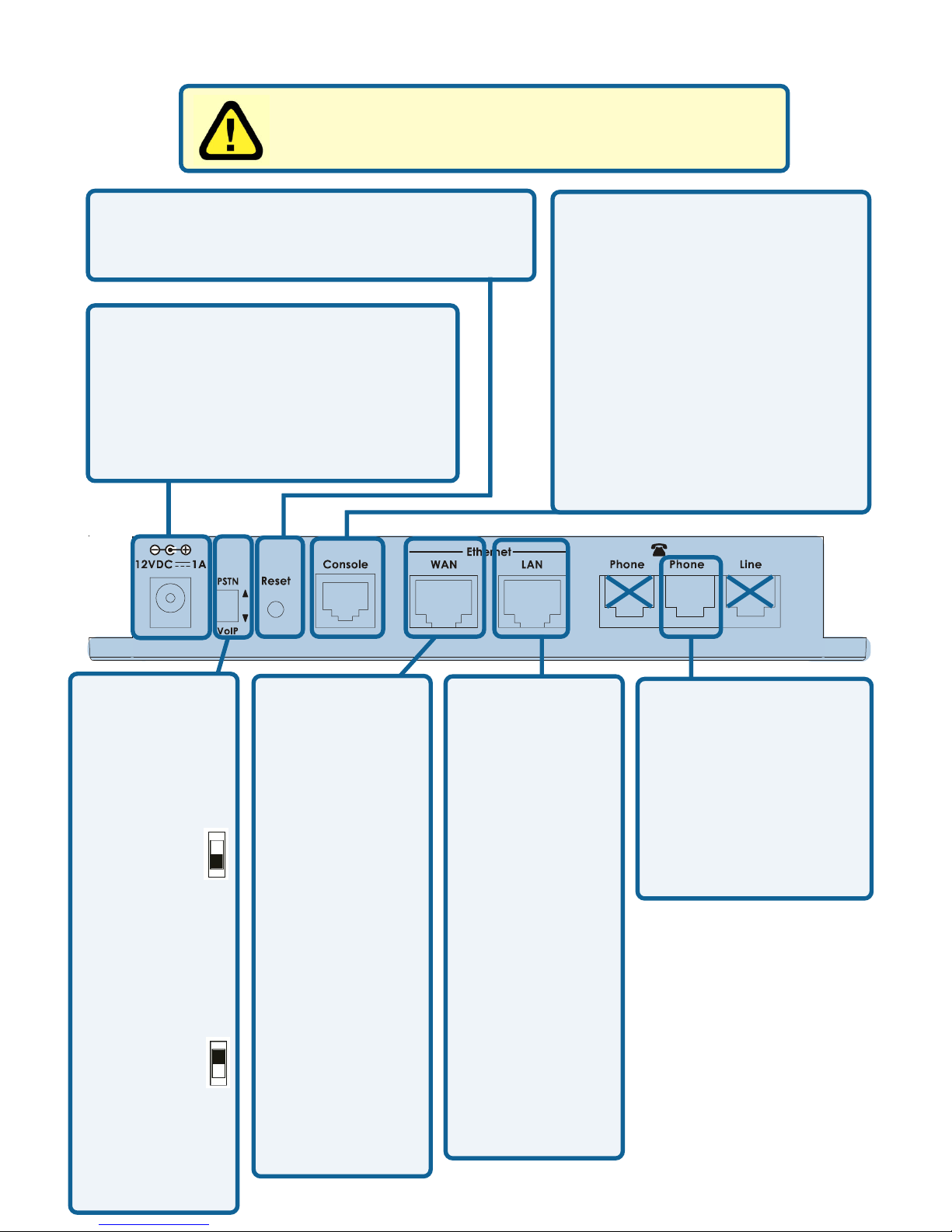
Connections
AC Power Connector Use the
included power adapter. If you use
a power adapter other than the
one included with the product you
will damage the device and void
the warranty on this product.
PSTN/VoIP
Switch to
select PSTN
or V oIP mode
When the
switch is in
the down
position,
Phone1/2 will
be in V oIP
Mode.
When the
switch is in
the up
position,
Phone1/2 will
be configured
to PSTN
Mode.
Reset Switch Used to return the device
to its original configuration. This is the
same as performing a factory reset.
Diagnostic Port An RJ-14
port used to configure the
device. (User needs a RJ14 to RS-232 converter).
Plug one end of a straightthrough wired RJ-14 cable
to the device and the other
end to a serial port of a PC
running a terminal
emulation program (such
as Microsoft HyperTerminal)
or a VT-100 terminal.
Phone 1
Normal RJ-11 phone
jack used to connect
to a telephone or fax
machine. Plug your
normal telephone or
fax machine directly
into this jack.
Ethernet WAN
A 10Mbps
Ethernet port
fitted with an
RJ-45
connector used
to connect the
V oIP gateway
to a W AN
device (e.g.
Cable/ADSL
Modem). This
port accepts
Category 3, 4
or 5 UTP
cabling with an
RJ-45
connector.
Ethernet LAN
A 10/100Mbps
dual-speed
Ethernet port
fitted with an
RJ-45
connector used
to connect the
V oIP gateway to
a LAN device
(hub, switch,
PC, etc.). This
port accepts
Category 5 or
better UTP
cabling with an
RJ-45
connector.
Warning! Using a different power adapter than the
one included with your purchase will damage the
DVG-1 120M and void the warranty .
21

6
One analog FXS interface port accepting an RJ-1 1 connector to facilitate
a V oIP connection
One 10Mbps W AN port for connecting to a DSL/Cable Modem or other
WAN devices
One 10/100Mbps LAN port for connecting to a local network
IP address assignment using DHCP (Dynamic Host Configuration
Protocol) or static configuration
IP Routing support (RIP1, RIP2 and S t atic Routing)
Remote software download/update
Supports IP sharing to allow multiple users to access the Internet via a
single IP address
Built-in PPPoE function to support dial-up connection for broadband
technology
Supports Caller ID
Supports QoS to guarantee voice quality
Automatic Call Redirection (ACR) function support
V oIP line automatic selection (e.g. 110, 119)
V oIP routing table support
Features & Benefit s
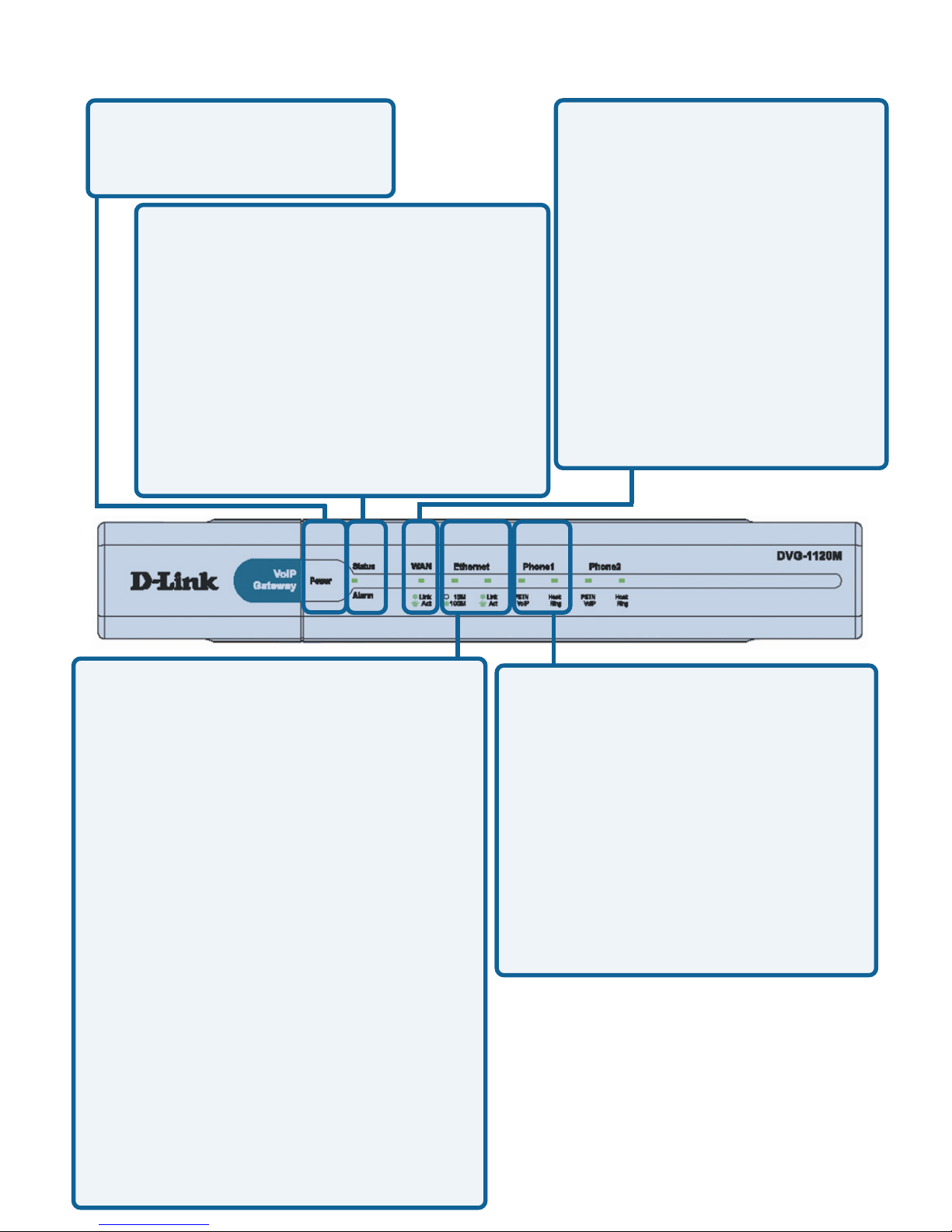
7
LEDS
Ethernet - This LED displays the
connection speed, link status, and
activity on the 10/100 dual-speed
Ethernet port that is used to connect
to your LAN.
10/100M - This indicator remains
unlit when there is no connection,
or the port is operating at 10Mbps
through a connection to a 10BASET device. It is lit when the port is
operating at 100Mbps through a
connection to a dual-speed or
100BASE-TX Fast Ethernet
device.
Link/Act - When a good link to a
powered-up but idle device is
detected on a port, this indicator
shines steadily . When packets are
received from the device, the
indicator blinks off and on.
WAN This LED displays the
link status and activity on the
10M Ethernet port that is used
to connect to your WAN
device (usually a Cable or
ADSL Modem). When a good
link to a powered-up but idle
device is detected on a port,
the WAN indicator shines
steadily. When packets are
received from the device, the
indicator blinks off and on.
Phone 1 - This LED displays the
activity on the RJ-11 port that is
used to connect to your normal
telephone/fax machine line.
Power This LED is lit when
the device is receiving
power; otherwise, it is unlit.
Status/Alarm
This LED will remain green when the
CPE is either performing a self-test or
booting up. The LED will flash green
slowly when the system is ready for a
connection with the Call Agent. It will
remain red when the self-test or
booting up is failed. It will flash red
slowly when the system is ready but
cannot receive an acknowledgment
from the Call Agent.
Hook/Ringing - When an offhook action is detected on a
phone port, this indicator shines
steadily . When a ringing signal
is received from the device, the
indicator blinks off and on.
8
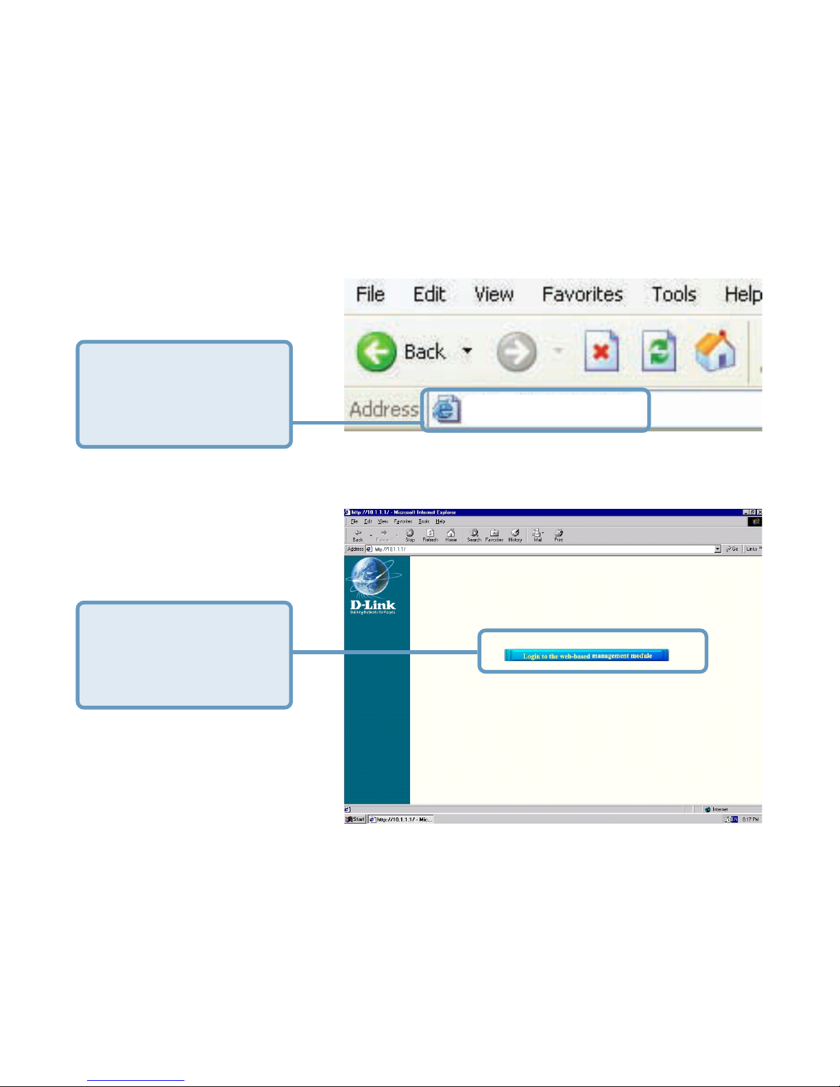
Web-based Management
In order to use a web browser to configure the VoIP gateway, you must make
sure it has a valid Ethernet connection to a PC or LAN via its LAN port.
Access the configuration utility to check the LAN port by entering the IP Address
into your web browser address field.
Click on Login to the
Web-based
Management
module
T ype 192.168.15.1
(the IP Address) into
the address field of
your browser.
http://192.168.15.1
9
Web-based Management (continued)
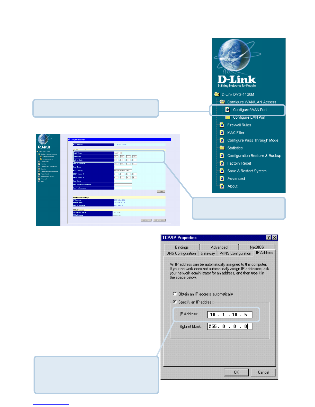
Setting Up the Connection
The V oIP gateway’s WAN port comes
with DHCP as default IP setting. If the
VoIP gateway cannot get the
assigned DHCP IP, it will use the
manual IP (default is 10.1.10.5 ) as
it’s default IP.
Click on Configure WAN Port.
T o configure the W AN port, please do the following:
Then go to Start>Control
Panel>Network
Connections>Right-click local
area connection >select
Properties> double click Internet
Protocol (TCP/IP). The screen at
right will appear.
Make sure the PC is in the same IP
domain as the VoIP gateway. You
can do this by changing the IP
address of the PC as shown here.
Manually input the
W AN IP Address here.
10
Web-based Management (continued)
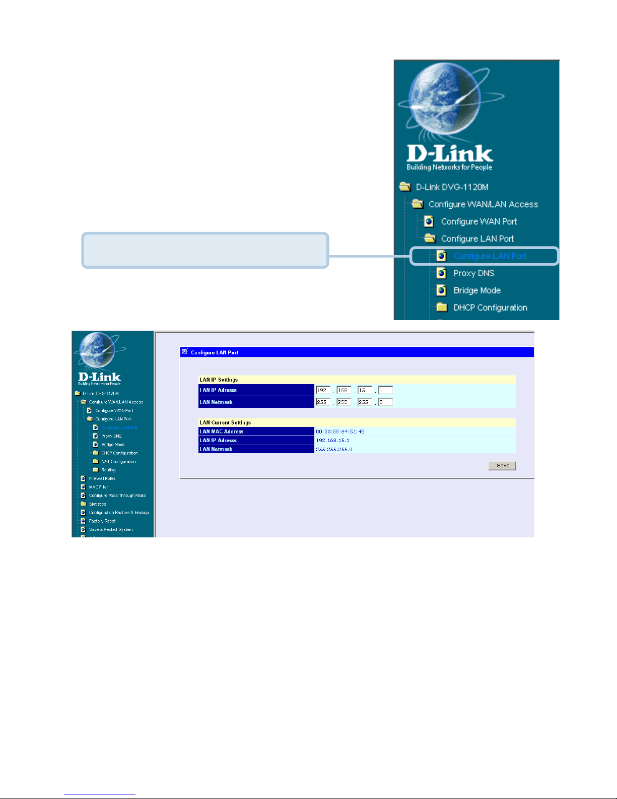
To configure the LAN port for the device, please do
the following:
After you have configured your W AN and LAN ports you can click on Save
and Restart System in the Configuration menu, or you can continue to
configure the V oIP. Af ter you have completed configuring the V oIP, you must
Save and Restart the System or your changes will not be saved.
In this configuration menu, users can configure the LAN IP Address.
(Recommended for advanced users.)
By default the LAN IP Address is: 192.168.15.1
Click on Configure LAN Port.
11
Web-based Management (continued)
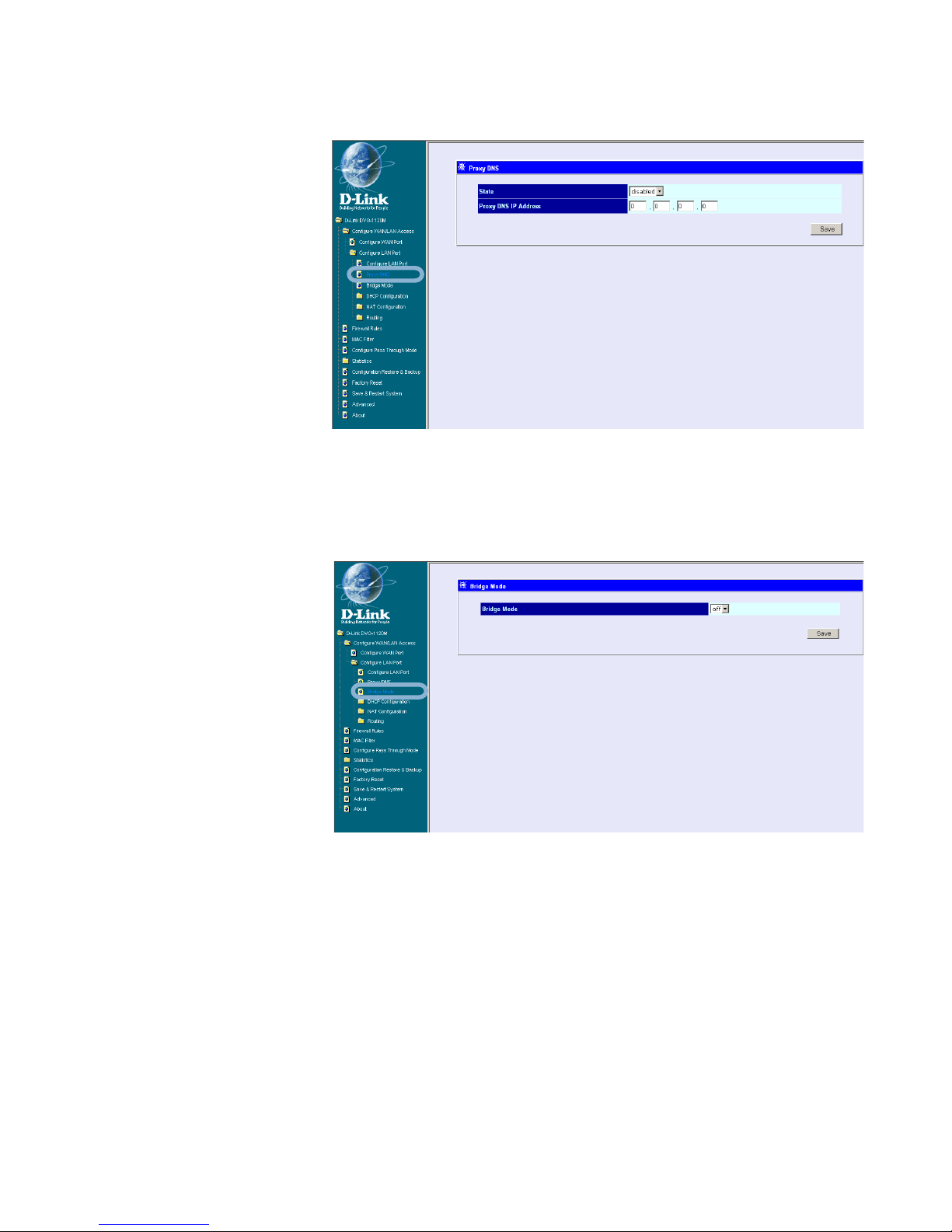
Configure LAN Port > Bridge Mode
State - This toggles
Enable and Disable for
the Proxy DNS
function.
Proxy DNS IP
Address - Enter the
Proxy DNS IP address
if instructed by your
service provider .
Configure LAN Port > Proxy DNS
Click Save to save the settings.
Bridge Mode - This
toggles On and Off to
turn NAT on or off for
Static Public IP
assignment.
Click Save to save the settings.
 Loading...