

D-LINK DSR-1000N User Manual [fr]

Building Networks for People
Quick Installation Guide
Unified Services Router
This document will guide you through the
basic installation process for your new
D-Link Wireless N Services Router.
DSR-500N / DSR-1000N
Quick Installation Guide
Installationsanleitung
Guide d’installation
Guía de instalación
Guida di Installazione
Documentation also available on
CD and via the D-Link Website
About This Guide
This guide gives step by step instructions for
setting up D-Link DSR-500N/1000N Wireless N
Services Router. Please note that the model you
ENGLISH
have purchased may appear slightly different from
those shown in the illustrations.
Unpacking the Product
Open the shipping carton and carefully unpack its
contents. Please consult the packing list located
in following information to make sure all items are
present and undamaged. If any item is missing
or damaged, please contact your local D-Link
reseller for replacement.
- One (1) DSR-500N/1000N Wireless N Services
Router Appliance.
- One (1) Power Cord
- One (1) Console Cable (RJ45-to-DB9 Cable)
- One (1) Ethernet (CAT5 UTP/Straight Through)
Cable
- One (1) Reference CD (CD-ROM containing
product documentation in PDF format)
- Two (2) Rack Mounting Brackets
- Three (3) Detachable Omni-direction antennas
Product Overview
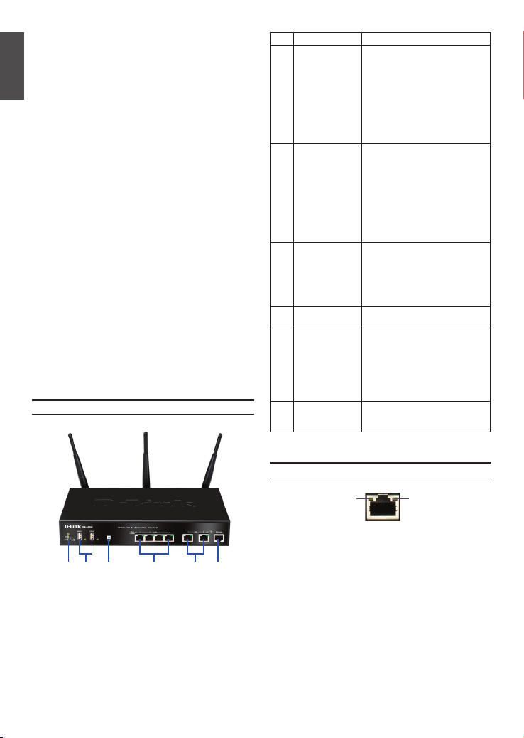
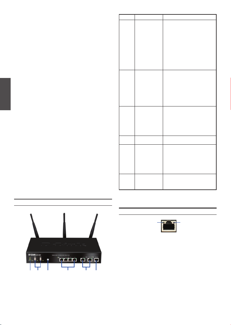
Front Panel - DSR-500N/1000N
Item Feature Description
A LED
(Top to bottom)
B USB Ports (2) It can support various USB 1.1 or
C WPS Button Wi-Fi Protected Setup (WPS)
D Gigabit LAN port
(1-4)
E Gigabit WAN port
(1-2)
F Console Port Used to access Command Line
Table 1. DSR-500N/1000N Front Panel Descriptions
Power LED: Indicates the Wireless N
Services Router is powered on.
5GHz WLAN LED (only available
on DSR-1000N): A solid light
indicates that the wireless segment
is ready. This LED blinks during
wireless data transmission.
2.4GHz WLAN LED: A solid light
indicates that the wireless segment
is ready. This LED blinks during
wireless data transmission.
2.0 devices below:
1. Flash Disk or Hard Disk for
network sharing.
2. 3G Adaptor for WAN redundant
(Available on DSR-1000N only)
3. WCN Conguration (It will be
supported by future rmware
upgrade)
4. Printer (It will be supported by
future rmware upgrade)
System is a simplied method for
securing your wireless network
during the “Initial setup” as well as
the “Add New Device” processes.
Please refer to the user manual for
more detail process.
Connect Ethernet devices, such as
computers, switches and hubs.
Two auto MDI/MDIX WAN ports
are the connection for the Ethernet
cable to the cable or DSL modem.
The WAN2 port is a congurable
port which can support WAN2 or
DMZ port for dual WAN connections or internal Server Farm
purpose.
Interface (CLI) via RJ45-to-DB9
console Cable.
FDA C EB
Figure 1. DSR-500N/1000N Front Panel
Note: DSR-500N supports one USB port only.
2 D-Link Wireless N Services Router
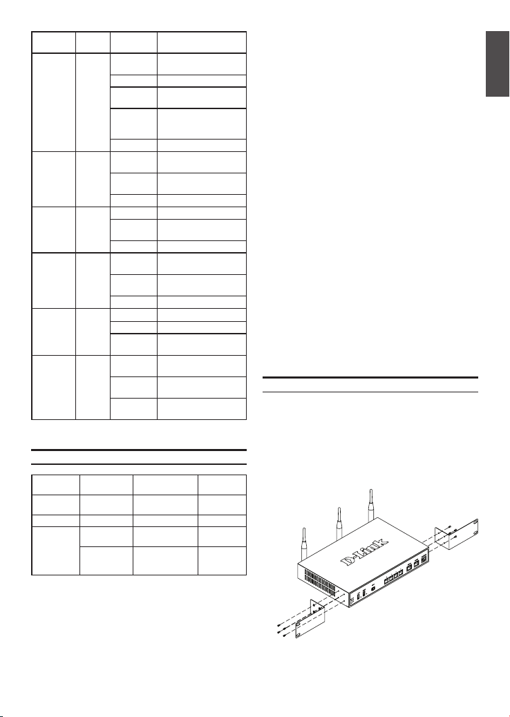
Device Status LEDs and Ethernet Port LEDs
Link
Speed
Figure 2. Ethernet RJ-45 Port LEDs
TX/RX
Status
The device LEDs show information about current
device status. When the device power up, the
POWER/STATUS LED will show solid orange
during power on process. Startup takes one minute
approximately to complete, the LED will change
to solid green. If you want to turn the device off
and on again, we recommend you wait a few
seconds between shutting it down and powering it
back. The Ethernet LEDs show the status of each
Ethernet port. Table 2 lists the name, color, status
and description of each device LED.
LED
Indicators
Power /
Status
2.4GHz/
5GHz
WLAN
USB Green Solid Green The link is good
WPS Blue Blinking
TX/RX
Status
LINK
Speed
Color Status Description
Orange/
Solid
Green
Orange
Solid Green Completion of power on
Blinking
Orange
Blinking
Green
Light Off The device is power-off
Green Steady
Green
Blinking
Green
Light Off No link
Blinking
Green
Light Off No link
Blue
Solid Blue The connection is
Light Off No Link.
Green Light Off No Link.
Solid Green Link present.
Blinking
Green
Green/
Light Off Port is operating at
Orange
Solid Green Port is operating at
Solid
Orange
Device during power-on
process
Device is crashed and
under recovery mode
The system is defective,
such rmware upgrades
fail.
The link is good
There is activity on
this port
There is activity on
this port
Start to process
successfully established
Port is sending or
receiving data.
10Mbps.
100Mbps
Port is operating at
1000Mbps
Table 2. Device Status LED Descriptions
DSR-500N/1000N Default Interface Settings
Ethernet
Interface Interface Type IP Address
LAN(1-4) /
WLAN
WAN1 DHCP Client 0.0.0.0/0 Disabled
WAN2
(Congurable
port)
Static IP 192.168.10.1/24 Enabled
DHCP Client
(default)
Static IP (When
it’s congured
as DMZ)
0.0.0.0/0 Disabled
172.17.100.254/24 Disabled
Table 3. Default Interface Settings
Web-Based
Management
Note: D-Link Wireless N Services Router only
allow Web GUI access from LAN and WLAN
interfaces by default for security reason.
The WAN2 is a congurable port which support
various and advanced scenario applications.
When WAN2 port is congured as DMZ port, the
IP address will be changed to 172.17.100.254.
Installing and Connection
This chapter describes how to install a
DSR-500N/1000N device in a standard 19-inch
equipment rack and how to connect cables and
power to the device.
Before You Begin
Observe the following precautions to help prevent
shutdowns, equipment failures and injuries:
- Before installation, always check that the power
supply is disconnected.
- Ensure that the room in which you operate the
device has adequate air circulation and that
the room temperature does Not exceed 40
o
(104
C)
- Allow 1 meter (3 feet) of clear space to the front
and back of the device.
- Do not place the device in an equipment rack
frame that blocks the air vents on the sides of
the chassis. Ensure that enclosed racks have
fans and louvered sides
- Correct these hazardous conditions before
any installation: moist or wet oors, leaks,
ungrounded or frayed power cables, or missing
safety grounds.
Installing Equipment
You can mount the DSR-500N/1000N device into
a standard 19-inch equipment rack. To install an
appliance into a rack:
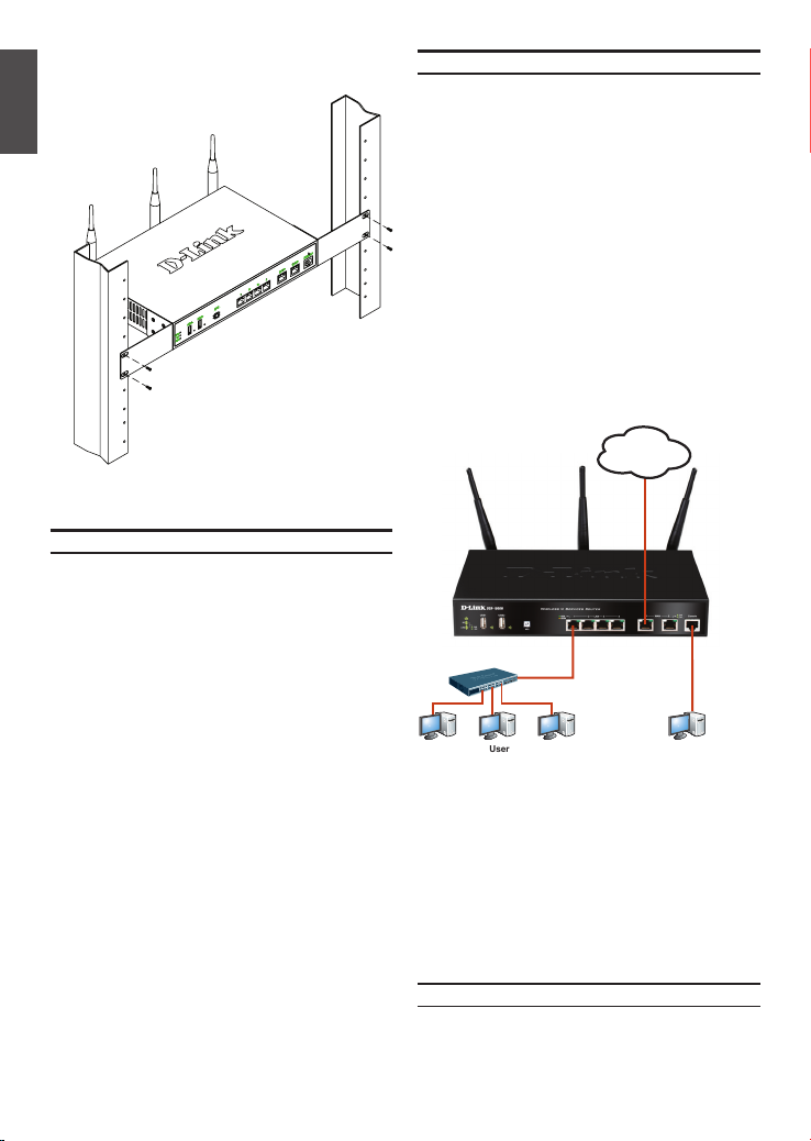
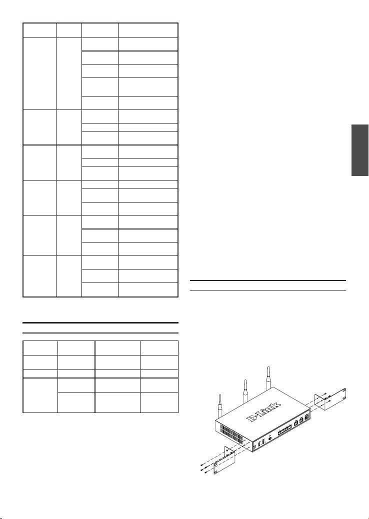
1. Attach the mounting brackets to each side of
the chassis as shown in gure 3 and secure
them with the screws provided.
Figure 3. Attaching Rack Mount Brackets
D-Link Wireless N Services Router 3
o
C
ENGLISH
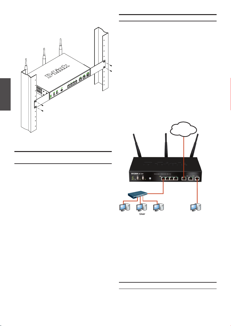
2. Then, use the screws provided with the
equipment rack to mount the device in the rack.
ENGLISH
Figure 4. Installing the Wireless N Services Router
in a standard-sized equipment rack
Connecting Power and Turning On/Off
The AC Power cord shipped with the device
connects the device to earth ground when plugged
an AC grounding-type power outlet. The device
must be connected to earth ground during normal
operation.
To connect power to the device, plug one end of
the AC power core into the AC power appliance
inlet on the back panel of the device. Plug the other
end into an AC power source.
Note: We recommend using a surge protector for
the power connection.
To power on the DSR-500N/1000N device, press
the AC power switch on the rear panel to the on
position. To power off the device, press the power
switch to the off position.
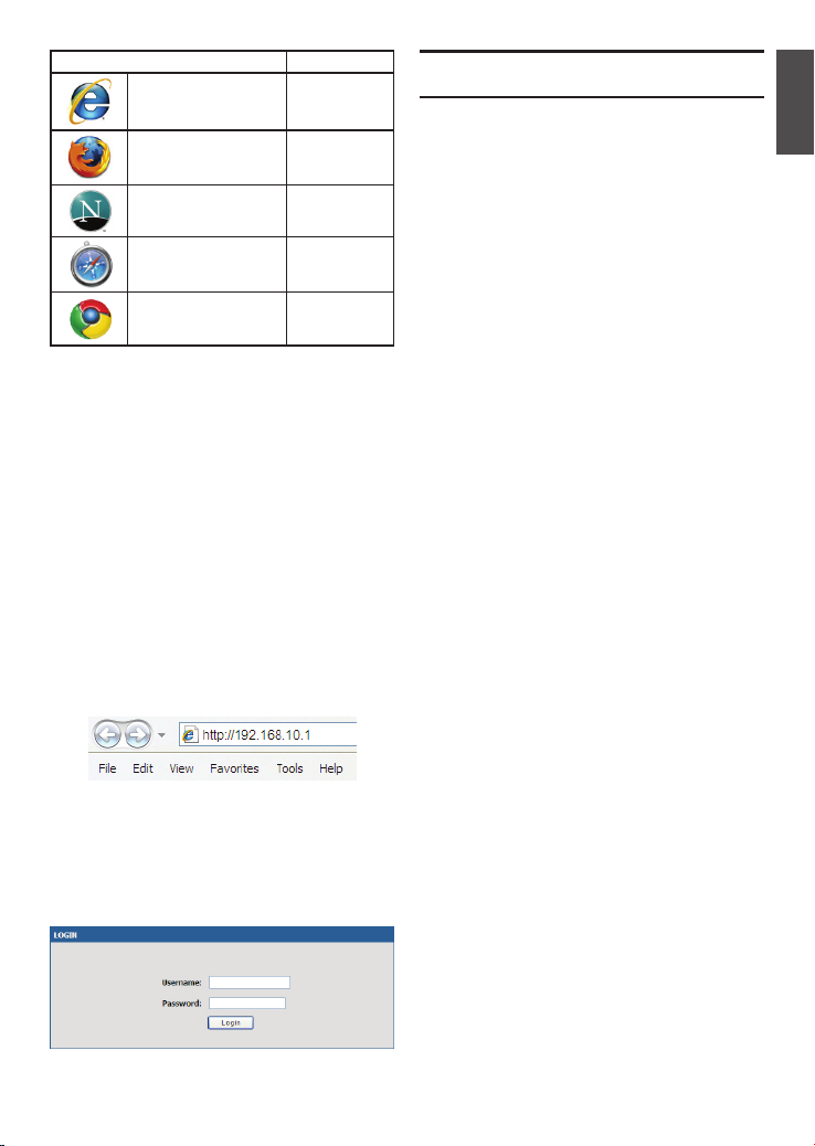
Connecting the Device to a Network
This section provides basic information about
physically connecting the DSR-500N / 1000N to
a network. To connect the necessary cables as
shown in Figure 5.
1. Connect an RJ-45 cable from the port
labeled WAN1 to the external router. The port
WAN1 is pre-allocated to the WAN1 network
segment.
2. Connect an RJ-45 cable from the port labeled
LAN (1-4) to a switch in the LAN network
segment.
3. Connect an RJ45-to-DB9 cable from the
console port for CLI (Command Line Interface)
management access.
Internet
WAN1
Switch
LAN Console
User
Figure 5. Basic Cabling Example
Initial Conguration
The Wireless N Services Router software is
preinstalled on the DSR-500N/1000N device.
When the device is powered on, it is ready to be
congured. While the device has a default factory
conguration that allow you to initially connect to
the device, you must perform further conguration
for your specic network requirements.
4 D-Link Wireless N Services Router
Using the WebUI
To use the WebUI, the workstation from which
you are managing the device must initially be on
the same subnetwork as the device.
Browser Version
Microsoft Internet
Explorer
Mozilla Firefox 3.5 or higher
Netscape Navigator 9.0 or higher
Apple Safari 4.0 and later
Google Chrome 3.0 and later
Table 4. Browser Compatibility
To access the device with the WebUI:
1. Connect your workstation on the port labeled
LAN (1-4), which is pre-allocated to the LAN.
2. Ensure your workstation is congured with a
static IP address in the 192.168.10.0/24
subnet.
Note: Disable pop-up blocking software or
add the management IP address
http://192.168.10.1 to your pop-up blocker’s
allow list.
3. Launch your browser; enter the IP address for
the LAN interface. (The factory default IP
address is http://192.168.10.1), then press Enter.
Figure 6. Browser Address
4. Log on the Wireless N Services Router Web
Interface The default log on information is:
Username: admin
Password: admin
Figure 7. Authentication Message
6.0 or higher
Using a Console Connection
(RJ45-to-DB9 DCE)
The Wireless N Services Router provides an serial
port that enables a connection to a computer or
terminal for monitoring and conguring the device.
This port is a RJ-45 connector, implemented as a
data communication terminal equipment (DCE)
connection.
To use the console port connection, you need the
following equipment:
1. A terminal or a computer with both a serial
port and the ability to emulate a terminal.
2. A RJ45-to-DB9 RS-232 with female connector.
(Already included in packing list)
3. If your Laptop or PC doesn’t have RS-232
connector, a converter is required.
Note: DSR-500N/1000N does not come with
RS-232 converter and these must be purchased
separately.
To establish a console connection:
1. Plug the RJ-45 connector of the supplied
RJ45-to-DB9 cable directly to the console port
on the Wireless N Services Router.
2. Connect the other end of the cable to a
terminal or to the serial connector of a
computer running terminal emulation software.
Set the terminal emulation software as
following:
Baud rate: 115200
Data bits: 8
Parity: None
Stop bits: 1
Flow control: None
3. When you have correctly set up the terminal,
having previously followed the instructions in
section 2.3, “Connecting Power and Turn the
Device On/Off” then switch on your device.
The boot sequence appears in the terminal.
4. Once the boot sequence completes, the
command prompt is displayed, the device is
ready to be congured.
ENGLISH
D-Link Wireless N Services Router 5

Finalizing the Conguration
After initial setup, you should refer to the
companion publications found in PDF format
on the accompanying master CD for more
ENGLISH
information on how to begin to congure the
DSR-500N/1000N device.
D-Link Wireless N Services Router User Manual
This document describes the general operation
and control of the Wireless N Services Router
rmware which drives and controls the Wireless
N Services Router series hardware. It includes
examples of how to carry out typical administrative tasks such as setting up a VPN and how to
use Wireless N Services Router series in various
scenarios.
D-Link Wireless N Services Router CLI
Reference Guide
This document describes all available text-based
commands that can be used on RJ45-to-DB9
Console or SSH interface to congure Wireless N
Services Router during system operation.
Additional Information
Additional help is available through D-Link
worldwide ofces listed at the appendix of the User
Manual or online. To know more about D-Link
security product products or marketing information,
please visit the website http://mydsr.dlink.com.
tw; for any support issue, please visit the website
http://support.dlink.com.tw, which will redirect
you to appropriate local D-Link website.
Technical Support
United Kingdom (Mon-Fri)
website: http://www.dlink.co.uk
FTP: ftp://ftp.dlink.co.uk
Home Wireless/Broadband 0871 873 3000
(9.00am–06.00pm, Sat 10.00am-02.00pm)
Managed, Smart, & Wireless Switches, or
Firewalls 0871 873 0909 (09.00am- 05.30pm)
(BT 10ppm, other carriers may vary.)
Ireland (Mon-Fri)
All Products 1890 886 899 (09.00am-06.00pm,
Sat 10.00am-02.00pm)
Phone rates: €0.05ppm peak, €0.045ppm off peak
times
6 D-Link Wireless N Services Router
Building Networks for People
Installationsanleitung
Unified Services Router
Diese Anleitung führt Sie durch den
allgemeinen Installationsprozess für Ihren
neuen D-Link Wireless N Services Router.
DSR-500N / DSR-1000N
Die Dokumentation ist auch auf CD und
über die D-Link-Website verfügbar
Informationen zum Handbuch
Diese Anleitung weist Sie Schritt für Schritt an, wie
Sie D-Link DSR-500N/1000N Wireless N Services
Router einrichten können. Beachten Sie, dass Ihr
Modell sich möglicherweise geringfügig von den
Abbildungen unterscheidet.
Lieferumfang und Auspacken
des Produkts
Öffnen Sie den Versandkarton, entnehmen Sie den
Inhalt und packen Sie ihn vorsichtig aus. Stellen
Sie bitte sicher, dass alle auf der Packliste aufgeführten Artikel auch tatsächlich geliefert wurden
und unbeschädigt sind. Sollte ein Artikel fehlen
oder beschädigt sein, wenden Sie sich zum Zwecke
einer Ersatzlieferung umgehend an Ihren D-Link-
DEUTSCH
Fachhändler.
- Ein (1) DSR-500N/1000N Wireless N Services
Router.
- Ein (1) Netzkabel
- Ein (1) Konsolenkabel (RJ45-to-DB9-Kabel)
- Ein (1) Ethernet-Kabel (CAT5 UTP/StraightThrough)
- Eine (1) Referenz-CD (CD-ROM mit der
Produktdokumentation im PDF-Format)
- Zwei (2) Rackbefestigungsklammern
- Drei (3) abnehmbare, allseitig bewegliche
Antennen
Produktübersicht
Vorderseite - DSR-500N/1000N
Element Merkmal Beschreibung
A LED
(Von oben nach
unten)
B USB-Ports (2) Kann verschiedene USB 1.1 oder 2.0
C WPS-Taste Das Wi-Fi Protected Setup
D Gigabit-LAN-Port
(1-4)
E Gigabit-WAN-Port
(1-2)
F Konsolenport Zum Zugriff auf CLI (Command Line
Tabelle 1. Beschreibung der Vorderseite des
LED-Betriebsanzeige: Zeigt an, dass
der Wireless N Services Router
eingeschaltet ist.
5 GHz WLAN LED (nur mit dem
DSR-1000N): Ein durchgehend
leuchtendes Licht zeigt an, dass das
drahtlose Segment betriebsbereit
ist. Diese LED blinkt während der
drahtlosen Datenübertragung.
2,4 GHz WLAN LED: Ein durchgehend
leuchtendes Licht zeigt an, dass das
drahtlose Segment betriebsbereit
ist. Diese LED blinkt während der
drahtlosen Datenübertragung.
Geräte (unten) unterstützen:
1. Flash-Speicher oder Festplatte für
gemeinsamen Netzwerkzugang.
2. 3G-Adaptor für redundantes WAN
(Nur mit dem DSR-1000N)
3. WCN-Konguration (Von zukünftigem Firmware-Upgrade unterstützt)
4. Drucker (Wird von zukünftigem
Firmware-Upgrade unterstützt)
(WPS)-System ist ein vereinfachtes
Verfahren zur Sicherung Ihres
drahtlosen Netzwerks beim 'Initial
setup' (Ersteinrichtung), sowie beim
Hinzufügen neuer Geräte. Weitere
Informationen dazu nden Sie im
Benutzerhandbuch.
Zum Anschluss von Ethernet-Geräten
wie Computer, Switches und Hubs.
Zwei Auto-MDI/MDIX-WAN-Ports sind
die Anschlüsse für das Ethernet-Kabel
an das Kabel- bzw. DSL-Modem.
Der WAN2-Port ist kongurierbar und
kann einen WAN2- oder DMZ-Port
für duale WAN-Verbindungen
unterstützen oder zu systeminternen
Serverfarm-Zwecken dienen.
Interface/Befehlszeilenschnittstelle)
über ein RJ45-to-DB9 Konsolenkabel.
DSR-500N/1000N
Gerätestatus-LEDs und Ethernet-Port-LEDs
FDA C EB
Abbildung 1. Die Vorderseite des DSR-500N/1000N
Hinweis: DSR-500N unterstützt nur einen
USB-Port.
8 D-Link Wireless N Services Router
Verbindungs-
geschwindigkeit
TX/RX-
Status
Abbildung 2. Ethernet RJ-45 Port LEDs
Die Geräte-LEDs zeigen Informationen über den
aktuellen Gerätestatus an. Die BETRIEBSANZEIGE/
STATUS-LED leuchtet während des Einschalt- und
Hochfahrvorgangs durchgehend orangefarben.
Der Vorgang dauert etwa eine Minute. Danach
leuchtet die LED durchgehend grün. Wenn Sie das
Gerät ausschalten und dann wieder einschalten
möchten, ist es ratsam, zwischen dem Ausschalten
und dem erneuten Einschalten ein paar Sekunden
zu warten. Die Ethernet-LEDs zeigen den Status
für jeden Ethernet-Port an. In Tabelle 2 sind Name,
Farbe, Status und Beschreibung für jede GeräteLED aufgeführt.
LED
Anzeigen
Strom /
Status
2,4 GHz/
5 GHz
WLAN
USB Grün Durchgehend
WPS Blau Blau blinkend Prozessstart
TX/RXStatus
Verbindungsgeschwindigkeit
Farbe Status Beschreibung
Orange-
Durchgehend
farben/
orangefarben
Grün
Durchgehend
grün
Blinkt orangefarben
Grün blinkend System defekt. Firmware-
LED leuchtet
nicht
Grün Durchgehend
grün
Grün blinkend Dieser Port ist aktiv
LED leuchtet
nicht
grün
Grün blinkend Dieser Port ist aktiv
LED leuchtet
nicht
Durchgehend
blau
LED leuchtet
nicht
Grün LED leuchtet
nicht
Durchgehend
grün
Grün blinkend Port sendet oder
Grün/
LED leuchtet
Orange-
nicht
farben
Durchgehend
grün
Durchgehend
orangefarben
Gerät während Einschaltund Hochfahrvorgang
Ende Hochfahrvorgang
Gerät abgestürzt und in
Wiederherstellmodus
Upgrades fehlgeschlagen.
Gerät ist ausgeschaltet.
Gute Verbindung
Keine Verbindung
Gute Verbindung
Keine Verbindung
Verbindung erfolgreich
hergestellt
Keine Verbindung
Keine Verbindung
Verbindung hergestellt
empfängt Daten
Port-Betrieb mit 10 Mbit/s
Port-Betrieb mit
100 Mbit/s
Port-Betrieb mit
1000 Mbit/s
Tabelle 2. Beschreibungen der Status-LEDs des Geräts
Standardeinstellungen für die DSR-500N/1000N-Schnittstellen
EthernetSchnittstelle
LAN (1-4) /
WLAN
WAN1 DHCP-Client 0.0.0.0/0 Deaktiviert
WAN2
(Kongurierbarer Port)
Schnittstellentyp IP-Adresse
Statische IP 192.168.10.1/24 Aktiviert
DHCP-Client
(Standard)
Statische IP
(wenn als DMZ
konguriert)
0.0.0.0/0 Deaktiviert
172.17.100.254/24 Deaktiviert
Webbasiertes
Management
Tabelle 3. Standardschnittstellen-Einstellungen
Hinweis: Standardmäßig ermöglichen D-Link
Wireless N Services Router aus Sicherheitsgründen
nur den webbasierten Zugriff über LAN- und WLANSchnittstellen.
WAN2 ist ein kongurierbarer Port. Er unterstützt
verschiedene und spezielle Anwendungsmöglichkeiten. Wird der WAN2-Port als DMZ-Port konguriert,
wird die IP-Adresse auf 172.17.100.254 geändert.
Installation und Verbindung
In diesem Abschnitt wird beschrieben, wie Sie ein
DSR-500N/1000N-Gerät in einem 19-ZollStandardrack installieren und Kabel am Gerät
anschließen.
Erste Schritte
Beachten Sie die folgenden Vorsichtsmaßnahmen,
um Fehler, Geräteausfälle und Verletzungen zu
vermeiden:
- Vor der Installation muss die Stromversorgung
getrennt werden.
- Das Gerät muss in einem Raum mit ausreichender
Belüftung betrieben werden. Die Raumtemperatur
o
darf 40
C
- Vor und hinter dem Gerät muss sich 1 Meter
freier Platz benden.
- Achten Sie beim Installieren des Geräts in einem
Rackrahmen darauf, dass die Lüftungsöffnungen
an den Seiten des Gehäuses nicht blockiert
sind. Stellen Sie sicher, dass geschlossene
Racks über Lüfter und seitliche Lüftungsschlitze
verfügen.
- Beseitigen Sie vor der Installation die folgenden
Gefahrenquellen: feuchte oder nasse Böden,
Lecks, beschädigte oder nicht geerdete Stromkabel und fehlende Sicherheitserdungen.
Installation des Geräts
Das DSR-500N/1000N-Gerät kann in ein Geräterack
mit einer Standardgröße von 19 Zoll eingebaut
werden. So installieren Sie ein Gerät in einem Rack:
1. Bringen Sie die Befestigungsklammern an den
beiden Seiten des Gehäuses an, wie in
Abbildung 3 gezeigt, und xieren Sie sie mit
den mitgelieferten Schrauben.
Abbildung 3. Anbringen der Rackbefestigungsklammern
D-Link Wireless N Services Router 9
DEUTSCH
2. Befestigen Sie dann das Gerät mithilfe der mit
dem Rack gelieferten Schrauben im Geräterack.
DEUTSCH
Abbildung 4. Installation des Wireless N Services Routers
in einem Geräterack mit Standardgröße
Herstellen der Stromversorgung und
Ein-/Ausschalten
Das mit dem Gerät gelieferte Netzkabel verbindet
das Gerät mit Masse, wenn es an eine SchukoNetzsteckdose angeschlossen wird. Während des
normalen Betriebs muss das Gerät mit Masse
verbunden sein.
Zur Stromversorgung des Geräts stecken Sie ein
Ende des Netzkabels in den Netzstromeingang an
der Geräterückseite und schließen Sie das andere
Ende an eine Wechselstromquelle an.
Hinweis: D-Link empehlt die Verwendung eines
Überspannungsschutzes für die Stromverbindung.
Zum Einschalten des DSR-500N/1000N-Geräts
stellen Sie den Netzschalter an der Geräterückseite
in die Position EIN. Zum Ausschalten des Geräts
stellen Sie den Netzschalter in die Position AUS.
10 D-Link Wireless N Services Router
Anschließen des Geräts an ein Netzwerk
In diesem Abschnitt wird der physische Anschluss
des DSR-500N / 1000N an ein Netzwerk
beschrieben. Zum Anschluss der erforderlichen
Kabel wie in Abbildung 5 angezeigt:
1. Verbinden Sie Port WAN1 mithilfe eines RJ-45Kabels mit dem externen Router. Port-Nr.
WAN1 ist standardmäßig dem WAN1-Netzwerksegment zugewiesen.
2. Verbinden Sie den LAN-Port (1-4) mithilfe
eines RJ-45-Kabels mit einem Switch im
LAN-Netzwerksegment.
3. Verbinden Sie den Konsolenport mit einem
RJ45-to-DB9-Kabel, um die Verwaltung über
die CLI (Command Line Interface, Befehlszeilenschnittstelle) zu ermöglichen.
Internet
WAN1
Switch
Abbildung 5. Einfaches Verkabelungsbeispiel
LAN Console
User
Erstkonguration
Die Wireless N Services Router-Software ist auf
dem DSR-500N/1000N-Gerät vorinstalliert. Sobald
das Gerät eingeschaltet ist, kann es konguriert
werden. Obwohl das Gerät eine werkseitige
Standardkonguration aufweist, mit der Sie eine
Erstverbindung zum Gerät herstellen können,
müssen Sie weitere Einstellungen für Ihre besonderen Netzwerkanforderungen vornehmen.
Die Weboberäche (WebUI)
Damit Sie die WebUI verwenden können, muss der
Arbeitsplatzrechner, mit dem das Gerät verwaltet
wird, sich zunächst im selben Subnetzwerk wie das
Gerät benden.
 Loading...