

Page 1
Quick Installation Guide
Switch
This document will guide you
through the basic installation
process for your new D-Link
Power over Ethernet Switch
DGS-1008MP
QUICK INSTALLATION GUIDE
INSTALLATIONSANLEITUNG
GUIDE D’INSTALLATION
GUÍA DE INSTALACIÓN
GUIDA DI INSTALLAZIONE
Documentation is also available on the D-Link website
Page 2
About This Guide
The D-Link DGS-1008MP Power over Ethernet
Gigabit Desktop Switch is a stand-alone plug-andplay device. This Quick Installation Guide gives
step-by-step instructions for setting up the device.
The model you have purchased may appear slightly
different from the images shown in this guide. For
ENGLISH
more detailed information about the switch, installation
process, making network connections, and technical
specications, please refer to the User Manual or visit
http://www.dlink.com
Package Contents
These are the items included with your purchase:
• 8-Port DGS-1008MP Gigabit Ethernet PoE
Switch
• Quick Installation Guide
• AC power cord
• Four rubber feet
• Screws and two mounting brackets
If any of the above items are missing, please contact
your reseller.
Installation Guidelines
As with any electronic device, you should place the
equipment where it will not be subjected to extreme
temperatures or humidity, vibration, dust, direct
sunlight, or electromagnetic interference. Specically,
the site you select should meet the following
requirements:
A. Install the DGS-1008MP in a cool and dry place.
The ambient temperature should be between
0 and 40 degrees Celsius (32 to 104 degrees
Fahrenheit). The relative humidity should be less
than 90 percent, non-condensing.
B. Install the switch in a site free from a strong
electromagnetic source. Surrounding electrical
devices should not exceed the electromagnetic
eld (RFC) standards for IEC 801-3, Level 2 (3
V/M) eld strength.
C. Make sure that the equipment receives adequate
ventilation. Leave at least 10 cm of space at
the left and right-hand side of the switch for
ventilation. Do not block the ventilation holes on
either side of the switch.
D. The power outlet should be within 1.2 meters of
the device.
E. Do not stack any device on top of the switch.
22
Switch Installation
The DGS-1008MP can easily be mounted in an EIA
standard size 19-inch rack which can be placed in
a wiring closet with other equipment or placed on a
desktop or shelf.
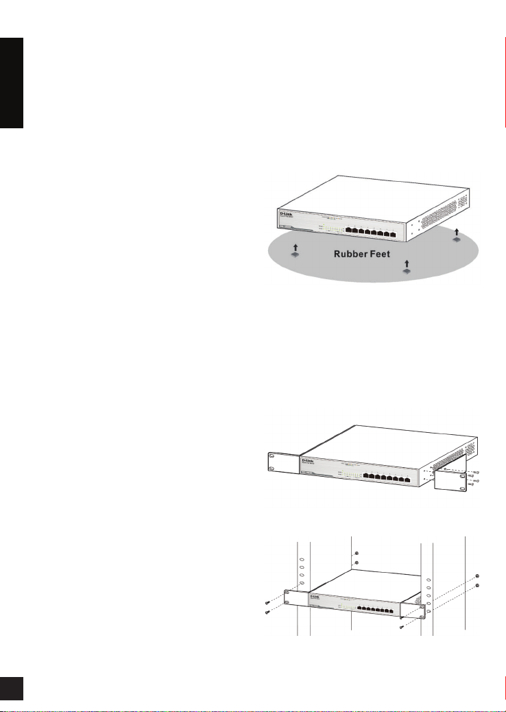
Desktop or Shelf Installation
When installing the switch on a desktop or shelf, use
the rubber feet provided. Position and apply the rubber
feet to the bottom corners of the DGS-1008MP switch.
Figure 1 - Attach rubber feet
Rack Installation
To install in a rack, attach the mounting brackets
to the switch’s side panels (one on each side) and
secure them with the screws provided. Then, use the
hardware provided with the equipment rack to mount
the switch in the rack.
Figure 2 - Attach mounting brackets
Figure 3 - Mount switch in rack
Page 3
Setting up the DGS-1008MP
PoE Switch
This switch is a plug-and-play device.
1. Plug the AC power cord into a free wall socket,
then plug the other end of the power connector
into the DGS-1008MP. The Power LED will
illuminate conrming that the device has powered
up successfully.
2. Insert Ethernet cables with an RJ45 connector to
the 10/100/1000 Base-T PoE Ethernet port.
3. These ports also support automatic MDI/MDIX
crossover, eliminating the need for crossover
cables or uplink ports. Each port can be
connected directly to a server, hub, router, or
switch using regular straight-through twisted-pair
Ethernet cables.
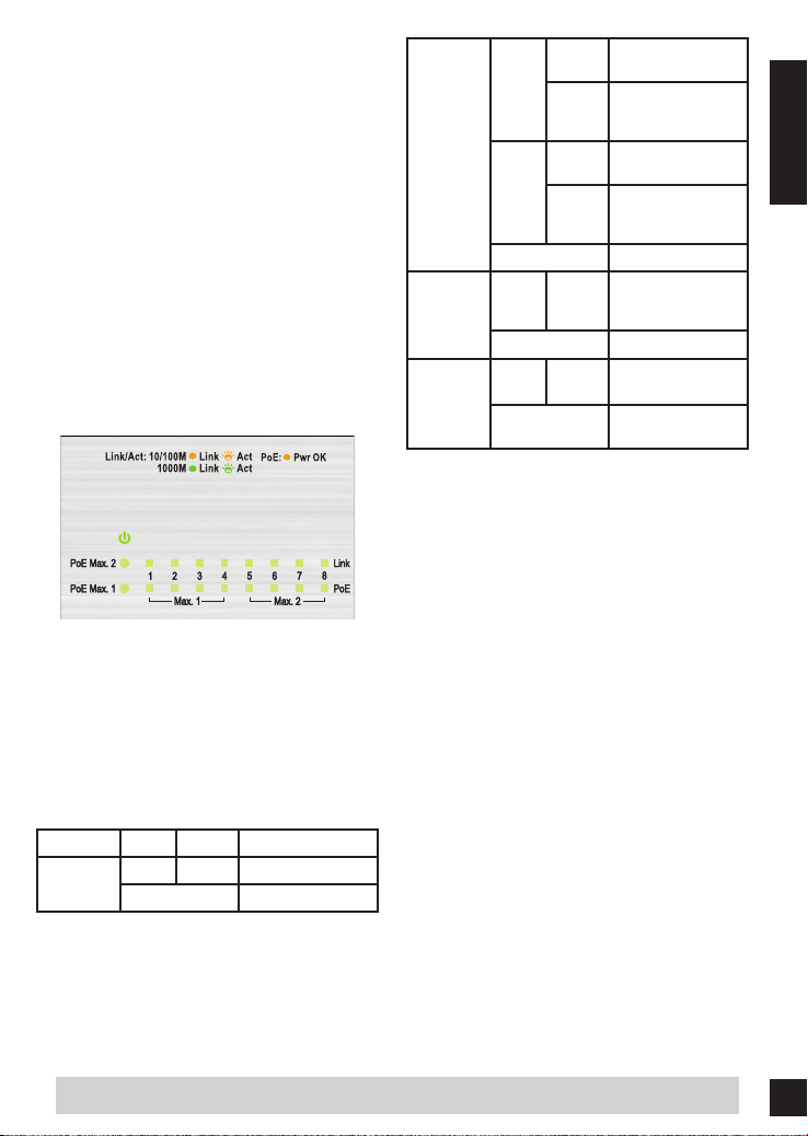
Figure 4 - LED indicators
LED Indicators
The LED indicators allow you to monitor, diagnose,
and troubleshoot any potential problem within the
switch, connection, or attached devices.
Connection at
1000 Mbps
Reception or
Transmission at
1000 Mbps
Connection at
10/100 Mbps
Reception or
Transmission at
10/100 Mbps
PoE device
connected and
receiving power
PoE device load over
budget
PoE device load
within limit
Link
(Port 1-8)
PoE
(Port 1-8)
PoE Max 1
(Port 1-4)
PoE Max 2
(Port 5-8)
On
Green
Blinking
On
Amber
Blinking
Off No Link
Amber On
Off No PoE device
Amber On
Off
Troubleshooting
1. What should I do if a connected device is not
detected?
• Ensure the port LED is illuminated or
ashing. If not, try using a new LAN cable or
power cycling the switch.
2. What should I do if a PoE device is not powered
by the DGS-1008MP?
• Ensure that the total device load does not
exceed the maximum power budget of
140 watts.
ENGLISH
LED Color State Indication
Power
Green On Power on
Off Power off
TECHNICAL SUPPORT
dlink.com/support
33
Page 4
Informationen zu dieser
Anleitung
Bei dem DGS-1008MP Power over Ethernet
Gigabit Desktop Switch von D-Link handelt es
sich um ein eigenständiges Plug-and-Play-Gerät.
Diese Installationsanleitung weist Sie Schritt für
Schritt an, wie Sie das Gerät einrichten. Das von
Ihnen erworbene Modell kann sich möglicherweise
geringfügig von den Abbildungen in dieser Anleitung
unterscheiden. Ausführlichere Informationen zu dem
Switch, dem Installationsvorgang, der Herstellung
von Netzwerkverbindungen sowie technische Daten
nden Sie im Benutzerhandbuch oder im Internet
unter:http://www.dlink.com
Packungsinhalt
Im Lieferumfang des Produkts enthalten sind:
• 8-Port DGS-1008MP Gigabit Ethernet PoE
Switch
• Installationsanleitung
• Netzkabel
• Vier Gummistützfüße
• Schrauben und zwei Einbauwinkel
Sollte einer der oben aufgeführten Artikel fehlen,
wenden Sie sich bitte an Ihren Fachhändler.
Leitlinien zur Installation
Achten Sie wie bei jedem elektronischen Gerät
darauf, das Gerät keinen extremen Temperaturen
oder Feuchtigkeit, Vibrationen, Staub, direktem
Sonnenlicht oder elektromagnetischen Interferenzen
auszusetzen. Der Standort, den Sie für das Gerät
wählen, sollte deshalb unbedingt die folgenden
Anforderungen erfüllen:
A. Installieren Sie den DGS-1008MP an
einem kühlen und trockenen Ort. Die
Umgebungstemperatur sollte zwischen 0 und 40
Grad Celsius sein. Die relative Feuchtigkeit sollte
unter 90 %, nicht kondensierend, sein.
B. Installieren Sie den Switch an einem Ort, an
dem er keiner starken elektromagnetischen
Quelle ausgesetzt ist. Elektrogeräte in der
Nähe sollten die elektromagnetische Feldstärke
(RFC) der Stufe 2 nach IEC 801-3 (3 V/M) nicht
überschreiten.
C. Sorgen Sie für eine ausreichende Belüftung des
Geräts. Lassen Sie mindestens 10 cm Platz an
der linken und rechten Seite des Switches, um
44
Luftbewegung zu gewährleisten. Blockieren Sie
nicht die Lüftungsöffnungen auf beiden Seiten
des Switches.
D. Die Steckdose sollte nicht weiter als 1,2 Meter
vom Gerät entfernt sein.
E. Stellen Sie keine weiteren Geräte auf den Switch.
Installation des Switch
Der DGS-1008MP kann problemlos in einen dem
EIA-Standard entsprechenden 19-Zoll Rack installiert
und dieser zusammen mit anderen Geräten in einem
Verteilerschrank eingesetzt werden oder auf einen
Schreibtisch oder ein Regal gestellt werden.
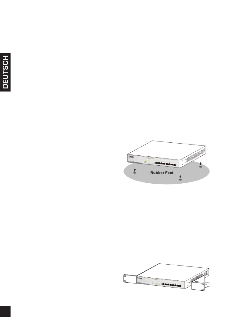
Installation auf einem
Schreibtisch oder Regal
Bei der Installation des Switch auf einem Schreibtisch
oder einem Regal verwenden Sie bitte die
mitgelieferten Gummistützfüße. Bringen Sie sie an
den Ecken auf der Unterseite des DGS-1008MP
Switch an.
Abbildung 1 - Anbringen der Gummistützfüße
Installation in einem Rack
Bringen Sie zur Installation des Geräts in einem Rack
die Einbauwinkel
an den jeweiligen Seitenverkleidungen des Switches
an und
befestigen Sie sie mit den mitgelieferten Schrauben.
Verwenden Sie dann
das mit dem Rack gelieferten Zubehör, um
den Switch im Rack anzubringen.
Abbildung 2 - Anbringen der Einbauwinkel
Page 5

Abbildung 3 - Montage des Switches im Rack
Einrichten des DGS-1008MP
PoE Switch
Dieser Switch ist ein Plug-and-Play-Gerät.
1. Stecken Sie den Gerätestecker des Netzkabels
in die Stromeingangsbuchse des DGS-1008MP
und setzen Sie den Netzstecker in eine freie
Wandsteckdose. Die LED-Betriebsanzeige
(oder Stromanzeige) leuchtet auf. Das zeigt,
dass das Gerät erfolgreich eingeschaltet und
hochgefahren ist.
2. Stecken Sie Ethernet-Kabel mit RJ45-
Steckverbindern in die 10/100/1000 Base-T PoE
Ethernet-Ports.
3. Diese Ports unterstützen auch automatisches
MDI/MDIX-Uplink, was die Verwendung von
gekreuzten Kabeln oder Uplink-Ports unnötig
macht. Jeder Port kann direkt an einen
Server, Hub, Router oder Switch mithilfe eines
gewöhnlichen 1:1 Twisted-Pair Ethernet-Kabels
angeschlossen werden.
Abbildung 4 - LED-Anzeigen
diagnostizieren und eventuell beheben.
LED Farbe Zustand Information
Strom
Verbindung
(Port 1-8)
PoE
(Port 1-8)
PoE Max 1
(Port 1-4)
PoE Max 2
(Port 5-8)
Grün Ein Strom ein
Aus Strom aus
Ein
Grün
Blinkt
Ein
Gelb
Blinkt
Aus Keine Verbindung
Gelb Ein
Aus Kein PoE-Gerät
Gelb Ein
Aus
Verbindung mit
1000 Mbit/s
Datenempfang oder
-übertragung mit
1000 Mbit/s
Verbindung mit
10/100 Mbit/s
Datenempfang oder
-übertragung mit
10/100 Mbit/s
PoE-Gerät
angeschlossen und
empfängt Strom
PoE-Gerätbelastung
über Leistungsbudget
PoE-Gerätbelastung
im Leistungslimit
Fehlerbehebung
1. Was soll ich tun, wenn ein angeschlossenes
Gerät nicht erkannt wird?
• Vergewissern Sie sich, dass die Port LED
leuchtet oder blinkt. Ist das nicht der Fall,
verwenden Sie ein neues LAN-Kabel oder
schalten Sie den Switch aus und wieder ein.
2. Was soll ich tun, wenn ein PoE-Gerät nicht von
dem DGS-1008MP mit Strom versorgt wird?
• Stellen Sie sicher, dass die
Gerätegesamtbelastung nicht das maximale
Leistungsbudget von 140 Watt überschreitet.
LED-Anzeigen
Über die LED-Anzeigen können Sie jedes potentielle
Problem mit dem Switch, der Verbindung oder
mit angeschlossenen Geräten überwachen,
TECHNISCHE UNTERSTÜTZUNG
dlink.com/support
55
Page 6

À propos de ce guide
Le commutateur Gigabit PoE pour ordinateur de
bureau DGS-1008MP de D-Link est un périphérique
autonome plug-and-play. Ce guide d'installation rapide
fournit des instructions qui vous aideront à congurer
votre périphérique étape par étape. L'apparence du
modèle que vous avez acheté peut différer légèrement
des images présentées dans ce guide. Pour de
plus amples informations sur le commutateur, son
processus d’installation, sa connexion au réseau et
ses caractéristiques techniques, veuillez consulter le
manuel d'utilisation ou visiter le site
http://www.dlink.com
Contenu de la boîte
Votre achat comprend les éléments suivants :
• Commutateur Gigabit Ethernet PoE 8 ports
DGS-1008MP
• Guide d'installation rapide
• Cordon d'alimentation CA
• Quatre pieds en caoutchouc
• Vis et deux supports de montage
Contactez avec votre revendeur s'il manque l'un des
éléments ci-dessus.
Directives d'installation
Comme tout dispositif électronique, vous devez
placer l'appareil dans un lieu où il n'est pas soumis
à des températures ou une humidité extrêmes,
des vibrations, de la poussière, la lumière directe
du soleil ou des interférences électromagnétiques.
Plus précisément, le site que vous sélectionnez doit
répondre aux exigences suivantes :
A. Installez le DGS-1008MP dans un endroit frais et
sec. La température ambiante doit se situer entre
0 et 40 degrés Celsius. L'humidité relative doit être
inférieure à 90 pourcent, sans condensation.
B. Installez le commutateur dans un endroit exempt
de sources de fort champ électromagnétique. Les
dispositifs électriques situés à proximité ne doivent
pas dépasser les normes relatives au champ
électromagnétique (RFC) en termes de puissance
de champ, à savoir le niveau 2 (3 V/M) selon la
norme IEC 801.3.
C. Vériez que l'équipement est correctement aéré.
Laissez au moins 10 cm à gauche et à droite
du commutateur pour en garantir la ventilation.
N'obstruez pas les orices de ventilation situés de
chaque côté.
66
D. La prise de courant doit être à moins de 1,2 mètres du
périphérique.
E. N'empilez pas de dispositifs sur le commutateur.
Installation du commutateur
Le DGS-1008MP s'installe facilement dans un bâti EIA de
taille standard (48,26 cm), qui peut être placé dans une
armoire de répartition avec un autre équipement ou sur un
bureau ou une étagère.
Installation sur un bureau ou
une étagère
Si vous installez le commutateur sur un bureau ou une
étagère, utilisez les pieds en caoutchouc fournis. Placez
et collez les pieds en caoutchouc sous les coins inférieurs
du commutateur DGS-1008MP.
Figure 1 - Fixation des pieds en caoutchouc
Installation dans un bâti
Pour installer dans un bâti, xez les pattes de montage
sur les panneaux latéraux du commutateur (de chaque
côté) et serrez-les avec les vis fournies. Ensuite, utilisez le
matériel fourni avec le bâti pour monter
le commutateur dans celui-ci.
Figure 2 - Fixation des supports de montage
Figure 3 - Montage du commutateur dans le bâti
Page 7

Conguration du
commutateur PoE DGS1008MP
Ce commutateur est un périphérique plug-and-play.
1. Branchez le cordon d'alimentation CA dans une
prise murale libre, puis branchez l'autre extrémité
du connecteur d'alimentation du DGS-1008MP. Le
voyant d'alimentation s'allume pour conrmer que le
dispositif a été correctement mis sous tension.
2. Insérez les câbles Ethernet équipés d'un connecteur
RJ45 dans le port Ethernet PoE 10/100/1000 Base-T.
3. Ces ports prennent en charge la détection
automatique MDI/MDIX de câble croisé, éliminant le
besoin de câbles croisés ou de ports de connexion
montante. Chaque port peut être directement
connecté à un serveur, un concentrateur, un routeur,
ou un commutateur en utilisant des câbles Ethernet
droits à paires torsadées ordinaires.
Figure 4 - Voyants lumineux
Voyants lumineux
Les voyants lumineux vous permettent de contrôler,
diagnostiquer, et dépanner tout problème qui pourrait
survenir dans le commutateur, la connexion, ou les
dispositifs connectés.
Voyant Couleur État Indication
Alimentation
Vert Allumé Allumé
Éteint Non alimenté
Connexion à
1000 Mbits/s
Réception ou
transmission à
1000 Mbits/s
Connexion à
10/100 Mbits/s
Réception ou
transmission à
10/100 Mbits/s
Périphérique PoE
connecté et sous
tension
Aucun périphérique
PoE
Charge du
périphérique PoE
au-dessus du budget
Charge du
périphérique PoE dans
la limite
Connexion
(Port 1-8)
PoE
(Port 1-8)
PoE Max 1
(Port 1-4)
PoE Max 2
(Port 5-8)
Allumé
Vert
Clignotant
Allumé
Orange
Clignotant
Désactivée Pas de connexion
Orange Activé
Désactivé
Orange Activé
Désactivé
Résolution des problèmes
1. Que dois-je faire si un périphérique connecté n'est
pas détecté ?
• Assurez-vous que le voyant lumineux du port
est allumé ou clignote. Sinon, essayez d'utiliser
un nouveau câble de réseau local ou de
redémarrer le commutateur.
2. Que dois-je faire si un périphérique PoE n'est pas
alimenté par le DGS-1008MP ?
• Assurez-vous que la charge totale du
périphérique ne dépasse pas le budget de
puissance maximum de 140 watts.
ASSISTANCE TECHNIQUE
dlink.com/support
77
Page 8

Acerca de esta guía
El conmutador de escritorio Gigabit con alimentación
a través de Ethernet DGS-1008MP de D-Link es un
dispositivo plug-and-play independiente. Esta Guía
de instalación rápida proporciona instrucciones paso
a paso para congurar el dispositivo. El modelo que
ha adquirido puede tener un aspecto ligeramente
diferente al de las imágenes mostradas en esta guía.
Para obtener información más detallada acerca del
conmutador, el proceso de instalación, la realización
de conexiones de red y las especicaciones técnicas,
consulte el manual del usuario o visite
http://www.dlink.com
¿Qué contiene la caja?
Estos son los elementos incluidos con el equipo que
ha adquirido:
• 8-Port DGS-1008MP Gigabit Ethernet PoE
Switch
• Guía de instalación rápida
• Cable de alimentación de CA
• Cuatro patas de goma
• Tornillos y dos soportes de montaje
Si falta cualquiera de los componentes anteriores,
póngase en contacto con el proveedor.
Directrices de la instalación
Como con cualquier dispositivo electrónico, debe
colocar el equipo en un lugar en el que no esté sujeto a
temperaturas extremas o humedad, vibración, polvo,
luz solar directa o interferencias electromagnéticas.
Especícamente, el lugar que seleccione debe
cumplir los requisitos siguientes:
A. Instale el DGS-1008MP en un lugar fresco y seco.
La temperatura ambiente debe estar entre 0 y 40
grados Celsius (de 32 a 104 grados Fahrenheit).
La humedad relativa debe ser inferior al 90 por
ciento, sin condensación.
B. Instale el conmutador en un lugar en el que
no existan fuentes electromagnéticas fuertes.
Los dispositivos eléctricos circundantes no
deben superar los estándares sobre campos
electromagnéticos de la norma IEC 801-3,
intensidad de campo de nivel 2 (3 V/M).
C. Asegúrese de que el equipo recibe la ventilación
adecuada. Deje al menos un espacio de 10 cm libre
en el lateral izquierdo y derecho del conmutador
para ventilación. No bloquee los oricios de
ventilación a ambos lados del conmutador.
88
D. La toma de alimentación debe estar a una distancia
máxima de 1,2 metros del dispositivo.
E. No apile ningún dispositivo encima del conmutador.
Instalación del conmutador
El DGS-1008MP se puede montar fácilmente en un
estante de 19 pulgadas para EIA de tamaño estándar,
que se puede colocar en un armario de conexiones
junto con otros equipos o en un escritorio o estante.
Instalación en escritorio o
estante
Al instalar el conmutador en un escritorio o estante,
utilice las patas de goma suministradas. Coloque y
aplique las patas de goma en las esquinas inferiores
del conmutador DGS-1008MP.
Figura 1 - Acople las patas de goma
Instalación en bastidor
Para instalar en un bastidor, acople los soportes
de montaje a los paneles laterales del conmutador
(uno a cado lado) y asegúrelos con los tornillos
suministrados. A continuación, utilice el hardware
suministrado con el bastidor del equipo para montar
el conmutador en el bastidor.
Figura 2 - Acoplar los soportes de montaje
Figura 3 - Montar el conmutador en el bastidor
Page 9

Conguración del
conmutador PoE DGS1008MP
Este conmutador es un dispositivo plug-and-play.
1. Enchufe el cable de alimentación CA a una toma de
pared libre y, a continuación, enchufe el otro extremo
del conector de alimentación del DGS-1008P. El
LED de alimentación se iluminará, conrmando que
el dispositivo se ha encendido correctamente.
2. Inserte los cables Ethernet con un conector RJ45 al
puerto Ethernet PoE 10/100/1.000 Base-T.
3. Estos puertos admiten también cruzado MDI/MDIX
automático, eliminando la necesidad de cables
cruzados o puertos de enlace ascendente. Se puede
conectar cada puerto directamente a un servidor,
hub, router o conmutador utilizando cables Ethernet
de par trenzado directos normales.
Figura 4 - Indicadores LED
Dispositivo PoE
conectado y recibiendo
alimentación
No hay ningún dispositivo
PoE
Balance sobre carga de
dispositivo PoE
Carga dentro del límite de
dispositivo PoE
PoE
(Puerto 1-8)
PoE máx. 1
(Puerto 1-4)
PoE máx. 2
(Puerto 5-8)
Ámbar Activado
Desactivado
Ámbar Activado
Desactivado
Solución de problemas
1. ¿Qué debo hacer si no se detecta un dispositivo
conectado?
• Asegúrese de que el LED del puerto está
iluminado o parpadeando. En caso contrario,
intente utilizar un nuevo cable de LAN o apague
y vuelva a encender el conmutador.
2. ¿Qué debo hacer si el DGS-1008MP no activa un
dispositivo PoE?
• Asegúrese de que la carga total del dispositivo
no supera el balance de potencia máximo de
140 vatios.
Indicadores LED
Los indicadores LED permiten supervisar, diagnosticar y
solucionar cualquier problema potencial dentro del
conmutador, la conexión o los dispositivos acoplados.
LED Color Estado Indicación
Alimentación
Velocidad
(Puerto 1-8)
Verde Activado Encendido
Desactivado Apagado
Activado Conexión a 1.000 Mbps
Verde
Parpadeante
Activado Conexión a 10/100 Mbps
Ámbar
Parpadeante
Desactivado No existe conexión
Recepción o transmisión
Recepción o transmisión
ASISTENCIA TÉCNICA
a 1.000 Mbps
a 10/100 Mbps
dlink.com/support
99
Page 10

Informazioni sulla guida
Lo switch desktop Power over Ethernet Gigabit
D-Link DGS-1008MP è un dispositivo plug-and-play
autonomo. La Guida di installazione rapida offre
istruzioni dettagliate per l'installazione del dispositivo.
Il modello acquistato potrebbe risultare leggermente
diverso dalle immagini riportate nella presente
Guida. Per informazioni più dettagliate sullo switch, il
processo di installazione, i collegamenti di rete e le
speciche tecniche, fare riferimento al manuale per
l'utente o visitare il sito
http://www.dlink.com
Contenuto della confezione
Articoli inclusi nella confezione del dispositivo:
• Switch PoE Ethernet gigabit a 8 porte
DGS-1008MP
• Guida di installazione rapida
• Cavo di alimentazione CA
• Quattro piedini in gomma
• Viti e due staffe di montaggio
Se uno o più degli articoli sopra elencati risultano
mancanti, rivolgersi al rivenditore.
D. La presa di alimentazione deve trovarsi a massimo
1,2 metri dallo switch.
E. Non impilare altri dispositivi sullo switch.
Installazione dello switch
Lo switch DGS-1008MP può essere facilmente
montato in un rack da 19" di dimensioni standard
EIA, installabile in un armadio di cablaggio con altre
apparecchiature o collocato sul piano di una scrivania
o su un ripiano.
Installazione su scrivania o
ripiano
Per l'installazione dello switch sul piano di una
scrivania o su un ripiano, utilizzare i piedini in gomma
in dotazione. Posizionare e ssare i piedini in gomma
negli angoli inferiori dello switch DGS-1008MP.
Linee guida per l'installazione
Come con qualsiasi dispositivo elettronico, è
necessario posizionare l'apparecchio in un luogo in
cui non sia esposto a temperature estreme, umidità,
vibrazioni, polvere, luce diretta del sole o interferenze
elettromagnetiche. In particolare, il luogo scelto per
l'installazione deve essere conforme ai seguenti
requisiti:
A. Installare lo switch DGS-1008MP in un luogo
fresco e asciutto. La temperatura ambiente deve
essere compresa tra 0 e 40 gradi Celsius (da 32
a 104 gradi Fahrenheit). L'umidità relativa deve
essere inferiore al 90% senza condensa.
B. Installare lo switch in un luogo non soggetto a
forti campi elettromagnetici. I dispositivi elettrici
circostanti non devono superare gli standard dei
campi elettromagnetici (RFC) per l'intensità del
campo di livello 2 (3 V/M) secondo quanto previsto
dalla normativa IEC 801-3.
C. Assicurarsi che l'apparecchio sia adeguatamente
ventilato. Lasciare almeno 10 cm di spazio libero
sul lato sinistro e destro dello switch per garantire
un'adeguata ventilazione. Non ostruire le aperture
di ventilazione su entrambi i lati del switch.
1010
Figura 1: installazione dei piedini in gomma
Installazione in rack
Per l'installazione in rack, installare le staffe di
montaggio
sui pannelli laterali dello switch (una per lato) e
ssarle con le viti in dotazione. Quindi, utilizzare
gli elementi di ssaggio forniti con il rack per installare
lo switch nel rack.
Figura 2: installazione delle staffe di montaggio
Figura 3: installazione dello switch nel rack
Page 11

Congurazione dello switch
PoE DGS-1008MP
Questo switch è un dispositivo plug-and-play.
1. Collegare un'estremità del cavo di alimentazione
CA a una presa a muro libera, quindi collegare
l'altra estremità del connettore di alimentazione
dello switch DGS-1008MP. Il LED di alimentazione
si accende a confermare che il dispositivo è
correttamente alimentato.
2. Inserire i cavi Ethernet con un connettore RJ45
nella porta Ethernet 10/100/1000 Base-T PoE.
3. Queste porte supportano inoltre il crossover MDI/
MDIX automatico, pertanto non sono richiesti cavi
crossover o porte uplink. Ogni porta può essere
collegata direttamente a un server, hub, router o
switch tramite i normali cavi Ethernet a doppino
intrecciato diritti.
Figura 4: indicatori LED
Indicatori LED
Gli indicatori LED consentono di monitorare,
diagnosticare e risolvere eventuali possibili problemi
relativi allo switch, alla connessione o ai dispositivi
collegati.
LED Colore Stato Indicazione
Alimentazione
Verde Acceso Accensione
Spento Spegnimento
Collegamento a 1000
Mbps
Ricezione o
trasmissione a 1000
Mbps
Collegamento a 10/100
Mbps
Ricezione o
trasmissione a 10/100
Mbps
Dispositivo PoE
collegato e
correttamente
alimentato
Carico del dispositivo
PoE oltre il limite
Carico del dispositivo
PoE entro il limite
Collegamento
(Porta 1-8)
PoE
(Porta 1-8)
PoE Max 1
(Porta 1-4)
PoE Max 2
(Porta 5-8)
Acceso
Verde
Lampeggiante
Acceso
Ambra
Lampeggiante
Spento Collegamento assente
Ambra Acceso
Spento Nessun dispositivo PoE
Ambra Acceso
Spento
Risoluzione dei problemi
1. Quali operazioni è necessario eseguire se un
dispositivo collegato non viene rilevato?
• Vericare che il LED della porta sia acceso o
lampeggiante. Se non lo è, provare utilizzando
un nuovo cavo LAN o spegnere e riaccendere
lo switch.
2. Quali operazioni è necessario eseguire se un
dispositivo PoE non viene alimentato dallo switch
DGS-1008MP?
• Vericare che il carico totale del dispositivo non
superi il limite massimo di alimentazione di 140
watt.
SUPPORTO TECNICO
dlink.com/support
1111
Page 12

Ver.1.00(EU)_130x183
2015/06/23
5302314
 Loading...