

D-Link DFL-M510 User Manual

Network Security Solution http://www.dlink.com
DFL-M510
Security
Security
Information Security gateway(ISG)
User Manual


i
Before you Begin
Before you begin using this manual, take a look at the copyright, trademark, and
safety information in this section.
Copyright
This publication, including all photographs, illustrations and software, is protected
under international copyright laws, with all rights reserved. Neither this manual, nor
any of the material contained herein, may be reproduced without written consent of
D-Link.
Copyright 2006
Version 1.01
Disclaimer
The information in this document is subject to change without notice. The m anufacturer
makes no representations or warranties with respect to the contents hereof and
specifically disclaim any implied warranties of merchantability or fitness for any
particular purpose. The manufacturer reserves the right to revise this publication and
to make changes from time to time in the content hereof without obligation of the
manufacturer to notify any person of such revision or changes.
Trademark Recognition
MSN ( ) is a registered trademark of Microsoft Corporation
ICQ (
) is a registered trademark of ICQ Inc.
Yahoo (
) is a registered trademark of Yahoo! Inc.
QQ (
) is a registered trademark of TENCENT Inc.
Skype (
) is a registered trademark of Skype Technologies.
IRC ( ) is a registered trademark of mIRC Co. Ltd.
Odigo ( ) is a registered trademark of Comverse Technology, Inc.
Rediff ( ) is a registered trademark of rediff.com India Limited.
ezPeer ( ) is a registered trademark of Eastern Sky Ltd.
Kuro ( ) is a registered trademark of music.com.tw Int.

ii
Gnutella ( ) is a registered trademark of OSMB, LLC
Kazza ( ) is a registered trademark of Sharman Networks
BitTorrent ( ) is a registered trademark of BitTorrent, Inc.
DirectConnect ( ) is a registered trademark of Neo Modus Inc.
PP365 ( ) is a registered trademark of pp365.com Inc.
WinMX ( ) is a registered trademark of Frontcode Technologies
GetRight ( ) is a registered trademark of Headlight Software. Inc.
MS Media Player ( ) is a registered trademark of Microsoft Corporation
iTunes ( ) is a registered trademark of Apple Computer, Inc.
Winamp ( ) is a registered trademark of Nullsoft Inc.
Player365 ( ) is a registered trademark of Live365, Inc.
D-Link is a registered trademark of D-Link Systems, Inc.
Java is a trademarks or registered trademark of Sun Microsystems, Inc. in the United
States and other countries.
All other product names used in this manual are the properties of their respective
owners and are acknowledged.
Federal Communications Commission (FCC)
This equipment has been tested and found to comply with the limits for a Class A
digital device, pursuant to Part 15 of the FCC Rules. These limits are designed to
provide reasonable protection against harmful interference in a residential installation.
This equipment generates, uses, and can radiate radio frequency energy and, if not
installed and used in accordance with the instructions, may cause harmful interference
to radio communications. However, there is no guarantee that interference will not
occur in a particular installation. If this equipment does cause harmful interference to
radio or television reception, which can be determined by turning the equipment off
and on, the user is encouraged to try to correct the interference by one or more of the
following measures:
z Reorient or relocate the receiving antenna.
z Increase the separation between the equipment and the receiver.
z Connect the equipment onto an outlet on a circuit different from that to which the receiver
is connected.
z Consult the dealer or an experienced radio/TV technician for help.

iii
Shielded interconnect cables and a shielded AC power cable must be employed with
this equipment to ensure compliance with the pertinent RF emission limits governing
this device. Changes or modifications not expressly approved by the system's
manufacturer could void the user's authority to operate the equipment .
Declaration of Conformity
This device complies with part 15 of the FCC rules. Operation is subject to the
following conditions:
z This device may not cause harmful interference, and
z This device must accept any interference received, including interference that may
cause undesired operation.
Safety Certifications
CE, C-Tick, TUV, UL
About this Manual
This manual provides information for setting up and configuring the DFL-M510. This
manual is intended for network administrators.
Safety Information
READ THIS IMPORTANT SAFETY INFORMATION SECTION. RETAIN THIS
MANUAL FOR REFERENCE. READ THIS SECTION BEFORE SERVICING.
CAUTION:
To reduce the risk of electric shock, this device should only be serviced by qualified
service pe rsonnel.
z Follow all warnings and cautions in this manual and on the unit case.
z Do not place the unit on an unstable surface, cart, or stand.
z Avoid using the system near water, in direct sunlight, or near a heating device.
z Do not place heavy objects such as books or bags on the unit.
z Only use the supplied power cord.

iv

Table of Contents
Chapter 1:
Ge tt i n g S t ar t e d w it h t he DF L - M 51 0 ------------------------------------------------- 1
Identifying Components .......................................................................................... 1
Front View ............................................................................................................... 1
Rear View ................................................................................................................ 2
Configuring the DFL-M510 .....................................................................................3
Configuration Through the Command Line Interface ............................................... 3
Configuration Through a Web-based Interface ....................................................... 7
Running the Setup Wizard .....................................................................................9
Toolbar ....................................................................................................................10
Wizard .................................................................................................................10
Setup Wizard ..................................................................................11
Policy Wizard ..................................................................................15
Tools ...................................................................................................................21
Backup ...........................................................................................................21
Reset ..............................................................................................................22
Upgrade .........................................................................................................23
Debug .............................................................................................................24
Status ..................................................................................................................24
System Status .................................................................................26
Logging Status..................................................................................28
Report for Network status ................................................................29
Policy Status ...................................................................................33
Pa t t e r n S t at u s ...............................................................................................3 5
Chapter 2:
System ----------------------------------------------------------------------------------------- 36
The System Screen .......................................................................................................... 36
The Date & Time Screen .............................................................................................. 37
The Remote Management Screen ............................................................................... 39
Chapter 3:
Interfaces ....................................................................................................... 42
The
Interface Screen ....................................................................................................... 42
Network Setting Tab .............................................................................................. 43
Interface Tab ......................................................................................................... 49
Parameter Tab ......................................................................................................52
VLAN Tab .............................................................................................................. 56
Chapter 4:
Us e r Au t h e nt i c at i o n ---------------------------------------------------------------------- 6 0
The Use Authentication Screen ...................................................................................... 60
Accounts ............................................................................................................... 60

vi
Chapter 5:
Objects ------------------------------------------------------------------------------------------63
The Objects Screen ...........................................................................................................63
The Setup Hosts Tab ............................................................................................ 64
Exporting a Host Database ................................................................................... 67
The Setup Groups Tab .......................................................................................... 69
Assign Hosts to Groups ......................................................................................... 70
Chapter 6:
Policy --------------------------------------------------------------------------------------------72
The Policy Setting Screen ................................................................................................73
The Template Setting Tab ..................................................................................... 77
The Assign Policy Tab ........................................................................................... 80
The
Policy Viewer Tab .......................................................................................... 83
User Defined Pattern ................................................................................................ 84
Defining a Pattern by Protocol ............................................................................... 85
Defining a Pattern by Server ................................................................................. 87
The Schedule Screen ............................................................................................... 89
Message Setting ....................................................................................................... 90
Keyword Filter ........................................................................................................... 92
Pattern Update ......................................................................................................... 93
Chapter 7:
Re a l Ti m e M o ni t o r ------------------------------------------------------------------------- 94
The Real Time Monitor Screen ................................................................................ 94
Monitoring Real Time Traffic ................................................................................. 95
Monitoring Real Time Application ...........................................................................96
Common Network Protocol ....................................................................................97
Health Checking .....................................................................................................98
EIM .........................................................................................................................99
Two Levels Top N Analysis .................................................................................100
Appendix A:
Th e C o m ma n d L i ne In t er f a c e ------------------------------------------------------- 1 0 7
Terminal/SSH (Secure Shell) Connection .............................................................. 107
Getting Started .....................................................................................................108
CLI Command List ................................................................................................108
Help Command ....................................................................................................109
Get Command ......................................................................................................111
Set Command ......................................................................................................112
“set system” command ................................................................... 112
“set time” command ....................................................................... 116
“set state” command ...................................................................... 117
“set remote” command ...................................................................118
“set interface” command ............................................................................ 121

vii
History Command .................................................................................................121
Exit Command ......................................................................................................122
Reboot Command ................................................................................................122
Reset Command ..................................................................................................123
Ping Command .....................................................................................................123
Appendix B:
Glossary -------------------------------------------------------------------------------------- 124
Appendix C:
Fe a t ur e s a n d S p e c i fi c a ti o n s -------------------------------------------------------- 1 2 9
Hardware Specification .............................................................................................129
Features Specification ..............................................................................................129
LCM Module ..............................................................................................................131
Other Specifications .................................................................................................132
Mechanic & ID Design Front LED indicators ............................................................133
Physical Environment ...............................................................................................134
Index -------------------------------------------------------------------------------------------135
1
CHAPTER 1: GETTING STARTED WITH THE DFL-M510
The DFL-M5 10 is a transparent network device. To ensure there is no disruption to your
network, it can be installed in In-Line mode with a hardware bypass function enabled.
The hardware bypass ensures that if the DFL-M510 crashes, or experiences a power out
or some other problem; your network is still up and running. This allows your network
administrator to begin monitoring selected PCs, while checking for anything that may
upset your current network environment. Refer to the Quick Guide for instructions on
connecting the DFL-M510 to your network. This section covers the following topics:
z “Identifying Components” on page 1
z “Configuring the DFL-M510” on page 3
z “Running the Setup Wizard” on page 9
Before using this manual, take a look at the copyright, trademark, and
safety information section. See “Before you Begin” on page i.
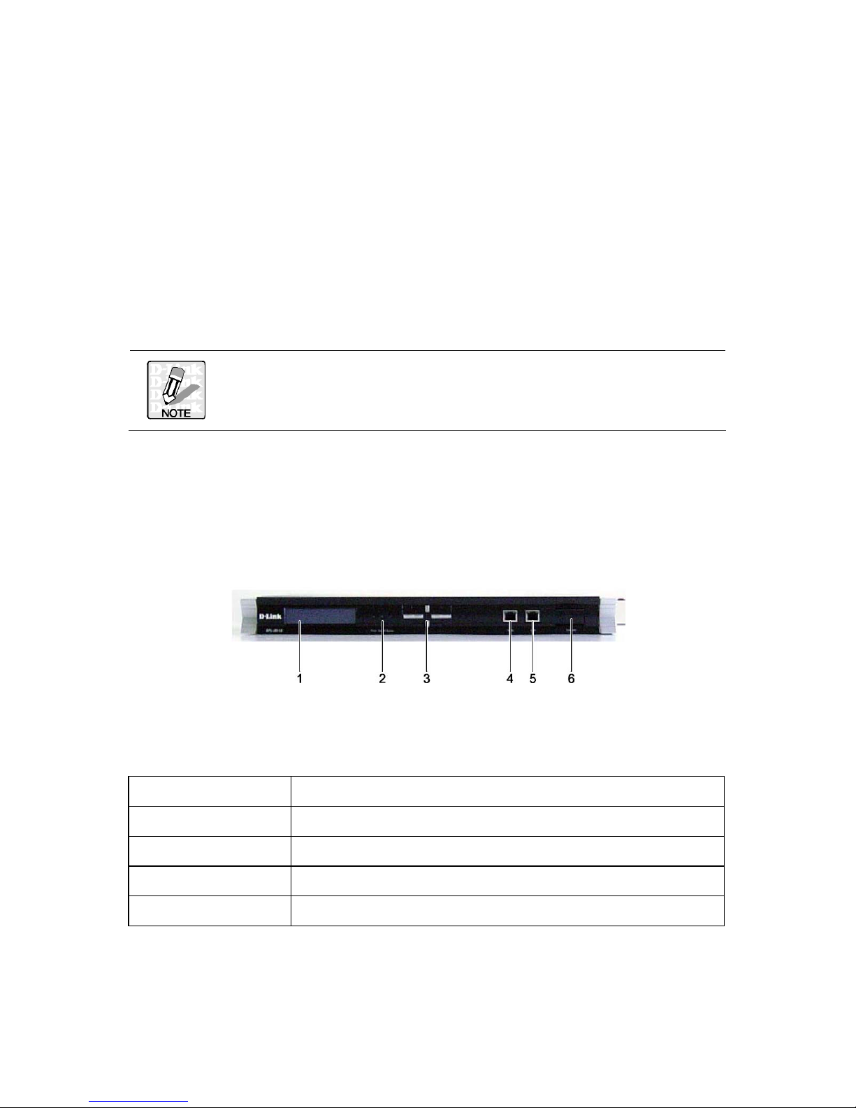
IDENTIFYING COMPONENTS
The following illustrations show the front and rear of the DFL-M510.
FRONT VIEW
LCM BUTTON DESCRIPTION
The LCM buttons are described below.
Button Name Description
Up Scroll Up
Down Scroll Down
ESC Go back to the previous screen
Enter Next screen

2
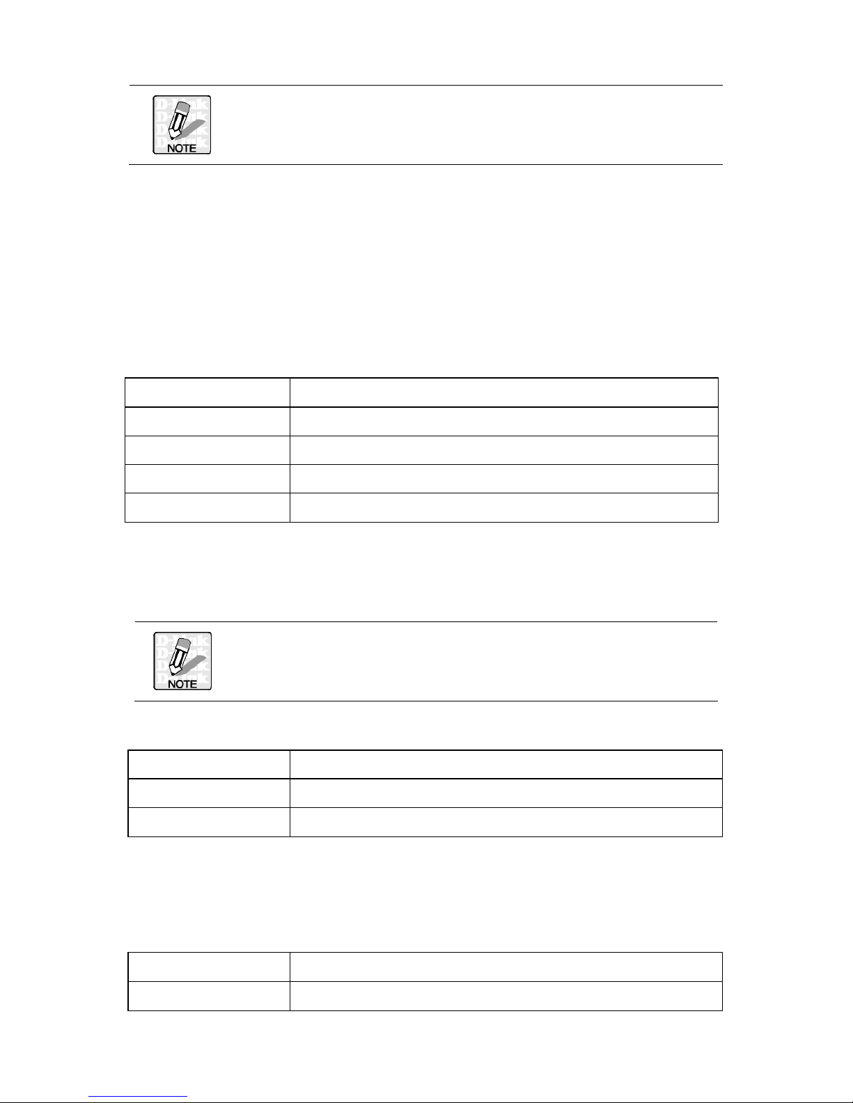
STATUS LEDS
The following table describes the status LEDs on the front of the DFL-M510.
Function Naming Color Status LED Description
Off Power off
Power Power Green
On Power
Off Power off (System not ready)
System System
Green
On System ready and running ok
Off Hardware bypass is not enabled
Bypass Bypass
Red
On Hardware bypass is enabled
Off Ethernet link OK and the speed is 10Mbps
Inbound
(Left)
Green
On Ethernet link OK and the speed is 100Mbps
Off No packets sending/receiving
On Link
Inbound
(Right)
Inbound
(LAN)
Green
Blinking Activity, port is sending/receiving data
Off Ethernet link ok, and the speed is 10Mbps
Outbound
(Left)
Green
On Ethernet link ok, and the speed is 100Mbps
Off No packets sending/receiving
On Link
Outbound
(Right)
Outbound
(WAN)
Green
Blinking Activity, port is sending/receiving data
REAR VIEW
1
Power socket
2
Power switch
3
Detailed information on the LCM can be found in the Appendix.
See “Appendix A: The Command Line Interface” on page 107.
CONFIGURING THE DFL-M510
Before managing the DFL-M510, it must be initialized. This procedure is accomplished
through the DFL-M510 Command Line Interface. Access to the Command Line
Interface can be made either through SSH or from a terminal connected directly to the
DFL-M510.
You can use Hyper Terminal, SSH v2 or br owser to set up the IP parameters of the
DFL-M510. The following are the default settings:
IP Address 192.168.1.1
Subnet Mask 255.255. 255.0
Default Gateway 192.168.1.254
User name admin
Password admin
CONFIGURATION THROUGH THE COMMAND LINE INTERFACE
Configure the DFL-M510 using the following parameters.
The IP address shown below is only an example. Instead use the IP
address for your network.
IP Address 192.168.62.100
Subnet Mask 255.255.255.0
Default Gateway 192.168.62.1
1. Connect one end of the RS-232 cable to the console port on the DFL-M510 and the
other end to the COM1 or COM2 port on the PC. (The pin-out definitions are shown
below.)
Terminal Emulation VT-100, ANSI, or auto
Bit per Second 115200
4
Data B its 8
Parity None
Sto p B i t s 1
Flow Control Nine
2. To open a connection in Windows 95/98/NT/2000/XP go to, Program Files
Accessory → Communications → Super Terminal.
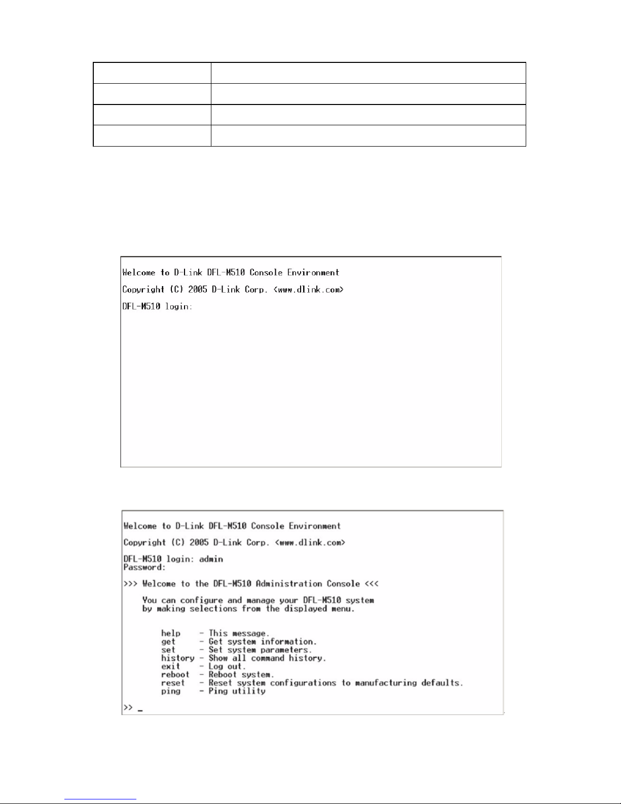
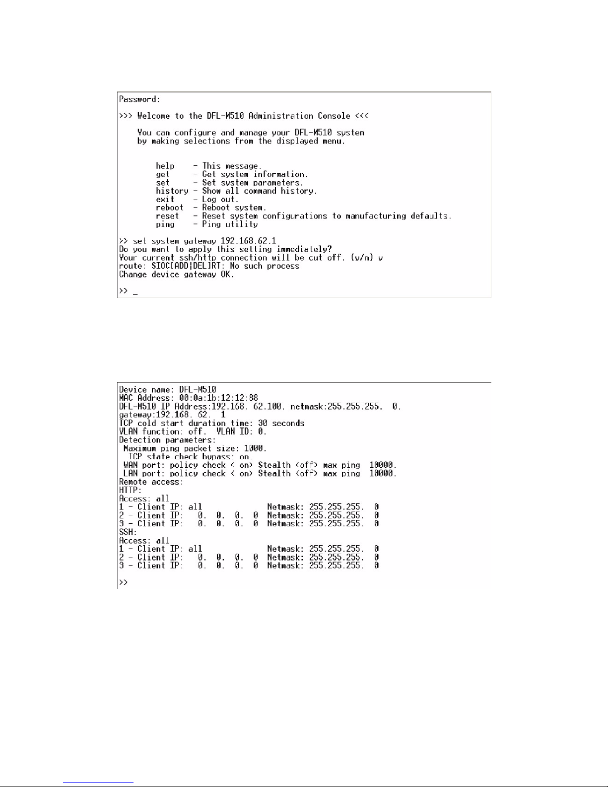
3. Once you access the Command Line Interface (CLI) with a terminal connection,
press any key. The following prompt appears:
4. Type in the username and password.
5
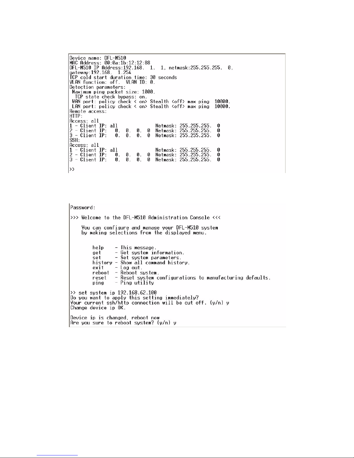
5. Use the get system command to get information on the DFL-M510.
6. Use the set system ip command to set the IP address.
6
7. After the system reboots, use set system gateway to set the default gateway.
8. After setting the IP address, Mask and Gateway, use the get system command to
get correct information. Use the web-based interface to configure other parameters.
See “Configuration Through a Web-based Interface” on page 7.
7
CONFIGURATION THROUGH A WEB-BASED INTERFACE
The DFL-M510 GUI is a Web-based application that allows you to manage the
DFL-M510. The GUI is a Java
™
applet application. Before accessing the GUI from any
PC, you must install Java Run Time Environment (J2RE V1.4.2 or above). Then you
can log on to the DFL-M510 from any computer on the network via a Web browser. You
can download J2RE from www.java.com or you can download it from the link within the
DFL-M510 GUI.
The PC you log in from must have the following system requirements:
z Microsoft W indows XP professional operation systems
z Device with Internet connection
z CPU: Intel Pentium4 2.0G or 100% compatible
z Memory: 512MB RAM or above
z Java Run Time Environment (J2RE V1.4.2 or above)
Refer to the following to log on to the DFL-M510.
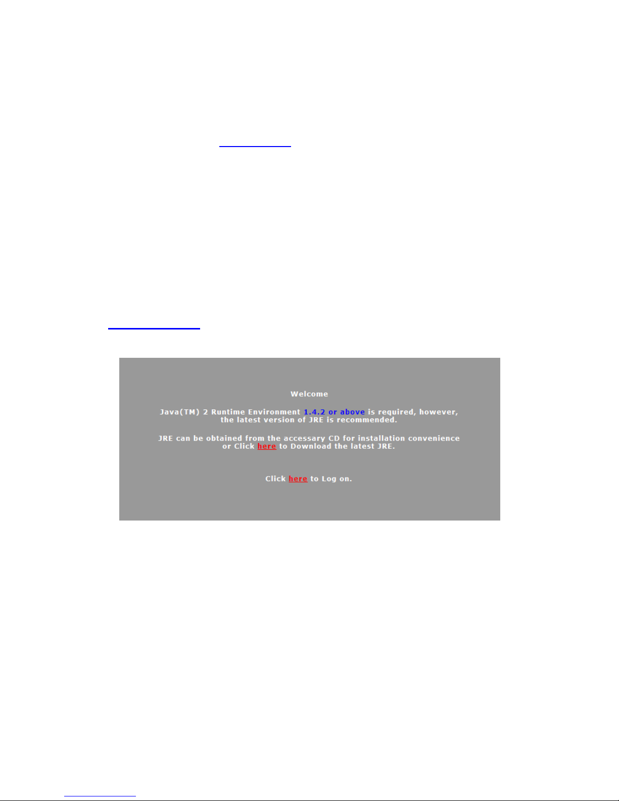
1. Open your Web browser and type the IP address into the Address Bar:
http://192.168.1.1. The login screen appears.
2. Click on the link to download the Java Runtime Environment.
8
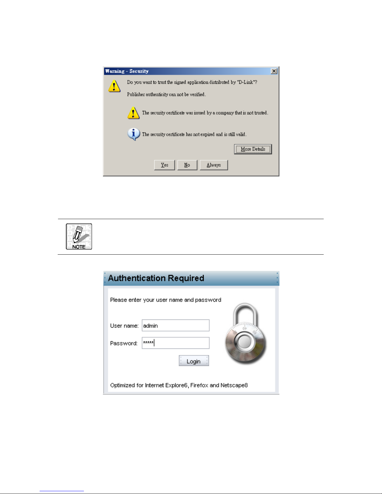
3. Click Run to start the installation. Follow the onscreen prompts to complete the
installation. The following Security Warning appears.
4. Click Always to continue and prevent this screen appearing again. The login screen
appears.
The IP address shown below is only an example. Instead use the I P
address for your network.
5. Type in the default account name admin and the default password admin and
click Login.
9
For security reasons, you should change the default password to a
more secure password after you have completed the setup. See
Chapter 4 “User Authentication” on page 60.
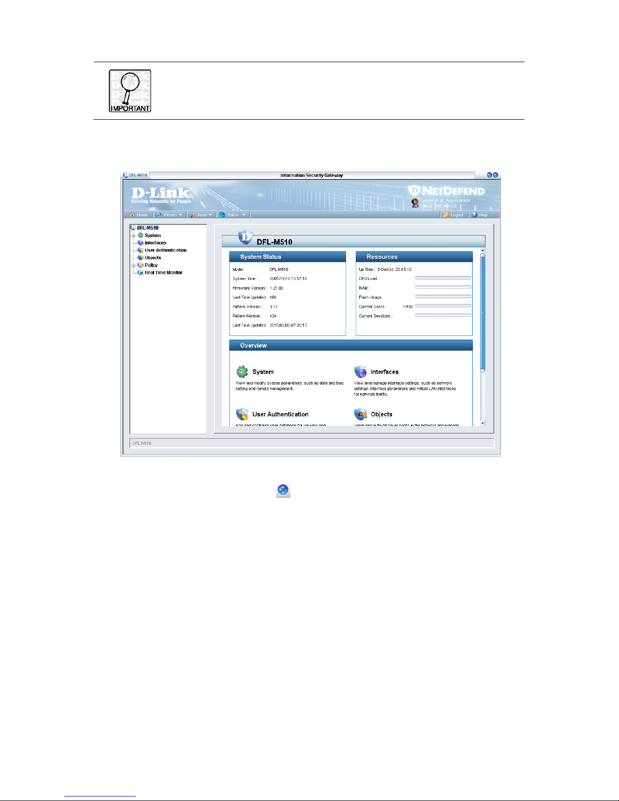
6. After two or three minutes, the GUI opens on the DFL-M510 main screen.
7. To log out click the Close button at the top-right of the screen.
RUNNING THE SETUP WIZARD
The Setup Wizard helps you to quickly apply basic settings for the DFL-M510. You will
need the following information for your network to complete the Setup Wizard:
z IP Address
z Subnet Mask
z Default Gateway
z DNS Server
Regarding how to configure DFL-M510 via Setup Wizard, see the “Wizard” section on
page 10 for more detail.
10
The first time you log on to the DFL-M510, the Setup Wizard starts
automatically.
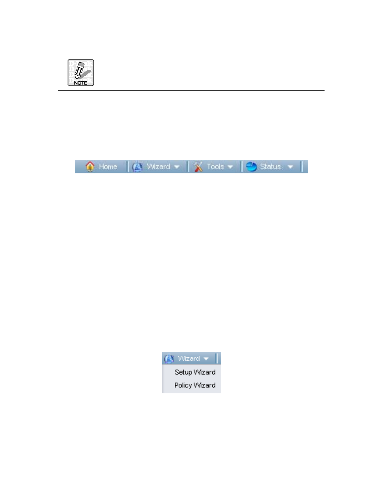
TOOLBAR
The Toolbar provides many handy and frequent-use functions for you. These functions
are mainly divided into three categories: Wizard, Tools and Status, illustrated as
below.
The Wizard, including Setup Wizard and Policy Wizard, guides you step-by-step to
complete the entire procedure, helps you easily configure the essential system
information and policy configuration for DFL-M510.
For system maintenance, several handy tools such as Backup, Reset, Upgrade, and
Debug, are provided in the Tools, enable you to quickly maintain the system
configuration.
The Status is the most fabulous function you may frequently utilize, for instance,
System information, Logging information and Report for network status. The current
status of the supported application DFL-M510 can monitor and manage is provided in
the Policy Status. Also, you can obtain the information of pattern version in the
Pattern Status.
WIZARD
The Wizard provides a handy ways for you to quickly apply system and policy settings
for the DFL-M510. On DFL-M510, two wizards shown as below are provided - Setup
Wizard and Policy Wizard.
11
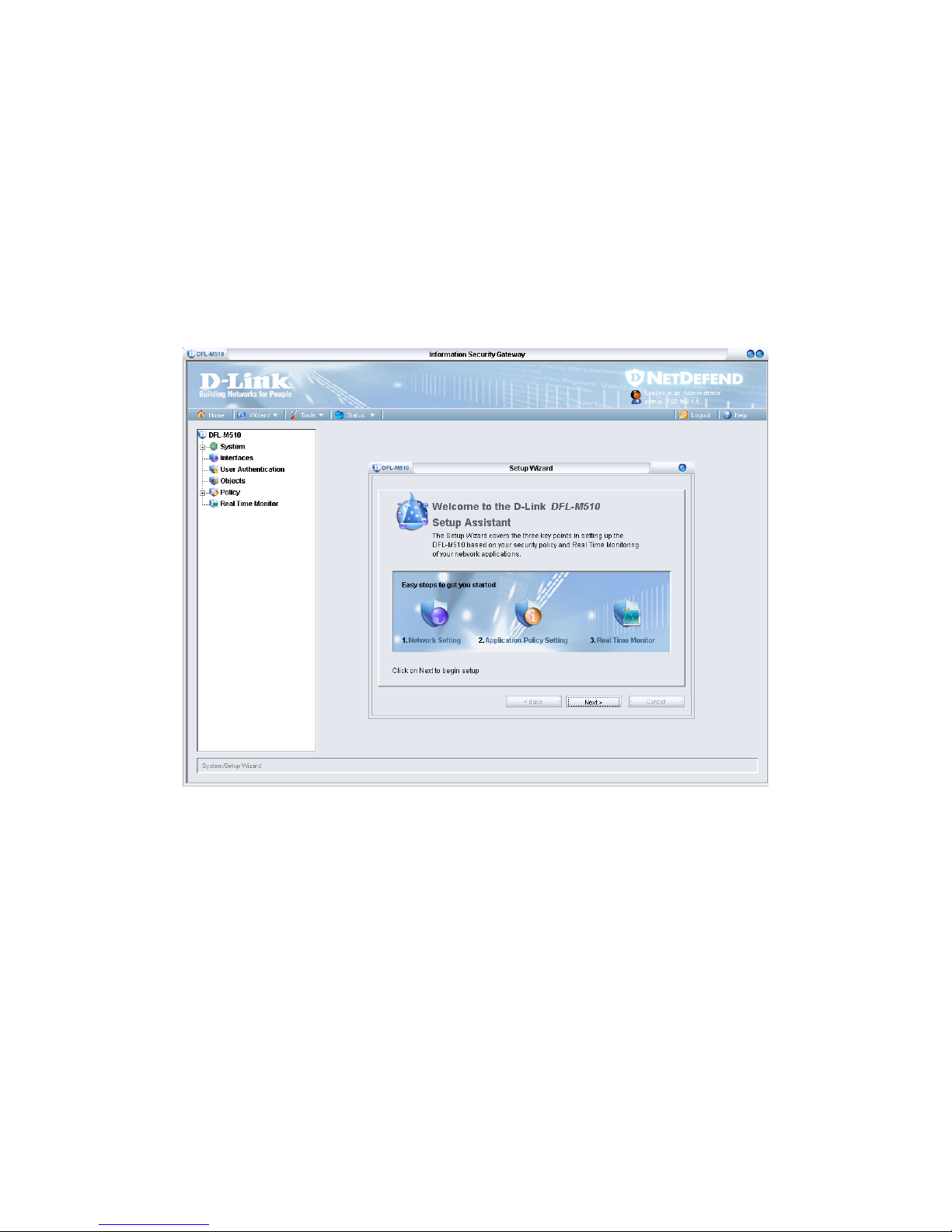
SETUP WIZARD
When initializing the DFL-M510 first time, the Setup Wizard will launch automatically
after you logon the device. The Setup Wizard will guide you step-by-step through the
entire procedure. After the procedure is completed, the basic system inf ormation for
DFL-M510 is configured.
To run the Setup Wizard:
1. Go to Toolbar, click Wizard, Setup Wizard. The Setup Wizard window appears.
Click Next to continue.
12
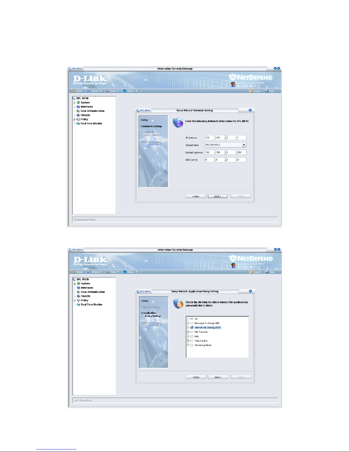
2. You need to provide your IP Address, Subnet Mask, Default Gateway, and DNS
Server address to enable the device to connect to your network. If the net work was
set by CL I, ch eck the settings here. Type in the required information and click Next.
3. Select the check boxes for the applications you want to block and click Next.
13
You can leave all the boxes unchecked to be sure the DFL-M510 is set
up correctly. Later you can add applications to be blocked in the
Policy menu. See Chapter 6 “Policy” on page 72.
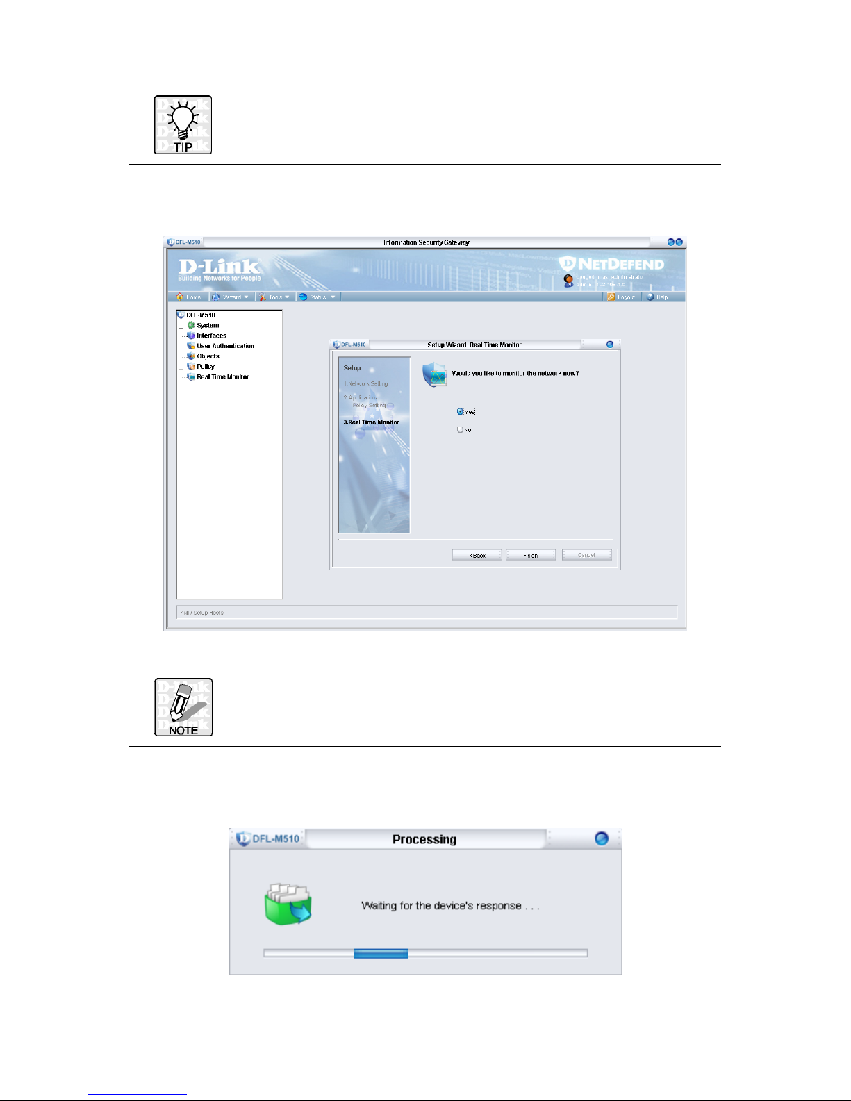
4. Select the No radio button and click Finish.
If you select Yes in the screen above, you are taken to the Real Time
Monitor screen when setup completes. See Chapter 7 “Real Time
Monitor” on page 94.
It takes 30 seconds for the settings to be processed and then the following screen
appears:
14
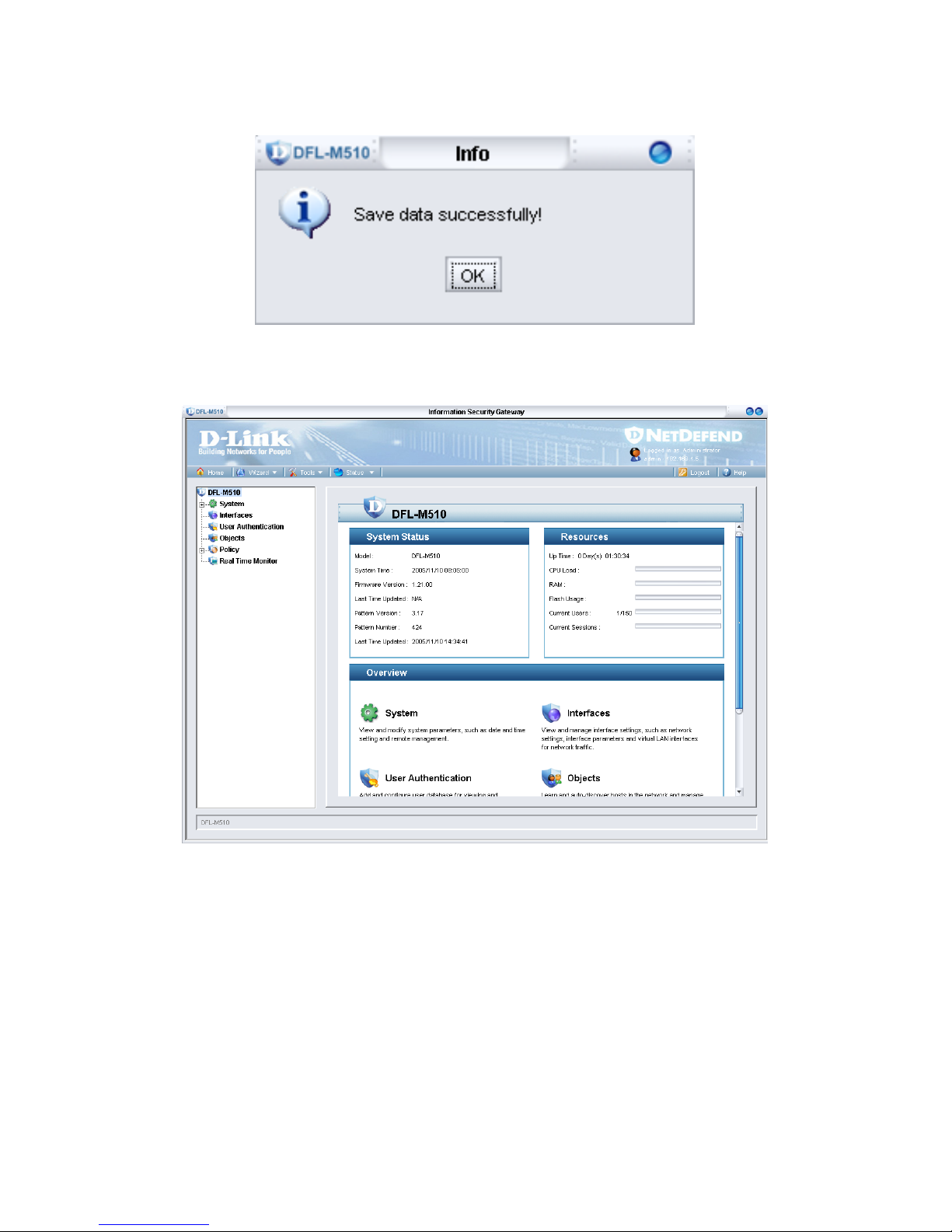
When the setup is successful, the following screen appears:
5. Click OK. The System status screen is shown for your information.
15
POLICY WIZARD
The Policy Wizard helps you to simplify the policy configurations and apply policy
settings for the DFL-M510. Follow the steps as below to experience the easy use and
convenience of Policy Wizard:
TO CREATE A NEW POLICY TEMPLATE VIA POLICY WIZARD
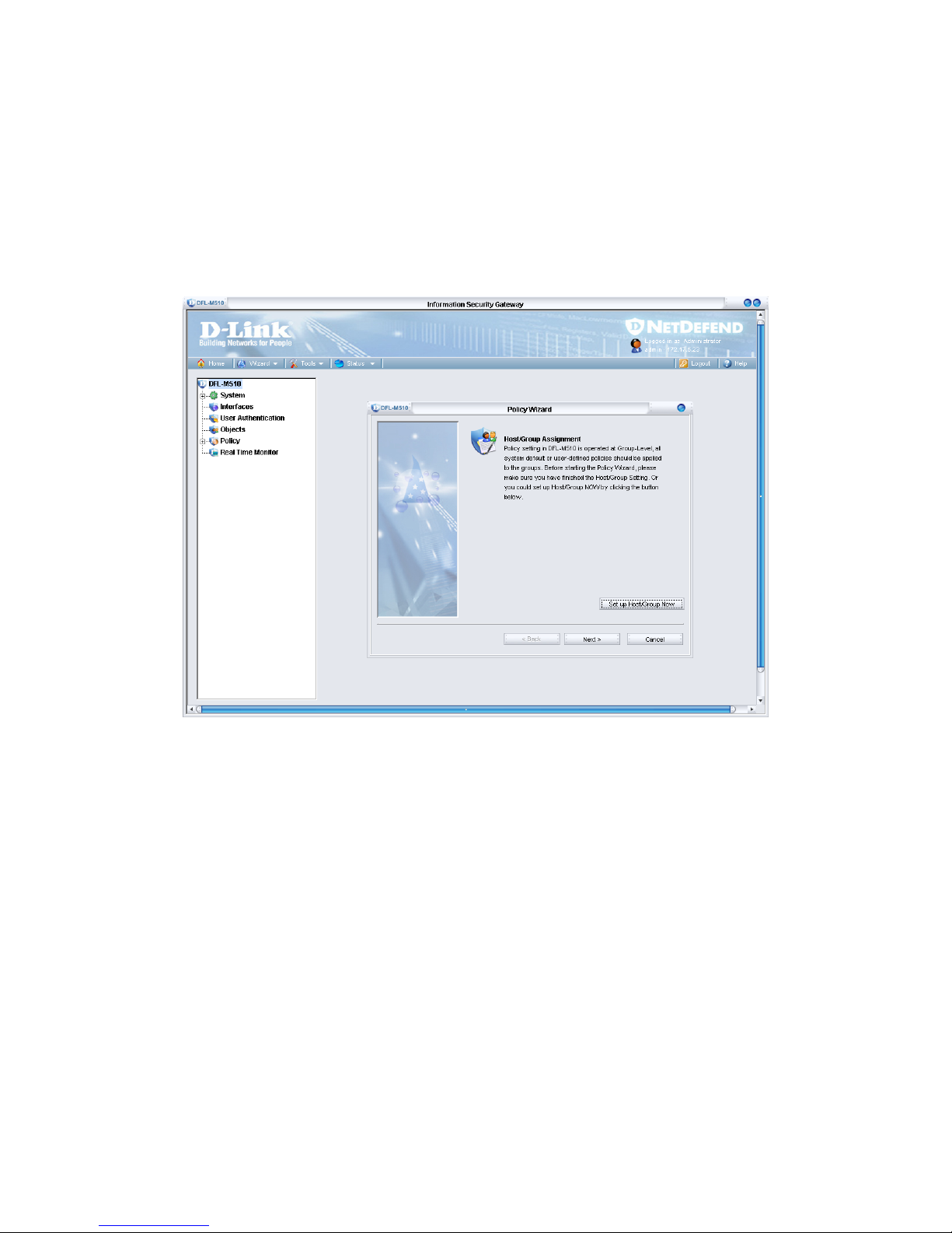
1. Go to Toolbar, click Wizard, Policy Wizard. The Policy Wizard window appears.
16
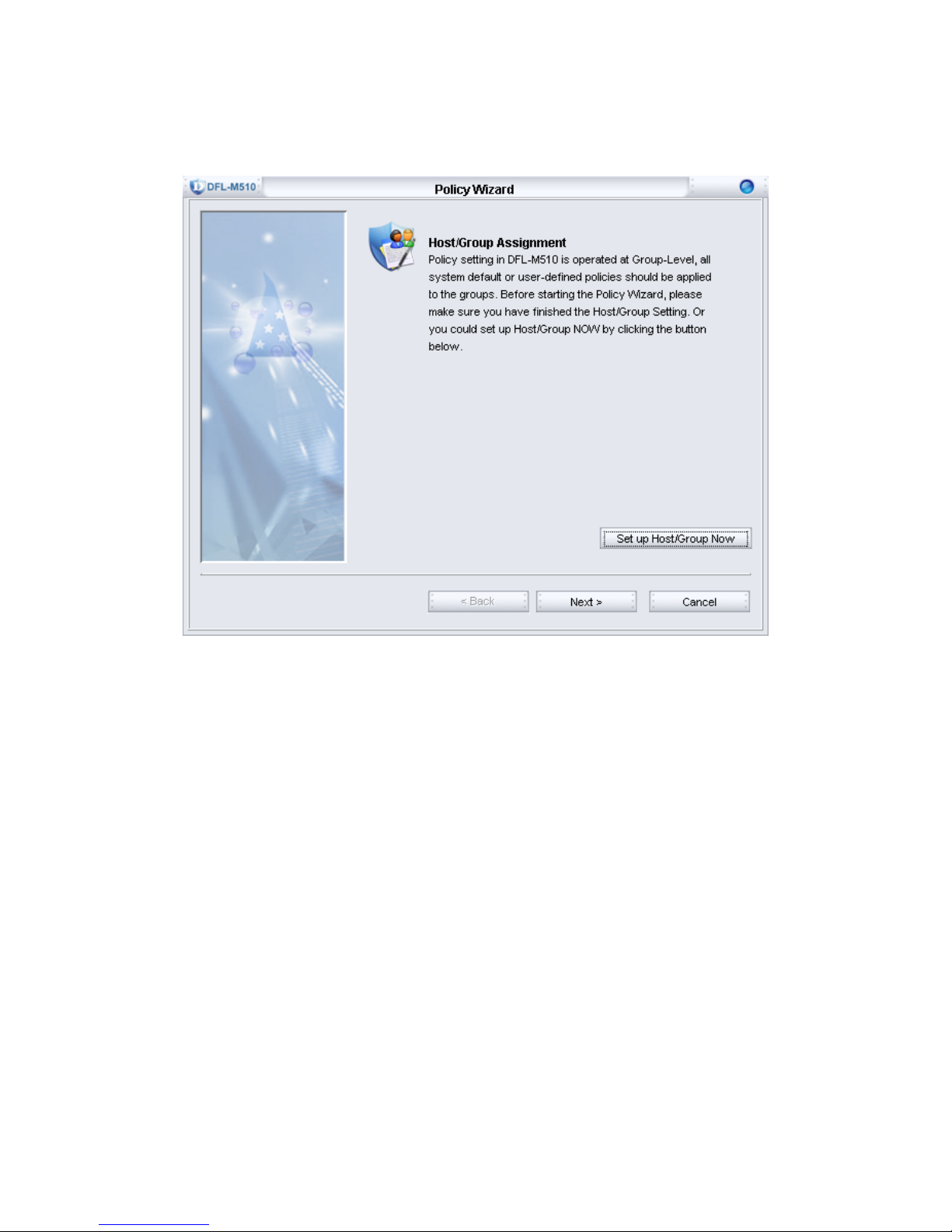
2. You can choose to manually setup Host/Group information here or latter in the tree
view list. To setup the Host/Group information, click the “Set up Host/Group Now”
button, otherwise, click Next to continue.
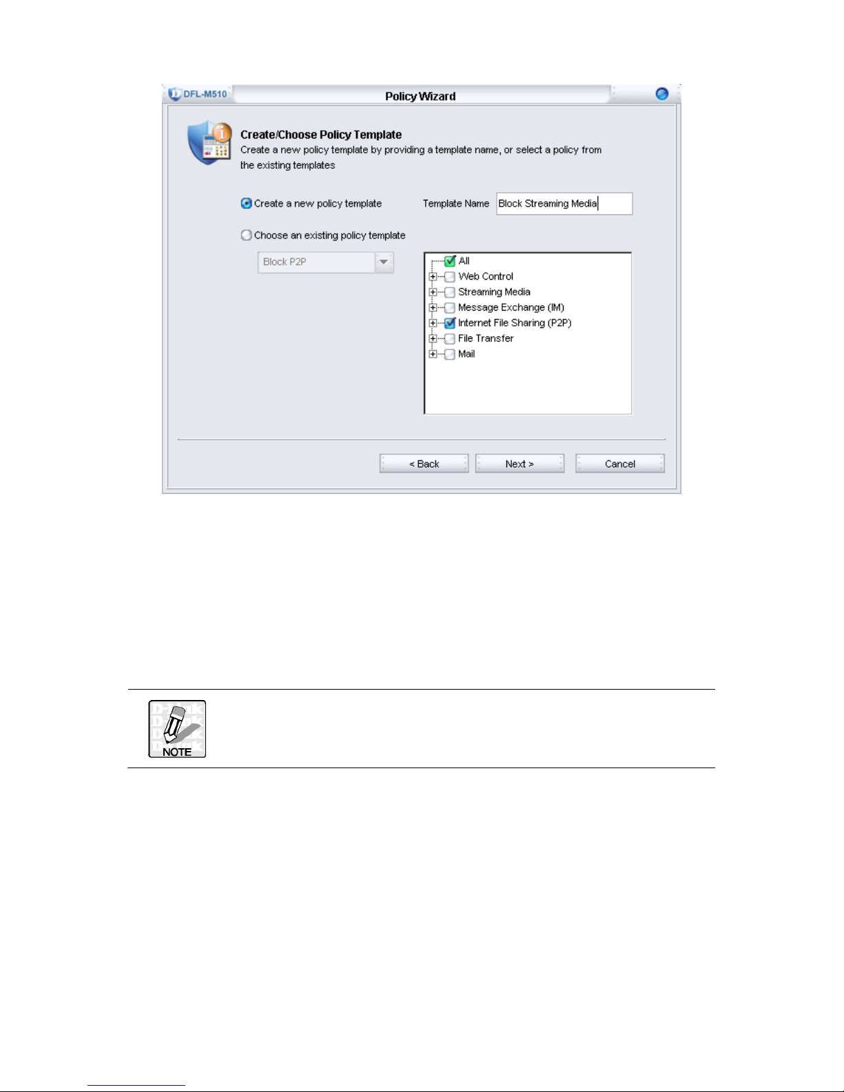
3. In this step, you can choose either to create a new policy or to select an existing
policy template.
17
To create a new policy, you need to provide a policy name in the “Template Name”
field, and click Next to continue. Here Block Streaming Media is the example.
To utilize an existing policy template, click the radio button “Choose an existing
policy template”, and select an existing policy template from the pull down list. The
detail setting for the policy template you choose will appear in the three view list for
your information, and click Next to continue.
If you select “Choose an existing policy template”, and click Next,
you are taken to the Step 5 for further configuration.
18
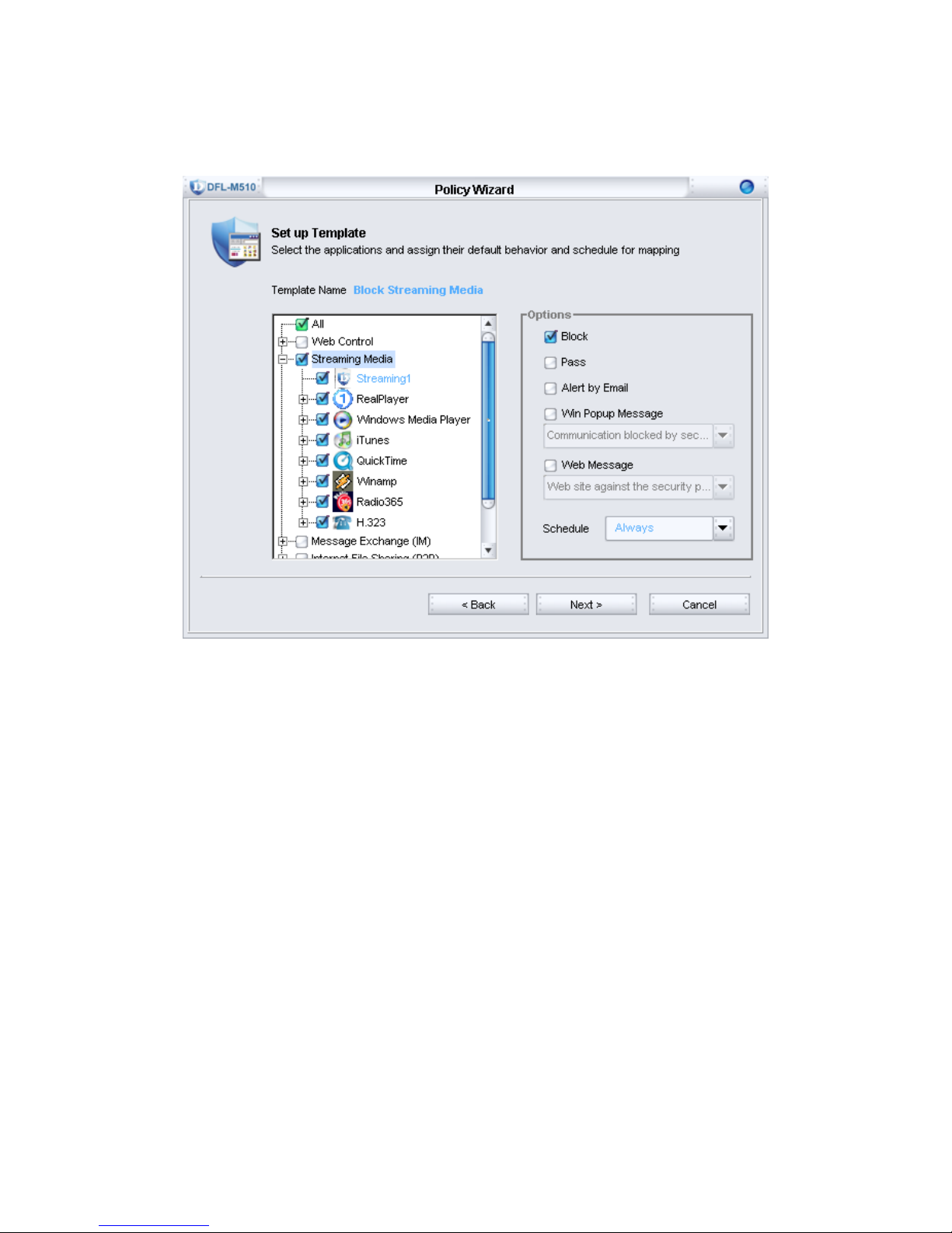
4. Specify the corresponding action and schedule for the “Block Streaming Media”
template. Here the “Block” checkbox is checked, and the schedule is “Always”.
Click Next to continue.
19
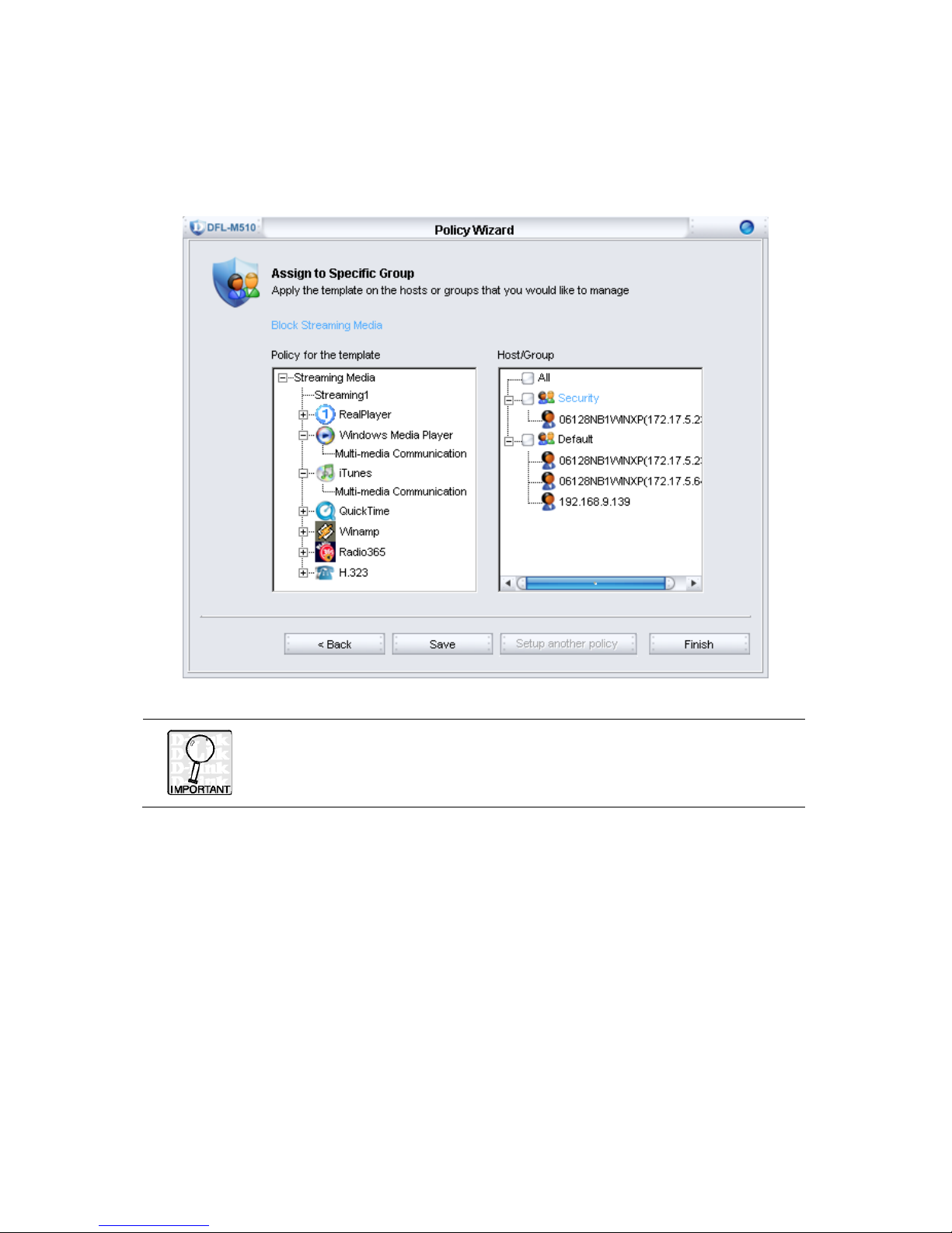
5. Assign the “Block Streaming Media” template to a specific group. In this step, it is
optional to assign the policy to a specific group. You can latter configure it in the
“Policy Setting” Tab when you require. In this example, the policy does not apply to
any specific group immediately. Click Save to save your setting for the new policy
template.
Do not forget to click the “Save” button in this step; otherwise you will
lose your entire configuration for your new policy template.
20
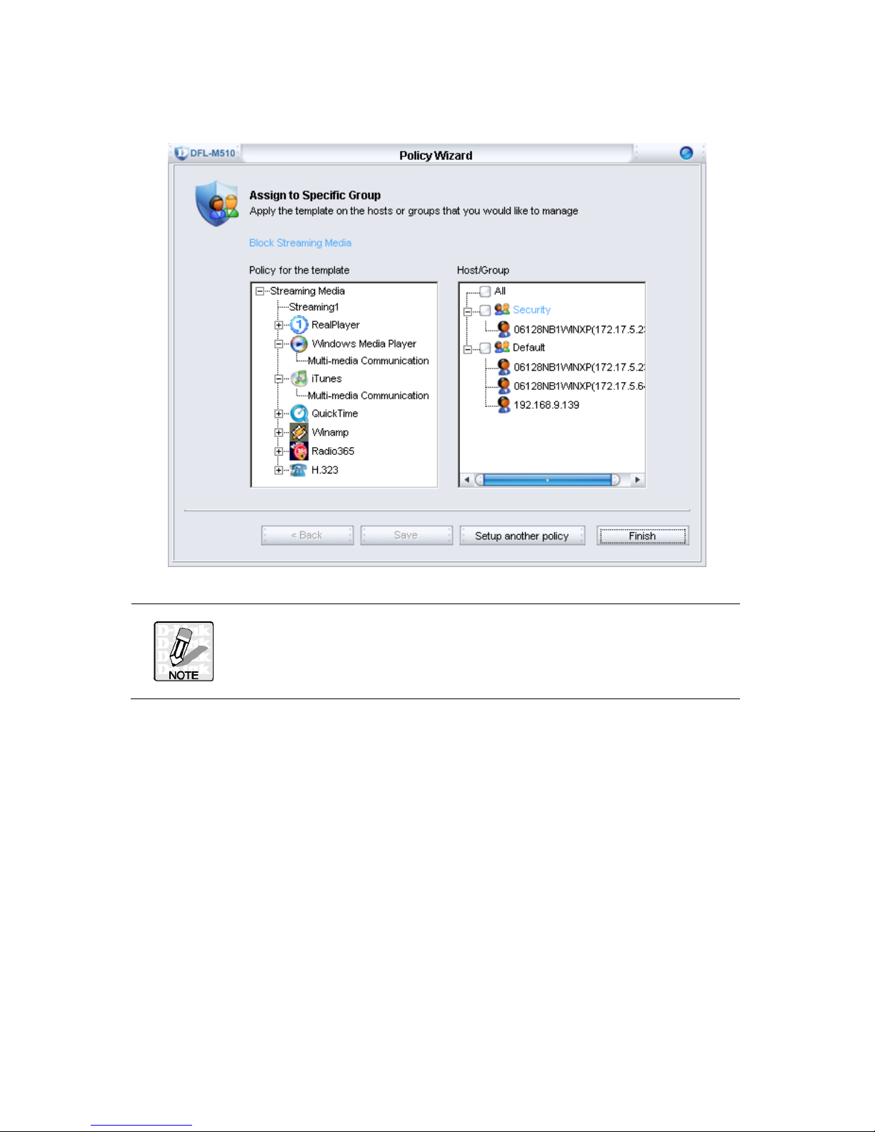
6. After saving your new policy template, you can choose either to finish the Policy
Wizard or to set up another policy template via the wizard.
The Policy Wizard provides a simple and easy way to set up your
policy setting, these configurations still can be modified latter in the
configuration tabs of “Policy Setting”. See Chapter 6 “Policy” on page
72 for more information.
21
TOOLS
The Tools includes the handy tools for the system maintenance, including Backup,
Reset, Upgrade and Debug. Each of them will be described as below.
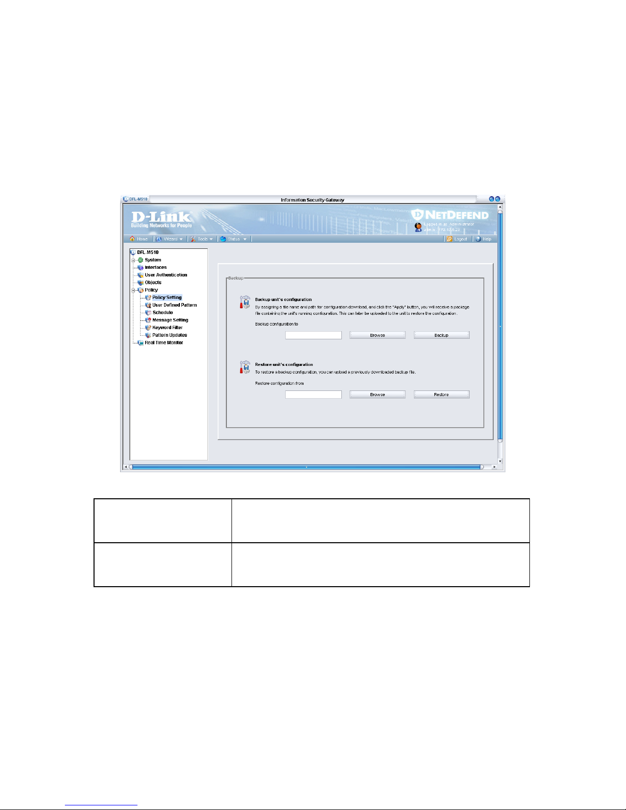
BACKUP
Go to the Toolbar, click Tools, Backup. The Backup window appears.
Backup configuration to
Press Backup configuration to store the currents settings to a
file. The backup configuration dialog displays to ask the name
of the stored file.
Restore configuration from
Press Restore configuration from to restore setting from a file
on the management GUI. The restore configuration dialog
would display to ask the name of the file.
 Loading...