

Page 1
Contents of Package:
DG-102S VoIP Station Gateway
Power adapter
CD-ROM, including User’s Manual
Quick Install Guide
Requirements:
RS-232 Console Cable
Two RJ-45 CAT-5 Straight-Through Cables
For more information regarding cabling, please see the appendix at the back of this
guide or refer to the User’s Manual on the CD-ROM.
Connecting the DG-102S VoIP Gateway
to your network
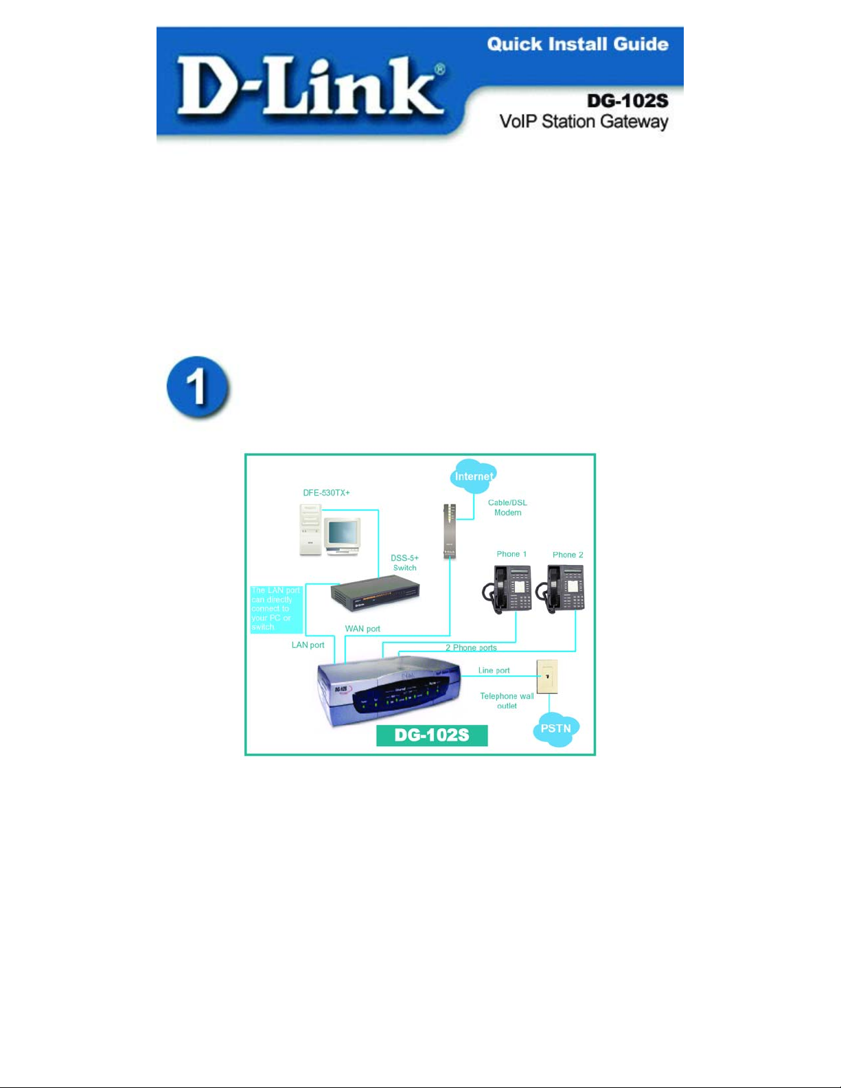
When you have completed the steps in this installation guide, your
connected network may look similar to this:
Page 2
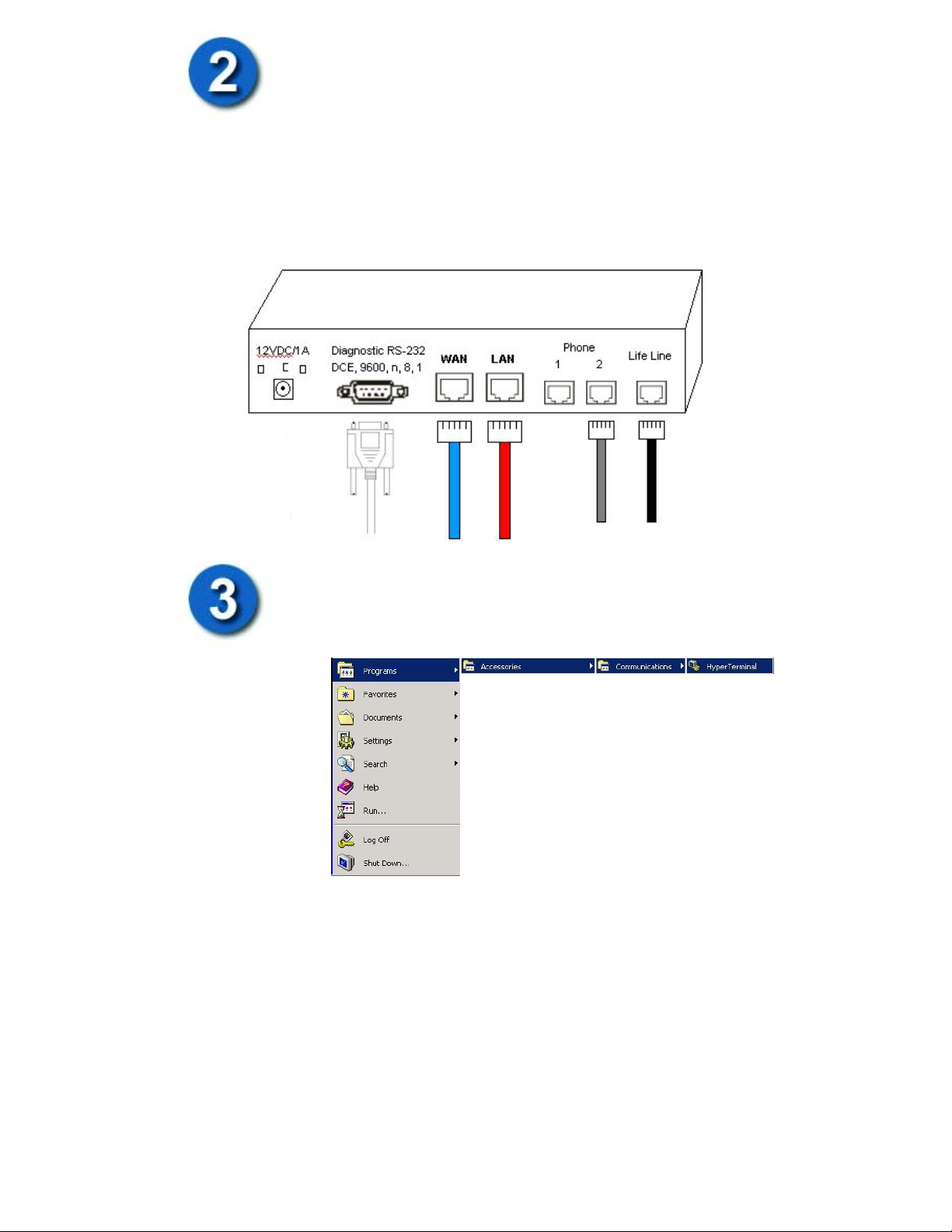
Starting with the WAN port, connect the Cable or DSL modem to the
DG-102S WAN port using an Ethernet cable. Next, connect the PC or
switch to the LAN port with another Ethernet cable. Then, connect
your regular analog telephone(s) directly into either of the two Phone
ports using RJ-11 phone cable. (Connect the Line port to a standard
telephone wall outlet for PSTN Life Line Support)
Finally, plug one end of the RS-232 console cable to the DG-102S
Diagnostic RS-232 port and the other end to an available serial port
on your computer.
(Do Not plug in the power adapter yet!)
On the same computer where the RS-232 console cable is connected
to, open up a HyperTerminal screen by clicking on
Start->Programs->
Accessories->
Communications->
HyperTerminal
Page 3
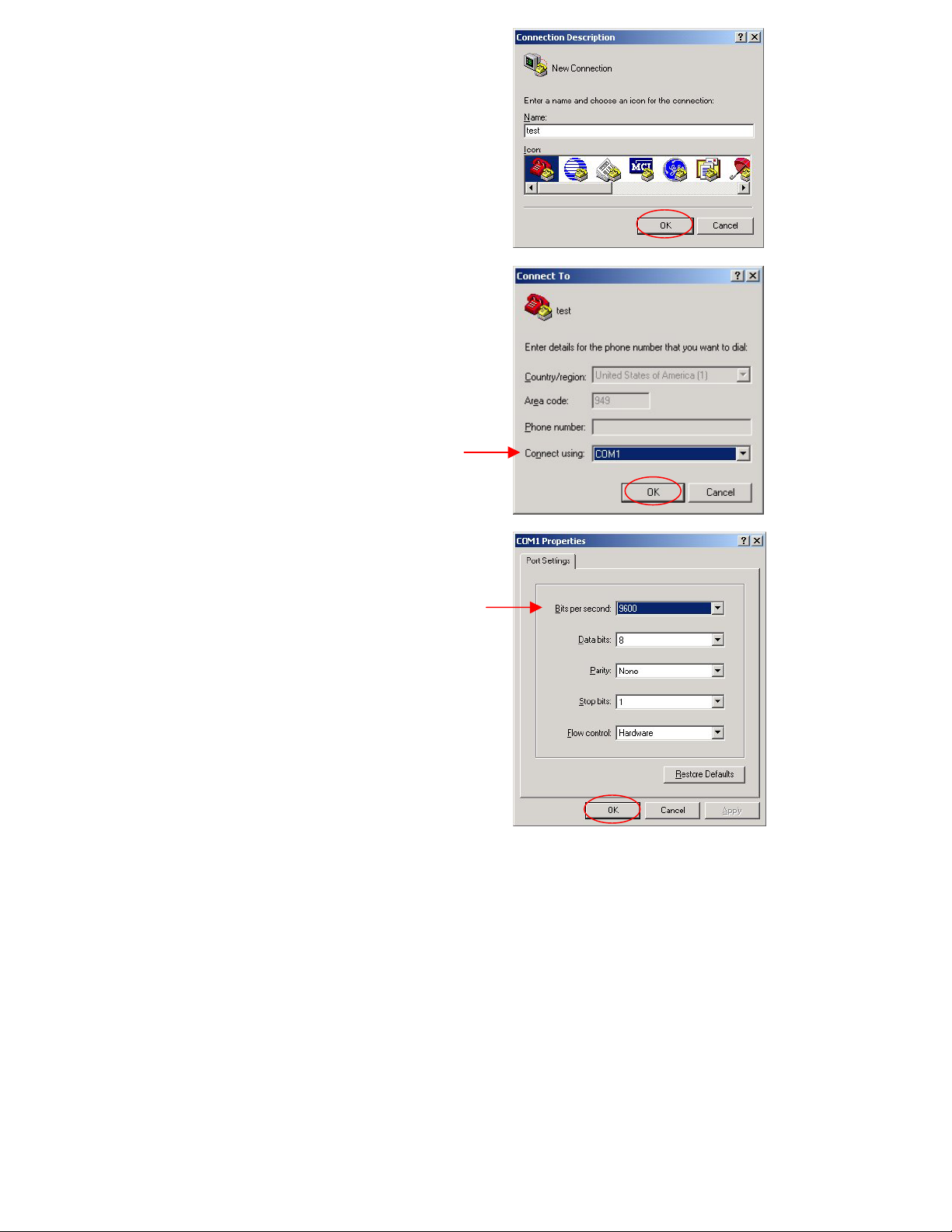
When the Connection Description screen
appears, it will prompt for a “Name” for the
New Connection. Enter any name you desire.
Click “OK”
The next screen will ask how to connect. In
the “Connect using” option, choose the COM
port that is in use by the serial port which the
RS-232 console cable is connected to.
Click “OK”
The COM port properties screen will then
appear. Select 9600 as the “Bits per second:”
Bits per second: 9600
Data bits: 8
Parity: None
Stop bits: 1
Flow Control: Hardware
Click “OK”
There should now be an empty white HyperTerminal screen on your computer screen.
Page 4
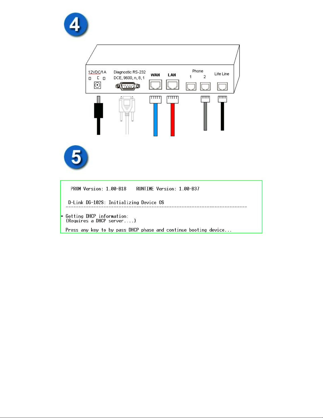
Plug in the power supply as shown.
The Power LED in the front panel will turn on to indicate proper
operation.
After plugging in the power supply, the HyperTerminal screen should
now display the following screen:
The HyperTerminal screen will prompt you to press any key. Press the Space Bar
button on your keyboard to allow the DG-102S to finish the boot process. You should
now see the DG-102S go through its POST (Power On Self Test).
At this point, you may close the HyperTerminal screen and move on to the next
section.
Page 5
Configuring the VoIP Gateway using a Web Browser
Setting Up a Connection
In order to use a web browser to configure the VoIP gateway, you
must be sure it has a valid Ethernet connection from the PC to the
LAN port. The VoIP gateway comes with a default LAN (Local Area
Network) IP address of 192.168.0.1 and a subnet mask of
255.255.255.0.
Make sure the PC is in the same IP range as the VoIP gateway. You can do this by
changing the IP address of the PC.
By default, the DG-102S is a DHCP Server. You can set your computer to obtain an
IP address. Follow the below steps to do so. If you prefer, you can set your computer
up with a static IP address in the range of 192.168.0.2 ~ 192.168.0.254.
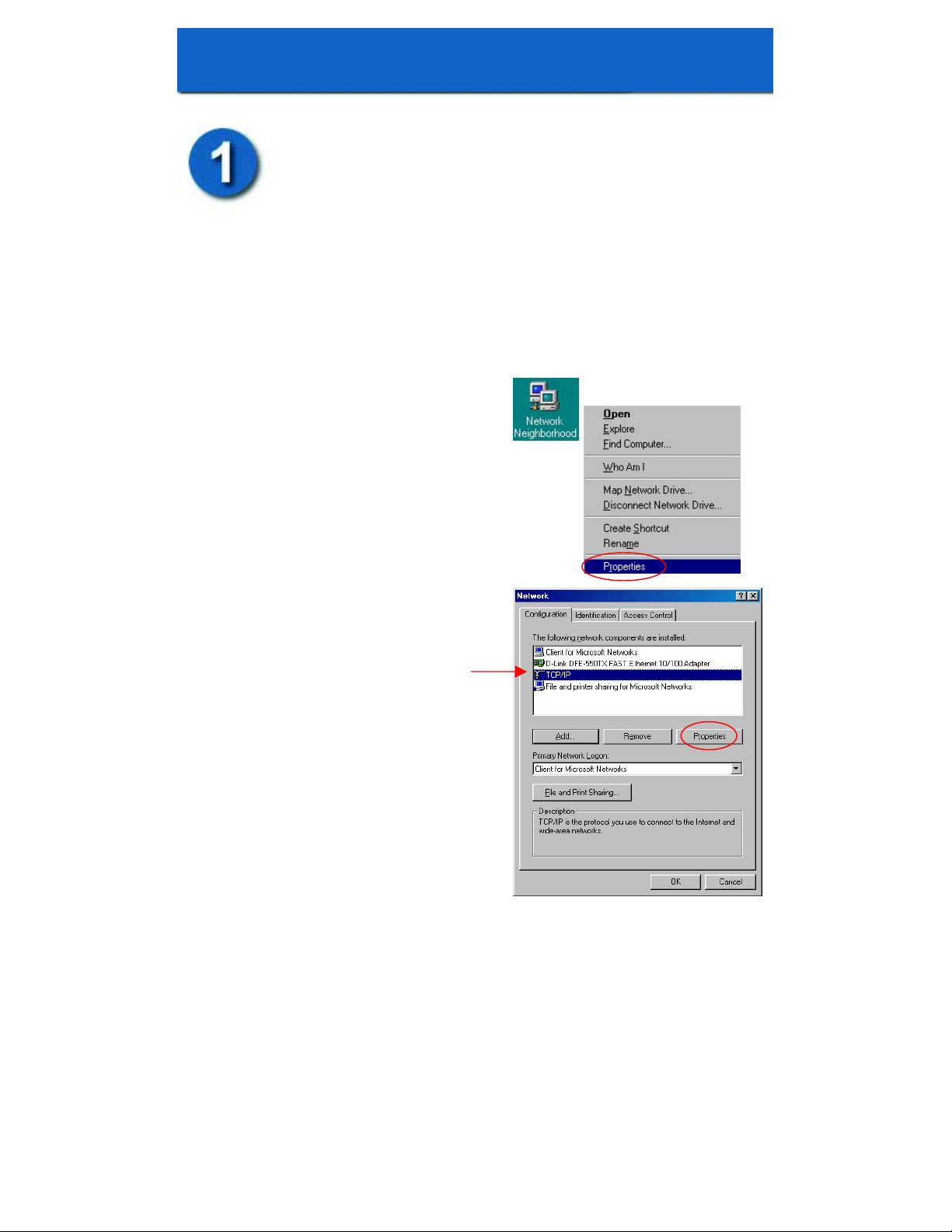
Right-Click the Network
Neighborhood (Win 98/98SE)
or My Network Places (Win ME/2K/XP)
icon on your desktop.
Select “Properties”
Highlight the TCP/IP setting for the installed
Ethernet Network Adapter.
Click “Properties”
Page 6
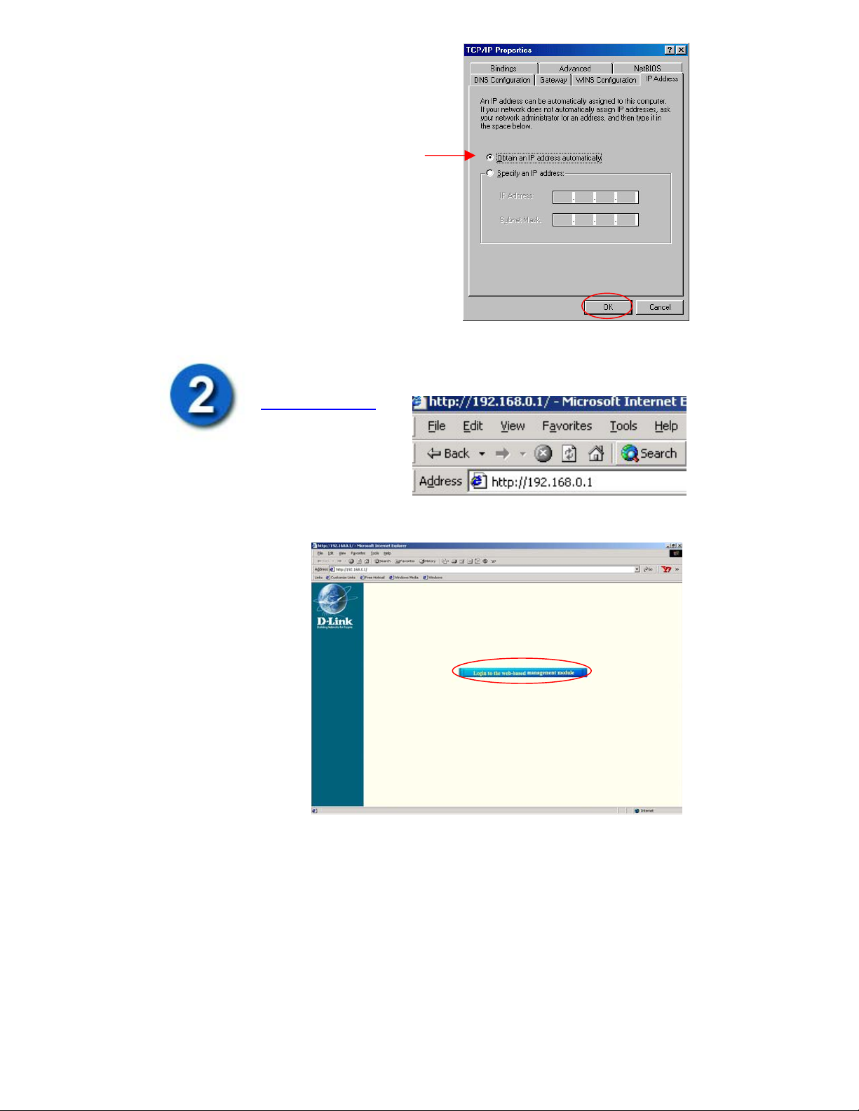
At this screen, select the
IP address tab. Select
Obtain an IP Address
Automatically.
Click “OK”
If you are prompted to restart your computer,
please do so. When the computer restarts, it
will automatically receive an IP address from
the DG-102S.
Please open the Web Browser and enter this URL:
http://192.168.0.1
Note: The DG-102S requires Internet Explorer 4.0 or higher, or Netscape
Communicator 4.0 or higher.
The following screen
should appear on the
browser.
Page 7
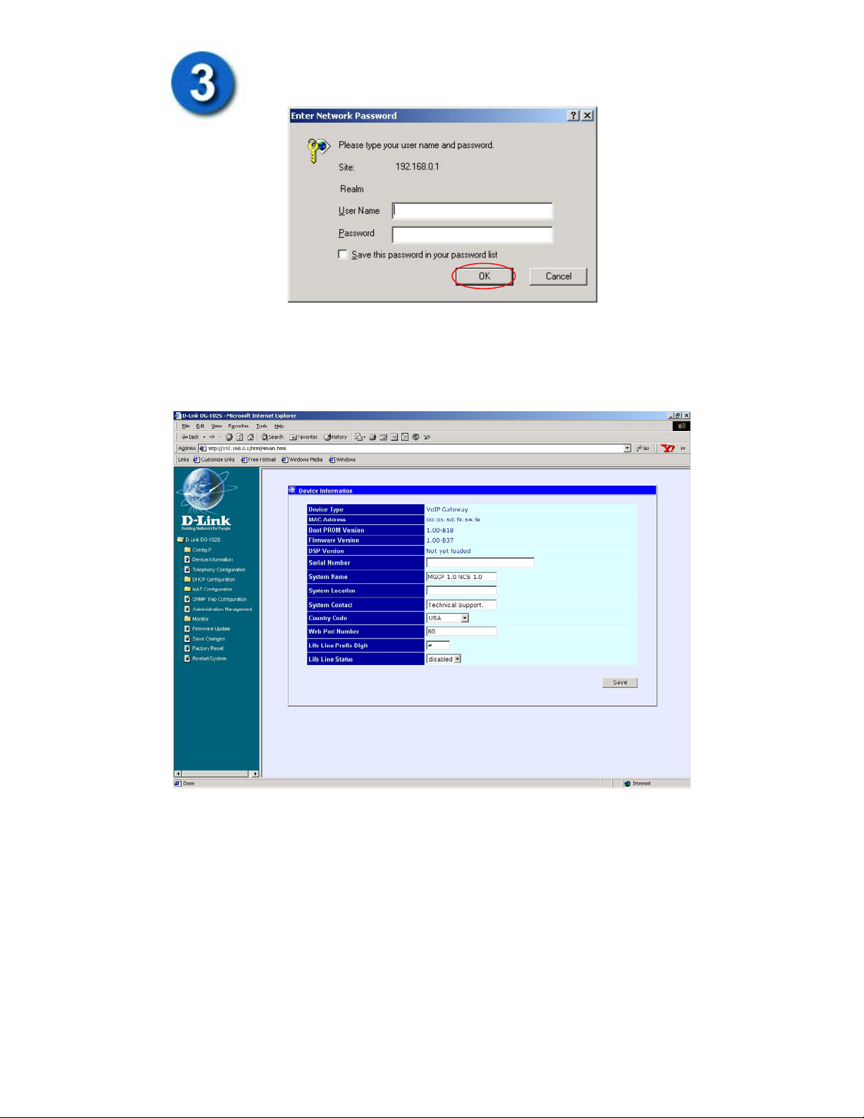
Click on the “Login to the web-based management module” button.
The following pop-up window will be displayed:
By Default, the VoIP gateway does not have a Username or
Password. To log in, simply click “OK”.
The following window will be displayed:
Page 8
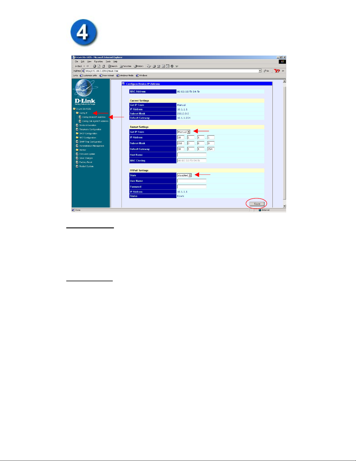
To begin configuring the device, click on the “Config IP” folder on
the left-hand side menu. Then click on “Config Device IP Address”
right below it. The following window will appear.
Restart Settings
• If you are assigned a static IP address by your ISP, choose “Manual” in the Get
IP From option. Feel in the appropriate IP information provided to you by your
ISP.
• If you are assigned to obtain an IP address, choose “DHCP” in the Get IP From
option. Fill in the Hostname if required by your ISP.
PPPoE Settings
• If you are assigned to use a PPPoE authentication, change the State option to
“Enabled”. Please fill in the PPPoE Username and Password provided to you by
your ISP.
Once you have filled in the appropriate information for your Internet connection, click
on the “Save” button at the bottom-right.
Page 9
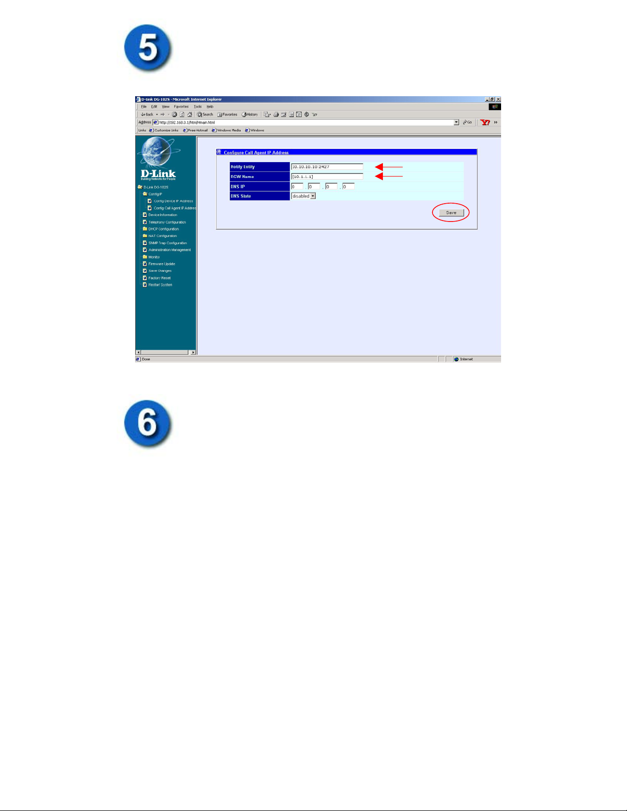
Click on “Configure Call Agent IP Address”. Enter in the Notify
Entity and RGW Name provided to you by your ISP.
Administration Management
For security purposes, it is recommended that you create an
administrator account for the DG-102S. This account will be used to
login to the DG-102S web-interface for configuration.
To add or change a User Account, fill in the appropriate information in the “User
Name,” “Old Password” (if applicable), “New Password,” and “Confirm New
Password” fields.
Page 10
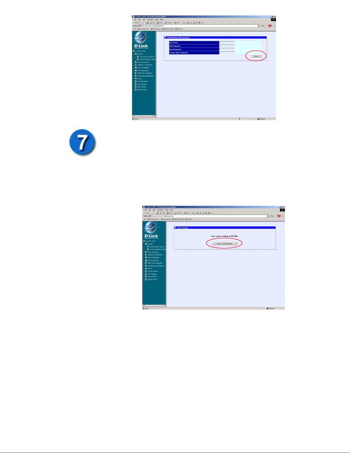
Click “Save”
Save Changes
After the settings have been saved to NV-RAM, they will become the
default settings for the device, and they will be used every time it is
powered on, reset or rebooted. The only exception to this is a factory
reset, which will clear all settings and restore them to their initial
values, which were present when the device was purchased.
Click on “Save Changes” on the left-hand side menu. This window will appear
prompting to save the configuration.
Click on the “Save
Configuration” button to
save the system settings to
NV-RAM.
The DG-102S will save the
changes and automatically
restart.
Page 11
Appendix
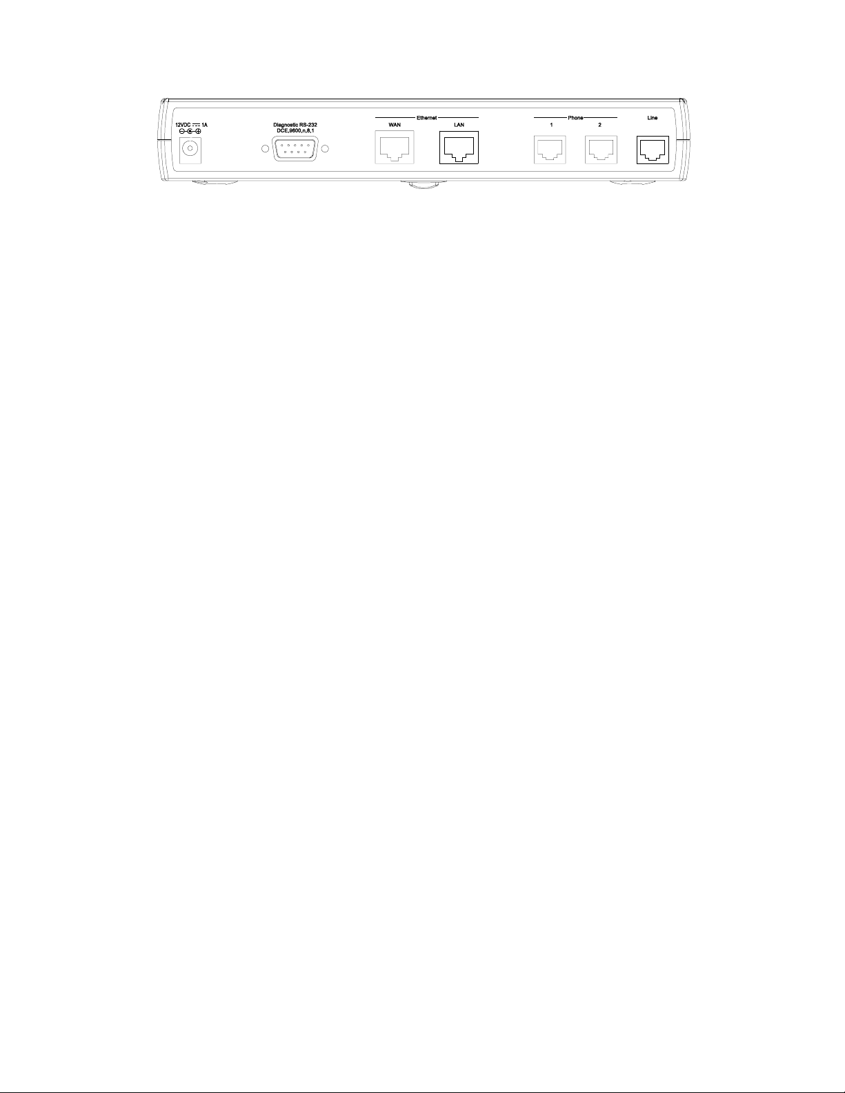
1. To connect your gateway (WAN port) directly to cable or DSL modem use
“Straight-through cable.”
2. To connect your gateway (LAN port) directly to your computer or switch
(Uplink port) use “Straight-through cable.”
3. A “Serial cable” is used to connect your PC to the gateway for “Command
line Configuration.” (Please refer to the User’s Manual for more details.)
4. To connect your normal telephones directly to your gateway (Phone ports)
using “RJ-11 phone cable”. (The third port on the right labeled “Line” is for
PSTN Life Line function. It’s for connecting to a standard telephone wall
outlet through an approved No. 26 AWG or larger telecommunications line
cord.)
Page 12

Building Networks for People
 Loading...