

Page 1

D-Link DFL-1100
Network Security Firewall
Manual
October 7, 2004
Building Networks for People
Page 2

Contents
Introduction....................................................................................6
Features and Benefits..........................................................................6
Introduction to Firewalls .......................................................................6
Introduction to Local Area Networking..................................................7
LEDs & Hardware Connections............................................................8
Package Contents................................................................................9
System Requirements..........................................................................9
Managing D-Link NETDEFEND DFL-1100......................................10
Administration Settings...............................................................11
Administrative Access........................................................................ 11
Add ping access to an interface..................................................................12
Add Admin access to an interface ..............................................................12
Add Read-only access to an interface........................................................13
Enable SNMP access to an interface.........................................................13
System..........................................................................................14
Interfaces...........................................................................................14
WAN Interface Settings – Using Static IP...................................................15
WAN Interface Settings – Using DHCP......................................................15
WAN Interface Settings – Using PPPoE.....................................................16
WAN Interface Settings – Using PPTP.......................................................17
WAN Interface Settings – Using BigPond...................................................18
Traffic Shaping............................................................................................18
MTU Configuration......................................................................................19
VLAN .................................................................................................20
Add a new VLAN.........................................................................................20
Remove a VLAN.........................................................................................20
Routing ..............................................................................................21
Add a new Static Route...............................................................................22
Remove a Static Route...............................................................................22
High Availability..................................................................................23
What High Availability will do for you ..........................................................23
What High Availability will NOT do for you..................................................23
IP Addresses explained ..............................................................................24
The shared IP address and the failover mechanism ..................................24
2
Page 3

Cluster heartbeats.......................................................................................25
The synchronization interface.....................................................................25
Setting up a High Availability cluster...........................................................26
Interface Monitoring ....................................................................................27
Logging..............................................................................................28
Enable Logging...........................................................................................29
Enable Audit Logging..................................................................................29
Enable E-mail alerting for ISD/IDP events..................................................29
Time...................................................................................................30
Changing the time zone..............................................................................31
Using NTP to sync time ..............................................................................31
Setting time and date manually...................................................................31
Firewall..........................................................................................32
Policy.................................................................................................32
Policy modes...............................................................................................32
Action Types................................................................................................32
Source and Destination Filter......................................................................32
Service Filter...............................................................................................33
Schedule.....................................................................................................33
Intrusion Detection / Prevention..................................................................33
Traffic Shaping............................................................................................34
Policy Routing.............................................................................................34
Add a new policy.........................................................................................35
Change order of policy................................................................................36
Delete policy................................................................................................36
Configure Intrusion Detection .....................................................................36
Configure Intrusion Prevention ...................................................................37
Port mapping / Virtual Servers............................................................38
Add a new mapping....................................................................................38
Delete mapping...........................................................................................39
Administrative users...........................................................................40
Add Administrative User..............................................................................40
Change Administrative User Access level ..................................................41
Change Administrative User Password ......................................................41
Delete Administrative User..........................................................................42
Users .................................................................................................43
The DFL-1100 RADIUS Support.................................................................43
Enable User Authentication via HTTP / HTTPS..........................................44
Enable RADIUS Support.............................................................................44
Add User.....................................................................................................45
Change User Password..............................................................................45
Delete User.................................................................................................46
Schedules..........................................................................................47
Add new recurring schedule .......................................................................47
Add new one-time schedule........................................................................48
Page 4

Services.............................................................................................49
Adding TCP, UDP or TCP/UDP Service......................................................49
Adding IP Protocol ......................................................................................50
Grouping Services ......................................................................................50
Protocol-independent settings ....................................................................51
VPN ...................................................................................................52
IPSec VPN between two networks.............................................................53
Creating a LAN-to-LAN VPN Tunnel...........................................................53
IPSec VPN between client and an internal network ...................................54
Creating a Roaming Users Tunnel..............................................................54
VPN – Advanced Settings..................................................................55
Limit MTU....................................................................................................55
IKE Mode ....................................................................................................55
IKE DH Group.............................................................................................55
PFS – Perfect Forward Secrecy.................................................................55
NAT Traversal .............................................................................................55
Keepalives...................................................................................................55
Proposal Lists..............................................................................................56
IKE Proposal List ........................................................................................56
IPSec Proposal List.....................................................................................56
Certificates.........................................................................................57
Trusting Certificates....................................................................................57
Local identities ............................................................................................57
Certificates of remote peers........................................................................57
Certificate Authorities (CA)..........................................................................57
Identities......................................................................................................58
Content Filtering.................................................................................59
Edit the URL Global Whitelist......................................................................59
Edit the URL Global Blacklist......................................................................60
Active content handling...............................................................................61
Servers..........................................................................................62
DHCP Server Settings........................................................................62
Enable DHCP Server..................................................................................63
Enable DHCP Relay....................................................................................63
Disable DHCP Server/Relayer....................................................................63
DNS Relayer Settings........................................................................64
Enable DNS Relayer...................................................................................64
Disable DNS Relayer..................................................................................65
Tools..............................................................................................66
Ping ...................................................................................................66
Ping Example..............................................................................................66
Dynamic DNS ....................................................................................67
Add Dynamic DNS Settings........................................................................67
4
Page 5

Backup...............................................................................................68
Exporting the DFL-1100’s Configuration.....................................................68
Restoring the DFL-1100’s Configuration.....................................................68
Restart/Reset.....................................................................................69
Restarting the DFL-1100.............................................................................69
Restoring system settings to factory defaults .............................................69
Upgrade.............................................................................................71
Upgrade Firmware......................................................................................71
Upgrade IDS Signature-database...............................................................71
Status............................................................................................72
System...............................................................................................72
Interfaces...........................................................................................73
HA......................................................................................................74
VLAN .................................................................................................75
VPN ...................................................................................................76
Connections.......................................................................................77
DHCP Server .....................................................................................78
How to read the logs....................................................................79
USAGE events...................................................................................79
DROP events.....................................................................................79
CONN events.....................................................................................79
Appendixes...................................................................................81
Appendix A: ICMP Types and Codes..................................................81
Appendix B: Common IP Protocol Numbers.......................................83
Limited Warranty..........................................................................84
Page 6

Introduction
The NETDEFEND DFL-1100 provides four 10/100MB Ethernet network interface ports:
Internal/LAN, External/WAN, a DMZ port and a port that can be configured as a High
Availability Sync port or as an ETH4 port. It also provides an easily operated Web interface
that allows users to set system parameters or monitor network activities using a Web browser.
Features and Benefits
l Firewall Security
l VPN Server/Client Supported
l Content Filtering
l High Availability
l Bandwidth Management
NETDEFEND DFL-1100 features an extensive Traffic Shaper for
bandwidth management.
l Web Management
Configurable through any networked computer’s Web browser using
Netscape or Internet Explorer.
l Access Control supported
Allows you to assign different access rights for different users such
as Admin or Read-Only User.
Introduction to Firewalls
A firewall is a device that sits between your computer and the Internet and prevents
unauthorized access to or from your network. A firewall can be a computer using firewall
software, or a special piece of hardware built specifically to act as a firewall. In most
circumstances, a firewall is used to prevent unauthorized Internet users from accessing
private networks or corporate LANs and Intranets.
A firewall watches all of the information moving to and from your network and analyzes
each piece of data. Each piece of data is checked against a set of criteria that the
administrator configures. If any data does not meet the criteria, that data is blocked and
discarded. If the data meets the criteria, the data is passed through. This method is called
packet filtering.
A firewall can also run specific security functions based on the type of application or type
of port that is being used. For example, a firewall can be configured to work with an FTP or
Telnet server. Or a firewall can be configured to work with specific UDP or TCP ports to allow
certain applications or games to work properly over the Internet.
6
Page 7

Introduction to Local Area Networking
Local Area Networking (LAN) is the term used when connecting several computers
together over a small area such as a building or group of buildings. LANs can be connected
over large areas. A collection of LANs connected over a large area is called a Wide Area
Network (WAN).
A LAN consists of multiple computers connected to each other. There are many types of
media that can connect computers together. The most common media is CAT5 cable (UTP or
STP twisted pair wire.) On the other hand, wireless networks do not use wires; instead they
communicate over radio waves. Each computer must have a Network Interface Card (NIC),
which communicates the data between computers. A NIC is usually a 10Mbps network card, a
10/100Mbps network card, or a wireless network card.
Most networks use hardware devices such as hubs or switches that each cable can be
connected to in order to continue the connection between computers. A hub simply takes any
data arriving through each port and forwards the data to all other ports. A switch is more
sophisticated, in that a switch can determine the destination port for a specific piece of data.
A switch minimizes network traffic overhead and speeds up the communication over a
network.
Networks take some time to plan and implement correctly. There are many ways to
configure your network. You may want to take some time to determine the best network setup
for your needs.
Page 8
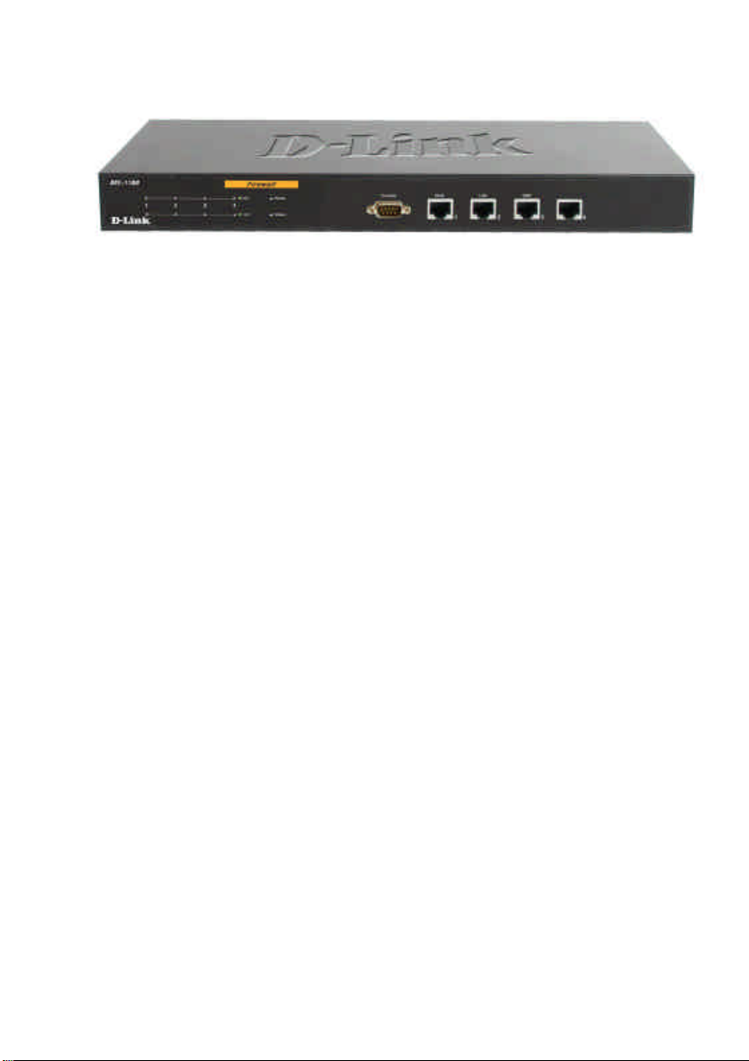
LEDs & Hardware Connections
WAN, LAN, DMZ & ETH4/Sync: Ethernet Link port indicators, Green. The Act LED
flickers when the ports are sending or receiving data.
Power: A solid light indicates a proper connection to the power supply.
Status: System status indicators, flashes to indicate an active system. If the LED has a
solid light please contact technical support.
Console: Serial access to the firewall software, 9600, 8bit, None Parity, 1Stop bit.
External Port (WAN): Use this port to connect to the external router, DSL modem, or
cable modem.
Internal Ports (LAN): Use this port to connect to the internal network of the office.
DMZ Port: Use this port to connect to the company’s server(s), which needs direct
connection to the Internet (FTP, SNMP, HTTP and DNS).
ETH4/Sync Port: Use this port as an extra LAN or DMZ port, or when using High
Availability as the Sync interface.
8
Page 9
Package Contents
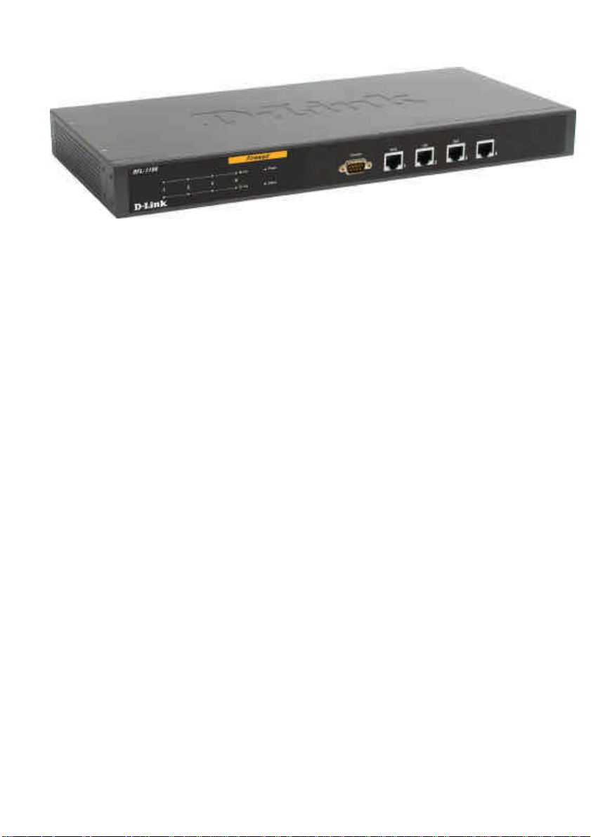
Contents of Package:
• D-Link NETDEFEND DFL-1100 Firewall
• Manual and CD
• Power cord
• Installation Guide – Mini Manual
• CAT5 - Straight-through
• CAT5 - Crossover
If any of the above items are missing, please contact your reseller.
System Requirements
• Computer with a Windows, Macintosh, or Unix based operating system with an
installed Ethernet adapter
• Internet Explorer or Netscape Navigator, version 6.0 or above, with JavaScript
enabled.
Page 10
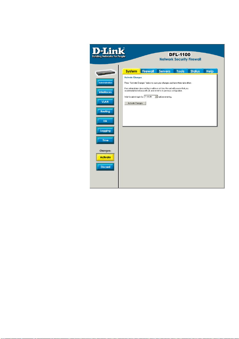
Important Note about Managing the D-Link NETDEFEND DFL-1100
When a change is made to
the configuration, a new icon
named Activate Changes
will appear. When all changes
have been made, click Activate
Changes on the Activate
Configuration Changes page.
The DFL-1100 will save the
configuration, reload it, and the
new changes will take effect.
For the change to become
permanent, the admin needs to
login again. This needs to be
done before the configurable
timeout has been reached; this
can be set on the Activate
Configuration Changes page,
by choosing the time from the
dropdown menu.
10
Page 11
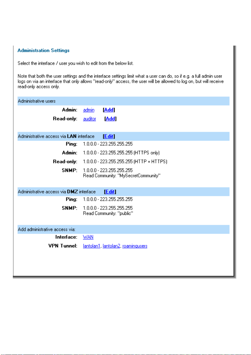
Administration Settings
Administrative Access
Ping – If enabled, specifies who can ping the interface IP of the NETDEFEND DFL-1100.
The default setting allows anyone to ping the interface IP.
Admin – If enabled allows all users with admin access to connect to the DFL-1100 and
change the configuration, which can be HTTPS or HTTP and HTTPS.
Read-Only – If enabled allows all users with read-only access to connect to the DFL-1100
and look at the configuration, which can be HTTPS or HTTP and HTTPS.
Page 12
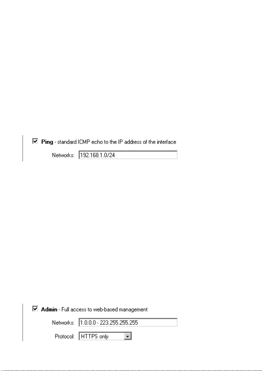
SNMP – Specifies if SNMP should be allowed or not on the interface, the DFL-1100
supports read-only access.
Add ping access to an interface
Follow these steps to add ping access to an interface.
Step 1. Click on the interface to which you would like to add ping access.
Step 2. Enable the Ping checkbox.
Step 3. Specify what networks are allowed to ping the interface, for example
192.168.1.0/24 for a whole network or 172.16.0.1 – 172.16.0.10 for a range.
Click Apply to apply the setting, or click Cancel to discard the changes.
Example:
Add Admin access to an interface
To add admin access to an interface, click on that interface. Only users with administrator
rights can login on interfaces where admin access only is enabled.
Follow these steps to add admin access to an interface.
Step 1. Click on the interface to which you would like to add admin access.
Step 2. Enable the Admin checkbox.
Step 3. Specify what networks are allowed to access the interface, for example
192.168.1.0/24 for a whole network or 172.16.0.1 – 172.16.0.10 for a range.
Step 4. Specify the protocol used to access the DFL-1100 from the dropdown menu,
either HTTP and HTTPS (Secure HTTP) or only HTTPS.
Click Apply to apply the setting or click Cancel to discard the changes.
Example:
12
Page 13
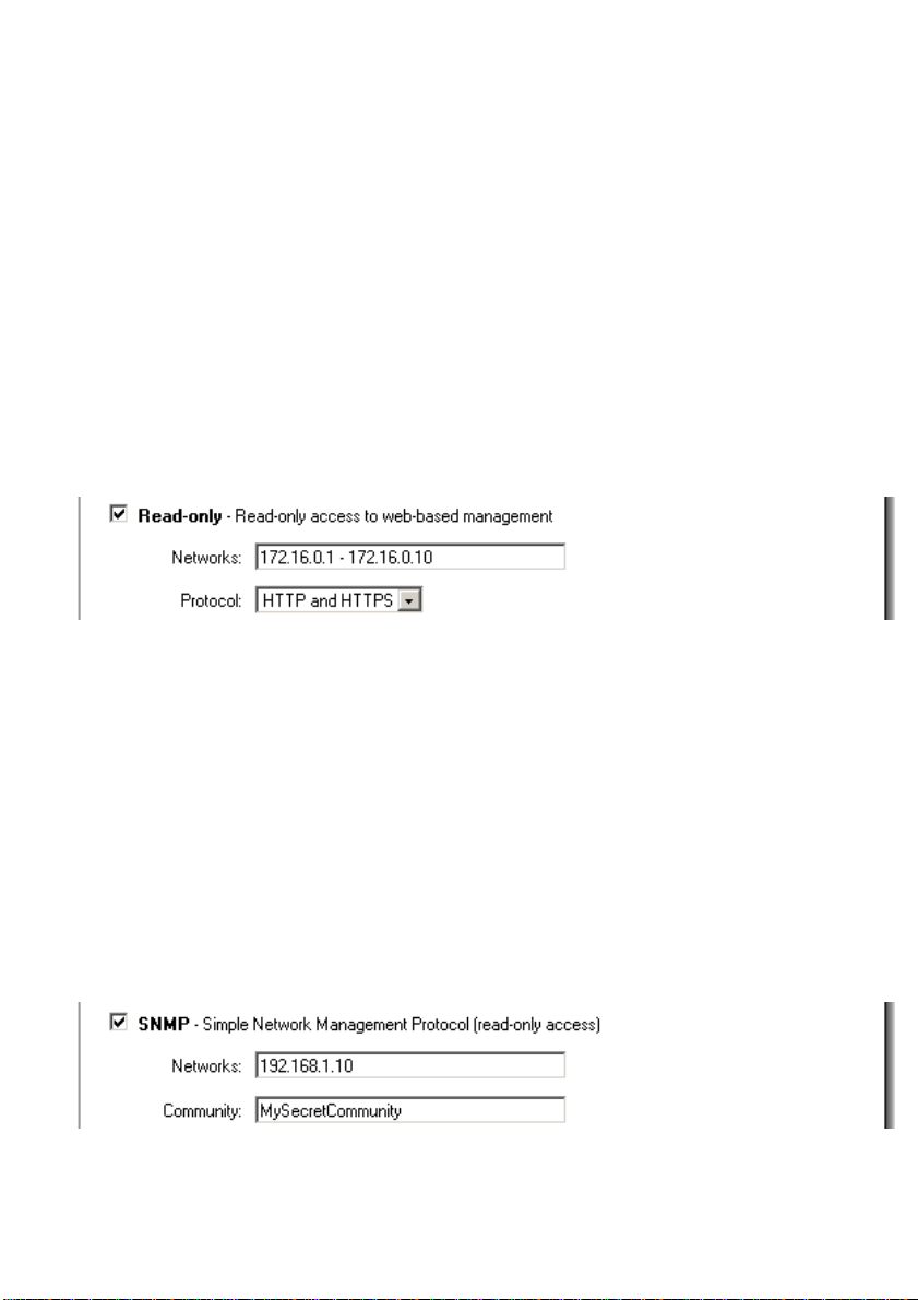
Add Read-only access to an interface
Note that if you have read-only access enabled on an interface, all users will get read-only
access, even if they are administrators.
Follow these steps to add read-only access to an interface.
Step 1. Click on the interface.
Step 2. Enable the Read-only checkbox.
Step 3. Specify which networks are allowed to access the interface, for example
192.168.1.0/24 for a whole network, or 172.16.0.1 – 172.16.0.10 for a range.
Step 4. Specify the protocol used to access the DFL-1100 from the dropdown menu, both
HTTP and HTTPS (Secure HTTP), or only HTTPS.
Click the Apply button to apply the setting, or click Cancel to discard the changes.
Example:
Enable SNMP access to an interface
Follow these steps to add read-only SNMP access to an interface.
Step 1. Click on the interface to which you would like to add it.
Step 2. Enable the Read-only checkbox.
Step 3. Specify what network addresses are allowed to receive SNMP Traps, for example
192.168.1.0/24 for a whole network or 172.16.0.1 – 172.16.0.10 for a range.
Step 4. Specify the community string used to authenticate against the DFL-1100.
Click the Apply button to apply the setting, or click Cancel to discard the changes.
Page 14
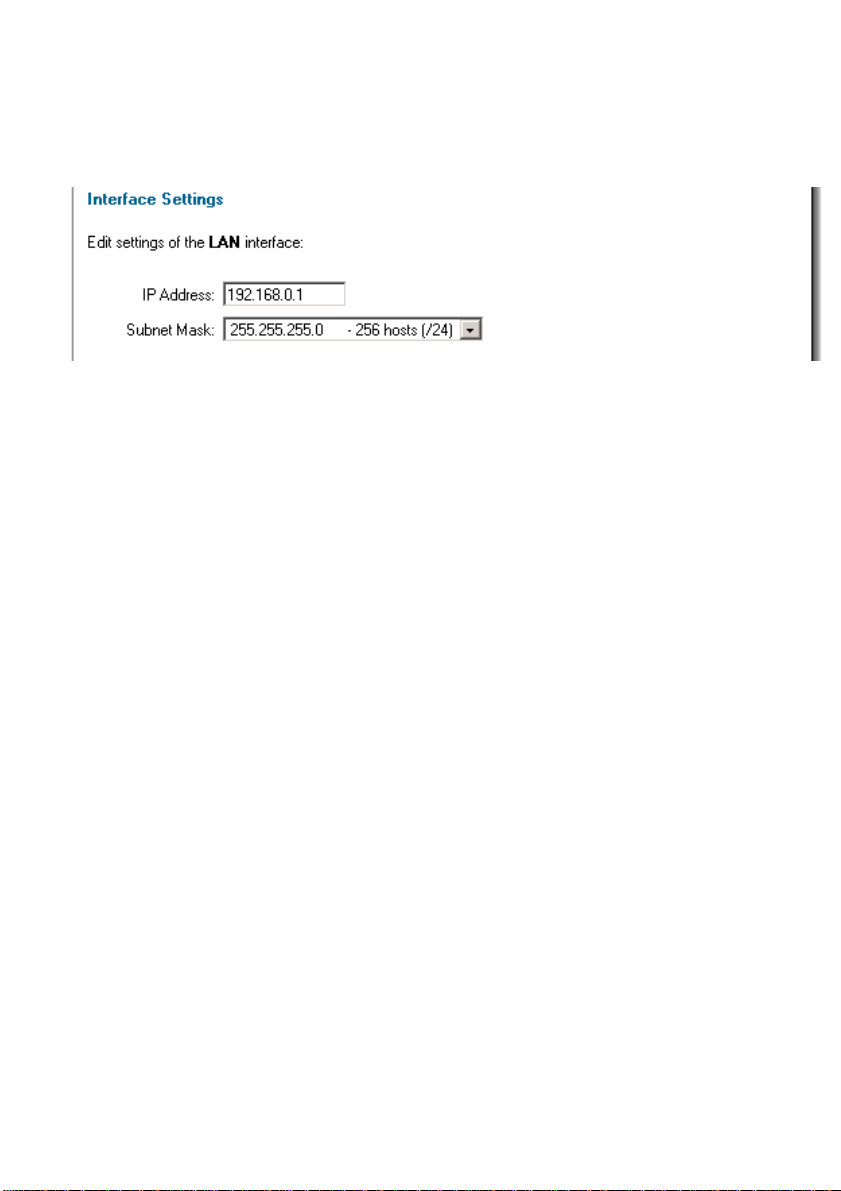
System
Interfaces
Click on System in the menu bar, and then click interfaces below it.
Change the IP of the LAN, DMZ or ETH4 interface
Follow these steps to change the IP of the LAN or DMZ interface.
Step 1. Choose which interface to view or change under the Available interfaces list.
Step 2. Fill in the IP address of the LAN, DMZ or ETH4 interface. These are the
addresses that will be used to ping the firewall, remotely control it, use as a gateway for
the internal hosts or DMZ hosts.
Step 3. Choose the correct subnet mask of this interface from the dropdown menu.
Click Apply to apply the setting, or click Cancel to discard the changes.
14
Page 15
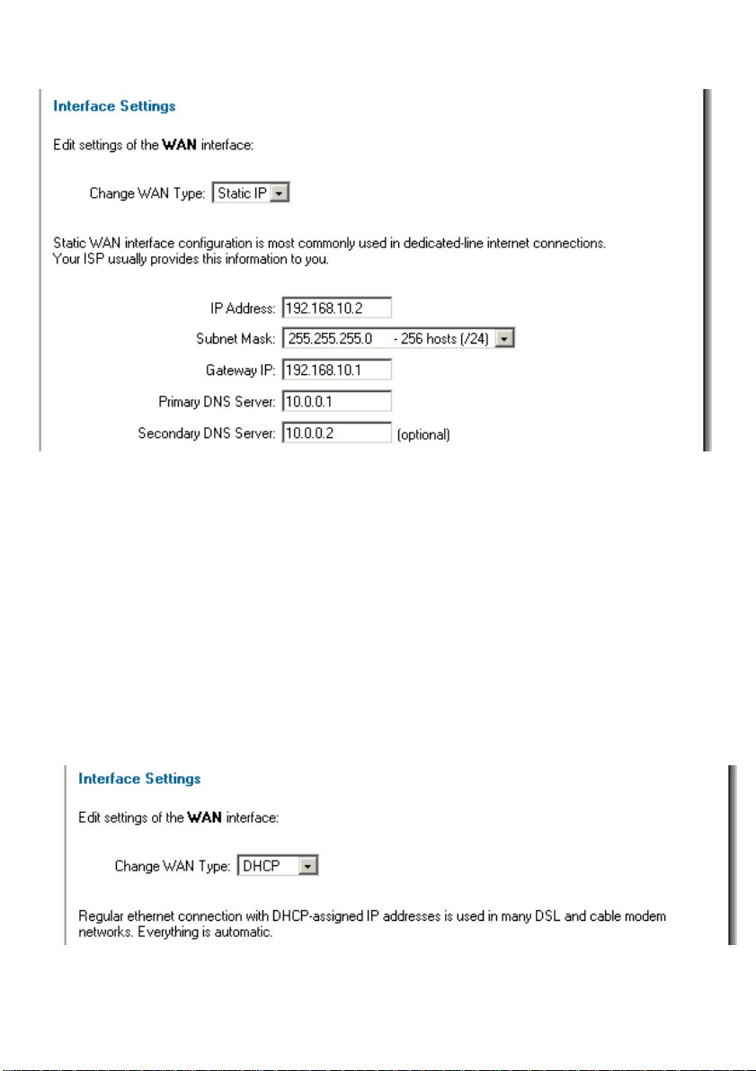
WAN Interface Settings – Using Static IP
If you are using Static IP you must fill in the IP address information provided to you by your
ISP. All fields are required except the Secondary DNS Server. The numbers displayed in
these fields are used only as examples.
• IP Address – The IP address of the WAN interface. This is the address that may
be used to ping the firewall, remotely control it, and as a source address for
dynamically translated connections.
• Subnet Mask – Network and subnet identifier.
• Gateway IP – Specifies the IP address of the default gateway used to reach for
the Internet.
• Primary and Secondary DNS Server – The IP addresses of your DNS servers,
only the Primary DNS is required.
WAN Interface Settings – Using DHCP
If you are using DHCP, there is no need to enter any values in any of the fields.
Page 16
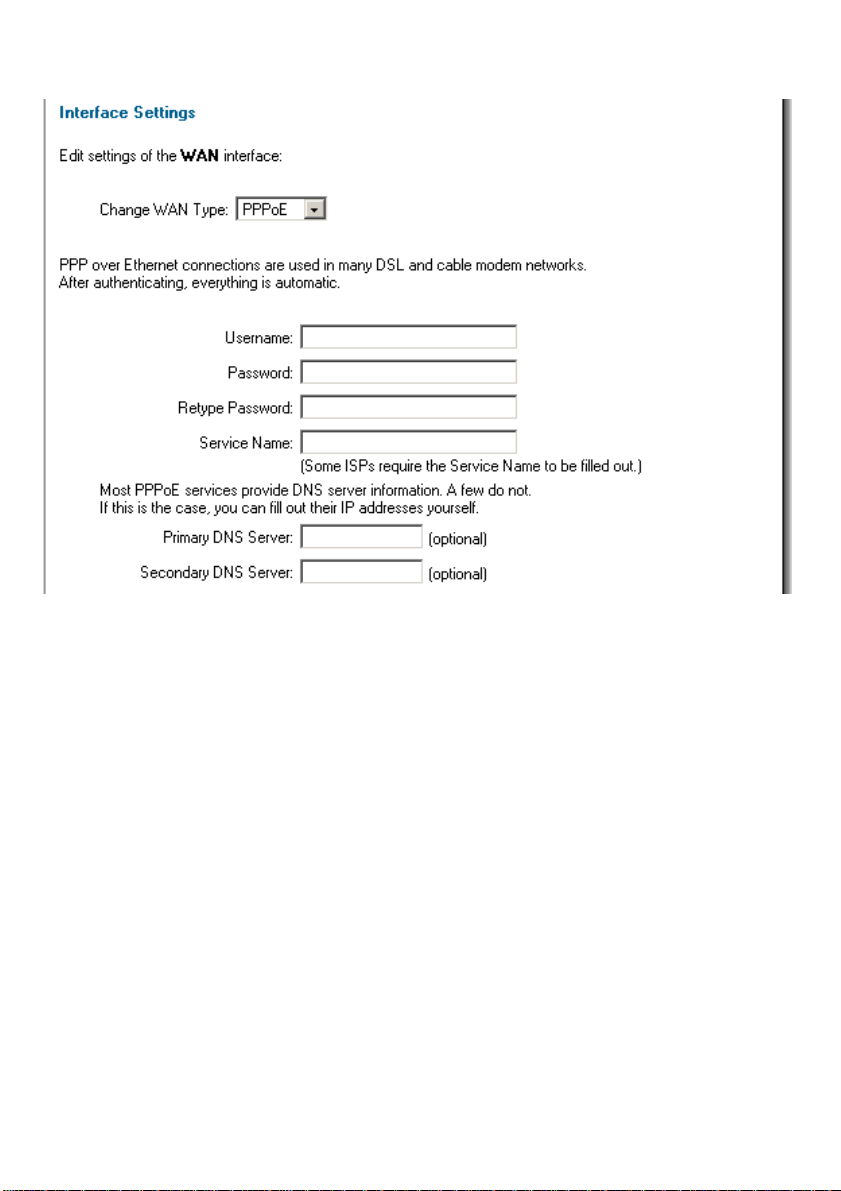
WAN Interface Settings – Using PPPoE
Use the following procedure to configure the NETDEFEND DFL-1100 external interface to use
PPPoE (Point-to-Point Protocol over Ethernet). This configuration is required if your ISP uses
PPPoE to assign the IP address of the external interface. Please enter the username and
password provided to you by your ISP.
• Username – The login or username supplied to you by your ISP.
• Password –The password supplied to you by your ISP.
• Service Name – When using PPPoE, some ISPs require you to fill in a Service
Name.
• Primary and Secondary DNS Server – The IP addresses of your DNS servers,
these are optional and are often provided by the PPPoE service.
16
Page 17
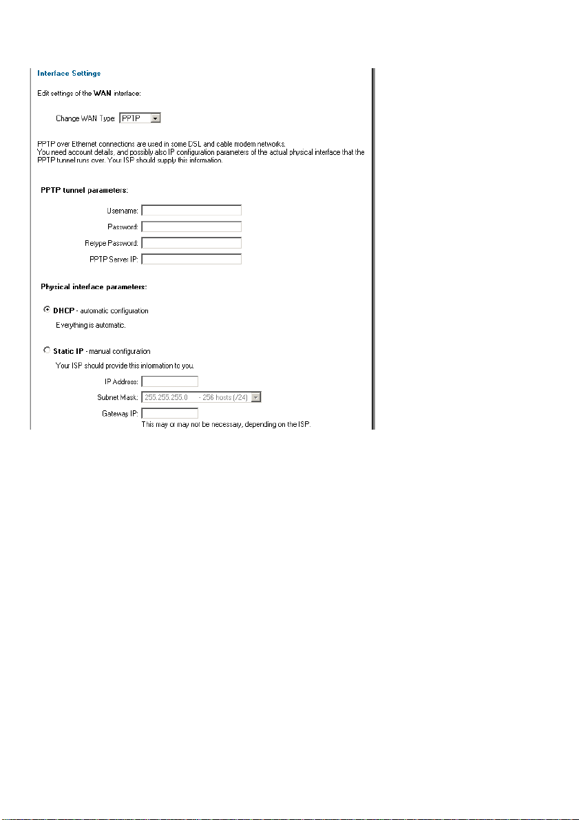
WAN Interface Settings – Using PPTP
PPTP over Ethernet connections are used in some DSL and cable modem networks.
You will need your account details, and you may also need the IP configuration parameters of
the actual physical interface of the PPTP tunnel. Your ISP will supply you with this information.
• Username – The login or username supplied to you by your ISP.
• Password – The password supplied to you by your ISP.
• PPTP Server IP – The IP address of the PPTP server that connects to the
NETDEFEND DFL-1100.
Before PPTP can be used to connect to your ISP, the physical (WAN) interface parameters
need to be supplied. It’s possible to use either DHCP or Static IP depending on the type of
ISP used. This information will be supplied by your ISP.
If you are using static IP, please enter the following information.
• IP Address – The IP address of the WAN interface. This IP is used to connect to
the PPTP server.
• Subnet Mask – Size of the external network.
• Gateway IP – Specifies the IP address of the default gateway used to access the
Internet.
Page 18
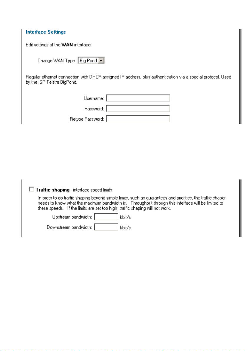
WAN Interface Settings – Using BigPond
The ISP Telstra BigPond uses BigPond for authentication; the IP is assigned with DHCP.
• Username – The login or username supplied to you by your ISP.
• Password – The password supplied to you by your ISP.
Traffic Shaping
When Traffic Shaping is enabled, and the correct maximum up and downstream bandwidth
is specified, it’s possible to control which policies have the highest priority when large
amounts of data are moving through the NETDEFEND DFL-1100. For example, the policy for
the web server might be given higher priority than the policies for most employees' computers.
You can use traffic shaping to guarantee the amount of bandwidth available through the
firewall for a policy; this will ensure that there is enough bandwidth available for a high-priority
service. You can also use traffic shaping to limit the amount of bandwidth available through
the firewall for a policy; in this way, you can keep less important services from using
bandwidth needed for more important services.
Note: If the limit is set too high, i.e. higher then your Internet connection, the traffic shaping
will not work at all.
18
Page 19
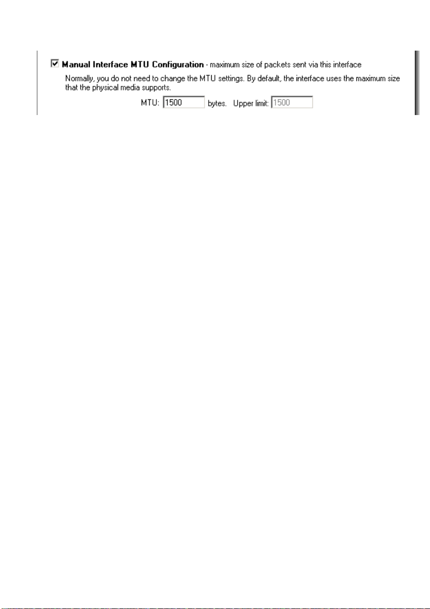
MTU Configuration
To improve the performance of your Internet connection, you can adjust the maximum
transmission unit (MTU) of the packets that the NETDEFEND DFL-1100 transmits from its
external interface. Ideally, you want this MTU to be the same as the smallest MTU of all the
networks between the DFL-1100 and the Internet. If the packets the DFL-1100 sends are
larger, they get broken up or fragmented, which could slow down transmission speeds.
Trial and error is the only sure way of finding the optimal MTU, but there are some guidelines
that can help. For example, the MTU of many PPPoE connections is 1480, so if you connect
to the Internet via PPPoE, you might want to set the MTU size between 1400 and 1480. DSL
modems may also have small MTU sizes. Most Ethernet networks have an MTU of 1500.
Note: If you connect to your ISP using DHCP to obtain an IP address for the external
interface, you cannot set the MTU below 576 bytes due to DHCP communication
standards.
Click Apply to apply the setting, or click Cancel to discard the changes.
Page 20
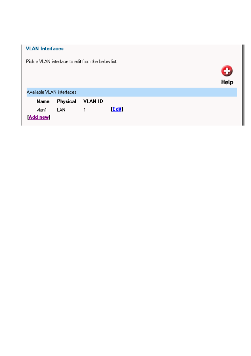
VLAN
Click on System in the menu bar, and then click VLAN below it, this will give a list of all
configured VLANs, it will look something like this:
Add a new VLAN
Follow these steps to add a new VLAN.
Step 1. Go to System and VLAN.
Step 2. Click on Add new in the bottom of the routing table.
Step 3. Choose the interface for the VLAN from the dropdown menu.
Step 4. Specify the 801.2Q VLAN ID.
Step 5. Fill in the IP address of the VLAN interface. This is the address that will be used to
ping the firewall, remotely control it and be used as a gateway for hosts on the VLAN.
Step 6. Choose the correct subnet mask of this interface from the dropdown menu.
Click Apply to apply the setting, or click Cancel to discard the changes.
Remove a VLAN
Follow these steps to add or remove a VLAN.
Step 1. Go to System and VLAN.
Step 2. Click Edit next to the VLAN you would like to remove.
Step 3. Select Delete this VLAN.
Click Apply to apply the setting, or click Cancel to discard the changes.
20
Page 21
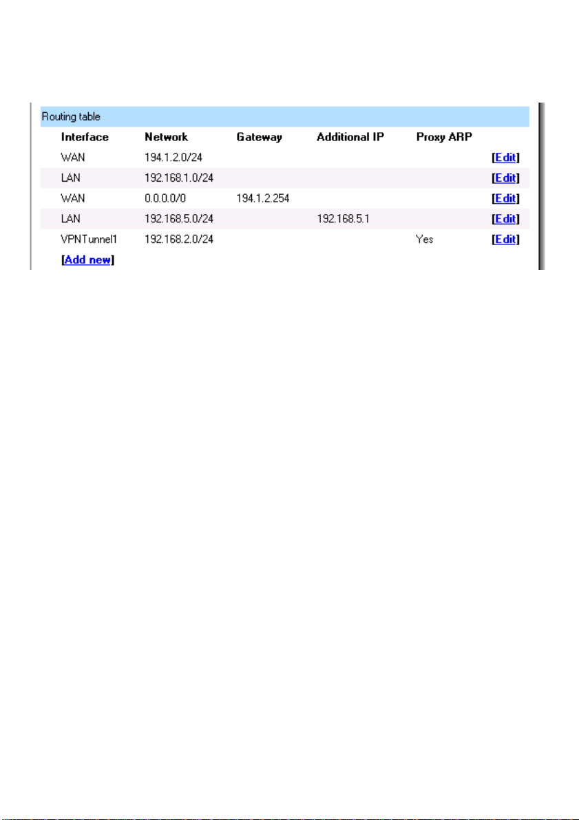
Routing
Click on System in the menu bar, and then click Routing, this will give a list of all configured
routes, it will look something like this:
The Routing configuration section shows the firewall’s routing table. DFL-1100 has an easy to
use interface.
Interface – Specifies the interface through which packets will be sent.
Network – Specifies the network address for this route.
Gateway – Specifies the IP address of the next router hop used to reach the destination
network. If the network is directly connected to the firewall interface, no gateway address
is specified.
Local IP Address – The IP address specified here will be automatically published on the
corresponding interface. This address will also be used as the sender address in ARP
queries. If no address is specified, the firewalls own interface IP address will be used.
Proxy ARP – Specifies that the firewall shall publish this route via Proxy ARP.
One advantage with this form of notation is that you can specify a gateway for a particular
route, without having a route that covers the gateway’s IP address or despite the fact that
the route that covers the gateway’s IP address is normally routed via another interface.
The difference between this form of notation and that most commonly used is that you do
not specify the interface name in a separate column. Instead, you specify the IP address
of each interface as a gateway.
Note: The firewall does not create Proxy ARP routes on VPN interfaces.
Page 22

Add a new Static Route
Follow these steps to add a new route.
Step 1. Go to System and Routing.
Step 2. Click on Add new in the bottom of the routing table.
Step 3. Choose the interface that the route should be sent through from the dropdown
menu.
Step 4. Specify the network and subnet mask.
Step 5. If this network is behind a remote gateway, select Network is behind remote
gateway and specify the IP of that gateway.
Click Apply to apply the setting, or click Cancel to discard the changes.
Remove a Static Route
Follow these steps to remove a route.
Step 1. Go to System and Routing.
Step 2. Click Edit at the route you would like to remove.
Step 3. Select Delete this route.
Click Apply to apply the setting, or click Cancel to discard the changes.
22
Page 23

High Availability
D-Link High Availability works by adding a back-up firewall to your existing firewall. The backup firewall has the same configuration as the primary firewall. It will stay inactive, monitoring
the primary firewall, until it deems that the primary firewall is no longer functioning, at which
point it will go active and assume the active role in the cluster. When the other firewall comes
back up, it will assume a passive role, monitoring the now active firewall.
What High Availability will do for you
D-Link High Availability will provide a redundant, state-synchronized firewalling solution. This
means that the state of the active firewall, i.e., the connection table and other vital information,
is continuously copied to the inactive firewall. When the cluster fails over to the inactive
firewall, it knows which connections are active, and communication may continue to flow
uninterrupted.
The failover time is typically about one second; well in the scope for the normal TCP
retransmit timeout, which is normally over one minute. Clients connecting through the firewall
will merely experience the failover procedure as a slight burst of packet loss, and, as TCP
always does in such situations, retransmit the lost packets within a second or two, and go on
communicating.
What High Availability will NOT do for you
Adding redundancy to your firewall setup will eliminate one of the single points of failure in
your communication path. However, it is not a panacea for all possible communication failures.
Typically, your firewall is far from the only single point of failure. Redundancy for your routers,
switches, and your Internet connection are also issues that need to be addressed.
D-Link High Availability clusters will not create a load-sharing cluster. One firewall will be
active, and the other will be inactive.
Multiple back-up firewalls cannot be used in a cluster. Only two firewalls, a "master" and a
"slave", are supported.
As is the case with all other firewalls supporting stateful failover, the D-Link High Availability
will only work between two D-Link DFL-1100 Firewalls. As the internal workings of different
firewalls, and, indeed, different major versions of the same firewall, can be radically different,
there is no way of communicating "state" to something which has a completely different
comprehension of what "state" means.
Page 24

IP Addresses explained
For each cluster interface, there are three IP addresses:
• Two "real" IP addresses; one for each firewall. These addresses are used to
communicate with the firewalls themselves, i.e., for remote control and
monitoring. They should not be associated in any way with traffic flowing through
the cluster; if either firewall is inoperative, the associated IP address will simply
be unreachable.
• One "virtual" IP address; shared between the firewalls. This is the IP address to
use when configuring default gateways and other routing related matters. It is
also the address used by dynamic address translation, unless the configuration
explicitly specifies another address.
There is not much to say about the real IP addresses; they will act just like firewall interfaces
normally do. You can ping them or remote control the firewalls through them if your
configuration allows it. ARP queries for the respective addresses are answered by the firewall
that owns the IP address, using the normal hardware address, just like normal IP units do.
Note: You must have a static IP address to use HA.
The shared IP address and the failover mechanism
Both firewalls in the cluster know about the shared IP address. ARP queries for the shared IP
address, or any other IP address published via the ARP configuration section or through
Proxy ARP, will be answered by the active firewall.
The hardware address of the shared IP address, and other published addresses for that
matter, is not related to the hardware addresses of the firewall interfaces. Rather, it is
constructed from the cluster ID, on the following form: 10-00-00-C1-4A-nn, where nn is the
Cluster ID configured in the Settings section.
As the shared IP address always has the same hardware address, there will be no latency
time in updating ARP caches of units attached to the same LAN as the cluster when failover
occurs.
When a firewall discovers that its peer is no longer operational, it will broadcast a number of
ARP queries for itself, using the shared hardware address as sender address, on all
interfaces. This causes switches and bridges to re-learn where to send packets destined for
the shared hardware address in a matter of milliseconds.
Hence, the only real delay in the failover mechanism is detecting that a firewall is no longer
operational.
The activation messages (ARP queries) described above are also broadcast periodically to
ensure that switches won't forget where to send packets destined for the shared hardware
address.
24
Page 25

Cluster heartbeats
A firewall detects that its peer is no longer operational when it can no longer hear "cluster
heartbeats" from its peer.
Currently, a firewall will send five cluster heartbeats per second.
When a firewall has "missed" three heartbeats, i.e., after 0.6 seconds, it will be declared
inoperative.
Cluster heartbeats have the following characteristics:
• The source IP is the interface address of the sending firewall
• The destination IP is the shared IP address
• The IP TTL is always 255. If a firewall receives a cluster heartbeat with any other
TTL, it is assumed that the packet has traversed a router, and hence cannot be
trusted at all.
• It is an UDP packet, sent from port 999, to port 999.
• The destination MAC address is the ethernet multicast address corresponding to
the shared hardware address, i.e., 11-00-00-C1-4A-nn. Link-level multicasts were
chosen over normal unicast packets for security reasons. Using unicast packets
would have meant that a local attacker could fool switches to route the
heartbeats somewhere else, causing the peer firewall to never hear the
heartbeats.
The synchronization interface
Both firewalls are connected to each other by a separate synchronization connection; the
fourth port is dedicated solely for this purpose when the firewalls are configured as HA.
The active firewall continuously sends state update messages to its peer, informing it of
connections that are opened, connections that are closed, state and lifetime changes in
connections, etc. The configuration is also transferred between the nodes using the
synchronization connection.
When the active firewall ceases to function, for whatever reason and for even a short time, the
cluster heartbeat mechanism described above will cause the inactive firewall to go active.
Since it already knows about all open connections, communication can continue to flow
uninterrupted.
Page 26
Setting up a High Availability cluster
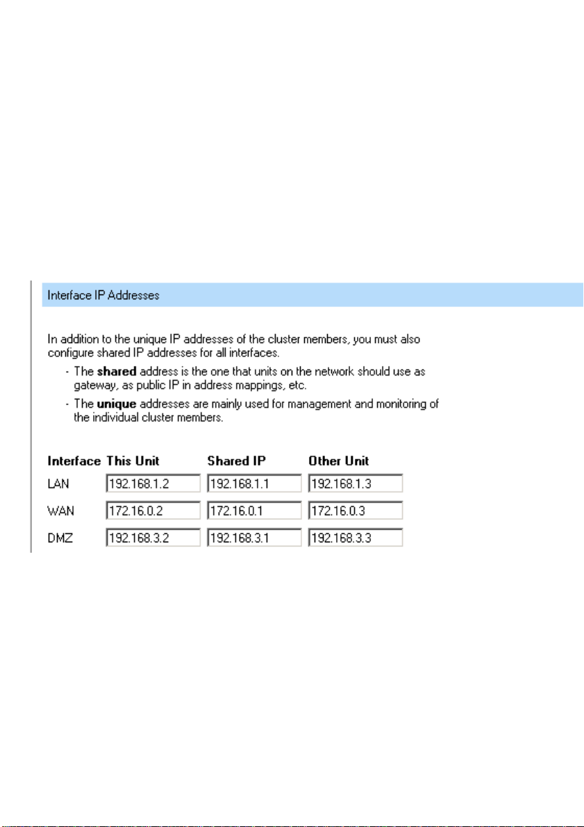
First of all, the two DFL-1100s need to be setup so that you can manage them over the we b
interface. In this example the two units are configured as follows, the master DFL-1100 will be
configured with 192.168.1.2 on its internal interface, and the slave DFL-1100 with 192.168.1.3.
Later when the setup of the HA is done, the virtual or shared IP will be 192.168.1.1 on the
LAN, this is the IP that clients on that network will use as gateway.
When both units are configured with the two individual IPs they should be connected with a
crossover cable between the fourth interfaces on each unit, this interface (ETH4) will not be
available to use as an extra DMZ or LAN interface when running HA.
Login to the master firewall and click on System in the menu bar, and then click HA below it;
in this screen you will click on Configure additional HA parameters. This will show the
screen below; here you will fill in each Unit’s own IP and the shared IP on each interface. This
Unit means the master firewall, the one you should be configuring at the moment. Other Unit
is the slave firewall, the other DFL-1100.
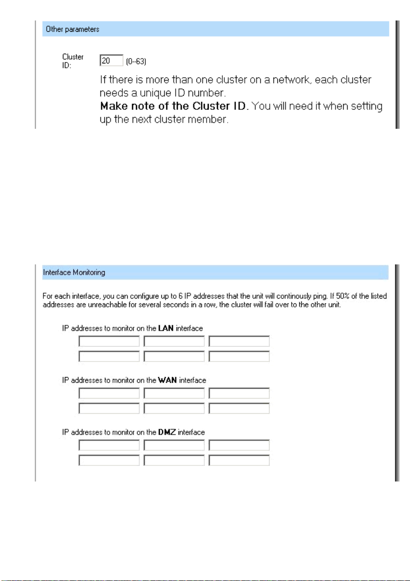
You also need to configure the Cluster ID of the cluster, this has to be a number between 0
and 63, which must be the same on both firewalls in the cluster. This must be unique to your
LAN, if you are running more then one cluster.
26
Page 27
When this is done click Apply.
Now login to the slave firewall and go to System > HA; in this screen you will click on
Receive configuration from first unit. This will show the screen below; here you will fill in
the cluster ID configured on the first unit. When you click Apply the unit should transfer the
configuration from the first unit, and your HA cluster should be operating.
Interface Monitoring
When HA is configured it’s possible to configure something called Interface Monitoring, this is
used to monitor up to 6 IP addresses on each segment (LAN/WAN or DMZ) of the DFL-1100
cluster. If 50% of the listed addresses are unreachable for several seconds, the active node
will failover and the other unit will become active.
Page 28
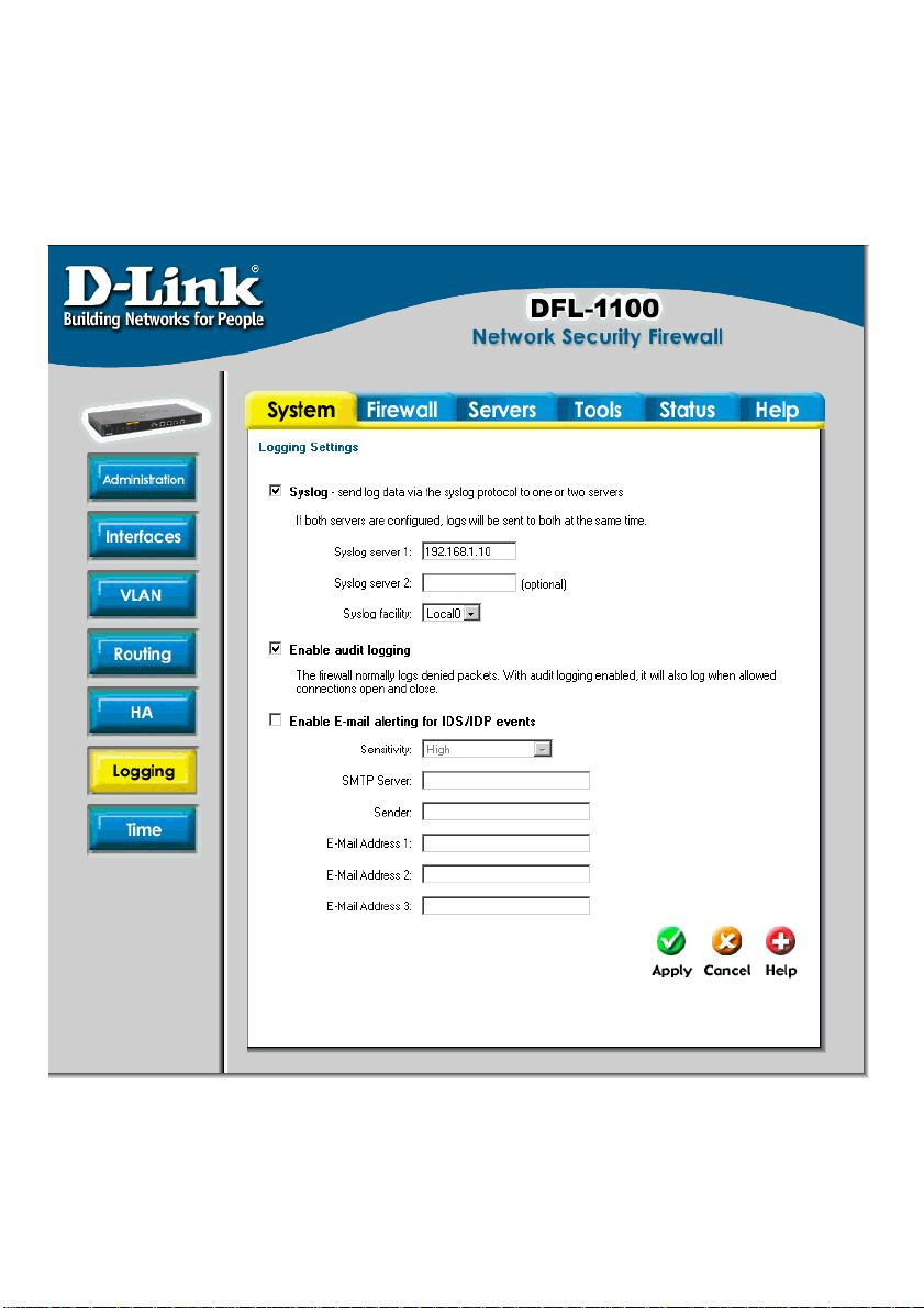
Logging
Click on System in the menu bar, and then click Logging below it.
Logging, the ability to audit decisions made by the firewall, is a vital part in all network security
products. The D-Link NETDEFEND DFL-1100 provides several options for logging its activity.
The D-Link DFL-1100 logs its activities by sending the log data to one or two log receivers in
the network.
All logging is done to Syslog recipients. The log format used for syslog logging is suitable for
automated processing and searching.
The D-Link NETDEFEND DFL-1100 specifies a number of events that can be logged. Some of
these events, such as, startup and shutdown events, are mandatory, and will always generate
log entries. Other events, such as opening and closing allowed connections, can be
28
Page 29

configured to generate log entries. It’s also possible to have E-mail alerting for IDS/IDP events
to up to three email addresses.
Enable Logging
Follow these steps to enable logging.
Step 1. Enable syslog by checking the Syslog box.
Step 2. Fill in your first syslog server as Syslog server 1, if you have two syslog servers
you have to fill in the second one as Syslog server 2. You must fill in at least one syslog
server for logging to work.
Step 3. Specify what facility to use by selecting the appropriate syslog facility. Local0 is
the default facility.
Click Apply to apply the setting, or click Cancel to discard the changes.
Enable Audit Logging
To start auditing all traffic through the firewall, follow the steps below and the firewall will start
logging all traffic through the firewall. This is needed for running third party log analyzers on
the logs, and to see how much traffic different connections use.
Follow these steps to enable auditing.
Step 1. Enable syslog by checking the Enable audit logging box.
Click Apply to apply the setting, or click Cancel to discard the changes.
Enable E-mail alerting for IDS/IDP events
Follow these steps to enable E-mail alerting.
Step 1. Enable E-mail alerting by checking the Enable E-mail alerting for IDS/IDP
events checkbox.
Step 2. Choose the sensitivity level.
Step 3. In the SMTP Server field, fill in the SMTP server to which the DFL-1100 should
send email.
Step 4. Specify up to three valid email addresses to receive the email alerts.
Click Apply to apply the setting, or click Cancel to discard the changes.
Page 30
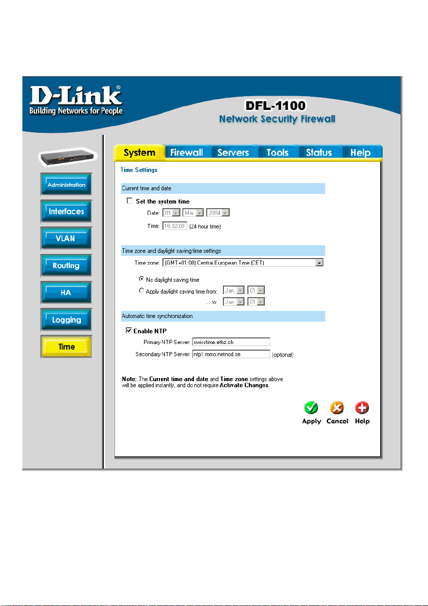
Time
Click on System in the menu bar, and then click Time. This will give you the option to either
set the system time by syncing to an Internet Network Time Server (NTP) or by entering the
system time manually.
30
Page 31

Changing the time zone
Follow these steps to change the time zone.
Step 1. Choose the correct time zone in the dropdown menu.
Step 2. Specify your daylight time or choose no daylight saving time by checking the
correct box.
Click Apply to apply the setting, or click Cancel to discard the changes.
Using NTP to sync time
Follow these steps to sync to an Internet Time Server.
Step 1. Enable synchronization by checking the Enable NTP box.
Step 2. Enter the server IP address or server name with which you want to synchronize.
Click Apply to apply the setting, or click Cancel to discard the changes.
Setting time and date manually
Follow these steps to set the system time manually.
Step 1. Checking the Set the system time box.
Step 2. Choose the correct date.
Step 3. Set the correct time in 24-hour format.
Click Apply to apply the setting, or click Cancel to discard the changes.
Page 32

Firewall
Policy
The Firewall Policy configuration section is very important. These policies are the primary
filters that are configured to allow or disallow certain types of network traffic through the
firewall. The policies also regulate how bandwidth management (traffic shaping) is applied to
traffic flowing through the WAN interface of the firewall.
When a new connection is being established through the firewall, the policies are evaluated,
top to bottom, until a policy that matches the new connection is found. The Action of the rule
is then carried out. If the action is Allow, the connection will be established and a state
representing the connection is added to the firewall's internal state table. If the action is Drop,
the new connection will be refused. The section below will explain the meanings of the various
action types available.
Policy modes
The first step in configuring security policies is to configure the mode for the firewall. The
firewall can run in NAT or No NAT (Route) mode. Select NAT mode to use DFL-1100 network
address translation to protect private networks from public networks. In NAT mode, you can
connect a private network to the internal interface, a DMZ network to the DMZ interface, and a
public network, such as the Internet, to the external interface. Then you can create NAT mode
policies to accept or deny connections between these networks. NAT mode policies hide the
addresses of the internal and DMZ networks from users on the Internet. In No NAT (Route)
mode you can also create routed policies between interfaces. Route mode policies accept or
deny connections between networks without performing address translation. To use NAT
mode select Hide source addresses (many-to-one NAT) and to use No NAT (Route) mode
choose No NAT.
Action Types
Drop – Packets matching Drop rules will immediately be dropped. Such packets will be
logged if logging has been enabled in the Logging Settings page.
Reject – Reject works in basically the same way as Drop. In addition to this, the firewall
sends an ICMP UNREACHABLE message back to the sender or, if the rejected packet
was a TCP packet, a TCP RST message. Such packets will be logged if logging has been
enabled in the Logging Settings page.
Allow – Packets matching Allow rules are passed to the stateful inspection engine, which
will remember that a connection has been opened. Therefore, rules for return traffic will
not be required as traffic belonging to open connections is automatically dealt with before
it reaches the policies. Logging is carried out if audit logging has been enabled in the
Logging Settings page.
Source and Destination Filter
Source Nets – Specifies the sender span of IP addresses to be compared to the received
packet. Leave this blank to match everything.
32
Page 33

Source Users/Groups – Specifies if an authenticated username is needed for this policy
to match. Either make a list of usernames, separated by a comma, or write Any for any
authenticated user. If it’s left blank there is no need for authentication for the policy.
Destination Nets – Specifies the span of IP addresses to be compared to the destination
IP of the received packet. Leave this blank to match everything.
Destination Users/Groups – Specifies if an authenticated username is needed for this
policy to match. Either make a list of usernames, separated by a comma, or write Any for
any authenticated user. If it’s left blank there is no need for authentication for the policy.
Service Filter
Either choose a predefined service from the dropdown menu or make a custom filter.
The following custom services exist:
All – This service matches all protocols.
TCP+UDP+ICMP – This service matches all ports on either the TCP or the UDP protocol,
including ICMP.
Custom TCP – This service is based on the TCP protocol.
Custom UDP – This service is based on the UDP protocol.
Custom TCP+UDP – This service is based on either the TCP or the UDP protocol.
The following is used when making a custom service:
Custom source/destination ports – For many services, a single destination port is
sufficient. The source port most often will be all ports, 0-65535. The http service, for
instance, uses destination port 80. (A port range can also be used, meaning that a range
137-139 covers ports 137, 138 and 139.) Multiple ranges or individual ports may also be
entered, separated by commas. For instance, a service can be defined as having source
ports 1024-65535 and destination ports 80-82, 90-92, 95. In this case, a TCP or UDP
packet with the destination port being one of 80, 81, 82, 90, 91, 92 or 95, and the source
port being in the range 1024-65535, will match this service.
Schedule
If a schedule should be used for the policy, choose one from the dropdown menu. These are
specified on the Schedules page. If the policy should always be active, choose Always from
the dropdown menu.
Intrusion Detection / Prevention
The DFL-1100 Intrusion Detection/Prevention System (IDS/IDP) is a real-time intrusion
detection and prevention sensor that identifies and takes action against a wide variety of
suspicious network activity. The IDS uses intrusion signatures, stored in the attack database,
to identify the most common attacks. In response to an attack, the IDS protects the networks
behind the DFL-1100 by dropping the traffic. To notify of the attacks, the IDS sends an email
to the system administrators, if email alerting has been configured. D-Link updates the attack
database periodically. Signatures are available for download at http://support.dlink.com. There
are two modes that can be configured, either Inspection Only or Prevention. Inspection
Only will only inspect the traffic. If the DFL-1100 sees anything, it will log, email an alert
Page 34

(if configured) and pass on the traffic. If Prevention is used, the traffic will be dropped and
logged, and if configured, an email alert will be sent.
Traffic Shaping
The simplest way to obtain quality of service in a network, seen from a security as well as a
functionality perspective, is to have the components in the network, not the applications, be
responsible for network traffic control in well-defined choke points.
Traffic shaping works by measuring and queuing IP packets, in transit, with respect to a
number of configurable parameters. Differentiated rate limits and traffic guarantees based on
source, destination and protocol parameters can be created; much the same way firewall
policies are implemented.
There are three different priorities when configuring the traffic shaping, Normal, High and
Critical.
Limit works by limiting the inbound and outbound traffic to the specified speed. This is the
maximum bandwidth that can be used by traffic using this policy. Note, however, that if you
have other policies using limit, which in total comprises more then your total Internet
connection, and have configured the traffic limits on the WAN interface, this limit is sometimes
lowered, to allow traffic with higher priorities to have precedence.
By using Guarantee, you can use a policy of minimum bandwidth. This will only work if the
traffic limits for the WAN interface are configured correctly.
Policy Routing
Normal routing can be said to be a simple form of policy based routing; the "policy" is the
routing table, and the only data that can be filtered on is the destination IP address of the
packet. What is commonly referred to as policy based routing, is, simply put, an extension of
what fields of the packet we look at to determine the routing decision. In the DFL-1100, each
rule in the firewall policy can specify its own routing decision; in essence, we route according
to the source and destination IP addresses and ports.
Policy based routing can for example be used to route certain protocols through transparent
proxies such as web caches and anti-virus scanners, without adding another point of failure
for the network as a whole. It’s very important to know that the proxy must support this also
for it to work.
There are two ways to configure Policy Routing; both include specifying the Gateway to send
the traffic over. The first one, Redirect via routing (make gateway next hop), will just
reroute the traffic to the given gateway as if it was just another router. The second mode, Via
address translation (change destination IP), will change the destination IP, in the IP
header, and then pass the packet on to the gateway. This is used, for example, in transparent
squid-proxy setups.
34
Page 35

Add a new policy
Follow these steps to add a new outgoing policy.
Step 1. Choose the LAN > WAN policy list from the available policy lists.
Step 2. Click on the Add new link.
Step 3. Fill in the following values:
Name: Specifies a symbolic name for the rule. This name is used mainly as a rule
reference in log data and for easy reference in the policy list.
Action: Select Allow to allow this type of traffic.
Source Nets: – Specifies the sender span of IP addresses to be compared to the
received packet. Leave this blank to match everything.
Source Users/Groups: Specifies if an authenticated username is needed for this policy to
match. Either make a list of usernames, separated by a comma, or write Any for any
authenticated user. If it’s left blank there is no need for authentication for the policy.
Destination Nets: Specifies the span of IP addresses to be compared to the destination
IP of the received packet. Leave this blank to match everything.
Destination Users/Groups: Specifies if an authenticated username is needed for this
policy to match. Either make a list of usernames, separated by a comma, or write Any for
any authenticated user. If it’s left blank there is no need for authentication for the policy.
Service: Either choose a predefined service from the dropdown menu or create a custom
service.
Schedule: Choose what schedule should be used for this policy to match, choose Always
for no scheduling.
Step 4. If using Traffic shaping, fill in that information, if not, skip this step.
Click Apply to apply the change, or click Cancel to discard the changes
Page 36

Change order of policy
Follow these steps to change the order of a policy.
Step 1. Choose the policy list.
Step 2. Click on the Edit link on the rule you want to change.
Step 3. Change the number in the Position to the new position. After the apply button is
clicked the policy will be moved to the new position.
Click Apply to apply the chang,e or click Cancel to discard the changes.
Delete policy
Follow these steps to delete a policy.
Step 1. Choose the policy list.
Step 2. Click on the Edit link on the rule you want to delete.
Step 3. Enable the Delete policy checkbox.
Click Apply to apply the change, or click Cancel to discard the changes.
Configure Intrusion Detection
Follow these steps to configure IDS on a policy.
Step 1. Choose the policy.
Step 2. Click on the Edit link on the rule you want to add.
Step 3. Enable the Intrusion Detection / Prevention checkbox.
Step 4. Choose Intrusion Detection from the mode drop down list.
Step 5. Enable the alerting checkbox for email alerting.
Click Apply to apply the change or click Cancel to discard the changes.
36
Page 37

Configure Intrusion Prevention
Follow these steps to configure IDP on a policy.
Step 1. Choose the policy.
Step 2. Click on Edit.
Step 3. Enable the Intrusion Detection / Prevention checkbox.
Step 4. Choose Prevention from the mode drop down list.
Step 5. Enable the alerting checkbox for email alerting.
Click Apply to apply the change, or click Cancel to discard the changes.
Page 38

Port mapping / Virtual Servers
The Port mapping / Virtual Servers configuration section is where you can configure virtual
servers, like Web servers. It’s also possible to regulate how bandwidth management, traffic
shaping, is applied to traffic flowing through the WAN interface of the firewall. It is also
possible to use Intrusion Detection / Prevention and Traffic shaping on Port mapped services.
Since this is done in the same way as policies, please see that chapter for more information.
Mappings are read from top to bottom, and the first matching mapping is carried out.
Add a new mapping
Follow these steps to add a new mapping on the WAN interface.
Step 1. Choose the WAN policy list from the available policy lists.
Step 2. Click on the Add new link.
Step 3. Fill in the following values:
Name: Specifies a symbolic name for the rule. This name is used mainly as a rule
reference in log data and for easy reference in the policy list.
Source Nets: Specify the source networks, leave blank for everyone (0.0.0.0/0).
Source Users/Groups: Specifies if an authenticated username is needed for this
mapping to match. Either make a list of usernames, separated by a comma, or write Any
for any authenticated user. If it’s left blank there is no need for authentication for the policy.
Destination Nets: Leave empty for the interfaces own IP or enter a new IP if using Virtual
IP.
Service: Either choose a predefined service from the dropdown menu or make a custom
service.
Pass To: The IP of the server that the traffic should be passed to.
Schedule: Choose the schedule to be used for this mapping to match, choose Always for
no scheduling.
Step 4. If using Traffic shaping, fill in that information, if not skip, this step.
Click Apply to apply the change or click Cancel to discard the changes.
38
Page 39

Delete mapping
Follow these steps to delete a mapping.
Step 1. Choose the mapping list (WAN, LAN or DMZ)
Step 2. Click on Edit.
Step 3. Enable the Delete mapping checkbox.
Click Apply to apply the change, or click Cancel to discard the changes.
Page 40
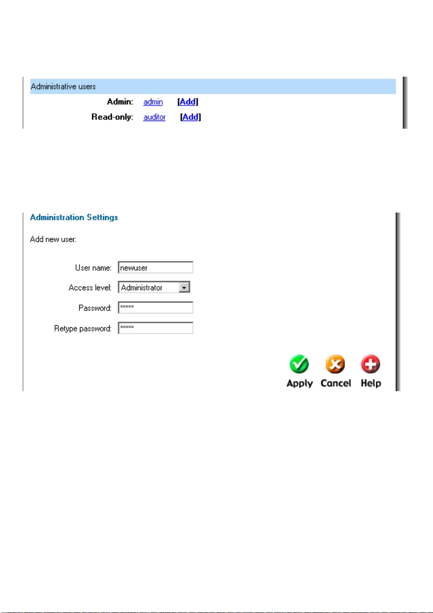
Administrative users
Click on Firewall in the menu bar, and then click Users below it. This will show all the users.
The first section is the administrative users.
The first column shows the access levels, Administrator and Read-only. An Administrator user
can add, edit and remove rules, change settings of the DFL-1100 and so on. The Read-only
user can only look at the configuration. The second column shows the users in each access
level.
Add Administrative User
Follow these steps to add a new administrative user.
Step 1. Click on add after the type of user you would like to add, Admin or Read-only.
Step 2. Fill in the User name; make sure you are not trying to add one that already exists.
Step 3. Specify the password for the new user.
Click Apply to apply the setting or click Cancel to discard the changes.
Note: The user name and password should be at least six characters long. The user
name and password can contain numbers (0-9) and upper and lower case letters (A-Z, az). Special characters and spaces are not allowed.
40
Page 41
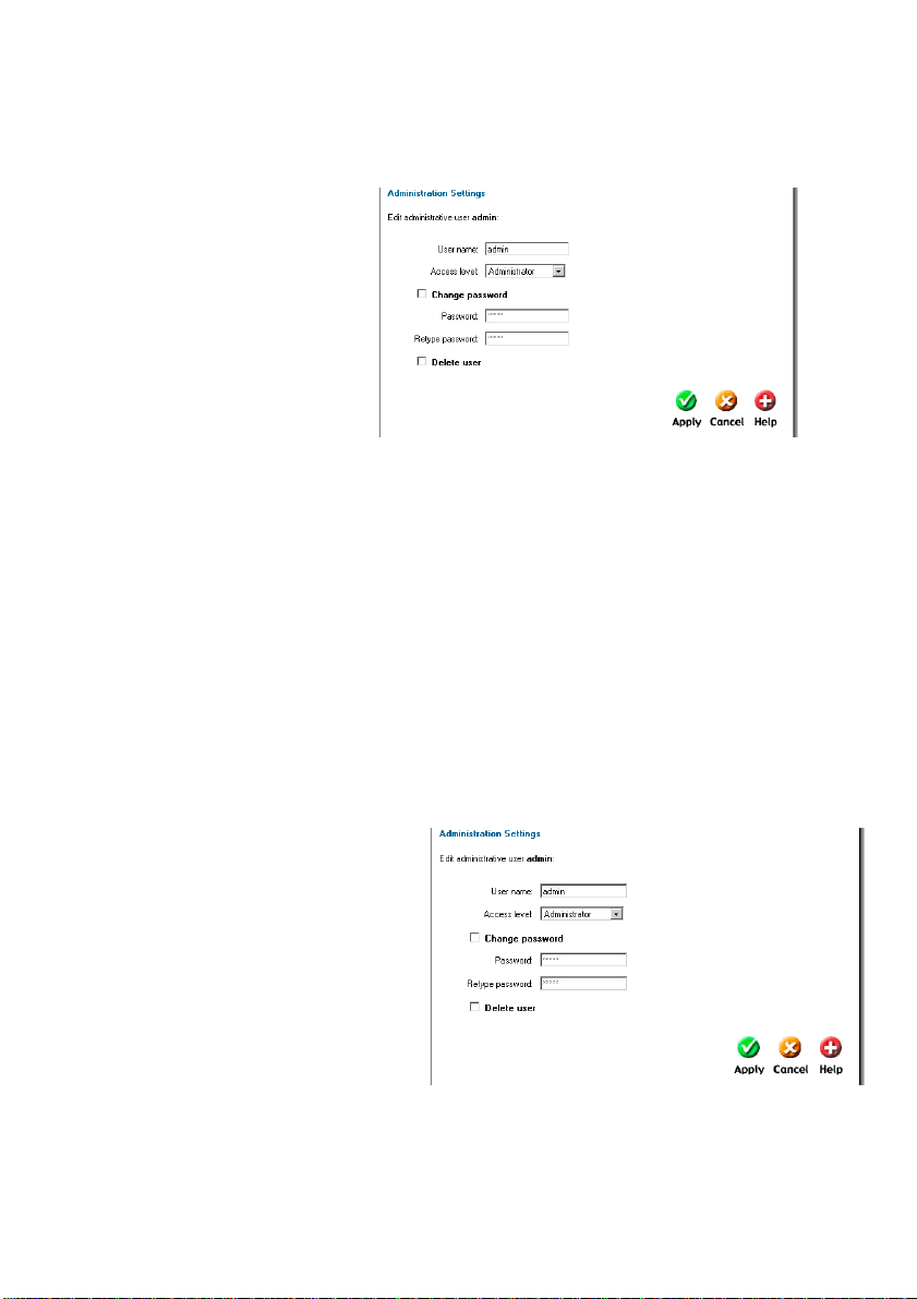
Change Administrative User Access level
To change the access level of a user, click on the user name and you will see the following
screen. From here you can change the access level by choosing the appropriate level from
the drop-down menu.
Access levels
• Administrator – the
user can add, edit and
remove rules and
change all settings.
• Read-only – the user
can only look at the
configuration of the
firewall.
• No Admin Access –
Used for authentication purposes.
Follow these steps to change Administrative User Access level.
Step 1. Click on the user you would like to change.
Step 2. Choose the appropriate level from the drop-down menu.
Click Apply to apply the setting, or click Cancel to discard the changes.
Change Administrative User Password
To change the password of a user click on the user name and you will see the following
screen.
Follow these steps to change the
Administrative User password.
Step 1. Click on the user.
Step 2. Enable the Change
password checkbox.
Step 3. Enter the new password twice.
Click Apply to apply the setting, or
click Cancel to discard the changes.
Note: The password should be at least six characters long. The password can contain
numbers (0-9) and upper and lower case letters (A-Z, a-z). Special characters and spaces
are not allowed.
Page 42
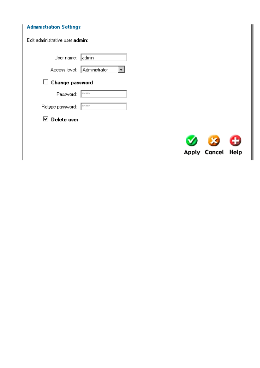
Delete Administrative User
To delete a user, click on the user name, and you will see the following screen.
Follow these steps to delete an Administrative User.
Step 1. Click on the user.
Step 2. Enable the Delete user checkbox.
Click Apply to apply the setting, or click Cancel to discard changes.
Note: Deleting a user is irreversible; once the user is deleted, it cannot be undeleted.
Do not delete your currently logged in user name.
42
Page 43

Users
User Authentication allows an administrator to grant or reject access to specific users from
specific IP addresses, based on their user credentials.
Before any traffic is allowed to pass through any policies configured with username or groups,
the users must first be authenticated. The DFL -1100 can either verify the user against a local
database, or pass along the user information to an external authentication server. This server
will verify the user and the given password, and transmit the results back to the firewall. If the
authentication is successful, the DFL-1100 will remember the source IP address of this user,
and any matching policies with usernames or groups configured will be allowed. Specific
policies that deal with user authentication can be defined, thus leaving policies that do not
require user authentication unaffected.
The DFL-1100 supports the RADIUS (Remote Authentication Dial In User Service)
authentication protocol. This protocol is heavily used in many scenarios where user
authentication is required, either by itself or as a front-end to other authentication services.
The DFL-1100 RADIUS Support
The DFL-1100 can use the RADIUS server to verify users against the Active Directory or Unix
password-file. It is possible to configure up to two servers; if the first one is down it will try the
second IP instead.
The DFL-1100 can use CHAP or PAP when communicating with the RADIUS server. CHAP
(Challenge Handshake Authentication Protocol) does not allow a remote attacker to extract
the user password from an intercepted RADIUS packet. However, the password must be
stored in plaintext on the RADIUS server. PAP (Password Authentication Protocol) might be
defined as the less secure of the two. If a RADIUS packet is intercepted while being
transmitted between the firewall and the RADIUS server, the user password can be extracted,
given time. The upside to this is that the password does not have to be stored in plaintext in
the RADIUS server.
The DFL-1100 uses a shared secret when connecting to the RADIUS server. The shared
secret enables basic encryption of the user password when the RADIUS-packet is transmitted
from the firewall to the RADIUS server. The shared secret is case sensitive, can contain up to
100 characters, and must be typed exactly the same on both the firewall and the RADIUS
server.
Page 44
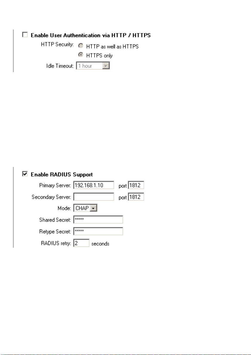
Enable User Authentication via HTTP / HTTPS
Follow these steps to enable User Authentication.
Step 1. Enable the checkbox for User Authentication.
Step 2. Specify if HTTP and HTTPS or only HTTPS should be used for the login.
Step 3. Specify the idle-timeout, the time a user can be idle before being logged out by the
firewall.
Step 4. Choose new ports.
Click Apply to apply the setting, or click Cancel to discard the changes.
Enable RADIUS Support
Follow these steps to enable RADIUS support.
Step 1. Enable the checkbox for RADIUS Support.
Step 2. Fill in up to two RADIUS servers.
Step 3. Specify which mode to use, PAP or CHAP.
Step 3. Specify the shared secret for this connection.
Click Apply to apply the setting, or click Cancel to discard the changes.
44
Page 45
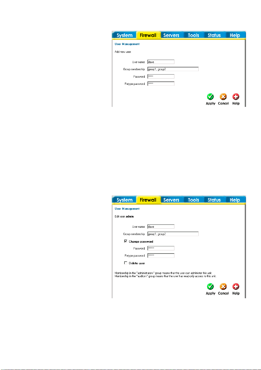
Add User
Follow these steps to add a new user.
Step 1. Click on add after the
type of user you would like to add,
Admin or Read-only.
Step 2. Fill in the User name;
make sure you are not trying to
add one that already exists.
Step 3. Specify what groups the
user should be a member of.
Step 3. Specify the password for the new user.
Click Apply to apply the setting, or click Cancel to discard the changes.
Note: The user name and password should be at least six characters long. The user
name and password can contain numbers (0-9) and upper and lower case letters (A-Z, az). Special characters and spaces are not allowed.
Change User Password
To change the password of a user, click the user name and you will see this screen.
Follow these steps to change a
user’s password.
Step 1. Click on the user.
Step 2. Enable the Change
password checkbox.
Step 3. Enter the new password
twice.
Click Apply to apply the setting,
or click Cancel to discard changes.
Note: The password should be at
least six characters long. The
password can contain numbers
(0-9) and upper and lower case letters (A-Z, a-z). Special characters and spaces are not
allowed.
Page 46
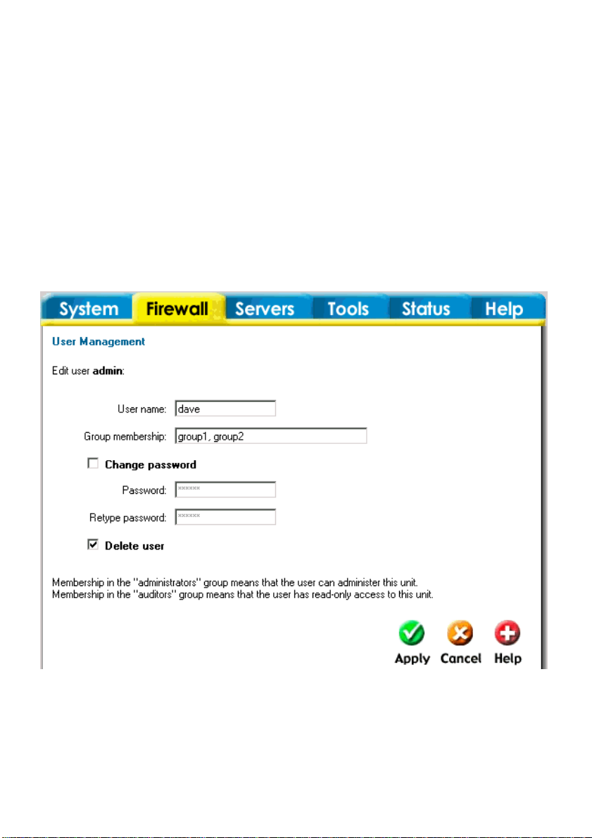
Delete User
To delete a user click on the user name and you will see the following screen.
Follow these steps to delete a user.
Step 1. Click on the user.
Step 2. Enable the Delete user checkbox.
Click Apply to apply the setting, or click Cancel to discard the changes.
Note: Deleting a user is irreversible; once the user is deleted, it cannot be undeleted.
46
Page 47
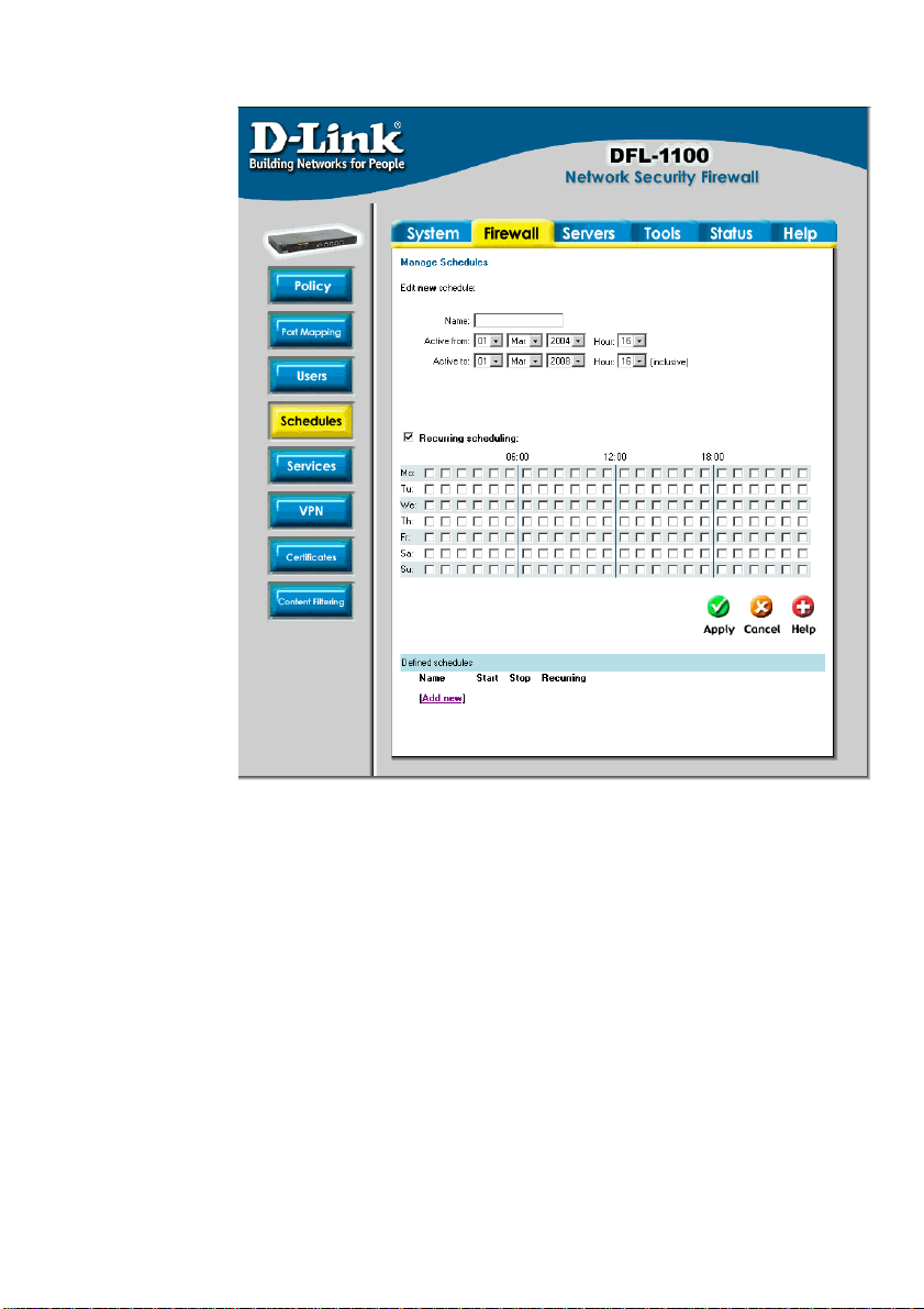
Schedules
It is possible to
configure a
schedule for
policies to take
affect. By
creating a
schedule, the
DFL-1100 is
allowing the
firewall policies
to be used at
those designated
times only. Any
activities outside
of the scheduled
time slot will not
follow the
policies and will
therefore likely
not be permitted
to pass through
the firewall. The
DFL-1100 can be
configured to
have a start time
and stop time, as
well as creating 2
different time periods in a day. For example, an organization may only want the
firewall to allow the internal network users to access the Internet during work hours.
Therefore, one may create a schedule to allow the firewall to allow traffic MondayFriday, 8AM-5PM only. During the non-work hours, the firewall will not allow Internet
access.
Add new recurring schedule
Follow these steps to add a new recurring schedule.
Step 1. Go to Firewall>Schedules and choose Add new.
Step 2. Enable the checkbox named Recurring scheduling.
Step 3. Use the checkboxes to set the times this schedule should be active.
Click Apply to apply the change, or click Cancel to discard the changes.
Page 48

Add new one-time schedule
Follow these steps to add new one-time schedule.
Step 1. Go to Firewall>Schedules, and choose Add new.
Step 2. Choose the starting and ending date, and the hour when the schedule should be
active.
Step 3. Use the checkboxes to set the times this schedule should be active inside the
specified timeframe.
Click Apply to apply the change, or click Cancel to discard the changes.
48
Page 49

Services
A service is basically a definition of a specific IP protocol with corresponding parameters. The
service http, for instance, is defined as the use of TCP protocol with a destination port 80.
Services are simplistic, in that they cannot carry out any action in the firewall on their own.
Thus, a service definition does not include any information whether the service should be
allowed through the firewall or not. That decision is made entirely by the firewall policies, in
which the service is used as a filter parameter.
Adding TCP, UDP or TCP/UDP Service
For many services, a single destination port is sufficient. The http service, for instance, uses
destination port 80. To use a single destination port, enter the port number in the destination
ports text box. In most cases, all ports (0-65535) have to be used as source ports. The
second option is to define a port range. A port range is inclusive, meaning that a range 137139 covers ports 137, 138 and 139.
Multiple ranges or individual ports may also be entered, separated by commas. For instance,
a service can be defined as having source ports 1024-65535 and destination ports 80-82, 9092, 95. In this case, a TCP or UDP packet with the destination port being one of 80, 81, 82, 90,
91, 92 or 95, and the source port being in the range 1024-65535, will match this service.
Follow these steps to add a TCP, UDP or TCP/UDP service.
Step 1. Go to Firewall>Service and choose Add New.
Step 2. Enter a Name for the service in the name field. This name will appear in the
service list when you add a new policy. The name can contain numbers (0-9) and upper
and lower case letters (A-Z, a-z), and the special characters - and _. No other special
characters and spaces are allowed.
Step 3. Select TCP/UDP Service.
Step 4. Select the protocol (either TCP, UDP or both TCP/UDP) used by the service.
Step 5. Specify a source port or range for this service by typing in the low and high port
numbers. Enter 0-65535 for all ports, or a single port like 80 for only one source port.
Step 6. Specify a destination port or range for this service by typing in the low and high
port numbers. Enter 0-65535 for all ports, or a single port like 80 for only one destination
port.
Step 7. Enable the Syn Relay checkbox if you want to protect the destination from SYN
flood attacks.
Click Apply to apply the change, or click Cancel to discard the changes.
Page 50

Adding other IP Protocols
When the desired type of service is IP Protocol, an IP protocol number may be specified in
the text field. To have the service match the GRE protocol, for example, the IP protocol
should be specified as 47. A list of some defined IP protocols can be found in the appendix
named IP Protocol Numbers.
IP protocol ranges can be used to specify multiple IP protocols for one service. An IP protocol
range is similar to the TCP and UDP port range described previously; the range 1-4, 7 will
match the protocols ICMP, IGMP, GGP, IP-in-IP and CBT.
Follow these steps to add a TCP, UDP or TCP/UDP service.
Step 1. Go to Firewall>Service and choose New.
Step 2. Enter a Name for the service in the name field. This name will appear in the
service list when you add a new policy. The name can contain numbers (0-9) and upper
and lower case letters (A-Z, a-z), and the special characters - and _. No other special
characters and spaces are allowed.
Step 3. Select IP Protocol.
Step 4. Specify a comma-separated list of IP protocols.
Click Apply to apply the change, or click Cancel to discard the changes.
Grouping Services
Services can be grouped in order to simplify configuration. Consider a web server using
standard http as well as SSL encrypted http (https). Instead of having to create two separate
rules allowing both types of services through the firewall, a service group named, for instance,
Web, can be created, with the http and the https services as group members.
Follow these steps to add a group.
Step 1. Go to Firewall> Service and choose New.
Step 2. Enter a Name for the service group in the name field. This name will appear in the
service list when you add a new policy. The name can contain numbers (0-9) and upper
and lower case letters (A-Z, a-z), and the special characters - and _. No other special
characters and spaces are allowed.
Step 3. Select Group.
Step 4. Specify a comma-separated list of existing services.
Click Apply to apply the change, or click Cancel to discard the changes.
50
Page 51

Protocol-independent settings
Allow ICMP errors from the destination to the source – ICMP error messages are sent
in several situations: for example, when an IP packet cannot reach its destination. The
purpose of these error control messages is to provide feedback about problems in the
communication environment.
However, ICMP error messages and firewalls are usually not a very good combination; the
ICMP error messages are initiated at the destination host (or a device within the path to the
destination) and sent to the originating host. The result is that the ICMP error message will be
interpreted by the firewall as a new connection and dropped, if not explicitly allowed by the
firewall rule-set. Allowing any inbound ICMP message to have those error messages
forwarded is generally not a good idea.
To solve this problem, DFL-1100 can be instructed to pass an ICMP error message only if it is
related to an existing connection. Check this option to enable this feature for connections
using this service.
ALG – Like other stateful inspection based firewalls, the DFL-1100 filters information found in
packet headers, for instance in IP, TCP, UDP and ICMP headers.
In some situations, though, filtering on header data only is not sufficient. The FTP protocol, for
instance, includes IP address and port information in the protocol payload. In these cases, the
firewall needs to be able to examine the payload data and carry out appropriate actions. DFL1100 provides this functionality using Application Layer Gateways, also known as ALGs.
To use an Application Layer Gateway, the appropriate Application Layer Gateway definition is
selected in the dropdown menu. The selected Application Layer Gateway will thus manage
network traffic that matches the policy using this service.
Currently, DFL-1100 supports two Application Layer Gateways, one is used to manage the
FTP protocol and the other one is an HTTP Content Filtering ALG. For detailed information
about how to configure the HTTP Application Layer Gateway, please see the Content Filtering
chapter.
Page 52

VPN
This chapter introduces IPSec, the method, or rather set of methods used to provide VPN
functionality. IPSec, Internet Protocol Security, is a set of protocols defined by the IETF,
Internet Engineering Task Force, to provide IP security at the network layer.
An IPSec based VPN, such as the DFL-1100 VPN, is made up of two parts:
• Internet Key Exchange protocol (IKE)
• IPSec protocols (ESP)
The first part, IKE, is the initial negotiation phase, where the two VPN endpoints agree on
which methods will be used to provide security for the underlying IP traffic. Furthermore, IKE
is used to manage connections, by defining a set of Security Associations, SAs, for each
connection. SAs are unidirectional, so there will be at least two SAs per IPSec connection.
The other part is the actual IP data being transferred, using the encryption and authentication
methods agreed upon in the IKE negotiation. This can be accomplished in a number of ways;
by using the IPSec protocol ESP.
To set up a Virtual Private Network (VPN), you do not need to configure an Access Policy to
enable encryption. Just fill in the following settings: VPN Name, Source Subnet (Local Net),
Destination Gateway (If LAN-to-LAN), Destination Subnet (If LAN-to-LAN) and Authentication
Method (Pre-shared key or Certificate). The firewalls on both ends must use the same Preshared key or set of Certificates and IPSec lifetime to make a VPN connection.
52
Page 53
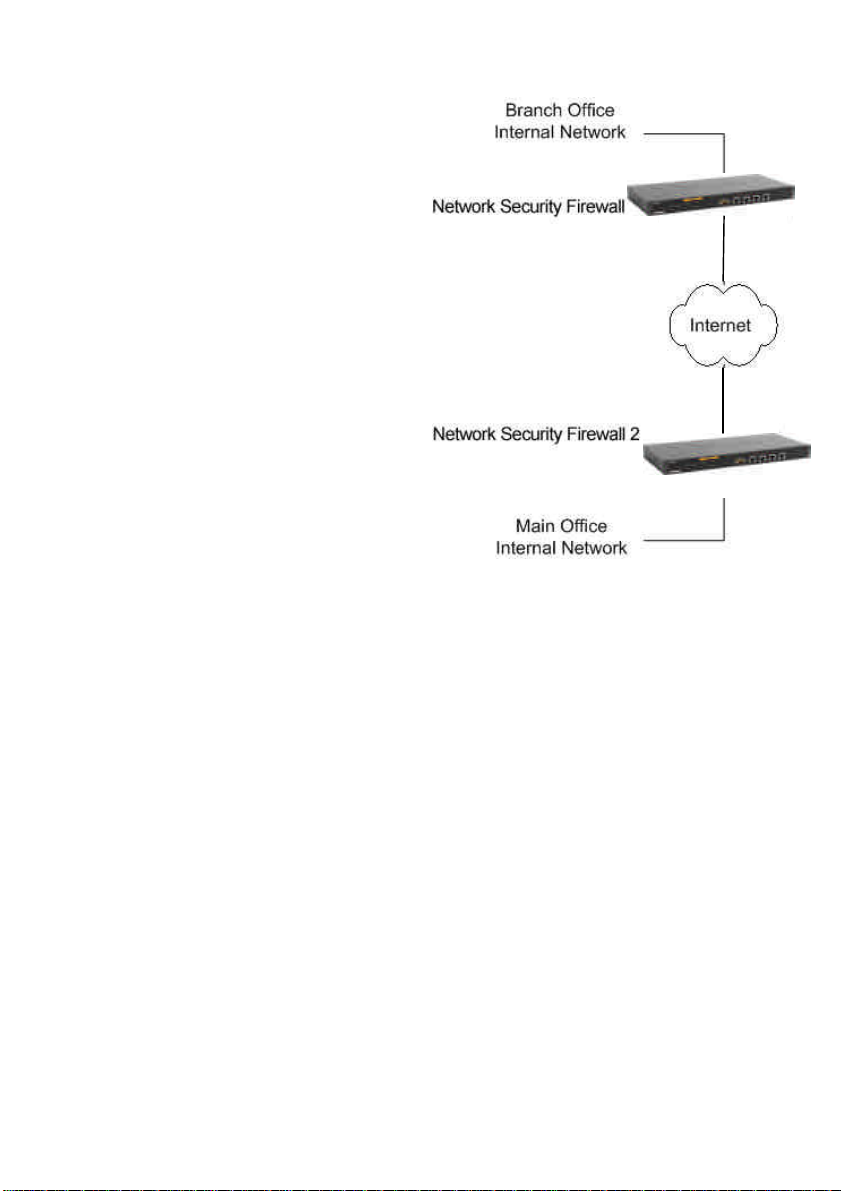
IPSec VPN between two
networks
In the following example users on the main
office internal network can connect to the
branch office internal network or vice versa.
Communication between the two networks
takes place in an encrypted VPN tunnel that
connects the two DFL-1100 Network Security
Firewalls across the Internet. Users on the
internal networks are not aware that when
they connect to a computer on the other
network that the connection runs across the
Internet.
As shown in the example, you can use the
DFL-1100 to protect a branch office and a
small main office. Both of these DFL-1100s
can be configured as IPSec VPN gateways to
create the VPN that connects the branch
office network to the main office network.
The example shows a VPN between two
internal networks, but you can also create
VPNs between an internal network behind one
VPN gateway and a DMZ network behind another, or between two DMZ networks. The
networks at the ends of the VPN tunnel are selected when you configure the VPN policy.
DFL-1100
DFL-1100
Creating a LAN-to-LAN VPN Tunnel
Follow these steps to add a LAN-to-LAN Tunnel.
Step 1. Go to Firewall>VPN and choose Add new.
Step 2. Enter a Name for the new tunnel in the name field. The name can contain
numbers (0-9) and upper and lower case letters (A-Z, a-z), and the special characters -
and _. No other special characters and spaces are allowed.
Step 3. Specify your local network, or your side of the tunnel, for example
192.168.1.0/255.255.255.0, in the Local Net field.
Step 4. Choose the authentication type, either PSK (Pre-shared Key) or Certificate-based.
If you choose PSK make sure both firewalls use exactly the same PSK.
Step 5. As Tunnel Type choose LAN-to-LAN tunnel and specify the network behind the
other DFL-1100 as Remote Net, also specify the external IP of the other DFL-1100; this
can be an IP or a DNS name.
Click the Apply button below to apply the change or click Cancel to discard changes.
Repeat this on the firewall on the other site.
Page 54
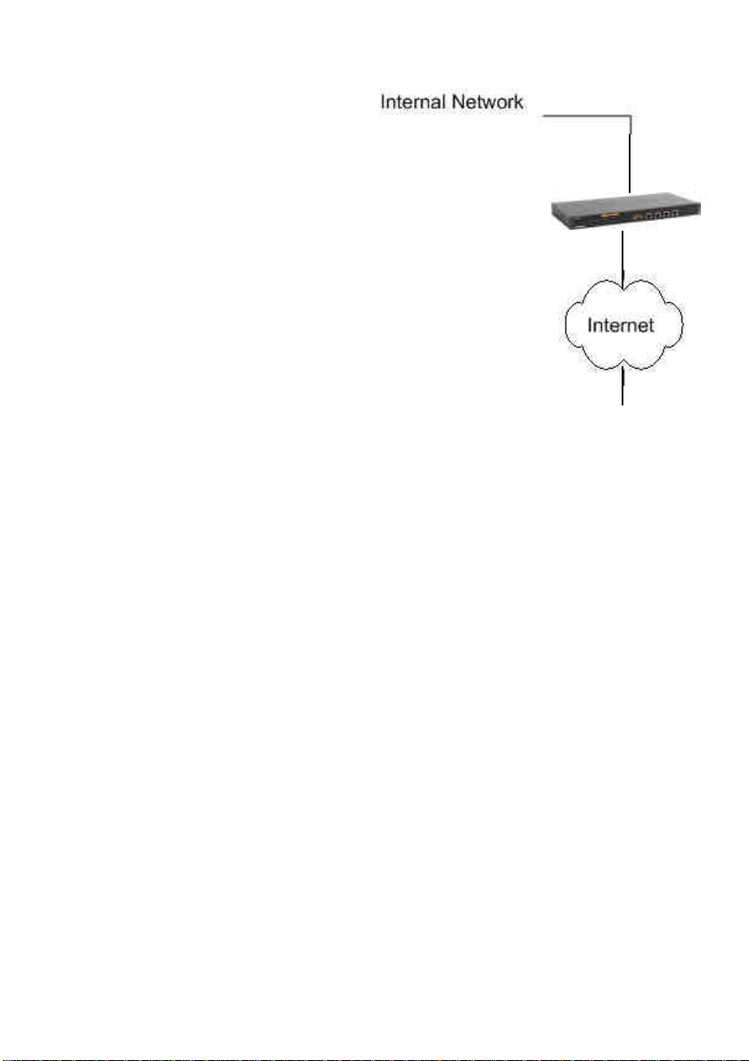
IPSec VPN between
client and an internal
network
In the following example, users can
connect to the main office internal
network from anywhere on the
Internet. Communication between
the client and the internal network
takes place in an encrypted VPN
tunnel that connects the DFL-1100
and the roaming users across the
Internet.
The example shows a VPN between
a roaming VPN client and the internal
network, but you can also create a
VPN tunnel that uses the DMZ
network. The networks at the ends of
the VPN tunnel are selected when
you configure the VPN policy.
DFL-1100 VPN Gateway
Roaming VPN Client
Creating a Roaming Users Tunnel
Follow these steps to add a roaming user’s tunnel.
Step 1. Go to Firewall >VPN and choose Add new.
Step 2. Enter a Name for the new tunnel in the name field. The name can contain
numbers (0-9) and upper and lower case letters (A-Z, a-z), and the special characters -
and _. No other special characters and spaces are allowed.
Step 3. Specify your local network, or your side of the tunnel, for example
192.168.1.0/255.255.255.0, in the Local Net field. This is the network your roaming VPN
clients should be allowed to connect to.
Step 4. Choose the authentication type, either PSK (Pre-shared Key) or Certificate-based.
If you choose PSK, make sure the clients use exactly the same PSK.
Step 5. As Tunnel Type choose Roaming User.
Click the Apply button below to apply the change or click Cancel to discard changes.
54
Page 55

VPN – Advanced Settings
Advanced settings for a VPN tunnel are used when one needs to change some
characteristics of the tunnel when, for example, trying to connect to a third party VPN
Gateway. The different settings to set per tunnel are the following:
Limit MTU
With this setting it’s possible to limit the MTU (Max Transferable Unit) of the VPN tunnel.
IKE Mode
Specify if Main mode IKE or Aggressive Mode IKE should be used when establishing
outbound VPN Tunnels. Inbound main mode connections will always be allowed. Inbound
aggressive mode connections will only be allowed if this setting is set to aggressive mode.
IKE DH Group
Here it’s possible to configure the Diffie-Hellman group to 1 (768-bit), 2 (1024-bit) or 5
(1536-bit).
PFS – Perfect Forward Secrecy
If PFS, Perfect Forwarding Secrecy, is enabled, a new Diffie-Hellman exchange is
performed for each phase-2 negotiation. While this is slower, it makes sure that no keys
are dependent on any other previously used keys; no keys are extracted from the same
initial keying material. This is to make sure that, in the unlikely event that some key was
compromised; no subsequent keys can be derived.
NAT Traversal
Here it’s possible to configure how the NAT Traversal code should behave.
Disabled - The firewall does not send the Vendor ID's that include NAT-T support when
setting up the tunnel.
On if supported and need NAT - Will only use NAT-T if one of the VPN gateways is
NATed.
On if supported - Always tries to use NAT-T when setting up the tunnel.
Keepalives
No keepalives – Keep-alive is disabled.
Automatic keepalives - The firewall will send ICMP pings to IP addresses automatically
discovered from the VPN Tunnel settings.
Manually configured IP addresses - Configure the source and destination IP addresses
used when sending the ICMP pings.
Page 56

Proposal Lists
To agree on the VPN connection parameters, a negotiation process is performed. As the
result of the negotiations, the IKE and IPSec security associations (SAs) are established.
As the name implies, a proposal is the starting point for the negotiation. A proposal defines
encryption parameters, for instance encryption algorithm, life times etc, that the VPN
gateway supports.
There are two types of proposals, IKE proposals and IPSec proposals. IKE proposals are
used during IKE Phase-1 (IKE Security Negotiation), while IPSec proposals are using
during IKE Phase-2 (IPSec Security Negotiation).
A Proposal List is used to group several proposals. During the negotiation process, the
proposals in the proposal list are offered to the remote VPN gateway one after another
until a matching proposal is found.
IKE Proposal List
Cipher – Specifies the encryption algorithm used in this IKE proposal. Supported
algorithms are AES, 3DES, DES, Blowfish, Twofish and CAST128.
Hash – Specifies the hash function used to calculate a check sum that reveals if the data
packet is altered while being transmitted. MD5 and SHA1 are supported algorithms.
Life Times – Specifies in KB or seconds when the security associations for the VPN
tunnel need to be re-negotiated.
IPSec Proposal List
Cipher – Specifies the encryption algorithm used in this IPSec proposal. Supported
algorithms are AES, 3DES, DES, Blowfish, Twofish and CAST128.
HMAC – Specifies the hash function used to calculate a check sum that reveals if the data
packet is altered while being transmitted. MD5 and SHA1 are supported algorithms.
Life Times – Specifies in KB or seconds when the security associations for the VPN
tunnel need to be re-negotiated.
56
Page 57

Certificates
A certificate is a digital proof of identity. It links an identity to a public key in a trustworthy
manner. Certificates can be used to authenticate individual users or other entities. These
types of certificates are commonly called end-entity certificates.
Before a VPN tunnel with certificate based authentication can be set up, the firewall needs
a certificate of its own and that of the remote firewall. These certificates can either be self-
signed certificates, or issued by a CA.
Trusting Certificates
When setting up a VPN tunnel, the firewall has to be told whom it should trust. When using
pre-shared keys, this is simple. The firewall trusts anyone who has the same pre-shared
key.
When using certificates, on the other hand, you tell the firewall that it can trust anyone
whose certificate is signed by a given CA. Before a certificate is accepted, the following
steps are taken to verify the validity of the certificate:
• Construct a certification path up to the trusted root CA.
• Verify the signatures of all certificates in the certification path.
• Fetch the CRL for each certificate to verify that none of the certificates have been
revoked.
Local identities
This is a list of all the local identity certificates that can be used in VPN tunnels. A local
identity certificate is used by the firewall to prove its identity to the remote VPN peer.
To add a new local identity certificate, click Add new. The following pages will allow you to
specify a name for the local identity, and upload the certificate and private key files. This
certificate can be selected in the Local Identity field on the VPN page.
This list also includes a special certificate called Admin. This is the certificate used by the
web interface to provide HTTPS access.
Note: The certificate named Admin can only be replaced, not deleted or renamed. This is
used for HTTPS access to the DFL-1100.
Certificates of remote peers
This is a list of all certificates of individual remote peers.
To add a new remote peer certificate, click Add new. The following pages will allow you to
specify a name for the remote peer certificate and upload the certificate file. This
certificate can be selected in the Certificates field on the VPN page.
Certificate Authorities (CA)
This is a list of all CA certificates. To add a new Certificate Authority certificate, click Add
new. The following pages will allow you to specify a name for the CA certificate and
Page 58

upload the certificate file. This certificate can be selected in the Certificates field on the
VPN page.
Note: If the uploaded certificate is a CA certificate, it will automatically be placed in the
Certificate Authorities list, even if Add New was clicked in the Remote Peers list. Similiarly,
a non-CA certificate will be placed in the Remote Peers list even if Add New was clicked
from the Certificate Authorities list.
Identities
This is a list of all the configured Identity lists. An Identity list can be used on the VPN
page to limit inbound VPN access from this list of known identities.
Normally, a VPN tunnel is established if the certificate of the remote peer is present in the
Certificates field in the VPN section, or if the remote peer's certificate is signed by a CA
whose certificate is present in the Certificates field in the VPN section. However, in some
cases it might be necessary to limit who can establish a VPN tunnel even among peers
signed by the same CA.
The Identity list can be selected in the Identity List field on the VPN page.
If an Identity List is configured, the firewall will match the identity of the connecting remote
peer against the Identity List, and only allow it to open the VPN tunnel if it matches the
contents of the list.
If no Identity List is used, no identity matching is done.
58
Page 59
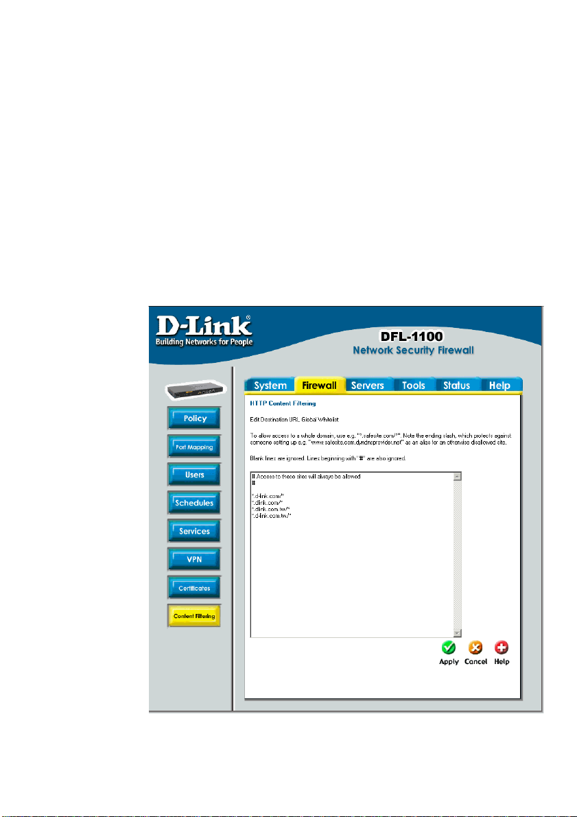
Content Filtering
DFL-1100 HTTP content filtering can be configured to scan all HTTP content protocol
streams for URLs or for Web page content. If a requested URL is on the URL block list,
the DFL-1100 will block that Web page.
You can configure URL blacklist to block all or just some of the pages on a website. Using
this feature you can deny access to parts of a web site without denying access to it
completely.
The HTTP content filtering can also be configured to strip contents like ActiveX, Flash and
cookies.
There is also a URL whitelist for URLs that should be excluded from all Content Filtering.
Note: For HTTP URL filtering to work, all HTTP traffic needs to go through a policy using a
service with the HTTP ALG.
Edit the URL Global Whitelist
Follow these steps
to add or remove a
URL.
Step 1. Go to
Firewall and
Content
Filtering and
choose Edit
global URL
whitelist.
Step 2.
Add/edit or
remove the
URL that
should never
be checked
with the
Content
Filtering.
Click the Apply
button below to
apply the
change or click
Cancel to
discard
changes.
Page 60
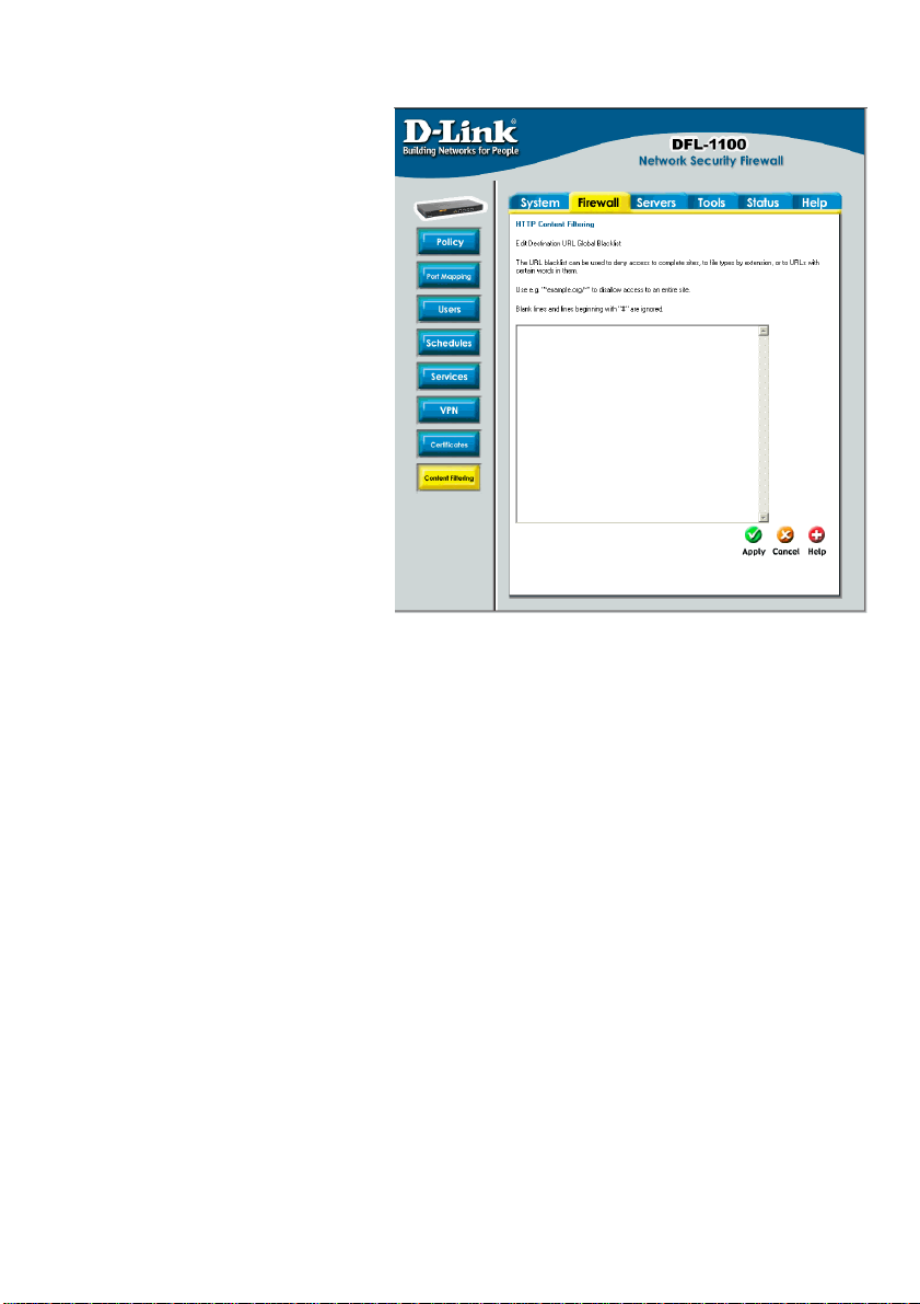
Edit the URL Global
Blacklist
Follow these steps to add or remove
a URL.
Step 1. Go to Firewall and
Content Filtering and choose Edit
global URL blacklist
Step 2. Add/edit or remove the
URL that should be checked with
the Content Filtering.
Click the Apply button below to
apply the change or click Cancel
to discard changes.
Note: For HTTP URL filtering to
work, all HTTP traffic needs to go
through a policy using a service
with the HTTP ALG.
60
Page 61

Active content handling
Active content handling can be enabled or disabled by checking the checkbox before each
type you would like to strip. For example, to strip ActiveX and Flash, enable the checkbox
named Strip ActiveX objects. It’s possible to strip ActiveX, Flash, Java, JavaScript and
VBScript. It’s also possible to block cookies.
Note: For HTTP URL filtering to work, all HTTP traffic needs to go through a policy using a
service with the HTTP ALG.
Page 62
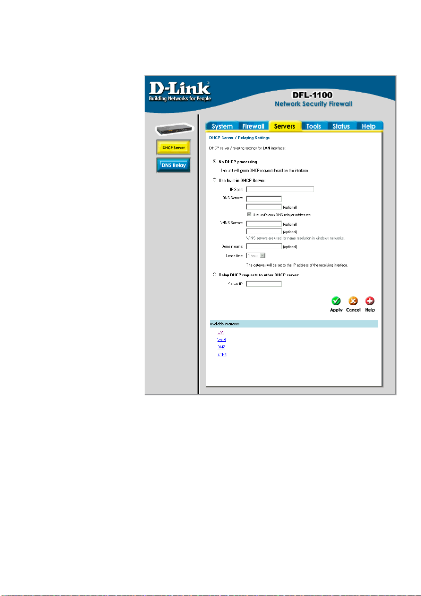
Servers
DHCP Server
Settings
The DFL-1100 contains a
DHCP server; DHCP
(Dynamic Host
Configuration Protocol) is a
protocol that lets network
administrators automatically
assign IP numbers to
computers on a network.
The DFL-1100 DHCP
Server helps to minimize
the work necessary to
administer a network, as
there is no need for another
server running DHCP
Server software.
The DFL-1100 DHCP
Server only implements a
subset of the DHCP
protocol necessary to serve
a small network, these are:
• IP address
• Netmask
• Subnet
• Gateway address
• DNS Servers
• WINS Servers
• Domain name
The DFL-1100 DHCP Server assigns and manages IP addresses from specified address
pools within the firewall to the DHCP clients.
Note: Leases are remembered over a re-configure or reboot of the firewall.
The DFL-1100 also includes a DHCP Relayer. A DHCP relayer is a form of gateway between
a DHCP Server and its users. The relayer intercepts DHCP queries from the users and
forwards them to a DHCP server, while setting up dynamic routes based on leases. This
enables the firewall to keep an accurate routing table based on active users and protects the
DHCP server to some degree.
Note: There can only be one DHCP Server or DHCP Relay configured per interface.
62
Page 63

Enable DHCP Server
To enable the DHCP Server on an interface, click on Servers in the menu bar, and then click
DHCP Server below it.
Follow these steps to enable the DHCP Server on the LAN interface.
Step 1. Choose the LAN interface from the Available interfaces list.
Step 2. Enable by checking the Use built-in DHCP Server box.
Step 3. Fill in the IP Span, the start and end IP for the range of IP addresses that the DFL-
1100 can assign.
Step 4. Enter the DNS servers that the DHCP server will assign to the clients, at least one
should be provided. If the DNS relayer is configured, the DHCP server can assign those.
Step 5. Optionally, type in the WINS servers that the DHCP server will assign to the
clients.
Step 6. Optionally type in the domain that the DHCP server assigns to the clients.
Step 7. Choose the time period during which the DHCP server will give out leases before
the client will have to renew them.
Click the Apply button below to apply the setting or click Cancel to discard changes
Enable DHCP Relay
To enable the DHCP Relay on an interface, click on Servers in the menu bar, and then
click DHCP Server below it.
Follow these steps to enable the DHCP Relayer on the LAN interface.
Step 1. Choose the LAN interface from the Available interfaces list.
Step 2. Enable by checking the Relay DHCP Requests to other DHCP server box.
Step 3. Fill in the IP address of the DHCP Server (note that it should be on another
interface then where the DHCP request is coming from), i.e., a server on the DMZ.
Click the Apply button below to apply the setting or click Cancel to discard changes
Disable DHCP Server/Relayer
To disable the DHCP Server on an interface, click on Servers in the menu bar, and then click
DHCP Server below it. Here click on the interface in which you wish to disable the DHCP
server or relayer.
Follow these steps to disable the DHCP Server or Relayer on the LAN interface.
Step 1. Choose the LAN interface from the Available interfaces list.
Step 2. Disable by checking the No DHCP processing box.
Click the Apply button below to apply the setting or click Cancel to discard changes
Page 64
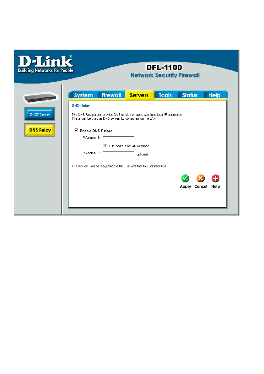
DNS Relayer Settings
Click on Servers in the menu bar, and then click DNS Relay below it. The DFL-1100
contains a DNS relayer that can be configured to relay DNS queries from the internal LAN to
the DNS servers used by the firewall itself.
Enable DNS Relayer
Follow these steps to enable the DNS Relayer.
Step 1. Enable by checking the Enable DNS Relayer box.
Step 2. Enter the IP numbers that the DFL-1100 should listen for DNS queries on.
Note: If Use address of LAN interface is checked, you don’t have to enter an IP in IP
Address 1 as the firewall will know what address to use.
Click the Apply button below to apply the setting or click Cancel to discard changes.
64
Page 65

Disable DNS Relayer
Follow these steps to disable the DNS Relayer.
Step 1. Disable by un-checking the Enable DNS Relayer box.
Click the Apply button below to apply the setting or click Cancel to discard changes.
Page 66
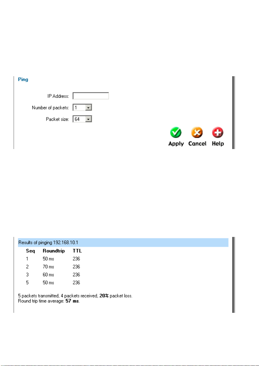
Tools
Ping
Click on Tools in the menu bar, and then click Ping below it. This tool is used to send a
specified number of ICMP Echo Request packets to a given destination. All packets are sent
in immediate succession rather than one per second. This behavior is the best one suited for
diagnosing connectivity problems.
• IP Address – Target IP to send the ICMP Echo Requests to.
• Number of packets – Number of ICMP Echo Request packets to send, up to 10.
• Packet size – Size of the packet to send, between 32 and 1500 bytes.
Ping Example
In this example, the IP Address is 192.168.10.1, and the Number of packets is five. After
clicking on Apply the firewall will start to send the ICMP Echo Requests to the specified IP.
After a few seconds the result will be shown. In this example only four out of five packets were
received back, a 20% packet loss, and the average time for the packets to travel to and from
the specified IP was 57 ms.
66
Page 67

Dynamic DNS
The Dynamic DNS (requires Dynamic DNS Service) allows you to alias a dynamic IP
address to a static hostname, allowing your device to be more easily accessed by specific
name. When this function is enabled, the IP address in Dynamic DNS Server will be
automatically updated with the new IP address provided by the ISP.
Click DynDNS in the Tools menu to enter Dynamic DNS configuration.
The firewall provides a list of a few predefined DynDNS service providers; users have to
register with one of these providers before using this function.
Add Dynamic DNS Settings
Follow these steps to enable Dynamic DNS.
Step 1. Go to Tools and DynDNS.
Step 2. Choose the Dynamic DNS service you would like to use, and fill in the needed
information, username and password in all cases and domains except cjb.net.
Click the Apply button below to apply the setting or click Cancel to discard changes.
Page 68
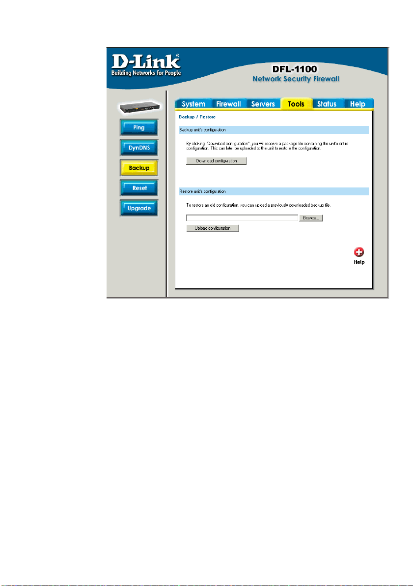
Backup
Click on Tools in
the menu bar, and
then click Backup
below it. Here a
administrator can
backup and restore
the configuration.
The configuration
file stores system
settings, IP
addresses of
Firewall’s network
interfaces, address
table, service table,
IPSec settings,
port mapping and
policies. When the
configuration
process is
completed, the
system
administrator can
download the
configuration file
into the local disc
as a backup. System Administrators can restore the firewall’s configuration file with the one
stored on the hard drive.
Exporting the DFL-1100’s Configuration
Follow these steps to export the configuration.
Step 1. Under the Tools menu and the Backup section, click on the Download
configuration button.
Step 2. When the File Download pop-up window appears, choose the destination place in
which to save the exported file. The Administrator may choose to rename the file if
preferred.
Restoring the DFL-1100’s Configuration
Follow these steps to restore the configuration.
Step 1. Under the Tools menu and the Backup section, click on the Browse button next
to the empty field. When the Choose File pop-up window appears, select the file that
contains the saved firewall settings, then click OK.
Step 2. Click Upload Configuration to import the file into the Firewall.
68
Page 69
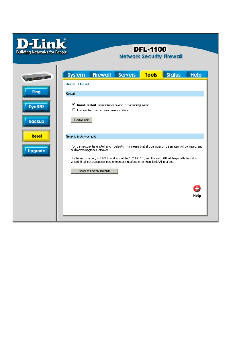
Restart/Reset
Restarting the DFL-1100
Follow these steps to restart the DFL-1100.
Step 1. Choose if you want to do a quick or full restart.
Step 2. Click Restart Unit and the unit will restart.
Restoring system settings to factory defaults
Use the following procedure to restore system settings to the values set at the factory. This
procedure may change the DFL-1100 firmware version to a lower version (if it has been
upgraded).
This procedure deletes all of the changes that you have made to the DFL-1100 configuration
and reverts the system to its original configuration including resetting interface addresses.
Page 70

Follow these steps to reset the DFL-1100 to factory default.
Step 1. Under the Tools menu and the Reset section, click on the Reset to Factory
Defaults button.
Step 2. Click OK in the dialog to reset the unit to factory default, or press Cancel to cancel.
You can restore your system settings by uploading a previously downloaded system
configurations file to the DFL-1100 if a backup of the device has been done.
70
Page 71
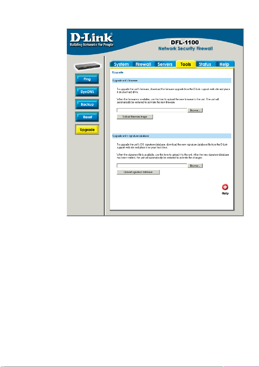
Upgrade
The DFL-1100’s
software, IDS
signatures and
system parameters
are all stored on a
flash memory card.
The flash memory
card is re-writable
and re-readable.
Upgrade
Firmware
To upgrade the
firmware first
download the
correct firmware
from D-Link. After
having the newest
version of software,
please store it on
the hard disk, then
connect to the
firewall’s
configuration utility,
enter Upgrade on
the Tools menu,
click Browse and
choose the file
name of the newest version of the firmware, then click Upload firmware image.
The updating process won’t overwrite the system configuration, so it is not necessary but still
a good idea to backup before upgrading the software.
Upgrade IDS Signature-database
To upgrade the signature-database first download the newest IDS signatures from D-Link.
After having the newest version of software connect to the firewall’s configuration utility, enter
Upgrade on the Tools menu, click Browse in the Upgrade Unit’s signature-database
section and choose the file name of the newest version of the IDS signatures, then click
Upload signature database.
Page 72
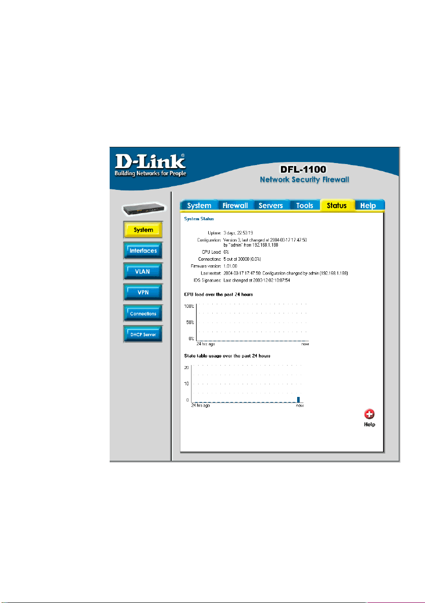
Status
In this section, the DFL-1100 displays the status information about the Firewall.
The Administrator may use Status to check the System Status, Interface statistics, VPN,
connections and DHCP Servers.
System
Click on Status in the menu bar, and then click System below it. A window will appear
providing
information about
the DFL-1100.
Uptime – The time
the firewall has
been running,
since the last
reboot or start.
CPU Load –
Percentage of
CPU used.
Connections –
Number of current
connections
through the firewall.
Firmware
version – The
firmware version
running on the
firewall.
Last restart – The
reason for the last
restart.
IDS Signatures –
The IDS signature
versions.
There are also two
graphs on this
page, one showing the CPU usage during the last 24 hours. The other one is showing the
state table usage during the last 24 hours.
72
Page 73
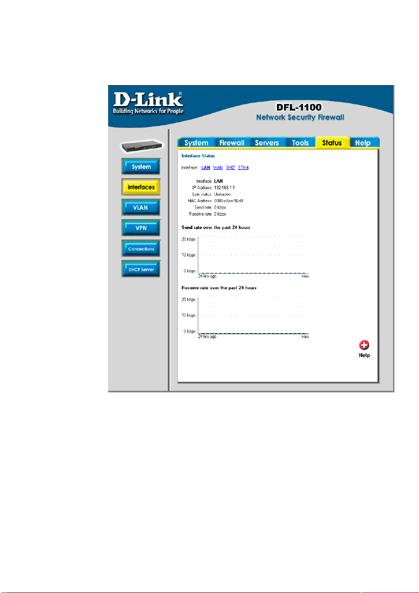
Interfaces
Click on Status in the menu bar, and then click Interfaces below it. A window will appear
providing information about the interfaces in the DFL-1100. By default information about the
LAN interface will be show, to see another one click on that interface (WAN or DMZ).
Interface – Name
of the interface
shown, LAN, WAN
or DMZ.
IP Address – IP
address of the
interface.
Link status –
Displays what link
the current
interface has, the
speed can be 10 or
100 Mbps and the
duplex can be Half
or Full.
MAC Address –
MAC address of
the interface.
Send rate –
Current amount of
traffic sent trough
the interface.
Receive rate –
Current amount of
traffic received
trough the
interface.
There are also two graphs displaying the send and receive rate trough the interfaces during
the last 24 hours.
Page 74
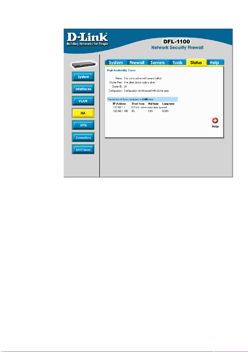
HA
Click on Status in
the menu bar, and
then click HA
below it. A window
will appear
providing
information about
the HA Cluster
configured in the
DFL-1100.
Status - Status of
the cluster, will
show if the unit is
active or inactive.
Cluster Peer Status of the other
unit in the cluster.
Cluster ID - ID
used for this
cluster
Configuration –
Status of the
configuration
synchronization, if both peers are using the same configuration or if it’s in the process of being
synchronized.
74
Page 75
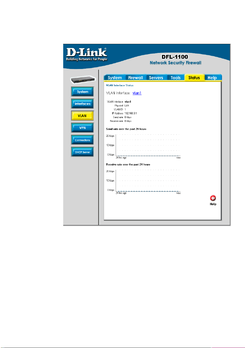
VLAN
Click on Status in the menu bar, and then click VLAN below it. A window will appear
providing information about the virtual interfaces configured in the DFL-1100.
VLAN Interface –
Name of the virtual
interface shown.
VLAN ID – ID
assigned to the
VLAN.
IP Address – IP
address of the
virtual interface.
Send rate –
Current amount of
traffic sent through
the interface.
Receive rate –
Current amount of
traffic received
through the
interface.
There are two
graphs displaying
the send and
receive rate
through the
interfaces during
the last 24 hours.
Page 76
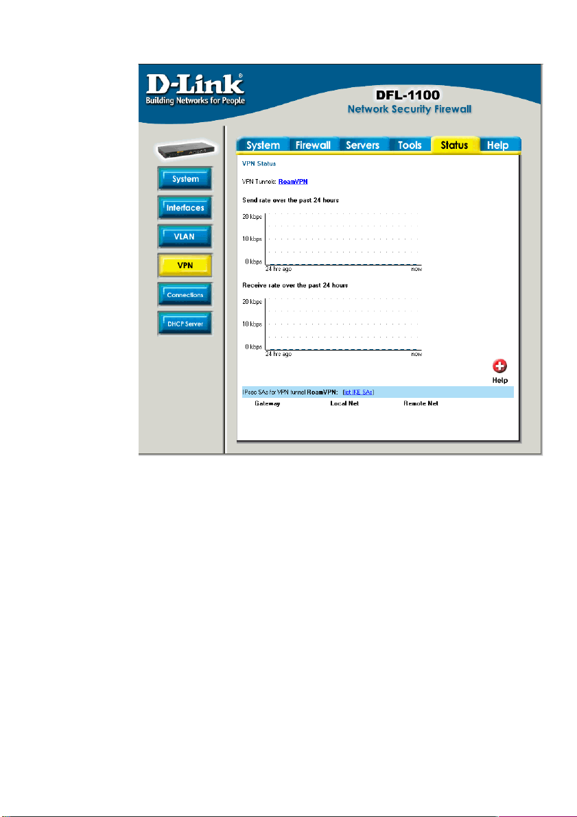
VPN
Click on Status
in the menu bar,
and then click
Interfaces below
it. A window will
appear providing
information about
the VPN
connections in
the DFL-1100.
By default,
information about
the first VPN
tunnel will be
shown. Click on
that VPN tunnel’s
name to view it.
The two graphs
display the send
and receive rate
through the
selected VPN
tunnel during the
last 24 hours.
In this example a
tunnel named
Roaming VPN is
selected, this is a tunnel that allows roaming users. So under the IPSec SA listing each
roaming user connected to this tunnel is shown.
76
Page 77
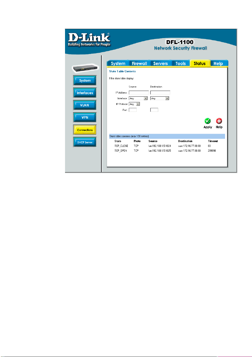
Connections
Click on Status in
the menu bar, and
then click
Connections
below it. A window
will appear
providing
information about
the content of the
state table.
Shown are the last
100 connections
opened through
the firewall.
Connections are
created when
traffic is permitted
to pass via the
policies.
Each connection
has two timeout
values, one in
each direction.
These are updated when the firewall receives packets from each end of the connection. The
value shown in the Timeout column is the lower of the two values.
Possible values in the State column include: TPC_CLOSE, TCP_OPEN, SYN_RECV,
FIN_RECV and so on.
The Proto column can have:
TCP - The connection is a TCP connection
PING - The connection is an ICMP ECHO connection
UDP - The connection is a UDP connection
RAWIP - The connection uses an IP protocol other than TCP, UDP or ICMP
The Source and Destination columns shows the IP and Port interfaces of the source and
destination.
Page 78
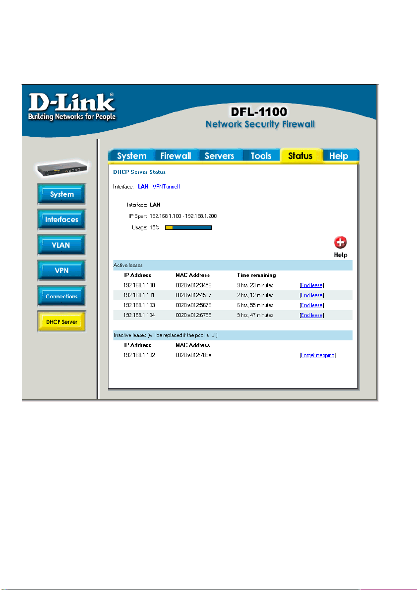
DHCP Server
Click on Status in the menu bar, and then click DHCP Server below it. A window will appear
providing information about the configured DHCP Servers. By default, information about the
LAN interface will be shown. To view another one, click on that interface.
Interface – Name of the interface the DHCP Server is running on.
IP Span – Displays the configured ranges of IP’s that are given out as DHCP leases.
Usage – Displays how much of the IP range is given out to DHCP clients.
Active leases are the current computers using this DHCP server. It is also possible to end
a computer’s lease from here, by clicking on End lease after that IP.
Inactive leases are leases that are not currently in use but have previously been used by a
computer. Computers will get their previous lease time, the next time they are on the network.
If there is no free IP in the pool when a different computer is on the network, these IP’s will be
used for new computers.
78
Page 79

How to read the logs
Although the exact format of each log entry depends on how your syslog recipient works,
most are very much alike. The way in which logs are read is also dependent on how your
syslog recipient works. Syslog daemons on UNIX servers usually log to text files, line by line.
Most syslog recipients preface each log entry with a timestamp and the IP address of the
machine that sent the log data:
Oct 20 2003 09:45:23 gateway
This is followed by the text the sender has chosen to send. All log entries from DFL-1100 are
prefaced with "EFW:" and a category, e.g. "DROP:"
Oct 20 2003 09:45:23 gateway EFW: DROP:
Subsequent text is dependent on the event that has occurred.
USAGE events
These events are sent periodically and provide statistical information regarding connections
and amount of traffic.
Example:
Oct 20 2003 09:45:23 gateway EFW: USAGE: conns=1174 if0=core ip0=127.0.0.1
tp0=0.00 if1=wan ip1=192.168.10.2 tp1=11.93 if2=lan ip2=192.168.0.1 tp2=13.27 if3=dmz
ip3=192.168.1.1 tp3=0.99
The value after conns is the number of open connections through the firewall when the usage
log was sent. The value after tp is the throughput through the firewall at the time the usage log
was logged.
DROP events
These events may be generated by a number of different functions in the firewall. The most
common source is probably the policies.
Example:
Oct 20 2003 09:42:25 gateway EFW: DROP: prio=1 rule=Rule_1 action=drop recvif=wan
srcip=192.168.10.2 destip=192.168.0.1 ipproto=TCP ipdatalen=28 srcport=3572
destport=135 tcphdrlen=28 syn=1
In this line, traffic from 192.168.10.2 coming from the WAN side of the firewall, connecting to
192.168.10.1 on port 135 is dropped. The protocol used is TCP.
CONN events
These events are generated if auditing has been enabled.
One event will be generated when a connection is established. This event will include
information about protocol, receiving interface, source IP address, source port, destination
interface, destination IP address and destination port.
Open Example:
Page 80

Oct 20 2003 09:47:56 gateway EFW: CONN: prio=1 rule=Rule_8 conn=open
connipproto=TCP connrecvif=lan connsrcip=192.168.0.10 connsrcport=3179
conndestif=wan conndestip=64.7.210.132 conndestport=80
In this line, traffic from 192.168.0.10 on the LAN interface is connecting to 64.7.210.132 on
port 80 on the WAN side of the firewall (internet).
Another event is generated when the connection is closed. The information included in the
event is the same as in the event sent when the connection was opened, with the exception
that statistics regarding sent and received traffic is also included.
Close Example:
Oct 20 2003 09:48:05 gateway EFW: CONN: prio=1 rule=Rule_8 conn=close
connipproto=TCP connrecvif=lan connsrcip=192.168.0.10 connsrcport=3179
conndestif=wan conndestip=64.7.210.132 conndestport=80 origsent=62 termsent=60
In this line, the connection in the other example is closed.
80
Page 81

Appendixes
Destination Network is
Appendix A: ICMP Types and Codes
The Internet Control Message Protocol (ICMP) has many messages that are identified by
a “type” field; many of these ICMP types have a "code" field. Here we list the types with their
assigned code fields.
Type Name Code Description Reference
0 Echo Reply 0 No Code RFC792
3 Destination Unreachable 0 Net Unreachable RFC792
1 Host Unreachable RFC792
2 Protocol Unreachable RFC792
3 Port Unreachable RFC792
4 Fragmentation Needed and
Don't Fragment was Set
5 Source Route Failed RFC792
6 Destination Network Unknown RFC792
7 Destination Host Unknown RFC792
8 Source Host Isolated RFC792
9 Communication with
Administratively Prohibited
10 Communication with
Destination Host is
Administratively Prohibited
11 Destination Network
Unreachable for Type of
Service
12 Destination Host Unreachable
for Type of Service
13 Communication
Administratively Prohibited
14 Host Precedence Violation RFC1812
15 Precedence cutoff in effect RFC1812
4 Source Quench 0 No Code RFC792
5 Redirect 0 Redirect Datagram for the
Network (or subnet)
RFC792
RFC792
RFC792
RFC792
RFC792
RFC1812
RFC792
Page 82

1 Redirect Datagram for the
Timestamp
Traceroute
Host
2 Redirect Datagram for the
Type of Service and Network
3 Redirect Datagram for the
Type of Service and Host
8 Echo 0 No Code RFC792
9 Router Advertisement 0 Normal router advertisement RFC1256
16 Does not route common traffic RFC2002
10 Router Selection 0 No Code RFC1256
11 Time Exceeded 0 Time to Live exceeded in
Transit
1 Fragment Reassembly Time
Exceeded
12 Parameter Problem 0 Pointer indicates the error RFC792
1 Missing a Required Option RFC1108
2 Bad Length RFC792
13
14 Timestamp Reply 0 No Code RFC792
15 Information Request 0 No Code RFC792
16 Information Reply 0 No Code RFC792
17 Address Mask Request 0 No Code RFC950
18 Address Mask Reply 0 No Code RFC950
30
31 Datagram Conversion
Error
40 Photuris RFC2521
0 Bad SPI RFC2521
1 Authentication Failed RFC2521
2 Decompression Failed RFC2521
3 Decryption Failed RFC2521
4 Need Authentication RFC2521
5 Need Authorization RFC2521
Source: http://www.iana.org/assignments/icmp-parameters
0 No Code RFC792
RFC1393
RFC1475
RFC792
RFC792
RFC792
RFC792
RFC792
82
Page 83

Appendix B: Common IP Protocol Numbers
These are some of the more common IP Protocols, for all follow the link after the table.
Decimal Keyword Description Reference
1 ICMP Internet Control Message RFC792
2 IGMP Internet Group Management RFC1112
3 GGP Gateway-to-Gateway
4 IP IP in IP (encapsulation) RFC2003
5 ST Stream RFC1190, RFC1819
6 TCP Transmission Control RFC793
8 EGP Exterior Gateway Protocol RFC888
17 UDP User Datagram RFC768
47 GRE General Routing
Encapsulation
50 ESP Encapsulation Security
Payload
51 AH Authentication Header RFC2402
108 IPComp I IP Payload Compression
Protocol
112 VRRP Virtual Router Redundancy
Protocol
115 L2TP Layer Two Tunneling Protocol
Source: http://www.iana.org/assignments/protocol-numbers
RFC823
RFC2406
RFC2393
Page 84

Limited Warranty
Subject to the terms and conditions set forth herein, D-Link Systems, Inc. (“D-Link”) provides this
Limited warranty for its product only to the person or entity that originally purchased the product from:
• D-Link or its authorized reseller or distributor and
• Products purchased and delivered within the fifty states of the United States, the District of Columbia,
U.S. Possessions or Protectorates, U.S. Military Installations, addresses with an APO or FPO.
Limited Warranty: D-Link warrants that the hardware portion of the D-Link products described below
will be free from material defects in workmanship and materials from the date of original retail purchase of
the product, for the period set forth below applicable to the product type (“Warranty Period”), except as
otherwise stated herein.
1-Year Limited Warranty for the Product(s) is defined as follows:
• Hardware (excluding power supplies and fans) One (1) Year
• Power Supplies and Fans One (1) Year
• Spare parts and spare kits Ninety (90) days
D-Link’s sole obligation shall be to repair or replace the defective Hardware during the Warranty
Period at no charge to the original owner or to refund at D-Link’s sole discretion. Such repair or
replacement will be rendered by D-Link at an Authorized D-Link Service Office. The replacement
Hardware need not be new or have an identical make, model or part. D-Link may in its sole discretion
replace the defective Hardware (or any part thereof) with any reconditioned product that D-Link
reasonably determines is substantially equivalent (or superior) in all material respects to the defective
Hardware. Repaired or replacement Hardware will be warranted for the remainder of the original
Warranty Period from the date of original retail purchase. If a material defect is incapable of correction, or
if D-Link determines in its sole discretion that it is not practical to repair or replace the defective Hardware,
the price paid by the original purchaser for the defective Hardware will be refunded by D-Link upon return
to D-Link of the defective Hardware. All Hardware (or part thereof) that is replaced by D-Link, or for which
the purchase price is refunded, shall become the property of D-Link upon replacement or refund.
Limited Software Warranty: D-Link warrants that the software portion of the product (“Software”)
will substantially conform to D-Link’s then current functional specifications for the Software, as set forth in
the applicable documentation, from the date of original retail purchase of the Software for a period of
ninety (90) days (“Warranty Period”), provided that the Software is properly installed on approved
hardware and operated as contemplated in its documentation. D-Link further warrants that, during the
Warranty Period, the magnetic media on which D-Link delivers the Software will be free of physical
defects. D-Link’s sole obligation shall be to replace the non-conforming Software (or defective media)
with software that substantially conforms to D-Link’s functional specifications for the Software or to refund
at D-Link’s sole discretion. Except as otherwise agreed by D-Link in writing, the replacement Software is
provided only to the original licensee, and is subject to the terms and conditions of the license granted by
D-Link for the Software. Software will be warranted for the remainder of the original Warranty Period from
the date or original retail purchase. If a material non-conformance is incapable of correction, or if D-Link
determines in its sole discretion that it is not practical to replace the non-conforming Software, the price
paid by the original licensee for the non-conforming Software will be refunded by D-Link; provided that the
non-conforming Software (and all copies thereof) is first returned to D-Link. The license granted
respecting any Software for which a refund is given automatically terminates.
Non-Applicability of Warranty: The Limited Warranty provided hereunder for hardware and
software of D-Link's products will not be applied to and does not cover any refurbished product and any
product purchased through the inventory clearance or liquidation sale or other sales in which D-Link, the
84
Page 85

sellers, or the liquidators expressly disclaim their warranty obligation pertaining to the product and in that
case, the product is being sold "As-Is" without any warranty whatsoever including, without limitation, the
Limited Warranty as described herein, notwithstanding anything stated herein to the contrary.
Submitting A Claim: The customer shall return the product to the original purchase point based on
its return policy. In case the return policy period has expired and the product is within warranty, the
customer shall submit a claim to D-Link as outlined below:
• The customer must submit with the product as part of the claim a written description of the Hardware
defect or Software nonconformance in sufficient detail to allow D-Link to confirm the same.
• The original product owner must obtain a Return Material Authorization (“RMA”) number from the
Authorized D-Link Service Office and, if requested, provide written proof of purchase of the product
(such as a copy of the dated purchase invoice for the product) before the warranty service is
provided.
• After an RMA number is issued, the defective product must be packaged securely in the original or
other suitable shipping package to ensure that it will not be damaged in transit, and the RMA number
must be prominently marked on the outside of the package. Do not include any manuals or
accessories in the shipping package. D-Link will only replace the defective portion of the Product
and will not ship back any accessories.
• The customer is responsible for all in-bound shipping charges to D-Link. No Cash on Delivery
(“COD”) is allowed. Products sent COD will either be rejected by D-Link or become the property of
D-Link. Products shall be fully insured by the customer and shipped to D-Link Systems, Inc., 17595
Mt. Herrmann, Fountain Valley, CA 92708. D-Link will not be held responsible for any packages
that are lost in transit to D-Link. The repaired or replaced packages will be shipped to the customer
via UPS Ground or any common carrier selected by D-Link, with shipping charges prepaid.
Expedited shipping is available if shipping charges are prepaid by the customer and upon request.
D-Link may reject or return any product that is not packaged and shipped in strict compliance with the
foregoing requirements, or for which an RMA number is not visible from the outside of the package. The
product owner agrees to pay D-Link’s reasonable handling and return shipping charges for any product
that is not packaged and shipped in accordance with the foregoing requirements, or that is determined by
D-Link not to be defective or non-conforming.
What Is Not Covered: This limited warranty provided by D-Link does not cover: Products, if in DLink’s judgment, have been subjected to abuse, accident, alteration, modification, tampering, negligence,
misuse, faulty installation, lack of reasonable care, repair or service in any way that is not contemplated in
the documentation for the product, or if the model or serial number has been altered, tampered with,
defaced or removed; Initial installation, installation and removal of the product for repair, and shipping
costs; Operational adjustments covered in the operating manual for the product, and normal maintenance;
Damage that occurs in shipment, due to act of God, failures due to power surge, and cosmetic damage;
Any hardware, software, firmware or other products or services provided by anyone other than D-Link;
Products that have been purchased from inventory clearance or liquidation sales or other sales in which
D-Link, the sellers, or the liquidators expressly disclaim their warranty obligation pertaining to the product.
Repair by anyone other than D-Link or an Authorized D-Link Service Office will void this Warranty.
Disclaimer of Other Warranties: EXCEPT FOR THE LIMITED WARRANTY SPECIFIED HEREIN,
THE PRODUCT IS PROVIDED “AS-IS” WITHOUT ANY WARRANTY OF ANY KIND WHATSOEVER
INCLUDING, WITHOUT LIMITATION, ANY WARRANTY OF MERCHANTABILITY, FITNESS FOR A
PARTICULAR PURPOSE AND NON-INFRINGEMENT. IF ANY IMPLIED WARRANTY CANNOT BE
DISCLAIMED IN ANY TERRITORY WHERE A PRODUCT IS SOLD, THE DURATION OF SUCH
IMPLIED WARRANTY SHALL BE LIMITED TO NINETY (90) DAYS. EXCEPT AS EXPRESSLY
COVERED UNDER THE LIMITED WARRANTY PROVIDED HEREIN, THE ENTIRE RISK AS TO THE
QUALITY, SELECTION AND PERFORMANCE OF THE PRODUCT IS WITH THE PURCHASER OF
THE PRODUCT.
Page 86
Limitation of Liability: TO THE MAXIMUM EXTENT PERMITTED BY LAW, D-LINK IS NOT LIABLE
UNDER ANY CONTRACT, NEGLIGENCE, STRICT LIABILITY OR OTHER LEGAL OR EQUITABLE
THEORY FOR ANY LOSS OF USE OF THE PRODUCT, INCONVENIENCE OR DAMAGES OF ANY
CHARACTER, WHETHER DIRECT, SPECIAL, INCIDENTAL OR CONSEQUENTIAL (INCLUDING, BUT
NOT LIMITED TO, DAMAGES FOR LOSS OF GOODWILL, LOSS OF REVENUE OR PROFIT, WORK
STOPPAGE, COMPUTER FAILURE OR MALFUNCTION, FAILURE OF OTHER EQUIPMENT OR
COMPUTER PROGRAMS TO WHICH D-LINK’S PRODUCT IS CONNECTED WITH, LOSS OF
INFORMATION OR DATA CONTAINED IN, STORED ON, OR INTEGRATED WITH ANY PRODUCT
RETURNED TO D-LINK FOR WARRANTY SERVICE) RESULTING FROM THE USE OF THE
PRODUCT, RELATING TO WARRANTY SERVICE, OR ARISING OUT OF ANY BREACH OF THIS
LIMITED WARRANTY, EVEN IF D-LINK HAS BEEN ADVISED OF THE POSSIBILITY OF SUCH
DAMAGES. THE SOLE REMEDY FOR A BREACH OF THE FOREGOING LIMITED WARRANTY IS
REPAIR, REPLACEMENT OR REFUND OF THE DEFECTIVE OR NON-CONFORMING PRODUCT.
THE MAXIMUM LIABILITY OF D-LINK UNDER THIS WARRANTY IS LIMITED TO THE PURCHASE
PRICE OF THE PRODUCT COVERED BY THE WARRANTY. THE FOREGOING EXPRESS WRITTEN
WARRANTIES AND REMEDIES ARE EXCLUSIVE AND ARE IN LIEU OF ANY OTHER WARRANTIES
OR REMEDIES, EXPRESS, IMPLIED OR STATUTORY
Governing Law: This Limited Warranty shall be governed by the laws of the State of California.
Some states do not allow exclusion or limitation of incidental or consequential damages, or limitations on
how long an implied warranty lasts, so the foregoing limitations and exclusions may not apply. This limited
warranty provides specific legal rights and the product owner may also have other rights which vary from
state to state.
Trademarks: D-Link is a registered trademark of D-Link Systems, Inc. Other trademarks or
registered trademarks are the property of their respective manufacturers or owners.
Copyright Statement: No part of this publication or documentation accompanying this Product may
be reproduced in any form or by any means or used to make any derivative such as translation,
transformation, or adaptation without permission from D-Link Corporation/D-Link Systems, Inc., as
stipulated by the United States Copyright Act of 1976. Contents are subject to change without prior
notice. Copyright© 2002 by D-Link Corporation/D-Link Systems, Inc. All rights reserved.
CE Mark Warning: This is a Class B product. In a domestic environment, this product may cause
radio interference, in which case the user may be required to take adequate measures.
FCC Statement: This equipment has been tested and found to comply with the limits for a
Class B digital device, pursuant to part 15 of the FCC Rules. These limits are designed to provide
reasonable protection against harmful interference in a residential installation. This equipment
generates, uses, and can radiate radio frequency energy and, if not installed and used in
accordance with the instructions, may cause harmful interference to radio communication.
However, there is no guarantee that interference will not occur in a particular installation. If this
equipment does cause harmful interference to radio or television reception, which can be
determined by turning the equipment off and on, the user is encouraged to try to correct the
interference by one or more of the following measures:
• Reorient or relocate the receiving antenna.
• Increase the separation between the equipment and receiver.
• Connect the equipment into an outlet on a circuit different from that to which the receiver is
connected.
• Consult the dealer or an experienced radio/TV technician for help.
For detailed warranty outside the United States, please contact corresponding local DLink office.
Register online your D-Link product at http://support.dlink.com/register/
86
 Loading...